US8144197B2 - Adaptive surveillance network and method - Google Patents
Adaptive surveillance network and methodDownload PDFInfo
- Publication number
- US8144197B2 US8144197B2US11/152,350US15235005AUS8144197B2US 8144197 B2US8144197 B2US 8144197B2US 15235005 AUS15235005 AUS 15235005AUS 8144197 B2US8144197 B2US 8144197B2
- Authority
- US
- United States
- Prior art keywords
- module
- modules
- image
- destination
- network
- Prior art date
- Legal status (The legal status is an assumption and is not a legal conclusion. Google has not performed a legal analysis and makes no representation as to the accuracy of the status listed.)
- Expired - Fee Related, expires
Links
- 238000000034methodMethods0.000titleclaimsdescription13
- 230000003044adaptive effectEffects0.000titleabstractdescription8
- 230000004044responseEffects0.000claimsabstractdescription11
- 238000001514detection methodMethods0.000claimsdescription22
- 238000004891communicationMethods0.000claimsdescription18
- 230000002093peripheral effectEffects0.000claimsdescription4
- 230000003213activating effectEffects0.000claims2
- 238000004458analytical methodMethods0.000abstractdescription5
- 230000003993interactionEffects0.000abstractdescription4
- 230000005540biological transmissionEffects0.000description12
- 230000000694effectsEffects0.000description7
- 230000015572biosynthetic processEffects0.000description6
- 230000002452interceptive effectEffects0.000description4
- 230000008859changeEffects0.000description3
- 238000009434installationMethods0.000description3
- 230000000638stimulationEffects0.000description3
- 235000008694Humulus lupulusNutrition0.000description2
- 238000010219correlation analysisMethods0.000description2
- 238000005286illuminationMethods0.000description2
- 230000001360synchronised effectEffects0.000description2
- 238000007664blowingMethods0.000description1
- 230000015556catabolic processEffects0.000description1
- 238000006243chemical reactionMethods0.000description1
- 230000000295complement effectEffects0.000description1
- 230000001934delayEffects0.000description1
- 230000003111delayed effectEffects0.000description1
- 238000010586diagramMethods0.000description1
- 238000005265energy consumptionMethods0.000description1
- 238000003384imaging methodMethods0.000description1
- 230000000977initiatory effectEffects0.000description1
- 239000003550markerSubstances0.000description1
- 238000012544monitoring processMethods0.000description1
- 230000004297night visionEffects0.000description1
- 230000037361pathwayEffects0.000description1
- 238000012545processingMethods0.000description1
- 230000001953sensory effectEffects0.000description1
- 230000003595spectral effectEffects0.000description1
- 230000001052transient effectEffects0.000description1
- 238000012795verificationMethods0.000description1
Images


Classifications
- G—PHYSICS
- G08—SIGNALLING
- G08B—SIGNALLING OR CALLING SYSTEMS; ORDER TELEGRAPHS; ALARM SYSTEMS
- G08B25/00—Alarm systems in which the location of the alarm condition is signalled to a central station, e.g. fire or police telegraphic systems
- G08B25/01—Alarm systems in which the location of the alarm condition is signalled to a central station, e.g. fire or police telegraphic systems characterised by the transmission medium
- G08B25/10—Alarm systems in which the location of the alarm condition is signalled to a central station, e.g. fire or police telegraphic systems characterised by the transmission medium using wireless transmission systems
- G—PHYSICS
- G08—SIGNALLING
- G08B—SIGNALLING OR CALLING SYSTEMS; ORDER TELEGRAPHS; ALARM SYSTEMS
- G08B25/00—Alarm systems in which the location of the alarm condition is signalled to a central station, e.g. fire or police telegraphic systems
- G08B25/003—Address allocation methods and details
- G—PHYSICS
- G08—SIGNALLING
- G08B—SIGNALLING OR CALLING SYSTEMS; ORDER TELEGRAPHS; ALARM SYSTEMS
- G08B25/00—Alarm systems in which the location of the alarm condition is signalled to a central station, e.g. fire or police telegraphic systems
- G08B25/009—Signalling of the alarm condition to a substation whose identity is signalled to a central station, e.g. relaying alarm signals in order to extend communication range
- G—PHYSICS
- G08—SIGNALLING
- G08B—SIGNALLING OR CALLING SYSTEMS; ORDER TELEGRAPHS; ALARM SYSTEMS
- G08B29/00—Checking or monitoring of signalling or alarm systems; Prevention or correction of operating errors, e.g. preventing unauthorised operation
- G08B29/18—Prevention or correction of operating errors
- G08B29/185—Signal analysis techniques for reducing or preventing false alarms or for enhancing the reliability of the system
- G08B29/188—Data fusion; cooperative systems, e.g. voting among different detectors
Definitions
- This inventionrelates to adaptive networks and more particularly to sensing modules including proximity sensors and transceivers for communicating among adjacent modules in a self-adaptive network array that communicates intrusion information to local or central computers for controlling video cameras and associated equipment in or about an area of detected intrusion.
- Typical surveillance systemsthat are used to secure buildings or borders about a secured area commonly include closed-circuit video cameras around the secured area, with concomitant power and signal cabling to video monitors for security personnel in attendance to observe video images for any changed circumstances. Additionally, lighting may be installed about the area, or more-expensive night-vision equipment may be required to facilitate nighttime surveillance. Appropriate alarms and corrective measures may be initiated upon observation of a video image of changed circumstances that prompt human analysis and manual responses. These tactics are commonly expensive for video cameras and lighting installations and for continuing labor expenses associated with continuous shifts of attendant personnel.
- a plurality of individual mobile transceiver modulesmay be deployed around the perimeter of an installation to be secured in order to sense and transmit information about activity within a vicinity of a transceiver module.
- Each modulewirelessly communicates its own sensory data and identity information to one or more similar adjacent modules, and can relay data signals received from one or more adjacent modules to other adjacent modules in the formation of a distributed self-adaptive wireless network that may communicate with a central computer.
- Such interaction of adjacent modulesobviates power wiring and signal cabling and the need for an electromagnetic survey of an area to be secured, and promotes convenient re-structuring of perimeter sensors as desired without complications of re-assembling hard-wired sensors and monitors.
- interactions of adjacent modulesestablish verification of an intrusion event that is distinguishable from false detection events, and promote rapid coordinate location of the intrusion event for follow-up by computer-controlled video surveillance or other alarm responses.
- Multiple modulesare deployed within and about a secured area to automatically configure a wirelessly-interconnected network of addressed modules that extends the range of individual radio transmission and identifies addressed locations in and about the secured area at which disabling or intrusion events occur.
- Each of the wireless modulesmay be powered by batteries that can be charged using solar cells, and may include an individual video camera, all packaged for mobile deployment, self-contained operation and interaction with other similar modules over extended periods of time.
- FIG. 1is a pictorial block diagram of a plurality of sensor modules in accordance with an embodiment of the present invention
- FIG. 2is a pictorial illustration of an array of spaced modules upon initialization of the adaptive network
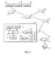
- FIG. 3is a pictorial illustration of the array of FIG. 2 following formation of an interactive network
- FIG. 4is an exploded view of one configuration of a sensor module in accordance with the embodiment of FIG. 1 ;
- FIG. 5is a flow chart illustrating an operational embodiment of the present invention.
- FIG. 6is a flow chart illustrating another operational embodiment of the present invention.
- FIG. 1there is shown a plurality of individual sensor modules 9 deployed at spaced locations, for example, along a peripheral boundary of an area to be secured.
- additional sensor modules 11may be deployed along pathways or entryways or other locations within the area to be secured in order to monitor traffic or other activities.
- Each sensor module 9 , 11includes a proximity sensor 13 that may be, for example, a passive infrared sensor that responds to the presence or proximity of a warm object such as an individual, vehicle, or the like.
- the proximity sensor 13may be an active infrared or radio or ultrasonic sensor that emits a signal and senses any echo attributable to presence of a reflective object within a sensing field of view.
- other sensorssuch as vibration detectors or light detectors may be used to respond to the presence of an intruding object.
- each sensor module 9includes a transceiver 15 that responds to radio transmissions from other similar modules, and also transmits radio signals to other modules for reception and relay or re-transmission thereby of such received signals.
- an array of modules 9 , 11forms an interactive, distributed network that operates self-adaptively on operative modules 9 .
- adjacent operative modules 9 , 11are capable of interacting to reconfigure a different distributed array, as later described herein.
- Each sensor module 9 , 11also includes a processor 17 that controls operation of the transceiver 15 and proximity sensor 13 to produce data signals for transmission via the transceiver 15 to one or more adjacent modules 9 , 11 .
- the processor 17may control random recurrences of monitoring events to amass information about any changes in circumstances associated with proximate objects, for conversion to data signals to be transmitted via transceiver 15 .
- Each processor 17may include alarm utilization circuitry for initiating alarms, commencing video surveillance via local video camera 10 , or the like, upon command or upon sensing a change in proximity circumstances.
- the distributed network of modules 9 , 11may also communicate with a central computer 19 via a transceiver 21 acting as a gateway between the computer 19 and the distributed array of modules 9 , 11 for communicating signals between the computer 19 and the network of interactive modules 9 , 11 , 12 .
- Computer 19may operate on a database 23 of address or identification code for each module 9 , 11 , 12 in order to communicate through the network of modules 9 , 11 that each have different addresses or identification codes, to a particular module having a selected address.
- each module 9 , 11 , 12may transmit and receive data signals specifically designating the module by its unique identification code or address.
- each module 9 , 11 , 12is powered by self-contained batteries 25 and/or photovoltaic cells 27 that also operate to charge the batteries 25 .
- the modules 9 , 11may be disposed within conventional traffic-marking cones, as illustrated in FIG. 4 , for convenient mobile placement or may be mounted on fence posts, or may be mounted on spikes driven into the ground within and about an area to be secured, or may be otherwise suitably mounted in, on and about areas or passageways that are to be secured against unauthorized intrusions.
- the plurality of modules 9 , 11may interact, as later described herein, to distinguish between a false intrusion detection event and a true event for which alarm and other responses should be initiated.
- Certain proximity sensorssuch as passive infrared sensors or ultrasonic sensors may respond to a breeze of different temperature, or to objects blowing by in a strong wind and thereby create a false intrusion detection.
- such false intrusion detectionsare recognized to be predominantly random events attributable to stimulation of one sensor and likely not an adjacent sensor.
- correlation of sensor events among multiple adjacent sensorspermits discrimination against false intrusion detections.
- Additional informationis extracted throughout the network of multiple sensors, for example, responsive to an entry location and to movement along a path of travel.
- the additional informationincluding, for example, time and duration and location of one or more sensor stimulations may be transmitted back to the central computer 19 through the network of modules 9 , 11 for computerized correlation analysis of the additional information to verify a true intrusion event.
- modules 9 , 11 disposed within or about a small areamay communicate the additional information between modules to correlate the sensor stimulations and locally perform computerized correlation analysis within one or more of the processors 17 to verify a true intrusion event.
- the sensor information derived from a plurality of adjacent or neighboring modules 9 , 11may be analyzed by the central computer 19 , or by local processors 17 , to triangulate the location and path of movement of an intruder for producing location coordinates to which an installed video surveillance camera may be aligned.
- one or more stand-alone, battery-operated video surveillance cameras 12 with different addresses in the networkmay be selectively activated in an adjacent region only upon true intrusion events in the region for maximum unattended battery operation of the cameras 12 .
- Such cameras 12 of diminutive size and low power consumptionmay operate for brief intervals during a true intrusion event to relay image data through the network of modules 9 , 11 for storage in the database 23 along with such additional information as time of intrusion, duration and coordinates along a path of movement through the secured area, and the like.
- Such cameras 10 of diminutive sizemay be housed in a module 9 , 11 or conventional surveillance cameras 12 may be mounted in protected areas in association with high-level illumination 14 to be activated in response to an addressed command from computer 19 following analysis thereby of a true intrusion.
- battery-powered lighting 14may also be incorporated into each module 9 , 11 to be energized only upon determination by one or more processors 17 , or by central computer 19 , 21 , 23 of a true intrusion occurring in the vicinity of such module 9 , 11 .
- the video surveillance cameras 10 , 12may be operated selectively under control of the central computer 19 , 21 , 23 during no intrusion activity to scan the adjacent vicinity in order to update the database 23 , 45 with image data about the local vicinity.
- a module( 9 - 1 to 9 - 5 ) must select a parent or superior node to which to forward messages.
- the radio transmissions or beacons from neighboring modulesinform a module about how well the NM's can receive its messages which include cost for the NM's to forward a message toward a base station, together with a ‘hop’ count (i.e., number of repeater or message relay operations) to such base station.
- a ‘hop’ counti.e., number of repeater or message relay operations
- Thismay not be enough information by which a module as a subordinate node can select a parent or superior node since a radio link may be highly asymmetrical on such two-way communications.
- a NMmay receive clearly from a module but the module may not receive clearly from the NM. Selecting such NM as a parent would result in a poor communication link resulting in many message repeats and acknowledgements at concomitant cost.
- such a module ( 9 - 1 to 9 - 5 )can also ‘overhear’ a NM's transmissions that include the NM's neighborhood list (NL) as a pre-set maximum number, say 16 , of modules from which the NM can receive. For greater numbers of modules, the NM excludes from the NL those modules with poor or lower-quality reception. Thus, if a receiving module does not detect its broadcast address or ID in a potential parent's NL, then that NM will not be selected as a parent.
- a base station(e.g., 9 - 5 connected to central computer 19 , 21 , 23 ) may be set to accommodate a larger number of modules in its NL to handle more children or subordinate modules for greater prospects of assembling an efficient adaptive network through some selection of modules and relay operations therebetween.
- Transmitted messages from a module ( 9 - 1 to 9 - 5 )contain several factors, including:
- costas a number to be minimized which indicates to NM's the amount of energy required to transmit to a base station.
- the costis a summation of all costs of all ‘hops’ to the base station (a base station 9 - 5 has zero cost to forward messages, so its messages are distinctive from messages of possible parent modules);
- a packet sequence number(e.g., 16-bit integer) that is incremented every time a message is transmitted from the base station 9 - 5 or other module 9 - 1 to 9 - 4 ;
- NLa neighborhood list of all other modules in the vicinity from which the base station or other module can receive, including:
- a moduleselects lowest OC to send a message.
- initialization of the networkis facilitated by the base station ( 9 - 5 ) broadcasting a message including zero costs.
- messages broadcast by all other modules ( 9 - 1 to 9 - 4 )initially include infinite cost (since not yet determined how to route messages to the base, station). And, there are no entries in the NL in initial broadcast messages.
- Data messages from a moduleare sent with a broadcast address since no parent has been selected.
- Modulese.g., 9 - 3 and 9 - 4 ) that can receive base station messages from module 9 - 5 containing zero cost information will recognize that they can forward messages to such base station.
- modules 9 - 3 and 9 - 4 within the reception vicinity of the base station 9 - 5enable the base station to assemble and include within their messages a NL of modules (including modules 9 - 3 and 9 - 4 ) that receive the base station messages. And, these modules then include the base station and other NM in their NL within broadcast messages.
- a parente.g., module 9 - 4
- a parentis then selected as a superior node by other modules as subordinate nodes whose messages each change from a broadcast address to the parent's address.
- the network formationthus propagates across the array to more remote nodes (e.g., modules 9 - 1 and 9 - 2 ) that are not in the reception vicinity of the base station 9 - 5 .
- each modulemay calculate a node cost as the parent's cost plus the cost of the link to the parent (e.g., 9 - 2 ).
- each communication link toward the base statione.g., module 9 - 5
- lowest coste.g., via module 9 - 4 rather than via module 9 - 3
- a transmission path to the base station for a remote modulewill be selected on such lower cost (e.g., from module 9 - 2 via module 9 - 3 , or from module 9 - 1 via module 9 - 4 or 9 - 3 ), and such replaced module will be identified by the absence of its address in successive transmission by other, adjacent modules or in failure of response to a polling command from computer 19 , 21 , 23 (e.g., module 9 - 5 ).
- the module 9may be configured in one embodiment as a truncated cone with a descending attached housing 16 that is suitably configured for containing batteries 25 .
- the top or truncationmay support photovoltaic or solar cells 27 that are connected to charge batteries 25 .
- the module 9conforms generally to the conical shape of a conventional highway marker 18 and is dimensioned to fit into the top or truncation of the highway market 18 as one form of support. Such cones may be conveniently stacked for storage.
- the module 9may be suitably packaged differently, for example, as a top knob for positioning on a fence post, or the like.
- the module 9includes one or more proximity sensors 13 such as infrared detectors equipped with wide-angle lenses and disposed at different angular orientations about the periphery of the module 9 to establish overlapping fields of view.
- One or more miniature video cameras 10may also be housed in the module 9 to include azimuth, elevation and focus operations under control of processor 17 in conventional manner.
- a proximity-sensing moduledetects 35 the transient presence of an object.
- detectionmay be by one or more of passive infrared or acoustic or magnetic sensing, or by active transmission and reception of transmitted and reflected energy.
- proximity sensingmay be sampled or swept along all directional axes oriented about the placement of each module.
- the processor 17 in each module 9 , 11controls operation of the proximity sensor 13 of that module in order to generate data signals for transmission 39 to adjacent modules.
- the processor 17may establish sensing intervals independently, or in response 37 to transmission thereto (via designated address or identification code) of commands from the central computer 19 .
- a module 9receives and relays or re-transmits 41 data signals received from adjacent modules in the array of modules 9 , 11 , 12 .
- data signals generated and transmitted or received and re-transmitted by a module among modulesare received 43 by the central computer 19 which may analyze 47 the data signals to triangulate the location and path of movement of an intruder, or may analyze 47 the data signals relative to a database 45 of information, for example, regarding conditions about each selected module 9 , 11 , 12 or to compare intruder images against database images of the vicinity in order to trigger alarm conditions 49 , or adjust 51 the database, or transmit 53 data or command signals to all or selected, addressed modules 9 , 11 , 12 .
- One typical alarm response 49may include commands for operation of an installed video surveillance camera 12 and associated high-level illumination 14 via its designated address as located in the vicinity of a detected true intrusion.
- Computer analysis of data signals from adjacent addressed modules 9 , 11may profile the characteristics of changed circumstances in the vicinity of the addressed modules, and may identify an intruding object from database information on profiles and characteristics of various objects such as individuals, vehicles, and the like.
- the processor 17 of each modulemay include an output utilization circuit for controlling initialization of alarm conditions, or video surveillance of the vicinity, or the like.
- alarm utilization 49 determined from analyses of received data signals by the central computer 19may facilitate triangulating to coordinates of the intrusion locations and along paths of movement for controlling camera 12 surveillance, and may also actuate overall alarm responses concerning the entire secured area.
- the network assembled in a manner as previously described hereinoperates in time synchronized mode to conserve battery power.
- the control statione.g., computer 19
- the control stationperiodically broadcasts a reference time to all modules 9 , 11 , 12 in the network, either directly to proximate modules or via reception and re-broadcasts through proximate modules to more remote modules.
- Modulesmay correct for propagation delays through the assembly network, for example, via correlation with accumulated cost numbers as previously described herein.
- each transceivertransmits and/or receives broadcast data messages (in the absence of an intrusion anywhere), for example, of the type previously described to assess continuity of the assembled network, or to re-establish communications in the absence or failure of a module 9 , 11 , 12 previously assembled within the network.
- such time synchronismfacilitates accurately recording time of detection across the entire network and promotes accurate comparisons of detection times among different modules. This enhances accuracy of triangulation among the modules 9 , 11 to pinpoint the location, path of movement, time of occurrences, estimated trajectory of movement, and the like, of an actual intruder.
- true intrusionas determined by such time-oriented correlations of intruder movements among the modules 9 , 11 , 12 more accurately activates and aligns the cameras 10 , 12 for pinpoint image formation of the intruder over the course of its movements.
- modules 9 , 11 within the sensor field of view of an intrudermay communicate data signals to verify that all or some of the proximate modules 9 , 11 also detect the intrusion.
- An intrusion sensed by one module 9 , 11 and not also sensed by at least one additional modulemay be disregarded as constituting a false intrusion or other anomaly using a triangulation algorithm or routine, the CPU's 17 of the modules 9 , 11 within range of the intruding object determine the relative locations and control their associated cameras 10 , 12 to scan, scroll and zoom onto the intruder location from the various module locations. If intrusion activity is sensed during nighttime (e.g., indicated via solarcell inactivity), then associated lighting 10 , 14 may also be activated under control of the associated CPU 17 . If other adjacent modules do not sense or otherwise correlate the intruder information, the intrusion is disregarded as false, and the modules may return to low-power operating mode.
- Camera images formed of a time intrusionare broadcast and relayed or re-broadcast over the network to the central computer 19 for comparisons there with image data in database 23 of the background and surroundings of the addressed modules 9 , 11 that broadcast the intruder image data.
- the central computer 19may then broadcast further commands for camera tracking of the intruder, and initiate security alerts for human or other interventions.
- the central computer 19In time synchronized manner, in the absence of any sensed intrusion, the central computer 19 periodically broadcasts a command to actuate cameras 10 of the modules 9 , 11 , 12 to scan the surroundings at various times of day and night and seasons to update related sections of the database 23 for later more accurate comparisons with suspected intruder images.
- a set of units A and B of the modules 9 , 11 , 12are initially operating 61 in low-power mode (i.e., and transceiver 15 and camera 10 and lights 14 unenergized, and CPU 17 in low-level operation), these units A and B may sense an intruding object 63 at about the same time, or at delayed times that overlap or correlate as each sensor ‘awakens’ 65 its associated CPU or micro-processor and transceiver to full activity.
- low-power modei.e., and transceiver 15 and camera 10 and lights 14 unenergized, and CPU 17 in low-level operation
- these units A and Bmay sense an intruding object 63 at about the same time, or at delayed times that overlap or correlate as each sensor ‘awakens’ 65 its associated CPU or micro-processor and transceiver to full activity.
- Local cameras and lightsmay be activated 69 and controlled to form intruder image data for transmission back through the assembled network to the central computer 19 .
- the image datais compared 71 with background image data from database 23 as stored therein by time of day, season, or the like, for determination of true intrusion.
- commandsare broadcast throughout the network to activate cameras (and lights, as may be required) in order to coordinate intrusion movements, path, times of activities, image data and other useful information to log and store regarding the event.
- alarm informationmay be forwarded 73 to a control station to initiate human or other intervention.
- the lights 14may operate in the infrared spectral region to complement infrared-sensing cameras 10 and to avoid alerting a human intruder about the active surveillance.
- the deployable sensor modules and the self-adaptive networks formed therebygreatly facilitate establishing surveillance within and around a secure area without time-consuming and expensive requirements of hard-wiring of modules to a central computer.
- data signals generated by, or received from other adjacent modules and re-transmitted among adjacent modulespromotes self-adaptive formation of distributed sensing networks that can self configure around blocked or inoperative modules to preserve integrity of the surveillance established by the interactive sensing modules.
Landscapes
- Physics & Mathematics (AREA)
- General Physics & Mathematics (AREA)
- Business, Economics & Management (AREA)
- Emergency Management (AREA)
- Engineering & Computer Science (AREA)
- Computer Security & Cryptography (AREA)
- Computer Networks & Wireless Communication (AREA)
- Alarm Systems (AREA)
Abstract
Description
- i) the ID of each NM; and
- ii) a reception estimate of how well a module receives messages from such NM as determined from processing the sequence numbers in such message packets to compute a percent of lost packets.
PF=(% of module's packets received by NM)×(% of possible parent's packets received by module).
OC=cost of NM/PF.
Claims (15)
Priority Applications (6)
| Application Number | Priority Date | Filing Date | Title |
|---|---|---|---|
| US11/152,350US8144197B2 (en) | 2005-03-30 | 2005-06-13 | Adaptive surveillance network and method |
| US11/345,737US7760109B2 (en) | 2005-03-30 | 2006-02-01 | Interactive surveillance network and method |
| US11/433,194US8115593B2 (en) | 2005-03-30 | 2006-05-11 | Adaptive network and method |
| US11/833,799US8189536B2 (en) | 2005-03-30 | 2007-08-03 | Delivery of data packets via aggregated spatial distribution overlay on a mesh network |
| US13/356,987US8707075B2 (en) | 2005-03-30 | 2012-01-24 | Adaptive network and method |
| US13/533,428US20120290857A1 (en) | 2005-03-30 | 2012-06-26 | Adaptive network and method |
Applications Claiming Priority (2)
| Application Number | Priority Date | Filing Date | Title |
|---|---|---|---|
| US11/095,640US7705729B2 (en) | 2005-03-30 | 2005-03-30 | Surveillance system and method |
| US11/152,350US8144197B2 (en) | 2005-03-30 | 2005-06-13 | Adaptive surveillance network and method |
Related Parent Applications (1)
| Application Number | Title | Priority Date | Filing Date |
|---|---|---|---|
| US11/095,640Continuation-In-PartUS7705729B2 (en) | 2005-03-30 | 2005-03-30 | Surveillance system and method |
Related Child Applications (1)
| Application Number | Title | Priority Date | Filing Date |
|---|---|---|---|
| US11/345,737Continuation-In-PartUS7760109B2 (en) | 2005-03-30 | 2006-02-01 | Interactive surveillance network and method |
Publications (2)
| Publication Number | Publication Date |
|---|---|
| US20100013933A1 US20100013933A1 (en) | 2010-01-21 |
| US8144197B2true US8144197B2 (en) | 2012-03-27 |
Family
ID=37069701
Family Applications (1)
| Application Number | Title | Priority Date | Filing Date |
|---|---|---|---|
| US11/152,350Expired - Fee RelatedUS8144197B2 (en) | 2005-03-30 | 2005-06-13 | Adaptive surveillance network and method |
Country Status (1)
| Country | Link |
|---|---|
| US (1) | US8144197B2 (en) |
Cited By (4)
| Publication number | Priority date | Publication date | Assignee | Title |
|---|---|---|---|---|
| US20100277297A1 (en)* | 2007-09-24 | 2010-11-04 | Matthias Eckel | Driver assistance system and method for operating same |
| US20130278422A1 (en)* | 2012-04-24 | 2013-10-24 | At&T Intellectual Property I, Lp | Method and apparatus for processing sensor data of detected objects |
| US20150206415A1 (en)* | 2014-01-17 | 2015-07-23 | Gojo Industries, Inc. | Sensor configuration |
| US20170299696A1 (en)* | 2014-10-09 | 2017-10-19 | Utc Fire & Security Corporation | Advanced identification techniques for security and safety systems |
Families Citing this family (18)
| Publication number | Priority date | Publication date | Assignee | Title |
|---|---|---|---|---|
| US8471910B2 (en)* | 2005-08-11 | 2013-06-25 | Sightlogix, Inc. | Methods and apparatus for providing fault tolerance in a surveillance system |
| US8284254B2 (en)* | 2005-08-11 | 2012-10-09 | Sightlogix, Inc. | Methods and apparatus for a wide area coordinated surveillance system |
| US20070076662A1 (en)* | 2005-09-30 | 2007-04-05 | Nikhil Jain | Handoffs in a wireless local area network |
| US20070177023A1 (en)* | 2006-01-31 | 2007-08-02 | Beuhler Allyson J | System and method to provide an adaptive camera network |
| DE102006033147A1 (en)* | 2006-07-18 | 2008-01-24 | Robert Bosch Gmbh | Surveillance camera, procedure for calibration of the security camera and use of the security camera |
| US8040226B2 (en)* | 2007-04-02 | 2011-10-18 | Datachassi Dc Ab | Vehicle surveillance and communication system |
| US20090268023A1 (en)* | 2008-04-27 | 2009-10-29 | Wen-Hsiung Hsieh | Surveillance camera device with a light source |
| US20110069179A1 (en)* | 2009-09-24 | 2011-03-24 | Microsoft Corporation | Network coordinated event capture and image storage |
| JP2011172205A (en)* | 2010-01-20 | 2011-09-01 | Canon Inc | Video information processing apparatus and method |
| US8769688B2 (en)* | 2011-09-23 | 2014-07-01 | Universidad Politécnica de P.R. | Simultaneous determination of a computer location and user identification |
| US9251692B2 (en)* | 2013-03-15 | 2016-02-02 | Honeywell International Inc. | GPS directed intrusion system with data acquisition |
| US9871959B1 (en)* | 2014-01-11 | 2018-01-16 | Joseph F Hlatky | Adaptive trail cameras |
| US20150312535A1 (en)* | 2014-04-23 | 2015-10-29 | International Business Machines Corporation | Self-rousing surveillance system, method and computer program product |
| GB201420219D0 (en)* | 2014-11-13 | 2014-12-31 | D J Byers Ltd | Detection system |
| DE102016213807A1 (en)* | 2016-07-27 | 2018-02-01 | Robert Bosch Gmbh | Concept for monitoring a parking lot for motor vehicles |
| DE102016213982A1 (en)* | 2016-07-29 | 2018-02-01 | Robert Bosch Gmbh | Concept for monitoring a parking lot for motor vehicles |
| CN107094223A (en)* | 2017-03-17 | 2017-08-25 | 奥克斯空调股份有限公司 | Obtain the method and device of the high-definition image of intrusion target |
| US11558763B2 (en)* | 2020-03-03 | 2023-01-17 | Qualcomm Incorporated | Electronic shelf label (ESL) efficient reconnect |
Citations (56)
| Publication number | Priority date | Publication date | Assignee | Title |
|---|---|---|---|---|
| US4002886A (en) | 1975-06-20 | 1977-01-11 | Ronald Murl Sundelin | Electronic price display unit |
| US4418333A (en) | 1981-06-08 | 1983-11-29 | Pittway Corporation | Appliance control system |
| US4766295A (en) | 1987-03-02 | 1988-08-23 | H.E. Butt Grocery Company | Electronic pricing display system |
| US5352957A (en) | 1989-12-21 | 1994-10-04 | Zumtobel Aktiengessellschaft | Appliance control system with programmable receivers |
| US5365154A (en) | 1991-07-12 | 1994-11-15 | North Coast Electronics, Inc. | Appliance control system and method |
| US5640151A (en) | 1990-06-15 | 1997-06-17 | Texas Instruments Incorporated | Communication system for communicating with tags |
| US5697061A (en) | 1993-09-22 | 1997-12-09 | Seattle Silicon Corporation | Method and apparatus for providing information concerning products, using radio frequency transmissions |
| US5841365A (en) | 1993-09-22 | 1998-11-24 | Seattle Silicon Corporation | Method and apparatus for communicating with a product label |
| US5995015A (en) | 1989-05-16 | 1999-11-30 | Electronic Advertising Solutions Innovators, Inc. D/B/A Easi, Inc. | Remote electronic information display system for retail facility |
| US6032109A (en) | 1996-10-21 | 2000-02-29 | Telemonitor, Inc. | Smart sensor module |
| US6078269A (en) | 1997-11-10 | 2000-06-20 | Safenight Technology Inc. | Battery-powered, RF-interconnected detector sensor system |
| US6208247B1 (en) | 1998-08-18 | 2001-03-27 | Rockwell Science Center, Llc | Wireless integrated sensor network using multiple relayed communications |
| US6243654B1 (en) | 1997-10-07 | 2001-06-05 | Telemonitor, Inc. | Transducer assembly with smart connector |
| US20020044533A1 (en)* | 2000-08-07 | 2002-04-18 | Paramvir Bahl | Distributed topology control for wireless multi-hop sensor networks |
| US6381467B1 (en) | 2000-06-22 | 2002-04-30 | Motorola, Inc. | Method and apparatus for managing an ad hoc wireless network |
| US6392562B1 (en) | 1998-12-28 | 2002-05-21 | Caterpillar Inc. | Fluid particle sensor apparatus and method for transmitting data to a remote receiver |
| US20030025599A1 (en) | 2001-05-11 | 2003-02-06 | Monroe David A. | Method and apparatus for collecting, sending, archiving and retrieving motion video and still images and notification of detected events |
| US20030043028A1 (en) | 2001-08-30 | 2003-03-06 | Yuji Torikai | Home network system |
| US20030063585A1 (en) | 2001-08-03 | 2003-04-03 | Honeywell International Inc. | Energy aware network management |
| US6587739B1 (en) | 2000-09-29 | 2003-07-01 | Sunbeam Products, Inc. | Appliance communication and control system and appliances for use in same |
| US20040010492A1 (en) | 2002-05-28 | 2004-01-15 | Xerox Corporation | Systems and methods for constrained anisotropic diffusion routing within an ad hoc network |
| US6690289B1 (en) | 1997-06-12 | 2004-02-10 | Microsoft Corporation | Message formatting, authentication, and error detection in home control systems |
| US20040098218A1 (en) | 2000-01-13 | 2004-05-20 | Toku Ito | System for acquiring data from a facility and method |
| US6745027B2 (en) | 2000-12-22 | 2004-06-01 | Seekernet Incorporated | Class switched networks for tracking articles |
| US6749116B2 (en) | 2000-09-19 | 2004-06-15 | Michael J. Massaro | Display system for store shelves |
| US6750769B1 (en) | 2002-12-12 | 2004-06-15 | Sun Microsystems, Inc. | Method and apparatus for using RFID tags to determine the position of an object |
| US20040122833A1 (en) | 2001-02-23 | 2004-06-24 | Forth J. Bradford | Intelligent electronic device having network access |
| US6822568B2 (en) | 2002-01-23 | 2004-11-23 | Lucent Technologies Inc. | Space area network |
| US20040233284A1 (en)* | 2001-10-09 | 2004-11-25 | Vehicle Enhancement Systems, Inc. | Apparatus and methods for providing surveillance data concerning a scene of interest to a user located at a remote location |
| US6844821B2 (en) | 2001-02-15 | 2005-01-18 | Illinois Tool Works Inc. | Electronic display system tag, related interface protocal and display methods |
| US6859831B1 (en)* | 1999-10-06 | 2005-02-22 | Sensoria Corporation | Method and apparatus for internetworked wireless integrated network sensor (WINS) nodes |
| US20050099500A1 (en)* | 2003-11-11 | 2005-05-12 | Canon Kabushiki Kaisha | Image processing apparatus, network camera system, image processing method and program |
| US20050131736A1 (en)* | 2003-12-16 | 2005-06-16 | Adventium Labs And Red Wing Technologies, Inc. | Activity monitoring |
| US6930596B2 (en)* | 2002-07-19 | 2005-08-16 | Ut-Battelle | System for detection of hazardous events |
| US20050218218A1 (en) | 2004-03-31 | 2005-10-06 | Karl Koster | Systems and methods for an electronic programmable merchandise tag |
| US20050237153A1 (en) | 2004-04-21 | 2005-10-27 | Jack Chen | Device for electronically pricing product on a shelf |
| US6961709B2 (en) | 2001-04-02 | 2005-11-01 | Ncr Corporation | System and method of managing inventory |
| US7035240B1 (en) | 2000-12-27 | 2006-04-25 | Massachusetts Institute Of Technology | Method for low-energy adaptive clustering hierarchy |
| US20060130142A1 (en) | 2004-11-30 | 2006-06-15 | Mester Michael L | Propagation protection within a network |
| US20060176239A1 (en) | 2005-02-04 | 2006-08-10 | Philip Morris Usa Inc. | Display management system |
| US7090125B2 (en) | 2003-12-18 | 2006-08-15 | Altierre Corporation | Low power wireless display tag systems and methods |
| US20060187040A1 (en) | 2005-02-04 | 2006-08-24 | Philip Morris Usa Inc. | Controllable RFID card |
| US7103511B2 (en) | 1998-10-14 | 2006-09-05 | Statsignal Ipc, Llc | Wireless communication networks for providing remote monitoring of devices |
| US20060229086A1 (en) | 2005-03-30 | 2006-10-12 | Broad Alan S | Surveillance system and method |
| US20060271667A1 (en) | 1998-12-15 | 2006-11-30 | Pittway Corporation | Multi-processor communications system incorporating prioritized messaging |
| US7152040B1 (en) | 2003-05-27 | 2006-12-19 | Microsoft Corporation | Electronic shelf label |
| US7176808B1 (en) | 2000-09-29 | 2007-02-13 | Crossbow Technology, Inc. | System and method for updating a network of remote sensors |
| US7231180B2 (en) | 2004-03-24 | 2007-06-12 | Honeywell International, Inc. | Aircraft engine sensor network using wireless sensor communication modules |
| US7360095B2 (en) | 2003-05-22 | 2008-04-15 | International Business Machines Corporation | Method and apparatus for a proximity warning system |
| US7369047B2 (en) | 2005-03-30 | 2008-05-06 | Crossbow Technology, Inc. | Adaptive sensing network |
| US7397368B2 (en) | 2004-09-22 | 2008-07-08 | Kevin L Otto | Remote field command post |
| US7424527B2 (en) | 2001-10-30 | 2008-09-09 | Sipco, Llc | System and method for transmitting pollution information over an integrated wireless network |
| US7429936B2 (en) | 2004-08-26 | 2008-09-30 | Massachusetts Institute Of Technology | Parasitic mobility in dynamically distributed sensor networks |
| US7440735B2 (en) | 2002-10-23 | 2008-10-21 | Rosemount Inc. | Virtual wireless transmitter |
| US7656829B2 (en) | 2004-01-06 | 2010-02-02 | Samsung Electronics Co., Ltd. | System and method for determining data transmission path in communication system consisting of nodes |
| US7676195B2 (en) | 2004-09-10 | 2010-03-09 | Nivis, Llc | System and method for communicating messages in a mesh network |
- 2005
- 2005-06-13USUS11/152,350patent/US8144197B2/ennot_activeExpired - Fee Related
Patent Citations (56)
| Publication number | Priority date | Publication date | Assignee | Title |
|---|---|---|---|---|
| US4002886A (en) | 1975-06-20 | 1977-01-11 | Ronald Murl Sundelin | Electronic price display unit |
| US4418333A (en) | 1981-06-08 | 1983-11-29 | Pittway Corporation | Appliance control system |
| US4766295A (en) | 1987-03-02 | 1988-08-23 | H.E. Butt Grocery Company | Electronic pricing display system |
| US5995015A (en) | 1989-05-16 | 1999-11-30 | Electronic Advertising Solutions Innovators, Inc. D/B/A Easi, Inc. | Remote electronic information display system for retail facility |
| US5352957A (en) | 1989-12-21 | 1994-10-04 | Zumtobel Aktiengessellschaft | Appliance control system with programmable receivers |
| US5640151A (en) | 1990-06-15 | 1997-06-17 | Texas Instruments Incorporated | Communication system for communicating with tags |
| US5365154A (en) | 1991-07-12 | 1994-11-15 | North Coast Electronics, Inc. | Appliance control system and method |
| US5697061A (en) | 1993-09-22 | 1997-12-09 | Seattle Silicon Corporation | Method and apparatus for providing information concerning products, using radio frequency transmissions |
| US5841365A (en) | 1993-09-22 | 1998-11-24 | Seattle Silicon Corporation | Method and apparatus for communicating with a product label |
| US6032109A (en) | 1996-10-21 | 2000-02-29 | Telemonitor, Inc. | Smart sensor module |
| US6690289B1 (en) | 1997-06-12 | 2004-02-10 | Microsoft Corporation | Message formatting, authentication, and error detection in home control systems |
| US6243654B1 (en) | 1997-10-07 | 2001-06-05 | Telemonitor, Inc. | Transducer assembly with smart connector |
| US6078269A (en) | 1997-11-10 | 2000-06-20 | Safenight Technology Inc. | Battery-powered, RF-interconnected detector sensor system |
| US6208247B1 (en) | 1998-08-18 | 2001-03-27 | Rockwell Science Center, Llc | Wireless integrated sensor network using multiple relayed communications |
| US7103511B2 (en) | 1998-10-14 | 2006-09-05 | Statsignal Ipc, Llc | Wireless communication networks for providing remote monitoring of devices |
| US20060271667A1 (en) | 1998-12-15 | 2006-11-30 | Pittway Corporation | Multi-processor communications system incorporating prioritized messaging |
| US6392562B1 (en) | 1998-12-28 | 2002-05-21 | Caterpillar Inc. | Fluid particle sensor apparatus and method for transmitting data to a remote receiver |
| US6859831B1 (en)* | 1999-10-06 | 2005-02-22 | Sensoria Corporation | Method and apparatus for internetworked wireless integrated network sensor (WINS) nodes |
| US20040098218A1 (en) | 2000-01-13 | 2004-05-20 | Toku Ito | System for acquiring data from a facility and method |
| US6381467B1 (en) | 2000-06-22 | 2002-04-30 | Motorola, Inc. | Method and apparatus for managing an ad hoc wireless network |
| US20020044533A1 (en)* | 2000-08-07 | 2002-04-18 | Paramvir Bahl | Distributed topology control for wireless multi-hop sensor networks |
| US6749116B2 (en) | 2000-09-19 | 2004-06-15 | Michael J. Massaro | Display system for store shelves |
| US7176808B1 (en) | 2000-09-29 | 2007-02-13 | Crossbow Technology, Inc. | System and method for updating a network of remote sensors |
| US6587739B1 (en) | 2000-09-29 | 2003-07-01 | Sunbeam Products, Inc. | Appliance communication and control system and appliances for use in same |
| US6745027B2 (en) | 2000-12-22 | 2004-06-01 | Seekernet Incorporated | Class switched networks for tracking articles |
| US7035240B1 (en) | 2000-12-27 | 2006-04-25 | Massachusetts Institute Of Technology | Method for low-energy adaptive clustering hierarchy |
| US6844821B2 (en) | 2001-02-15 | 2005-01-18 | Illinois Tool Works Inc. | Electronic display system tag, related interface protocal and display methods |
| US20040122833A1 (en) | 2001-02-23 | 2004-06-24 | Forth J. Bradford | Intelligent electronic device having network access |
| US6961709B2 (en) | 2001-04-02 | 2005-11-01 | Ncr Corporation | System and method of managing inventory |
| US20030025599A1 (en) | 2001-05-11 | 2003-02-06 | Monroe David A. | Method and apparatus for collecting, sending, archiving and retrieving motion video and still images and notification of detected events |
| US20030063585A1 (en) | 2001-08-03 | 2003-04-03 | Honeywell International Inc. | Energy aware network management |
| US20030043028A1 (en) | 2001-08-30 | 2003-03-06 | Yuji Torikai | Home network system |
| US20040233284A1 (en)* | 2001-10-09 | 2004-11-25 | Vehicle Enhancement Systems, Inc. | Apparatus and methods for providing surveillance data concerning a scene of interest to a user located at a remote location |
| US7424527B2 (en) | 2001-10-30 | 2008-09-09 | Sipco, Llc | System and method for transmitting pollution information over an integrated wireless network |
| US6822568B2 (en) | 2002-01-23 | 2004-11-23 | Lucent Technologies Inc. | Space area network |
| US20040010492A1 (en) | 2002-05-28 | 2004-01-15 | Xerox Corporation | Systems and methods for constrained anisotropic diffusion routing within an ad hoc network |
| US6930596B2 (en)* | 2002-07-19 | 2005-08-16 | Ut-Battelle | System for detection of hazardous events |
| US7440735B2 (en) | 2002-10-23 | 2008-10-21 | Rosemount Inc. | Virtual wireless transmitter |
| US6750769B1 (en) | 2002-12-12 | 2004-06-15 | Sun Microsystems, Inc. | Method and apparatus for using RFID tags to determine the position of an object |
| US7360095B2 (en) | 2003-05-22 | 2008-04-15 | International Business Machines Corporation | Method and apparatus for a proximity warning system |
| US7152040B1 (en) | 2003-05-27 | 2006-12-19 | Microsoft Corporation | Electronic shelf label |
| US20050099500A1 (en)* | 2003-11-11 | 2005-05-12 | Canon Kabushiki Kaisha | Image processing apparatus, network camera system, image processing method and program |
| US20050131736A1 (en)* | 2003-12-16 | 2005-06-16 | Adventium Labs And Red Wing Technologies, Inc. | Activity monitoring |
| US7090125B2 (en) | 2003-12-18 | 2006-08-15 | Altierre Corporation | Low power wireless display tag systems and methods |
| US7656829B2 (en) | 2004-01-06 | 2010-02-02 | Samsung Electronics Co., Ltd. | System and method for determining data transmission path in communication system consisting of nodes |
| US7231180B2 (en) | 2004-03-24 | 2007-06-12 | Honeywell International, Inc. | Aircraft engine sensor network using wireless sensor communication modules |
| US20050218218A1 (en) | 2004-03-31 | 2005-10-06 | Karl Koster | Systems and methods for an electronic programmable merchandise tag |
| US20050237153A1 (en) | 2004-04-21 | 2005-10-27 | Jack Chen | Device for electronically pricing product on a shelf |
| US7429936B2 (en) | 2004-08-26 | 2008-09-30 | Massachusetts Institute Of Technology | Parasitic mobility in dynamically distributed sensor networks |
| US7676195B2 (en) | 2004-09-10 | 2010-03-09 | Nivis, Llc | System and method for communicating messages in a mesh network |
| US7397368B2 (en) | 2004-09-22 | 2008-07-08 | Kevin L Otto | Remote field command post |
| US20060130142A1 (en) | 2004-11-30 | 2006-06-15 | Mester Michael L | Propagation protection within a network |
| US20060187040A1 (en) | 2005-02-04 | 2006-08-24 | Philip Morris Usa Inc. | Controllable RFID card |
| US20060176239A1 (en) | 2005-02-04 | 2006-08-10 | Philip Morris Usa Inc. | Display management system |
| US7369047B2 (en) | 2005-03-30 | 2008-05-06 | Crossbow Technology, Inc. | Adaptive sensing network |
| US20060229086A1 (en) | 2005-03-30 | 2006-10-12 | Broad Alan S | Surveillance system and method |
Non-Patent Citations (5)
| Title |
|---|
| Crossbow Technology, "Xmesh Network Layer," 2006, 1 page. |
| IEEE Instrumentation and Measurement Society, "IEEE Standard for a Smart Transducer Interface for Sensors and Actuators-Transducers to Microprocessor Communication Protocols and Transducers Electronic Data Sheet (TEDS) Formats", IEEE Std. 1451.2-1997, 1998, The Institute of Electrical and Electronics Engineers, Inc. , 125 Pages. |
| IEEE Instrumentation and Measurement Society, "IEEE Standard for a Smart Transducer Interface for Sensors and Actuators—Transducers to Microprocessor Communication Protocols and Transducers Electronic Data Sheet (TEDS) Formats", IEEE Std. 1451.2-1997, 1998, The Institute of Electrical and Electronics Engineers, Inc. , 125 Pages. |
| IEEE Standards for A Smart Transducer Interface for Sensors and Actuators-Mixed-Mode Communication Protocols and Transducer Electronic Data Sheet (TEDS) Formats, IEEE Standards 1451.4-2004, IEEE Instrumentation and Measurement Society, 2004, 439 Pages. |
| IEEE Standards for A Smart Transducer Interface for Sensors and Actuators—Mixed-Mode Communication Protocols and Transducer Electronic Data Sheet (TEDS) Formats, IEEE Standards 1451.4-2004, IEEE Instrumentation and Measurement Society, 2004, 439 Pages. |
Cited By (15)
| Publication number | Priority date | Publication date | Assignee | Title |
|---|---|---|---|---|
| US9000902B2 (en)* | 2007-09-24 | 2015-04-07 | Robert Bosch Gmbh | Driver assistance system and method for operating same |
| US20100277297A1 (en)* | 2007-09-24 | 2010-11-04 | Matthias Eckel | Driver assistance system and method for operating same |
| US9875627B2 (en)* | 2012-04-24 | 2018-01-23 | At&T Intellectual Property I, L.P. | Method and apparatus for processing sensor data of detected objects |
| US9293016B2 (en)* | 2012-04-24 | 2016-03-22 | At&T Intellectual Property I, Lp | Method and apparatus for processing sensor data of detected objects |
| US20160162674A1 (en)* | 2012-04-24 | 2016-06-09 | At&T Intellectual Property I, Lp | Method and apparatus for processing sensor data of detected objects |
| US9626496B2 (en)* | 2012-04-24 | 2017-04-18 | At&T Intellectual Property I, L.P. | Method and apparatus for processing sensor data of detected objects |
| US20170186292A1 (en)* | 2012-04-24 | 2017-06-29 | At&T Intellectual Property I, L.P. | Method and apparatus for processing sensor data of detected objects |
| US20130278422A1 (en)* | 2012-04-24 | 2013-10-24 | At&T Intellectual Property I, Lp | Method and apparatus for processing sensor data of detected objects |
| US20150206415A1 (en)* | 2014-01-17 | 2015-07-23 | Gojo Industries, Inc. | Sensor configuration |
| US9892617B2 (en)* | 2014-01-17 | 2018-02-13 | Gojo Industries, Inc. | Sensor configuration |
| US20180240323A1 (en)* | 2014-01-17 | 2018-08-23 | Gojo Industries, Inc. | Sensor configuration |
| US10504355B2 (en)* | 2014-01-17 | 2019-12-10 | Gojo Industries, Inc. | Sensor configuration |
| US11069217B2 (en)* | 2014-01-17 | 2021-07-20 | Gojo Industries, Inc. | Sensor configuration |
| US20170299696A1 (en)* | 2014-10-09 | 2017-10-19 | Utc Fire & Security Corporation | Advanced identification techniques for security and safety systems |
| US10564258B2 (en)* | 2014-10-09 | 2020-02-18 | Utc Fire & Security Corporation | Advanced identification techniques for security and safety systems |
Also Published As
| Publication number | Publication date |
|---|---|
| US20100013933A1 (en) | 2010-01-21 |
Similar Documents
| Publication | Publication Date | Title |
|---|---|---|
| US7760109B2 (en) | Interactive surveillance network and method | |
| US8144197B2 (en) | Adaptive surveillance network and method | |
| US8115593B2 (en) | Adaptive network and method | |
| US7978061B2 (en) | Surveillance system and method | |
| US8710983B2 (en) | Intelligent sensor network | |
| EP2478712B1 (en) | A monitoring method, a monitoring system and a sensor station | |
| EP1547036B1 (en) | Automatic detection and monitoring of perimeter physical movement | |
| EP2814012B1 (en) | Cooperative intrusion detection | |
| CN101436336B (en) | An intrusion detection system and method | |
| JP4385959B2 (en) | Information collection system | |
| US8005108B1 (en) | Fast deployment of modules in adaptive network | |
| US7940177B2 (en) | System and methods for monitoring security zones | |
| US10242561B1 (en) | Corner security detection device | |
| CN101872536A (en) | An Intrusion Monitoring System Based on Wireless Sensor Network | |
| US20070236343A1 (en) | Surveillance network for unattended ground sensors | |
| CN108428315A (en) | Electronic sentry system | |
| KR101099421B1 (en) | Unmanned watch operation system and method based ubiquitous sensor network | |
| CN208158905U (en) | Electronic sentry system sensor group | |
| KR20140031033A (en) | Node deployment method for surveillance and reconnaissance sensor network system and apparatus thereof | |
| KR102450327B1 (en) | Disater response system based on massive iot network | |
| KR20240003075A (en) | Invasion sensing system using distance measurement | |
| Liu et al. | Applications, models, problems, and solution strategies | |
| JP2007018390A (en) | Intruding object detection method, apparatus, and program | |
| JP7538588B2 (en) | Fire alarm system | |
| KR20250003123A (en) | Invasion sensing system using distance and size measurement |
Legal Events
| Date | Code | Title | Description |
|---|---|---|---|
| AS | Assignment | Owner name:CROSSBOW TECHNOLOGY, INC.,CALIFORNIA Free format text:ASSIGNMENT OF ASSIGNORS INTEREST;ASSIGNOR:BROAD, ALAN S.;REEL/FRAME:016695/0261 Effective date:20050609 Owner name:CROSSBOW TECHNOLOGY, INC., CALIFORNIA Free format text:ASSIGNMENT OF ASSIGNORS INTEREST;ASSIGNOR:BROAD, ALAN S.;REEL/FRAME:016695/0261 Effective date:20050609 | |
| AS | Assignment | Owner name:MEMSIC, INC., MASSACHUSETTS Free format text:ASSIGNMENT OF ASSIGNORS INTEREST;ASSIGNOR:CROSSBOW TECHNOLOGY, INC.;REEL/FRAME:023821/0491 Effective date:20100115 Owner name:MEMSIC, INC.,MASSACHUSETTS Free format text:ASSIGNMENT OF ASSIGNORS INTEREST;ASSIGNOR:CROSSBOW TECHNOLOGY, INC.;REEL/FRAME:023821/0491 Effective date:20100115 | |
| AS | Assignment | Owner name:MEMSIC TRANSDUCER SYSTEMS CO., LTD., CHINA Free format text:ASSIGNMENT OF ASSIGNORS INTEREST;ASSIGNOR:MEMSIC, INC.;REEL/FRAME:025017/0434 Effective date:20100920 | |
| ZAAA | Notice of allowance and fees due | Free format text:ORIGINAL CODE: NOA | |
| ZAAB | Notice of allowance mailed | Free format text:ORIGINAL CODE: MN/=. | |
| STCF | Information on status: patent grant | Free format text:PATENTED CASE | |
| FEPP | Fee payment procedure | Free format text:PAT HOLDER NO LONGER CLAIMS SMALL ENTITY STATUS, ENTITY STATUS SET TO UNDISCOUNTED (ORIGINAL EVENT CODE: STOL); ENTITY STATUS OF PATENT OWNER: LARGE ENTITY | |
| FPAY | Fee payment | Year of fee payment:4 | |
| AS | Assignment | Owner name:ACEINNA TRANSDUCER SYSTEMS CO., LTD., CHINA Free format text:CHANGE OF NAME;ASSIGNOR:MEMSIC TRANSDUCER SYSTEMS CO., LTD.;REEL/FRAME:044273/0720 Effective date:20170807 | |
| MAFP | Maintenance fee payment | Free format text:PAYMENT OF MAINTENANCE FEE, 8TH YEAR, LARGE ENTITY (ORIGINAL EVENT CODE: M1552); ENTITY STATUS OF PATENT OWNER: LARGE ENTITY Year of fee payment:8 | |
| FEPP | Fee payment procedure | Free format text:MAINTENANCE FEE REMINDER MAILED (ORIGINAL EVENT CODE: REM.); ENTITY STATUS OF PATENT OWNER: LARGE ENTITY | |
| LAPS | Lapse for failure to pay maintenance fees | Free format text:PATENT EXPIRED FOR FAILURE TO PAY MAINTENANCE FEES (ORIGINAL EVENT CODE: EXP.); ENTITY STATUS OF PATENT OWNER: LARGE ENTITY | |
| STCH | Information on status: patent discontinuation | Free format text:PATENT EXPIRED DUE TO NONPAYMENT OF MAINTENANCE FEES UNDER 37 CFR 1.362 | |
| FP | Lapsed due to failure to pay maintenance fee | Effective date:20240327 |