US8144125B2 - Apparatus and method for reducing average scan rate to detect a conductive object on a sensing device - Google Patents
Apparatus and method for reducing average scan rate to detect a conductive object on a sensing deviceDownload PDFInfo
- Publication number
- US8144125B2 US8144125B2US11/396,179US39617906AUS8144125B2US 8144125 B2US8144125 B2US 8144125B2US 39617906 AUS39617906 AUS 39617906AUS 8144125 B2US8144125 B2US 8144125B2
- Authority
- US
- United States
- Prior art keywords
- scan
- sensor elements
- conductive object
- sensor
- group
- Prior art date
- Legal status (The legal status is an assumption and is not a legal conclusion. Google has not performed a legal analysis and makes no representation as to the accuracy of the status listed.)
- Expired - Fee Related, expires
Links
Images


Classifications
- G—PHYSICS
- G06—COMPUTING OR CALCULATING; COUNTING
- G06F—ELECTRIC DIGITAL DATA PROCESSING
- G06F3/00—Input arrangements for transferring data to be processed into a form capable of being handled by the computer; Output arrangements for transferring data from processing unit to output unit, e.g. interface arrangements
- G06F3/01—Input arrangements or combined input and output arrangements for interaction between user and computer
- G06F3/03—Arrangements for converting the position or the displacement of a member into a coded form
- G06F3/041—Digitisers, e.g. for touch screens or touch pads, characterised by the transducing means
- G06F3/044—Digitisers, e.g. for touch screens or touch pads, characterised by the transducing means by capacitive means
- G06F3/0446—Digitisers, e.g. for touch screens or touch pads, characterised by the transducing means by capacitive means using a grid-like structure of electrodes in at least two directions, e.g. using row and column electrodes
- G—PHYSICS
- G06—COMPUTING OR CALCULATING; COUNTING
- G06F—ELECTRIC DIGITAL DATA PROCESSING
- G06F3/00—Input arrangements for transferring data to be processed into a form capable of being handled by the computer; Output arrangements for transferring data from processing unit to output unit, e.g. interface arrangements
- G06F3/01—Input arrangements or combined input and output arrangements for interaction between user and computer
- G06F3/03—Arrangements for converting the position or the displacement of a member into a coded form
- G06F3/041—Digitisers, e.g. for touch screens or touch pads, characterised by the transducing means
- G06F3/0416—Control or interface arrangements specially adapted for digitisers
- G06F3/04166—Details of scanning methods, e.g. sampling time, grouping of sub areas or time sharing with display driving
- G—PHYSICS
- G06—COMPUTING OR CALCULATING; COUNTING
- G06F—ELECTRIC DIGITAL DATA PROCESSING
- G06F3/00—Input arrangements for transferring data to be processed into a form capable of being handled by the computer; Output arrangements for transferring data from processing unit to output unit, e.g. interface arrangements
- G06F3/01—Input arrangements or combined input and output arrangements for interaction between user and computer
- G06F3/03—Arrangements for converting the position or the displacement of a member into a coded form
- G06F3/041—Digitisers, e.g. for touch screens or touch pads, characterised by the transducing means
- G06F3/044—Digitisers, e.g. for touch screens or touch pads, characterised by the transducing means by capacitive means
- G06F3/0445—Digitisers, e.g. for touch screens or touch pads, characterised by the transducing means by capacitive means using two or more layers of sensing electrodes, e.g. using two layers of electrodes separated by a dielectric layer
- G—PHYSICS
- G06—COMPUTING OR CALCULATING; COUNTING
- G06F—ELECTRIC DIGITAL DATA PROCESSING
- G06F3/00—Input arrangements for transferring data to be processed into a form capable of being handled by the computer; Output arrangements for transferring data from processing unit to output unit, e.g. interface arrangements
- G06F3/01—Input arrangements or combined input and output arrangements for interaction between user and computer
- G06F3/048—Interaction techniques based on graphical user interfaces [GUI]
- G06F3/0484—Interaction techniques based on graphical user interfaces [GUI] for the control of specific functions or operations, e.g. selecting or manipulating an object, an image or a displayed text element, setting a parameter value or selecting a range
- G06F3/04847—Interaction techniques to control parameter settings, e.g. interaction with sliders or dials
- G—PHYSICS
- G06—COMPUTING OR CALCULATING; COUNTING
- G06F—ELECTRIC DIGITAL DATA PROCESSING
- G06F2203/00—Indexing scheme relating to G06F3/00 - G06F3/048
- G06F2203/041—Indexing scheme relating to G06F3/041 - G06F3/045
- G06F2203/04111—Cross over in capacitive digitiser, i.e. details of structures for connecting electrodes of the sensing pattern where the connections cross each other, e.g. bridge structures comprising an insulating layer, or vias through substrate
Definitions
- This inventionrelates to the field of user interface devices and, in particular, to touch-sensing devices.
- Computing devicessuch as notebook computers, personal data assistants (PDAs), and mobile handsets, have user interface devices, which are also known as human interface device (HID).
- HIDhuman interface device
- One user interface device that has become more commonis a touch-sensor pad.
- a basic notebook touch-sensor pademulates the function of a personal computer (PC) mouse
- a touch-sensor padis typically embedded into a PC notebook for built-in portability.
- a touch-sensor padreplicates mouse x/y movement by using two defined axes which contain a collection of sensor elements that detect the position of a conductive object, such as finger.
- Mouse right/left button clickscan be replicated by two mechanical buttons, located in the vicinity of the touchpad, or by tapping commands on the touch-sensor pad itself.
- the touch-sensor padprovides a user interface device for performing such functions as positioning a cursor, or selecting an item on a display.
- These touch-sensor padscan include multi-dimensional sensor arrays.
- the sensor arraymay be one dimensional, detecting movement in one axis.
- the sensor arraymay also be two dimensional, detecting movements in two axes.
- FIG. 1Aillustrates a conventional touch-sensor pad.
- the touch-sensor pad 100includes a sensing surface 101 on which a conductive object may be used to position a cursor in the x- and y-axes.
- Touch-sensor pad 100may also include two buttons, left and right buttons 102 and 103 , respectively. These buttons are typically mechanical buttons, and operate much like a left and right button on a mouse. These buttons permit a user to select items on a display or send other commands to the computing device.
- FIG. 1Billustrates a conventional touch-sensor pad.
- the touch-sensor pad 100includes a plurality of metal strips 104 ( 1 )- 104 (N), where N is the number of strips.
- the plurality of metal strips 104 ( 1 )- 104 (N)are coupled to the processing device 105 , including a plurality of capacitance sensors 103 ( 1 )- 103 (N).
- the plurality of metal strips 104 ( 1 )- 104 (N)are configured to determine the location or position of the conductive object 106 .
- only the N parallel running metal strips in only the Y direction (e.g., to detect motion in the x-direction) of the touch-sensor pad 100have been included.
- each capacitance sensor 103is coupled to a corresponding metal strip 104 .
- the processing device 105has a corresponding pin to connect each strip of the touch-sensor pad to the processing device 105 .
- this conventional designuses linear search algorithms to determine the position of the conductive object 106 on the plurality of metal strips. With a linear search algorithm, capacitance variation is detected one by one in a linear fashion. By comparing the capacitance variation between the baseline and the capacitance variation on neighboring metal strips, the position of the conductive object 106 (e.g., X coordinate) is determined.
- the processing device 103 ( 1 )may first detect the capacitance variation on the first metal strip 104 ( 1 ), then 104 ( 2 ), and so on, until in detects the conductive object on the seventh metal strip 104 ( 7 ). If the conductive object is on the first metal strip 104 ( 1 ), then the processing device 105 only takes one cycle to detect the conductive object 106 . If the conductive object is on the N th metal strip 104 (N), then the processing device 105 takes N cycles to detect the conductive object 106 . Accordingly, the processing device 105 takes, on average, (N+1)/2 to locate the contacting point of the conductive object 106 with this linear searching algorithm.
- the scan rate or speed at which the touch-sensor pad locates the position of the contact point of the conductive object on the touch-sensor padis 30 milliseconds (ms) (e.g., to complete one scan).
- the minimum sample rate of PS/2may be 10-12.5 ms.
- the user interfacesends movement data when it detects movement or a change in state of one or more buttons.
- the maximum rate at which this data reporting may occuris known as the sample rate. This parameter ranges from 10 samples/sec to 200 samples/sec.
- the default value for the sample rateis 100 samples/sec and the host may change that value.
- FIG. 1Aillustrates a conventional touch-sensor pad.
- FIG. 1Billustrates a graph of the capacitance over time of the conventional touch-sensor pad described above.
- FIG. 2illustrates a block diagram of one embodiment of an electronic system having a processing device for capacitive sensing.
- FIG. 3Aillustrates a varying switch capacitance
- FIG. 3Billustrates one embodiment of a relaxation oscillator.
- FIG. 4illustrates a block diagram of one embodiment of a capacitance sensor including a relaxation oscillator and digital counter.
- FIG. 5Aillustrates a top-side view of one embodiment of a sensor array having a plurality of sensor elements for detecting a presence of a conductive object on the sensor array of a touch-sensor pad.
- FIG. 5Billustrates a top-side view of one embodiment of a sensor array having a plurality of sensor elements for detecting a presence of a conductive object on the sensor array of a touch-sensor slider
- FIG. 5Cillustrates a top-side view of one embodiment of a two-layer touch-sensor pad.
- FIG. 5Dillustrates a side view of one embodiment of the two-layer touch-sensor pad of FIG. 5C .
- FIG. 6illustrates a block diagram of one embodiment of a sensing device including a switch circuit.
- FIG. 7Aillustrates a block diagram of one exemplary embodiment of switch circuit.
- FIG. 7Billustrates a block diagram of the switch circuit of FIG. 7A in a first setting.
- FIG. 7Cillustrates a block diagram of the switch circuit of FIG. 7A in a second setting.
- FIG. 8Aillustrates a block diagram of another exemplary embodiment of a switch circuit.
- FIG. 8Billustrates a block diagram of the switch circuit of FIG. 8A in a first setting.
- FIG. 8Cillustrates a block diagram of the switch circuit of FIG. 8A in a second setting.
- FIG. 9Aillustrates a block diagram of another exemplary embodiment of a switch circuit.
- FIG. 9Billustrates a block diagram of the switch circuit of FIG. 9A in a first setting.
- FIG. 9Cillustrates a block diagram of the switch circuit of FIG. 9A in a second setting.
- FIG. 9Dillustrates a block diagram of the switch circuit of FIG. 8A in a second setting.
- Described hereinis a method and apparatus for detecting the presence of the conductive object to determine a position of the conductive object using a first and second scans.
- the following descriptionsets forth numerous specific details such as examples of specific systems, components, methods, and so forth, in order to provide a good understanding of several embodiments of the present invention. It will be apparent to one skilled in the art, however, that at least some embodiments of the present invention may be practiced without these specific details. In other instances, well-known components or methods are not described in detail or are presented in simple block diagram format in order to avoid unnecessarily obscuring the present invention. Thus, the specific details set forth are merely exemplary. Particular implementations may vary from these exemplary details and still be contemplated to be within the spirit and scope of the present invention.
- Embodiments of a method and apparatusare described to determine a position of a conductive object on a sensing device using first and second scans.
- the methodmay include detecting a presence of a conductive object in a first area of a sensing device using a first scan of the sensing device, wherein the first area is less than an entire area of the sensing device, and detecting the presence of the conductive object to determine a position of the conductive object within the first area using a second scan of the first area of the sensing device.
- the first scanmay include scanning two or more first scan groups of sensor elements during the first scan, where each group of sensor elements is separately scanned during the first scan. Each group includes two or more sensor elements coupled together during the first scan.
- the first scanincludes selecting a group of the two or more first scan groups that includes the first area in which the presence of the conductive object is detected.
- the second scanincludes scanning two or more sensor elements of the selected group that includes the first area during the second scan. Each sensor element of the two or more sensor elements is separately scanned during the second scan. Also, the second scan includes selecting a sensor element of the two or more sensor elements of the selected group that includes the detected presence of the conductive object.
- the apparatusmay include a plurality of sensor elements to detect a presence of a conductive object on the sensing device, and a switch circuit coupled to the plurality of sensor elements.
- the switch circuitis configured to group the plurality of sensor elements into multiple first scan groups and a second scan group.
- the apparatusmay also include a processing device coupled to the switch circuit.
- the processing devicecomprises one or more capacitance sensors coupled to the switch circuit to measure capacitance on the plurality of sensor elements.
- the switch circuitincludes two settings.
- the first setting of the switch circuitgroups the n strips (e.g., sensor elements) into first scan groups (e.g., coarse scan groups).
- the sensor elements of each groupare coupled together.
- one of the groupswill be selected (e.g., for fine scan).
- all the capacitance sensors, previously coupled to the groups of combined stripswill be switched to be coupled to the strips (e.g., sensor elements) in this selected group (e.g., fine scan group).
- the exact strip (e.g., sensor element) being touchedis located.
- the switch circuitmay also be configured to group the sensor elements (e.g., strips or pads) in two settings.
- One settingis used for a coarse scan to detect a presence of a conductive object in a first area that is smaller than the entire area of the entire sensing device.
- the second settingis used for a fine scan to detect the presence of the conductive object to determine a position of the conductive object within the first area detected in the first setting.
- the first settingis used during the first scan, and the second setting is used for the second scan.
- switch circuitto group the sensor elements at coarse and fine phase to elevate the scan rate to the performance level of binary search algorithm.
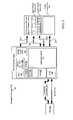
- FIG. 2illustrates a block diagram of one embodiment of an electronic system having a processing device for recognizing a tap gesture.
- Electronic system 200includes processing device 210 , touch-sensor pad 220 , touch-sensor 230 , touch-sensor buttons 240 , host processor 250 , embedded controller 260 , and non-capacitance sensor elements 270 .
- the processing device 210may include analog and/or digital general purpose input/output (“GPIO”) ports 207 .
- GPIO ports 207may be programmable.
- GPIO ports 207may be coupled to a Programmable Interconnect and Logic (“PIL”), which acts as an interconnect between GPIO ports 207 and a digital block array of the processing device 210 (not illustrated).
- PILProgrammable Interconnect and Logic
- the digital block arraymay be configured to implement a variety of digital logic circuits (e.g., DAC, digital filters, digital control systems, etc.) using, in one embodiment, configurable user modules (“UMs”).
- the digital block arraymay be coupled to a system bus.
- Processing device 210may also include memory, such as random access memory (RAM) 205 and program flash 204 .
- RAM 205may be static RAM (SRAM), and program flash 204 may be a non-volatile storage, which may be used to store firmware (e.g., control algorithms executable by processing core 202 to implement operations described herein).
- Processing device 210may also include a memory controller unit (MCU) 203 coupled to memory and the processing core 202 .
- MCUmemory controller unit
- the processing device 210may also include an analog block array (not illustrated).
- the analog block arrayis also coupled to the system bus.
- Analog block arrayalso may be configured to implement a variety of analog circuits (e.g., ADC, analog filters, etc.) using configurable UMs.
- the analog block arraymay also be coupled to the GPIO 207 .
- capacitance sensor 201may be integrated into processing device 210 .
- Capacitance sensor 201may include analog I/O for coupling to an external component, such as touch-sensor pad 220 , touch-sensor slider 230 , touch-sensor buttons 240 , and/or other devices.
- Capacitance sensor 201 and processing device 202are described in more detail below.
- the embodiments described hereinare not limited to touch-sensor pads for notebook implementations, but can be used in other capacitive sensing implementations, for example, the sensing device may be a touch-slider 230 , or a touch-sensor 240 (e.g., capacitance sensing button).
- the operations described hereinare not limited to notebook cursor operations, but can include other operations, such as lighting control (dimmer), volume control, graphic equalizer control, speed control, or other control operations requiring gradual adjustments.
- these embodiments of capacitive sensing implementationsmay be used in conjunction with non-capacitive sensing elements, including but not limited to pick buttons, sliders (ex. display brightness and contrast), scroll-wheels, multi-media control (ex. volume, track advance, etc) handwriting recognition and numeric keypad operation.
- the electronic system 200includes a touch-sensor pad 220 coupled to the processing device 210 via bus 221 .
- Touch-sensor pad 220may include a multi-dimension sensor array.
- the multi-dimension sensor arraycomprises a plurality of sensor elements, organized as rows and columns.
- the electronic system 200includes a touch-sensor slider 230 coupled to the processing device 210 via bus 231 .
- Touch-sensor slider 230may include a single-dimension sensor array.
- the single-dimension sensor arraycomprises a plurality of sensor elements, organized as rows, or alternatively, as columns.
- the electronic system 200includes a touch-sensor button 240 coupled to the processing device 210 via bus 241 .
- Touch-sensor button 240may include a single-dimension or multi-dimension sensor array.
- the single- or multi-dimension sensor arraycomprises a plurality of sensor elements.
- the plurality of sensor elementsmay be coupled together to detect a presence of a conductive object over the entire surface of the sensing device.
- Capacitance sensor elementsmay be used as non-contact switches. These switches, when protected by an insulating layer, offer resistance to severe environments.
- the electronic system 200may include any combination of one or more of the touch-sensor pad 220 , touch-sensor slider 230 , and/or touch-sensor button 240 .
- the electronic system 200may also include non-capacitance sensor elements 270 coupled to the processing device 210 via bus 271 .
- the non-capacitance sensor elements 270may include buttons, light emitting diodes (LEDs), and other user interface devices, such as a mouse, a keyboard, or other functional keys that do not require capacitance sensing.
- buses 271 , 241 , 231 , and 221may be a single bus. Alternatively, these buses may be configured into any combination of one or more separate buses.
- the processing devicemay also provide value-add functionality such as keyboard control integration, LEDs, battery charger and general purpose I/O, as illustrated as non-capacitance sensor elements 270 .
- Non-capacitance sensor elements 270are coupled to the GPIO 207 .
- Processing device 210may include internal oscillator/clocks 206 , and communication block 208 .
- the oscillator/clocks block 206provides clock signals to one or more of the components of processing device 210 .
- Communication block 208may be used to communicate with an external component, such as a host processor 250 , via host interface (I/F) line 251 .
- processing block 210may also be coupled to embedded controller 260 to communicate with the external components, such as host 250 .
- Interfacing to the host 205can be through various methods. In one exemplary embodiment, interfacing with the host 250 may be done using a standard PS/2 interface to connect to an embedded controller 260 , which in turn sends data to the host 250 via low pin count (LPC) interface.
- LPClow pin count
- interfacingmay be done using a universal serial bus (USB) interface directly coupled to the host 250 via host interface line 251 .
- the processing device 210may communicate to external components, such as the host 250 using industry standard interfaces, such as USB, PS/2, inter-integrated circuit (I2C) bus, or system packet interface (SPI).
- the embedded controller 260 and/or embedded controller 260may be coupled to the processing device 210 with a ribbon or flex cable from an assembly, which houses the touch-sensor pad and processing device.
- the processing device 210is configured to communicate with the embedded controller 260 or the host 250 to send data.
- the datamay be a command or alternatively a signal.
- the electronic system 200may operate in both standard-mouse compatible and enhanced modes.
- the standard-mouse compatible modeutilizes the HID class drivers already built into the Operating System (OS) software of host 250 . These drivers enable the processing device 210 and sensing device to operate as a standard cursor control user interface device, such as a two-button PS/2 mouse.
- the enhanced modemay enable additional features such as scrolling (reporting absolute position) or disabling the sensing device, such as when a mouse is plugged into the notebook.
- the processing device 210may be configured to communicate with the embedded controller 260 or the host 250 , using non-OS drivers, such as dedicated touch-sensor pad drivers, or other drivers known by those of ordinary skill in the art.
- the processing device 210may operate to communicate data (e.g., via commands or signals) using hardware, software, and/or firmware, and the data may be communicated directly to the processing device of the host 250 , such as a host processor, or alternatively, may be communicated to the host 250 via drivers of the host 250 , such as OS drivers, or other non-OS drivers. It should also be noted that the host 250 may directly communicate with the processing device 210 via host interface 251 .
- the data sent to the host 250 from the processing device 210includes click, double-click, movement of the cursor, scroll-up, scroll-down, scroll-left, scroll-right, step Back, and step Forward.
- other user interface device commandsmay be communicated to the host 250 from the processing device 210 . These commands may be based on gestures occurring on the sensing device that are recognized by the processing device, such as tap, push, hop, and zigzag gestures. Alternatively, other commands may be recognized. Similarly, signals may be sent that indicate the recognition of these operations.
- a tap gesturemay be when the finger (e.g., conductive object) is on the sensing device for less than a threshold time. If the time the finger is placed on the touchpad is greater than the threshold time it may be considered to be a movement of the cursor, in the x- or y-axes. Scroll-up, scroll-down, scroll-left, and scroll-right, step back, and step-forward may be detected when the absolute position of the conductive object is within a pre-defined area, and movement of the conductive object is detected.
- Processing device 210may reside on a common carrier substrate such as, for example, an integrated circuit (IC) die substrate, a multi-chip module substrate, or the like. Alternatively, the components of processing device 210 may be one or more separate integrated circuits and/or discrete components. In one exemplary embodiment, processing device 210 may be a Programmable System on a Chip (PSoCTM) processing device, manufactured by Cypress Semiconductor Corporation, San Jose, Calif. Alternatively, processing device 210 may be other one or more processing devices known by those of ordinary skill in the art, such as a microprocessor or central processing unit, a controller, special-purpose processor, digital signal processor (DSP), an application specific integrated circuit (ASIC), a field programmable gate array (FPGA), or the like. In an alternative embodiment, for example, the processing device may be a network processor having multiple processors including a core unit and multiple microengines. Additionally, the processing device may include any combination of general-purpose processing device(s) and special-purpose processing device(s).
- POPTMProgrammable
- Capacitance sensor 201may be integrated into the IC of the processing device 210 , or alternatively, in a separate IC. Alternatively, descriptions of capacitance sensor 201 may be generated and compiled for incorporation into other integrated circuits. For example, behavioral level code describing capacitance sensor 201 , or portions thereof, may be generated using a hardware descriptive language, such as VHDL or Verilog, and stored to a machine-accessible medium (e.g., CD-ROM, hard disk, floppy disk, etc.). Furthermore, the behavioral level code can be compiled into register transfer level (“RTL”) code, a netlist, or even a circuit layout and stored to a machine-accessible medium. The behavioral level code, the RTL code, the netlist, and the circuit layout all represent various levels of abstraction to describe capacitance sensor 201 .
- VHDLhardware descriptive language
- Verilogmachine-accessible medium
- the behavioral level codecan be compiled into register transfer level (“RTL”) code, a netlist, or even a circuit
- electronic system 200may include all the components described above. Alternatively, electronic system 200 may include only some of the components described above.
- electronic system 200may be used in a notebook computer.
- the electronic devicemay be used in other applications, such as a mobile handset, a personal data assistant (PDA), a keyboard, a television, a remote control, a monitor, a handheld multi-media device, a handheld video player, a handheld gaming device, or a control panel.
- PDApersonal data assistant
- capacitance sensor 201may be a capacitive switch relaxation oscillator (CSR).
- CSRcapacitive switch relaxation oscillator
- the CSRmay have an array of capacitive touch switches using a current-programmable relaxation oscillator, an analog multiplexer, digital counting functions, and high-level software routines to compensate for environmental and physical switch variations.
- the switch arraymay include combinations of independent switches, sliding switches (e.g., touch-sensor slider), and touch-sensor pads implemented as a pair of orthogonal sliding switches.
- the CSRmay include physical, electrical, and software components.
- the physical componentmay include the physical switch itself, typically a pattern constructed on a printed circuit board (PCB) with an insulating cover, a flexible membrane, or a transparent overlay.
- PCBprinted circuit board
- the electrical componentmay include an oscillator or other means to convert a changed capacitance into a measured signal.
- the electrical componentmay also include a counter or timer to measure the oscillator output.
- the software componentmay include detection and compensation software algorithms to convert the count value into a switch detection decision. For example, in the case of slide switches or X-Y touch-sensor pads, a calculation for finding position of the conductive object to greater resolution than the physical pitch of the switches may be used.
- the current versus voltage phase shift measurementmay include driving the capacitance through a fixed-value resistor to yield voltage and current waveforms that are out of phase by a predictable amount.
- the drive frequencycan be adjusted to keep the phase measurement in a readily measured range.
- the resistor-capacitor charge timingmay include charging the capacitor through a fixed resistor and measuring timing on the voltage ramp. Small capacitor values may require very large resistors for reasonable timing.
- the capacitive bridge dividermay include driving the capacitor under test through a fixed reference capacitor. The reference capacitor and the capacitor under test form a voltage divider.
- the voltage signalis recovered with a synchronous demodulator, which may be done in the processing device 210 .
- the charge transfermay be conceptually similar to an R-C charging circuit.
- C Pis the capacitance being sensed.
- C SUMis the summing capacitor, into which charge is transferred on successive cycles. At the start of the measurement cycle, the voltage on C SUM is reset. The voltage on C SUM increases exponentially (and only slightly) with each clock cycle. The time for this voltage to reach a specific threshold is measured with a counter. Additional details regarding these alternative embodiments have not been included so as to not obscure the present embodiments, and because these alternative embodiments for measuring capacitance are known by those of ordinary skill in the art.
- FIG. 3Aillustrates a varying switch capacitance.
- a capacitive switch 300is a pair of adjacent plates 301 and 302 .
- a conductive object 303e.g., finger
- Capacitive switch 300may be used in a capacitance switch array.
- the capacitance switch arrayis a set of capacitors where one side of each is grounded.
- the active capacitoras represented in FIG. 3B as capacitor 351
- the presence of the conductive object 303increases the capacitance (Cp+Cf) of the switch 300 to ground. Determining switch activation is then a matter of measuring change in the capacitance (Cf).
- Switch 300is also known as a grounded variable capacitor.
- Cfmay range from approximately 10-30 picofarads (pF). Alternatively, other ranges may be used.
- the conductive object in this caseis a finger
- this techniquemay be applied to any conductive object, for example, a conductive door switch, position sensor, or conductive pen in a stylus tracking system.
- FIG. 3Billustrates one embodiment of a relaxation oscillator.
- the relaxation oscillator 350is formed by the capacitance to be measured on capacitor 351 , a charging current source 352 , a comparator 353 , and a reset switch 354 .
- capacitor 351is representative of the capacitance measured on a sensor element of a sensor array.
- the relaxation oscillatoris coupled to drive a charging current (Ic) 357 in a single direction onto a device under test (“DUT”) capacitor, capacitor 351 .
- Iccharging current
- DUTdevice under test
- Equation (1)describes the relation between current, capacitance, voltage and time for a charging capacitor.
- CdVI c dt (1)
- the relaxation oscillatorbegins by charging the capacitor 351 from a ground potential or zero voltage and continues to pile charge on the capacitor 351 at a fixed charging current Ic 357 until the voltage across the capacitor 351 at node 355 reaches a reference voltage or threshold voltage, V TH 355 .
- V TH 355the relaxation oscillator allows the accumulated charge at node 355 to discharge (e.g., the capacitor 351 to “relax” back to the ground potential) and then the process repeats itself.
- the output of comparator 353asserts a clock signal F OUT 356 (e.g., F OUT 356 goes high), which enables the reset switch 354 . This resets the voltage on the capacitor at node 355 to ground and the charge cycle starts again.
- the relaxation oscillatoroutputs a relaxation oscillator clock signal (F OUT 356 ) having a frequency (f RO ) dependent upon capacitance C of the capacitor 351 and charging current Ic 357 .
- the comparator trip time of the comparator 353 and reset switch 354add a fixed delay.
- the output of the comparator 353is synchronized with a reference system clock to guarantee that the comparator reset time is long enough to completely reset the charging voltage on capacitor 355 .
- f RO of F OUT 356against the frequency (f REF ) of a known reference system clock signal (REF CLK)
- a frequency comparatormay be coupled to receive relaxation oscillator clock signal (F OUT 356 ) and REF CLK, compare their frequencies f RO and f REF , respectively, and output a signal indicative of the difference ⁇ f between these frequencies. By monitoring ⁇ f one can determine whether the capacitance of the capacitor 351 has changed.
- the relaxation oscillator 350may be built using a 555 timer to implement the comparator 353 and reset switch 354 .
- the relaxation oscillator 350may be built using other circuiting. Relaxation oscillators are known in by those of ordinary skill in the art, and accordingly, additional details regarding their operation have not been included so as to not obscure the present embodiments.
- FIG. 4illustrates a block diagram of one embodiment of a capacitance sensor including a relaxation oscillator and digital counter.
- Capacitance sensor 201 of FIG. 4includes a sensor array 410 (also known as a switch array), relaxation oscillator 350 , and a digital counter 420 .
- Sensor array 410includes a plurality of sensor elements 355 ( 1 )- 355 (N), where N is a positive integer value that represents the number of rows (or alternatively columns) of the sensor array 410 .
- Each sensor elementis represented as a capacitor, as previously described with respect to FIG. 3B .
- the sensor array 410is coupled to relaxation oscillator 350 via an analog bus 401 having a plurality of pins 401 ( 1 )- 401 (N).
- the sensor array 410may be a single-dimension sensor array including the sensor elements 355 ( 1 )- 355 (N), where N is a positive integer value that represents the number of sensor elements of the single-dimension sensor array.
- the single-dimension sensor array 410provides output data to the analog bus 401 of the processing device 210 (e.g., via lines 231 ).
- the sensor array 410may be a multi-dimension sensor array including the sensor elements 355 ( 1 )- 355 (N), where N is a positive integer value that represents the number of sensor elements of the multi-dimension sensor array.
- the multi-dimension sensor array 410provides output data to the analog bus 401 of the processing device 210 (e.g., via bus 221 ).
- Relaxation oscillator 350 of FIG. 4includes all the components described with respect to FIG. 3B , and a selection circuit 430 .
- the selection circuit 430is coupled to the plurality of sensor elements 355 ( 1 )- 355 (N), the reset switch 354 , the current source 352 , and the comparator 353 .
- Selection circuit 430may be used to allow the relaxation oscillator 350 to measure capacitance on multiple sensor elements (e.g., rows or columns).
- the selection circuit 430may be configured to sequentially select a sensor element of the plurality of sensor elements to provide the charge current and to measure the capacitance of each sensor element.
- the selection circuit 430is a multiplexer array of the relaxation oscillator 350 .
- selection circuitmay be other circuitry outside the relaxation oscillator 350 , or even outside the capacitance sensor 201 to select the sensor element to be measured.
- Capacitance sensor 201may include one relaxation oscillator and digital counter for the plurality of sensor elements of the sensor array.
- capacitance sensor 201may include multiple relaxation oscillators and digital counters to measure capacitance on the plurality of sensor elements of the sensor array.
- the multiplexer arraymay also be used to ground the sensor elements that are not being measured. This may be done in conjunction with a dedicated pin in the GP10 port 207 .
- the capacitance sensor 201may be configured to simultaneously scan the sensor elements, as opposed to being configured to sequentially scan the sensor elements as described above.
- the sensing devicemay include a sensor array having a plurality of rows and columns. The rows may be scanned simultaneously, and the columns may be scanned simultaneously.
- the voltages on all of the rows of the sensor arrayare simultaneously moved, while the voltages of the columns are held at a constant voltage, with the complete set of sampled points simultaneously giving a profile of the conductive object in a first dimension.
- the voltages on all of the rowsare held at a constant voltage, while the voltages on all the rows are simultaneously moved, to obtain a complete set of sampled points simultaneously giving a profile of the conductive object in the other dimension.
- the voltages on all of the rows of the sensor arrayare simultaneously moved in a positive direction, while the voltages of the columns are moved in a negative direction.
- the voltages on all of the rows of the sensor arrayare simultaneously moved in a negative direction, while the voltages of the columns are moved in a positive direction.
- Digital counter 420is coupled to the output of the relaxation oscillator 350 .
- Digital counter 420receives the relaxation oscillator output signal 356 (F OUT ).
- Digital counter 420is configured to count at least one of a frequency or a period of the relaxation oscillator output received from the relaxation oscillator.
- the relaxation oscillator output signal 356(F OUT ) is fed to the digital counter 420 for measurement.
- the digital counter 420may include two multiplexers 423 and 424 . Multiplexers 423 and 424 are configured to select the inputs for the PWM 421 and the timer 422 for the two measurement methods, frequency and period measurement methods.
- multiplexers 423 and 424are not included in the digital counter, for example, the digital counter 420 may be configured in one, or the other, measurement configuration.
- the relaxation oscillator output signal 356is counted for a fixed period of time.
- the counter 422is read to obtain the number of counts during the gate time. This method works well at low frequencies where the oscillator reset time is small compared to the oscillator period.
- a pulse width modulator (PWM) 441is clocked for a fixed period by a derivative of the system clock, VC 3 426 (which is a divider from the 24 MHz system clock 425 ). Pulse width modulation is a modulation technique that generates variable-length pulses to represent the amplitude of an analog input signal; in this case VC 3 426 .
- the output of PWM 421enables timer 422 (e.g., 16-bit).
- the relaxation oscillator output signal 356clocks the timer 422 .
- the timer 422is reset at the start of the sequence, and the count value is read out at the end of the gate period.
- the relaxation oscillator output signal 356gates a counter 422 , which is clocked by the system clock 425 (e.g., 24 MHz). In order to improve sensitivity and resolution, multiple periods of the oscillator are counted with the PWM 421 . The output of PWM 421 is used to gate the timer 422 . In this method, the relaxation oscillator output signal 356 drives the clock input of PWM 421 .
- pulse width modulationis a modulation technique that generates variable-length pulses to represent the amplitude of an analog input signal; in this case the relaxation oscillator output signal 356 .
- the output of the PWM 421enables a timer 422 (e.g., 16-bit), which is clocked at the system clock frequency 425 (e.g., 24 MHz).
- a timer 422e.g., 16-bit
- the countstarts by releasing the capture control.
- the capture signalis asserted (e.g., goes high), stopping the count and setting the PWM's interrupt.
- the timer valueis read in this interrupt.
- the relaxation oscillator 350is indexed to the next switch (e.g., capacitor 351 ( 2 )) to be measured and the count sequence is started again.
- the two counting methodsmay have equivalent performance in sensitivity and signal-to-noise ratio (SNR).
- the period measurement methodmay have a slightly faster data acquisition rate, but this rate is dependent on software load and the values of the switch capacitances.
- the frequency measurement methodhas a fixed-switch data acquisition rate.
- the length of the counter 422 and the detection time required for the switchare determined by sensitivity requirements. Small changes in the capacitance on capacitor 351 result in small changes in frequency. In order to find these small changes, it may be necessary to count for a considerable time.
- the switchese.g., capacitors 351 ( 1 )-(N)
- the count values for each switch with no actuationare stored as a baseline array (Cp).
- the presence of a finger on the switchis determined by the difference in counts between a stored value for no switch actuation and the acquired value with switch actuation, referred to here as ⁇ n.
- the sensitivity of a single switchis approximately:
- ⁇ nThe value of ⁇ n should be large enough for reasonable resolution and clear indication of switch actuation. This drives switch construction decisions.
- Cfshould be as large a fraction of Cp as possible.
- the fraction of Cf/Cpranges between approximately 0.01 to approximately 2.0. Alternatively, other fractions may be used for Cf/Cp. Since Cf is determined by finger area and distance from the finger to the switch's conductive traces (through the over-lying insulator), the baseline capacitance Cp should be minimized.
- the baseline capacitance Cpincludes the capacitance of the switch pad plus any parasitics, including routing and chip pin capacitance.
- the PCB designmay be adapted to minimize capacitance, including thicker PCBs where possible.
- thicker PCBsIn one exemplary embodiment, a 0.062 inch thick PCB is used. Alternatively, other thicknesses may be used, for example, a 0.015 inch thick PCB.
- the count windowshould be long enough for ⁇ n to be a “significant number.”
- the “significant number”can be as little as 10, or alternatively, as much as several hundred.
- Cfis 1.0% of Cp (a typical “weak” switch)
- the switch thresholdis set at a count value of 20
- the detection time for the switchis 4 microseconds.
- the frequency difference between a switch with and without actuationi.e., CP+CF vs. CP
- the count difference between a switch with and without actuationi.e., CP+CF vs. CP
- the charge currentsare typically lower and the period is longer to increase sensitivity, or the number of periods for which f SysClk is counted can be increased.
- the repeatability of detectionincreases, making all switches work at the same difference. Compensation for this variation can be done in software at runtime.
- the compensation algorithms for both the frequency method and period methodmay be included in the high-level APIs.
- this circuituses a current source programmed by a fixed-resistor value. If the range of capacitance to be measured changes, external components, (i.e., the resistor) should be adjusted.
- multiple sensor elementsmay be sequentially scanned to provide current to and measure the capacitance from the capacitors (e.g., sensor elements), as previously described. In other words, while one sensor element is being measured, the remaining sensor elements are grounded using the GPIO port 207 .
- This drive and multiplex arrangementbypasses the existing GPIO to connect the selected pin to an internal analog multiplexer (mux) bus.
- the capacitor charging current (e.g., current source 352 ) and reset switch 353are connected to the analog mux bus. This may limit the pin-count requirement to simply the number of switches (e.g., capacitors 351 ( 1 )- 351 (N)) to be addressed. In one exemplary embodiment, no external resistors or capacitors are required inside or outside the processing device 210 to enable operation.
- the capacitor charging current for the relaxation oscillator 350is generated in a register programmable current output DAC (also known as IDAC). Accordingly, the current source 352 is a current DAC or IDAC.
- the IDAC output currentmay be set by an 8-bit value provided by the processing device 210 , such as from the processing core 202 .
- the 8-bit valuemay be stored in a register or in memory.
- the oscillator-reset timemay add to the oscillator period (especially at higher frequencies); and there may be some variation to the magnitude of the IDAC output current with operating frequency. Accordingly, the optimum oscillation frequency and operating current for a particular switch array may be determined to some degree by experimentation.
- the two “plates” (e.g., 301 and 302 ) of the sensing capacitorare actually adjacent PCB pads or traces, as indicated in FIG. 3A .
- one of these platesis grounded.
- Layouts for touch-sensor slider (e.g., linear slide switches) and touch-sensor pad applicationshave switches that are immediately adjacent. In this case, all of the switches that are not active are grounded through the GPIO 207 of the processing device 210 dedicated to that pin.
- the actual capacitance between adjacent platesis small (Cp), but the capacitance of the active plate (and its PCB trace back to the processing device 210 ) to ground, when detecting the presence of the conductive object 303 , may be considerably higher (Cp+Cf).
- the capacitance of two parallel platesis given by the following equation:
- equation (8)The dimensions of equation (8) are in meters. This is a very simple model of the capacitance. The reality is that there are fringing effects that substantially increase the switch-to-ground (and PCB trace-to-ground) capacitance.
- Switch sensitivitymay be increased by one or more of the following: 1) increasing board thickness to increase the distance between the active switch and any parasitics; 2) minimizing PC trace routing underneath switches; 3) utilizing a grided ground with 50% or less fill if use of a ground plane is absolutely necessary; 4) increasing the spacing between switch pads and any adjacent ground plane; 5) increasing pad area; 6) decreasing thickness of any insulating overlay; or 7) verifying that there is no air-gap between the PC pad surface and the touching finger.
- a baseline update routinewhich compensates for this variation, may be provided in the high-level APIs.
- Sliding switchesare used for control requiring gradual adjustments. Examples include a lighting control (dimmer), volume control, graphic equalizer, and speed control. These switches are mechanically adjacent to one another. Actuation of one switch results in partial actuation of physically adjacent switches. The actual position in the sliding switch is found by computing the centroid location of the set of switches activated.
- the arrayis first scanned to verify that a given switch location is valid. The requirement is for some number of adjacent switch signals to be above a noise threshold. When the strongest signal is found, this signal and those immediately adjacent are used to compute a centroid:
- Centroidn i - 1 ⁇ ( i - 1 ) + n i ⁇ i + n i + 1 ⁇ ( i + 1 ) n i - 1 + n i ⁇ i + n i + 1 ( 9 )
- centroid valuemay be multiplied by a calculated scalar. It may be more efficient to combine the interpolation and scaling operations into a single calculation and report this result directly in the desired scale. This may be handled in the high-level APIs. Alternatively, other methods may be used to interpolate the position of the conductive object.
- a physical touchpad assemblyis a multi-layered module to detect a conductive object.
- the multi-layer stack-up of a touchpad assemblyincludes a PCB, an adhesive layer, and an overlay.
- the PCBincludes the processing device 210 and other components, such as the connector to the host 250 , necessary for operations for sensing the capacitance. These components are on the non-sensing side of the PCB.
- the PCBalso includes the sensor array on the opposite side, the sensing side of the PCB.
- other multi-layer stack-upsmay be used in the touchpad assembly.
- the PCBmay be made of standard materials, such as FR4 or KaptonTM (e.g., flexible PCB). In either case, the processing device 210 may be attached (e.g., soldered) directly to the sensing PCB (e.g., attached to the non-sensing side of the PCB).
- the PCB thicknessvaries depending on multiple variables, including height restrictions and sensitivity requirements. In one embodiment, the PCB thickness is at least approximately 0.3 millimeters (mm). Alternatively, the PCB may have other thicknesses. It should be noted that thicker PCBs may yield better results.
- the PCB length and widthis dependent on individual design requirements for the device on which the sensing device is mounted, such as a notebook or mobile handset.
- the adhesive layeris directly on top of the PCB sensing array and is used to affix the overlay to the overall touchpad assembly.
- Typical material used for connecting the overlay to the PCBis non-conductive adhesive such as 3M 467 or 468.
- the adhesive thicknessis approximately 0.05 mm. Alternatively, other thicknesses may be used.
- the overlaymay be non-conductive material used to protect the PCB circuitry to environmental elements and to insulate the user's finger (e.g., conductive object) from the circuitry.
- Overlaycan be ABS plastic, polycarbonate, glass, or MylarTM. Alternatively, other materials known by those of ordinary skill in the art may be used.
- the overlayhas a thickness of approximately 1.0 mm. In another exemplary embodiment, the overlay thickness has a thickness of approximately 2.0 mm. Alternatively, other thicknesses may be used.
- the sensor arraymay be a grid-like pattern of sensor elements (e.g., capacitive elements) used in conjunction with the processing device 210 to detect a presence of a conductive object, such as finger, to a resolution greater than that which is native.
- sensor elementse.g., capacitive elements
- the touch-sensor pad layout patternmaximizes the area covered by conductive material, such as copper, in relation to spaces necessary to define the rows and columns of the sensor array.
- FIG. 5Aillustrates a top-side view of one embodiment of a sensor array having a plurality of sensor elements for detecting a presence of a conductive object 303 on the sensor array 500 of a touch-sensor pad.
- Touch-sensor pad 220includes a sensor array 500 .
- Sensor array 500includes a plurality of rows 504 ( 1 )- 504 (N) and a plurality of columns 505 ( 1 )- 505 (M), where N is a positive integer value representative of the number of rows and M is a positive integer value representative of the number of columns.
- Each rowincludes a plurality of sensor elements 503 ( 1 )- 503 (K), where K is a positive integer value representative of the number of sensor elements in the row.
- Each columnincludes a plurality of sensor elements 501 ( 1 )- 501 (L), where L is a positive integer value representative of the number of sensor elements in the column.
- sensor arrayis an N ⁇ M sensor matrix.
- the N ⁇ M sensor matrixin conjunction with the processing device 210 , is configured to detect a position of a presence of the conductive object 303 in the x-, and y-directions.
- FIG. 5Billustrates a top-side view of one embodiment of a sensor array having a plurality of sensor elements for detecting a presence of a conductive object 303 on the sensor array 550 of a touch-sensor slider.
- Touch-sensor slider 230includes a sensor array 550 .
- Sensor array 550includes a plurality of columns 504 ( 1 )- 504 (M), where M is a positive integer value representative of the number of columns.
- Each columnincludes a plurality of sensor elements 501 ( 1 )- 501 (L), where L is a positive integer value representative of the number of sensor elements in the column. Accordingly, sensor array is a 1 ⁇ M sensor matrix.
- the 1 ⁇ M sensor matrixin conjunction with the processing device 210 , is configured to detect a position of a presence of the conductive object 303 in the x-direction. It should be noted that sensor array 500 may be configured to function as a touch-sensor slider 230 .
- Alternating columns in FIG. 5Acorrespond to x- and y-axis elements.
- the y-axis sensor elements 503 ( 1 )- 503 (K)are illustrated as black diamonds in FIG. 5A
- the x-axis sensor elements 501 ( 1 )- 501 (L)are illustrated as white diamonds in FIG. 5A and FIG. 5B .
- the columns and rowmay include vertical and horizontal bars (e.g., rectangular shaped bars), however, this design may include additional layers in the PCB to allow the vertical and horizontal bars to be positioned on the PCB so that they are not in contact with one another.
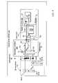
- FIGS. 5C and 5Dillustrate top-side and side views of one embodiment of a two-layer touch-sensor pad.
- Touch-sensor padas illustrated in FIGS. 5C and 5D , include the first two columns 505 ( 1 ) and 505 ( 2 ), and the first four rows 504 ( 1 )- 504 ( 4 ) of sensor array 500 .
- the sensor elements of the first column 501 ( 1 )are connected together in the top conductive layer 575 , illustrated as hashed diamond sensor elements and connections.
- the diamond sensor elements of each columnin effect, form a chain of elements.
- the sensor elements of the second column 501 ( 2 )are similarly connected in the top conductive layer 575 .
- the sensor elements of the first row 504 ( 1 )are connected together in the bottom conductive layer 575 using vias 577 , illustrated as black diamond sensor elements and connections.
- the diamond sensor elements of each rowin effect, form a chain of elements.
- the sensor elements of the second, third, and fourth rows 504 ( 2 )- 504 ( 4 )are similarly connected in the bottom conductive layer 576 .
- the top conductive layer 575includes the sensor elements for both the columns and the rows of the sensor array, as well as the connections between the sensor elements of the columns of the sensor array.
- the bottom conductive layer 576includes the conductive paths that connect the sensor elements of the rows that reside in the top conductive layer 575 .
- the conductive paths between the sensor elements of the rowsuse vias 577 to connect to one another in the bottom conductive layer 576 .
- Vias 577go from the top conductive layer 575 , through the dielectric layer 578 , to the bottom conductive layer 576 .
- Coating layers 579 and 589are applied to the surfaces opposite to the surfaces that are coupled to the dielectric layer 578 on both the top and bottom conductive layers 575 and 576 .
- present embodimentsshould not be limited to connecting the sensor elements of the rows using vias to the bottom conductive layer 576 , but may include connecting the sensor elements of the columns using vias to the bottom conductive layer 576 .
- pinsWhen pins are not being sensed (only one pin is sensed at a time), they are routed to ground.
- the sensing devicee.g., touch-sensor pad
- the exterior elementsBy surrounding the sensing device (e.g., touch-sensor pad) with a ground plane, the exterior elements have the same fringe capacitance to ground as the interior elements.
- an IC including the processing device 210may be directly placed on the non-sensor side of the PCB. This placement does not necessary have to be in the center.
- the processing device ICis not required to have a specific set of dimensions for a touch-sensor pad, nor a certain number of pins. Alternatively, the IC may be placed somewhere external to the PCB.
- FIG. 6illustrates a block diagram of one embodiment of a sensing device including a switch circuit.
- Sensing device 610includes switch circuit 620 and a plurality of sensor elements 601 ( 1 )- 601 (N), where N is a positive integer value representative of a total number of the plurality of sensor elements of the sensing device 610 .
- Sensor elements 601 ( 1 )- 601 (N)are coupled to the switch circuit 620 .
- Sensing device 610is coupled to processing device 210 .
- processing device 210includes a plurality of pins 602 ( 1 )- 602 (L), where L is a positive integer value equal to the number of pins, and the switch circuit 620 is coupled to the plurality of pins 602 ( 1 )- 602 (L).
- Sensor elements 601 ( 1 )- 601 (N)are illustrated as vertical bars (e.g., rectangular shaped bars. It should be noted that other shapes may be used for the sensor elements, such as diamond shapes, as described above. These sensor elements 601 ( 1 )- 601 (N) may be part of a multi-dimension sensor array, or alternatively, of a single dimension sensor array.
- the sensor arraymay be one dimensional, detecting movement in one axis.
- the sensor arraymay also be two dimensional, detecting movements in two axes.
- the multi-dimension sensor arraycomprises a plurality of sensor elements, organized as rows and columns, and may be used in a touch-sensor pad (e.g., 220 ).
- the single-dimension sensor arraycomprises a plurality of sensor elements, organized as rows, or alternatively, as columns, and may be used in a touch-sensor slider (e.g., 230 ).
- Sensor elements 601 ( 1 )- 601 (N)are configured to detect a presence of a conductive object 303 on the sensing device 610 .
- the switch circuit 620is configured to group the plurality of sensor elements 601 ( 1 )- 601 (N) into multiple first scan groups and a second scan group.
- the processing device 210includes one or more capacitance sensors 201 coupled to the circuit switch 620 via pins 602 ( 1 )- 602 (L).
- the capacitance sensorsare configured to measure capacitance on the plurality of sensor elements 601 ( 1 )- 601 (N).
- the switch circuitmay include first and second settings.
- the first settingis configured to couple each capacitance sensor of the one or more capacitance sensors of the processing device 210 to a first scan group of the multiple first scan groups. Each sensor element of the each first scan group is coupled together.
- the second settingis configured to couple the one or more capacitance sensors to two or more sensor elements of a selected first scan group.
- Each first scan groupincludes a number of sensor elements that is equal to ⁇ square root over (N) ⁇ , where N is a positive integer value representative of a total number of the plurality of sensor elements 601 ( 1 )- 601 (N) of the sensing device 610 .
- the embodiments described hereinmay include the advantage of reducing an average scan rate to detect the position of the conductive object on the sensing device.
- the processing device 210is configured to detect the average scan rate to detect the position is approximately (2 ⁇ square root over (N) ⁇ +1)/2.
- the embodiments described hereininclude N number or sensor elements grouped into ⁇ square root over (N) ⁇ , each group having ⁇ square root over (N) ⁇ sensor elements.
- Nmaximally ⁇ square root over (N) ⁇ cycles are needed to scan ⁇ square root over (N) ⁇ groups (e.g., coarse scan).
- maximally ⁇ square root over (N) ⁇ cyclesare needed to scan ⁇ square root over (N) ⁇ sensor elements (e.g., fine scan). Accordingly, the scan rate is 2 ⁇ square root over (N) ⁇ .
- the switch circuitis configured to dynamically partition the second scan group (e.g., fine scan group) such that the contact point (e.g., sensor element that detects the presence of the conductive object) is in the center of the second scan group.
- the average scan rateis approximately (2 ⁇ square root over (N) ⁇ +1)/2.
- the processing device 210may perform a first scan, on average, in approximately ( ⁇ square root over (N) ⁇ +1)/2, and the second scan, on average, in approximately ( ⁇ square root over (N) ⁇ +1)/2, resulting in an average scan rate of approximately (2 ⁇ square root over (N) ⁇ +1)/2.
- FIG. 7Aillustrates a block diagram of one exemplary embodiment of a switch circuit.
- the switch circuit 720is coupled to 4 sensor elements 701 ( 1 )- 701 ( 4 ) of sensing device 610 , and two capacitance sensors 703 ( 1 )- 703 ( 2 ) of processing device 210 via pins 702 ( 1 ) and 702 ( 2 ).
- the processing device 210is configured to detect the presence of the conductive object 303 on the sensing device 610 .
- the processing device 210may sequentially scan the sensor elements 701 ( 1 )- 701 ( 4 ) to determine the capacitance variation on the sensor elements to detect the presence and/or the position of the conductive object 303 on the sensing device 610 .
- the switch circuit 720may be configured in first or second settings 710 and 720 , respectively. First setting 710 and second setting 730 are illustrated and described with respect to FIG. 7B and FIG. 7C , respectively.
- FIG. 7Billustrates a block diagram of the switch circuit of FIG. 7A in a first setting.
- switch circuit 720is configured to couple capacitance sensors 703 ( 1 ) and 703 ( 2 ) to groups of sensor elements, groups 704 and 705 .
- the first group 704includes the first and second sensor elements 701 ( 1 ) and 701 ( 2 ).
- the second group 705includes the third and fourth sensor elements 701 ( 3 ) and 701 ( 4 ).
- the sensor elements of each groupare coupled together (e.g., coupled to the same capacitance sensor).
- the processing device 210scans the two groups 704 and 705 during the first scan using capacitance sensors 703 ( 1 ) and 703 ( 2 ), and detects the presence of the conductive object 303 in the first area using the capacitance sensors 703 ( 1 ) and 703 ( 2 ).
- the first areais less than the area of the sensing device.
- the first areais the area of the group (e.g., 704 ) that detects the presence of the conductive object 303 .
- the processing device 210selects the capacitance sensor (e.g., in this case, capacitance sensor 703 ( 1 )) coupled to the group (e.g., 704 ) that includes the first area in which the presence of the conductive object 303 is detected using the first scan.
- the processing device 210selects the group that includes the first area in which the presence of the conductive object is detected using the first scan.
- Information regarding which capacitance sensor or group is selectedmay be used by the second setting for the second scan, described below.
- FIG. 7Cillustrates a block diagram of the switch circuit of FIG. 7A in a second setting.
- switch circuit 720is configured to couple the capacitance sensors 703 ( 1 ) and 703 ( 2 ) to the two sensor elements 701 ( 1 ) and 701 ( 2 ), respectively, of the selected group 707 .
- the selected group 707may be determined using the information obtained during the first scan regarding the selected group or selected capacitance sensor.
- the selected group 707includes the same sensor elements of the group that detected the presence of the conductive object 303 on the sensing device 610 (e.g., group 704 ).
- the selected group of sensor elementsmay include sensor elements that surround the sensor element that detected the presence of the conductive object 303 , even though one or more of these sensors may belong to a different group during the first scan.
- the selected group 707includes the first and second sensor elements 701 ( 1 ) and 701 ( 2 ).
- the sensor elements of each groupare not coupled together (e.g., not coupled to the same capacitance sensor), but are coupled to individual capacitance sensors.
- capacitance sensor 703 ( 1 )is coupled to sensor element 701 ( 1 )
- capacitance sensor 703 ( 2 )is coupled to sensor element 701 ( 2 ).
- the processing device 210scans the two sensor elements 701 ( 1 ) and 701 ( 2 ) during the second scan using capacitance sensors 703 ( 1 ) and 703 ( 2 ), and detects the presence of the conductive object 303 within the first area using the capacitance sensors 703 ( 1 ) and 703 ( 2 ). The processing device 210 then selects the capacitance sensor (e.g., in this case, capacitance sensor 703 ( 2 )) coupled to the sensor element (e.g., 701 ( 2 )) on which the presence of the conductive object 303 is detected using the second scan.
- the capacitance sensore.g., in this case, capacitance sensor 703 ( 2 )
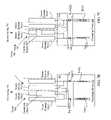
- FIG. 8Aillustrates a block diagram of another exemplary embodiment of a switch circuit.
- the switch circuit 820is coupled to 9 sensor elements 801 ( 1 )- 801 ( 9 ) of sensing device 610 , and three capacitance sensors 803 ( 1 )- 803 ( 8 ) of processing device 210 via pins 802 ( 1 )- 802 ( 3 ).
- the processing device 210is configured to detect the presence of the conductive object 303 on the sensing device 610 .
- the processing device 210may sequentially scan the sensor elements 801 ( 1 )- 801 ( 9 ) to determine the capacitance variation on the sensor elements to detect the presence and/or the position of the conductive object 303 on the sensing device 610 .
- the switch circuit 820may be configured in first or second settings 810 and 820 , respectively. First setting 810 and second setting 820 are illustrated and described with respect to FIG. 8B and FIG. 8C , respectively.
- FIG. 8Billustrates a block diagram of the switch circuit of FIG. 8A in a first setting.
- switch circuit 820is configured to couple capacitance sensors 803 ( 1 )- 803 ( 3 ) to groups of sensor elements, groups 804 , 805 , and 806 , respectively.
- the first group 804includes the first, second, and third sensor elements 801 ( 1 )- 801 ( 3 ).
- the second group 805includes the fourth, fifth, and sixth sensor elements 801 ( 4 )- 801 ( 6 ).
- the third group 806includes the seventh, eighth, and ninth sensor elements 801 ( 7 )- 801 ( 9 ).
- the sensor elements of each groupare coupled together (e.g., coupled to the same capacitance sensor).
- the processing device 210scans the three groups 804 , 805 , and 806 during the first scan using capacitance sensors 803 ( 1 )- 803 ( 3 ), and detects the presence of the conductive object 303 in the first area using the capacitance sensors 803 ( 1 )- 803 ( 3 ).
- the first areais less than the area of the sensing device.
- the first areais the area of the group (e.g., 805 ) that detects the presence of the conductive object 303 .
- the processing device 210selects the capacitance sensor (e.g., in this case, capacitance sensor 803 ( 2 )) coupled to the group (e.g., 805 ) that includes the first area in which the presence of the conductive object is detected using the first scan.
- the processing device 210selects the group that includes the first area in which the presence of the conductive object is detected using the first scan.
- Information regarding which capacitance sensor or group is selectedmay be used by the second setting for the second scan, described below.
- FIG. 8Cillustrates a block diagram of the switch circuit of FIG. 8A in a second setting.
- switch circuit 820is configured to couple the capacitance sensors 803 ( 1 )- 803 ( 3 ) to the three sensor elements 801 ( 1 )- 801 ( 3 ), respectively, of the selected group 807 (e.g., fine scan group).
- the selected group 807may be determined using the information obtained during the first scan regarding the selected group or selected capacitance sensor.
- the selected group 807includes the same sensor elements of the group that detected the presence of the conductive object 303 on the sensing device 610 (e.g., group 805 ).
- the selected group of sensor elementsmay include sensor elements that surround the sensor element that detected the presence of the conductive object 303 , even though one or more of these sensors may belong to a different group during the first scan.
- the selected group 807includes the fourth, fifth, and sixth sensor elements 801 ( 3 )- 801 ( 6 ).
- the sensor elements of each groupare not coupled together (e.g., not coupled to the same capacitance sensor), but are coupled to individual capacitance sensors.
- capacitance sensor 803 ( 1 )is coupled to sensor element 801 ( 4 )
- capacitance sensor 803 ( 2 )is coupled to sensor element 801 ( 5 )
- capacitance sensor 803 ( 2 )is coupled to sensor element 801 ( 6 ).
- the processing device 210scans the three sensor elements 801 ( 4 ), 801 ( 5 ), and 801 ( 6 ) during the second scan using capacitance sensors 803 ( 1 ), 803 ( 2 ), and 803 ( 3 ), and detects the presence of the conductive object 303 within the first area using the capacitance sensors 803 ( 1 ), 803 ( 2 ), and 803 ( 3 ).
- the processing device 210selects the capacitance sensor (e.g., in this case, capacitance sensor 803 ( 2 )) coupled to the sensor element (e.g., 801 ( 5 )) on which the presence of the conductive object 303 is detected using the second scan.
- FIG. 9Aillustrates a block diagram of another exemplary embodiment of a switch circuit.
- the switch circuit 920is coupled to 9 sensor elements 901 ( 1 )- 901 ( 9 ) of sensing device 610 , and three capacitance sensors 903 ( 1 )- 903 ( 8 ) of processing device 210 via pins 902 ( 1 )- 902 ( 3 ).
- the processing device 210is configured to detect the presence of the conductive object 303 on the sensing device 610 .
- the processing device 210may sequentially scan the sensor elements 901 ( 1 )- 901 ( 9 ) to determine the capacitance variation on the sensor elements to detect the presence and/or the position of the conductive object 303 on the sensing device 610 .
- the switch circuit 920may be configured in first or second settings 910 and 920 , respectively. First setting 910 and second setting 920 are illustrated and described with respect to FIG. 9B and FIG. 9C , respectively.
- FIG. 9Billustrates a block diagram of the switch circuit of FIG. 9A in a first setting.
- switch circuit 920is configured to couple capacitance sensors 903 ( 1 )- 903 ( 3 ) to groups of sensor elements, groups 904 , 905 , and 906 , respectively.
- the first group 904includes the first, second, and third sensor elements 901 ( 1 )- 901 ( 3 ).
- the second group 905includes the fourth, fifth, and sixth sensor elements 901 ( 4 )- 901 ( 6 ).
- the third group 906includes the seventh, eighth, and ninth sensor elements 901 ( 7 )- 901 ( 9 ).
- the sensor elements of each groupare coupled together (e.g., coupled to the same capacitance sensor).
- the processing device 210scans the three groups 904 , 905 , and 906 during the first scan using capacitance sensors 903 ( 1 )- 903 ( 3 ), and detects the presence of the conductive object 303 in the first area using the capacitance sensors 903 ( 1 )- 903 ( 3 ).
- the first areais less than the area of the sensing device.
- the first areais the area of the group (e.g., 805 ) that detects the presence of the conductive object 303 .
- the processing device 210selects the capacitance sensor (e.g., in this case, capacitance sensor 803 ( 2 )) coupled to the group (e.g., 805 ) that includes the first area in which the presence of the conductive object is detected using the first scan.
- the processing device 210selects the group that includes the first area in which the presence of the conductive object is detected using the first scan.
- Information regarding which capacitance sensor or group is selectedmay be used by the second setting for the second scan, described below.
- FIG. 9Cillustrates a block diagram of the switch circuit of FIG. 9A in a second setting.
- switch circuit 920is configured to couple the capacitance sensors 903 ( 1 )- 903 ( 3 ) to the three sensor elements 801 ( 1 )- 801 ( 3 ), respectively, of the selected group 907 (e.g., fine scan group).
- the selected group 907may be determined using the information obtained during the first scan regarding the selected group or selected capacitance sensor.
- the selected group 907includes the same sensor elements of the group that detected the presence of the conductive object 303 on the sensing device 610 (e.g., group 904 ).
- the selected group of sensor elementsmay include sensor elements that surround the sensor element that detected the presence of the conductive object 303 , even though one or more of these sensors may belong to a different group during the first scan.
- the selected group 907includes the first, second, and third sensor elements 801 ( 1 )- 801 ( 3 ).
- the sensor elements of each groupare not coupled together (e.g., not coupled to the same capacitance sensor), but are coupled to individual capacitance sensors.
- capacitance sensor 903 ( 1 )is coupled to sensor element 901 ( 1 )
- capacitance sensor 903 ( 2 )is coupled to sensor element 901 ( 2 )
- capacitance sensor 903 ( 2 )is coupled to sensor element 901 ( 3 ).
- the processing device 210scans the three sensor elements 901 ( 1 ), 901 ( 2 ), and 901 ( 3 ) during the second scan using capacitance sensors 903 ( 1 ), 903 ( 2 ), and 903 ( 3 ), and detects the presence of the conductive object 303 within the first area using the capacitance sensors 903 ( 1 ), 903 ( 2 ), and 903 ( 3 ).
- the processing device 210selects the capacitance sensor (e.g., in this case, capacitance sensor 903 ( 3 )) coupled to the sensor element (e.g., 901 ( 3 )) on which the presence of the conductive object 303 is detected using the second scan.
- the processing deviceselected group 904 as the group that included the area in which the presence of the conductive object 303 is detected. Because the conductive object 303 is between the first and second groups 904 and 905 , the processing device 210 , in another embodiment, may select group 905 , and detect that the presence of the conductive object 303 is on sensor element 901 ( 4 ), similarly to detecting the conductive object on 901 ( 3 ) as described above.
- FIG. 9Dillustrates a block diagram of the switch circuit of FIG. 8A in a second setting.
- switch circuit 920is configured to couple the capacitance sensors 903 ( 1 )- 903 ( 3 ) to the three sensor elements 801 ( 2 )- 801 ( 4 ), respectively, of the selected group 908 (e.g., fine scan group).
- the selected group 908may be determined using the information obtained during the first scan regarding the selected group or selected capacitance sensor. For example, if the conductive object 303 is detected by 2 adjacent groups, groups 904 and 905 , then it can be determined that the presence of the conductive object 303 is located in the middle, between groups 904 and 905 .
- the selected group 908may be dynamically grouped to include sensor elements from both group 904 and group 905 , placing the selected group 908 in the middle, between groups 904 and 905 .
- the switch circuit 920dynamically partitions the selected group 908 . In other words, instead of using the sensor elements of only one of the groups (e.g., 901 ( 1 )- 901 ( 3 ) of group 904 , or 901 ( 4 )- 901 ( 6 ) of group 905 ) that detected the conductive object 303 in the first scan (as described with respect to FIG.
- the switch circuit 920couples the selected group 908 to include sensor elements 901 ( 2 )- 901 ( 4 ), such that the presence of the conductive object 303 is in the center of the selected group 908 (e.g., between groups 904 and 905 of the first scan. Accordingly, capacitance sensor 903 ( 1 ) is coupled to sensor element 901 ( 2 ), capacitance sensor 903 ( 2 ) is coupled to sensor element 901 ( 3 ), and capacitance sensor 903 ( 3 ) is coupled to sensor element 901 ( 4 ).
- the switch circuit 920may be configured in other configurations, such as coupling sensor elements 901 ( 3 )- 901 ( 5 ) to capacitance sensors 903 ( 1 )- 903 ( 3 ), respectively.
- processing device 210may also be performed by a processing device of the host 250 (e.g., host processor), drivers of the host 250 , the embedded controller 260 , or by hardware, software, and/or firmware of other processing devices.
- a processing device of the host 250e.g., host processor
- drivers of the host 250e.g., the embedded controller 260
- hardware, software, and/or firmware of other processing devicese.g., firmware of other processing devices.
- the switch circuitmay facilitate a scan rate or speed at which the touch-sensor pad locates the position of the presence of the conductive object on the sensing device of less than approximately 30 (ms) (e.g., to complete one scan). In another embodiment, the switch circuit may facilitate a scan rate of less than approximately 12.5 ms. In another embodiment, the switch circuit may facilitate a scan rate of less than approximately 10 ms. Accordingly, a user will not notice the position “jumps” in the cursor with scan rates less than the minimum sample rate for the particular interface. Further, by reducing the scan rate, the likelihood of bottleneck in the interface is less likely to occur in data communication between the user interface device and the host.
- the methodmay include detecting a presence of a conductive object in a first area of a sensing device using a first scan of the sensing device, and detecting the presence of the conductive object to determine a position of the conductive object within the first area using a second scan of the first area of the sensing device.
- the first areamay be less than an entire area of the sensing device. Detecting the presence of the conductive object in the first area may include, first, grouping a plurality of sensor elements of the sensing device into a plurality of first scan groups, each including two or more sensor elements coupled together during the first scan.
- the methodincludes scanning the first scan groups during the first scan using one or more capacitance sensors coupled to each of the first scan groups, and detecting the presence of the conductive object on one of the first scan groups using the first scan. After the presence of the conductive object is detecting in the first area during the first scan, then the presence of the conductive object is detected to determine the position of the conductive object within the first area. This may be done by, first, grouping two or more sensor elements of the sensing device into a second scan group, which includes the two or more sensor elements of the one first scan group that detected the presence of the conductive object (e.g., selected group). Second, the method further includes scanning the second scan group during the second scan using the one or more capacitance sensors coupled to the second scan group, and detecting the presence of the conductive object on the one sensor element of the two or more sensor elements of the second scan group using the second scan.
- the method for detecting the presence of the conductive object to determine the position of the conductive object within the first areamay include, first, detecting the presence of the conductive object on two of the first scan groups using the first scan. After the presence of the conductive object is detecting in the first area during the first scan, then the presence of the conductive object is detected to determine the position of the conductive object within the first area. This may be done by, first, grouping two or more sensor elements of the sensing device into a second scan group, which includes sensor elements from the two first scan groups that detected the presence of the conductive object. The method also includes scanning the second scan group during the second scan using the one or more capacitance sensors coupled to the second scan group, and detecting the presence of the conductive object on one sensor element of the two or more sensor elements of the second scan group using the second scan.
- the method of detecting the presence of the conductive object in the first area using the first scanincludes grouping a plurality of sensor elements of the sensing device into a plurality of first scan groups.
- Each first scan groupincludes two or more sensor elements each coupled to a capacitance sensor.
- the methodfurther includes scanning the first scan groups during the first scan using capacitance sensors coupled to each first scan group, and detecting the presence of the conductive object on one of the first scan groups using the first scan, which may include determining a sensor element of the one first scan group that detected the presence of the conductive object, grouping the plurality of sensor elements of the sensing device into a second scan group, wherein the second scan group comprises the determined sensor element and two or more sensor elements adjacent to the determined sensor element of the one first scan group that detected the presence of the conductive object; scanning the second scan group during the second scan using capacitance sensors coupled to the second scan group; and detecting the presence of the conductive object on the one sensor element of the second scan group using the second scan.
- the operation of detecting the presence of the conductive object in the first area using the first scanincludes scanning two or more first scan groups of sensor elements during the first scan. Each first scan group of sensor elements may be separately scanned during the first scan, and each first scan group comprises two or more sensor elements may be coupled together during the first scan. The operation may further include determining the first area in which the presence of the conductive object is detected based on the first scan.
- the operation of detecting the presence of the conductive object to determine the position of the conductive object within the first area using the second scan of the first area of the sensing devicemay include selecting a second scan group that includes the first area in which the presence of the conductive object is detected during the first scan.
- the second scan groupincludes two or more sensor elements.
- the operationmay further include scanning the two or more sensor elements of the selected second scan group that includes the first area during the second scan. Each sensor element of the two or more sensor elements may be separately scanned during the second scan.
- the operationmay further include selecting a sensor element of the two or more sensor elements of the selected second scan group that includes the detected presence of the conductive object based on the second scan.
- the operation of scanning the two or more first scan groups of sensor elements during the first scanincludes coupling one or more capacitance sensors to the two or more groups.
- Each sensor element of each groupmay be coupled to a same capacitance sensor of the one or more capacitance sensors.
- the number of capacitance sensorsis equal to the square root of the number of sensor elements of the sensing device (e.g., ⁇ square root over (N) ⁇ ).
- the number of each first scan group and the second scan groupmay be equal to the square root of the number of sensor elements of the sensing device (e.g., ⁇ square root over (N) ⁇ ).
- any number, and any combination of capacitance sensors, and sensor elements in the first and second scan groupsmay be used.
- the operation of scanning two or more sensor elements of the selected first scan group during the second scanmay include coupling the one or more capacitance sensors to the two or more sensor elements of the selected first scan group.
- the operationmay include coupling the one or more capacitance sensors to two or more sensor elements of a second scan group.
- the second scan groupmay include sensor elements of one or more first scan group.
- the second scan groupmay include sensor elements of two adjacent first scan groups.
- scanning the plurality of sensor elementsmay be done using one or more capacitance sensors.
- one capacitance sensormay be multiplexed to connect to the sensor circuit, which determines which sensor element is being measured.
- two or more capacitance sensorsmay be used, with or without a multiplexer, to measure the capacitance on the plurality of sensor elements.
- Embodiments of the present inventioninclude various operations. These operations may be performed by hardware components, software, firmware, or a combination thereof.
- the term “coupled to”may mean coupled directly or indirectly through one or more intervening components. Any of the signals provided over various buses described herein may be time multiplexed with other signals and provided over one or more common buses. Additionally, the interconnection between circuit components or blocks may be shown as buses or as single signal lines. Each of the buses may alternatively be one or more single signal lines and each of the single signal lines may alternatively be buses.
- Certain embodimentsmay be implemented as a computer program product that may include instructions stored on a machine-readable medium. These instructions may be used to program a general-purpose or special-purpose processor to perform the described operations.
- a machine-readable mediumincludes any mechanism for storing or transmitting information in a form (e.g., software, processing application) readable by a machine (e.g., a computer).
- the machine-readable mediummay include, but is not limited to, magnetic storage medium (e.g., floppy diskette); optical storage medium (e.g., CD-ROM); magneto-optical storage medium; read-only memory (ROM); random-access memory (RAM); erasable programmable memory (e.g., EPROM and EEPROM); flash memory; electrical, optical, acoustical, or other form of propagated signal (e.g., carrier waves, infrared signals, digital signals, etc.); or another type of medium suitable for storing electronic instructions.
- magnetic storage mediume.g., floppy diskette
- optical storage mediume.g., CD-ROM
- magneto-optical storage mediume.g., magneto-optical storage medium
- ROMread-only memory
- RAMrandom-access memory
- EPROM and EEPROMerasable programmable memory
- flash memoryelectrical, optical, acoustical, or other form of propagated signal (e.g., carrier waves, in
- some embodimentsmay be practiced in distributed computing environments where the machine-readable medium is stored on and/or executed by more than one computer system.
- the information transferred between computer systemsmay either be pulled or pushed across the communication medium connecting the computer systems.
Landscapes
- Engineering & Computer Science (AREA)
- General Engineering & Computer Science (AREA)
- Theoretical Computer Science (AREA)
- Human Computer Interaction (AREA)
- Physics & Mathematics (AREA)
- General Physics & Mathematics (AREA)
- Position Input By Displaying (AREA)
- Electronic Switches (AREA)
Abstract
Description
CdV=Icdt (1)
ΔC∝Δf, where (2)
Δf=fRO−fREF. (3)
Claims (20)
Priority Applications (4)
| Application Number | Priority Date | Filing Date | Title |
|---|---|---|---|
| US11/396,179US8144125B2 (en) | 2006-03-30 | 2006-03-30 | Apparatus and method for reducing average scan rate to detect a conductive object on a sensing device |
| US13/047,035US8493351B2 (en) | 2006-03-30 | 2011-03-14 | Apparatus and method for reducing average scan rate to detect a conductive object on a sensing device |
| US13/948,885US9152284B1 (en) | 2006-03-30 | 2013-07-23 | Apparatus and method for reducing average scan rate to detect a conductive object on a sensing device |
| US14/830,004US20160103521A1 (en) | 2006-03-30 | 2015-08-19 | Apparatus and method for reducing average scan rate to detect a conductive object on a sensing device |
Applications Claiming Priority (1)
| Application Number | Priority Date | Filing Date | Title |
|---|---|---|---|
| US11/396,179US8144125B2 (en) | 2006-03-30 | 2006-03-30 | Apparatus and method for reducing average scan rate to detect a conductive object on a sensing device |
Related Child Applications (1)
| Application Number | Title | Priority Date | Filing Date |
|---|---|---|---|
| US13/047,035ContinuationUS8493351B2 (en) | 2006-03-30 | 2011-03-14 | Apparatus and method for reducing average scan rate to detect a conductive object on a sensing device |
Publications (2)
| Publication Number | Publication Date |
|---|---|
| US20070229468A1 US20070229468A1 (en) | 2007-10-04 |
| US8144125B2true US8144125B2 (en) | 2012-03-27 |
Family
ID=38558143
Family Applications (4)
| Application Number | Title | Priority Date | Filing Date |
|---|---|---|---|
| US11/396,179Expired - Fee RelatedUS8144125B2 (en) | 2006-03-30 | 2006-03-30 | Apparatus and method for reducing average scan rate to detect a conductive object on a sensing device |
| US13/047,035Expired - Fee RelatedUS8493351B2 (en) | 2006-03-30 | 2011-03-14 | Apparatus and method for reducing average scan rate to detect a conductive object on a sensing device |
| US13/948,885Expired - Fee RelatedUS9152284B1 (en) | 2006-03-30 | 2013-07-23 | Apparatus and method for reducing average scan rate to detect a conductive object on a sensing device |
| US14/830,004AbandonedUS20160103521A1 (en) | 2006-03-30 | 2015-08-19 | Apparatus and method for reducing average scan rate to detect a conductive object on a sensing device |
Family Applications After (3)
| Application Number | Title | Priority Date | Filing Date |
|---|---|---|---|
| US13/047,035Expired - Fee RelatedUS8493351B2 (en) | 2006-03-30 | 2011-03-14 | Apparatus and method for reducing average scan rate to detect a conductive object on a sensing device |
| US13/948,885Expired - Fee RelatedUS9152284B1 (en) | 2006-03-30 | 2013-07-23 | Apparatus and method for reducing average scan rate to detect a conductive object on a sensing device |
| US14/830,004AbandonedUS20160103521A1 (en) | 2006-03-30 | 2015-08-19 | Apparatus and method for reducing average scan rate to detect a conductive object on a sensing device |
Country Status (1)
| Country | Link |
|---|---|
| US (4) | US8144125B2 (en) |
Cited By (35)
| Publication number | Priority date | Publication date | Assignee | Title |
|---|---|---|---|---|
| US20080316178A1 (en)* | 2007-06-20 | 2008-12-25 | Sony Ericsson Mobile Communications Ab | Portable communication device including touch input with scrolling function |
| US20100259505A1 (en)* | 2006-06-20 | 2010-10-14 | Egalax_Empia Technology Inc. | System and Method for Scanning Control of a Capacitive Touch Panel |
| US20110310025A1 (en)* | 2010-06-16 | 2011-12-22 | Atmel Corporation | Touch-screen panel and related methods |
| US20120007828A1 (en)* | 2010-07-09 | 2012-01-12 | Sony Corporation | Detection device and display apparatus |
| US20120019474A1 (en)* | 2010-07-22 | 2012-01-26 | Au Optronics Corporation | Capacitive touch device and method of driving same |
| US20130155000A1 (en)* | 2011-12-20 | 2013-06-20 | Matthew Trend | Touch sensor with reduced anti-touch effects |
| US8493351B2 (en) | 2006-03-30 | 2013-07-23 | Cypress Semiconductor Corporation | Apparatus and method for reducing average scan rate to detect a conductive object on a sensing device |
| US8525798B2 (en) | 2008-01-28 | 2013-09-03 | Cypress Semiconductor Corporation | Touch sensing |
| US8570052B1 (en) | 2008-02-27 | 2013-10-29 | Cypress Semiconductor Corporation | Methods and circuits for measuring mutual and self capacitance |
| US8605050B2 (en) | 2007-08-21 | 2013-12-10 | Tpk Touch Solutions (Xiamen) Inc. | Conductor pattern structure of capacitive touch panel |
| US8610687B2 (en) | 2007-04-27 | 2013-12-17 | Tpk Touch Solutions Inc. | Conductor pattern structure of capacitive touch panel |
| US8692563B1 (en) | 2008-02-27 | 2014-04-08 | Cypress Semiconductor Corporation | Methods and circuits for measuring mutual and self capacitance |
| US20140375612A1 (en)* | 2007-01-03 | 2014-12-25 | Apple Inc. | Simultaneous sensing arrangement |
| US8963856B2 (en) | 2011-06-15 | 2015-02-24 | Tpk Touch Solutions Inc. | Touch sensing layer and manufacturing method thereof |
| US9166621B2 (en) | 2006-11-14 | 2015-10-20 | Cypress Semiconductor Corporation | Capacitance to code converter with sigma-delta modulator |
| US20150378499A1 (en)* | 2014-06-30 | 2015-12-31 | Lg Display Co., Ltd. | Display device with integrated touch screen |
| US20160026295A1 (en)* | 2014-07-23 | 2016-01-28 | Cypress Semiconductor Corporation | Generating a baseline compensation signal based on a capacitive circuit |
| US20160054829A1 (en)* | 2014-08-21 | 2016-02-25 | Cypress Semiconductor Corporation | Providing a baseline capacitance for a capacitance sensing channel |
| US9395857B2 (en) | 2007-12-24 | 2016-07-19 | Tpk Holding Co., Ltd. | Capacitive touch panel |
| US9494627B1 (en) | 2006-03-31 | 2016-11-15 | Monterey Research, Llc | Touch detection techniques for capacitive touch sense systems |
| US9500686B1 (en) | 2007-06-29 | 2016-11-22 | Cypress Semiconductor Corporation | Capacitance measurement system and methods |
| US9575606B1 (en)* | 2007-05-07 | 2017-02-21 | Cypress Semiconductor Corporation | Reducing sleep current in a capacitance sensing system |
| US9606663B2 (en) | 2008-09-10 | 2017-03-28 | Apple Inc. | Multiple stimulation phase determination |
| US9715306B2 (en) | 2008-09-10 | 2017-07-25 | Apple Inc. | Single chip multi-stimulus sensor controller |
| US20170371443A1 (en)* | 2016-06-28 | 2017-12-28 | Synaptics Incorporated | Selective receiver electrode scanning |
| US9990084B2 (en) | 2007-06-13 | 2018-06-05 | Apple Inc. | Touch detection using multiple simultaneous stimulation signals |
| US20180173342A1 (en)* | 2016-12-20 | 2018-06-21 | Lg Display Co., Ltd. | Touch circuit, touch sensing device, and touch sensing method |
| US10042476B2 (en) | 2008-09-10 | 2018-08-07 | Apple Inc. | Channel scan architecture for multiple stimulus multi-touch sensor panels |
| US10282040B2 (en) | 2009-03-20 | 2019-05-07 | Tpk Touch Solutions (Xiamen) Inc. | Capacitive touch circuit pattern and manufacturing method thereof |
| US10386969B1 (en) | 2008-09-26 | 2019-08-20 | Cypress Semiconductor Corporation | System and method to measure capacitance of capacitive sensor array |
| US10528185B2 (en)* | 2013-09-23 | 2020-01-07 | Touchplus Information Corp. | Floating touch method and touch device |
| US11468749B2 (en)* | 2016-06-12 | 2022-10-11 | Apple Inc. | Devices, methods, and graphical user interfaces for providing haptic feedback |
| US11662824B2 (en) | 2016-09-06 | 2023-05-30 | Apple Inc. | Devices, methods, and graphical user interfaces for generating tactile outputs |
| US11790739B2 (en) | 2014-09-02 | 2023-10-17 | Apple Inc. | Semantic framework for variable haptic output |
| US12353631B2 (en) | 2016-06-12 | 2025-07-08 | Apple Inc. | Devices, methods, and graphical user interfaces for providing haptic feedback |
Families Citing this family (171)
| Publication number | Priority date | Publication date | Assignee | Title |
|---|---|---|---|---|
| US8004497B2 (en)* | 2006-05-18 | 2011-08-23 | Cypress Semiconductor Corporation | Two-pin buttons |
| US8059015B2 (en) | 2006-05-25 | 2011-11-15 | Cypress Semiconductor Corporation | Capacitance sensing matrix for keyboard architecture |
| US8040321B2 (en) | 2006-07-10 | 2011-10-18 | Cypress Semiconductor Corporation | Touch-sensor with shared capacitive sensors |
| US7965281B2 (en)* | 2006-10-03 | 2011-06-21 | Synaptics, Inc. | Unambiguous capacitance sensing using shared inputs |
| FR2908508B1 (en)* | 2006-11-10 | 2008-12-12 | Jean Noel Lefebvre | ELECTRONIC DEVICE FOR REALIZING THE MEASUREMENT AND DETECTION OF VARIATIONS OF A PHYSICAL SIZE TO BE MEASURED |
| US8058937B2 (en) | 2007-01-30 | 2011-11-15 | Cypress Semiconductor Corporation | Setting a discharge rate and a charge rate of a relaxation oscillator circuit |
| US8570053B1 (en) | 2007-07-03 | 2013-10-29 | Cypress Semiconductor Corporation | Capacitive field sensor with sigma-delta modulator |
| US8089289B1 (en) | 2007-07-03 | 2012-01-03 | Cypress Semiconductor Corporation | Capacitive field sensor with sigma-delta modulator |
| US8258986B2 (en) | 2007-07-03 | 2012-09-04 | Cypress Semiconductor Corporation | Capacitive-matrix keyboard with multiple touch detection |
| WO2009006557A1 (en)* | 2007-07-03 | 2009-01-08 | Cypress Semiconductor Corporation | Method for improving scan time and sensitivity in touch sensitive user interface device |
| TWI350474B (en)* | 2007-09-29 | 2011-10-11 | Au Optronics Corp | Capacitive touch panel with low impedance and method of manufacturing capacitive touch panels with low impedance |
| US8633915B2 (en)* | 2007-10-04 | 2014-01-21 | Apple Inc. | Single-layer touch-sensitive display |
| WO2009079851A1 (en)* | 2007-12-21 | 2009-07-02 | Cypress Semiconductor Technology (Shanghai) Co., Ltd. | Finger position sensing for handheld equipment |
| US8814713B2 (en) | 2007-12-31 | 2014-08-26 | Cypress Semiconductor Corporation | Finger position sensing for handheld sports equipment |
| US20090174676A1 (en) | 2008-01-04 | 2009-07-09 | Apple Inc. | Motion component dominance factors for motion locking of touch sensor data |
| US8797277B1 (en)* | 2008-02-27 | 2014-08-05 | Cypress Semiconductor Corporation | Method for multiple touch position estimation |
| US9454256B2 (en)* | 2008-03-14 | 2016-09-27 | Apple Inc. | Sensor configurations of an input device that are switchable based on mode |
| US20160209963A1 (en)* | 2008-03-19 | 2016-07-21 | Egalax_Empia Technology Inc. | Touch processor and method |
| US9329732B2 (en)* | 2008-03-19 | 2016-05-03 | Egalax—Empia Technology Inc. | Device and method for detecting touch screen |
| KR101007046B1 (en)* | 2008-04-23 | 2011-01-12 | 주식회사 애트랩 | Communication system capable of automatic restoration in case of malfunction and its restoration method |
| US8487898B2 (en)* | 2008-04-25 | 2013-07-16 | Apple Inc. | Ground guard for capacitive sensing |
| US8576193B2 (en)* | 2008-04-25 | 2013-11-05 | Apple Inc. | Brick layout and stackup for a touch screen |
| TW200947030A (en)* | 2008-05-13 | 2009-11-16 | Tpk Touch Solutions Inc | Capacitive touch control device and method thereof |
| US8228306B2 (en) | 2008-07-23 | 2012-07-24 | Flextronics Ap, Llc | Integration design for capacitive touch panels and liquid crystal displays |
| US9128568B2 (en) | 2008-07-30 | 2015-09-08 | New Vision Display (Shenzhen) Co., Limited | Capacitive touch panel with FPC connector electrically coupled to conductive traces of face-to-face ITO pattern structure in single plane |
| TW201007526A (en)* | 2008-08-13 | 2010-02-16 | Elan Microelectronics Corp | Signal processing method of multi-fingers touch apparatus having invisible physical button structure |
| US20100059294A1 (en)* | 2008-09-08 | 2010-03-11 | Apple Inc. | Bandwidth enhancement for a touch sensor panel |
| TWI376623B (en)* | 2008-11-19 | 2012-11-11 | Au Optronics Corp | Touch panel and touch display panel |
| US8209861B2 (en) | 2008-12-05 | 2012-07-03 | Flextronics Ap, Llc | Method for manufacturing a touch screen sensor assembly |
| US8325147B2 (en) | 2008-12-19 | 2012-12-04 | Motorola Mobility Llc | Touch screen device and methods thereof configured for a plurality of resolutions |
| US8274486B2 (en) | 2008-12-22 | 2012-09-25 | Flextronics Ap, Llc | Diamond pattern on a single layer |
| US8922521B2 (en) | 2009-02-02 | 2014-12-30 | Apple Inc. | Switching circuitry for touch sensitive display |
| US9261997B2 (en)* | 2009-02-02 | 2016-02-16 | Apple Inc. | Touch regions in diamond configuration |
| TWI472993B (en)* | 2009-02-11 | 2015-02-11 | Elan Microelectronics Corp | Touch circuit and scanning method of capacitive touch sensor |
| US8593410B2 (en) | 2009-04-10 | 2013-11-26 | Apple Inc. | Touch sensor panel design |
| JP5519349B2 (en)* | 2009-05-19 | 2014-06-11 | 株式会社ジャパンディスプレイ | Display device and contact detection device |
| TW201044234A (en)* | 2009-06-08 | 2010-12-16 | Chunghwa Picture Tubes Ltd | Method of scanning touch panel |
| JP5396167B2 (en)* | 2009-06-18 | 2014-01-22 | 株式会社ワコム | Indicator detection apparatus and indicator detection method |
| JP5295008B2 (en)* | 2009-06-18 | 2013-09-18 | 株式会社ワコム | Indicator detection device |
| US8957874B2 (en) | 2009-06-29 | 2015-02-17 | Apple Inc. | Touch sensor panel design |
| US8723825B2 (en) | 2009-07-28 | 2014-05-13 | Cypress Semiconductor Corporation | Predictive touch surface scanning |
| US9069405B2 (en)* | 2009-07-28 | 2015-06-30 | Cypress Semiconductor Corporation | Dynamic mode switching for fast touch response |
| US8723827B2 (en) | 2009-07-28 | 2014-05-13 | Cypress Semiconductor Corporation | Predictive touch surface scanning |
| TWI433013B (en)* | 2009-07-31 | 2014-04-01 | Mstar Semiconductor Inc | Touch panel device, sensing control device thereof, and control method of touch panel |
| TWI446232B (en) | 2009-10-09 | 2014-07-21 | Egalax Empia Technology Inc | Method and device for analyzing two dimension sensing information |
| US9864471B2 (en) | 2009-10-09 | 2018-01-09 | Egalax_Empia Technology Inc. | Method and processor for analyzing two-dimension information |
| KR101082607B1 (en)* | 2009-10-16 | 2011-11-10 | 엘지이노텍 주식회사 | Planer member for touch panel and method for manufacturing same |
| JP2011086179A (en)* | 2009-10-16 | 2011-04-28 | Sony Corp | Device and method for inputting information, information input/output device, information input program, and electronic apparatus |
| US20110134050A1 (en)* | 2009-12-07 | 2011-06-09 | Harley Jonah A | Fabrication of touch sensor panel using laser ablation |
| JP5295090B2 (en)* | 2009-12-18 | 2013-09-18 | 株式会社ワコム | Indicator detection device |
| US8427451B2 (en)* | 2009-12-30 | 2013-04-23 | Wacom Co., Ltd. | Multi-touch sensor apparatus and method |
| TWI434207B (en)* | 2010-03-25 | 2014-04-11 | Novatek Microelectronics Corp | Touch sensing system, electronic touch apparatus, and touch sensing method |
| US9285929B2 (en) | 2010-03-30 | 2016-03-15 | New Vision Display (Shenzhen) Co., Limited | Touchscreen system with simplified mechanical touchscreen design using capacitance and acoustic sensing technologies, and method therefor |
| JP5496735B2 (en)* | 2010-03-30 | 2014-05-21 | 株式会社ワコム | Indicator position detection apparatus and indicator position detection method |
| JP5545009B2 (en)* | 2010-04-28 | 2014-07-09 | ソニー株式会社 | Sensor device and information display device |
| US8933907B2 (en)* | 2010-04-30 | 2015-01-13 | Microchip Technology Incorporated | Capacitive touch system using both self and mutual capacitance |
| US8542215B2 (en) | 2010-04-30 | 2013-09-24 | Microchip Technology Incorporated | Mutual capacitance measurement in a multi-touch input device |
| TWI414977B (en)* | 2010-05-18 | 2013-11-11 | Au Optronics Corp | Touch detecting method and flat display with in-cell touch panel |
| TWI414978B (en)* | 2010-06-24 | 2013-11-11 | Au Optronics Corp | Method for correcting and recording initial touch points on touch panel |
| US20120013565A1 (en)* | 2010-07-16 | 2012-01-19 | Perceptive Pixel Inc. | Techniques for Locally Improving Signal to Noise in a Capacitive Touch Sensor |
| US20120019473A1 (en)* | 2010-07-21 | 2012-01-26 | Chimei Innolux Corporation | Systems for displaying images |
| US9652088B2 (en) | 2010-07-30 | 2017-05-16 | Apple Inc. | Fabrication of touch sensor panel using laser ablation |
| CN102576276B (en) | 2010-08-23 | 2017-05-10 | 谱瑞科技股份有限公司 | Capacitive Scan Proximity Detection |
| US9013441B2 (en)* | 2010-08-24 | 2015-04-21 | Cypress Semiconductor Corporation | Smart scanning for a capacitive sensing array |
| JP5667824B2 (en) | 2010-09-24 | 2015-02-12 | 株式会社ジャパンディスプレイ | Touch detection device and driving method thereof, display device with touch detection function, and electronic device |
| US20120127120A1 (en)* | 2010-11-22 | 2012-05-24 | Himax Technologies Limited | Touch device and touch position locating method thereof |
| TWI450162B (en)* | 2010-11-25 | 2014-08-21 | Nuvoton Technology Corp | Sensing device and method |
| TWI590133B (en)* | 2010-12-31 | 2017-07-01 | 樂金顯示科技股份有限公司 | Apparatus and method for driving touch sensor |
| TWI447617B (en)* | 2011-01-04 | 2014-08-01 | Raydium Semiconductor Corp | Touch sensing apparatus |
| TWI453632B (en)* | 2011-01-04 | 2014-09-21 | Raydium Semiconductor Corp | Touch sensing apparatus |
| US8988087B2 (en) | 2011-01-24 | 2015-03-24 | Microsoft Technology Licensing, Llc | Touchscreen testing |
| US9965094B2 (en) | 2011-01-24 | 2018-05-08 | Microsoft Technology Licensing, Llc | Contact geometry tests |
| TWI452504B (en)* | 2011-01-25 | 2014-09-11 | Testing device for touch panel and capacitance-measure module | |
| TWI433451B (en)* | 2011-02-10 | 2014-04-01 | Raydium Semiconductor Corp | Touch sensing apparatus |
| US9542092B2 (en) | 2011-02-12 | 2017-01-10 | Microsoft Technology Licensing, Llc | Prediction-based touch contact tracking |
| TWI571788B (en)* | 2011-03-21 | 2017-02-21 | 宸鴻光電科技股份有限公司 | Touch sensing device and scanning method thereof |
| US8521942B2 (en)* | 2011-03-21 | 2013-08-27 | Microsoft Corporation | HID over simple peripheral buses |
| US9072479B2 (en)* | 2011-05-06 | 2015-07-07 | Welch Allyn, Inc. | Variable control for handheld device |
| US9377905B1 (en)* | 2011-05-31 | 2016-06-28 | Parade Technologies, Ltd. | Multiplexer for a TX/RX capacitance sensing panel |
| TW201310311A (en)* | 2011-08-17 | 2013-03-01 | Raydium Semiconductor Corp | Touch control sensing apparatus and method thereof |
| US9195349B2 (en)* | 2011-10-20 | 2015-11-24 | Nokia Technologies Oy | Apparatus, method and computer program using a proximity detector |
| US8797287B2 (en) | 2011-10-28 | 2014-08-05 | Atmel Corporation | Selective scan of touch-sensitive area for passive or active touch or proximity input |
| US9785281B2 (en) | 2011-11-09 | 2017-10-10 | Microsoft Technology Licensing, Llc. | Acoustic touch sensitive testing |
| TW201322066A (en)* | 2011-11-17 | 2013-06-01 | Novatek Microelectronics Corp | Method for controlling touch panel |
| US20130154993A1 (en)* | 2011-12-14 | 2013-06-20 | Luben Hristov Hristov | Method For Determining Coordinates Of Touches |
| JP6052914B2 (en) | 2012-01-12 | 2016-12-27 | シナプティクス インコーポレイテッド | Single-layer capacitive imaging sensor |
| US9013429B1 (en) | 2012-01-14 | 2015-04-21 | Cypress Semiconductor Corporation | Multi-stage stylus detection |
| US9310943B1 (en)* | 2012-01-17 | 2016-04-12 | Parade Technologies, Ltd. | Multi-stage stylus scanning |
| US9229567B2 (en)* | 2012-01-27 | 2016-01-05 | Blackberry Limited | Electronic device including touch-sensitive display |
| US8525955B2 (en) | 2012-01-31 | 2013-09-03 | Multek Display (Hong Kong) Limited | Heater for liquid crystal display |
| JP5912727B2 (en)* | 2012-03-23 | 2016-04-27 | 株式会社ワコム | Position detection device |
| US9329723B2 (en) | 2012-04-16 | 2016-05-03 | Apple Inc. | Reconstruction of original touch image from differential touch image |
| US8816985B1 (en) | 2012-09-20 | 2014-08-26 | Cypress Semiconductor Corporation | Methods and apparatus to detect a touch pattern |
| US9317147B2 (en) | 2012-10-24 | 2016-04-19 | Microsoft Technology Licensing, Llc. | Input testing tool |
| US20140184518A1 (en)* | 2012-12-28 | 2014-07-03 | John J. Valavi | Variable touch screen scanning rate based on user presence detection |
| US8674958B1 (en)* | 2013-03-12 | 2014-03-18 | Cypress Semiconductor Corporation | Method and apparatus for accurate coordinate calculation of objects in touch applications |
| US10048775B2 (en) | 2013-03-14 | 2018-08-14 | Apple Inc. | Stylus detection and demodulation |
| US9059679B2 (en)* | 2013-04-23 | 2015-06-16 | International Business Machines Corporation | Tunable interconnect structures, and integrated circuit containing the same |
| US20140354310A1 (en)* | 2013-05-29 | 2014-12-04 | Microsoft Corporation | Capacitive Sensor Testing |
| US9274656B2 (en)* | 2013-06-27 | 2016-03-01 | Atmel Corporation | Fast scanning for mutual capacitance screens |
| US10067580B2 (en) | 2013-07-31 | 2018-09-04 | Apple Inc. | Active stylus for use with touch controller architecture |
| US9552089B2 (en) | 2013-08-07 | 2017-01-24 | Synaptics Incorporated | Capacitive sensing using a matrix electrode pattern |
| US9886141B2 (en) | 2013-08-16 | 2018-02-06 | Apple Inc. | Mutual and self capacitance touch measurements in touch panel |
| US9244551B2 (en)* | 2013-09-20 | 2016-01-26 | Intel Corporation | Adaptive touch scanning |
| US10013092B2 (en) | 2013-09-27 | 2018-07-03 | Sensel, Inc. | Tactile touch sensor system and method |
| CN105900046B (en)* | 2013-09-27 | 2018-10-16 | 森赛尔股份有限公司 | Capacitive touch sensor systems and method |
| KR102271637B1 (en) | 2013-09-27 | 2021-07-02 | 센셀, 인크. | Resistive touch sensor system and method |
| US11221706B2 (en) | 2013-09-27 | 2022-01-11 | Sensel, Inc. | Tactile touch sensor system and method |
| US20150091842A1 (en) | 2013-09-30 | 2015-04-02 | Synaptics Incorporated | Matrix sensor for image touch sensing |
| US9298325B2 (en) | 2013-09-30 | 2016-03-29 | Synaptics Incorporated | Processing system for a capacitive sensing device |
| US10042489B2 (en) | 2013-09-30 | 2018-08-07 | Synaptics Incorporated | Matrix sensor for image touch sensing |
| US9405415B2 (en)* | 2013-10-01 | 2016-08-02 | Synaptics Incorporated | Targeted transcapacitance sensing for a matrix sensor |
| US9459367B2 (en) | 2013-10-02 | 2016-10-04 | Synaptics Incorporated | Capacitive sensor driving technique that enables hybrid sensing or equalization |
| US9274662B2 (en) | 2013-10-18 | 2016-03-01 | Synaptics Incorporated | Sensor matrix pad for performing multiple capacitive sensing techniques |
| US9081457B2 (en) | 2013-10-30 | 2015-07-14 | Synaptics Incorporated | Single-layer muti-touch capacitive imaging sensor |
| CN103927042B (en)* | 2013-10-31 | 2017-02-01 | 上海中航光电子有限公司 | Touch point positioning method and device and electronic device |
| US9304575B2 (en) | 2013-11-26 | 2016-04-05 | Apple Inc. | Reducing touch sensor panel power consumption |
| CN103744557B (en)* | 2014-01-15 | 2016-10-12 | 昆山龙腾光电有限公司 | Touch control display apparatus |
| US9798429B2 (en) | 2014-02-28 | 2017-10-24 | Synaptics Incorporated | Guard electrodes in a sensing stack |
| US10133421B2 (en) | 2014-04-02 | 2018-11-20 | Synaptics Incorporated | Display stackups for matrix sensor |
| US9927832B2 (en) | 2014-04-25 | 2018-03-27 | Synaptics Incorporated | Input device having a reduced border region |
| JP6327925B2 (en)* | 2014-04-30 | 2018-05-23 | 株式会社ワコム | Position detection device |
| US9690397B2 (en) | 2014-05-20 | 2017-06-27 | Synaptics Incorporated | System and method for detecting an active pen with a matrix sensor |
| WO2015178920A1 (en) | 2014-05-22 | 2015-11-26 | Onamp Research Llc | Panel bootstrapping architectures for in-cell self-capacitance |
| US10289251B2 (en) | 2014-06-27 | 2019-05-14 | Apple Inc. | Reducing floating ground effects in pixelated self-capacitance touch screens |
| US9927933B2 (en)* | 2014-07-10 | 2018-03-27 | Microchip Technology Germany Gmbh | Method and system for gesture detection and touch detection |
| US9280251B2 (en) | 2014-07-11 | 2016-03-08 | Apple Inc. | Funneled touch sensor routing |
| HUE038160T2 (en)* | 2014-07-16 | 2018-09-28 | Grieshaber Vega Kg | Field device with an input unit |
| US10444862B2 (en) | 2014-08-22 | 2019-10-15 | Synaptics Incorporated | Low-profile capacitive pointing stick |
| TW201608446A (en)* | 2014-08-29 | 2016-03-01 | 中華映管股份有限公司 | Touch apparatus |
| US9880655B2 (en) | 2014-09-02 | 2018-01-30 | Apple Inc. | Method of disambiguating water from a finger touch on a touch sensor panel |
| WO2016048269A1 (en) | 2014-09-22 | 2016-03-31 | Onamp Research Llc | Ungrounded user signal compensation for pixelated self-capacitance touch sensor panel |
| EP3213173A4 (en) | 2014-10-27 | 2018-06-06 | Apple Inc. | Pixelated self-capacitance water rejection |
| CN104461198B (en)* | 2014-12-03 | 2017-07-07 | 深圳市华星光电技术有限公司 | A kind of touch base plate and terminal |
| US10067618B2 (en)* | 2014-12-04 | 2018-09-04 | Apple Inc. | Coarse scan and targeted active mode scan for touch |
| AU2015101688B4 (en)* | 2014-12-04 | 2016-02-11 | Apple Inc. | Coarse scan and targeted active mode scan for touch |
| US10175827B2 (en) | 2014-12-23 | 2019-01-08 | Synaptics Incorporated | Detecting an active pen using a capacitive sensing device |
| US10191597B2 (en) | 2015-06-30 | 2019-01-29 | Synaptics Incorporated | Modulating a reference voltage to preform capacitive sensing |
| US10795471B2 (en) | 2015-01-05 | 2020-10-06 | Synaptics Incorporated | Modulating a reference voltage to perform capacitive sensing |
| US10795488B2 (en) | 2015-02-02 | 2020-10-06 | Apple Inc. | Flexible self-capacitance and mutual capacitance touch sensing system architecture |
| US10037100B2 (en)* | 2015-03-02 | 2018-07-31 | Apple Inc. | SNR-aware active mode touch scans with electrode reallocation |
| US10488992B2 (en) | 2015-03-10 | 2019-11-26 | Apple Inc. | Multi-chip touch architecture for scalability |
| US10353517B2 (en) | 2015-03-16 | 2019-07-16 | Parade Technologies Ltd. | Differential IIR baseline algorithm for capacitive touch sensing |
| US9939972B2 (en) | 2015-04-06 | 2018-04-10 | Synaptics Incorporated | Matrix sensor with via routing |
| US9720541B2 (en) | 2015-06-30 | 2017-08-01 | Synaptics Incorporated | Arrangement of sensor pads and display driver pads for input device |
| US9715297B2 (en) | 2015-06-30 | 2017-07-25 | Synaptics Incorporated | Flexible display and touch driver IC architecture |
| US10095948B2 (en) | 2015-06-30 | 2018-10-09 | Synaptics Incorporated | Modulation scheme for fingerprint sensing |
| US9715304B2 (en) | 2015-06-30 | 2017-07-25 | Synaptics Incorporated | Regular via pattern for sensor-based input device |
| US20170060288A1 (en)* | 2015-08-26 | 2017-03-02 | Ramaprasad SUBRAMANIAN | Capacitive touch sensing with lumped sensors |
| CN205028263U (en) | 2015-09-07 | 2016-02-10 | 辛纳普蒂克斯公司 | Capacitance sensor |
| US10365773B2 (en) | 2015-09-30 | 2019-07-30 | Apple Inc. | Flexible scan plan using coarse mutual capacitance and fully-guarded measurements |
| US10534481B2 (en) | 2015-09-30 | 2020-01-14 | Apple Inc. | High aspect ratio capacitive sensor panel |
| US10037112B2 (en) | 2015-09-30 | 2018-07-31 | Synaptics Incorporated | Sensing an active device'S transmission using timing interleaved with display updates |
| US10067587B2 (en) | 2015-12-29 | 2018-09-04 | Synaptics Incorporated | Routing conductors in an integrated display device and sensing device |
| CN106933400B (en) | 2015-12-31 | 2021-10-29 | 辛纳普蒂克斯公司 | Single-layer sensor pattern and sensing method |
| US11474640B2 (en)* | 2016-02-19 | 2022-10-18 | Egalax_Empia Technology Inc. | Touch sensitive processing apparatus and electronic system and method thereof for reducing interference from pixel refreshing |
| CN107102765B (en)* | 2016-02-19 | 2020-04-10 | 禾瑞亚科技股份有限公司 | Touch processing method and device for reducing interference during pixel updating and electronic system |
| JP6518203B2 (en)* | 2016-02-26 | 2019-05-22 | 株式会社ジャパンディスプレイ | Touch detection device and touch detection method |
| US10474277B2 (en) | 2016-05-31 | 2019-11-12 | Apple Inc. | Position-based stylus communication |
| AU2017208277B2 (en) | 2016-09-06 | 2018-12-20 | Apple Inc. | Back of cover touch sensors |
| US10444873B2 (en) | 2016-11-04 | 2019-10-15 | Microsoft Technology Licensing, Llc | Active stylus synchronization |
| US10133435B2 (en) | 2017-01-03 | 2018-11-20 | Synaptics Incorporated | Reduced capacitive baseline shift via switching elements |
| US10372276B2 (en) | 2017-01-06 | 2019-08-06 | Synaptics Incorporated | Reduced capacitive baseline shift via mixing period adjustments |
| CN108572759B (en)* | 2017-03-14 | 2023-10-24 | 恩智浦美国有限公司 | Touch sensor and method for determining touch position |
| US10642418B2 (en) | 2017-04-20 | 2020-05-05 | Apple Inc. | Finger tracking in wet environment |
| US11099213B2 (en)* | 2017-10-20 | 2021-08-24 | Infineon Technologies Ag | Readout circuit for resistive and capacitive sensors |
| CN111164556A (en)* | 2018-08-15 | 2020-05-15 | 深圳市汇顶科技股份有限公司 | Touch chip, electronic device and touch method |
| US11157109B1 (en) | 2019-09-06 | 2021-10-26 | Apple Inc. | Touch sensing with water rejection |
| US11093078B1 (en)* | 2020-03-20 | 2021-08-17 | Cypress Semiconductor Corporation | Always on low power capacitive matrix autonomous scan |
| US11662867B1 (en) | 2020-05-30 | 2023-05-30 | Apple Inc. | Hover detection on a touch sensor panel |
| US12366934B2 (en) | 2022-12-30 | 2025-07-22 | Google Llc | Touch-sensitive LED display |
Citations (123)
| Publication number | Priority date | Publication date | Assignee | Title |
|---|---|---|---|---|
| US3696908A (en) | 1970-11-09 | 1972-10-10 | Sperry Rand Corp | Capacitive key |
| US3750113A (en) | 1971-11-12 | 1973-07-31 | Becton Dickinson Co | Capacitive keyboard |
| US4103252A (en) | 1976-11-26 | 1978-07-25 | Xerox Corporation | Capacitive touch-activated transducer system including a plurality of oscillators |
| US4157539A (en) | 1976-10-14 | 1979-06-05 | The Singer Company | Charge rate, capacitive switch system |
| US4163222A (en) | 1976-02-27 | 1979-07-31 | Amkey, Incorporated | Synchronous phase detected keyboard |
| US4175239A (en) | 1978-04-12 | 1979-11-20 | P. R. Mallory & Co. Inc. | Detection means for touch control switches |
| US4235871A (en) | 1978-02-24 | 1980-11-25 | Papahadjopoulos Demetrios P | Method of encapsulating biologically active materials in lipid vesicles |
| US4266144A (en) | 1979-05-14 | 1981-05-05 | Emhart Industries, Inc. | Detection means for multiple capacitive sensing devices |
| US4305135A (en) | 1979-07-30 | 1981-12-08 | International Business Machines Corp. | Program controlled capacitive keyboard variable threshold sensing system |
| US4340777A (en) | 1980-12-08 | 1982-07-20 | Bell Telephone Laboratories, Incorporated | Dynamic position locating system |
| US4405917A (en) | 1981-04-28 | 1983-09-20 | Honeywell Inc. | Matrix screening and grounding arrangement and method |
| US4405918A (en) | 1980-03-03 | 1983-09-20 | Texas Instruments Incorporated | Current sensing of capacitive keyboard arrays |
| US4495485A (en) | 1980-12-12 | 1985-01-22 | General Electric Company | Touch control arrangement for data entry |
| US4550221A (en) | 1983-10-07 | 1985-10-29 | Scott Mabusth | Touch sensitive control device |
| US4727767A (en) | 1984-07-19 | 1988-03-01 | Aisin Seiki Kabushiki Kaisha | Torque variation absorbing device |
| US4736191A (en) | 1985-08-02 | 1988-04-05 | Karl E. Matzke | Touch activated control method and apparatus |
| US4737768A (en) | 1985-05-02 | 1988-04-12 | Jacques Lewiner | Electronic identification assemblies of capacitive keyboards |
| US4772874A (en) | 1984-02-29 | 1988-09-20 | Topre Corporation | Keyboard apparatus |
| US4879508A (en)* | 1986-04-04 | 1989-11-07 | Mitutoyo Corporation | Capacitance-type measuring device for absolute measurement of positions |
| US4954823A (en) | 1984-04-17 | 1990-09-04 | Binstead Ronald P | Touch keyboard systems |
| US5237879A (en) | 1991-10-11 | 1993-08-24 | At&T Bell Laboratories | Apparatus for dynamically varying the resolution of a tactile sensor array |
| EP0574213A1 (en) | 1992-06-08 | 1993-12-15 | Synaptics, Incorporated | Object position detector |
| US5305017A (en) | 1989-08-16 | 1994-04-19 | Gerpheide George E | Methods and apparatus for data input |
| US5424756A (en)* | 1993-05-14 | 1995-06-13 | Ho; Yung-Lung | Track pad cursor positioning device and method |
| US5463388A (en) | 1993-01-29 | 1995-10-31 | At&T Ipm Corp. | Computer mouse or keyboard input device utilizing capacitive sensors |
| US5499026A (en) | 1990-01-11 | 1996-03-12 | Varitronix Limited | Conductive touch pad with capacitive blocking filter |
| US5508700A (en) | 1994-03-17 | 1996-04-16 | Tanisys Technology, Inc. | Capacitance sensitive switch and switch array |
| US5543591A (en) | 1992-06-08 | 1996-08-06 | Synaptics, Incorporated | Object position detector with edge motion feature and gesture recognition |
| US5543590A (en) | 1992-06-08 | 1996-08-06 | Synaptics, Incorporated | Object position detector with edge motion feature |
| US5565658A (en) | 1992-07-13 | 1996-10-15 | Cirque Corporation | Capacitance-based proximity with interference rejection apparatus and methods |
| US5748185A (en) | 1996-07-03 | 1998-05-05 | Stratos Product Development Group | Touchpad with scroll and pan regions |
| US5844506A (en) | 1994-04-05 | 1998-12-01 | Binstead; Ronald Peter | Multiple input proximity detector and touchpad system |
| US5856822A (en) | 1995-10-27 | 1999-01-05 | 02 Micro, Inc. | Touch-pad digital computer pointing-device |
| US5880411A (en) | 1992-06-08 | 1999-03-09 | Synaptics, Incorporated | Object position detector with edge motion feature and gesture recognition |
| US5889236A (en) | 1992-06-08 | 1999-03-30 | Synaptics Incorporated | Pressure sensitive scrollbar feature |
| US5943052A (en) | 1997-08-12 | 1999-08-24 | Synaptics, Incorporated | Method and apparatus for scroll bar control |
| WO2000002188A1 (en) | 1998-07-02 | 2000-01-13 | Cirque Corporation | Kiosk touch pad |
| US6025726A (en) | 1994-02-03 | 2000-02-15 | Massachusetts Institute Of Technology | Method and apparatus for determining three-dimensional position, orientation and mass distribution |
| US6037929A (en) | 1996-08-30 | 2000-03-14 | Alps Electric Co., Ltd. | Coordinate input system and method of controlling same |
| US6067019A (en) | 1996-11-25 | 2000-05-23 | Hill-Rom, Inc. | Bed exit detection apparatus |
| US6188391B1 (en) | 1998-07-09 | 2001-02-13 | Synaptics, Inc. | Two-layer capacitive touchpad and method of making same |
| US20020067348A1 (en)* | 1999-12-02 | 2002-06-06 | Masters Timothy E. | Apparatus and method to improve resolution of infrared touch systems |
| US6424338B1 (en) | 1999-09-30 | 2002-07-23 | Gateway, Inc. | Speed zone touchpad |
| US6452514B1 (en)* | 1999-01-26 | 2002-09-17 | Harald Philipp | Capacitive sensor and array |
| US6498720B2 (en) | 2001-01-04 | 2002-12-24 | Cirque Corporation | Connector and support system for a touchpad keyboard for use with portable electronic appliances |
| US6504530B1 (en) | 1999-09-07 | 2003-01-07 | Elo Touchsystems, Inc. | Touch confirming touchscreen utilizing plural touch sensors |
| US20030064326A1 (en) | 2001-09-28 | 2003-04-03 | Fujitsu Limited | Resist stripper, resist stripping method, and thin film circuit device formation method |
| US20030098858A1 (en)* | 2001-11-29 | 2003-05-29 | N-Trig Ltd. | Dual function input device and method |
| US6574095B2 (en) | 2000-06-13 | 2003-06-03 | Alps Electric Co., Ltd. | Input device having keyboard and touch pad |
| US6597347B1 (en) | 1991-11-26 | 2003-07-22 | Itu Research Inc. | Methods and apparatus for providing touch-sensitive input in multiple degrees of freedom |
| US20040017355A1 (en) | 2002-07-24 | 2004-01-29 | Youngtack Shim | Cursor control systems and methods |
| US6704005B2 (en) | 2000-08-11 | 2004-03-09 | Alps Electric Co., Ltd. | Input device which allows button input operation and coordinate input operation to be performed in the same operation plane |
| US6825890B2 (en) | 2002-03-18 | 2004-11-30 | Alps Electric Co., Ltd. | Transparent coordinate input device and liquid crystal display device incorporating the same |
| US20050023145A1 (en) | 2003-05-07 | 2005-02-03 | Microfabrica Inc. | Methods and apparatus for forming multi-layer structures using adhered masks |
| US6861961B2 (en)* | 2000-03-30 | 2005-03-01 | Electrotextiles Company Limited | Foldable alpha numeric keyboard |
| US20050052429A1 (en) | 2003-08-21 | 2005-03-10 | Harald Philipp | Capacitive position sensor |
| US6947031B2 (en) | 2000-03-30 | 2005-09-20 | Electrotextiles Company Limited | Data processing apparatus with replacement keyboard |
| US20050231487A1 (en) | 2004-04-16 | 2005-10-20 | Toppoly Optoelectronics Corp. | Method for manufacturing LCD device with integrated touch panel |
| US20060026521A1 (en) | 2004-07-30 | 2006-02-02 | Apple Computer, Inc. | Gestures for touch sensitive input devices |
| US7006078B2 (en)* | 2002-05-07 | 2006-02-28 | Mcquint, Inc. | Apparatus and method for sensing the degree and touch strength of a human body on a sensor |
| US20060066582A1 (en) | 2004-09-24 | 2006-03-30 | Apple Computer, Inc. | Raw data track pad device and system |
| US7030860B1 (en) | 1999-10-08 | 2006-04-18 | Synaptics Incorporated | Flexible transparent touch sensing system for electronic devices |
| US20060097991A1 (en) | 2004-05-06 | 2006-05-11 | Apple Computer, Inc. | Multipoint touchscreen |
| US20060139340A1 (en) | 2001-10-03 | 2006-06-29 | 3M Innovative Properties Company | Touch panel system and method for distinguishing multiple touch inputs |
| US20060192690A1 (en) | 2002-07-12 | 2006-08-31 | Harald Philipp | Capacitive Keyboard with Non-Locking Reduced Keying Ambiguity |
| US20060197753A1 (en) | 2005-03-04 | 2006-09-07 | Hotelling Steven P | Multi-functional hand-held device |
| US20060197752A1 (en)* | 2005-02-17 | 2006-09-07 | Hurst G S | Multiple-touch sensor |
| US7129935B2 (en) | 2003-06-02 | 2006-10-31 | Synaptics Incorporated | Sensor patterns for a capacitive sensing apparatus |
| US20060274042A1 (en) | 2005-06-03 | 2006-12-07 | Apple Computer, Inc. | Mouse with improved input mechanisms |
| US7151276B2 (en) | 2005-03-09 | 2006-12-19 | 3M Innovative Properties Company | Semiconductors containing perfluoroether acyl oligothiophene compounds |
| US20070008299A1 (en) | 2005-07-08 | 2007-01-11 | Harald Philipp | Two-Dimensional Position Sensor |
| US20070063876A1 (en) | 2005-08-24 | 2007-03-22 | Wong Alex K | Multiple sensing element touch sensor |
| US20070074913A1 (en)* | 2005-10-05 | 2007-04-05 | Geaghan Bernard O | Capacitive touch sensor with independently adjustable sense channels |
| US7202855B2 (en) | 2001-09-20 | 2007-04-10 | Alps Electric Co., Ltd. | Capacitive input device |
| US7202859B1 (en) | 2002-08-09 | 2007-04-10 | Synaptics, Inc. | Capacitive sensing pattern |
| US20070132737A1 (en)* | 2005-12-09 | 2007-06-14 | Mulligan Roger C | Systems and methods for determining touch location |
| US20070177803A1 (en) | 2006-01-30 | 2007-08-02 | Apple Computer, Inc | Multi-touch gesture dictionary |
| US7253643B1 (en) | 2006-07-19 | 2007-08-07 | Cypress Semiconductor Corporation | Uninterrupted radial capacitive sense interface |
| US20070229469A1 (en) | 2006-03-31 | 2007-10-04 | Ryan Seguine | Non-planar touch sensor pad |
| US20070229466A1 (en) | 2006-03-30 | 2007-10-04 | Cypress Semiconductor Corporation | Apparatus and method for recognizing a tap gesture on a touch sensing device |
| US20070229470A1 (en) | 2006-03-31 | 2007-10-04 | Warren Snyder | Capacitive touch sense device having polygonal shaped sensor elements |
| US20070236618A1 (en) | 2006-03-31 | 2007-10-11 | 3M Innovative Properties Company | Touch Screen Having Reduced Visibility Transparent Conductor Pattern |
| US20070236475A1 (en) | 2006-04-05 | 2007-10-11 | Synaptics Incorporated | Graphical scroll wheel |
| US20070247431A1 (en) | 2006-04-20 | 2007-10-25 | Peter Skillman | Keypad and sensor combination to provide detection region that overlays keys |
| US20070262962A1 (en) | 2006-05-10 | 2007-11-15 | Cypress Semiconductor Corporation | Apparatus and method for reducing charge time and power consumption of a sensing device |
| US20070268272A1 (en) | 2006-05-19 | 2007-11-22 | N-Trig Ltd. | Variable capacitor array |
| US7301351B2 (en) | 2006-02-10 | 2007-11-27 | Milliken & Company | Printed capacitive sensor |
| US7301350B2 (en) | 2005-06-03 | 2007-11-27 | Synaptics Incorporated | Methods and systems for detecting a capacitance using sigma-delta measurement techniques |
| US20080007434A1 (en) | 2006-07-10 | 2008-01-10 | Luben Hristov | Priority and Combination Suppression Techniques (PST/CST) for a Capacitive Keyboard |
| US20080024455A1 (en) | 2006-07-25 | 2008-01-31 | Lee Mark R | Technique for increasing the sensitivity of capacitive sensor arrays |
| US7327352B2 (en) | 2002-06-14 | 2008-02-05 | 3M Innovative Properties Company | Linearized conductive surface |
| US7333090B2 (en) | 2002-10-07 | 2008-02-19 | Sony France S.A. | Method and apparatus for analysing gestures produced in free space, e.g. for commanding apparatus by gesture recognition |
| US20080048997A1 (en) | 1992-06-08 | 2008-02-28 | Synaptics Incorporated | Object position detector with edge motion feature and gesture recognition |
| US20080062140A1 (en) | 2006-06-09 | 2008-03-13 | Apple Inc. | Touch screen liquid crystal display |
| US20080084400A1 (en) | 2006-10-10 | 2008-04-10 | Outland Research, Llc | Touch-gesture control of video media play on handheld media players |
| US20080088602A1 (en) | 2005-03-04 | 2008-04-17 | Apple Inc. | Multi-functional hand-held device |
| US7362244B2 (en) | 2003-01-30 | 2008-04-22 | Elan Microelectronics Corporation | User programmable input apparatus with a keyboard |
| US7362313B2 (en) | 2003-01-17 | 2008-04-22 | 3M Innovative Properties Company | Touch simulation system and method |
| US20080122796A1 (en) | 2006-09-06 | 2008-05-29 | Jobs Steven P | Touch Screen Device, Method, and Graphical User Interface for Determining Commands by Applying Heuristics |
| US20080165140A1 (en) | 2007-01-05 | 2008-07-10 | Apple Inc. | Detecting gestures on multi-event sensitive devices |
| US20080165141A1 (en) | 2007-01-05 | 2008-07-10 | Apple Inc. | Gestures for controlling, manipulating, and editing of media files using touch sensitive devices |
| US20080165132A1 (en) | 2007-01-05 | 2008-07-10 | Microsoft Corporation | Recognizing multiple input point gestures |
| US20080165255A1 (en) | 2007-01-05 | 2008-07-10 | Apple Inc. | Gestures for devices having one or more touch sensitive surfaces |
| US20080192005A1 (en) | 2004-10-20 | 2008-08-14 | Jocelyn Elgoyhen | Automated Gesture Recognition |
| US7439962B2 (en) | 2005-06-01 | 2008-10-21 | Synaptics Incorporated | Touch pad with flexible substrate |
| US7446300B2 (en) | 2002-11-19 | 2008-11-04 | Baolab Microsystems, S. L. | Miniature electro-optic device having a conductive element for modifying the state of passage of light between inlet/outlet points and corresponding uses thereof |
| US20080278178A1 (en) | 2007-05-07 | 2008-11-13 | Harald Philipp | Capacative Position Sensor |
| US20080277171A1 (en) | 2007-05-07 | 2008-11-13 | Wright David G | Reducing sleep current in a capacitance sensing system |
| US7453444B2 (en) | 2001-07-09 | 2008-11-18 | 3M Innovative Properties Company | Touch screen with selective touch sources |
| US20080316183A1 (en) | 2007-06-22 | 2008-12-25 | Apple Inc. | Swipe gestures for touch screen keyboards |
| US20090085894A1 (en) | 2007-09-28 | 2009-04-02 | Unidym, Inc. | Multipoint nanostructure-film touch screen |
| US7532205B2 (en) | 1992-06-08 | 2009-05-12 | Synaptics, Inc. | Object position detector with edge motion feature and gesture recognition |
| US7539513B2 (en) | 2005-02-02 | 2009-05-26 | National Telephone Products, Inc. | Portable phone with ergonomic image projection system |
| US7570290B2 (en) | 2004-12-27 | 2009-08-04 | Sony Corporation | Drive method for solid-state imaging device, solid-state imaging device, and imaging apparatus |
| US7580030B2 (en) | 2003-06-13 | 2009-08-25 | Semtech Corporation | Sensor for capacitive touch pad pointing device |
| US20090289902A1 (en) | 2008-05-23 | 2009-11-26 | Synaptics Incorporated | Proximity sensor device and method with subregion based swipethrough data entry |
| US20090309851A1 (en) | 2008-06-17 | 2009-12-17 | Jeffrey Traer Bernstein | Capacitive Sensor Panel Having Dynamically Reconfigurable Sensor Size and Shape |
| US7635828B2 (en) | 2004-09-30 | 2009-12-22 | Siemens Energy & Automation, Inc. | Methods for correcting slow roll |
| US20090322351A1 (en) | 2008-06-27 | 2009-12-31 | Mcleod Scott C | Adaptive Capacitive Sensing |
| US7643011B2 (en) | 2007-01-03 | 2010-01-05 | Apple Inc. | Noise detection in multi-touch sensors |
| US20100033423A1 (en) | 2006-08-25 | 2010-02-11 | Kyocera Corporation | Portable Electronic Apparatus and Input Operation Determining Method |
| US7825905B2 (en) | 2003-08-21 | 2010-11-02 | Atmel Corporation | Anisotropic touch screen element |
| US7932897B2 (en) | 2004-08-16 | 2011-04-26 | Apple Inc. | Method of increasing the spatial resolution of touch sensitive devices |
Family Cites Families (292)
| Publication number | Priority date | Publication date | Assignee | Title |
|---|---|---|---|---|
| US3660801A (en) | 1971-01-11 | 1972-05-02 | Noma World Wide Inc | One-piece socket for decorative light |
| US3875472A (en) | 1973-06-29 | 1975-04-01 | Owens Illinois Inc | Method of and system for light pen read-out and tablet writing of multicelled gaseous discharge display/memory device |
| US3979745A (en) | 1974-02-22 | 1976-09-07 | Westronics, Inc. | System and method for linearizing analog measurements during analog-to-digital conversion |
| US3921167A (en) | 1974-06-14 | 1975-11-18 | Ibm | Capacitive circuitboard |
| US4090092A (en) | 1976-07-16 | 1978-05-16 | General Electric Company | Shielding arrangement for a capacitive touch switch device |
| US4039940A (en) | 1976-07-30 | 1977-08-02 | General Electric Company | Capacitance sensor |
| US4113378A (en) | 1977-03-02 | 1978-09-12 | Itek Corporation | Linear exposure control system |
| US4264903A (en) | 1978-06-12 | 1981-04-28 | General Electric Company | Capacitive touch control and display |
| US4283713A (en) | 1979-01-15 | 1981-08-11 | Tektronix, Inc. | Waveform acquisition circuit |
| US4293734A (en) | 1979-02-23 | 1981-10-06 | Peptek, Incorporated | Touch panel system and method |
| US4438404A (en) | 1982-01-04 | 1984-03-20 | Tektronix, Inc. | Signal sampling system |
| US4497575A (en) | 1982-11-01 | 1985-02-05 | Tektronix, Inc. | Optical fiber test instrument calibrator |
| US4475151A (en) | 1982-11-04 | 1984-10-02 | Harald Philipp | Switching amplifier circuit |
| US4560830A (en)* | 1983-12-22 | 1985-12-24 | Schlumberger Technology Corporation | Digitizer tablet with coarse and fine position determination |
| US4802103A (en) | 1986-06-03 | 1989-01-31 | Synaptics, Inc. | Brain learning and recognition emulation circuitry and method of recognizing events |
| US4908574A (en) | 1986-09-03 | 1990-03-13 | Extrude Hone Corporation | Capacitor array sensors for determining conformity to surface shape |
| US4879505A (en) | 1986-12-23 | 1989-11-07 | Analog Devices, Inc. | Temperature and power supply compensation circuit for integrated circuits |
| US4742331A (en) | 1986-12-23 | 1988-05-03 | Analog Devices, Inc. | Digital-to-time converter |
| US4736097A (en) | 1987-02-02 | 1988-04-05 | Harald Philipp | Optical motion sensor |
| US4772983A (en) | 1987-04-20 | 1988-09-20 | Linear Measurements, Inc. | Method and article for a nearly zero temperature coefficient pressure transducer |
| US4876534A (en) | 1988-02-05 | 1989-10-24 | Synaptics Incorporated | Scanning method and apparatus for current signals having large dynamic range |
| US4879461A (en) | 1988-04-25 | 1989-11-07 | Harald Philipp | Energy field sensor using summing means |
| US5270963A (en) | 1988-08-10 | 1993-12-14 | Synaptics, Incorporated | Method and apparatus for performing neighborhood operations on a processing plane |
| US4920399A (en) | 1988-09-12 | 1990-04-24 | Linear Integrated Systems, Inc. | Conductance-modulated integrated transistor structure |
| US4977480A (en) | 1988-09-14 | 1990-12-11 | Fuji Koki Mfg. Co., Ltd. | Variable-capacitance type sensor and variable-capacitance type sensor system using the same |
| US5049758A (en) | 1988-12-09 | 1991-09-17 | Synaptics, Incorporated | Adaptable CMOS winner-take all circuit |
| US5068622A (en) | 1988-12-09 | 1991-11-26 | Synaptics, Incorporated | CMOS amplifier with offset adaptation |
| US5160899A (en) | 1988-12-09 | 1992-11-03 | Synaptics, Incorporated | Adaptable MOS current mirror |
| US5059920A (en) | 1988-12-09 | 1991-10-22 | Synaptics, Incorporated | CMOS amplifier with offset adaptation |
| US5381515A (en) | 1988-12-09 | 1995-01-10 | Synaptics, Incorporated | Two layer neural network comprised of neurons with improved input range and input offset |
| US5146106A (en) | 1988-12-09 | 1992-09-08 | Synaptics, Incorporated | CMOS winner-take all circuit with offset adaptation |
| US5109261A (en) | 1988-12-09 | 1992-04-28 | Synaptics, Incorporated | CMOS amplifier with offset adaptation |
| US4935702A (en) | 1988-12-09 | 1990-06-19 | Synaptics, Inc. | Subthreshold CMOS amplifier with offset adaptation |
| US5119038A (en) | 1988-12-09 | 1992-06-02 | Synaptics, Corporation | CMOS current mirror with offset adaptation |
| US5331215A (en) | 1988-12-09 | 1994-07-19 | Synaptics, Incorporated | Electrically adaptable neural network with post-processing circuitry |
| US5073759A (en) | 1988-12-09 | 1991-12-17 | Synaptics, Incorporated | Adaptable current mirror |
| US5122800A (en) | 1989-01-26 | 1992-06-16 | Harald Philipp | Variable successive approximation converter |
| US5083044A (en) | 1989-03-10 | 1992-01-21 | Synaptics, Incorporated | Synaptic element and array |
| US5120996A (en) | 1989-03-10 | 1992-06-09 | Synaptics, Incorporated | Synaptic element and array |
| US4962342A (en) | 1989-05-04 | 1990-10-09 | Synaptics, Inc. | Dynamic synapse for neural network |
| US4940980A (en) | 1989-05-05 | 1990-07-10 | Analog Devices, Inc. | Input stage for flash A/D converter |
| US4953928A (en) | 1989-06-09 | 1990-09-04 | Synaptics Inc. | MOS device for long-term learning |
| US5055827A (en) | 1990-02-20 | 1991-10-08 | Harald Philipp | Fiber optic security system |
| US5386584A (en) | 1990-06-14 | 1995-01-31 | Chips And Technologies, Inc. | Interrupt-generating keyboard scanner using an image RAM |
| US5095284A (en) | 1990-09-10 | 1992-03-10 | Synaptics, Incorporated | Subthreshold CMOS amplifier with wide input voltage range |
| US5117071A (en)* | 1990-10-31 | 1992-05-26 | International Business Machines Corporation | Stylus sensing system |
| US5165054A (en) | 1990-12-18 | 1992-11-17 | Synaptics, Incorporated | Circuits for linear conversion between currents and voltages |
| US5126685A (en) | 1990-12-18 | 1992-06-30 | Synaptics, Incorporated | Circuits for linear conversion between voltages and currents |
| US5107149A (en) | 1990-12-18 | 1992-04-21 | Synaptics, Inc. | Linear, continuous-time, two quadrant multiplier |
| US5274371A (en) | 1991-01-29 | 1993-12-28 | Industrial Technology Research Institute | Extended time-shared scanning keyboard interface |
| US5097305A (en) | 1991-02-19 | 1992-03-17 | Synaptics Corporation | Integrating photosensor and imaging system having wide dynamic range |
| US5276407A (en) | 1991-02-19 | 1994-01-04 | Synaptics, Incorporated | Sense amplifier |
| US5260592A (en) | 1991-02-19 | 1993-11-09 | Synaptics, Incorporated | Integrating photosensor and imaging system having wide dynamic range with varactors |
| US5324958A (en) | 1991-02-19 | 1994-06-28 | Synaptics, Incorporated | Integrating imaging systgem having wide dynamic range with sample/hold circuits |
| US5089757A (en) | 1991-03-15 | 1992-02-18 | Maxtor Corporation | Synchronous digital detection of position error signal |
| US5166562A (en) | 1991-05-09 | 1992-11-24 | Synaptics, Incorporated | Writable analog reference voltage storage device |
| US5541878A (en) | 1991-05-09 | 1996-07-30 | Synaptics, Incorporated | Writable analog reference voltage storage device |
| US5243554A (en) | 1991-05-09 | 1993-09-07 | Synaptics, Incorporated | Writable analog reference voltage storage device |
| US5248873A (en) | 1991-06-10 | 1993-09-28 | Synaptics, Incorporated | Integrated device for recognition of moving objects |
| JP2821714B2 (en) | 1991-07-09 | 1998-11-05 | マイクロ・リニア・コーポレーション | Power MOSFET drive circuit to reduce cross conduction current |
| US5303329A (en) | 1991-12-10 | 1994-04-12 | Synaptics, Incorporated | Continuous synaptic weight update mechanism |
| US5204549A (en) | 1992-01-28 | 1993-04-20 | Synaptics, Incorporated | Synaptic element including weight-storage and weight-adjustment circuit |
| US5294889A (en) | 1992-03-27 | 1994-03-15 | Tandy Corporation | Battery operated capacitance measurement circuit |
| US5336936A (en) | 1992-05-06 | 1994-08-09 | Synaptics, Incorporated | One-transistor adaptable analog storage element and array |
| US5488204A (en) | 1992-06-08 | 1996-01-30 | Synaptics, Incorporated | Paintbrush stylus for capacitive touch sensor pad |
| US6239389B1 (en) | 1992-06-08 | 2001-05-29 | Synaptics, Inc. | Object position detection system and method |
| US5861583A (en) | 1992-06-08 | 1999-01-19 | Synaptics, Incorporated | Object position detector |
| US5914465A (en) | 1992-06-08 | 1999-06-22 | Synaptics, Inc. | Object position detector |
| US5543588A (en) | 1992-06-08 | 1996-08-06 | Synaptics, Incorporated | Touch pad driven handheld computing device |
| US5942733A (en) | 1992-06-08 | 1999-08-24 | Synaptics, Inc. | Stylus input capacitive touchpad sensor |
| US6028271A (en) | 1992-06-08 | 2000-02-22 | Synaptics, Inc. | Object position detector with edge motion feature and gesture recognition |
| US5861875A (en) | 1992-07-13 | 1999-01-19 | Cirque Corporation | Methods and apparatus for data input |
| AT400769B (en) | 1992-10-16 | 1996-03-25 | Avl Verbrennungskraft Messtech | MEASURING DEVICE FOR DETECTING COMBUSTION PROCESSES |
| US5339213A (en) | 1992-11-16 | 1994-08-16 | Cirque Corporation | Portable computer touch pad attachment |
| US5572205A (en) | 1993-03-29 | 1996-11-05 | Donnelly Technology, Inc. | Touch control system |
| US5412387A (en) | 1993-04-06 | 1995-05-02 | Analog Devices, Inc. | Error reduction in switched capacitor digital-to-analog converter systems by balanced sampling |
| US5408194A (en) | 1993-06-25 | 1995-04-18 | Synaptics, Incorporated | Adaptive analog minimum/maximum selector and subtractor circuit |
| US5349303A (en) | 1993-07-02 | 1994-09-20 | Cirque Corporation | Electrical charge transfer apparatus |
| US20030062889A1 (en) | 1996-12-12 | 2003-04-03 | Synaptics (Uk) Limited | Position detector |
| US6249234B1 (en) | 1994-05-14 | 2001-06-19 | Absolute Sensors Limited | Position detector |
| US5694063A (en) | 1994-08-11 | 1997-12-02 | Ltx Corporation | High speed IDDQ monitor circuit |
| US6269449B1 (en) | 1994-12-02 | 2001-07-31 | Dell Usa, L.P. | Capacitive wake-up mechanism for hand held data entry unit |
| US5566702A (en) | 1994-12-30 | 1996-10-22 | Philipp; Harald | Adaptive faucet controller measuring proximity and motion |
| US5757368A (en) | 1995-03-27 | 1998-05-26 | Cirque Corporation | System and method for extending the drag function of a computer pointing device |
| JP3015276B2 (en)* | 1995-04-11 | 2000-03-06 | 株式会社ワコム | Sensor coil scanning method for coordinate input device |
| US5812698A (en) | 1995-05-12 | 1998-09-22 | Synaptics, Inc. | Handwriting recognition system and method |
| US5555907A (en) | 1995-06-02 | 1996-09-17 | Philipp; Harald | Divided box for valve controller |
| US5684487A (en) | 1995-06-05 | 1997-11-04 | Analog Devices, Incorporated | A/D converter with charge-redistribution DAC and split summation of main and correcting DAC outputs |
| US5790107A (en) | 1995-06-07 | 1998-08-04 | Logitech, Inc. | Touch sensing method and apparatus |
| US5767457A (en) | 1995-11-13 | 1998-06-16 | Cirque Corporation | Apparatus and method for audible feedback from input device |
| US6473069B1 (en) | 1995-11-13 | 2002-10-29 | Cirque Corporation | Apparatus and method for tactile feedback from input device |
| AT1157U1 (en) | 1995-12-15 | 1996-11-25 | Avl Verbrennungskraft Messtech | METHOD FOR THE OPTICAL MEASUREMENT OF GAS BUBBLES IN A COOLANT |
| US5730165A (en) | 1995-12-26 | 1998-03-24 | Philipp; Harald | Time domain capacitive field detector |
| US5920309A (en) | 1996-01-04 | 1999-07-06 | Logitech, Inc. | Touch sensing method and apparatus |
| US5796183A (en) | 1996-01-31 | 1998-08-18 | Nartron Corporation | Capacitive responsive electronic switching circuit |
| JP3251489B2 (en) | 1996-02-16 | 2002-01-28 | シャープ株式会社 | Coordinate input device |
| US5682032A (en) | 1996-02-22 | 1997-10-28 | Philipp; Harald | Capacitively coupled identity verification and escort memory apparatus |
| DE19611977A1 (en) | 1996-03-26 | 1997-10-02 | Basf Ag | Detergent booster for detergents |
| US5914708A (en) | 1996-04-04 | 1999-06-22 | Cirque Corporation | Computer input stylus method and apparatus |
| US5672959A (en) | 1996-04-12 | 1997-09-30 | Micro Linear Corporation | Low drop-out voltage regulator having high ripple rejection and low power consumption |
| US5763924A (en) | 1996-05-09 | 1998-06-09 | Linear Technology Corporation | Circuits and methods for compensating non-linear capacitances to minimize harmonic distortion |
| US5670915A (en) | 1996-05-24 | 1997-09-23 | Microchip Technology Incorporated | Accurate RC oscillator having peak - to - peak voltage control |
| US6788221B1 (en) | 1996-06-28 | 2004-09-07 | Synaptics (Uk) Limited | Signal processing apparatus and method |
| US5844265A (en) | 1996-07-11 | 1998-12-01 | Synaptics, Incorporated | Sense amplifier for high-density imaging array |
| US6288707B1 (en) | 1996-07-29 | 2001-09-11 | Harald Philipp | Capacitive position sensor |
| US6380929B1 (en) | 1996-09-20 | 2002-04-30 | Synaptics, Incorporated | Pen drawing computer input device |
| US5854625A (en) | 1996-11-06 | 1998-12-29 | Synaptics, Incorporated | Force sensing touchpad |
| US5920310A (en) | 1996-11-15 | 1999-07-06 | Synaptics, Incorporated | Electronic device employing a touch sensitive transducer |
| US5926566A (en) | 1996-11-15 | 1999-07-20 | Synaptics, Inc. | Incremental ideographic character input method |
| US5949264A (en) | 1996-11-29 | 1999-09-07 | Lo; Dennis C. | Digital phase detector and charge pump system reset and balanced current source matching methods and systems |
| US6430305B1 (en) | 1996-12-20 | 2002-08-06 | Synaptics, Incorporated | Identity verification methods |
| US6222528B1 (en) | 1997-03-07 | 2001-04-24 | Cirque Corporation | Method and apparatus for data input |
| US5872561A (en) | 1997-03-31 | 1999-02-16 | Allen-Bradley Company, Llc | Fast scanning switch matrix |
| WO1998054545A2 (en) | 1997-05-28 | 1998-12-03 | Absolute Sensors Limited | Position transducer and method of manufacture |
| US6803905B1 (en) | 1997-05-30 | 2004-10-12 | International Business Machines Corporation | Touch sensitive apparatus and method for improved visual feedback |
| GB9720954D0 (en) | 1997-10-02 | 1997-12-03 | Scient Generics Ltd | Commutators for motors |
| GB9721891D0 (en) | 1997-10-15 | 1997-12-17 | Scient Generics Ltd | Symmetrically connected spiral transducer |
| GB9724542D0 (en) | 1997-11-21 | 1998-01-21 | Philipp Harald | Electronic Smart Hammer |
| KR100595922B1 (en) | 1998-01-26 | 2006-07-05 | 웨인 웨스터만 | Method and apparatus for integrating manual input |
| US6185450B1 (en) | 1998-01-26 | 2001-02-06 | Physio-Control Manufacturing Corporation | Digital sliding pole fast-restore for an electrocardiograph display |
| US5969513A (en) | 1998-03-24 | 1999-10-19 | Volterra Semiconductor Corporation | Switched capacitor current source for use in switching regulators |
| JP3264884B2 (en) | 1998-05-11 | 2002-03-11 | 三菱電機株式会社 | Capacitance detection circuit |
| GB9811151D0 (en) | 1998-05-22 | 1998-07-22 | Scient Generics Ltd | Rotary encoder |
| AT2910U1 (en) | 1998-07-09 | 1999-06-25 | Avl List Gmbh | OPTOELECTRONIC MEASURING DEVICE FOR DETECTING COMBUSTION PROCESSES |
| US6271719B1 (en) | 1998-09-02 | 2001-08-07 | Linear Technology Corporation | Operational filter building block |
| US6271720B1 (en) | 1998-09-02 | 2001-08-07 | Linear Technology Corporation | Operational filter building block |
| US6466036B1 (en) | 1998-11-25 | 2002-10-15 | Harald Philipp | Charge transfer capacitance measurement circuit |
| HK1040795B (en) | 1998-11-27 | 2003-12-24 | Synaptics (Uk) Limited | Position sensor |
| US6535200B2 (en) | 1999-01-25 | 2003-03-18 | Harald Philipp | Capacitive position sensor |
| US6280391B1 (en) | 1999-02-08 | 2001-08-28 | Physio-Control Manufacturing Corporation | Method and apparatus for removing baseline wander from an egg signal |
| US6730863B1 (en) | 1999-06-22 | 2004-05-04 | Cirque Corporation | Touchpad having increased noise rejection, decreased moisture sensitivity, and improved tracking |
| US7151528B2 (en) | 1999-06-22 | 2006-12-19 | Cirque Corporation | System for disposing a proximity sensitive touchpad behind a mobile phone keypad |
| GB2351619A (en) | 1999-07-01 | 2001-01-03 | Ericsson Telefon Ab L M | A frequency trimmable oscillator with insensitivity to power supply variations and parasitic capacitance |
| US6459424B1 (en) | 1999-08-10 | 2002-10-01 | Hewlett-Packard Company | Touch-sensitive input screen having regional sensitivity and resolution properties |
| US6249447B1 (en) | 1999-08-13 | 2001-06-19 | Tyco Electronics Logistics Ag | System and method for determining output current and converter employing the same |
| EP1121943B1 (en) | 1999-08-17 | 2007-07-04 | Taki Chemical Co., Ltd. | Biological materials |
| GB9920301D0 (en) | 1999-08-27 | 1999-11-03 | Philipp Harald | Level sensing |
| US6377009B1 (en) | 1999-09-08 | 2002-04-23 | Harald Philipp | Capacitive closure obstruction sensor |
| AT3845U1 (en) | 1999-09-28 | 2000-08-25 | Avl List Gmbh | OPTOELECTRONIC MEASURING DEVICE |
| US6404578B1 (en) | 1999-09-28 | 2002-06-11 | Koninklijke Philips Electronics N.V. | Circuit for reduction and optimization of write-to-read settling times in magnetic medium storage devices |
| US6731121B1 (en) | 1999-10-15 | 2004-05-04 | Microsensors Corp. | Highly configurable capacitive transducer interface circuit |
| US6587093B1 (en) | 1999-11-04 | 2003-07-01 | Synaptics Incorporated | Capacitive mouse |
| US6441682B1 (en) | 1999-11-23 | 2002-08-27 | Micro Linear Corporation | Active polyphase filter with transconductor cross-coupling of filter sections |
| US6445257B1 (en) | 1999-11-23 | 2002-09-03 | Micro Linear Corporation | Fuse-trimmed tank circuit for an integrated voltage-controlled oscillator |
| WO2001052416A1 (en) | 2000-01-11 | 2001-07-19 | Cirque Corporation | Flexible touchpad sensor grid for conforming to arcuate surfaces |
| US6839052B1 (en) | 2000-01-19 | 2005-01-04 | Stmicroelectronics, Inc. | Two dimensional solid state capacitive sensor array |
| AU2001232876A1 (en) | 2000-01-19 | 2001-07-31 | Synaptics, Inc. | Capacitive pointing stick |
| JP4352562B2 (en) | 2000-03-02 | 2009-10-28 | 株式会社デンソー | Signal processing device |
| JP4401529B2 (en) | 2000-04-10 | 2010-01-20 | パナソニック株式会社 | Laminate voltage measuring device |
| WO2001078238A1 (en) | 2000-04-11 | 2001-10-18 | Cirque Corporation | Efficient entry of characters into a portable information appliance |
| EP1158303A1 (en) | 2000-05-25 | 2001-11-28 | Semiconductor Ideas to The Market (ItoM) BV | A circuit for measuring absolute spread in capacitors implemented in planary technology |
| DE60108212T2 (en) | 2000-08-30 | 2005-12-08 | Kabushiki Kaisha Toshiba | Monocrystalline nickel-based alloys and methods of making and high temperature components of a gas turbine engineered therefrom |
| JP4148639B2 (en) | 2000-08-31 | 2008-09-10 | 独立行政法人物質・材料研究機構 | How to use steel members and how to set them |
| US6342817B1 (en) | 2000-10-06 | 2002-01-29 | Linear Technology Corporation | Precision oscillator circuits and methods with switched capacitor frequency control and frequency-setting resistor |
| US6614313B2 (en) | 2000-10-06 | 2003-09-02 | Linear Technology Corporation | Precision oscillator circuits and methods with switched capacitor frequency control and frequency-setting resistor |
| US6344773B1 (en) | 2000-10-20 | 2002-02-05 | Linear Technology Corporation | Flexible monolithic continuous-time analog low-pass filter with minimal circuitry |
| US6674383B2 (en) | 2000-11-01 | 2004-01-06 | Onix Microsystems, Inc. | PWM-based measurement interface for a micro-machined electrostatic actuator |
| WO2002047942A2 (en) | 2000-11-16 | 2002-06-20 | Donnelly Corporation | Vehicle compartment occupancy detection system |
| JP2002168893A (en) | 2000-11-30 | 2002-06-14 | Agilent Technologies Japan Ltd | High accuracy capacity measurement device and method |
| EP2056209B1 (en) | 2000-12-11 | 2013-02-13 | Linear Technology Corporation | Circuits and methods for interconnecting bus systems |
| US6975123B1 (en) | 2000-12-20 | 2005-12-13 | Maxtor Corporation | Method and apparatus for calibrating piezoelectric driver in dual actuator disk drive |
| US6677932B1 (en) | 2001-01-28 | 2004-01-13 | Finger Works, Inc. | System and method for recognizing touch typing under limited tactile feedback conditions |
| US6624640B2 (en) | 2001-02-07 | 2003-09-23 | Fluke Corporation | Capacitance measurement |
| US6570557B1 (en) | 2001-02-10 | 2003-05-27 | Finger Works, Inc. | Multi-touch system and method for emulating modifier keys via fingertip chords |
| US6522187B1 (en) | 2001-03-12 | 2003-02-18 | Linear Technology Corporation | CMOS switch with linearized gate capacitance |
| US6879930B2 (en) | 2001-03-30 | 2005-04-12 | Microsoft Corporation | Capacitance touch slider |
| US7730401B2 (en) | 2001-05-16 | 2010-06-01 | Synaptics Incorporated | Touch screen with user interface enhancement |
| US20050024341A1 (en) | 2001-05-16 | 2005-02-03 | Synaptics, Inc. | Touch screen with user interface enhancement |
| US6498590B1 (en) | 2001-05-24 | 2002-12-24 | Mitsubishi Electric Research Laboratories, Inc. | Multi-user touch surface |
| US6904570B2 (en) | 2001-06-07 | 2005-06-07 | Synaptics, Inc. | Method and apparatus for controlling a display of data on a display screen |
| US6459321B1 (en) | 2001-06-28 | 2002-10-01 | Linear Technology Corporation | Gate protection clamping circuits and techniques with controlled output discharge current |
| US6499359B1 (en) | 2001-07-09 | 2002-12-31 | Nartron Corporation | Compressible capacitance sensor for determining the presence of an object |
| JP4336066B2 (en) | 2001-07-11 | 2009-09-30 | 株式会社豊田中央研究所 | Capacitive sensor device |
| US6714817B2 (en) | 2001-08-31 | 2004-03-30 | Medtronic Physio-Control Manufacturing Corp. | Hard paddle for an external defibrillator |
| JP4074166B2 (en) | 2001-09-25 | 2008-04-09 | 三星電子株式会社 | EMI reduction PLL |
| JP3553535B2 (en) | 2001-09-28 | 2004-08-11 | ユーディナデバイス株式会社 | Capacitive element and method of manufacturing the same |
| HUP0104057A2 (en) | 2001-10-02 | 2003-06-28 | MTA Műszaki Fizikai és Anyagtudományi Kutatóintézet | Measuring arrangement and method for the fast quantitative topographical examination of semi-conductor slices and other mirror-like surfaces |
| US7046230B2 (en) | 2001-10-22 | 2006-05-16 | Apple Computer, Inc. | Touch pad handheld device |
| JP4035418B2 (en) | 2001-10-31 | 2008-01-23 | 株式会社本田電子技研 | Proximity switch and object detection device |
| US6522083B1 (en) | 2001-11-08 | 2003-02-18 | Linear Technology Corp. | Driver circuitry with tuned output impedance |
| US6864691B2 (en) | 2001-12-14 | 2005-03-08 | I F M Electronic Gmbh | Circuit arrangement for detecting the capacitance or capacitance change of a capacitive circuit element or component |
| US7298124B2 (en) | 2004-12-01 | 2007-11-20 | Semiconductor Components Industries, L.L.C. | PWM regulator with discontinuous mode and method therefor |
| US6720777B2 (en) | 2002-02-15 | 2004-04-13 | Rosemount Inc. | Bridged capacitor sensor measurement circuit |
| JP3808785B2 (en) | 2002-02-21 | 2006-08-16 | 株式会社東芝 | Pre-pit signal generation circuit, semiconductor integrated circuit, recording / reproducing apparatus, and pre-pit signal generation method |
| JP4014432B2 (en) | 2002-03-28 | 2007-11-28 | ユーディナデバイス株式会社 | Interdigital capacitor and method for adjusting capacitance thereof |
| JP4024572B2 (en) | 2002-03-28 | 2007-12-19 | ユーディナデバイス株式会社 | Device with interdigital capacitor |
| EP1351389A1 (en) | 2002-04-02 | 2003-10-08 | Dialog Semiconductor GmbH | Method and circuit for compensating mosfet capacitance variations in integrated circuits |
| US7466307B2 (en) | 2002-04-11 | 2008-12-16 | Synaptics Incorporated | Closed-loop sensor on a solid-state object position detector |
| US6853566B2 (en) | 2002-04-18 | 2005-02-08 | Ricoh Company, Ltd. | Charge pump circuit and power supply circuit |
| US6879215B1 (en) | 2002-05-10 | 2005-04-12 | Linear Technology Corporation | Synthetic circuit component and amplifier applications |
| US6809275B1 (en) | 2002-05-13 | 2004-10-26 | Synaptics, Inc. | Rotary and push type input device |
| US7129714B2 (en) | 2002-07-02 | 2006-10-31 | Baxter Larry K | Capacitive measurement system |
| DE60301831T2 (en) | 2002-07-12 | 2006-08-10 | Philipp, Harald, Southampton | Capacitive keyboard with reduced ambiguity in input |
| US6998545B2 (en) | 2002-07-19 | 2006-02-14 | E.G.O. North America, Inc. | Touch and proximity sensor control systems and methods with improved signal and noise differentiation |
| US20040024341A1 (en) | 2002-07-31 | 2004-02-05 | Scott Jacobs | Protective device |
| JP4496328B2 (en) | 2002-09-10 | 2010-07-07 | 独立行政法人物質・材料研究機構 | Hologram recording medium and hologram recording / reproducing apparatus |
| US6690066B1 (en) | 2002-10-18 | 2004-02-10 | Texas Instruments Incorporated | Minimization and linearization of ESD parasitic capacitance in integrated circuits |
| US8125453B2 (en) | 2002-10-20 | 2012-02-28 | Immersion Corporation | System and method for providing rotational haptic feedback |
| US7075523B2 (en) | 2002-10-28 | 2006-07-11 | Semtech New York Corporation | Data acquisition from capacitive touch pad |
| GB0229236D0 (en) | 2002-12-12 | 2003-01-22 | Koninkl Philips Electronics Nv | AMLCD with integrated touch input |
| US6893724B2 (en) | 2003-03-11 | 2005-05-17 | Grand Tek Advance Material Science Co., Ltd. | Silicone-polyester-polysilicate hybrid compositions for thermal resistance coating |
| US6969978B2 (en) | 2003-03-17 | 2005-11-29 | Rf Micro Devices, Inc. | DC-DC converter with reduced electromagnetic interference |
| US6897673B2 (en) | 2003-03-19 | 2005-05-24 | Lsi Logic Corporation | Method and integrated circuit for capacitor measurement with digital readout |
| WO2004095700A2 (en) | 2003-04-21 | 2004-11-04 | Quorum Systems, Inc. | Reconfigurable baseband filter |
| FR2856475B1 (en) | 2003-06-20 | 2005-10-14 | Commissariat Energie Atomique | CAPACITIVE MEASUREMENT SENSOR AND MEASUREMENT METHOD THEREOF |
| GB0317370D0 (en) | 2003-07-24 | 2003-08-27 | Synaptics Uk Ltd | Magnetic calibration array |
| DE10336335B4 (en) | 2003-08-08 | 2015-03-12 | Huf Hülsbeck & Fürst Gmbh & Co. Kg | Locking device for vehicles |
| US7499040B2 (en) | 2003-08-18 | 2009-03-03 | Apple Inc. | Movable touch pad with added functionality |
| US20070152977A1 (en) | 2005-12-30 | 2007-07-05 | Apple Computer, Inc. | Illuminated touchpad |
| US7036096B1 (en) | 2003-09-08 | 2006-04-25 | Sun Microsystems, Inc. | Estimating capacitances using information including feature sizes extracted from a netlist |
| US7075316B2 (en) | 2003-10-02 | 2006-07-11 | Alps Electric Co., Ltd. | Capacitance detector circuit, capacitance detection method, and fingerprint sensor using the same |
| AU2004293750B2 (en) | 2003-10-07 | 2009-07-23 | Quasar Federal Systems, Inc. | Integrated sensor system for measuring electric and/or magnetic field vector components |
| US6873203B1 (en) | 2003-10-20 | 2005-03-29 | Tyco Electronics Corporation | Integrated device providing current-regulated charge pump driver with capacitor-proportional current |
| US8400406B1 (en) | 2003-11-03 | 2013-03-19 | Imaging Systems Technology, Inc. | IR touch |
| JP4364609B2 (en) | 2003-11-25 | 2009-11-18 | アルプス電気株式会社 | Capacitance detection circuit and fingerprint sensor using the same |
| EP1548409A1 (en) | 2003-12-23 | 2005-06-29 | Dialog Semiconductor GmbH | Differential capacitance measurement |
| US6958594B2 (en) | 2004-01-21 | 2005-10-25 | Analog Devices, Inc. | Switched noise filter circuit for a DC-DC converter |
| US6914547B1 (en) | 2004-05-04 | 2005-07-05 | Analog Devices, Inc. | Triple resistor string DAC architecture |
| JP4437699B2 (en) | 2004-05-14 | 2010-03-24 | 富士通マイクロエレクトロニクス株式会社 | Sensor |
| US6970120B1 (en) | 2004-06-12 | 2005-11-29 | Nordic Semiconductor Asa | Method and apparatus for start-up of analog-to-digital converters |
| US7006938B2 (en) | 2004-06-16 | 2006-02-28 | Ami Semiconductor, Inc. | Reactive sensor modules using Pade' Approximant based compensation and providing module-sourced excitation |
| US6970126B1 (en) | 2004-06-25 | 2005-11-29 | Analog Devices, Inc. | Variable capacitance switched capacitor input system and method |
| US7158056B2 (en) | 2004-07-08 | 2007-01-02 | Cypress Semiconductor Corporation | Method and apparatus for scanning a key or button matrix |
| JP4473669B2 (en) | 2004-07-28 | 2010-06-02 | 株式会社リコー | Constant voltage circuit, constant current source, amplifier and power supply circuit using the constant voltage circuit |
| US7323886B2 (en) | 2004-08-16 | 2008-01-29 | Ying Lau Lee | Linear capacitance measurement and touchless switch |
| US7498822B2 (en) | 2004-08-16 | 2009-03-03 | Ying Lau Lee | Linear capacitance measurement and touchless switch |
| US7288977B2 (en) | 2005-01-21 | 2007-10-30 | Freescale Semiconductor, Inc. | High resolution pulse width modulator |
| JP4604739B2 (en) | 2005-01-28 | 2011-01-05 | アイシン精機株式会社 | Capacitance detection device |
| US7831070B1 (en) | 2005-02-18 | 2010-11-09 | Authentec, Inc. | Dynamic finger detection mechanism for a fingerprint sensor |
| JP4024814B2 (en) | 2005-02-24 | 2007-12-19 | シャープ株式会社 | Charge pump type DC / DC converter circuit |
| US7567240B2 (en) | 2005-05-31 | 2009-07-28 | 3M Innovative Properties Company | Detection of and compensation for stray capacitance in capacitive touch sensors |
| US7449895B2 (en) | 2005-06-03 | 2008-11-11 | Synaptics Incorporated | Methods and systems for detecting a capacitance using switched charge transfer techniques |
| US7288946B2 (en) | 2005-06-03 | 2007-10-30 | Synaptics Incorporated | Methods and systems for detecting a capacitance using sigma-delta measurement techniques |
| KR100720643B1 (en) | 2005-10-20 | 2007-05-21 | 삼성전자주식회사 | Secondary intermodulation distortion correction circuit |
| US7225090B2 (en) | 2005-10-28 | 2007-05-29 | Agilent Technologies, Inc. | Method for measuring capacitance and equivalent parallel resistance |
| US7307485B1 (en) | 2005-11-14 | 2007-12-11 | Cypress Semiconductor Corporation | Capacitance sensor using relaxation oscillators |
| US7868874B2 (en) | 2005-11-15 | 2011-01-11 | Synaptics Incorporated | Methods and systems for detecting a position-based attribute of an object using digital codes |
| US7656168B2 (en) | 2005-11-28 | 2010-02-02 | Avago Technologies General Ip (Singapore) Pte. Ltd. | Neutralizing electromagnetic noise for a capacitive input device |
| US7312616B2 (en) | 2006-01-20 | 2007-12-25 | Cypress Semiconductor Corporation | Successive approximate capacitance measurement circuit |
| US8067948B2 (en) | 2006-03-27 | 2011-11-29 | Cypress Semiconductor Corporation | Input/output multiplexer bus |
| US8144125B2 (en) | 2006-03-30 | 2012-03-27 | Cypress Semiconductor Corporation | Apparatus and method for reducing average scan rate to detect a conductive object on a sensing device |
| US8040142B1 (en) | 2006-03-31 | 2011-10-18 | Cypress Semiconductor Corporation | Touch detection techniques for capacitive touch sense systems |
| US7342212B2 (en) | 2006-03-31 | 2008-03-11 | Micron Technology, Inc. | Analog vertical sub-sampling in an active pixel sensor (APS) image sensor |
| CN1832349A (en) | 2006-04-19 | 2006-09-13 | 北京希格玛晶华微电子有限公司 | Capacitor measuring touch sensing identifying method and implementing device |
| KR101374887B1 (en) | 2006-05-16 | 2014-03-13 | 삼성디스플레이 주식회사 | Display panel |
| US8059015B2 (en) | 2006-05-25 | 2011-11-15 | Cypress Semiconductor Corporation | Capacitance sensing matrix for keyboard architecture |
| US8537121B2 (en) | 2006-05-26 | 2013-09-17 | Cypress Semiconductor Corporation | Multi-function slider in touchpad |
| US8259078B2 (en) | 2006-06-09 | 2012-09-04 | Apple Inc. | Touch screen liquid crystal display |
| US8068097B2 (en) | 2006-06-27 | 2011-11-29 | Cypress Semiconductor Corporation | Apparatus for detecting conductive material of a pad layer of a sensing device |
| US20080007529A1 (en) | 2006-07-07 | 2008-01-10 | Tyco Electronics Corporation | Touch sensor |
| US8040321B2 (en) | 2006-07-10 | 2011-10-18 | Cypress Semiconductor Corporation | Touch-sensor with shared capacitive sensors |
| US20080088595A1 (en) | 2006-10-12 | 2008-04-17 | Hua Liu | Interconnected two-substrate layer touchpad capacitive sensing device |
| US8547114B2 (en) | 2006-11-14 | 2013-10-01 | Cypress Semiconductor Corporation | Capacitance to code converter with sigma-delta modulator |
| US8072429B2 (en) | 2006-12-22 | 2011-12-06 | Cypress Semiconductor Corporation | Multi-axial touch-sensor device with multi-touch resolution |
| US7692638B2 (en) | 2007-01-03 | 2010-04-06 | Apple Inc. | Error compensation for multi-touch surfaces |
| US8542211B2 (en) | 2007-01-03 | 2013-09-24 | Apple Inc. | Projection scan multi-touch sensor array |
| US7848825B2 (en) | 2007-01-03 | 2010-12-07 | Apple Inc. | Master/slave mode for sensor processing devices |
| US7920129B2 (en) | 2007-01-03 | 2011-04-05 | Apple Inc. | Double-sided touch-sensitive panel with shield and drive combined layer |
| US7855718B2 (en) | 2007-01-03 | 2010-12-21 | Apple Inc. | Multi-touch input discrimination |
| US8049732B2 (en) | 2007-01-03 | 2011-11-01 | Apple Inc. | Front-end signal compensation |
| US7812827B2 (en)* | 2007-01-03 | 2010-10-12 | Apple Inc. | Simultaneous sensing arrangement |
| US8144129B2 (en) | 2007-01-05 | 2012-03-27 | Apple Inc. | Flexible touch sensing circuits |
| US8058937B2 (en) | 2007-01-30 | 2011-11-15 | Cypress Semiconductor Corporation | Setting a discharge rate and a charge rate of a relaxation oscillator circuit |
| US20080180399A1 (en) | 2007-01-31 | 2008-07-31 | Tung Wan Cheng | Flexible Multi-touch Screen |
| US20080196945A1 (en) | 2007-02-21 | 2008-08-21 | Jason Konstas | Preventing unintentional activation of a sensor element of a sensing device |
| US8860683B2 (en) | 2007-04-05 | 2014-10-14 | Cypress Semiconductor Corporation | Integrated button activation sensing and proximity sensing |
| TW200907823A (en) | 2007-04-11 | 2009-02-16 | Silverbrook Res Pty Co Ltd | Sensing device having capacitive force sensor |
| US8400408B2 (en) | 2007-06-13 | 2013-03-19 | Apple Inc. | Touch screens with transparent conductive material resistors |
| US7804307B1 (en) | 2007-06-29 | 2010-09-28 | Cypress Semiconductor Corporation | Capacitance measurement systems and methods |
| US8169238B1 (en) | 2007-07-03 | 2012-05-01 | Cypress Semiconductor Corporation | Capacitance to frequency converter |
| US8089289B1 (en) | 2007-07-03 | 2012-01-03 | Cypress Semiconductor Corporation | Capacitive field sensor with sigma-delta modulator |
| US7667468B1 (en) | 2007-07-24 | 2010-02-23 | Cypress Semiconductor Corporation | Capacitive sensor with ratiometric voltage references |
| US7797115B2 (en) | 2007-08-13 | 2010-09-14 | Nuvoton Technology Corporation | Time interval measurement for capacitive detection |
| FR2920483B1 (en) | 2007-08-30 | 2009-10-30 | Snecma Sa | GENERATION OF ELECTRICITY IN A TURBOMACHINE |
| WO2009060454A2 (en) | 2007-11-07 | 2009-05-14 | N-Trig Ltd. | Multi-point detection on a single-point detection digitizer |
| US8093914B2 (en) | 2007-12-14 | 2012-01-10 | Cypress Semiconductor Corporation | Compensation circuit for a TX-RX capacitive sensor |
| US8082566B2 (en) | 2007-12-19 | 2011-12-20 | Verizon Patent And Licensing Inc. | Input based function preview apparatuses, systems, and methods |
| US9075483B2 (en) | 2007-12-21 | 2015-07-07 | Apple Inc. | Negative pixel compensation |
| JP4715850B2 (en) | 2008-01-15 | 2011-07-06 | ソニー株式会社 | Display device, driving method thereof, and electronic apparatus |
| US8358142B2 (en) | 2008-02-27 | 2013-01-22 | Cypress Semiconductor Corporation | Methods and circuits for measuring mutual and self capacitance |
| US20090284478A1 (en) | 2008-05-15 | 2009-11-19 | Microsoft Corporation | Multi-Contact and Single-Contact Input |
| TWI442293B (en) | 2008-07-09 | 2014-06-21 | Egalax Empia Technology Inc | Method and device for capacitive sensing |
| TWI387914B (en) | 2008-08-13 | 2013-03-01 | Au Optronics Corp | Projective capacitive touch apparatus, and method for identifying multi-touched positions |
| US8692776B2 (en) | 2008-09-19 | 2014-04-08 | Apple Inc. | Correction of parasitic capacitance effect in touch sensor panels |
| US8659557B2 (en) | 2008-10-21 | 2014-02-25 | Atmel Corporation | Touch finding method and apparatus |
| US8462135B1 (en) | 2009-01-08 | 2013-06-11 | Cypress Semiconductor Corporation | Multi-touch disambiguation |
| TWI528250B (en) | 2009-06-25 | 2016-04-01 | Elan Microelectronics Corp | Object Detector and Method for Capacitive Touchpad |
| US8723827B2 (en) | 2009-07-28 | 2014-05-13 | Cypress Semiconductor Corporation | Predictive touch surface scanning |
| US8723825B2 (en) | 2009-07-28 | 2014-05-13 | Cypress Semiconductor Corporation | Predictive touch surface scanning |
| US9069405B2 (en) | 2009-07-28 | 2015-06-30 | Cypress Semiconductor Corporation | Dynamic mode switching for fast touch response |
| TWI434207B (en) | 2010-03-25 | 2014-04-11 | Novatek Microelectronics Corp | Touch sensing system, electronic touch apparatus, and touch sensing method |
| US9116581B2 (en) | 2011-08-24 | 2015-08-25 | Cypress Semiconductor Corporation | Edge accuracy in a capacitive sense array |
- 2006
- 2006-03-30USUS11/396,179patent/US8144125B2/ennot_activeExpired - Fee Related
- 2011
- 2011-03-14USUS13/047,035patent/US8493351B2/ennot_activeExpired - Fee Related
- 2013
- 2013-07-23USUS13/948,885patent/US9152284B1/ennot_activeExpired - Fee Related
- 2015
- 2015-08-19USUS14/830,004patent/US20160103521A1/ennot_activeAbandoned
Patent Citations (136)
| Publication number | Priority date | Publication date | Assignee | Title |
|---|---|---|---|---|
| US3696908A (en) | 1970-11-09 | 1972-10-10 | Sperry Rand Corp | Capacitive key |
| US3750113A (en) | 1971-11-12 | 1973-07-31 | Becton Dickinson Co | Capacitive keyboard |
| US4163222A (en) | 1976-02-27 | 1979-07-31 | Amkey, Incorporated | Synchronous phase detected keyboard |
| US4157539A (en) | 1976-10-14 | 1979-06-05 | The Singer Company | Charge rate, capacitive switch system |
| US4103252A (en) | 1976-11-26 | 1978-07-25 | Xerox Corporation | Capacitive touch-activated transducer system including a plurality of oscillators |
| US4235871A (en) | 1978-02-24 | 1980-11-25 | Papahadjopoulos Demetrios P | Method of encapsulating biologically active materials in lipid vesicles |
| US4175239A (en) | 1978-04-12 | 1979-11-20 | P. R. Mallory & Co. Inc. | Detection means for touch control switches |
| US4266144A (en) | 1979-05-14 | 1981-05-05 | Emhart Industries, Inc. | Detection means for multiple capacitive sensing devices |
| US4305135A (en) | 1979-07-30 | 1981-12-08 | International Business Machines Corp. | Program controlled capacitive keyboard variable threshold sensing system |
| US4405918A (en) | 1980-03-03 | 1983-09-20 | Texas Instruments Incorporated | Current sensing of capacitive keyboard arrays |
| US4340777A (en) | 1980-12-08 | 1982-07-20 | Bell Telephone Laboratories, Incorporated | Dynamic position locating system |
| US4495485A (en) | 1980-12-12 | 1985-01-22 | General Electric Company | Touch control arrangement for data entry |
| US4405917A (en) | 1981-04-28 | 1983-09-20 | Honeywell Inc. | Matrix screening and grounding arrangement and method |
| US4550221A (en) | 1983-10-07 | 1985-10-29 | Scott Mabusth | Touch sensitive control device |
| US4772874A (en) | 1984-02-29 | 1988-09-20 | Topre Corporation | Keyboard apparatus |
| US4954823A (en) | 1984-04-17 | 1990-09-04 | Binstead Ronald P | Touch keyboard systems |
| US4727767A (en) | 1984-07-19 | 1988-03-01 | Aisin Seiki Kabushiki Kaisha | Torque variation absorbing device |
| US4737768A (en) | 1985-05-02 | 1988-04-12 | Jacques Lewiner | Electronic identification assemblies of capacitive keyboards |
| US4736191A (en) | 1985-08-02 | 1988-04-05 | Karl E. Matzke | Touch activated control method and apparatus |
| US4879508A (en)* | 1986-04-04 | 1989-11-07 | Mitutoyo Corporation | Capacitance-type measuring device for absolute measurement of positions |
| US5305017A (en) | 1989-08-16 | 1994-04-19 | Gerpheide George E | Methods and apparatus for data input |
| US5499026A (en) | 1990-01-11 | 1996-03-12 | Varitronix Limited | Conductive touch pad with capacitive blocking filter |
| US5237879A (en) | 1991-10-11 | 1993-08-24 | At&T Bell Laboratories | Apparatus for dynamically varying the resolution of a tactile sensor array |
| US6597347B1 (en) | 1991-11-26 | 2003-07-22 | Itu Research Inc. | Methods and apparatus for providing touch-sensitive input in multiple degrees of freedom |
| US20080048997A1 (en) | 1992-06-08 | 2008-02-28 | Synaptics Incorporated | Object position detector with edge motion feature and gesture recognition |
| US7109978B2 (en) | 1992-06-08 | 2006-09-19 | Synaptics, Inc. | Object position detector with edge motion feature and gesture recognition |
| US7532205B2 (en) | 1992-06-08 | 2009-05-12 | Synaptics, Inc. | Object position detector with edge motion feature and gesture recognition |
| US5543591A (en) | 1992-06-08 | 1996-08-06 | Synaptics, Incorporated | Object position detector with edge motion feature and gesture recognition |
| US5543590A (en) | 1992-06-08 | 1996-08-06 | Synaptics, Incorporated | Object position detector with edge motion feature |
| US6380931B1 (en)* | 1992-06-08 | 2002-04-30 | Synaptics Incorporated | Object position detector with edge motion feature and gesture recognition |
| US6414671B1 (en) | 1992-06-08 | 2002-07-02 | Synaptics Incorporated | Object position detector with edge motion feature and gesture recognition |
| US6750852B2 (en) | 1992-06-08 | 2004-06-15 | Synaptics, Inc. | Object position detector with edge motion feature and gesture recognition |
| US20080042994A1 (en) | 1992-06-08 | 2008-02-21 | Synaptics Incorporated | Object position detector with edge motion feature and gesture recognition |
| US5880411A (en) | 1992-06-08 | 1999-03-09 | Synaptics, Incorporated | Object position detector with edge motion feature and gesture recognition |
| US5889236A (en) | 1992-06-08 | 1999-03-30 | Synaptics Incorporated | Pressure sensitive scrollbar feature |
| US20080041640A1 (en) | 1992-06-08 | 2008-02-21 | Synaptics Incorporated | Object position detector with edge motion feature and gesture recognition |
| EP0574213A1 (en) | 1992-06-08 | 1993-12-15 | Synaptics, Incorporated | Object position detector |
| US6610936B2 (en) | 1992-06-08 | 2003-08-26 | Synaptics, Inc. | Object position detector with edge motion feature and gesture recognition |
| US7450113B2 (en) | 1992-06-08 | 2008-11-11 | Synaptics Incorporated | Object position detector with edge motion feature and gesture recognition |
| US5565658A (en) | 1992-07-13 | 1996-10-15 | Cirque Corporation | Capacitance-based proximity with interference rejection apparatus and methods |
| US5463388A (en) | 1993-01-29 | 1995-10-31 | At&T Ipm Corp. | Computer mouse or keyboard input device utilizing capacitive sensors |
| US5424756A (en)* | 1993-05-14 | 1995-06-13 | Ho; Yung-Lung | Track pad cursor positioning device and method |
| US6025726A (en) | 1994-02-03 | 2000-02-15 | Massachusetts Institute Of Technology | Method and apparatus for determining three-dimensional position, orientation and mass distribution |
| US5508700A (en) | 1994-03-17 | 1996-04-16 | Tanisys Technology, Inc. | Capacitance sensitive switch and switch array |
| US5844506A (en) | 1994-04-05 | 1998-12-01 | Binstead; Ronald Peter | Multiple input proximity detector and touchpad system |
| US5856822A (en) | 1995-10-27 | 1999-01-05 | 02 Micro, Inc. | Touch-pad digital computer pointing-device |
| US5748185A (en) | 1996-07-03 | 1998-05-05 | Stratos Product Development Group | Touchpad with scroll and pan regions |
| US6037929A (en) | 1996-08-30 | 2000-03-14 | Alps Electric Co., Ltd. | Coordinate input system and method of controlling same |
| US6067019A (en) | 1996-11-25 | 2000-05-23 | Hill-Rom, Inc. | Bed exit detection apparatus |
| US5943052A (en) | 1997-08-12 | 1999-08-24 | Synaptics, Incorporated | Method and apparatus for scroll bar control |
| US6262717B1 (en) | 1998-07-02 | 2001-07-17 | Cirque Corporation | Kiosk touch pad |
| WO2000002188A1 (en) | 1998-07-02 | 2000-01-13 | Cirque Corporation | Kiosk touch pad |
| US6188391B1 (en) | 1998-07-09 | 2001-02-13 | Synaptics, Inc. | Two-layer capacitive touchpad and method of making same |
| US6452514B1 (en)* | 1999-01-26 | 2002-09-17 | Harald Philipp | Capacitive sensor and array |
| US6504530B1 (en) | 1999-09-07 | 2003-01-07 | Elo Touchsystems, Inc. | Touch confirming touchscreen utilizing plural touch sensors |
| US6424338B1 (en) | 1999-09-30 | 2002-07-23 | Gateway, Inc. | Speed zone touchpad |
| US7030860B1 (en) | 1999-10-08 | 2006-04-18 | Synaptics Incorporated | Flexible transparent touch sensing system for electronic devices |
| US20020067348A1 (en)* | 1999-12-02 | 2002-06-06 | Masters Timothy E. | Apparatus and method to improve resolution of infrared touch systems |
| US6861961B2 (en)* | 2000-03-30 | 2005-03-01 | Electrotextiles Company Limited | Foldable alpha numeric keyboard |
| US6947031B2 (en) | 2000-03-30 | 2005-09-20 | Electrotextiles Company Limited | Data processing apparatus with replacement keyboard |
| US6574095B2 (en) | 2000-06-13 | 2003-06-03 | Alps Electric Co., Ltd. | Input device having keyboard and touch pad |
| US6704005B2 (en) | 2000-08-11 | 2004-03-09 | Alps Electric Co., Ltd. | Input device which allows button input operation and coordinate input operation to be performed in the same operation plane |
| US6498720B2 (en) | 2001-01-04 | 2002-12-24 | Cirque Corporation | Connector and support system for a touchpad keyboard for use with portable electronic appliances |
| US7453444B2 (en) | 2001-07-09 | 2008-11-18 | 3M Innovative Properties Company | Touch screen with selective touch sources |
| US7202855B2 (en) | 2001-09-20 | 2007-04-10 | Alps Electric Co., Ltd. | Capacitive input device |
| US20030064326A1 (en) | 2001-09-28 | 2003-04-03 | Fujitsu Limited | Resist stripper, resist stripping method, and thin film circuit device formation method |
| US20060139340A1 (en) | 2001-10-03 | 2006-06-29 | 3M Innovative Properties Company | Touch panel system and method for distinguishing multiple touch inputs |
| US20030098858A1 (en)* | 2001-11-29 | 2003-05-29 | N-Trig Ltd. | Dual function input device and method |
| US6825890B2 (en) | 2002-03-18 | 2004-11-30 | Alps Electric Co., Ltd. | Transparent coordinate input device and liquid crystal display device incorporating the same |
| US7006078B2 (en)* | 2002-05-07 | 2006-02-28 | Mcquint, Inc. | Apparatus and method for sensing the degree and touch strength of a human body on a sensor |
| US7327352B2 (en) | 2002-06-14 | 2008-02-05 | 3M Innovative Properties Company | Linearized conductive surface |
| US20060192690A1 (en) | 2002-07-12 | 2006-08-31 | Harald Philipp | Capacitive Keyboard with Non-Locking Reduced Keying Ambiguity |
| US20040017355A1 (en) | 2002-07-24 | 2004-01-29 | Youngtack Shim | Cursor control systems and methods |
| US7202859B1 (en) | 2002-08-09 | 2007-04-10 | Synaptics, Inc. | Capacitive sensing pattern |
| US7333090B2 (en) | 2002-10-07 | 2008-02-19 | Sony France S.A. | Method and apparatus for analysing gestures produced in free space, e.g. for commanding apparatus by gesture recognition |
| US7446300B2 (en) | 2002-11-19 | 2008-11-04 | Baolab Microsystems, S. L. | Miniature electro-optic device having a conductive element for modifying the state of passage of light between inlet/outlet points and corresponding uses thereof |
| US7362313B2 (en) | 2003-01-17 | 2008-04-22 | 3M Innovative Properties Company | Touch simulation system and method |
| US7362244B2 (en) | 2003-01-30 | 2008-04-22 | Elan Microelectronics Corporation | User programmable input apparatus with a keyboard |
| US20050023145A1 (en) | 2003-05-07 | 2005-02-03 | Microfabrica Inc. | Methods and apparatus for forming multi-layer structures using adhered masks |
| US7129935B2 (en) | 2003-06-02 | 2006-10-31 | Synaptics Incorporated | Sensor patterns for a capacitive sensing apparatus |
| US7580030B2 (en) | 2003-06-13 | 2009-08-25 | Semtech Corporation | Sensor for capacitive touch pad pointing device |
| US7825905B2 (en) | 2003-08-21 | 2010-11-02 | Atmel Corporation | Anisotropic touch screen element |
| US20050052429A1 (en) | 2003-08-21 | 2005-03-10 | Harald Philipp | Capacitive position sensor |
| US20050231487A1 (en) | 2004-04-16 | 2005-10-20 | Toppoly Optoelectronics Corp. | Method for manufacturing LCD device with integrated touch panel |
| US20090096758A1 (en) | 2004-05-06 | 2009-04-16 | Steve Hotelling | Multipoint touchscreen |
| US20060097991A1 (en) | 2004-05-06 | 2006-05-11 | Apple Computer, Inc. | Multipoint touchscreen |
| US20080204426A1 (en) | 2004-07-30 | 2008-08-28 | Apple Inc. | Gestures for touch sensitive input devices |
| US20060026536A1 (en) | 2004-07-30 | 2006-02-02 | Apple Computer, Inc. | Gestures for touch sensitive input devices |
| US20060026521A1 (en) | 2004-07-30 | 2006-02-02 | Apple Computer, Inc. | Gestures for touch sensitive input devices |
| US7932897B2 (en) | 2004-08-16 | 2011-04-26 | Apple Inc. | Method of increasing the spatial resolution of touch sensitive devices |
| US20060066582A1 (en) | 2004-09-24 | 2006-03-30 | Apple Computer, Inc. | Raw data track pad device and system |
| US7635828B2 (en) | 2004-09-30 | 2009-12-22 | Siemens Energy & Automation, Inc. | Methods for correcting slow roll |
| US20080192005A1 (en) | 2004-10-20 | 2008-08-14 | Jocelyn Elgoyhen | Automated Gesture Recognition |
| US7570290B2 (en) | 2004-12-27 | 2009-08-04 | Sony Corporation | Drive method for solid-state imaging device, solid-state imaging device, and imaging apparatus |
| US7539513B2 (en) | 2005-02-02 | 2009-05-26 | National Telephone Products, Inc. | Portable phone with ergonomic image projection system |
| US20060197752A1 (en)* | 2005-02-17 | 2006-09-07 | Hurst G S | Multiple-touch sensor |
| US20060197753A1 (en) | 2005-03-04 | 2006-09-07 | Hotelling Steven P | Multi-functional hand-held device |
| US20080088602A1 (en) | 2005-03-04 | 2008-04-17 | Apple Inc. | Multi-functional hand-held device |
| US7151276B2 (en) | 2005-03-09 | 2006-12-19 | 3M Innovative Properties Company | Semiconductors containing perfluoroether acyl oligothiophene compounds |
| US7439962B2 (en) | 2005-06-01 | 2008-10-21 | Synaptics Incorporated | Touch pad with flexible substrate |
| US7301350B2 (en) | 2005-06-03 | 2007-11-27 | Synaptics Incorporated | Methods and systems for detecting a capacitance using sigma-delta measurement techniques |
| US20060274042A1 (en) | 2005-06-03 | 2006-12-07 | Apple Computer, Inc. | Mouse with improved input mechanisms |
| US20070008299A1 (en) | 2005-07-08 | 2007-01-11 | Harald Philipp | Two-Dimensional Position Sensor |
| US20070063876A1 (en) | 2005-08-24 | 2007-03-22 | Wong Alex K | Multiple sensing element touch sensor |
| US20070074913A1 (en)* | 2005-10-05 | 2007-04-05 | Geaghan Bernard O | Capacitive touch sensor with independently adjustable sense channels |
| US20070132737A1 (en)* | 2005-12-09 | 2007-06-14 | Mulligan Roger C | Systems and methods for determining touch location |
| US20070177803A1 (en) | 2006-01-30 | 2007-08-02 | Apple Computer, Inc | Multi-touch gesture dictionary |
| US7301351B2 (en) | 2006-02-10 | 2007-11-27 | Milliken & Company | Printed capacitive sensor |
| US20070229466A1 (en) | 2006-03-30 | 2007-10-04 | Cypress Semiconductor Corporation | Apparatus and method for recognizing a tap gesture on a touch sensing device |
| US20070229469A1 (en) | 2006-03-31 | 2007-10-04 | Ryan Seguine | Non-planar touch sensor pad |
| US20070236618A1 (en) | 2006-03-31 | 2007-10-11 | 3M Innovative Properties Company | Touch Screen Having Reduced Visibility Transparent Conductor Pattern |
| US20070229470A1 (en) | 2006-03-31 | 2007-10-04 | Warren Snyder | Capacitive touch sense device having polygonal shaped sensor elements |
| US20070236475A1 (en) | 2006-04-05 | 2007-10-11 | Synaptics Incorporated | Graphical scroll wheel |
| US20070247431A1 (en) | 2006-04-20 | 2007-10-25 | Peter Skillman | Keypad and sensor combination to provide detection region that overlays keys |
| US20070262962A1 (en) | 2006-05-10 | 2007-11-15 | Cypress Semiconductor Corporation | Apparatus and method for reducing charge time and power consumption of a sensing device |
| US20070268272A1 (en) | 2006-05-19 | 2007-11-22 | N-Trig Ltd. | Variable capacitor array |
| US20080062140A1 (en) | 2006-06-09 | 2008-03-13 | Apple Inc. | Touch screen liquid crystal display |
| US20080007434A1 (en) | 2006-07-10 | 2008-01-10 | Luben Hristov | Priority and Combination Suppression Techniques (PST/CST) for a Capacitive Keyboard |
| US7253643B1 (en) | 2006-07-19 | 2007-08-07 | Cypress Semiconductor Corporation | Uninterrupted radial capacitive sense interface |
| US20080024455A1 (en) | 2006-07-25 | 2008-01-31 | Lee Mark R | Technique for increasing the sensitivity of capacitive sensor arrays |
| US20100033423A1 (en) | 2006-08-25 | 2010-02-11 | Kyocera Corporation | Portable Electronic Apparatus and Input Operation Determining Method |
| US20080122796A1 (en) | 2006-09-06 | 2008-05-29 | Jobs Steven P | Touch Screen Device, Method, and Graphical User Interface for Determining Commands by Applying Heuristics |
| US7479949B2 (en) | 2006-09-06 | 2009-01-20 | Apple Inc. | Touch screen device, method, and graphical user interface for determining commands by applying heuristics |
| US20080084400A1 (en) | 2006-10-10 | 2008-04-10 | Outland Research, Llc | Touch-gesture control of video media play on handheld media players |
| US7643011B2 (en) | 2007-01-03 | 2010-01-05 | Apple Inc. | Noise detection in multi-touch sensors |
| US20080165132A1 (en) | 2007-01-05 | 2008-07-10 | Microsoft Corporation | Recognizing multiple input point gestures |
| US20080165140A1 (en) | 2007-01-05 | 2008-07-10 | Apple Inc. | Detecting gestures on multi-event sensitive devices |
| US20080165141A1 (en) | 2007-01-05 | 2008-07-10 | Apple Inc. | Gestures for controlling, manipulating, and editing of media files using touch sensitive devices |
| US20080165255A1 (en) | 2007-01-05 | 2008-07-10 | Apple Inc. | Gestures for devices having one or more touch sensitive surfaces |
| US20080277171A1 (en) | 2007-05-07 | 2008-11-13 | Wright David G | Reducing sleep current in a capacitance sensing system |
| US20080278178A1 (en) | 2007-05-07 | 2008-11-13 | Harald Philipp | Capacative Position Sensor |
| US20080316183A1 (en) | 2007-06-22 | 2008-12-25 | Apple Inc. | Swipe gestures for touch screen keyboards |
| US20090085894A1 (en) | 2007-09-28 | 2009-04-02 | Unidym, Inc. | Multipoint nanostructure-film touch screen |
| US20090289902A1 (en) | 2008-05-23 | 2009-11-26 | Synaptics Incorporated | Proximity sensor device and method with subregion based swipethrough data entry |
| US20090309851A1 (en) | 2008-06-17 | 2009-12-17 | Jeffrey Traer Bernstein | Capacitive Sensor Panel Having Dynamically Reconfigurable Sensor Size and Shape |
| US20090322351A1 (en) | 2008-06-27 | 2009-12-31 | Mcleod Scott C | Adaptive Capacitive Sensing |
Non-Patent Citations (33)
| Title |
|---|
| "CY8C21x34 Data Sheet" CSR User Module (CSR v1.0), Cypress Semiconductor Corporation, Oct. 6, 2005, pp. 1-36. |
| "IBM PC Keyboard," Wikipedia, The Free Encyclopedia, , downloaded May 19, 2006; 3 pages. |
| "IBM PC Keyboard," Wikipedia, The Free Encyclopedia, <http://en.wikipedia.org/wiki/PC—keyboard>, downloaded May 19, 2006; 3 pages. |
| "The Virtual Keyboard: I-Tech Bluetooth/Serial Virtual Laser Keyboard Available Now!" The Virtual Laser Keyboard (VKB) Online Worldwide Shop, , downloaded Apr. 13, 2006; 4 pages. |
| "The Virtual Keyboard: I-Tech Bluetooth/Serial Virtual Laser Keyboard Available Now!" The Virtual Laser Keyboard (VKB) Online Worldwide Shop, <http://www.virtual-laser-keyboard.com>, downloaded Apr. 13, 2006; 4 pages. |
| Chapweske, Adam, "The PS/2 Mouse Interface", PS/2 Mouse Interfacing, 2001, 10 pages. |
| Dennis Seguine, "Capacitive Switch Scan", Cypress Application Note AN2233a, Revision B, Apr. 14, 2005, pp. 1-6. |
| Ryan Seguine, et al., "Layout Guidelines for PSoC(TM) CapSense(TM)", Cypress Application Note AN2292, Revision B, Oct. 31, 2005, pp. 1-15. |
| Ryan Seguine, et al., "Layout Guidelines for PSoC™ CapSense™", Cypress Application Note AN2292, Revision B, Oct. 31, 2005, pp. 1-15. |
| U.S. Appl. No. 13/049,556: "Reducing Sleep Current in a Capacitance Sensing System," David G. Wright, filed on Mar. 16, 2011; 57 pages. |
| USPTO Final Rejection for U.S. Appl. No. 11/395,674 dated Jul. 16, 2009; 12 pages. |
| USPTO Final Rejection for U.S. Appl. No. 11/432,130 dated Jul. 19, 2010; 15 pages. |
| USPTO Final Rejection for U.S. Appl. No. 11/432,130 dated Nov. 30, 2009; 15 pages. |
| USPTO Final Rejection for U.S. Appl. No. 11/493,350 dated Jul. 12, 2011; 12 pages. |
| USPTO Non-Final Rejection for U.S. Appl. No. 11/395,674 dated Apr. 19, 2010; 15 pages. |
| USPTO Non-Final Rejection for U.S. Appl. No. 11/395,674 dated Aug. 27, 2010; 15 pages. |
| USPTO Non-Final Rejection for U.S. Appl. No. 11/395,674 dated Feb. 10, 2009: 10 pages. |
| USPTO Non-Final Rejection for U.S. Appl. No. 11/395,674 dated Jan. 19, 2011; 16 pages. |
| USPTO Non-Final Rejection for U.S. Appl. No. 11/395,674 dated Nov. 18, 2009; 11 pages. |
| USPTO Non-Final Rejection for U.S. Appl. No. 11/432,130 dated Jun. 9, 2009; 14 pages. |
| USPTO Non-Final Rejection for U.S. Appl. No. 11/432,130 dated Mar. 24, 2010; 15 pages. |
| USPTO Non-Final Rejection for U.S. Appl. No. 11/432,130 dated Nov. 9, 2010; 13 pages. |
| USPTO Non-Final Rejection for U.S. Appl. No. 11/440,924 dated Jan. 20, 2010; 9 pages. |
| USPTO Non-Final Rejection for U.S. Appl. No. 11/440,924 dated Mar. 10, 2009; 9 pages. |
| USPTO Non-Final Rejection for U.S. Appl. No. 11/442,212 dated Feb. 25, 2011; 13 pages. |
| USPTO Non-Final Rejection for U.S. Appl. No. 11/493,350 dated Jun. 16, 2010; 8 pages. |
| USPTO Non-Final Rejection for U.S. Appl. No. 11/493,350 dated Mar. 30, 2011; 11 pages. |
| USPTO Non-Final Rejection for U.S. Appl. No. 11/493,350 dated Nov. 9, 2010; 9 pages. |
| USPTO Notice of Allowance for U.S. Appl. No. 11/440,924 dated Sep. 23, 2009; 6 pages. |
| USPTO Notice of Allowance for U.S. Appl. No. 11/801,115 dated Aug. 19, 2010; 10 pages. |
| USPTO Notice of Allowance for U.S. Appl. No. 11/801,115 dated Aug. 4, 2011; 5 pages. |
| USPTO Notice of Allowance for U.S. Appl. No. 11/801,115 dated Dec. 10, 2010; 10 pages. |
| USPTO Requirement for Restriction/Election for U.S. Appl. No. 11/432,130 dated Mar. 31, 2009; 6 pages. |
Cited By (71)
| Publication number | Priority date | Publication date | Assignee | Title |
|---|---|---|---|---|
| US9152284B1 (en) | 2006-03-30 | 2015-10-06 | Cypress Semiconductor Corporation | Apparatus and method for reducing average scan rate to detect a conductive object on a sensing device |
| US8493351B2 (en) | 2006-03-30 | 2013-07-23 | Cypress Semiconductor Corporation | Apparatus and method for reducing average scan rate to detect a conductive object on a sensing device |
| US9494627B1 (en) | 2006-03-31 | 2016-11-15 | Monterey Research, Llc | Touch detection techniques for capacitive touch sense systems |
| US20100259505A1 (en)* | 2006-06-20 | 2010-10-14 | Egalax_Empia Technology Inc. | System and Method for Scanning Control of a Capacitive Touch Panel |
| US9626044B2 (en)* | 2006-06-20 | 2017-04-18 | Egalax_Empia Technology Inc. | System and method for scanning control of a capacitive touch panel |
| US9166621B2 (en) | 2006-11-14 | 2015-10-20 | Cypress Semiconductor Corporation | Capacitance to code converter with sigma-delta modulator |
| US11675454B2 (en)* | 2007-01-03 | 2023-06-13 | Apple Inc. | Simultaneous sensing arrangement |
| US10871850B2 (en) | 2007-01-03 | 2020-12-22 | Apple Inc. | Simultaneous sensing arrangement |
| US20140375612A1 (en)* | 2007-01-03 | 2014-12-25 | Apple Inc. | Simultaneous sensing arrangement |
| US9552115B2 (en)* | 2007-01-03 | 2017-01-24 | Apple Inc. | Simultaneous sensing arrangement |
| US20210109640A1 (en)* | 2007-01-03 | 2021-04-15 | Apple Inc. | Simultaneous sensing arrangement |
| US8610687B2 (en) | 2007-04-27 | 2013-12-17 | Tpk Touch Solutions Inc. | Conductor pattern structure of capacitive touch panel |
| US8610689B2 (en) | 2007-04-27 | 2013-12-17 | Tpk Touch Solutions (Xiamen) Inc. | Conductor pattern structure of capacitive touch panel |
| US12181943B2 (en) | 2007-05-07 | 2024-12-31 | Cypress Semiconductor Corporation | Reducing sleep current in a capacitance sensing system |
| US10788937B2 (en) | 2007-05-07 | 2020-09-29 | Cypress Semiconductor Corporation | Reducing sleep current in a capacitance sensing system |
| US9575606B1 (en)* | 2007-05-07 | 2017-02-21 | Cypress Semiconductor Corporation | Reducing sleep current in a capacitance sensing system |
| US11106308B2 (en) | 2007-06-13 | 2021-08-31 | Apple Inc. | Touch detection using multiple simultaneous stimulation signals |
| US9990084B2 (en) | 2007-06-13 | 2018-06-05 | Apple Inc. | Touch detection using multiple simultaneous stimulation signals |
| US10747355B2 (en) | 2007-06-13 | 2020-08-18 | Apple Inc. | Touch detection using multiple simultaneous stimulation signals |
| US11775109B2 (en) | 2007-06-13 | 2023-10-03 | Apple Inc. | Touch detection using multiple simultaneous stimulation signals |
| US20080316178A1 (en)* | 2007-06-20 | 2008-12-25 | Sony Ericsson Mobile Communications Ab | Portable communication device including touch input with scrolling function |
| US8350815B2 (en)* | 2007-06-20 | 2013-01-08 | Sony Mobile Communications | Portable communication device including touch input with scrolling function |
| US9500686B1 (en) | 2007-06-29 | 2016-11-22 | Cypress Semiconductor Corporation | Capacitance measurement system and methods |
| US8605050B2 (en) | 2007-08-21 | 2013-12-10 | Tpk Touch Solutions (Xiamen) Inc. | Conductor pattern structure of capacitive touch panel |
| US9395857B2 (en) | 2007-12-24 | 2016-07-19 | Tpk Holding Co., Ltd. | Capacitive touch panel |
| US8525798B2 (en) | 2008-01-28 | 2013-09-03 | Cypress Semiconductor Corporation | Touch sensing |
| US9760192B2 (en) | 2008-01-28 | 2017-09-12 | Cypress Semiconductor Corporation | Touch sensing |
| US9423427B2 (en) | 2008-02-27 | 2016-08-23 | Parade Technologies, Ltd. | Methods and circuits for measuring mutual and self capacitance |
| US9494628B1 (en) | 2008-02-27 | 2016-11-15 | Parade Technologies, Ltd. | Methods and circuits for measuring mutual and self capacitance |
| US8692563B1 (en) | 2008-02-27 | 2014-04-08 | Cypress Semiconductor Corporation | Methods and circuits for measuring mutual and self capacitance |
| US8570052B1 (en) | 2008-02-27 | 2013-10-29 | Cypress Semiconductor Corporation | Methods and circuits for measuring mutual and self capacitance |
| US9606663B2 (en) | 2008-09-10 | 2017-03-28 | Apple Inc. | Multiple stimulation phase determination |
| US10042476B2 (en) | 2008-09-10 | 2018-08-07 | Apple Inc. | Channel scan architecture for multiple stimulus multi-touch sensor panels |
| US9715306B2 (en) | 2008-09-10 | 2017-07-25 | Apple Inc. | Single chip multi-stimulus sensor controller |
| US10042472B2 (en) | 2008-09-10 | 2018-08-07 | Apple Inc. | Single-chip multi-stimulus sensor controller |
| US10386969B1 (en) | 2008-09-26 | 2019-08-20 | Cypress Semiconductor Corporation | System and method to measure capacitance of capacitive sensor array |
| US11029795B2 (en) | 2008-09-26 | 2021-06-08 | Cypress Semiconductor Corporation | System and method to measure capacitance of capacitive sensor array |
| US10282040B2 (en) | 2009-03-20 | 2019-05-07 | Tpk Touch Solutions (Xiamen) Inc. | Capacitive touch circuit pattern and manufacturing method thereof |
| US20150049032A1 (en)* | 2010-06-16 | 2015-02-19 | Martin J. SIMMONS | Touch-Screen Panel with Multiple Sense Units and Related Methods |
| US10185417B2 (en)* | 2010-06-16 | 2019-01-22 | Atmel Corporation | Touch-screen panel with multiple controllers |
| US20110310025A1 (en)* | 2010-06-16 | 2011-12-22 | Atmel Corporation | Touch-screen panel and related methods |
| US8797281B2 (en)* | 2010-06-16 | 2014-08-05 | Atmel Corporation | Touch-screen panel with multiple sense units and related methods |
| US10754457B2 (en)* | 2010-06-16 | 2020-08-25 | Neodrón Limited | Touch-screen panel with multiple sense units and related methods |
| US20120007828A1 (en)* | 2010-07-09 | 2012-01-12 | Sony Corporation | Detection device and display apparatus |
| US8890836B2 (en)* | 2010-07-09 | 2014-11-18 | Japan Display West Inc. | Detection device and display apparatus with oscillation control |
| US20120019474A1 (en)* | 2010-07-22 | 2012-01-26 | Au Optronics Corporation | Capacitive touch device and method of driving same |
| US8451250B2 (en)* | 2010-07-22 | 2013-05-28 | Au Optronics Corporation | Capacitive touch device and method of driving same |
| US8963856B2 (en) | 2011-06-15 | 2015-02-24 | Tpk Touch Solutions Inc. | Touch sensing layer and manufacturing method thereof |
| US20130155000A1 (en)* | 2011-12-20 | 2013-06-20 | Matthew Trend | Touch sensor with reduced anti-touch effects |
| US9634660B2 (en)* | 2011-12-20 | 2017-04-25 | Atmel Corporation | Touch sensor with reduced anti-touch effects |
| US10528185B2 (en)* | 2013-09-23 | 2020-01-07 | Touchplus Information Corp. | Floating touch method and touch device |
| US10871849B2 (en)* | 2014-06-30 | 2020-12-22 | Lg Display Co., Ltd. | Display device with integrated touch screen |
| US20150378499A1 (en)* | 2014-06-30 | 2015-12-31 | Lg Display Co., Ltd. | Display device with integrated touch screen |
| US10429998B2 (en)* | 2014-07-23 | 2019-10-01 | Cypress Semiconductor Corporation | Generating a baseline compensation signal based on a capacitive circuit |
| US20160026295A1 (en)* | 2014-07-23 | 2016-01-28 | Cypress Semiconductor Corporation | Generating a baseline compensation signal based on a capacitive circuit |
| US20170371451A1 (en)* | 2014-08-21 | 2017-12-28 | Cypress Semiconductor Corporation | Providing a baseline capacitance for a capacitance sensing channel |
| US9746974B2 (en)* | 2014-08-21 | 2017-08-29 | Cypress Semiconductor Corporation | Providing a baseline capacitance for a capacitance sensing channel |
| US11054938B2 (en)* | 2014-08-21 | 2021-07-06 | Cypress Semiconductor Corporation | Providing a baseline capacitance for a capacitance sensing channel |
| US20160054829A1 (en)* | 2014-08-21 | 2016-02-25 | Cypress Semiconductor Corporation | Providing a baseline capacitance for a capacitance sensing channel |
| US11481066B2 (en)* | 2014-08-21 | 2022-10-25 | Cypress Semiconductor Corporation | Providing a baseline capacitance for a capacitance sensing channel |
| US11790739B2 (en) | 2014-09-02 | 2023-10-17 | Apple Inc. | Semantic framework for variable haptic output |
| US12300095B2 (en) | 2014-09-02 | 2025-05-13 | Apple Inc. | Semantic framework for variable haptic output |
| US11735014B2 (en) | 2016-06-12 | 2023-08-22 | Apple Inc. | Devices, methods, and graphical user interfaces for providing haptic feedback |
| US11468749B2 (en)* | 2016-06-12 | 2022-10-11 | Apple Inc. | Devices, methods, and graphical user interfaces for providing haptic feedback |
| US12190714B2 (en) | 2016-06-12 | 2025-01-07 | Apple Inc. | Devices, methods, and graphical user interfaces for providing haptic feedback |
| US12353631B2 (en) | 2016-06-12 | 2025-07-08 | Apple Inc. | Devices, methods, and graphical user interfaces for providing haptic feedback |
| US10126896B2 (en)* | 2016-06-28 | 2018-11-13 | Synaptics Incorporated | Selective receiver electrode scanning |
| US20170371443A1 (en)* | 2016-06-28 | 2017-12-28 | Synaptics Incorporated | Selective receiver electrode scanning |
| US11662824B2 (en) | 2016-09-06 | 2023-05-30 | Apple Inc. | Devices, methods, and graphical user interfaces for generating tactile outputs |
| US20180173342A1 (en)* | 2016-12-20 | 2018-06-21 | Lg Display Co., Ltd. | Touch circuit, touch sensing device, and touch sensing method |
| US10496230B2 (en)* | 2016-12-20 | 2019-12-03 | Lg Display Co., Ltd. | Touch circuit, touch sensing device, and touch sensing method |
Also Published As
| Publication number | Publication date |
|---|---|
| US8493351B2 (en) | 2013-07-23 |
| US20070229468A1 (en) | 2007-10-04 |
| US20160103521A1 (en) | 2016-04-14 |
| US20120044194A1 (en) | 2012-02-23 |
| US9152284B1 (en) | 2015-10-06 |
Similar Documents
| Publication | Publication Date | Title |
|---|---|---|
| US9152284B1 (en) | Apparatus and method for reducing average scan rate to detect a conductive object on a sensing device | |
| US10248266B1 (en) | Two-pin buttons | |
| US8537121B2 (en) | Multi-function slider in touchpad | |
| US9588676B1 (en) | Apparatus and method for recognizing a tap gesture on a touch sensing device | |
| US8089472B2 (en) | Bidirectional slider with delete function | |
| US8121283B2 (en) | Tapered capacitive sensing structure | |
| US8599144B2 (en) | Grounded button for capacitive sensor | |
| US8040321B2 (en) | Touch-sensor with shared capacitive sensors | |
| US7876309B2 (en) | Toothed slider | |
| US8717302B1 (en) | Apparatus and method for recognizing a gesture on a sensing device | |
| US8068097B2 (en) | Apparatus for detecting conductive material of a pad layer of a sensing device | |
| US8169421B2 (en) | Apparatus and method for detecting a touch-sensor pad gesture | |
| US9747026B1 (en) | Low pin count solution using capacitance sensing matrix for keyboard architecture | |
| US20080088594A1 (en) | Two-substrate layer touchpad capacitive sensing device | |
| US20080036473A1 (en) | Dual-slope charging relaxation oscillator for measuring capacitance | |
| US20080088595A1 (en) | Interconnected two-substrate layer touchpad capacitive sensing device | |
| US20080001926A1 (en) | Bidirectional slider | |
| US20080001925A1 (en) | Navigation panel | |
| US20080012832A1 (en) | Multi-function touchpad | |
| US20120046887A1 (en) | Two-pin coupling slider | |
| US20070296712A1 (en) | Multifunction slider | |
| US8085252B1 (en) | Method and apparatus to determine direction of motion in a sensor array of a touch sensing device |
Legal Events
| Date | Code | Title | Description |
|---|---|---|---|
| AS | Assignment | Owner name:CYPRESS SEMICONDUCTOR CORPORATION, CALIFORNIA Free format text:ASSIGNMENT OF ASSIGNORS INTEREST;ASSIGNOR:PENG, TAO;REEL/FRAME:017712/0288 Effective date:20060330 | |
| AS | Assignment | Owner name:CYPRESS SEMICONDUCTOR CORPORATION, CALIFORNIA Free format text:ASSIGNMENT OF ASSIGNORS INTEREST;ASSIGNORS:PENG, TAO;QIN, ZHENG;REEL/FRAME:027303/0605 Effective date:20060330 | |
| STCF | Information on status: patent grant | Free format text:PATENTED CASE | |
| AS | Assignment | Owner name:MORGAN STANLEY SENIOR FUNDING, INC., NEW YORK Free format text:PATENT SECURITY AGREEMENT;ASSIGNOR:CYPRESS SEMICONDUCTOR CORPORATION;REEL/FRAME:028863/0870 Effective date:20120822 | |
| AS | Assignment | Owner name:MORGAN STANLEY SENIOR FUNDING, INC., NEW YORK Free format text:SECURITY INTEREST;ASSIGNORS:CYPRESS SEMICONDUCTOR CORPORATION;SPANSION LLC;REEL/FRAME:035240/0429 Effective date:20150312 | |
| FPAY | Fee payment | Year of fee payment:4 | |
| AS | Assignment | Owner name:CYPRESS SEMICONDUCTOR CORPORATION, CALIFORNIA Free format text:PARTIAL RELEASE OF SECURITY INTEREST IN PATENTS;ASSIGNOR:MORGAN STANLEY SENIOR FUNDING, INC., AS COLLATERAL AGENT;REEL/FRAME:039708/0001 Effective date:20160811 Owner name:SPANSION LLC, CALIFORNIA Free format text:PARTIAL RELEASE OF SECURITY INTEREST IN PATENTS;ASSIGNOR:MORGAN STANLEY SENIOR FUNDING, INC., AS COLLATERAL AGENT;REEL/FRAME:039708/0001 Effective date:20160811 | |
| FEPP | Fee payment procedure | Free format text:PAYER NUMBER DE-ASSIGNED (ORIGINAL EVENT CODE: RMPN); ENTITY STATUS OF PATENT OWNER: LARGE ENTITY Free format text:PAYOR NUMBER ASSIGNED (ORIGINAL EVENT CODE: ASPN); ENTITY STATUS OF PATENT OWNER: LARGE ENTITY | |
| AS | Assignment | Owner name:MONTEREY RESEARCH, LLC, CALIFORNIA Free format text:ASSIGNMENT OF ASSIGNORS INTEREST;ASSIGNOR:CYPRESS SEMICONDUCTOR CORPORATION;REEL/FRAME:040911/0238 Effective date:20160811 | |
| FEPP | Fee payment procedure | Free format text:MAINTENANCE FEE REMINDER MAILED (ORIGINAL EVENT CODE: REM.); ENTITY STATUS OF PATENT OWNER: LARGE ENTITY | |
| LAPS | Lapse for failure to pay maintenance fees | Free format text:PATENT EXPIRED FOR FAILURE TO PAY MAINTENANCE FEES (ORIGINAL EVENT CODE: EXP.); ENTITY STATUS OF PATENT OWNER: LARGE ENTITY | |
| STCH | Information on status: patent discontinuation | Free format text:PATENT EXPIRED DUE TO NONPAYMENT OF MAINTENANCE FEES UNDER 37 CFR 1.362 | |
| FP | Lapsed due to failure to pay maintenance fee | Effective date:20200327 | |
| AS | Assignment | Owner name:MORGAN STANLEY SENIOR FUNDING, INC., NEW YORK Free format text:CORRECTIVE ASSIGNMENT TO CORRECT THE 8647899 PREVIOUSLY RECORDED ON REEL 035240 FRAME 0429. ASSIGNOR(S) HEREBY CONFIRMS THE SECURITY INTERST;ASSIGNORS:CYPRESS SEMICONDUCTOR CORPORATION;SPANSION LLC;REEL/FRAME:058002/0470 Effective date:20150312 |