US8143855B2 - Rechargeable split battery system - Google Patents
Rechargeable split battery systemDownload PDFInfo
- Publication number
- US8143855B2 US8143855B2US12/372,714US37271409AUS8143855B2US 8143855 B2US8143855 B2US 8143855B2US 37271409 AUS37271409 AUS 37271409AUS 8143855 B2US8143855 B2US 8143855B2
- Authority
- US
- United States
- Prior art keywords
- battery
- switch
- subsystem
- operating
- over threshold
- Prior art date
- Legal status (The legal status is an assumption and is not a legal conclusion. Google has not performed a legal analysis and makes no representation as to the accuracy of the status listed.)
- Active, expires
Links
Images


Classifications
- H—ELECTRICITY
- H02—GENERATION; CONVERSION OR DISTRIBUTION OF ELECTRIC POWER
- H02J—CIRCUIT ARRANGEMENTS OR SYSTEMS FOR SUPPLYING OR DISTRIBUTING ELECTRIC POWER; SYSTEMS FOR STORING ELECTRIC ENERGY
- H02J7/00—Circuit arrangements for charging or depolarising batteries or for supplying loads from batteries
- H02J7/0013—Circuit arrangements for charging or depolarising batteries or for supplying loads from batteries acting upon several batteries simultaneously or sequentially
- H—ELECTRICITY
- H01—ELECTRIC ELEMENTS
- H01M—PROCESSES OR MEANS, e.g. BATTERIES, FOR THE DIRECT CONVERSION OF CHEMICAL ENERGY INTO ELECTRICAL ENERGY
- H01M10/00—Secondary cells; Manufacture thereof
- H01M10/42—Methods or arrangements for servicing or maintenance of secondary cells or secondary half-cells
- H01M10/4207—Methods or arrangements for servicing or maintenance of secondary cells or secondary half-cells for several batteries or cells simultaneously or sequentially
- H—ELECTRICITY
- H02—GENERATION; CONVERSION OR DISTRIBUTION OF ELECTRIC POWER
- H02J—CIRCUIT ARRANGEMENTS OR SYSTEMS FOR SUPPLYING OR DISTRIBUTING ELECTRIC POWER; SYSTEMS FOR STORING ELECTRIC ENERGY
- H02J7/00—Circuit arrangements for charging or depolarising batteries or for supplying loads from batteries
- H02J7/0013—Circuit arrangements for charging or depolarising batteries or for supplying loads from batteries acting upon several batteries simultaneously or sequentially
- H02J7/0025—Sequential battery discharge in systems with a plurality of batteries
- Y—GENERAL TAGGING OF NEW TECHNOLOGICAL DEVELOPMENTS; GENERAL TAGGING OF CROSS-SECTIONAL TECHNOLOGIES SPANNING OVER SEVERAL SECTIONS OF THE IPC; TECHNICAL SUBJECTS COVERED BY FORMER USPC CROSS-REFERENCE ART COLLECTIONS [XRACs] AND DIGESTS
- Y02—TECHNOLOGIES OR APPLICATIONS FOR MITIGATION OR ADAPTATION AGAINST CLIMATE CHANGE
- Y02E—REDUCTION OF GREENHOUSE GAS [GHG] EMISSIONS, RELATED TO ENERGY GENERATION, TRANSMISSION OR DISTRIBUTION
- Y02E60/00—Enabling technologies; Technologies with a potential or indirect contribution to GHG emissions mitigation
- Y02E60/10—Energy storage using batteries
- Y—GENERAL TAGGING OF NEW TECHNOLOGICAL DEVELOPMENTS; GENERAL TAGGING OF CROSS-SECTIONAL TECHNOLOGIES SPANNING OVER SEVERAL SECTIONS OF THE IPC; TECHNICAL SUBJECTS COVERED BY FORMER USPC CROSS-REFERENCE ART COLLECTIONS [XRACs] AND DIGESTS
- Y02—TECHNOLOGIES OR APPLICATIONS FOR MITIGATION OR ADAPTATION AGAINST CLIMATE CHANGE
- Y02T—CLIMATE CHANGE MITIGATION TECHNOLOGIES RELATED TO TRANSPORTATION
- Y02T10/00—Road transport of goods or passengers
- Y02T10/60—Other road transportation technologies with climate change mitigation effect
- Y02T10/70—Energy storage systems for electromobility, e.g. batteries
Definitions
- the present inventionrelates to rechargeable battery systems.
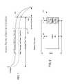
- FIG. 1shows two typical voltage curves of a lithium-ion rechargeable battery under different operating conditions.
- the solid lineis a voltage curve under an optimal operating condition, i.e., lower discharge rate, higher operating temperature, and a newer cell.
- the dashed lineis a voltage curve under a worse operating condition, i.e., higher discharge rate, lower operating temperature, and an older cell.
- the voltageis relatively constant during the useful life of a battery's single discharge cycle; it drops off rather suddenly at the end of the cycle.
- a battery systemmay either be cut off too soon or fail unexpectedly. The latter may result in inconvenient or serious consequences. For example, in a computer device, an unexpected battery failure may result in loss of important data; in an electric vehicle, a motorist may be stranded; and in a medical device, it could be a matter of life and death.
- FIG. 1shows typical voltage curves of a lithium-ion rechargeable battery under different operating conditions
- FIG. 2shows one embodiment of a split rechargeable-battery system that includes two rechargeable battery subsystems
- FIG. 3illustrates an embodiment of a split rechargeable-battery system in greater detail, showing an operating battery system and controlled-shutdown battery system as well as a “fuel” gauge intended to show the remaining capacity of the overall battery system at a given time;
- FIG. 4is a flow diagram of operations carried out by a battery control unit for the operational battery system in one embodiment
- FIG. 5illustrates an alternative embodiment of a split rechargeable-battery system in which the split battery concept of FIG. 2 is extended further by splitting at least the operational battery system into multiple battery subsystems and alternating or sequencing their use in respective portions of an operating cycle and/or switching in one or more additional subsystems when more power is required.
- a rechargeable battery systemis split into two or more battery subsystems which may be applied one after another to deliver power to a load.
- an operating battery subsystemis applied to deliver power until it reaches a predetermined or dynamically determined discharge point, and then a controlled-shutdown battery system is applied to deliver reserve power.
- Applying the two battery subsystems in successiontakes much of the guesswork out of predicting the available operating time of the overall battery system by providing a definite end of life milestone near the end of the battery systems' true single charge operating cycle while at the same time making the overall end of life of the battery system much more predictable.
- improved calibration statisticse.g., for determining battery wear
- the split battery systemcreates an environment in which battery cells are charged and discharged to more constant and deterministic voltages.
- the rechargeable battery systemis split into multiple battery systems that may be applied in succession to power the load (cascading from one subsystem to the next until all subsystems have been depleted) or ganged to deliver a level of power that exceeds the capability of one battery subsystem alone.
- the embodiments hereinenable more accurate prediction of the end of battery system life in a single charge cycle by splitting the battery into two or more separate battery systems which can be switched in and out as needed.
- the first (operating) battery systemis the main power delivery battery and is therefore much larger than the second battery system (i.e., the controlled-shutdown battery subsystem).
- the second battery systemprovides a backup to the first battery system and only takes over at the point the first battery system fails or crosses a predefined low voltage threshold. A good analogy is given in the diagram of FIG.
- the first battery systemtakes the device to the Maximum Run Time vertical line 105 and the second battery system switches in only when the first system reaches that point to save the operating state to Disk/Flash, or other action appropriate to the battery system application.
- the specific action to be taken upon reaching the maximum run timemay be made more general by thinking of the left hand side as an operating state and the right hand side as a controlled-shutdown state. System designers may gauge the battery size of the operating-state battery subsystem (system 1 ) versus the controlled-shutdown battery subsystem (system 2 ) based on the needs of the worst case controlled-shutdown period.
- thismay be, for example, the point where the vehicle could switch over to the system 2 battery to provide sufficient reserve power to get the vehicle safely back to a recharging station without stranding the vehicle operator.
- the ability to apply battery subsystems either individually (and thus successively) or ganged in response to increased power demandprovides the benefits of both configurations as conditions require.
- FIG. 2shows one embodiment of a split rechargeable-battery system 150 that includes two rechargeable battery subsystems: an operating battery system 151 (OBS), and a controlled-shutdown battery system 153 (CSBS).
- OBSis the main operating subsystem and is therefore much larger than the CSBS.
- the OBSprovides 90% of the total system battery capacity, and the CSBS provides a 10% reserve.
- the OBSWhen the OBS reaches end of life in a discharge cycle, the OBS is switchably decoupled from the “Main” output terminals via switch(es) 152 (and thus decoupled from the load), and the CSBS is switchably coupled to the output terminals via switch(es) 154 in an operation referred to herein as a “switch-over.”
- a switch-over pointis indicated, for example, by vertical line 105 in FIG. 1 , which marks, for example, the “maximum run time” for the OBS.
- the CSBSenables the host system (i.e., electric vehicle, industrial load, battery-powered medical device, computer, etc.) to safely perform a controlled-shutdown after the switch-over occurs.
- the host systemi.e., electric vehicle, industrial load, battery-powered medical device, computer, etc.
- datacan be saved during the controlled-shutdown period; in an electric vehicle, a motorist can drive to a nearby recharging station, or a medical device operator may be alerted to the low power condition with confidence that a dependable level of power remains to conclude any critical activities.
- the relative sizes of OBS and CSBSmay be determined by the needs of the worst case controlled-shutdown period and/or by maximum power requirements under normal operating conditions when the OBS is driving the load. Also, the OBS and CSBS may be included within a single battery pack or within separate battery packs, and may include battery cells having the same or different battery chemistries and/or form-factors.
- a pre-defined voltage thresholdmay be designed or programmed within a battery monitoring system and used as a pass/fail threshold for the voltages of individual cells or groups of cells within the split battery system.
- the monitoring systemmay trigger a switch-over.
- a dynamically determined switch-over thresholdmay be applied.
- a voltage offset from a run-time determined voltagesuch as the voltage of the battery system at full charge
- the voltage offsetmay be fixed relative to the run-time determination, or may be compensated by various factors including without limitation, loading (or discharge rate), temperature, age of battery (e.g., as measured by a continuously running clock, or the number of discharge cycles detected, revolutions of a drive shaft or other mechanical load, etc.).
- the switch-over thresholditself may be a static voltage and/or voltage slew-rate (i.e., rate of voltage change) or more generally, any useful measure of the discharge level of a battery cell or group of battery cells.
- any of the foregoing techniques for triggering switch-overmay be run-time or programmatically selected according to operating conditions, battery age and/or application needs, including transitioning from one switch-over trigger to another upon detecting a change in operating conditions or loading.
- capacity calibrationmay be performed on regular event intervals or time intervals, for example, after a predetermined number of discharge cycles or elapsed time.
- capacity calibrationinvolves discharging the battery from a fully charged state to a relatively complete discharge state in which the output voltage drops significantly below the normal operating voltage (e.g., a predetermined voltage beyond the maximum run-time line 105 of FIG. 1 ).
- the battery systemwill eventually be unable to drive the load at some point during the capacity calibration, such calibration operations are generally performed in conventional battery systems when the battery is not in active duty.
- such calibrationessentially amounts to running out of fuel; an operation that would generally be undertaken at a service station to avoid stranding the vehicle operator.
- This limitationis overcome by the split battery system proposed herein. More specifically, the CSBS remains available even after the OBS is discharged, thereby enabling the OBS to occasionally be completely discharged (or at least discharged to a deterministic level) and thus calibrated during normal operating conditions.
- the calibration eventmay be signaled to the vehicle operator or rendered entirely without operator knowledge.
- FIG. 3illustrates an embodiment of a split rechargeable-battery system 175 in greater detail, showing an operating battery system 177 and controlled-shutdown battery system 179 as well as a “fuel” gauge 195 intended to show the remaining capacity of the overall battery system (the OBS and CSBS, collectively) at a given time.
- the fuel gaugemay be omitted if unnecessary in a given application. Also, separate gauges or other indicators may be presented for each battery subsystem.
- the OBS 177 and CSBS 179are shown as having an identical implementation, including a number (N) of blocks of recharge-able battery cells 185 (e.g., each block containing some number of parallel-coupled re-chargeable battery cells, like lithium-ion cells according to 18650 or other form factor), load switches 188 a / 188 b and battery control unit 186 .
- the OBS or CSBS or bothmay have different configurations, numbers of blocks of cells, or numbers of cells per block.
- a single battery control unit(with or without redundancy) may be provided to monitor all the battery subsystems.
- the cell-blocks 185are coupled in series between the load switches (e.g., semiconductor or relay-throw elements, or any other elements that enables signal controlled transition between open and closed connection at the switch poles), which are in turn switched to an open or closed (discontinuous or continuous) state according to an output from the control unit.
- the load switchese.g., semiconductor or relay-throw elements, or any other elements that enables signal controlled transition between open and closed connection at the switch poles
- the load switchese.g., semiconductor or relay-throw elements, or any other elements that enables signal controlled transition between open and closed connection at the switch poles
- the OBS cell-blocksare enabled to deliver power to a load via output terminals, V+, V ⁇ (which correspond to the “main” terminals of FIG. 1 ), and when the switches are open, the OBS is shut off or disabled from driving the load.
- the OBSmay be switched out (de-coupled from the load) at some point during its discharge cycle, and the CSBS switched in via its own load switches to provide a dependable amount of reserve power.
- control unit 186 within the OBSincludes a microcontroller 193 , analog-to-digital converter 191 , multiplexer (or selector) 189 and signal-conditioning elements 187 . Any or all of these components may be integrated onto a single integrated-circuit device (e.g., an application-specific integrated circuit) or implemented as discrete elements within the control unit.
- the microcontrollerexecutes a pre-loaded program (e.g., burned into non-volatile memory within the microcontroller itself or another storage within or separate from the control unit) to read, in round-robin fashion, the individual voltage potential of each block of cells, determine based on those readings (or measurements) whether a switch-over threshold has been reached and if so, effect a switch-over to the CSBS.
- the micro-controlleroutputs a selection signal 190 that sequences the multiplexer 189 through selection of each of the pre-conditioned cell-block voltages in turn, triggering a sequence of analog-to-digital operations within A/D converter 191 (via enable signal 192 ) to obtain a digitized representation of each cell-block voltage.
- pre-conditioningis entirely optional, but that conditioning elements 187 may include, for example, amplification or filtering of any sort.
- the micro-controller 193determines that a switch-over threshold has been reached, the micro-controller opens the OBS load switches, and notifies the control unit for the CSBS of the switch-over via system interface 196 .
- the CSBS control unitresponds to the switch over by closing its load switches to enable the CSBS battery cells to drive the load.
- the CSBS control unitadditionally begins (or continues) monitoring the CSBS voltages and reporting those voltages to the OBS control unit (e.g., via system interface 196 ) which in turn, drives the fuel gauge 195 .
- the OBS control unitmay additionally signal the operator that a switch-over has occurred (e.g., by displaying an indicator on the fuel gauge 195 indicating that the system is under reserve power or down to a remaining percentage capacity (e.g., 10% in this example).
- a switch-overe.g., by displaying an indicator on the fuel gauge 195 indicating that the system is under reserve power or down to a remaining percentage capacity (e.g., 10% in this example).
- the battery control units within the OBS and CSBSmay additionally monitor load current (or other indicator of battery discharge) to enable a determination of the total amount of energy delivered to the load and thus to approximate the consumption of charge on the fuel gauge. Such discharge measurements may also be used in a capacity calibration operation as discussed below.
- FIG. 4is a flow diagram of operations carried out by the OBS control unit in one embodiment.
- the OBS control unitinitially samples the load current and all OBS block voltages at 221 , then updates the accumulated power consumption (referred to herein as amp-hour (AH) consumption) at 223 and updates the fuel gauge at 225 by subtracting the AH consumption from a previously calibrated, total capacity value. So long as none of the cell-block voltages are undervoltage (determined in decision block 227 ), the OBS control unit continues to execute the monitoring and update operations shown at 221 , 223 and 225 . In the embodiment shown, if any of the cell-block voltages is determined to be undervoltage, the control unit next determines whether a capacity calibration is needed at decision block 229 .
- AHamp-hour
- undervoltage thresholdsmay be used, and undervoltage may be determined in whole or part based on a group of blocks or even all the blocks collectively rather than based on the voltage for an individual block.
- the OBS control unitmay, for example, track the number of times an under-voltage condition has been reached within the OBS (i.e., number of discharge cycles) and/or elapsed time since last capacity calibration was carried out, determining that a calibration is needed if either of those metrics exceed a predefined or programmed threshold.
- Each pass through the monitoring-and-update loop(i.e., as shown at 221 , 223 , 225 , 227 ) may be triggered on regular intervals (e.g., by expiration of a counter within the microcontroller 193 or operation of other timing circuitry), to enable incremental power consumption to be determined.
- the OBSdrops the undervoltage threshold to a deep discharge level and then continues the monitoring-and-update loop effected by operations 221 , 223 , 225 , 227 .
- the OBS control uniteffectively retains the OBS as the system power source until the deep discharge threshold is reached and, at that point, applies the total amp-hours consumed during the overall discharge cycle to update the capacity of the OBS and thus the overall battery system.
- the OBS control unitde-couples the OBS from the battery-system output terminals at 231 , signals the switch-over to CSBS at 233 (i.e., notifying the CSBS controller and thus enabling the CSBS to be coupled to the output terminals to drive the load), and then begins receiving cell-block voltage and load current measurements from the CSBS control unit and updating the fuel gauge (and total amp-hour consumption) accordingly at 235 .
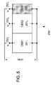
- FIG. 5illustrates an alternative embodiment of a split rechargeable-battery system 250 in which the split battery concept of FIG. 2 is extended further by splitting the operational battery system (OBS) into N battery subsystems and alternating their use upon operating cycles and/or switching a subsystem in when more power is required (e.g., using a HV diode to equalize voltage).
- the first N ⁇ 1 equal-sized battery systemsmay be designated as Operating Battery System 1 (OBS 1 ) thru Operating Battery System N ⁇ 1 (OBSN ⁇ 1) while the remaining smaller Nth end-of-operating cycle battery subsystem is designated as the Controlled-shutdown Battery System (CSBS).
- OBSOperating Battery System 1
- CSBSControlled-shutdown Battery System
- RSBSRechargable Split Battery System
- each of the rechargeable battery subsystemsmay be applied in succession to power a load, switching over from OBS 1 to OBS 2 and then to CSBS as each subsystem reaches a depletion point (i.e., switch-over point).
- This approachmay be extended, splitting (or dividing or partitioning) the battery system into any practical number of battery subsystems, each of which may be applied in succession as a previous subsystem reaches a switch-over point.
- the CSBSmay be undifferentiated from the operational battery subsystems, except to act as the last of the battery subsystems to be applied and thus the final reserve in the overall operating capacity.
- split battery system of FIG. 5One potential disadvantage of the split battery system of FIG. 5 is that the smaller operating size of the individual battery subsystems results in faster discharge of each subsystem. As can be see from the above Voltage/Capacity diagram of FIG. 1 , this increased discharge rate may skew the ability to estimate remaining electrical charge. What is not shown in FIG. 1 is that frequent high discharge also reduces the life of the battery system. Thus, a significant advantage of the split battery concept is that each battery system may be charged more often from a known discharge state than would normally be the case where the battery was operated only nominally a majority of the time.
- the battery systemmay be designed to operate on any combination of the three battery systems to allow the user or the battery system controller the ability to intelligently provide power as needed to the device without needless high discharge while still allowing for battery charge calibration. That is, all the battery subsystems may be ganged to effect a unified battery system, the battery subsystems may be partially ganged to effect the split battery subsystem of FIG. 2 , or the battery subsystems may be applied individually, all in response to dynamically determined power demands.
- a battery control unit similar to the battery control units described in reference to FIG. 3is provided with each battery subsystem (OBS 1 -OBSN and CSBS) and enables a coordinated switch-over from one subsystem to the next.
- a supervising one of the control unitse.g., the control unit for OBS 1
- high-voltage diodesmay be use to equalize the voltages as two battery subsystems initially switched in parallel to the load terminals. Thereafter, as power demand falls off, the supervising control unit may instruct the control units of the ganged battery subsystems to disengage accordingly.
- the control circuitrymay engage only one of the battery subsystems when the vehicle is not accelerating and traveling at a moderate or slow speed (i.e., during relatively low power demand), but may engage one or more additional battery subsystems when the operator demands acceleration (e.g., presses the “gas” pedal) or the vehicle is operating at high speed.
- a split battery system with multiple battery subsystemsprovides another advantage. Because frequent deep discharge tends to reduce the overall life a rechargeable battery (i.e., deep discharge tends to speed the cycle-to-cycle decline in total capacity), it is often desirable to charge a battery from a predefined discharge state, such as the state indicated by the vertical dashed line 107 in FIG. 1 , well before it reaches the maximum run time.
- a predefined discharge statesuch as the state indicated by the vertical dashed line 107 in FIG. 1
- an overall battery control unitmay alternate use of different battery subsystems. For example, the control unit may engage each battery subsystem sequentially, switching to the next battery subsystem when the currently-engaged subsystem has reached the predefined discharge state.
Landscapes
- Engineering & Computer Science (AREA)
- Power Engineering (AREA)
- Manufacturing & Machinery (AREA)
- Chemical & Material Sciences (AREA)
- Chemical Kinetics & Catalysis (AREA)
- Electrochemistry (AREA)
- General Chemical & Material Sciences (AREA)
- Secondary Cells (AREA)
- Charge And Discharge Circuits For Batteries Or The Like (AREA)
- Stand-By Power Supply Arrangements (AREA)
Abstract
Description
- much more predictable fuel gauge for rechargeable batteries, especially at the end of life of the battery system where it is most critical;
- enable estimation of true battery operating life and calibration of battery charging; and
- ensure a safe predictable controlled-shutdown period prior to complete battery system shutdown.
Claims (14)
Priority Applications (3)
| Application Number | Priority Date | Filing Date | Title |
|---|---|---|---|
| US12/372,714US8143855B2 (en) | 2008-02-15 | 2009-02-17 | Rechargeable split battery system |
| CN200980113518.3ACN102007664B (en) | 2009-02-17 | 2009-04-11 | Rechargeable split battery system |
| PCT/US2009/040290WO2009103091A2 (en) | 2008-02-15 | 2009-04-11 | A rechargeable split battery system |
Applications Claiming Priority (2)
| Application Number | Priority Date | Filing Date | Title |
|---|---|---|---|
| US2929608P | 2008-02-15 | 2008-02-15 | |
| US12/372,714US8143855B2 (en) | 2008-02-15 | 2009-02-17 | Rechargeable split battery system |
Publications (2)
| Publication Number | Publication Date |
|---|---|
| US20090218989A1 US20090218989A1 (en) | 2009-09-03 |
| US8143855B2true US8143855B2 (en) | 2012-03-27 |
Family
ID=40957545
Family Applications (1)
| Application Number | Title | Priority Date | Filing Date |
|---|---|---|---|
| US12/372,714Active2030-01-20US8143855B2 (en) | 2008-02-15 | 2009-02-17 | Rechargeable split battery system |
Country Status (2)
| Country | Link |
|---|---|
| US (1) | US8143855B2 (en) |
| WO (1) | WO2009103091A2 (en) |
Cited By (9)
| Publication number | Priority date | Publication date | Assignee | Title |
|---|---|---|---|---|
| US20110111268A1 (en)* | 2009-11-11 | 2011-05-12 | Sam Weng | Interlock Mechanism for a Multiple Battery Pack |
| US20110173469A1 (en)* | 2008-11-21 | 2011-07-14 | Toyota Jidosha Kabushiki Kaisha | Control apparatus and control method for vehicle |
| US20120056587A1 (en)* | 2009-05-08 | 2012-03-08 | Takuma Iida | Power supply device and battery pack |
| US20130162030A1 (en)* | 2011-12-21 | 2013-06-27 | Volvo Car Corporation | Power supply system for powering an electric load of a vehicle |
| US8643335B2 (en)* | 2010-12-21 | 2014-02-04 | Honda Motor Co., Ltd. | Power supply apparatus |
| US20140207318A1 (en)* | 2013-01-11 | 2014-07-24 | Johnson Controls Technology Company | Energy Storage Control System and Method |
| US9077186B2 (en) | 2011-04-27 | 2015-07-07 | Honda Motor Co., Ltd. | Power supply device |
| US20180037132A1 (en)* | 2016-08-05 | 2018-02-08 | Fu-Chieh Chen | Secondary lithium battery for vehicle use |
| EP4236022A4 (en)* | 2021-08-02 | 2024-10-02 | LG Energy Solution, Ltd. | Battery control device, operation method thereof, and battery control system |
Families Citing this family (20)
| Publication number | Priority date | Publication date | Assignee | Title |
|---|---|---|---|---|
| US20100131134A1 (en)* | 2008-11-24 | 2010-05-27 | Wallace David L | Self Sustaining Electric Engine Enhancement (SSEEE) |
| SG172494A1 (en)* | 2009-12-16 | 2011-07-28 | Green 5 Holding Pte Ltd | Digital electronic second identity for vechicle |
| JP5012962B2 (en)* | 2010-06-14 | 2012-08-29 | トヨタ自動車株式会社 | Vehicle power control device |
| WO2012021137A1 (en)* | 2010-08-13 | 2012-02-16 | Hewlett-Packard Development Company L.P. | Transmitting location information from a computing device |
| JP5527895B2 (en)* | 2010-11-18 | 2014-06-25 | パナソニック株式会社 | Secondary battery control device and control method |
| SE537392C2 (en) | 2011-12-14 | 2015-04-21 | Scania Cv Ab | Method and system for battery charging of a vehicle |
| DE102012205260A1 (en)* | 2012-03-30 | 2013-10-02 | Robert Bosch Gmbh | Electrical device and method for operating an electrical device |
| JP5768001B2 (en)* | 2012-04-23 | 2015-08-26 | 株式会社日立製作所 | Battery system maintenance management system and method |
| US9211802B2 (en)* | 2012-12-14 | 2015-12-15 | GM Global Technology Operations LLC | Systems and methods for detecting a weak subdivision in a battery system |
| US9190853B2 (en)* | 2013-07-25 | 2015-11-17 | GM Global Technology Operations LLC | Methods and systems for adjusting battery voltage limits |
| US9789319B2 (en) | 2013-11-21 | 2017-10-17 | Medtronic, Inc. | Systems and methods for leadless cardiac resynchronization therapy |
| US20210391622A1 (en)* | 2014-04-17 | 2021-12-16 | Michael L Froelich | Battery and Motor Systems for Electric-Powered Vehicles |
| JP6258373B2 (en)* | 2016-02-16 | 2018-01-10 | 本田技研工業株式会社 | Power supply system |
| US10677852B1 (en) | 2017-11-07 | 2020-06-09 | Amazon Technologies, Inc. | Determining battery capacity |
| CN107026478B (en)* | 2017-06-09 | 2023-09-05 | 上海历挚机电设备有限公司 | Grid-connected control system and control method for photovoltaic power station |
| US10594158B2 (en)* | 2017-07-26 | 2020-03-17 | Quanta Computer Inc. | ORing FET control method for battery backup system |
| US10770911B1 (en)* | 2017-11-13 | 2020-09-08 | Amazon Technologies, Inc. | Calibrating battery fuel gages |
| KR102390394B1 (en)* | 2018-05-15 | 2022-04-22 | 주식회사 엘지에너지솔루션 | Apparatus and method for controlling main battery and sub battery |
| DE102019113664A1 (en)* | 2019-05-22 | 2020-11-26 | Hoppecke Batterien Gmbh & Co. Kg | Battery arrangement with at least one power battery for delivering electrical energy |
| DE102021110774A1 (en)* | 2021-04-27 | 2022-10-27 | Rolls-Royce Deutschland Ltd & Co Kg | Electric propulsion system |
Citations (25)
| Publication number | Priority date | Publication date | Assignee | Title |
|---|---|---|---|---|
| US4017779A (en)* | 1976-03-22 | 1977-04-12 | Motorola, Inc. | Battery isolator |
| US4181842A (en) | 1976-09-13 | 1980-01-01 | Honeywell Inc. | D.C. monitoring circuit |
| US4698578A (en) | 1986-05-27 | 1987-10-06 | Gates Energy Products | Circuit for supplying energy from a battery to an energy-using device |
| US4709202A (en) | 1982-06-07 | 1987-11-24 | Norand Corporation | Battery powered system |
| US4812672A (en) | 1987-10-01 | 1989-03-14 | Northern Telecom Limited | Selective connection of power supplies |
| US4814631A (en) | 1980-08-06 | 1989-03-21 | Jackson Terry R | Electrical power supply having a variable output |
| US4818928A (en)* | 1987-10-01 | 1989-04-04 | Duracell Inc. | Battery pack |
| US5300874A (en) | 1989-09-29 | 1994-04-05 | Kabushiki Kaisha Toshiba | Intelligent power supply system for a portable computer |
| US5461264A (en) | 1991-10-29 | 1995-10-24 | Yang; Tai-Her | Multi-voltage control circuit of battery or multiple independent DC power |
| US5483433A (en) | 1992-08-28 | 1996-01-09 | Yang; Tai-Her | Voltage control circuit for a multiple stage DC power supply, and applications thereof |
| JPH08251714A (en) | 1995-03-10 | 1996-09-27 | Mitsubishi Motors Corp | Electric vehicle power supply |
| US5717310A (en) | 1995-12-08 | 1998-02-10 | Honda Giken Kogyo Kabushiki Kaisha | Power supply control device for electric vehicle |
| US5796224A (en) | 1995-04-28 | 1998-08-18 | Honda Giken Kogyo Kabushiki Kaisha | Control system for electric vehicle |
| US5814972A (en) | 1993-05-13 | 1998-09-29 | Canon Kabushiki Kaisha | Electronic apparatus having multiple loads, driven by plural batteries |
| US5883496A (en) | 1996-05-08 | 1999-03-16 | Toyota Jidosha Kabushiki Kaisha | Electric vehicle power supply |
| US6084382A (en)* | 1998-04-27 | 2000-07-04 | Hewlett-Packard Company | Battery systems and methods of supplying electrical energy |
| US6268711B1 (en)* | 1999-05-05 | 2001-07-31 | Texas Instruments Incorporated | Battery manager |
| JP2003226207A (en) | 2002-02-06 | 2003-08-12 | Yazaki Corp | Power supply system for vehicles |
| US6674180B2 (en) | 2001-10-12 | 2004-01-06 | Ford Global Technologies, Llc | Power supply for a hybrid electric vehicle |
| US6828758B2 (en)* | 2002-02-20 | 2004-12-07 | Toyota Jidosha Kabushiki Kaisha | Charge/discharge control method for battery pack and charge/discharge control apparatus for battery pack |
| US6919707B2 (en)* | 2002-01-10 | 2005-07-19 | Panasonic Ev Energy Co., Ltd. | Battery power source device, method for controlling the same, and method for providing address |
| US20050194931A1 (en)* | 2004-03-05 | 2005-09-08 | Denso Corporation | Circuit system for a battery electronic control unit |
| US20060006840A1 (en)* | 2004-07-06 | 2006-01-12 | Kimihiko Furukawa | Power supply apparatus for vehicle |
| US7199489B2 (en) | 1994-03-03 | 2007-04-03 | American Power Conversion Corporation | Battery communication system |
| US20080048608A1 (en)* | 2006-08-22 | 2008-02-28 | Samsung Sdi Co., Ltd. | Hybrid battery pack and methods of charging and discharging the same |
Family Cites Families (3)
| Publication number | Priority date | Publication date | Assignee | Title |
|---|---|---|---|---|
| US5371682A (en)* | 1993-02-04 | 1994-12-06 | At&T Corp. | Method and apparatus for predicting battery reserve time to a specified end-voltage |
| KR970007604B1 (en)* | 1994-04-27 | 1997-05-13 | 삼성전자 주식회사 | Grcuit of exchangin battery automatically |
| JP3976268B2 (en)* | 2003-11-28 | 2007-09-12 | インターナショナル・ビジネス・マシーンズ・コーポレーション | Battery pack, electrical device, computer apparatus, battery control method, power supply method, and program |
- 2009
- 2009-02-17USUS12/372,714patent/US8143855B2/enactiveActive
- 2009-04-11WOPCT/US2009/040290patent/WO2009103091A2/enactiveApplication Filing
Patent Citations (26)
| Publication number | Priority date | Publication date | Assignee | Title |
|---|---|---|---|---|
| US4017779A (en)* | 1976-03-22 | 1977-04-12 | Motorola, Inc. | Battery isolator |
| US4181842A (en) | 1976-09-13 | 1980-01-01 | Honeywell Inc. | D.C. monitoring circuit |
| US4814631A (en) | 1980-08-06 | 1989-03-21 | Jackson Terry R | Electrical power supply having a variable output |
| US4709202A (en) | 1982-06-07 | 1987-11-24 | Norand Corporation | Battery powered system |
| US4698578A (en) | 1986-05-27 | 1987-10-06 | Gates Energy Products | Circuit for supplying energy from a battery to an energy-using device |
| US4818928A (en)* | 1987-10-01 | 1989-04-04 | Duracell Inc. | Battery pack |
| US4812672A (en) | 1987-10-01 | 1989-03-14 | Northern Telecom Limited | Selective connection of power supplies |
| US5300874A (en) | 1989-09-29 | 1994-04-05 | Kabushiki Kaisha Toshiba | Intelligent power supply system for a portable computer |
| US5461264A (en) | 1991-10-29 | 1995-10-24 | Yang; Tai-Her | Multi-voltage control circuit of battery or multiple independent DC power |
| US5483433A (en) | 1992-08-28 | 1996-01-09 | Yang; Tai-Her | Voltage control circuit for a multiple stage DC power supply, and applications thereof |
| US5814972A (en) | 1993-05-13 | 1998-09-29 | Canon Kabushiki Kaisha | Electronic apparatus having multiple loads, driven by plural batteries |
| US7199489B2 (en) | 1994-03-03 | 2007-04-03 | American Power Conversion Corporation | Battery communication system |
| JPH08251714A (en) | 1995-03-10 | 1996-09-27 | Mitsubishi Motors Corp | Electric vehicle power supply |
| US5796224A (en) | 1995-04-28 | 1998-08-18 | Honda Giken Kogyo Kabushiki Kaisha | Control system for electric vehicle |
| US5717310A (en) | 1995-12-08 | 1998-02-10 | Honda Giken Kogyo Kabushiki Kaisha | Power supply control device for electric vehicle |
| US5883496A (en) | 1996-05-08 | 1999-03-16 | Toyota Jidosha Kabushiki Kaisha | Electric vehicle power supply |
| US6084382A (en)* | 1998-04-27 | 2000-07-04 | Hewlett-Packard Company | Battery systems and methods of supplying electrical energy |
| US6268711B1 (en)* | 1999-05-05 | 2001-07-31 | Texas Instruments Incorporated | Battery manager |
| US6674180B2 (en) | 2001-10-12 | 2004-01-06 | Ford Global Technologies, Llc | Power supply for a hybrid electric vehicle |
| US6930404B1 (en) | 2001-10-12 | 2005-08-16 | Ford Global Technologies, Llc | Power supply for an automotive vehicle |
| US6919707B2 (en)* | 2002-01-10 | 2005-07-19 | Panasonic Ev Energy Co., Ltd. | Battery power source device, method for controlling the same, and method for providing address |
| JP2003226207A (en) | 2002-02-06 | 2003-08-12 | Yazaki Corp | Power supply system for vehicles |
| US6828758B2 (en)* | 2002-02-20 | 2004-12-07 | Toyota Jidosha Kabushiki Kaisha | Charge/discharge control method for battery pack and charge/discharge control apparatus for battery pack |
| US20050194931A1 (en)* | 2004-03-05 | 2005-09-08 | Denso Corporation | Circuit system for a battery electronic control unit |
| US20060006840A1 (en)* | 2004-07-06 | 2006-01-12 | Kimihiko Furukawa | Power supply apparatus for vehicle |
| US20080048608A1 (en)* | 2006-08-22 | 2008-02-28 | Samsung Sdi Co., Ltd. | Hybrid battery pack and methods of charging and discharging the same |
Non-Patent Citations (1)
| Title |
|---|
| International Search Report and Written Opinion of the International Searching Authority regarding PCT Application PCT/US2009/040290, Oct. 13, 2009, 11 pages. |
Cited By (14)
| Publication number | Priority date | Publication date | Assignee | Title |
|---|---|---|---|---|
| US20110173469A1 (en)* | 2008-11-21 | 2011-07-14 | Toyota Jidosha Kabushiki Kaisha | Control apparatus and control method for vehicle |
| US8683244B2 (en)* | 2008-11-21 | 2014-03-25 | Toyota Jidosha Kabushiki Kaisha | Control apparatus and control method for vehicle |
| US20120056587A1 (en)* | 2009-05-08 | 2012-03-08 | Takuma Iida | Power supply device and battery pack |
| US20110111268A1 (en)* | 2009-11-11 | 2011-05-12 | Sam Weng | Interlock Mechanism for a Multiple Battery Pack |
| US8866441B2 (en)* | 2009-11-11 | 2014-10-21 | Atieva, Inc. | Interlock mechanism for a multiple battery pack |
| US8643335B2 (en)* | 2010-12-21 | 2014-02-04 | Honda Motor Co., Ltd. | Power supply apparatus |
| US9077186B2 (en) | 2011-04-27 | 2015-07-07 | Honda Motor Co., Ltd. | Power supply device |
| US9272625B2 (en)* | 2011-12-21 | 2016-03-01 | Volvo Car Corporation | Power supply system for powering an electric load of a vehicle |
| US20130162030A1 (en)* | 2011-12-21 | 2013-06-27 | Volvo Car Corporation | Power supply system for powering an electric load of a vehicle |
| US20140207318A1 (en)* | 2013-01-11 | 2014-07-24 | Johnson Controls Technology Company | Energy Storage Control System and Method |
| US9085238B2 (en)* | 2013-01-11 | 2015-07-21 | Johnson Controls Technology Company | Energy storage control system and method |
| US9469212B2 (en) | 2013-01-11 | 2016-10-18 | Johnson Controls Technology Company | Energy storage control system and method |
| US20180037132A1 (en)* | 2016-08-05 | 2018-02-08 | Fu-Chieh Chen | Secondary lithium battery for vehicle use |
| EP4236022A4 (en)* | 2021-08-02 | 2024-10-02 | LG Energy Solution, Ltd. | Battery control device, operation method thereof, and battery control system |
Also Published As
| Publication number | Publication date |
|---|---|
| WO2009103091A3 (en) | 2009-12-03 |
| US20090218989A1 (en) | 2009-09-03 |
| WO2009103091A2 (en) | 2009-08-20 |
Similar Documents
| Publication | Publication Date | Title |
|---|---|---|
| US8143855B2 (en) | Rechargeable split battery system | |
| US11067636B2 (en) | Battery aging state calculation method and system | |
| JP4009537B2 (en) | Charge control device, battery management system, battery pack, and secondary battery deterioration determination method using the same | |
| US9800066B2 (en) | Electricity distribution device, and controlling method for battery pack | |
| US8669741B2 (en) | Battery management system and driving method thereof | |
| KR101547005B1 (en) | Apparatus and method for estimating state of charging of battery | |
| US8508192B2 (en) | Battery pack capable of calculating relative remaining capacity | |
| JP5567741B2 (en) | Method for monitoring battery charging process, battery system, and vehicle | |
| US9634498B2 (en) | Electrical storage system and equalizing method | |
| EP2894760B1 (en) | Method for refresh charging of a lead battery, and corresponding charging device | |
| EP2161812A1 (en) | Power supply system, and power supply control method and power supply control program employed in power supply system | |
| US9680320B2 (en) | Battery control apparatus | |
| WO2014204649A1 (en) | Battery management system | |
| KR102014719B1 (en) | Battery life management device | |
| WO2012132160A1 (en) | Device for measuring degradation, rechargeable battery pack, method for measuring degradation, and program | |
| US20130082658A1 (en) | Battery pack for electric power tool | |
| JP2007309839A (en) | Battery pack state measuring device, battery pack deterioration judgment method and battery pack deterioration judgment program | |
| US20200136399A1 (en) | Battery control device | |
| JP2009064682A (en) | Battery deterioration judging device, and lithium ion battery pack equipped with the same | |
| JP2007311255A (en) | Battery pack state measuring device, battery pack deterioration judgment method and battery pack deterioration judgment program | |
| US20220097566A1 (en) | Cell Balancing Device | |
| CN109795368A (en) | Power control system and power control method | |
| EP1918728B1 (en) | Lithium-ion battery diagnostic and prognostic techniques | |
| EP4549970A1 (en) | Method for diagnosing degree of deterioration of battery cells, and battery system using same | |
| US20110031975A1 (en) | Battery-Driven Power Tool and Battery Pack Therefor |
Legal Events
| Date | Code | Title | Description |
|---|---|---|---|
| AS | Assignment | Owner name:ATIEVA, INC., CALIFORNIA Free format text:ASSIGNMENT OF ASSIGNORS INTEREST;ASSIGNOR:DAVIS, KERRY;REEL/FRAME:022685/0322 Effective date:20090507 | |
| STCF | Information on status: patent grant | Free format text:PATENTED CASE | |
| FPAY | Fee payment | Year of fee payment:4 | |
| AS | Assignment | Owner name:MORGAN STANLEY SENIOR FUNDING, INC., MARYLAND Free format text:ASSIGNMENT AND ASSUMPTION OF SECURITY INTEREST IN PATENTS;ASSIGNOR:CITIBANK, N.A.;REEL/FRAME:037518/0292 Effective date:20151207 | |
| AS | Assignment | Owner name:MORGAN STANLEY SENIOR FUNDING, INC., MARYLAND Free format text:CORRECTIVE ASSIGNMENT TO CORRECT THE REMOVE PATENTS 8108266 AND 8062324 AND REPLACE THEM WITH 6108266 AND 8060324 PREVIOUSLY RECORDED ON REEL 037518 FRAME 0292. ASSIGNOR(S) HEREBY CONFIRMS THE ASSIGNMENT AND ASSUMPTION OF SECURITY INTEREST IN PATENTS;ASSIGNOR:CITIBANK, N.A.;REEL/FRAME:041703/0536 Effective date:20151207 | |
| AS | Assignment | Owner name:TRINITY CAPITAL FUND III, L. P., ARIZONA Free format text:INTELLECTUAL PROPERTY SECURITY AGREEMENT;ASSIGNOR:ATIEVA, INC;REEL/FRAME:042125/0897 Effective date:20170331 | |
| AS | Assignment | Owner name:YINLONG ELECTRIC VEHICLE (HK) GROUP LIMITED, HONG KONG Free format text:SECURITY INTEREST;ASSIGNORS:ATIEVA, INC.;ATIEVA USA, INC;REEL/FRAME:044457/0942 Effective date:20171027 Owner name:YINLONG ELECTRIC VEHICLE (HK) GROUP LIMITED, HONG Free format text:SECURITY INTEREST;ASSIGNORS:ATIEVA, INC.;ATIEVA USA, INC;REEL/FRAME:044457/0942 Effective date:20171027 | |
| AS | Assignment | Owner name:ATIEVA INC., CAYMAN ISLANDS Free format text:ASSIGNMENT OF ASSIGNORS INTEREST;ASSIGNOR:ATIEVA USA INC.;REEL/FRAME:046696/0236 Effective date:20180808 | |
| AS | Assignment | Owner name:AVB METRICS, LLC, CALIFORNIA Free format text:RELEASE BY SECURED PARTY;ASSIGNOR:TRINITY CAPITAL FUND III, L.P.;REEL/FRAME:047529/0619 Effective date:20180912 Owner name:ATIEVA, INC., CAYMAN ISLANDS Free format text:RELEASE BY SECURED PARTY;ASSIGNOR:TRINITY CAPITAL FUND III, L.P.;REEL/FRAME:047529/0619 Effective date:20180912 Owner name:ATIEVA USA, INC., CALIFORNIA Free format text:RELEASE BY SECURED PARTY;ASSIGNOR:TRINITY CAPITAL FUND III, L.P.;REEL/FRAME:047529/0619 Effective date:20180912 | |
| AS | Assignment | Owner name:ATIEVA USA, INC., CALIFORNIA Free format text:RELEASE BY SECURED PARTY;ASSIGNOR:YINLONG ELECTRIC VEHICLE (HK) GROUP LIMITED;REEL/FRAME:047620/0451 Effective date:20180914 Owner name:ATIEVA, INC., CAYMAN ISLANDS Free format text:RELEASE BY SECURED PARTY;ASSIGNOR:YINLONG ELECTRIC VEHICLE (HK) GROUP LIMITED;REEL/FRAME:047620/0451 Effective date:20180914 Owner name:AVB METRICS, LLC, CALIFORNIA Free format text:RELEASE BY SECURED PARTY;ASSIGNOR:YINLONG ELECTRIC VEHICLE (HK) GROUP LIMITED;REEL/FRAME:047620/0451 Effective date:20180914 | |
| AS | Assignment | Owner name:AYAR THIRD INVESTMENT COMPANY, SAUDI ARABIA Free format text:SECURITY INTEREST;ASSIGNOR:ATIEVA, INC.;REEL/FRAME:047199/0221 Effective date:20180916 | |
| AS | Assignment | Owner name:SHENZHEN XINGUODU TECHNOLOGY CO., LTD., CHINA Free format text:CORRECTIVE ASSIGNMENT TO CORRECT THE TO CORRECT THE APPLICATION NO. FROM 13,883,290 TO 13,833,290 PREVIOUSLY RECORDED ON REEL 041703 FRAME 0536. ASSIGNOR(S) HEREBY CONFIRMS THE THE ASSIGNMENT AND ASSUMPTION OF SECURITYINTEREST IN PATENTS.;ASSIGNOR:MORGAN STANLEY SENIOR FUNDING, INC.;REEL/FRAME:048734/0001 Effective date:20190217 | |
| AS | Assignment | Owner name:ATIEVA, INC., CALIFORNIA Free format text:RELEASE BY SECURED PARTY;ASSIGNOR:AYAR THIRD INVESTMENT COMPANY;REEL/FRAME:048811/0472 Effective date:20190402 | |
| MAFP | Maintenance fee payment | Free format text:PAYMENT OF MAINTENANCE FEE, 8TH YR, SMALL ENTITY (ORIGINAL EVENT CODE: M2552); ENTITY STATUS OF PATENT OWNER: SMALL ENTITY Year of fee payment:8 | |
| FEPP | Fee payment procedure | Free format text:ENTITY STATUS SET TO UNDISCOUNTED (ORIGINAL EVENT CODE: BIG.); ENTITY STATUS OF PATENT OWNER: LARGE ENTITY | |
| MAFP | Maintenance fee payment | Free format text:PAYMENT OF MAINTENANCE FEE, 12TH YEAR, LARGE ENTITY (ORIGINAL EVENT CODE: M1553); ENTITY STATUS OF PATENT OWNER: LARGE ENTITY Year of fee payment:12 |