US8142504B2 - System for fixing a part to a bone element - Google Patents
System for fixing a part to a bone elementDownload PDFInfo
- Publication number
- US8142504B2 US8142504B2US10/504,388US50438804AUS8142504B2US 8142504 B2US8142504 B2US 8142504B2US 50438804 AUS50438804 AUS 50438804AUS 8142504 B2US8142504 B2US 8142504B2
- Authority
- US
- United States
- Prior art keywords
- rod
- hole
- holes
- longitudinal axis
- spiral
- Prior art date
- Legal status (The legal status is an assumption and is not a legal conclusion. Google has not performed a legal analysis and makes no representation as to the accuracy of the status listed.)
- Active, expires
Links
- 210000000988bone and boneAnatomy0.000titleclaimsabstractdescription34
- 230000004927fusionEffects0.000abstract1
- 239000007943implantSubstances0.000description2
- 238000002513implantationMethods0.000description2
- 229910052751metalInorganic materials0.000description2
- 239000002184metalSubstances0.000description2
- RTAQQCXQSZGOHL-UHFFFAOYSA-NTitaniumChemical compound[Ti]RTAQQCXQSZGOHL-UHFFFAOYSA-N0.000description1
- 239000000560biocompatible materialSubstances0.000description1
- 230000015572biosynthetic processEffects0.000description1
- 230000000295complement effectEffects0.000description1
- 238000007596consolidation processMethods0.000description1
- 229910052588hydroxylapatiteInorganic materials0.000description1
- 238000003754machiningMethods0.000description1
- 239000000463materialSubstances0.000description1
- 238000000034methodMethods0.000description1
- 230000035515penetrationEffects0.000description1
- XYJRXVWERLGGKC-UHFFFAOYSA-Dpentacalcium;hydroxide;triphosphateChemical compound[OH-].[Ca+2].[Ca+2].[Ca+2].[Ca+2].[Ca+2].[O-]P([O-])([O-])=O.[O-]P([O-])([O-])=O.[O-]P([O-])([O-])=OXYJRXVWERLGGKC-UHFFFAOYSA-D0.000description1
- 230000001737promoting effectEffects0.000description1
- 239000010936titaniumSubstances0.000description1
- 229910052719titaniumInorganic materials0.000description1
Images

Classifications
- A—HUMAN NECESSITIES
- A61—MEDICAL OR VETERINARY SCIENCE; HYGIENE
- A61F—FILTERS IMPLANTABLE INTO BLOOD VESSELS; PROSTHESES; DEVICES PROVIDING PATENCY TO, OR PREVENTING COLLAPSING OF, TUBULAR STRUCTURES OF THE BODY, e.g. STENTS; ORTHOPAEDIC, NURSING OR CONTRACEPTIVE DEVICES; FOMENTATION; TREATMENT OR PROTECTION OF EYES OR EARS; BANDAGES, DRESSINGS OR ABSORBENT PADS; FIRST-AID KITS
- A61F2/00—Filters implantable into blood vessels; Prostheses, i.e. artificial substitutes or replacements for parts of the body; Appliances for connecting them with the body; Devices providing patency to, or preventing collapsing of, tubular structures of the body, e.g. stents
- A61F2/02—Prostheses implantable into the body
- A61F2/30—Joints
- A61F2/44—Joints for the spine, e.g. vertebrae, spinal discs
- A61F2/4455—Joints for the spine, e.g. vertebrae, spinal discs for the fusion of spinal bodies, e.g. intervertebral fusion of adjacent spinal bodies, e.g. fusion cages
- A61F2/446—Joints for the spine, e.g. vertebrae, spinal discs for the fusion of spinal bodies, e.g. intervertebral fusion of adjacent spinal bodies, e.g. fusion cages having a circular or elliptical cross-section substantially parallel to the axis of the spine, e.g. cylinders or frustocones
- A—HUMAN NECESSITIES
- A61—MEDICAL OR VETERINARY SCIENCE; HYGIENE
- A61F—FILTERS IMPLANTABLE INTO BLOOD VESSELS; PROSTHESES; DEVICES PROVIDING PATENCY TO, OR PREVENTING COLLAPSING OF, TUBULAR STRUCTURES OF THE BODY, e.g. STENTS; ORTHOPAEDIC, NURSING OR CONTRACEPTIVE DEVICES; FOMENTATION; TREATMENT OR PROTECTION OF EYES OR EARS; BANDAGES, DRESSINGS OR ABSORBENT PADS; FIRST-AID KITS
- A61F2/00—Filters implantable into blood vessels; Prostheses, i.e. artificial substitutes or replacements for parts of the body; Appliances for connecting them with the body; Devices providing patency to, or preventing collapsing of, tubular structures of the body, e.g. stents
- A61F2/02—Prostheses implantable into the body
- A61F2/30—Joints
- A61F2/44—Joints for the spine, e.g. vertebrae, spinal discs
- A61F2/442—Intervertebral or spinal discs, e.g. resilient
- A61F2/4425—Intervertebral or spinal discs, e.g. resilient made of articulated components
- A—HUMAN NECESSITIES
- A61—MEDICAL OR VETERINARY SCIENCE; HYGIENE
- A61F—FILTERS IMPLANTABLE INTO BLOOD VESSELS; PROSTHESES; DEVICES PROVIDING PATENCY TO, OR PREVENTING COLLAPSING OF, TUBULAR STRUCTURES OF THE BODY, e.g. STENTS; ORTHOPAEDIC, NURSING OR CONTRACEPTIVE DEVICES; FOMENTATION; TREATMENT OR PROTECTION OF EYES OR EARS; BANDAGES, DRESSINGS OR ABSORBENT PADS; FIRST-AID KITS
- A61F2/00—Filters implantable into blood vessels; Prostheses, i.e. artificial substitutes or replacements for parts of the body; Appliances for connecting them with the body; Devices providing patency to, or preventing collapsing of, tubular structures of the body, e.g. stents
- A61F2/02—Prostheses implantable into the body
- A61F2/30—Joints
- A61F2/44—Joints for the spine, e.g. vertebrae, spinal discs
- A61F2/4455—Joints for the spine, e.g. vertebrae, spinal discs for the fusion of spinal bodies, e.g. intervertebral fusion of adjacent spinal bodies, e.g. fusion cages
- A—HUMAN NECESSITIES
- A61—MEDICAL OR VETERINARY SCIENCE; HYGIENE
- A61B—DIAGNOSIS; SURGERY; IDENTIFICATION
- A61B17/00—Surgical instruments, devices or methods
- A61B17/56—Surgical instruments or methods for treatment of bones or joints; Devices specially adapted therefor
- A61B17/58—Surgical instruments or methods for treatment of bones or joints; Devices specially adapted therefor for osteosynthesis, e.g. bone plates, screws or setting implements
- A61B17/68—Internal fixation devices, including fasteners and spinal fixators, even if a part thereof projects from the skin
- A61B17/84—Fasteners therefor or fasteners being internal fixation devices
- A61B17/86—Pins or screws or threaded wires; nuts therefor
- A—HUMAN NECESSITIES
- A61—MEDICAL OR VETERINARY SCIENCE; HYGIENE
- A61F—FILTERS IMPLANTABLE INTO BLOOD VESSELS; PROSTHESES; DEVICES PROVIDING PATENCY TO, OR PREVENTING COLLAPSING OF, TUBULAR STRUCTURES OF THE BODY, e.g. STENTS; ORTHOPAEDIC, NURSING OR CONTRACEPTIVE DEVICES; FOMENTATION; TREATMENT OR PROTECTION OF EYES OR EARS; BANDAGES, DRESSINGS OR ABSORBENT PADS; FIRST-AID KITS
- A61F2/00—Filters implantable into blood vessels; Prostheses, i.e. artificial substitutes or replacements for parts of the body; Appliances for connecting them with the body; Devices providing patency to, or preventing collapsing of, tubular structures of the body, e.g. stents
- A61F2/02—Prostheses implantable into the body
- A61F2/30—Joints
- A61F2/46—Special tools for implanting artificial joints
- A61F2/4603—Special tools for implanting artificial joints for insertion or extraction of endoprosthetic joints or of accessories thereof
- A61F2/4611—Special tools for implanting artificial joints for insertion or extraction of endoprosthetic joints or of accessories thereof of spinal prostheses
- A—HUMAN NECESSITIES
- A61—MEDICAL OR VETERINARY SCIENCE; HYGIENE
- A61F—FILTERS IMPLANTABLE INTO BLOOD VESSELS; PROSTHESES; DEVICES PROVIDING PATENCY TO, OR PREVENTING COLLAPSING OF, TUBULAR STRUCTURES OF THE BODY, e.g. STENTS; ORTHOPAEDIC, NURSING OR CONTRACEPTIVE DEVICES; FOMENTATION; TREATMENT OR PROTECTION OF EYES OR EARS; BANDAGES, DRESSINGS OR ABSORBENT PADS; FIRST-AID KITS
- A61F2/00—Filters implantable into blood vessels; Prostheses, i.e. artificial substitutes or replacements for parts of the body; Appliances for connecting them with the body; Devices providing patency to, or preventing collapsing of, tubular structures of the body, e.g. stents
- A61F2/02—Prostheses implantable into the body
- A61F2/30—Joints
- A61F2002/30001—Additional features of subject-matter classified in A61F2/28, A61F2/30 and subgroups thereof
- A61F2002/30108—Shapes
- A61F2002/3011—Cross-sections or two-dimensional shapes
- A61F2002/30138—Convex polygonal shapes
- A61F2002/30153—Convex polygonal shapes rectangular
- A—HUMAN NECESSITIES
- A61—MEDICAL OR VETERINARY SCIENCE; HYGIENE
- A61F—FILTERS IMPLANTABLE INTO BLOOD VESSELS; PROSTHESES; DEVICES PROVIDING PATENCY TO, OR PREVENTING COLLAPSING OF, TUBULAR STRUCTURES OF THE BODY, e.g. STENTS; ORTHOPAEDIC, NURSING OR CONTRACEPTIVE DEVICES; FOMENTATION; TREATMENT OR PROTECTION OF EYES OR EARS; BANDAGES, DRESSINGS OR ABSORBENT PADS; FIRST-AID KITS
- A61F2/00—Filters implantable into blood vessels; Prostheses, i.e. artificial substitutes or replacements for parts of the body; Appliances for connecting them with the body; Devices providing patency to, or preventing collapsing of, tubular structures of the body, e.g. stents
- A61F2/02—Prostheses implantable into the body
- A61F2/30—Joints
- A61F2002/30001—Additional features of subject-matter classified in A61F2/28, A61F2/30 and subgroups thereof
- A61F2002/30108—Shapes
- A61F2002/3011—Cross-sections or two-dimensional shapes
- A61F2002/30138—Convex polygonal shapes
- A61F2002/30154—Convex polygonal shapes square
- A—HUMAN NECESSITIES
- A61—MEDICAL OR VETERINARY SCIENCE; HYGIENE
- A61F—FILTERS IMPLANTABLE INTO BLOOD VESSELS; PROSTHESES; DEVICES PROVIDING PATENCY TO, OR PREVENTING COLLAPSING OF, TUBULAR STRUCTURES OF THE BODY, e.g. STENTS; ORTHOPAEDIC, NURSING OR CONTRACEPTIVE DEVICES; FOMENTATION; TREATMENT OR PROTECTION OF EYES OR EARS; BANDAGES, DRESSINGS OR ABSORBENT PADS; FIRST-AID KITS
- A61F2/00—Filters implantable into blood vessels; Prostheses, i.e. artificial substitutes or replacements for parts of the body; Appliances for connecting them with the body; Devices providing patency to, or preventing collapsing of, tubular structures of the body, e.g. stents
- A61F2/02—Prostheses implantable into the body
- A61F2/30—Joints
- A61F2002/30001—Additional features of subject-matter classified in A61F2/28, A61F2/30 and subgroups thereof
- A61F2002/30108—Shapes
- A61F2002/3011—Cross-sections or two-dimensional shapes
- A61F2002/30138—Convex polygonal shapes
- A61F2002/30158—Convex polygonal shapes trapezoidal
- A—HUMAN NECESSITIES
- A61—MEDICAL OR VETERINARY SCIENCE; HYGIENE
- A61F—FILTERS IMPLANTABLE INTO BLOOD VESSELS; PROSTHESES; DEVICES PROVIDING PATENCY TO, OR PREVENTING COLLAPSING OF, TUBULAR STRUCTURES OF THE BODY, e.g. STENTS; ORTHOPAEDIC, NURSING OR CONTRACEPTIVE DEVICES; FOMENTATION; TREATMENT OR PROTECTION OF EYES OR EARS; BANDAGES, DRESSINGS OR ABSORBENT PADS; FIRST-AID KITS
- A61F2/00—Filters implantable into blood vessels; Prostheses, i.e. artificial substitutes or replacements for parts of the body; Appliances for connecting them with the body; Devices providing patency to, or preventing collapsing of, tubular structures of the body, e.g. stents
- A61F2/02—Prostheses implantable into the body
- A61F2/30—Joints
- A61F2002/30001—Additional features of subject-matter classified in A61F2/28, A61F2/30 and subgroups thereof
- A61F2002/30108—Shapes
- A61F2002/30199—Three-dimensional shapes
- A61F2002/30289—Three-dimensional shapes helically-coiled
- A—HUMAN NECESSITIES
- A61—MEDICAL OR VETERINARY SCIENCE; HYGIENE
- A61F—FILTERS IMPLANTABLE INTO BLOOD VESSELS; PROSTHESES; DEVICES PROVIDING PATENCY TO, OR PREVENTING COLLAPSING OF, TUBULAR STRUCTURES OF THE BODY, e.g. STENTS; ORTHOPAEDIC, NURSING OR CONTRACEPTIVE DEVICES; FOMENTATION; TREATMENT OR PROTECTION OF EYES OR EARS; BANDAGES, DRESSINGS OR ABSORBENT PADS; FIRST-AID KITS
- A61F2/00—Filters implantable into blood vessels; Prostheses, i.e. artificial substitutes or replacements for parts of the body; Appliances for connecting them with the body; Devices providing patency to, or preventing collapsing of, tubular structures of the body, e.g. stents
- A61F2/02—Prostheses implantable into the body
- A61F2/30—Joints
- A61F2002/30001—Additional features of subject-matter classified in A61F2/28, A61F2/30 and subgroups thereof
- A61F2002/30316—The prosthesis having different structural features at different locations within the same prosthesis; Connections between prosthetic parts; Special structural features of bone or joint prostheses not otherwise provided for
- A61F2002/30535—Special structural features of bone or joint prostheses not otherwise provided for
- A61F2002/30593—Special structural features of bone or joint prostheses not otherwise provided for hollow
- A—HUMAN NECESSITIES
- A61—MEDICAL OR VETERINARY SCIENCE; HYGIENE
- A61F—FILTERS IMPLANTABLE INTO BLOOD VESSELS; PROSTHESES; DEVICES PROVIDING PATENCY TO, OR PREVENTING COLLAPSING OF, TUBULAR STRUCTURES OF THE BODY, e.g. STENTS; ORTHOPAEDIC, NURSING OR CONTRACEPTIVE DEVICES; FOMENTATION; TREATMENT OR PROTECTION OF EYES OR EARS; BANDAGES, DRESSINGS OR ABSORBENT PADS; FIRST-AID KITS
- A61F2/00—Filters implantable into blood vessels; Prostheses, i.e. artificial substitutes or replacements for parts of the body; Appliances for connecting them with the body; Devices providing patency to, or preventing collapsing of, tubular structures of the body, e.g. stents
- A61F2/02—Prostheses implantable into the body
- A61F2/30—Joints
- A61F2002/30001—Additional features of subject-matter classified in A61F2/28, A61F2/30 and subgroups thereof
- A61F2002/30621—Features concerning the anatomical functioning or articulation of the prosthetic joint
- A61F2002/30649—Ball-and-socket joints
- A—HUMAN NECESSITIES
- A61—MEDICAL OR VETERINARY SCIENCE; HYGIENE
- A61F—FILTERS IMPLANTABLE INTO BLOOD VESSELS; PROSTHESES; DEVICES PROVIDING PATENCY TO, OR PREVENTING COLLAPSING OF, TUBULAR STRUCTURES OF THE BODY, e.g. STENTS; ORTHOPAEDIC, NURSING OR CONTRACEPTIVE DEVICES; FOMENTATION; TREATMENT OR PROTECTION OF EYES OR EARS; BANDAGES, DRESSINGS OR ABSORBENT PADS; FIRST-AID KITS
- A61F2/00—Filters implantable into blood vessels; Prostheses, i.e. artificial substitutes or replacements for parts of the body; Appliances for connecting them with the body; Devices providing patency to, or preventing collapsing of, tubular structures of the body, e.g. stents
- A61F2/02—Prostheses implantable into the body
- A61F2/30—Joints
- A61F2/30767—Special external or bone-contacting surface, e.g. coating for improving bone ingrowth
- A61F2/30771—Special external or bone-contacting surface, e.g. coating for improving bone ingrowth applied in original prostheses, e.g. holes or grooves
- A61F2002/3082—Grooves
- A—HUMAN NECESSITIES
- A61—MEDICAL OR VETERINARY SCIENCE; HYGIENE
- A61F—FILTERS IMPLANTABLE INTO BLOOD VESSELS; PROSTHESES; DEVICES PROVIDING PATENCY TO, OR PREVENTING COLLAPSING OF, TUBULAR STRUCTURES OF THE BODY, e.g. STENTS; ORTHOPAEDIC, NURSING OR CONTRACEPTIVE DEVICES; FOMENTATION; TREATMENT OR PROTECTION OF EYES OR EARS; BANDAGES, DRESSINGS OR ABSORBENT PADS; FIRST-AID KITS
- A61F2/00—Filters implantable into blood vessels; Prostheses, i.e. artificial substitutes or replacements for parts of the body; Appliances for connecting them with the body; Devices providing patency to, or preventing collapsing of, tubular structures of the body, e.g. stents
- A61F2/02—Prostheses implantable into the body
- A61F2/30—Joints
- A61F2/30767—Special external or bone-contacting surface, e.g. coating for improving bone ingrowth
- A61F2/30771—Special external or bone-contacting surface, e.g. coating for improving bone ingrowth applied in original prostheses, e.g. holes or grooves
- A61F2002/30878—Special external or bone-contacting surface, e.g. coating for improving bone ingrowth applied in original prostheses, e.g. holes or grooves with non-sharp protrusions, for instance contacting the bone for anchoring, e.g. keels, pegs, pins, posts, shanks, stems, struts
- A61F2002/30879—Ribs
- A—HUMAN NECESSITIES
- A61—MEDICAL OR VETERINARY SCIENCE; HYGIENE
- A61F—FILTERS IMPLANTABLE INTO BLOOD VESSELS; PROSTHESES; DEVICES PROVIDING PATENCY TO, OR PREVENTING COLLAPSING OF, TUBULAR STRUCTURES OF THE BODY, e.g. STENTS; ORTHOPAEDIC, NURSING OR CONTRACEPTIVE DEVICES; FOMENTATION; TREATMENT OR PROTECTION OF EYES OR EARS; BANDAGES, DRESSINGS OR ABSORBENT PADS; FIRST-AID KITS
- A61F2230/00—Geometry of prostheses classified in groups A61F2/00 - A61F2/26 or A61F2/82 or A61F9/00 or A61F11/00 or subgroups thereof
- A61F2230/0002—Two-dimensional shapes, e.g. cross-sections
- A61F2230/0017—Angular shapes
- A61F2230/0019—Angular shapes rectangular
- A—HUMAN NECESSITIES
- A61—MEDICAL OR VETERINARY SCIENCE; HYGIENE
- A61F—FILTERS IMPLANTABLE INTO BLOOD VESSELS; PROSTHESES; DEVICES PROVIDING PATENCY TO, OR PREVENTING COLLAPSING OF, TUBULAR STRUCTURES OF THE BODY, e.g. STENTS; ORTHOPAEDIC, NURSING OR CONTRACEPTIVE DEVICES; FOMENTATION; TREATMENT OR PROTECTION OF EYES OR EARS; BANDAGES, DRESSINGS OR ABSORBENT PADS; FIRST-AID KITS
- A61F2230/00—Geometry of prostheses classified in groups A61F2/00 - A61F2/26 or A61F2/82 or A61F9/00 or A61F11/00 or subgroups thereof
- A61F2230/0002—Two-dimensional shapes, e.g. cross-sections
- A61F2230/0017—Angular shapes
- A61F2230/0021—Angular shapes square
- A—HUMAN NECESSITIES
- A61—MEDICAL OR VETERINARY SCIENCE; HYGIENE
- A61F—FILTERS IMPLANTABLE INTO BLOOD VESSELS; PROSTHESES; DEVICES PROVIDING PATENCY TO, OR PREVENTING COLLAPSING OF, TUBULAR STRUCTURES OF THE BODY, e.g. STENTS; ORTHOPAEDIC, NURSING OR CONTRACEPTIVE DEVICES; FOMENTATION; TREATMENT OR PROTECTION OF EYES OR EARS; BANDAGES, DRESSINGS OR ABSORBENT PADS; FIRST-AID KITS
- A61F2230/00—Geometry of prostheses classified in groups A61F2/00 - A61F2/26 or A61F2/82 or A61F9/00 or A61F11/00 or subgroups thereof
- A61F2230/0002—Two-dimensional shapes, e.g. cross-sections
- A61F2230/0017—Angular shapes
- A61F2230/0026—Angular shapes trapezoidal
- A—HUMAN NECESSITIES
- A61—MEDICAL OR VETERINARY SCIENCE; HYGIENE
- A61F—FILTERS IMPLANTABLE INTO BLOOD VESSELS; PROSTHESES; DEVICES PROVIDING PATENCY TO, OR PREVENTING COLLAPSING OF, TUBULAR STRUCTURES OF THE BODY, e.g. STENTS; ORTHOPAEDIC, NURSING OR CONTRACEPTIVE DEVICES; FOMENTATION; TREATMENT OR PROTECTION OF EYES OR EARS; BANDAGES, DRESSINGS OR ABSORBENT PADS; FIRST-AID KITS
- A61F2230/00—Geometry of prostheses classified in groups A61F2/00 - A61F2/26 or A61F2/82 or A61F9/00 or A61F11/00 or subgroups thereof
- A61F2230/0063—Three-dimensional shapes
- A61F2230/0091—Three-dimensional shapes helically-coiled or spirally-coiled, i.e. having a 2-D spiral cross-section
- A—HUMAN NECESSITIES
- A61—MEDICAL OR VETERINARY SCIENCE; HYGIENE
- A61F—FILTERS IMPLANTABLE INTO BLOOD VESSELS; PROSTHESES; DEVICES PROVIDING PATENCY TO, OR PREVENTING COLLAPSING OF, TUBULAR STRUCTURES OF THE BODY, e.g. STENTS; ORTHOPAEDIC, NURSING OR CONTRACEPTIVE DEVICES; FOMENTATION; TREATMENT OR PROTECTION OF EYES OR EARS; BANDAGES, DRESSINGS OR ABSORBENT PADS; FIRST-AID KITS
- A61F2310/00—Prostheses classified in A61F2/28 or A61F2/30 - A61F2/44 being constructed from or coated with a particular material
- A61F2310/00005—The prosthesis being constructed from a particular material
- A61F2310/00011—Metals or alloys
- A61F2310/00023—Titanium or titanium-based alloys, e.g. Ti-Ni alloys
Definitions
- the present inventionconcerns systems for fixing a part to a bone element, with a particularly advantageous application in the spinal sector, for example for fixing an interbody cage or an intervertebral disk to the vertebral bodies of two consecutive vertebrae.
- Intervertebral prostheseswhich are implanted between the two vertebral bodies of two vertebrae are already known. These prostheses comprise, for example, plates which have to be fixed, respectively, to the two vertebral bodies.
- connection between the part and the bone elementcan only be obtained through natural growth of bone, that is to say by osteosynthesis, by interposing, if necessary, a material which promotes this osteosynthesis, for example hydroxyapatite and/or a porous or nonporous biocompatible material, or similar.
- the subject of the present inventionis a system for fixing a part to a bone element.
- This systemcomprises:
- the part to be fixed to the bone elementpreferably comprises a plurality of through-holes, the axial lines of these through-holes being substantially perpendicular to the longitudinal axis of the first helicoidal curve, the cross section of the holes of this said plurality of through-holes being at least equal to the maximum cross section of said rod.
- the axial line or lines of the through-hole or through-holesis/are straight and substantially perpendicular to the longitudinal axis of the first helicoidal curve, or defined substantially along a second helicoidal curve.
- Said part to be fixedpreferably comprises a projecting rib, the height of said rib, taken from the edges of said through-holes, being less than the internal diameter of the spiral, and this rib being formed preferably along an axial line substantially parallel to the longitudinal axis of the first helicoidal curve.
- the cross section of said rodcan have substantially the shape of a rectangular quadrilateral, a circle, or any other shape.
- Said first and second helicoidal curvesare preferably substantially identical, and the first and/or second helicoidal curve or curves is or are also preferably of constant pitch.
- the through-hole(s)preferably comprise(s) in each case at least one ramp bordering at least one end, respectively, of each through-hole in order to guide the movement of the first end of said rod into said holes.
- the means for driving the rod in rotation about the axis of the first helicoidal curvecomprise a head integral with the second end of said rod, said head comprising means able to cooperate with an ancillary device for driving in rotation.
- the headpreferably has an annular shape whose internal and external diameters are substantially equal to the internal and external diameters of said spiral.
- the number of through-holesis preferably substantially equal to the number of turns of said spiral.
- the end of the rodis preferably pointed or beveled.
- said spiralhas a self-cutting form.
- the present inventionalso relates to a rod for a system according to the invention, to an interbody cage comprising at least one system according to the invention, and to an artificial intervertebral disk comprising two plates, of which at least one plate, and preferably both plates, comprise(s) a system according to the invention.
- the system according to the inventionis simple and easy to produce and to implant. It does not necessitate any great damage to the bone element.
- system according to the inventionis relatively simple to remove when necessary.
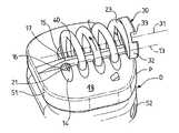
- FIGS. 1 and 2show two cross-sectional views of an embodiment of the system according to the invention for fixing a part to a bone element, FIG. 1 being a cross section designated I-I in FIG. 2 , and
- FIG. 2being a cross section designated II-II in FIG. 1 .
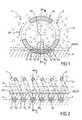
- FIGS. 3 and 4represent a cross-sectional view and a cavalier projection, respectively, of another embodiment of the system according to the invention in an application for fixing two plates of an intervertebral disk to the two vertebral bodies of two consecutive vertebrae.
- the present inventionconcerns system S for fixing a part P to a bone element Co.
- the part Pcomprises at least one through-hole 10 formed, for example, on an outer surface 18 , 18 ′, this through-hole having an axial line 10 x.
- the system Sis a rigid rod 20 comprising a first end 21 configured to penetrate into the element Co, the rod being wound into a spiral 22 substantially along a first helicoidal curve.
- the systemadditionally comprises means 30 for driving the rod 20 in rotation about the axis 31 of the first helicoidal curve in such a way that the first end 21 of the rod 20 moves alternately into the element Co and out of the element, and that, in its movement of rotation outside the element Co, the first end 21 of the rod 20 , which for example is pointed or beveled, moves at least once into the through-hole 10 .
- the cross section of the through-hole 10can be circular and have a cross section slightly greater than the maximum cross section of the rod 20 .
- the rod 20moves only once into this hole.
- the first end 21 of the rodmoves, or can move, several times into the same through-hole.
- the systemcomprises a plurality of through-holes 10 , 11 , 12 , etc., as is illustrated in all the figures, these being formed in the part P and each having an axial line 10 x , 11 x , 12 x , etc., respectively.
- the axial lines 10 x , 11 x , 12 x , etc., of these through-holesare substantially defined along a second helicoidal curve, the cross section of the holes of this plurality being at least equal to the maximum cross section of the rod 20 in such a way that the rod can slide relatively easily therein.
- the through-holes 10 , 11 , 12 , etc.are formed in the part P in such a way that their axial lines 10 x , 11 x , 12 x , etc., are all substantially perpendicular to the same straight line 13 , which is itself parallel to the axis 31 , in order to promote penetration of the rod 20 into the bone and help it move more easily into these holes.
- the systemadditionally comprises, as is illustrated in the figures, a projecting rib 40 formed on the part P and able to cooperate, for example by plug-type engagement, with a complementary groove formed beforehand in the bone element Co.
- the height of the rib, taken from the edges of the through-holes,is of course less than the internal diameter of the spiral 22 .
- the rib 40is formed along an axial line substantially parallel to the axis 31 and is substantially contained within a plane defined by the straight line 13 and the axis 31 of the second helicoidal curve in spiral form 22 .
- This rib 40makes it possible to improve the hold in terms of the cooperation between the walls of the through-holes and the spiral 22 .
- the cross section of the rod 20has substantially the shape of a rectangular quadrilateral, for example a square or a rectangle, if appropriate a trapezoid whose large base is little different than the small one and whose shape may then be similar to that of a rectangle.
- first and second helicoidal curves defined aboveare advantageously substantially identical and preferably have a constant pitch.
- the through-hole or through-holes 10 , 11 , 12 , etc.comprise(s) in each case at least one ramp 14 , 15 bordering at least one end 16 , 17 , respectively, of each through-hole in order to guide the movement of the first end 21 of said rod 20 into said holes.
- the axial lines 10 x , 11 x , 12 x , etc.while remaining perpendicular to the straight line 13 , are rounded transversely on a radius of curvature greater than the outer radius of the spiral 22 , as can be seen from FIG. 1 .
- the systemadvantageously comprises ramps 14 , 15 which border, respectively, each of the two ends 16 , 17 of each through-hole.
- the systemcomprises means 30 for driving the rod 20 in rotation about the axis 31 of the second helicoidal curve.
- These meanscan, for example, consist of the second end 23 of the rod 20 in spiral form 22 .
- the head 32has an annular shape whose internal and external diameters are substantially equal to the internal and external diameters of the spiral 22 , it thus being possible to simultaneously form the spiral 22 and the head 32 , by machining of a cylindrical tube made of titanium or the like.
- This embodiment of the head in an annular shapealso affords an advantage when fitting the spiral in place. This is because the head then serves as an abutment for defining the limit position of the spiral 22 relative to the part P, as is illustrated in FIGS. 3 and 4 .
- the number of holes 10 , 11 , 12 , etc.is substantially equal to the number of turns of the spiral 22 , by which means it is possible to obtain relatively good fixation of the part P on the bone element Co, with a minimum length of the spiral.
- the system according to the inventioncan be used in numerous fields, but it is particularly advantageous for procedures for fixing interbody cages or intervertebral disks.
- the spiral of the prosthesisis screwed into the thread.
- FIGS. 3 and 4show, by way of example, the system according to the invention used for fixing the two plates 51 , 52 of an artificial intervertebral disk D, cooperating with one another by hinge means 53 or similar, respectively to the two vertebral bodies of two consecutive vertebrae.
- an artificial intervertebral disk DWhen, for example, it is necessary to implant an artificial intervertebral disk D between two vertebral bodies, it is introduced by sliding it between the two vertebral bodies, which if necessary have first been subjected to a slight distraction. Two helicoidal rods in spiral form 22 are then introduced, as has been described above, by moving alternately into the bone of the vertebral bodies and respectively into the through-holes of each plate of the intervertebral disk, the first end 21 of each rod moving into a hole 10 , 11 , 12 , etc., upon each complete turn of the spiral when the rod is driven in rotation by the head 32 .
- the arrow 19illustrates the direction in which the spiral 22 is screwed into the vertebral structure for implantation of the system S.
- the system according to the inventionwill be used, in the same way as described above, for fixing at least one of the two opposite outer surfaces of an interbody cage to at least one of the two vertebral bodies of two consecutive vertebrae, the through-holes being formed on the opposite faces of the cage.
- fixation system described abovehas two important advantages compared to those systems of the prior art which only comprised spikes and/or ribs, if appropriate with products promoting osteosynthesis between the opposing faces coming into contact, respectively, with the plates and the vertebral bodies.
- the first of these two advantagesis the fact that it is therefore possible to introduce the intervertebral disk or the cage without having to ensure considerable distraction between the two vertebral bodies, whereas, with the systems of the prior art, it was necessary for the two vertebral bodies to undergo distraction by at least a value twice the height of the spikes and/or ribs.
- fixationmakes it possible to obtain what technicians call primary stability, which allows the patient to make movements not permissible with the systems of the prior art which required waiting for extensive consolidation of the bone to take place, generally a period of the order of several weeks.
- the spiralis simply unscrewed by turning the cage in the direction opposite to the arrow 19 . It is not necessary to break the bone element in order to free the spiral 22 .
Landscapes
- Health & Medical Sciences (AREA)
- Engineering & Computer Science (AREA)
- Biomedical Technology (AREA)
- Neurology (AREA)
- Orthopedic Medicine & Surgery (AREA)
- Cardiology (AREA)
- Oral & Maxillofacial Surgery (AREA)
- Transplantation (AREA)
- Heart & Thoracic Surgery (AREA)
- Vascular Medicine (AREA)
- Life Sciences & Earth Sciences (AREA)
- Animal Behavior & Ethology (AREA)
- General Health & Medical Sciences (AREA)
- Public Health (AREA)
- Veterinary Medicine (AREA)
- Prostheses (AREA)
Abstract
Description
- a rod comprising a first end, said rod being wound into a spiral substantially along a first helicoidal curve with respect to a longitudinal axis, and
- at least one through-hole made in said part and having an axial line,
- means for driving said rod in rotation about the axis of said first helicoidal curve in such a way that the first end of said rod moves alternately into the element and out of said element and that, in its movement of rotation, said first end of the rod moves at least once into said through-hole.
Claims (19)
Applications Claiming Priority (4)
| Application Number | Priority Date | Filing Date | Title |
|---|---|---|---|
| FR0201654 | 2002-02-11 | ||
| FR0201654AFR2835739B1 (en) | 2002-02-11 | 2002-02-11 | SYSTEM FOR FIXING A WORKPIECE ON A BONE BODY |
| FR02/01654 | 2002-02-11 | ||
| PCT/FR2003/000438WO2003068112A1 (en) | 2002-02-11 | 2003-02-11 | System for fixing a part to a bone element |
Publications (2)
| Publication Number | Publication Date |
|---|---|
| US20050143733A1 US20050143733A1 (en) | 2005-06-30 |
| US8142504B2true US8142504B2 (en) | 2012-03-27 |
Family
ID=27620088
Family Applications (1)
| Application Number | Title | Priority Date | Filing Date |
|---|---|---|---|
| US10/504,388Active2026-10-22US8142504B2 (en) | 2002-02-11 | 2003-02-11 | System for fixing a part to a bone element |
Country Status (4)
| Country | Link |
|---|---|
| US (1) | US8142504B2 (en) |
| AU (1) | AU2003226878A1 (en) |
| FR (1) | FR2835739B1 (en) |
| WO (1) | WO2003068112A1 (en) |
Cited By (6)
| Publication number | Priority date | Publication date | Assignee | Title |
|---|---|---|---|---|
| US20130261746A1 (en)* | 2012-03-28 | 2013-10-03 | Linares Medical Devices, Llc | Implantable inter-vertebral disk having upper and lower layers of a metal exhibiting bone fusing characteristics and which sandwich therebetween a soft plastic cushioning disc for providing dynamic properties mimicking that of a natural inter-vertebral disc |
| US20150327859A1 (en)* | 1998-09-18 | 2015-11-19 | Medtronic Vascular, Inc. | Surgical Fastener Assembly for Attaching a Prosthesis |
| US9750616B2 (en) | 2012-02-17 | 2017-09-05 | Spinal Elements, Inc. | Interbody fusion device |
| US10342678B2 (en) | 2015-02-02 | 2019-07-09 | Spinal Elements, Inc. | Interbody implant inserter |
| US11273058B2 (en) | 2019-05-07 | 2022-03-15 | Spinal Elements, Inc. | Cervical plate and inserter |
| US20220151664A1 (en)* | 2015-04-16 | 2022-05-19 | Texas Tech University System | Ankle (Tibio-Talar) Fusion Nail |
Families Citing this family (31)
| Publication number | Priority date | Publication date | Assignee | Title |
|---|---|---|---|---|
| FR2897259B1 (en) | 2006-02-15 | 2008-05-09 | Ldr Medical Soc Par Actions Si | INTERSOMATIC TRANSFORAMINAL CAGE WITH INTERBREBAL FUSION GRAFT AND CAGE IMPLANTATION INSTRUMENT |
| FR2824261B1 (en) | 2001-05-04 | 2004-05-28 | Ldr Medical | INTERVERTEBRAL DISC PROSTHESIS AND IMPLEMENTATION METHOD AND TOOLS |
| FR2827156B1 (en) | 2001-07-13 | 2003-11-14 | Ldr Medical | VERTEBRAL CAGE DEVICE WITH MODULAR FASTENING |
| FR2846550B1 (en) | 2002-11-05 | 2006-01-13 | Ldr Medical | INTERVERTEBRAL DISC PROSTHESIS |
| EP1610740A4 (en) | 2003-04-04 | 2009-04-08 | Theken Disc Llc | Artificial disc prosthesis |
| FR2865629B1 (en) | 2004-02-04 | 2007-01-26 | Ldr Medical | INTERVERTEBRAL DISC PROSTHESIS |
| EP2113227B1 (en) | 2004-02-04 | 2015-07-29 | LDR Medical | Intervertebral disc prosthesis |
| FR2869528B1 (en) | 2004-04-28 | 2007-02-02 | Ldr Medical | INTERVERTEBRAL DISC PROSTHESIS |
| US7544208B1 (en) | 2004-05-03 | 2009-06-09 | Theken Spine, Llc | Adjustable corpectomy apparatus |
| FR2879436B1 (en) | 2004-12-22 | 2007-03-09 | Ldr Medical | INTERVERTEBRAL DISC PROSTHESIS |
| FR2891135B1 (en) | 2005-09-23 | 2008-09-12 | Ldr Medical Sarl | INTERVERTEBRAL DISC PROSTHESIS |
| FR2893838B1 (en) | 2005-11-30 | 2008-08-08 | Ldr Medical Soc Par Actions Si | PROSTHESIS OF INTERVERTEBRAL DISC AND INSTRUMENTATION OF INSERTION OF THE PROSTHESIS BETWEEN VERTEBRATES |
| US8465546B2 (en) | 2007-02-16 | 2013-06-18 | Ldr Medical | Intervertebral disc prosthesis insertion assemblies |
| FR2916956B1 (en)* | 2007-06-08 | 2012-12-14 | Ldr Medical | INTERSOMATIC CAGE, INTERVERTEBRAL PROSTHESIS, ANCHORING DEVICE AND IMPLANTATION INSTRUMENTATION |
| CN105326585B (en) | 2009-09-17 | 2018-12-11 | Ldr控股公司 | Intervertebral implant with extensible bone anchoring element |
| WO2011080535A1 (en) | 2009-12-31 | 2011-07-07 | Lrd Medical | Anchoring device, intervertebral implant and implantation instrument |
| WO2012148838A1 (en) | 2011-04-26 | 2012-11-01 | Alphatec Spine, Inc. | Stand alone interbody fixation system |
| FR2987256B1 (en) | 2012-02-24 | 2014-08-08 | Ldr Medical | ANCHORING DEVICE FOR INTERVERTEBRAL IMPLANT, INTERVERTEBRAL IMPLANT AND IMPLANTATION INSTRUMENTATION |
| US9456904B2 (en)* | 2012-10-23 | 2016-10-04 | Spinesmith Partners, L.P. | Facet fixation device |
| FR3005569B1 (en) | 2013-05-16 | 2021-09-03 | Ldr Medical | VERTEBRAL IMPLANT, VERTEBRAL IMPLANT FIXATION DEVICE AND IMPLANTATION INSTRUMENTATION |
| FR3016793B1 (en) | 2014-01-30 | 2021-05-07 | Ldr Medical | ANCHORING DEVICE FOR SPINAL IMPLANT, SPINAL IMPLANT AND IMPLANTATION INSTRUMENTATION |
| FR3020756B1 (en) | 2014-05-06 | 2022-03-11 | Ldr Medical | VERTEBRAL IMPLANT, VERTEBRAL IMPLANT FIXATION DEVICE AND IMPLANT INSTRUMENTATION |
| JP6768001B2 (en) | 2015-04-29 | 2020-10-14 | インスティテュート フォー マスキュロスケレタル サイエンス アンド エジュケイション,リミテッド | Coiled implants and systems and how to make them |
| US10492921B2 (en) | 2015-04-29 | 2019-12-03 | Institute for Musculoskeletal Science and Education, Ltd. | Implant with arched bone contacting elements |
| US10449051B2 (en)* | 2015-04-29 | 2019-10-22 | Institute for Musculoskeletal Science and Education, Ltd. | Implant with curved bone contacting elements |
| US10166116B2 (en)* | 2015-12-02 | 2019-01-01 | Brian Patrick Janowski | Helical lock spacer, instruments and methods |
| US11033394B2 (en) | 2016-10-25 | 2021-06-15 | Institute for Musculoskeletal Science and Education, Ltd. | Implant with multi-layer bone interfacing lattice |
| US10478312B2 (en) | 2016-10-25 | 2019-11-19 | Institute for Musculoskeletal Science and Education, Ltd. | Implant with protected fusion zones |
| US10512549B2 (en) | 2017-03-13 | 2019-12-24 | Institute for Musculoskeletal Science and Education, Ltd. | Implant with structural members arranged around a ring |
| US10940015B2 (en) | 2017-11-21 | 2021-03-09 | Institute for Musculoskeletal Science and Education, Ltd. | Implant with improved flow characteristics |
| US10744001B2 (en) | 2017-11-21 | 2020-08-18 | Institute for Musculoskeletal Science and Education, Ltd. | Implant with improved bone contact |
Citations (10)
| Publication number | Priority date | Publication date | Assignee | Title |
|---|---|---|---|---|
| US4038703A (en) | 1975-11-14 | 1977-08-02 | General Atomic Company | Prosthetic devices having a region of controlled porosity |
| US5263953A (en) | 1991-12-31 | 1993-11-23 | Spine-Tech, Inc. | Apparatus and system for fusing bone joints |
| US5423817A (en) | 1993-07-29 | 1995-06-13 | Lin; Chih-I | Intervertebral fusing device |
| US5662683A (en)* | 1995-08-22 | 1997-09-02 | Ortho Helix Limited | Open helical organic tissue anchor and method of facilitating healing |
| WO1998002117A1 (en) | 1996-07-15 | 1998-01-22 | Aesculap Ag & Co. Kg | Implant for vertebral body fusion |
| WO1998048738A1 (en) | 1997-04-25 | 1998-11-05 | Stryker France S.A. | Two-part intersomatic implant |
| US6143032A (en)* | 1997-11-12 | 2000-11-07 | Schafer Micomed Gmbh | Intervertebral implant |
| FR2812188A1 (en) | 2000-07-31 | 2002-02-01 | Spinevision Sa | RACHIS IMMOBILIZATION CAGE AND OSTEOSYNTHESIS, METHOD FOR MANUFACTURING THE CAGE AND DRILLING EQUIPMENT FOR THE LAYOUT OF THE CAGE |
| US20020055737A1 (en)* | 2000-11-08 | 2002-05-09 | The Cleveland Clinic Foundation | Apparatus for implantation into bone related applications |
| US6758849B1 (en)* | 1995-02-17 | 2004-07-06 | Sdgi Holdings, Inc. | Interbody spinal fusion implants |
Family Cites Families (1)
| Publication number | Priority date | Publication date | Assignee | Title |
|---|---|---|---|---|
| US5433817A (en)* | 1993-09-30 | 1995-07-18 | Fabio Perini S.P.A. | Ply-bonding device for bonding plies of paper webs and like material |
- 2002
- 2002-02-11FRFR0201654Apatent/FR2835739B1/ennot_activeExpired - Fee Related
- 2003
- 2003-02-11AUAU2003226878Apatent/AU2003226878A1/ennot_activeAbandoned
- 2003-02-11WOPCT/FR2003/000438patent/WO2003068112A1/ennot_activeApplication Discontinuation
- 2003-02-11USUS10/504,388patent/US8142504B2/enactiveActive
Patent Citations (11)
| Publication number | Priority date | Publication date | Assignee | Title |
|---|---|---|---|---|
| US4038703A (en) | 1975-11-14 | 1977-08-02 | General Atomic Company | Prosthetic devices having a region of controlled porosity |
| US5263953A (en) | 1991-12-31 | 1993-11-23 | Spine-Tech, Inc. | Apparatus and system for fusing bone joints |
| US5423817A (en) | 1993-07-29 | 1995-06-13 | Lin; Chih-I | Intervertebral fusing device |
| US6758849B1 (en)* | 1995-02-17 | 2004-07-06 | Sdgi Holdings, Inc. | Interbody spinal fusion implants |
| US5662683A (en)* | 1995-08-22 | 1997-09-02 | Ortho Helix Limited | Open helical organic tissue anchor and method of facilitating healing |
| WO1998002117A1 (en) | 1996-07-15 | 1998-01-22 | Aesculap Ag & Co. Kg | Implant for vertebral body fusion |
| WO1998048738A1 (en) | 1997-04-25 | 1998-11-05 | Stryker France S.A. | Two-part intersomatic implant |
| US6143032A (en)* | 1997-11-12 | 2000-11-07 | Schafer Micomed Gmbh | Intervertebral implant |
| FR2812188A1 (en) | 2000-07-31 | 2002-02-01 | Spinevision Sa | RACHIS IMMOBILIZATION CAGE AND OSTEOSYNTHESIS, METHOD FOR MANUFACTURING THE CAGE AND DRILLING EQUIPMENT FOR THE LAYOUT OF THE CAGE |
| US20020055737A1 (en)* | 2000-11-08 | 2002-05-09 | The Cleveland Clinic Foundation | Apparatus for implantation into bone related applications |
| US6544265B2 (en)* | 2000-11-08 | 2003-04-08 | The Cleveland Clinic Foundation | Apparatus for implantation into bone related applications |
Cited By (12)
| Publication number | Priority date | Publication date | Assignee | Title |
|---|---|---|---|---|
| US20150327859A1 (en)* | 1998-09-18 | 2015-11-19 | Medtronic Vascular, Inc. | Surgical Fastener Assembly for Attaching a Prosthesis |
| US9750616B2 (en) | 2012-02-17 | 2017-09-05 | Spinal Elements, Inc. | Interbody fusion device |
| US10675156B2 (en) | 2012-02-17 | 2020-06-09 | Spinal Elements, Inc. | Interbody fusion device |
| US11351038B2 (en) | 2012-02-17 | 2022-06-07 | Spinal Elements, Inc. | Interbody fusion device |
| US20130261746A1 (en)* | 2012-03-28 | 2013-10-03 | Linares Medical Devices, Llc | Implantable inter-vertebral disk having upper and lower layers of a metal exhibiting bone fusing characteristics and which sandwich therebetween a soft plastic cushioning disc for providing dynamic properties mimicking that of a natural inter-vertebral disc |
| US10342678B2 (en) | 2015-02-02 | 2019-07-09 | Spinal Elements, Inc. | Interbody implant inserter |
| US11224524B2 (en) | 2015-02-02 | 2022-01-18 | Spinal Elements, Inc. | Interbody implant inserter |
| US11890206B2 (en) | 2015-02-02 | 2024-02-06 | Spinal Elements, Inc. | Interbody implant inserter |
| US20220151664A1 (en)* | 2015-04-16 | 2022-05-19 | Texas Tech University System | Ankle (Tibio-Talar) Fusion Nail |
| US11273058B2 (en) | 2019-05-07 | 2022-03-15 | Spinal Elements, Inc. | Cervical plate and inserter |
| US11911294B2 (en) | 2019-05-07 | 2024-02-27 | Spinal Elements, Inc. | Cervical plate and inserter |
| US12318123B2 (en) | 2019-05-07 | 2025-06-03 | Spinal Elements, Inc. | Cervical plate and inserter |
Also Published As
| Publication number | Publication date |
|---|---|
| FR2835739B1 (en) | 2004-05-14 |
| AU2003226878A1 (en) | 2003-09-04 |
| WO2003068112A1 (en) | 2003-08-21 |
| US20050143733A1 (en) | 2005-06-30 |
| FR2835739A1 (en) | 2003-08-15 |
Similar Documents
| Publication | Publication Date | Title |
|---|---|---|
| US8142504B2 (en) | System for fixing a part to a bone element | |
| US11564803B2 (en) | Expandable vertebral implant | |
| KR100553297B1 (en) | Intracavity implant consisting of two parts | |
| US20210000608A1 (en) | Facet joint implant | |
| US6908485B2 (en) | Implant for replacing a vertebra | |
| US6306136B1 (en) | Implant, in particular front cervical plate | |
| US8979927B2 (en) | Spinal implant with staples | |
| US6648885B1 (en) | Device for the osteosynthesis of a spinal segment | |
| US8435299B2 (en) | Expandable osteosynthesis cage | |
| US8100972B1 (en) | Spinal cage having deployable member | |
| EP2845552A1 (en) | Implant for treating the spine | |
| JP2008505708A (en) | Skeletal reconstruction device | |
| US11547573B2 (en) | Expandable interbody implant with teeth driven linkages | |
| MXPA00007482A (en) | Implant for replacing a vertebra |
Legal Events
| Date | Code | Title | Description |
|---|---|---|---|
| AS | Assignment | Owner name:SPINEVISION, FRANCE Free format text:ASSIGNMENT OF ASSIGNORS INTEREST;ASSIGNOR:PETIT, DOMINIQUE;REEL/FRAME:016349/0813 Effective date:20040805 | |
| STCF | Information on status: patent grant | Free format text:PATENTED CASE | |
| AS | Assignment | Owner name:NORGINE B.V., NETHERLANDS Free format text:LIEN;ASSIGNOR:SPINEVISION;REEL/FRAME:033960/0774 Effective date:20140926 Owner name:NORGINE PHARMA, FRANCE Free format text:LIEN;ASSIGNOR:SPINEVISION;REEL/FRAME:033960/0774 Effective date:20140926 | |
| AS | Assignment | Owner name:NORGINE B.V., NETHERLANDS Free format text:CORRECTIVE ASSIGNMENT TO CORRECT THE ASSIGNEE NAME PREVIOUSLY RECORDED AT REEL: 033960 FRAME: 0774. ASSIGNOR(S) HEREBY CONFIRMS THE ASSIGNMENT;ASSIGNOR:SPINEVISION;REEL/FRAME:034056/0330 Effective date:20140926 | |
| AS | Assignment | Owner name:NORGINE B.V., NETHERLANDS Free format text:LIEN;ASSIGNOR:SPINEVISION;REEL/FRAME:034977/0225 Effective date:20150129 | |
| FPAY | Fee payment | Year of fee payment:4 | |
| AS | Assignment | Owner name:NORGINE VENTURES B.V, NETHERLANDS Free format text:ASSIGNMENT OF ASSIGNORS INTEREST;ASSIGNOR:NORGINE B.V;REEL/FRAME:038897/0605 Effective date:20160610 | |
| MAFP | Maintenance fee payment | Free format text:PAYMENT OF MAINTENANCE FEE, 8TH YEAR, LARGE ENTITY (ORIGINAL EVENT CODE: M1552); ENTITY STATUS OF PATENT OWNER: LARGE ENTITY Year of fee payment:8 | |
| MAFP | Maintenance fee payment | Free format text:PAYMENT OF MAINTENANCE FEE, 12TH YEAR, LARGE ENTITY (ORIGINAL EVENT CODE: M1553); ENTITY STATUS OF PATENT OWNER: LARGE ENTITY Year of fee payment:12 |