US8142493B2 - Method of heart valve repair - Google Patents
Method of heart valve repairDownload PDFInfo
- Publication number
- US8142493B2 US8142493B2US12/177,554US17755408AUS8142493B2US 8142493 B2US8142493 B2US 8142493B2US 17755408 AUS17755408 AUS 17755408AUS 8142493 B2US8142493 B2US 8142493B2
- Authority
- US
- United States
- Prior art keywords
- annulus
- catheter
- fastener
- fasteners
- tissue
- Prior art date
- Legal status (The legal status is an assumption and is not a legal conclusion. Google has not performed a legal analysis and makes no representation as to the accuracy of the status listed.)
- Expired - Fee Related, expires
Links
- 238000000034methodMethods0.000titleclaimsabstractdescription53
- 210000003709heart valveAnatomy0.000titledescription10
- 230000008439repair processEffects0.000titledescription2
- 210000004115mitral valveAnatomy0.000claimsabstractdescription88
- 210000003748coronary sinusAnatomy0.000claimsdescription128
- 239000008280bloodSubstances0.000claimsdescription10
- 210000004369bloodAnatomy0.000claimsdescription10
- 238000004873anchoringMethods0.000claimsdescription7
- 206010067171RegurgitationDiseases0.000claimsdescription5
- 210000001519tissueAnatomy0.000description91
- 210000005240left ventricleAnatomy0.000description53
- 210000005246left atriumAnatomy0.000description27
- 230000008878couplingEffects0.000description26
- 238000010168coupling processMethods0.000description26
- 238000005859coupling reactionMethods0.000description26
- 230000007246mechanismEffects0.000description20
- 238000001356surgical procedureMethods0.000description18
- 206010019280Heart failuresDiseases0.000description14
- 206010027727Mitral valve incompetenceDiseases0.000description13
- 208000005907mitral valve insufficiencyDiseases0.000description13
- 206010007559Cardiac failure congestiveDiseases0.000description11
- 210000005003heart tissueAnatomy0.000description11
- 230000001746atrial effectEffects0.000description9
- 238000002788crimpingMethods0.000description9
- 239000004744fabricSubstances0.000description9
- 238000005520cutting processMethods0.000description8
- 238000002560therapeutic procedureMethods0.000description8
- 230000002861ventricularEffects0.000description7
- 208000016569congenital mitral valve insufficiencyDiseases0.000description6
- 230000033001locomotionEffects0.000description6
- 238000011282treatmentMethods0.000description6
- 230000009471actionEffects0.000description5
- 239000003146anticoagulant agentSubstances0.000description5
- 229940127219anticoagulant drugDrugs0.000description5
- 230000008901benefitEffects0.000description5
- 238000002513implantationMethods0.000description5
- 210000003484anatomyAnatomy0.000description4
- 210000001765aortic valveAnatomy0.000description4
- 230000009467reductionEffects0.000description4
- 230000000717retained effectEffects0.000description4
- 238000004904shorteningMethods0.000description4
- 210000001562sternumAnatomy0.000description4
- 208000024891symptomDiseases0.000description4
- 210000000709aortaAnatomy0.000description3
- 238000013459approachMethods0.000description3
- 238000002847impedance measurementMethods0.000description3
- 238000012977invasive surgical procedureMethods0.000description3
- 230000000452restraining effectEffects0.000description3
- 229910001285shape-memory alloyInorganic materials0.000description3
- 230000000087stabilizing effectEffects0.000description3
- 208000012287ProlapseDiseases0.000description2
- 208000007536ThrombosisDiseases0.000description2
- 208000027418Wounds and injuryDiseases0.000description2
- 230000036772blood pressureEffects0.000description2
- 210000005242cardiac chamberAnatomy0.000description2
- 230000010339dilationEffects0.000description2
- 230000000694effectsEffects0.000description2
- 230000006870functionEffects0.000description2
- 238000003780insertionMethods0.000description2
- 230000037431insertionEffects0.000description2
- 239000000463materialSubstances0.000description2
- 229910052751metalInorganic materials0.000description2
- 239000002184metalSubstances0.000description2
- 230000004048modificationEffects0.000description2
- 238000012986modificationMethods0.000description2
- 210000003540papillary muscleAnatomy0.000description2
- 230000007480spreadingEffects0.000description2
- 238000003892spreadingMethods0.000description2
- 208000006029CardiomegalyDiseases0.000description1
- 208000031229CardiomyopathiesDiseases0.000description1
- 206010010356Congenital anomalyDiseases0.000description1
- 229920004934Dacron®Polymers0.000description1
- 208000005189EmbolismDiseases0.000description1
- CWYNVVGOOAEACU-UHFFFAOYSA-NFe2+Chemical compound[Fe+2]CWYNVVGOOAEACU-UHFFFAOYSA-N0.000description1
- 241000270923Hesperostipa comataSpecies0.000description1
- 241001465754MetazoaSpecies0.000description1
- 208000003430Mitral Valve ProlapseDiseases0.000description1
- 229910000639Spring steelInorganic materials0.000description1
- 241000282887SuidaeSpecies0.000description1
- 208000001435ThromboembolismDiseases0.000description1
- HZEWFHLRYVTOIW-UHFFFAOYSA-N[Ti].[Ni]Chemical compound[Ti].[Ni]HZEWFHLRYVTOIW-UHFFFAOYSA-N0.000description1
- 230000004913activationEffects0.000description1
- 230000001154acute effectEffects0.000description1
- 239000000560biocompatible materialSubstances0.000description1
- 230000000740bleeding effectEffects0.000description1
- 230000017531blood circulationEffects0.000description1
- 230000000747cardiac effectEffects0.000description1
- 230000002612cardiopulmonary effectEffects0.000description1
- 210000000038chestAnatomy0.000description1
- 230000006835compressionEffects0.000description1
- 238000007906compressionMethods0.000description1
- 230000008602contractionEffects0.000description1
- 238000007796conventional methodMethods0.000description1
- 238000012937correctionMethods0.000description1
- 230000003247decreasing effectEffects0.000description1
- 230000009429distressEffects0.000description1
- 230000004064dysfunctionEffects0.000description1
- -1e.g.Substances0.000description1
- 239000013013elastic materialSubstances0.000description1
- 230000003073embolic effectEffects0.000description1
- 238000010304firingMethods0.000description1
- 210000002837heart atriumAnatomy0.000description1
- 230000004217heart functionEffects0.000description1
- 230000006872improvementEffects0.000description1
- 208000015181infectious diseaseDiseases0.000description1
- 208000014674injuryDiseases0.000description1
- 208000023589ischemic diseaseDiseases0.000description1
- 230000007774longtermEffects0.000description1
- 230000036244malformationEffects0.000description1
- 238000004519manufacturing processMethods0.000description1
- 238000005259measurementMethods0.000description1
- 239000012528membraneSubstances0.000description1
- 230000003446memory effectEffects0.000description1
- 230000003387muscularEffects0.000description1
- 208000010125myocardial infarctionDiseases0.000description1
- 230000007971neurological deficitEffects0.000description1
- 229910001000nickel titaniumInorganic materials0.000description1
- 230000000149penetrating effectEffects0.000description1
- 230000037081physical activityEffects0.000description1
- 239000004033plasticSubstances0.000description1
- 239000005020polyethylene terephthalateSubstances0.000description1
- 229920000642polymerPolymers0.000description1
- 239000002861polymer materialSubstances0.000description1
- 239000002243precursorSubstances0.000description1
- 230000008569processEffects0.000description1
- 230000000750progressive effectEffects0.000description1
- 238000011084recoveryMethods0.000description1
- 230000003014reinforcing effectEffects0.000description1
- 230000001846repelling effectEffects0.000description1
- 238000012552reviewMethods0.000description1
- 238000009958sewingMethods0.000description1
- 239000007787solidSubstances0.000description1
- 239000007858starting materialSubstances0.000description1
- 230000035882stressEffects0.000description1
- 238000011477surgical interventionMethods0.000description1
- 239000003356suture materialSubstances0.000description1
- 230000008733traumaEffects0.000description1
Images


Classifications
- A—HUMAN NECESSITIES
- A61—MEDICAL OR VETERINARY SCIENCE; HYGIENE
- A61F—FILTERS IMPLANTABLE INTO BLOOD VESSELS; PROSTHESES; DEVICES PROVIDING PATENCY TO, OR PREVENTING COLLAPSING OF, TUBULAR STRUCTURES OF THE BODY, e.g. STENTS; ORTHOPAEDIC, NURSING OR CONTRACEPTIVE DEVICES; FOMENTATION; TREATMENT OR PROTECTION OF EYES OR EARS; BANDAGES, DRESSINGS OR ABSORBENT PADS; FIRST-AID KITS
- A61F2/00—Filters implantable into blood vessels; Prostheses, i.e. artificial substitutes or replacements for parts of the body; Appliances for connecting them with the body; Devices providing patency to, or preventing collapsing of, tubular structures of the body, e.g. stents
- A61F2/02—Prostheses implantable into the body
- A61F2/24—Heart valves ; Vascular valves, e.g. venous valves; Heart implants, e.g. passive devices for improving the function of the native valve or the heart muscle; Transmyocardial revascularisation [TMR] devices; Valves implantable in the body
- A61F2/2442—Annuloplasty rings or inserts for correcting the valve shape; Implants for improving the function of a native heart valve
- A61F2/2466—Delivery devices therefor
- A—HUMAN NECESSITIES
- A61—MEDICAL OR VETERINARY SCIENCE; HYGIENE
- A61B—DIAGNOSIS; SURGERY; IDENTIFICATION
- A61B17/00—Surgical instruments, devices or methods
- A61B17/04—Surgical instruments, devices or methods for suturing wounds; Holders or packages for needles or suture materials
- A61B17/0401—Suture anchors, buttons or pledgets, i.e. means for attaching sutures to bone, cartilage or soft tissue; Instruments for applying or removing suture anchors
- A—HUMAN NECESSITIES
- A61—MEDICAL OR VETERINARY SCIENCE; HYGIENE
- A61B—DIAGNOSIS; SURGERY; IDENTIFICATION
- A61B17/00—Surgical instruments, devices or methods
- A61B17/04—Surgical instruments, devices or methods for suturing wounds; Holders or packages for needles or suture materials
- A61B17/0469—Suturing instruments for use in minimally invasive surgery, e.g. endoscopic surgery
- A—HUMAN NECESSITIES
- A61—MEDICAL OR VETERINARY SCIENCE; HYGIENE
- A61B—DIAGNOSIS; SURGERY; IDENTIFICATION
- A61B17/00—Surgical instruments, devices or methods
- A61B17/04—Surgical instruments, devices or methods for suturing wounds; Holders or packages for needles or suture materials
- A61B17/0482—Needle or suture guides
- A—HUMAN NECESSITIES
- A61—MEDICAL OR VETERINARY SCIENCE; HYGIENE
- A61F—FILTERS IMPLANTABLE INTO BLOOD VESSELS; PROSTHESES; DEVICES PROVIDING PATENCY TO, OR PREVENTING COLLAPSING OF, TUBULAR STRUCTURES OF THE BODY, e.g. STENTS; ORTHOPAEDIC, NURSING OR CONTRACEPTIVE DEVICES; FOMENTATION; TREATMENT OR PROTECTION OF EYES OR EARS; BANDAGES, DRESSINGS OR ABSORBENT PADS; FIRST-AID KITS
- A61F2/00—Filters implantable into blood vessels; Prostheses, i.e. artificial substitutes or replacements for parts of the body; Appliances for connecting them with the body; Devices providing patency to, or preventing collapsing of, tubular structures of the body, e.g. stents
- A61F2/02—Prostheses implantable into the body
- A61F2/24—Heart valves ; Vascular valves, e.g. venous valves; Heart implants, e.g. passive devices for improving the function of the native valve or the heart muscle; Transmyocardial revascularisation [TMR] devices; Valves implantable in the body
- A61F2/2442—Annuloplasty rings or inserts for correcting the valve shape; Implants for improving the function of a native heart valve
- A61F2/2445—Annuloplasty rings in direct contact with the valve annulus
- A—HUMAN NECESSITIES
- A61—MEDICAL OR VETERINARY SCIENCE; HYGIENE
- A61F—FILTERS IMPLANTABLE INTO BLOOD VESSELS; PROSTHESES; DEVICES PROVIDING PATENCY TO, OR PREVENTING COLLAPSING OF, TUBULAR STRUCTURES OF THE BODY, e.g. STENTS; ORTHOPAEDIC, NURSING OR CONTRACEPTIVE DEVICES; FOMENTATION; TREATMENT OR PROTECTION OF EYES OR EARS; BANDAGES, DRESSINGS OR ABSORBENT PADS; FIRST-AID KITS
- A61F2/00—Filters implantable into blood vessels; Prostheses, i.e. artificial substitutes or replacements for parts of the body; Appliances for connecting them with the body; Devices providing patency to, or preventing collapsing of, tubular structures of the body, e.g. stents
- A61F2/02—Prostheses implantable into the body
- A61F2/24—Heart valves ; Vascular valves, e.g. venous valves; Heart implants, e.g. passive devices for improving the function of the native valve or the heart muscle; Transmyocardial revascularisation [TMR] devices; Valves implantable in the body
- A61F2/2442—Annuloplasty rings or inserts for correcting the valve shape; Implants for improving the function of a native heart valve
- A61F2/2451—Inserts in the coronary sinus for correcting the valve shape
- A—HUMAN NECESSITIES
- A61—MEDICAL OR VETERINARY SCIENCE; HYGIENE
- A61B—DIAGNOSIS; SURGERY; IDENTIFICATION
- A61B17/00—Surgical instruments, devices or methods
- A61B17/04—Surgical instruments, devices or methods for suturing wounds; Holders or packages for needles or suture materials
- A61B17/0487—Suture clamps, clips or locks, e.g. for replacing suture knots; Instruments for applying or removing suture clamps, clips or locks
- A—HUMAN NECESSITIES
- A61—MEDICAL OR VETERINARY SCIENCE; HYGIENE
- A61B—DIAGNOSIS; SURGERY; IDENTIFICATION
- A61B17/00—Surgical instruments, devices or methods
- A61B17/064—Surgical staples, i.e. penetrating the tissue
- A—HUMAN NECESSITIES
- A61—MEDICAL OR VETERINARY SCIENCE; HYGIENE
- A61B—DIAGNOSIS; SURGERY; IDENTIFICATION
- A61B17/00—Surgical instruments, devices or methods
- A61B2017/00367—Details of actuation of instruments, e.g. relations between pushing buttons, or the like, and activation of the tool, working tip, or the like
- A61B2017/00398—Details of actuation of instruments, e.g. relations between pushing buttons, or the like, and activation of the tool, working tip, or the like using powered actuators, e.g. stepper motors, solenoids
- A—HUMAN NECESSITIES
- A61—MEDICAL OR VETERINARY SCIENCE; HYGIENE
- A61B—DIAGNOSIS; SURGERY; IDENTIFICATION
- A61B17/00—Surgical instruments, devices or methods
- A61B2017/00831—Material properties
- A61B2017/00862—Material properties elastic or resilient
- A—HUMAN NECESSITIES
- A61—MEDICAL OR VETERINARY SCIENCE; HYGIENE
- A61B—DIAGNOSIS; SURGERY; IDENTIFICATION
- A61B17/00—Surgical instruments, devices or methods
- A61B2017/00831—Material properties
- A61B2017/00867—Material properties shape memory effect
- A—HUMAN NECESSITIES
- A61—MEDICAL OR VETERINARY SCIENCE; HYGIENE
- A61B—DIAGNOSIS; SURGERY; IDENTIFICATION
- A61B17/00—Surgical instruments, devices or methods
- A61B2017/00831—Material properties
- A61B2017/00876—Material properties magnetic
- A—HUMAN NECESSITIES
- A61—MEDICAL OR VETERINARY SCIENCE; HYGIENE
- A61B—DIAGNOSIS; SURGERY; IDENTIFICATION
- A61B17/00—Surgical instruments, devices or methods
- A61B17/04—Surgical instruments, devices or methods for suturing wounds; Holders or packages for needles or suture materials
- A61B17/0401—Suture anchors, buttons or pledgets, i.e. means for attaching sutures to bone, cartilage or soft tissue; Instruments for applying or removing suture anchors
- A61B2017/0406—Pledgets
- A—HUMAN NECESSITIES
- A61—MEDICAL OR VETERINARY SCIENCE; HYGIENE
- A61B—DIAGNOSIS; SURGERY; IDENTIFICATION
- A61B17/00—Surgical instruments, devices or methods
- A61B17/04—Surgical instruments, devices or methods for suturing wounds; Holders or packages for needles or suture materials
- A61B17/0401—Suture anchors, buttons or pledgets, i.e. means for attaching sutures to bone, cartilage or soft tissue; Instruments for applying or removing suture anchors
- A61B2017/0409—Instruments for applying suture anchors
- A—HUMAN NECESSITIES
- A61—MEDICAL OR VETERINARY SCIENCE; HYGIENE
- A61B—DIAGNOSIS; SURGERY; IDENTIFICATION
- A61B17/00—Surgical instruments, devices or methods
- A61B17/04—Surgical instruments, devices or methods for suturing wounds; Holders or packages for needles or suture materials
- A61B17/0401—Suture anchors, buttons or pledgets, i.e. means for attaching sutures to bone, cartilage or soft tissue; Instruments for applying or removing suture anchors
- A61B2017/0417—T-fasteners
- A—HUMAN NECESSITIES
- A61—MEDICAL OR VETERINARY SCIENCE; HYGIENE
- A61B—DIAGNOSIS; SURGERY; IDENTIFICATION
- A61B17/00—Surgical instruments, devices or methods
- A61B17/04—Surgical instruments, devices or methods for suturing wounds; Holders or packages for needles or suture materials
- A61B17/0401—Suture anchors, buttons or pledgets, i.e. means for attaching sutures to bone, cartilage or soft tissue; Instruments for applying or removing suture anchors
- A61B2017/0419—H-fasteners
- A—HUMAN NECESSITIES
- A61—MEDICAL OR VETERINARY SCIENCE; HYGIENE
- A61B—DIAGNOSIS; SURGERY; IDENTIFICATION
- A61B17/00—Surgical instruments, devices or methods
- A61B17/04—Surgical instruments, devices or methods for suturing wounds; Holders or packages for needles or suture materials
- A61B17/0401—Suture anchors, buttons or pledgets, i.e. means for attaching sutures to bone, cartilage or soft tissue; Instruments for applying or removing suture anchors
- A61B2017/0446—Means for attaching and blocking the suture in the suture anchor
- A61B2017/0454—Means for attaching and blocking the suture in the suture anchor the anchor being crimped or clamped on the suture
- A—HUMAN NECESSITIES
- A61—MEDICAL OR VETERINARY SCIENCE; HYGIENE
- A61B—DIAGNOSIS; SURGERY; IDENTIFICATION
- A61B17/00—Surgical instruments, devices or methods
- A61B17/04—Surgical instruments, devices or methods for suturing wounds; Holders or packages for needles or suture materials
- A61B17/0401—Suture anchors, buttons or pledgets, i.e. means for attaching sutures to bone, cartilage or soft tissue; Instruments for applying or removing suture anchors
- A61B2017/0446—Means for attaching and blocking the suture in the suture anchor
- A61B2017/0458—Longitudinal through hole, e.g. suture blocked by a distal suture knot
- A—HUMAN NECESSITIES
- A61—MEDICAL OR VETERINARY SCIENCE; HYGIENE
- A61B—DIAGNOSIS; SURGERY; IDENTIFICATION
- A61B17/00—Surgical instruments, devices or methods
- A61B17/04—Surgical instruments, devices or methods for suturing wounds; Holders or packages for needles or suture materials
- A61B17/0401—Suture anchors, buttons or pledgets, i.e. means for attaching sutures to bone, cartilage or soft tissue; Instruments for applying or removing suture anchors
- A61B2017/0464—Suture anchors, buttons or pledgets, i.e. means for attaching sutures to bone, cartilage or soft tissue; Instruments for applying or removing suture anchors for soft tissue
- A—HUMAN NECESSITIES
- A61—MEDICAL OR VETERINARY SCIENCE; HYGIENE
- A61B—DIAGNOSIS; SURGERY; IDENTIFICATION
- A61B17/00—Surgical instruments, devices or methods
- A61B17/04—Surgical instruments, devices or methods for suturing wounds; Holders or packages for needles or suture materials
- A61B2017/0496—Surgical instruments, devices or methods for suturing wounds; Holders or packages for needles or suture materials for tensioning sutures
- A—HUMAN NECESSITIES
- A61—MEDICAL OR VETERINARY SCIENCE; HYGIENE
- A61B—DIAGNOSIS; SURGERY; IDENTIFICATION
- A61B17/00—Surgical instruments, devices or methods
- A61B17/064—Surgical staples, i.e. penetrating the tissue
- A61B2017/0641—Surgical staples, i.e. penetrating the tissue having at least three legs as part of one single body
- A—HUMAN NECESSITIES
- A61—MEDICAL OR VETERINARY SCIENCE; HYGIENE
- A61B—DIAGNOSIS; SURGERY; IDENTIFICATION
- A61B17/00—Surgical instruments, devices or methods
- A61B17/064—Surgical staples, i.e. penetrating the tissue
- A61B2017/0647—Surgical staples, i.e. penetrating the tissue having one single leg, e.g. tacks
- Y—GENERAL TAGGING OF NEW TECHNOLOGICAL DEVELOPMENTS; GENERAL TAGGING OF CROSS-SECTIONAL TECHNOLOGIES SPANNING OVER SEVERAL SECTIONS OF THE IPC; TECHNICAL SUBJECTS COVERED BY FORMER USPC CROSS-REFERENCE ART COLLECTIONS [XRACs] AND DIGESTS
- Y10—TECHNICAL SUBJECTS COVERED BY FORMER USPC
- Y10S—TECHNICAL SUBJECTS COVERED BY FORMER USPC CROSS-REFERENCE ART COLLECTIONS [XRACs] AND DIGESTS
- Y10S623/00—Prosthesis, i.e. artificial body members, parts thereof, or aids and accessories therefor
- Y10S623/902—Method of implanting
- Y10S623/904—Heart
Definitions
- the present inventionrelates generally to techniques for treating mitral valve insufficiencies such as mitral valve leakage due to prolapse, papillary muscle dysfunction, or annular dilation. More particularly, the present invention relates to systems and methods for treating a leaking mitral valve in a minimally invasive manner. Various aspects of the invention further pertain more generally to magnetic guidance and/or fastener delivery systems used for approximating or otherwise operating on tissue.
- CHFCongestive heart failure
- CHFCongestive heart failure
- the market for the treatment of CHFis becoming increasingly prevalent.
- the treatment of CHFis a leading expenditure of Medicare and Medicaid dollars in the United States.
- the treatment of CHFenables many who suffer from CHF to enjoy an improved quality of life.
- the anatomy of a heart 10includes a left atrium (LA) 12 and a left ventricle (LV) 14 .
- An aorta 16receives blood from left ventricle 14 through an aortic valve 18 , which serves to prevent regurgitation of blood back into left ventricle 14 .
- a mitral valve 20is positioned between left atrium 12 and left ventricle 14 , and allows one-way flow of blood from the left atrium 12 to the left ventricle 14 .
- Mitral valve 20which will be described below in more detail, includes an anterior leaflet 22 and a posterior leaflet 24 that are coupled to cordae tendonae 26 which serve as “tension members” that prevent the leaflets 22 , 24 of mitral valve 20 from going past their closing point and prolapsing back into the left atrium.
- cordae tendonae 26limit the upward (toward the left atrium) motion of the anterior and posterior leaflets past the point at which the anterior and posterior leaflets 22 , 24 meet and seal to prevent backflow from the left ventricle to the left atrium (“mitral regurgitation” or “mitral insufficiency”).
- Cordae tendonae 26arise from a columnae carnae or, more specifically, a musculi papillares (papillary muscles) 28 of the columnae carnae.
- a musculi papillarespapillary muscles 28 of the columnae carnae.
- some anatomical featureshave been deleted solely for clarity.
- Fig. Bis a cut-away top-view representation of mitral valve 20 and aortic valve 18 .
- Anterior leaflet 22 and posterior leaflet 24 of the mitral valve 20are generally thin, flexible membranes.
- anterior leaflet 22 and posterior leaflet 24are generally aligned and contact one another along a “line of coaptation” several millimeters back from their free edges, to create a seal that prevents mitral regurgitation.
- mitral valve 20is opened, blood flows downwardly through an opening created between anterior leaflet 22 and posterior leaflet 24 into left ventricle 14 .
- Mitral regurgitationis the backflow of blood from left ventricle 14 into the left atrium 12 due to an imperfect closure or prolapse of mitral valve 20 . That is, leakage often occurs when the anterior and posterior leaflets to not seal against each other, resulting in a gap 32 between anterior leaflet 22 and posterior leaflet 24 .
- a relatively significant gap 32may exist between anterior leaflet 22 and posterior leaflet 24 (as shown in Fig. C) for a variety of different reasons.
- a gap 32may exist due to congenital malformations, because of ischemic disease, or because the heart 10 has been damaged by a previous heart attack.
- a gap 32may also be created when congestive heart failure, e.g., cardiomyopathy, or some other type of distress which causes a heart to be enlarged.
- Enlargement of the heartcan result in dilation (stretching) of the mitral annulus. This enlargement is usually limited to the posterior valve annulus and is associated with the posterior leaflet, because the anterior annulus is a relatively rigid fibrous structure. When the posterior annulus enlarges, it causes the posterior leaflet to move away from the anterior leaflet, causing a gap because the two leaflets no longer form proper coaptation, and this results in leakage of blood through the valve, or regurgitation.
- Leakage through mitral valve 20generally causes a heart 10 to operate less efficiently, as the heart 10 must pump blood both out to the body via the aorta, and also back (in the form of mitral regurgitation) back into the left atrium. Leakage through mitral valve 20 , or general mitral insufficiency, is thus often considered to be a precursor to CHF or a cause of progressive worsening of heart failure. There are generally different levels of symptoms associated with heart failure. Such levels are classified by the New York Heart Association (NYHA) functional classification system.
- NYHANew York Heart Association
- the levelsrange from a Class 1 level which is associated with an asymptomatic patient who has substantially no physical limitations to a Class 4 level which is associated with a patient who is unable to carry out any physical activity without discomfort, and has symptoms of cardiac insufficiency even at rest.
- correcting or reducing the degree of mitral valve leakagemay be successful in allowing the NYHA classification grade of a patient to be reduced.
- a patient with a Class 4 classificationmay have his classification reduced to Class 3 or Class 2 and, hence, be relatively comfortable at rest or even on mild physical exertion.
- therapies that reduce mitral insufficiencyreduce the work load of the heart and may prevent or slow the worsening of heart function and congestive heart failure symptoms that is common when a significant degree of mitral insufficiency remains uncorrected.
- Treatments used to correct for mitral valve leakage or, more generally, CHFare typically highly invasive, open-heart surgical procedures as described below. In extreme cases, this may include implantation of a ventricular assist device such as an artificial heart in a patient whose own heart is failing. The implantation of a ventricular assist device is often expensive, and a patient with a ventricular assist device must be placed on extended anti-coagulant therapy.
- anti-coagulant therapyreduces the risk of blood clots being formed, as for example, within the ventricular assist device. While reducing the risks of blood clots associated with the ventricular assist device is desirable, anti-coagulant therapies may increase the risk of uncontrollable bleeding in a patient, e.g., as a result of a fall, which is not desirable.
- bi-ventricular pacing devices similar to pace makersmay be implanted in some cases, e.g., cases in which a heart beats inefficiently in a particular asynchronous manner. While the implantation of a bi-ventricular pacing device may be effective, not all heart patients are suitable for receiving a bi-ventricular pacing device. Further, the implantation of a bi-ventricular pacing device is expensive, and is generally not effective in significantly reducing or eliminating the degree of mitral regurgitation.
- Open-heart surgical procedureswhich are intended to correct for mitral valve leakage, specifically, can involve the implantation of a replacement valve.
- Valves from animalse.g., pigs
- a pig valvemay be used to replace a mitral valve 20 in a human. While the use of a pig valve may relatively successfully replace a mitral valve, such valves generally wear out, thereby requiring additional open surgery at a later date.
- Mechanical valveswhich are less likely to wear out, may also be used to replace a leaking mitral valve. However, when a mechanical valve is implanted, there is an increased risk of thromboembolism, and a patient is generally required to undergo extended anti-coagulant therapies.
- a less invasive surgical procedureinvolves heart bypass surgery associated with a port access procedure.
- the heartmay be accessed by cutting between ribs or sometimes removing parts of one or more ribs, as opposed to dividing the sternum to open the entire chest of a patient.
- the openingoccurs between the ribs in a port access procedure, rather than opening a patient's sternum.
- annuloplasty procedureOne open-heart surgical procedure that is particularly successful in correcting for mitral valve leakage and, in addition, mitral regurgitation, is an annuloplasty procedure.
- a medical devicean annuloplasty ring—may be implanted surgically on the left atrial side of mitral annulus (the attachment of the base of the mitral valve to the heart) to cause the size of a dilated mitral valve annulus to be reduced to a relatively normal size, and specifically to move the posterior leaflet closer to the anterior leaflet to aid anterior-posterior leaflet coaptation and thus improve the quality of mitral valve closure and significantly reduce the amount of mitral insufficiency.
- Fig. Dis a schematic representation of an annuloplasty ring 34 .
- annuloplasty ring 34is shaped approximately like the contour of a normal mitral valve 20 . That is, annuloplasty ring 34 is shaped substantially like the letter “D.” Typically, annuloplasty ring 34 may be formed from a rod or tube of biocompatible material, e.g., plastic, that has a DACRON mesh covering.
- annuloplasty ring 34In order for annuloplasty ring 34 to be implanted, a surgeon surgically attaches annuloplasty ring 34 to the mitral valve on the atrial side of the mitral valve 20 .
- Conventional methods for installing ring 34require open-heart surgery which involve opening a patient's sternum and placing the patient on a heart bypass machine.
- annuloplasty ring 34is sewn to a posterior leaflet 24 and an anterior leaflet 22 of a top portion of mitral valve 20 .
- a surgeonIn sewing annuloplasty ring 34 onto mitral valve 20 , a surgeon generally sews the straight side of the “D” to the fibrous tissue located at the junction between the posterior wall of the aorta and the base of the anterior mitral valve leaflet.
- the surgeonalternately acquires a relatively larger amount of tissue from the mitral annulus, e.g., a one-eighth inch bite of tissue, using a needle and thread, compared to a relatively smaller bite taken of the fabric covering of annuloplasty ring 34 .
- annuloplasty ring 34is slid into contact with the mitral annulus 40 such that the tissue of the posterior mitral annulus that was previously stretched out, e.g., due to an enlarged heart, is effectively reduced in circumference and pulled forwards towards the anterior mitral leaflet by the tension applied by annuloplasty ring 34 by the thread that binds the annuloplasty ring 34 to the mitral annulus tissue.
- a gapsuch as gap 32 of Fig. C, between anterior leaflet 22 and posterior leaflet 24 during ventricular contraction (systole) may be reduced and even substantially closed off in many cases thereby significantly reducing or even eliminating mitral insufficiency.
- the anterior and posterior leaflets 22 , 24will reform typically by pulling the posterior leaflet forward to properly meet the anterior leaflet and create a new contact line that will enable mitral valve 20 to appear and to function properly.
- annuloplasty ring 34Once implanted, tissue generally grows over annuloplasty ring 34 , and a line of contact between annuloplasty ring 34 and mitral valve 20 will essentially enable mitral valve 20 to appear and function normally.
- the therapiesare not extensive, as a patient is only subjected to the therapies for a matter of weeks, e.g., until tissue grows over annuloplasty ring 34 .
- a second surgical procedure which is generally effective in reducing mitral valve leakage associated with prolapse of the valve leafletsinvolves placing a single edge-to-edge suture in the mitral valve 20 that opposes the mid-portions of anterior and posterior leaflets.
- a surgical proceduree.g., an Alfieri stitch procedure or a bow-tie repair procedure
- An edge-to-edge stitch 36is used to stitch together an area at approximately the center of the gap 32 defined between an anterior leaflet 22 and a posterior leaflet 24 of a mitral valve 20 . Once stitch 36 is in place, stitch 36 is pulled in to form a suture which holds anterior leaflet 22 against posterior leaflet 24 , as shown.
- edge-to-edge stitch 36is generally successful in reducing the amount of mitral valve leakage through gap 32 , edge-to-edge stitch 36 is conventionally made through open-heart surgery.
- edge-to-edge stitch 36is generally not suitable for a patient with an enlarged, dilated heart, as blood pressure causes the heart to dilate outward, and may put a relatively large amount of stress on edge-to-edge stitch 36 .
- blood pressureof approximately 120/80 or higher is typically sufficient to cause the heart 10 to dilate outward to the extent that edge-to-edge stitch 36 may become undone, or tear mitral valve tissue.
- Sutures 38are formed along the annulus 40 of a mitral valve 20 that surrounds the posterior leaflet 24 of mitral valve 20 . These sutures may be formed as a double track, e.g., in two “rows” from a single strand of suture material 42 . Sutures 38 are tied off at approximately a central point (P 2 ) of posterior leaflet 24 .
- Pledgets 44are often positioned under selected sutures, e.g., at the two ends of the sutured length of annulus or at the central point P 2 , to prevent sutures 38 from tearing through annulus 40 .
- sutures 38When sutures 38 are tightened and tied off, the circumference of the annulus 40 may effectively be reduced to a desired size such that the size of a gap 32 between posterior leaflet 24 and an anterior leaflet 22 may be reduced.
- sutures 38 along annulus 40is generally successful in reducing mitral valve leakage.
- the placement of sutures 38is conventionally accomplished through open-heart surgical procedures. That is, like other conventional procedures, a suture-based annuloplasty procedure is invasive.
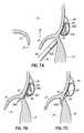
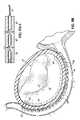
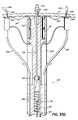
- Fig. Hillustrates the cardiac anatomy, highlighting the relative position of the coronary sinus (CS) 46 running behind the posterior leaflet 24 of the mitral valve 20 .
- Fig. Iis an illustration of the same anatomy but schematically shows a cinching device 48 which is placed within the CS 46 using a catheter system 50 , with distal, mid, and proximal anchors 52 a , 52 b , 52 c within the lumen of the CS 46 to allow plication of the annulus 40 via the CS 46 .
- these anchors 52 a - care cinched together, i.e., the distance between them is shortened by pulling a flexible tensile member 54 such as a cable or suture with the intent being to shorten the valve annulus 40 and pull the posterior leaflet 24 closer to the anterior leaflet 22 in a manner similar to an annuloplasty procedure.
- a flexible tensile member 54such as a cable or suture
- the anchors 52 a - care prone to tear the tissue during the cinching procedure, and the effect on the mitral annulus may be reduced by the position of the coronary sinus up more towards the left atrium rather than directly over the mitral annulus itself.
- Other minimally invasive techniqueshave been proposed and/or developed but have various drawbacks related to such factors as effectiveness and/or cases and accuracy of catheter-based implementation.
- the inventionprovides a method of modifying an annulus of a heart valve in a first general aspect.
- the annuluslies generally below the coronary sinus at least at one location.
- the methodcomprises fastening the coronary sinus to the annulus to bring the annulus closer to the coronary sinus at least at the one location, and then reducing regurgitation by modifying the annulus.
- the annulusmay be modified by shortening the circumferential length (i.e., the arc length) of the annulus or changing the shape or other physical characteristic of the annulus.
- Fastening the coronary sinuscan further comprise inserting a first guide element into the coronary sinus, directing a second guide element into the left ventricle so it lies under and/or adjacent to the annulus, securing the first and second guide elements together, and applying a fastener between the annulus and the coronary sinus.
- the guide elementsmay be removed after applying the fastener, and therefore act as a temporary anchor for the fastener delivery device and/or the tissue to be secured. Alternatively, the guide elements, or portions thereof, may be left in place.
- the guide elementsmay comprise mechanical fasteners or other types of fasteners such as magnets (i.e., magnetic elements), or combinations thereof.
- One guide element of the inventioncomprises first and second spaced apart magnets on the distal support portion of a catheter. Repelling poles of the magnets face each other to create a circumferential virtual pole emanating around the gap formed between the spaced apart magnets. Securing the first and second guide elements together can further comprise magnetically attracting the first and second guide elements together.
- the same catheter devicemay be used to direct the second guide element and apply the fastener.
- the methodcan include applying a second fastener to the annulus, coupling the first and second fasteners together, and reducing the distance between the first and second fasteners to reduce the circumference of the annulus.
- applying the first and second fastenerscan occur through the same catheter device.
- the methodcan involve serially applying the first and second fasteners through one lumen in a catheter device or, as another example, applying the first and second fasteners through different lumens of the same catheter device.
- at least one flexible tensile memberis used to couple the first and second fasteners together and the flexible tensile member is tensioned to reduce the distance between the first and second fasteners.
- Shortening the circumferential length of the annuluscan further comprise fastening a flexible fabric to the annulus and shortening the circumferential length of the flexible fabric.
- a method of modifying an annulus of a heart valvecomprises applying first and second fasteners on opposite sides of the annulus through at least one catheter thereby holding heart tissue between the first and second fasteners, applying third and fourth fasteners on opposite sides of the annulus through at least one catheter thereby holding heart tissue between the third and fourth fasteners.
- different catheters or different catheter portionsmay be used to apply the different fasteners or the same catheter may be used.
- the first and second fastenersare coupled and the third and fourth fasteners are coupled using at least one flexible tensile member. The distance between adjacent ones of at least two of the first, second, third and fourth fasteners is reduced by applying tension to the flexible tensile member thereby modifying the annulus.
- the first, second, third, and fourth fastenerscan include at least one magnet and/or at least one mechanical fastening element, such as a mechanical element configured to penetrate and engage with tissue.
- the methodcan include using at least one magnet delivered through a catheter to guide at least one of the fasteners into position.
- the guiding magnetmay be removed after guiding the fastener or fasteners into position.
- the fastener or fastenersmay be delivered through the guiding magnet.
- a heart valve annulusis modified by delivering a first fastener through a catheter into the coronary sinus, and delivering a second fastener through a catheter to at least one of two locations, the two locations being 1) generally above the annulus in the left atrium, and 2) generally below the annulus in the left ventricle.
- the fastenersare secured to the annulus and the distance between the first and second fasteners is reduced to thereby modify the annulus with the respectively delivered fasteners.
- a flexible tensile memberis connected between the fasteners, and the distance between the fasteners is reduced by tensioning the flexible tensile member to modify the annulus.
- the flexible tensile membermay be locked into position with respect to the fasteners by applying a crimp member or other locking element, which may or may not be part of a fastener, to the flexible tensile member.
- the fastenersare held in spaced apart positions while securing the fasteners to heart tissue at the two locations.
- the fastenersare biased toward each other to reduce the distance between adjacent fasteners and modify the annulus with the respectively delivered fasteners. Biasing the fasteners can further comprise magnetically attracting adjacent fasteners toward one another or, as another example, spring biasing adjacent fasteners toward one another.
- pressurized airmay be used to hold the fasteners in the spaced apart positions prior to biasing the fasteners together.
- radio frequency energy or any other suitable methodis used to form an aperture in the heart tissue in order to apply the fastener(s) through the tissue.
- the inventionfurther provides a system for modifying an annulus of a heart valve comprising a first catheter, a first magnet coupled with the first catheter in such a manner that the first catheter is operative to deliver the first magnet adjacent to the annulus.
- the systemfurther includes a second catheter and a second magnet coupled with the second catheter in such a manner that the second catheter is operative to deliver the second magnet adjacent to the annulus.
- a fastener delivery portionmay be operatively associated with the first catheter. The fastener delivery portion may be coupled at predetermined angle relative to an axis of magnetic attraction between the first and second magnets.
- the fastener delivery portioncan be movable relative to the first and second magnets so as to enable delivery of a fastener to a desired position.
- the systemcan further comprise a plurality of fastener delivery portions configured to deliver respective fasteners at spaced apart locations along the annulus.
- the plurality of fastenersmay be coupled together with at least one flexible tensile member such that the flexible tensile member is capable of drawing the fasteners together and thereby modifying the annulus.
- a catheter system for modifying an annulus of a heart valvecomprises a catheter having at least one lumen and first and second fasteners coupled together by an elongate flexible member such that the first fastener is movable along the elongate flexible member to a position closer to the second fastener.
- An actuation deviceis coupled in a releasable manner to the elongate flexible member and adapted to pull the elongate flexible member to thereby reduce the distance between the first and second fasteners.
- a couplingsecures the elongate flexible member in a locked position relative to the first and second fasteners.
- the first and second fastenerscan further comprise magnets and/or mechanical fasteners, such as fasteners having projections configured to penetrate heart tissue.
- the couplingfurther can further comprise a crimpable or other type of locking member.
- the first and second fastenersmay be further coupled together by a length adjustable member configured to allow the distance between the first and second fasteners to be shortened as the actuation mechanism pulls the flexible tensile member.
- the length adjustable membercan include first and second telescoping portions coupled together or, as another example, a generally accordion-shaped section.
- a catheter system for modifying an annulus of a heart valvecomprises a catheter having at least one lumen and first and second fasteners coupled together by a flexible tensile member such that the first fastener is movable along the flexible tensile member relative to the second fastener.
- a first fastener delivery portionis coupled with the catheter and delivers the first fastener into a first position proximate the annulus.
- a second fastener delivery portionis coupled with the catheter and moves with respect to the first fastener delivery portion. The second fastener delivery portion delivers the second fastener into a second position proximate the annulus and spaced from the first position.
- This systemcan further include a third fastener coupled to the flexible tensile member, and a third fastener delivery portion coupled with the catheter and capable of delivering the third fastener into a third position proximate the annulus and spaced from the first and second positions.
- the systemcan also include first and second fastener drive members coupled respectively with the first and second fastener delivery portions, and being selectively movable to drive the first and second fasteners into the tissue proximate the annulus.
- the systems of this inventioncan include fastener delivery portions comprising at least one spring and drive member each located, for example, at the distal end of a catheter device.
- Such fastener delivery portionscan force the fastener(s) into tissue proximate the annulus.
- Catheters used in the inventioncan include a magnet at the distal end for coupling with another magnet located proximate the annulus thereby stabilizing the catheter during delivery of the fastener(s).
- a lock membermay be secured to the flexible tensile member and used to selectively prevent relative movement between the delivered fasteners.
- a catheter system for modifying an annulus of a heart valveincludes a catheter having at least one lumen and first and second fasteners coupled together by a flexible tensile member and adapted to be secured to heart tissue proximate the annulus.
- a rodis movable between a compact state within the lumen and an expanded state outside of the lumen.
- the first and second fastenersare further coupled to the rod such that the first fastener is movable along the rod relative to the second fastener by applying tension to the flexible tensile member.
- the rodmay be generally C-shaped in the expanded state so as to follow the annulus.
- a third fastenermay be coupled for movement along the rod and adapted to be secured to heart tissue proximate the annulus.
- a second flexible tensile membercan be secured to the third fastener.
- the third fastenermay then be moved along the rod relative to the second fastener by applying tension to the second flexible tensile member.
- a magnetcan be connected to the rod and adapted to magnetically couple with a magnet in the coronary sinus for stabilizing the position of the rod as the fasteners are secured to the heart tissue.
- Another catheter system for modifying an annulus of a heart valvegenerally comprises a catheter having at least one lumen and first and second fasteners adapted to be secured to heart tissue proximate the annulus. At least one flexible tensile member couples the first and second fasteners together.
- a locking device activated by way of a catheter to fix the fastener positionsis provided.
- a locking element delivery deviceis deployable through a catheter, which may be the same catheter as a fastener delivery catheter, or a different catheter.
- the locking elementcan be a crimp and a compression applying mechanism deployed from the catheter can be configured to compress the crimp onto the flexible tensile member after the fasteners are pulled toward one another with the flexible tensile member to modify the annulus.
- locking elementsmay, for example, include spring elements or other biased elements which are held in an open position and then released into a closed or locked position onto one or more flexible tensile members. Any locking element which is selectively lockable onto a flexible tensile member may be used as appropriate for the application.
- a flexible tensile member releasing deviceis provided which releases the flexible tensile member from the catheter system is also provided. This may involve a mechanical disconnection mechanism, such as threads or other connectors, or a cutting mechanism associated which cuts the flexible tensile member after locking takes place, such as mentioned above.
- a third fasteneris adapted to be secured to the heart tissue, and separate flexible tensile members may be connected with each of the fasteners and threaded through the locking element, such as a crimp.
- the term “flexible tensile members”, as used herein,will apply to separate portions of a single element, such as a suture strand, wire, cable or other solid or hollow elongate structure which may be looped back on itself and locked in place, and it will also apply to separate elements altogether.
- Another catheter system for modifying an annulus of a heart valvecomprises first, second and third fasteners adapted to be secured to heart tissue proximate the annulus.
- First, second and third flexible tensile membersare respectively connectable to the first, second and third fasteners.
- a generally V-shaped valve support memberis provided having a pair of legs movable between a compact state suitable for carrying the valve support member within a catheter and an expanded state in which the legs are more separated.
- a free end of each legincludes respective first and second eyelets receiving the first and second flexible tensile members and an apex between the pair of legs including a third eyelet receiving the third flexible tensile member.
- First, second and third crimp membersmay be provided for respectively securing the first, second and third flexible tensile members with respect to the first, second and third eyelets after at least one of the flexible tensile members is pulled tight to modify the shape of the annulus.
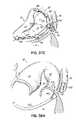
- Fig. Ais a cutaway of the left side of the heart showing the internal muscular and valve structure.
- Fig. Bis a top view showing the normal positions of a mitral valve and adjacent aortic valve.
- Fig. Cis a top view similar to Fig. B but illustrating the mitral valve in a prolapsed condition in which the posterior leaflet is separated from the anterior leaflet.
- Fig. Dis an elevational view illustrating a conventional annuloplasty ring.
- Fig. Eis a top view similar to Fig. B, but illustrating the attachment of the annuloplasty ring to the mitral valve annulus.
- Fig. Fis a top view of the mitral valve illustrating an Alfieri stitch technique for reducing the gap between the posterior and anterior leaflets.
- Fig. Gis a top view of the mitral valve illustrating another suturing technique which has been used to close the gap between the posterior and anterior leaflets.
- Fig. His a cross sectional view of the heart anatomy illustrating the coronary sinus (CS) running behind the posterior leaflet of the mitral valve.
- CScoronary sinus
- Fig. Iis a cross sectional view of the heart anatomy similar to Fig. H, but illustrating a technique for inserting anchors into the CS using a catheter based system.
- FIG. 1Ais a cross sectional view of the heart anatomy similar to Fig. I but illustrating an improved catheter based procedure for inserting anchors into the CS and correcting for mitral valve insufficiency according to the invention.
- FIG. 1Bis an enlarged view of the connector placed in accordance with the invention through the CS and the annulus tissue of the mitral valve.
- FIG. 2Ais a cross sectional view of the mitral valve illustrating the posterior and anterior leaflets and the relative position of the CS with respect to the valve annulus.
- FIG. 2Bis a view similar to FIG. 2A and illustrating the effect of cinching or pulling the CS toward the mitral valve opening at a location which is above the level of the valve annulus.
- FIG. 2Cis a view similar to FIG. 2B , but illustrating the placement of a fastener in accordance with the invention to bring the level of the CS closer to the annulus before cinching.
- FIG. 3is a cross sectional view of the heart anatomy, on the left side of the heart, illustrating a catheter based system according to the invention.
- FIGS. 3A-3Dillustrate a progression of steps in a catheter based method for correcting a mitral valve insufficiency in accordance with the invention.
- FIGS. 4 and 5illustrate a cross section of the mitral valve in which anchors have been daisy chained together and then cinched to close the gap between the leaflets of the valve.
- FIGS. 6 A- 6 E- 1illustrate a cross section of the heart anatomy through the CS and illustrating a pair of catheter devices being used to successively apply fasteners in a daisy chained fashion and both cinch and lock the fasteners in place.
- FIGS. 6 F and 6 F- 1illustrate the final locked positions of the fasteners, flexible tensile member and locking member placed via catheters.
- FIGS. 7A-7Gare enlarged cross sectional views of the mitral valve at the valve annulus taken generally along line 7 - 7 of FIG. 6A and showing the placement of a fastener from the CS downwardly through the valve annulus to the underside or left ventricle side of the valve.
- FIGS. 8A and 8Billustrate cross sectional views, respectively, through the CS and illustrating the use of a pair of magnets in the CS for magnetically guiding and locking up with a magnet on an anchor delivery catheter.
- FIG. 8Cis an enlarged view of the various magnets and their magnetic fields.
- FIG. 9is a cross sectional view of the heart anatomy through the CS, and illustrating the use of electromagnets in a catheter device.
- FIG. 10is a cross sectional view of the heart anatomy through the CS and illustrating the successive positioning of a catheter device relative to another catheter device in the CS through the use of magnets.
- FIGS. 11A and 11Billustrate cross sectional views of the heart anatomy through the CS and respectively illustrating nonactivated and activated positions of a series of magnetic fasteners used for correcting a mitral valve insufficiency.
- FIGS. 11A-1 and 11 B- 1respectively illustrate enlarged views of the magnetic fastener system in its nonactivated and activated states.
- FIG. 11Cis a cross sectional view through the mitral valve and CS illustrating the final activated position of the fastener system placed in accordance with FIGS. 11A and 11B .
- FIGS. 12A and 12Billustrate an alternative in which the magnetic fasteners are placed respectively in the CS and in the left atrium.
- FIGS. 13A and 13Bare cross sections of the heart anatomy through the CS and illustrating an additional magnetic fastener placed below the annulus in left ventricle to assist with reducing the mitral valve insufficiency.
- FIGS. 14A and 14Bare cross sections through the CS and mitral valve and illustrating another alternative magnetic fastening system.
- FIG. 14Cis similar to FIG. 14B , but illustrates a magnetic fastener with additional mechanical fastening elements in the form of projections which engage and penetrate tissue proximate the valve annulus.
- FIGS. 14D and 14Eare perspective views illustrating the magnetic fastening elements with mechanical tissue engaging projections.
- FIGS. 15A-15Care cross sections through the CS and mitral valve illustrating an alternative fastener delivery mechanism in which a fastener is delivered through a catheter and also through magnetic guiding elements.
- FIGS. 15D and 15Eare cross sections similar to FIG. 15A , but illustrating a series of fasteners delivered through magnetic guiding elements and daisy chained together using a flexible tensile member.
- FIGS. 16A-16Care cross sectional views similar to FIGS. 15A-15C , but illustrating the use of magnetic guiding elements which have separable portions.
- FIGS. 16A-1 and 16 A- 2are perspective views of the magnetic guiding elements respectively shown in nonseparated and separated positions.
- FIGS. 16D and 16Eare similar to FIGS. 15D and 15E , and illustrate the daisy chained connection of the fasteners with the magnetic guiding elements removed.
- FIG. 17is a perspective view showing a fastener delivery mechanism on a catheter which includes a magnetic guiding element magnetically coupled to a second magnetic guiding element of a second catheter.
- FIGS. 18A-18Crespectively illustrate cross sectional views of the heart anatomy through the CS and the mitral valve and the placement of an alternative catheter delivered fastening system.
- FIG. 19Ais a cross sectional view of the heart anatomy through the CS and the placement of another alternative catheter delivered fastening system.
- FIGS. 19B and 19Cillustrate the daisy chained fasteners of FIG. 19A respectively before and after cinching of the fasteners to shorten the valve annulus.
- FIGS. 20A and 20Billustrate a cross sectional view of tissue receiving fasteners formed from shape memory alloy both before and after activation of the shape memory effect to shorten the overall length of the tissue engaged with the fasteners.
- FIG. 21Ais a cross sectional view of the heart anatomy through the CS and illustrating the use of a catheter to delivery a series of fasteners in the form of tissue penetrating fasteners separated by pledgets along a flexible tensile member.
- FIGS. 21B-21Drespectively illustrate enlarged views of the fastener delivery system shown in FIG. 21A as well as the final cinching thereof.
- FIG. 22illustrates an alternative system to FIGS. 21A-21D in which a secondary cinching mechanism is provided in the form of a second flexible tensile member.
- FIGS. 23A-23Eillustrate respective cross sections of the heart anatomy through the CS and the use of another alternative catheter based system for serially delivering fasteners coupled with a flexible tensile member used to cinch valve tissue and correct a mitral valve insufficiency.
- FIGS. 24A-24Care respective cross sections through the heart anatomy including the CS above the mitral valve and illustrating another alternative catheter based fastener system.
- FIGS. 25A-25Dillustrate an enlarged cross section of the catheter based system of FIGS. 24A-24C , and showing the cinching and locking thereof.
- FIGS. 26A-26Billustrate another alternative cinching and locking system for a catheter based fastener system similar to FIGS. 25A-25D .
- FIG. 26Cis a cross section taken along line 26 C- 26 C of FIG. 26A .
- FIGS. 27A and 27Billustrate yet another alternative cinching and locking mechanism associated with a catheter based fastener system similar to FIGS. 26A and 26B .
- FIGS. 28A and 28Bare respective cross sections similar to FIGS. 27A and 27B , but illustrating another alternative fastening system.
- FIGS. 29A and 29Billustrate respective cross sections of yet another catheter based fastening system.
- FIG. 30illustrates a cross section of yet another catheter based fastener system.
- FIG. 31Ais a cross section taken along line 31 A- 31 A of FIG. 30 .
- FIG. 31Bis a cross section taken along line 31 B- 31 B of FIG. 30 .
- FIGS. 32A and 32Billustrate another alternative fastening system in its nonactivated and activated states.
- FIG. 32Cis a cross section taken along line 32 C- 32 C of FIG. 32A .
- FIG. 33is a cross section of another alternative fastening system.
- FIGS. 33A and 33Bare enlarged cross sectional views of portions of FIG. 33 respectively shown in nonactivated and activated states.
- FIGS. 34A-34Iare respective cross sections of the heart anatomy successively showing the use of another alternative catheter based fastening system.
- FIG. 35Ais a cross section taken through the CS and illustrating a perspective view of another alternative catheter based fastener delivery device.
- FIGS. 35B-35Eare respective cross sections of the fastener delivery device shown in FIG. 35A and used to deliver multiple fasteners coupled to a flexible tensile member.
- FIG. 35Fis a cross sectional view of the fastening system delivered, cinched and locked to shorten the length of tissue engaged with the system.
- FIG. 36is a perspective view of the distal end of another alternative catheter based fastener delivery system.
- FIG. 37Ais a fragmented view of the distal end of another catheter based system for delivering a fastener and valve support member of the invention.
- FIGS. 37B and 37Crespectively illustrate the deployed valve support and fastener system on the mitral valve.
- FIGS. 38A-38Irespectively illustrate cross sections of the mitral valve and CS and the progression of using another catheter based fastener delivery system.
- FIGS. 39A and 39Brespectively illustrate cross sections of the distal end of a crimping and cutting device which may be used with various catheter based systems of this invention.
- FIGS. 40A-40Drespectively illustrate cross sections through the heart anatomy including the mitral valve and CS, and illustrating another alternative catheter based fastener delivery system.
- FIGS. 41A-41Cillustrate another catheter based fastener delivery system.
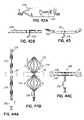
- FIG. 42Aillustrates an elevational view of one exemplary fastener usable in the systems described herein.
- FIG. 42Bis a cross sectional view taken along line 42 B- 42 B of FIG. 42A .
- FIG. 43is a side elevational view of another alternative fastener having a curved shape.
- FIGS. 44A-44Crespectively illustrate the use of another alternative fastener suitable for the systems of the present invention.
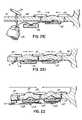
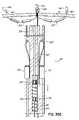
- FIGS. 1A and 1Billustrate an improved catheter delivered fastener system 50 ′ which involves placing a permanent fastener or anchor 60 from the CS 46 through the wall of the left atrium 12 proximate annulus 40 for anchoring purposes. This improvement may be applied to the prior cinching method illustrated in Fig. I discussed above.
- the fastener 60may be deployed and anchored in various manners, including those discussed further below.
- FIGS. 2A and 2Billustrate the anatomical relationship between the CS 46 and the mitral annulus 40 .
- the CS 46can be noncoplanar with the mitral annulus 40 , causing CS based cinching approaches to the inefficient to effectively modify the shape of the annulus 40 .
- the CS 46extends above the mitral annulus 40 along the left atrial wall and, instead of pulling the annulus 40 toward the valve opening or gap 32 , the left atrial wall is instead pulled inwardly as shown in FIG. 2B .
- Thiscauses more of a restriction of the atrium 12 above the valve 20 , rather than a reduction of the annulus 40 itself and, therefore, prevents a complete correction of the valve insufficiency in this case.
- a fastener or anchor 62extends from the CS 46 into the left ventricle side of the annulus 40 .
- a CS cinching devicecan more efficiently and effectively reduce the mitral annulus 40 . That is, when cinched toward the valve opening or gap 32 , the cinching device, which is more in line with the valve annulus 40 , can better pull the posterior leaflet 24 toward the anterior leaflet 22 thereby closing the gap 32 between the leaflets.
- a pair of magnetically attractive catheters 64 , 66can be used in concert with each other using the CS 46 as an approximate guide to locate and position the tip of another catheter or catheter portion at the mitral annulus 40 . More specifically, as one example, one catheter 66 includes both a magnetic guiding portion 66 a and an anchor delivery portion 66 b positioned in a predetermined manner, such as at a predetermined acute angle relative to the magnetic portion 66 a . Another catheter 64 is placed in the CS 46 and includes a magnetic guiding portion 64 a .
- the two magnetic guiding portions 64 a , 66 amagnetically couple with one another to lock up the position of the anchor delivery catheter portion 66 b at a predetermined angle which will properly deliver a fastener or anchor 68 into a desired portion of the tissue.
- the magnetically locked catheters 64 , 66can deliver a first loop type anchor or fastener 68 through the valve annulus 40 on a skewed or otherwise known trajectory from the axis of magnetic attraction, such that the loop type anchor or fastener 68 is accurately placed, for example, through the annulus 40 from the left ventricle side to the left atrium side of the mitral valve 20 .
- FIG. 3Athe magnetically locked catheters 64 , 66 can deliver a first loop type anchor or fastener 68 through the valve annulus 40 on a skewed or otherwise known trajectory from the axis of magnetic attraction, such that the loop type anchor or fastener 68 is accurately placed, for example, through the annulus 40 from the left ventricle side to the left at
- the CS catheter 64can be translated to a different position within the CS 46 causing the magnetic tip 66 a of the left ventricle catheter 66 to follow along the annulus 40 where subsequent loop type anchors or fasteners 68 may be placed in a similar fashion to the first applied anchor or fastener 68 .
- FIG. 3Cillustrates that a loop type fastener or anchor 68 may capture a T-bar type anchor or fastener 70 passing from the CS 46 through the left atrial wall using a catheter delivery system 72 guided within the CS 46 .
- fasteners 68are therefore placed from the left ventricle 14 into the left atrium 12
- additional connecting fasteners 70are placed from the CS 46 into the left atrium 12 for engagement with the other fasteners 68 .
- multiple loop and T-bar anchors or fasteners 68 , 70may be cinched together with a flexible tensile member 74 similar to a drawstring-type configuration, resulting in alignment of the CS 46 and the annulus 40 into a more coplanar relationship at several locations.
- the cinching or drawstring actiontherefore closes the gap 32 between the posterior leaflet 24 and the anterior leaflet 22 in a more even and effective manner.
- FIG. 4illustrates magnetically attractive catheter portions 64 a , 66 a respectively in the CS 46 and under the mitral annulus 40 used to deliver a series of anchors or fasteners 76 with a T-bar shape from the left ventricle side of the mitral valve 20 to the left atrium side of the mitral valve 20 .
- the T-bar shaped anchor fasteners 76are delivered in a daisy chained fashion from catheter portion 66 b such that a second catheter 78 may be used to cinch a drawstring or flexible tensile member 80 to shorten or reduce the valve annulus 40 .
- FIG. 4illustrates magnetically attractive catheter portions 64 a , 66 a respectively in the CS 46 and under the mitral annulus 40 used to deliver a series of anchors or fasteners 76 with a T-bar shape from the left ventricle side of the mitral valve 20 to the left atrium side of the mitral valve 20 .
- the T-bar shaped anchor fasteners 76are delivered
- the anchors or fasteners 76may be cinched together using the drawstring or flexible tensile member 80 within catheter 78 to pull the posterior leaflet 24 toward the anterior leaflet 22 .
- the flexible tensile member 80is then locked in place or otherwise secured to retain the fasteners 76 in their new positions, such as in one of the manners described below.
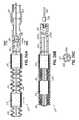
- FIGS. 6A-6Frespectively illustrate catheters 82 , 84 being placed into the heart 10 through the aortic valve into the left ventricle 14 and through the CS 46 generally adjacent the valve annulus 40 .
- This top view of the heart 10shows how a first T-bar type anchor or fastener 86 having a tail, forming a flexible tensile member 88 , is loaded into the CS catheter 84 at the proximal end 84 a so that it may be pushed down to the distal tip 84 b to be in position for delivery.
- the position of the left ventrical catheter 82 with a magnetic tip 82 ais also shown generally opposite to the distal tip 84 b of the CS catheter 84 . As shown in FIG.
- a second anchor or fastener 90is delivered in a daisy chain fashion by running an eyelet 90 a on the second anchor 90 over the tail or flexible tensile member 88 associated with the first anchor 86 .
- FIG. 6Cillustrates the second anchor 90 of the daisy chain delivered through the valve annulus 40 at a spaced apart location from the first anchor 86 .
- FIG. 6Dillustrates a third anchor 92 at the annulus 40 similarly delivered along flexible tensile member 88 using an eyelet portion 92 a .
- Anchor 92is threaded through the CS catheter 84 and driven through the tissue generally at the valve annulus 40 .
- FIG. 6Eillustrates a locking member 94 , including a crimp 96 delivered over the daisy chain tail or flexible tensile member 88 within the proximal CS 46 .
- Locking member 94is shaped or otherwise configured to hold its position within the CS 46 .
- FIG. 6E-1illustrates the crimp 96 before crimping onto the flexible tensile member or tail 88 . As shown in FIGS.
- a catheter device 98which may be deployed through a suitable delivery catheter (not shown) may be used to pull the flexible tensile member 88 thereby cinching the assembly and pulling the posterior leaflet 24 toward to the anterior leaflet 22 . Once this cinching is accomplished, the crimp is crimped against the flexible tensile member 88 adjacent to the lock member 94 to keep the assembly at the desired position.
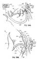
- FIG. 7Aillustrates how magnetically attractive portions 82 a , 84 b of the LV and CS catheters 82 , 84 should be strongly attracted when the gap distance (d 1 ) is relatively short. If this gap distance d 1 is not relatively short, then other methods of increasing the lock up force may be necessary as further described herein below.
- FIGS. 7B and 7Cillustrate how a T-bar type anchor or fastener 86 would be pushed from an opening 84 c in the CS catheter through the tissue from the CS 46 into the left ventricle 14 until it is fully deployed across the tissue.
- FIG. 7Dillustrates a larger gap d 2 , through which two magnetic portions 82 a , 84 b of the respective LV and CS catheters may magnetically couple, depending on the magnetic attractive forces developed.
- FIGS. 7E and 7Fthe magnetic catheter in the LV 14 has not been illustrated (only for purposes of clarity), such that the delivery of a T-bar type fastener or anchor 86 may be shown in its fully deployed state across the tissue. As shown in FIG.
- the T-bar portion or transverse portion 86 b of the fastener 86self-rotates in order to fit snugly along the annulus 40 under the posterior leaflet 24 .
- FIG. 7Gthe relative position of the CS 46 to the annulus 40 is improved after cinching of the anchor 86 plicates the tissue between the annulus 40 and the CS 46 as previously described.
- FIGS. 8A-8Cillustrate that multiple magnets 102 a , 102 b may be used in the CS, such as on a CS catheter 102 , to attract an opposite magnet pole at the tip 100 a of the LV catheter 100 .
- Thisallows the LV catheter 100 to be steered in three axes to deliver a fastener through a second catheter portion 100 b into the annulus 40 .
- multiple magnetsmay also or alternatively be used in the LV 14 and/or in the LA for steering purposes and/or additional magnetic force.
- 8Cillustrates in detail how a pair of magnets 102 a , 102 b in the CS 46 mounted such that like poles are facing each other results in a 360° magnetic field which attracts the opposite pole of a magnetic catheter tip 100 a within the LV 14 . This can eliminate the need to rotationally orient the CS catheter 102 so that its pole is facing an opposite pole in the LV 14 .
- FIG. 9illustrates the use of electromagnets 104 in a CS catheter 106 which may be used in conjunction with or as replacements for permanent magnets as described in the above embodiments.
- one element which generates magnetic forcesmay be used in conjunction with another element which is magnetically attracted to the magnetic force generating element, but not necessarily a magnetic force generating element itself.
- an electromagnet or permanent magnetmay be positioned on one side of the tissue to be anchored, and another element formed from ferrous metal may be positioned on the opposite side of the tissue for magnetic coupling purposes while a fastener or anchor is driven into the tissue.
- FIG. 10illustrates a CS catheter 108 configured with multiple opposite pole magnetic pairs 110 , 112 along its length and a steerable LV catheter that may be directed to each discrete pair of magnets 110 , 112 to delivery anchors or fasteners (not shown), such as in one of the manners previously described.
- a CS catheter 116may be configured with multiple discrete magnets 118 along its length, wherein the poles of the magnets 118 are arranged such that they are magnetically attracted to each other, yet kept apart by a restraining force, such as pressurized air directed to a bladder-like structure 120 between the magnets 118 .
- a restraining forcesuch as pressurized air directed to a bladder-like structure 120 between the magnets 118 .
- the magnets 118are being used as fasteners to fasten or trap tissue therebetween.
- a similar catheter 122delivers magnets 124 on an opposite side of the tissue, such as within the LV 14 .
- each strip of magnets 118 , 124has opposing poles along its length and thereby plicates the tissue by removing a restraining force between the magnets 118 in the CS 46 , thereby allowing the attracted magnets 118 to move toward each other and plicate the annulus tissue therebetween.
- the magnets 124 in the LV catheter 122may be configured in the same manner as magnets 118 .
- FIGS. 12A and 12Billustrate respective strips of magnets 118 , 124 , as described in connection with FIGS. 11A-11C in the CS 46 and the LA 12 instead of the LV 14 .
- the two strips of respective magnets 118 , 124align with each other such that the magnets 118 , 124 are anchored to each other across the left atrial wall. In this case, once again, the stronger atrial wall is used as the anchoring tissue, as opposed to the CS tissue only.
- FIGS. 13A and 13Billustrate strips of magnets 118 , 124 in the CS 46 and LA 12 as discussed previously.
- cinching via the CS 46alone may not have sufficiently precise pull on the mitral annulus 40 since these two anatomical structures typically do not lie at the same level.
- Even the two strips of magnets 118 , 124 shown in FIG. 12Bare only coupled across the left atrial wall, and this may not be in line with the annulus 40 at all locations. Therefore, an additional magnet 126 shown in FIGS. 13A and 13B , fixed to a metal or otherwise substantially rigid curved bar 128 , is placed under the mitral valve 20 in the LV 14 , such that magnet 126 locks up with the strip of magnets 118 in the CS 46 . This pulls the exterior annulus 40 toward the CS 46 and establishes a more coplanar relationship.
- FIG. 14Aillustrates a modification of the strip of magnets 124 positioned in the LA 12 such that there is an extension magnet 130 which is positioned at the midpoint of the strip of magnets 124 .
- This extension magnet 130extends down to the mitral valve annulus 40 bridging the gap between the CS 46 and the valve annulus 40 .
- Thismay pull a magnet 132 and curved support bar 134 under the valve 20 tighter to the CS 46 , as shown in FIG. 14B .
- magnet 132 and support bar 134are similar to magnet 126 and support bar 128 , except that bar 134 has a fabric covering 136 as may be desired for tissue ingrowth purposes.
- FIGS. 14C-14Eillustrate the use of additional mechanical fasteners such as projections 138 on one or more of the magnets 132 used in the embodiments described above. This can apply additional traction or fastening to the tissue than could otherwise be supplied by the use of magnets alone.
- FIGS. 15A-15Ecomprise a series of illustrations showing another alternative catheter based fastener delivery system.
- this systemutilizes magnets 142 , 144 which have orifices 142 a , 144 a through which the fastener 140 is delivered such that more precise placement of the fastener 140 may be obtained in certain instances while also using a magnetic lock up force for more positively driving the anchor or fastener 140 .
- magnet 144will be coupled to a catheter (not shown) for positioning within the CS 46 .
- Magnet 142may be releasably coupled to a steerable catheter 146 .
- a flexible tensile member 148 and crimps 150may be used to cinch and lock the fasteners 140 together thereby pulling the posterior leaflet 24 toward the anterior leaflet 22 and closing a gap 32 in the valve 20 .
- FIGS. 16A-16Eillustrate a system which is the same as the system shown in FIGS. 15A-15E , except that the magnets 142 ′, 144 ′ are formed of separable portions, such as halves 142 a , 142 b , 144 a , 144 b , so that the magnets 142 ′, 144 ′ may be removed after the fasteners 140 ′ have been properly delivered.
- the magnets 142 ′, 144 ′are formed of separable portions, such as halves 142 a , 142 b , 144 a , 144 b , so that the magnets 142 ′, 144 ′ may be removed after the fasteners 140 ′ have been properly delivered.
- the anchors or fasteners 140 ′themselves have portions 140 a , 140 b which retain the fasteners 140 ′ in place across the tissue proximate the annulus 40 , and portions 140 b accept a flexible tensile member 148 and crimps 150 for cinching and locking purposes as shown in FIGS. 16D and 16E generally in the manner or manners described herein.
- the separable magnet portions 142 a , 142 b and 144 a , 144 bmay be coupled to suitable catheter devices allowing their release from fasteners 140 ′ and withdrawal from the patient.
- FIG. 17Aillustrates an alternative fastener delivery system 160 using magnetic guidance in which the fastener 140 ′ is not delivered through the magnets 162 , 164 , but is delivered adjacent to the magnets 162 , 164 in a fastener driving portion 166 of a catheter 168 .
- Thisis another manner of using magnetic guidance and temporary lock up without the necessity of leaving the magnets 162 , 164 in place after completion of the procedure.
- FIGS. 18A-18Cillustrate a more conventional annuloplasty that may be accomplished using magnetic guidance and lock up in a temporary manner to facilitate fastener placement and driving. More specifically, a magnetic strip 170 is placed into the CS 46 using a catheter 172 . A second magnetic strip 174 with a fabric covering 176 is placed in the left atrium 12 also via a catheter 178 . Fasteners 180 are placed into the fabric 176 on the strip 174 in the left atrium 12 from the undersurface of the mitral valve 20 again using a catheter 82 . Likewise, fasteners 180 are driven through the CS 46 and left atrium wall into the fabric 176 in a manner similar to that described with respect to, for example, FIGS.
- FIGS. 7D-7FThe magnetic strips 170 , 174 are removed from the fabric covering 176 and from the CS 46 and the fabric 176 is then drawstringed or cinched with a suitable flexible tensile member 184 coupled therewith to produce annuloplasty or pulling of the posterior leaflet 24 toward the anterior leaflet 22 to eliminate or reduce a gap 32 in the mitral valve 20 .
- FIGS. 19A-19Cillustrate one alternative to a T-bar configuration of fasteners as previously described.
- fasteners 190 in the form of anchor buttons 190 aare placed below the mitral valve 20 along the annulus 40 using catheters 192 , 194 with magnetic guidance and lock up as previously described.
- another catheteris used in the left atrium to deliver buttons 190 b which couple with buttons 190 a .
- Buttons 190 aare further coupled to a flexible tensile member 196 which may be secured with crimps 200 (one shown in FIG. 19C ) as previously described. This compresses the mitral tissue between respective tissue engaging portions of the buttons 190 a , 190 b .
- the buttons 190 a , 190 bare drawstringed or cinched from below using flexible tensile member 196 threaded through respective eyelet portions 198 of each button 190 a.
- FIGS. 20A and 20Billustrate another way to plicate the annulus 40 by using memory alloy staples 202 driven into the tissue along the annulus 40 .
- the staples 202shorten and plicate the tissue ( FIG. 208 ) to shorten the annulus 40 of the mitral valve 20 to pull the posterior leaflet toward the anterior leaflet as generally described above.
- FIGS. 21A-21Dillustrate the placement of fasteners 210 on the left atrial side of the mitral valve 20 , daisy chained to pledgets or fasteners 212 in the form of tissue trapping load spreading members underneath the annulus 40 . These fasteners 210 , 212 are coupled together by a flexible tensile member 214 or drawstring, in this case.
- FIGS. 21A-21Cillustrate a catheter 216 which delivers fasteners 210 , 212 in a serial fashion along flexible tensile member 214 such that fasteners 210 are driven through the tissue and fasteners or pledgets 212 are released between each fastener 210 .
- the series of fasteners 210 , 212is then drawn together using the drawstring or flexible tensile member 214 as shown in FIG. 21D . This shortens the distance between each of the fasteners 210 , 212 and the entire structure with elements above and below the annulus 40 . The tissue becomes trapped between the fasteners 210 , 212 spreading loads over larger areas and reducing tear out risks.
- FIG. 22illustrates a modified version of the system illustrated in FIGS. 21A-21D .
- a second drawstring 218 coupled to eyelets 220 each of the pledgets 212 ′may be pulled for a secondary shortening operation which further reduces the annulus 40 , as necessary.
- FIGS. 23A-23Eillustrate an alternative embodiment which is similar to FIGS. 21A-21D , except that the pledgets 212 ′′ have a pair of holes 222 , 224 through which the flexible tensile member 214 or drawstring is threaded, as opposed to an eyelet structure.
- FIGS. 24A-24Cillustrate another embodiment of a catheter based fastener system 230 which employs a series of connected magnets 232 , 234 with one series of magnets 232 lying in the CS 46 lying adjacent to the mitral valve annulus 40 and another series 234 lying in the LV 14 adjacent to the annulus 40 .
- the magnets 232 residing in the CS 46are coupled together by coil springs 236 and by a flexible tensile member 238 , while the magnets 234 in the LV 14 are, in one embodiment, positioned individually in the LV adjacent to magnets in the CS 232 , after release from the LV magnet delivery catheter 240 , as shown in FIG. 24C .
- the array of LV magnets 234is shown in FIG.
- FIG. 24Aadjacent to the CS magnets 232 and connected by a member consisting of a sheath 233 upon which the magnets 234 can slide.
- the array of magnets 234 and the sheath 233are deposited in the LV 14 as the delivery catheter 240 is withdrawn.
- the connecting sheath 233prevents the risk of an embolic accident resulting from a detachment of a single magnet 234 .
- FIG. 24Bthe withdrawal of the LV delivery catheter 240 is shown in more detail.
- the most distal magnet 234is shown attached to the sheath 233 , whereas the next more proximal magnet 234 is still on the shaft of the delivery catheter 240 .
- Each series of magnets 232 , 234is introduced into the positions shown in FIGS.
- a coupling 244is provided and is releasably coupled to a pull wire or cable 246 in the catheter 242 such that the series of magnets 232 may be cinched or drawn together to reduce the circumferential length of the valve annulus 40 .
- the LV magnets 234owing to their attraction to their CS counterparts 232 , are thus pulled together to accomplish plication of the dorsal cusp of the mitral valve 20 adjacent to the annulus 40 . Plication may be better facilitated by features on the surface of the CS magnets 232 which grip the endocardial surface, and promote ultimate tissue ingrowth about the magnets 232 to strengthen the plication.
- FIGS. 25A-25Dthe operation of the coupling 244 , and a release and locking mechanism 250 is shown.
- the initial positionis shown in FIG. 25A in which the magnets 232 are spaced apart by the uncompressed coil springs 236 and the flexible tensile member 238 which is fixed to a coupling element 252 having at least a pair of arms 254 , 256 which releasably grip a complimentary coupling element 258 .
- the complimentary coupling element 258is fixed to a pull wire or cable 260 extending within the delivery catheter 242 .
- the wire or cable 260is pulled as shown in FIG.
- the delivery catheter 242may be pushed to the left as viewed in FIGS. 25B and 25C causing a crimping action of a tube 262 affixed to the most proximal magnet 232 .
- a crimped portion 262 ais then retained within a recessed portion of the coupling element 252 .
- the gripping arms 254 , 256release the complimentary coupling element 258 of the pull wire or cable 260 and the delivery catheter 242 and pull wire or cable 260 may then be removed leaving the locked fastener system 230 in place as shown in FIG. 25D .
- FIGS. 26A-26Cillustrate a fastener system 270 which operates the same as that disclosed in FIGS. 24A-24C and 25 A- 25 D, except that an accordion or bellows type section 272 replaces each coil spring 236 , and internally and externally threaded coupling elements 274 , 276 replace the gripping arms 254 , 256 and coupling element 258 . It will be appreciated that the operation of the system shown in FIGS. 26A-26C is the same as that described in the previous embodiment, except that releasing the coupling element 276 will involve rotating the pull wire or cable 260 to decouple the threaded coupling elements 274 , 276 .
- the recessed portion 252 a of coupling element 252can have an essentially square cross section.
- the crimped portion 262 a of tube 262will thus engage the recessed portion and plastically deform about it to prevent rotation of coupling element 252 with respect to threaded coupling element 276 .
- the coupling element 276 and cablecan thus be effectively unthreaded and released.
- FIGS. 27A and 27Billustrate another alternative catheter based fastener system 280 which is the same as those described with respect to the two previous embodiments, except that the coil springs 236 and accordion shaped bellows sections 272 have been replaced by respective telescoping portions 282 , 284 which carry the magnets 232 fixed therein.
- a releasable coupling 286is formed by a quarter turn bayonet type fastener as opposed to the gripping arms 254 , 256 and element 258 , or the threaded connection 274 , 276 of the two previous embodiments.
- an elastomeric pad 252 bis seated distal to the proximal component of the bayonet connector 286 .
- the pad 252 bWhen the bayonet 286 is engaged in the delivery position, the pad 252 b creates a load on the proximal component which prevents inadvertent release of the system 280 .
- the recessed segment 252 a of the coupling elementcan have a square cross section to prevent rotation of the coupling during disengagement of the bayonet, in a manner similar to the previous embodiment.
- the telescoping portions 282 , 284are flexible and also pivot so that they can conform to the curved shape of the CS 46 .
- the telescoping portions 282 , 284can move together such that detents 288 move from one recess 290 to an adjacent recess 292 of the respective telescoping portions.
- the assemblyis then locked in place as previously described and the bayonet coupling 286 is released for purposes of withdrawing the delivery catheter 242 .
- FIGS. 28A and 28Bare illustrative of another embodiment which is the same as the system shown in FIGS. 27A and 27B , except that the telescoping portions 282 ′, 284 ′ are fabricated of a flexible, elastomeric polymer material to allow the fastener system 280 ′ to conform to the curve of the CS 46 ( FIG. 24C ).
- the fastener system 280 shown in FIGS. 27A and 27Bin which the telescoping elements 284 are fabricated of a relatively more rigid material.
- flexibilityis gained primarily from the length of the detents 290 and 292 , which allow angled positioning of one telescoping element relative to an adjacent one.
- additional flexibility of the fasteneris achieved with the length of the detents 290 and 292 .
- FIGS. 29A and 29Billustrate another system 280 ′′ which is similar to those described in the previous embodiment, except that the telescoping portions 282 ′′, 284 ′′ only have one recess location 290 ′ for initially retaining the relative positions of the telescoping portions 282 ′′, 284 ′′ as shown in FIG. 29A . Also, each telescoping portion 282 ′′, 284 ′′ may have projections 296 which act as mechanical fasteners for engaging tissue within the CS 46 ( FIG. 24C ).
- FIGS. 30 , 31 A and 31 Billustrate another catheter based system 300 for placing magnets adjacent the mitral annulus, such as within the LV 14 (Fig. A).
- a delivery catheter 304receives a plurality of annular magnets 306 .
- Magnets 306may have roughened outer surfaces 306 a for tissue engagement purposes.
- the catheter 304has an outer diameter which is expandable to frictionally retain the magnets 306 at spaced apart locations.
- An internal tube 308may be withdrawn, to the left as illustrated in FIG. 30 , to release the magnets 306 from their frictional engagement with the outer surface of the delivery catheter 304 .
- the delivery catheter 304is shown with a manipulator wire 310 for orienting the direction of the distal tip 312 , and also a core wire 314 for facilitating insertion and removal of the delivery catheter 304 .
- the magnets 306are magnetically coupled to additional magnets (not shown) across the annulus tissue, for example, the internal tube 308 may be withdrawn thereby releasing the delivery catheter 304 from magnets 306 and facilitating its removal by, for example, pulling on the core wire 314 .
- the magnets 306may be coupled together by a thin flexible sheath 316 or other suitable structure.
- FIGS. 32A-32Cillustrate another catheter based system of fasteners comprising a series of magnets 320 held for sliding movement along parallel wires 322 , 324 .
- Additional parallel wires 326 , 328are provided as guide wires to guide the assembly during insertion through a catheter (now shown) to a location adjacent the annulus.
- a suitable mechanism(not shown), is provided for pushing the magnets 320 together along wires 322 , 324 to reduce annulus tissue, for example, with respect to additional movable magnets (not shown) on the opposite side of the tissue.
- the series of magnets 320is locked in the position shown in FIG. 32B , for example.
- magnets 320are coated with a soft polymer 320 a which frictional engages small stop members 322 a , 324 a on wires 322 , 324 to assist with retaining desired positions of the magnets 322 , 324 .
- FIGS. 33 , 33 A and 33 Billustrate another system of fasteners placed via a delivery catheter 242 and including a coupling mechanism 244 and locking mechanism 250 as described above in connection with FIGS. 25A-25D .
- This systemis similar to that described in FIGS. 26A and 26B in that bellows or crumple zones 330 are provided between magnets 232 , as best illustrated in FIGS. 33A and 33B to accommodate movement of adjacent magnets 232 together as they slide along the flexible tensile member 238 while flexible tensile member 238 , which is rigidly attached to the most distal magnet 232 , is pulled to the left as viewed in FIG. 33 .
- the operation of this embodimentis otherwise the same as that described in connection with FIGS. 26A and 26B .
- FIGS. 34A-34Icomprise a series of illustrations of a catheter based system for applying a series of fasteners through tissue generally at the mitral valve annulus and using guidance magnets 102 a ′, 102 b ′ and 100 a ′ (as previously described) in the CS 46 and the LV 14 .
- a left ventrical catheter 340has a portion 342 which uses radio frequency (RF) to effectively drill an initial hole through the tissue and then insert a second larger diameter catheter portion 344 which is steerable, for example, as shown in FIGS. 34B-34D , to make a second hole in the annulus tissue 40 .
- RFradio frequency
- tip 344is movable into a desired hook-like position by a guiding cable 344 a which may be pulled to configure tip 344 into the hooked shape as shown.
- the catheters utilized hereincan include unidirectional or bi-directional steering.
- a steering mechanismmay be positioned within and/or on the devices. Typically, the steering mechanism may include a pull wire 344 a terminating at a flat spring or collar.
- the steering systemhas a more flexible distal section compared to the proximal catheter tube body.
- the catheter distal end 344When tension is placed on the pull wire 344 a , the catheter distal end 344 is deflected into a curve, which helps direct the device within a heart chamber, for example.
- the pull wire 344 amay be wound, crimped, spot welded or soldered to the flat spring or collar (not shown) placed in the catheter end 344 . This provides a stable point within the device for the pull wire 344 a to exert tensile force and thus steer the device.
- the more proximal portion of the cathetermay be reinforced by incorporating a helically wound or braided wire therein to provide column support from which to better deflect the distal section 344 .
- the steering mechanismmay consist of a superelastic material having a desired three-dimensional geometric shape at its distal end and sufficient rigidity to impart this shape in the device.
- the distal end of the deviceBy retracting the preformed steering wire into the stiffer proximal section of the device, the distal end of the device straightens. Extending the preformed steering wire into the more flexible distal section of the device causes the distal section to assume the shape of the steering wire.
- a device with a curved sectioncan incorporate a tube or rod that can be advanced through that section to straighten it.
- An additional feature that may be incorporated in the deviceis a preformed shape in the distal section of the device.
- the distal sectionmay be preformed into a curve that biases the device to maximize tissue contact when the device is positioned into the appropriate heart chamber.
- This curvemay consist of a single arc or a nonlinear geometry, such as an “S”.
- a pre-shaped rod, hypotube, wire or coil, created from a memory elastic material such as nickel titanium or spring steelmay be thermally formed into the desired geometry, and inserted into the distal section (including a separate lumen) of the device during manufacturing or advanced through a dedicated lumen while the device is positioned in the heart.
- the shaped wiremay be attached to the distal tip of the device for those non-removable pre-shaped rods and secured to the handle of the device at its proximal end to provide a reinforcing structure throughout the entire length of the device.
- the device bodymay also or alternatively be thermally formed into a desired geometry.
- the various systems of this inventionmay also include different manners of ensuring that the catheter device(s) is/are properly position adjacent to tissue prior to use.
- an impedance measurement device 343may be coupled to the perforating element itself, such as RF wire 342 , or electrodes on the perforating element or on any separate element carried by the system.
- Such proximity determining devicesmay be used to confirm contact between the catheter device and the tissue surface by comparing the impedance between the electrode (such as RF wire 342 ) and a return path (indifferent patch electrode or second element electrode).
- the impedanceis substantially higher than when the electrode element is in contact with the tissue surface.
- Each electrodeis connected to a signal wire, with the signal wire connected to impedance measurement device 343 .
- the signal wiremay be connected to the impedance measurement device 343 by way of a connector and cable system.
- the measurement device 343may be a power supply, a simple electrical resistance meter, or any other suitable device and method of use.
- a balloon portion 346 of the left ventricle catheter 340may be inflated to stabilize the catheter 340 against the tissue 40 as the holes are being formed.
- a fastener 348is delivered through the lumen of the steerable catheter portion 344 and is coupled with a flexible tensile member 350 and another fastener 352 .
- the first and second fasteners 348 , 352are deployed on the same side of the tissue 40 at spaced apart locations with the flexible tensile member 350 coupled therebetween.
- These fasteners 348 , 352may be formed essentially as torsion spring members which may have a portion which captures and locks against the flexible tensile member 350 in the deployed position as shown in FIG. 34F .
- the flexible tensile member 350may be pulled to plicate the tissue 40 between the first fastener 348 and the steerable catheter portion 344 .
- the second fastener 352is delivered and captures and locks with the flexible tensile member 350 to lock the length of the flexible tensile member 350 between the two fasteners 348 , 350 with the tissue plicated as shown in FIG. 34H . This process may be repeated, as necessary, to plicate additional annulus tissue 40 for further annulus reduction.
- FIGS. 35A-35Fillustrate another catheter device 360 for delivering multiple fasteners 362 attached with a flexible tensile member 364 , for example, in the LV 14 at the annulus 40 .
- the catheter device 360includes three fastener delivery portions 366 , 368 , 370 .
- One portion 368is a central portion at the distal end of the catheter device 360 and deploys a first fastener 362 .
- Two additional fastener delivery portions 366 , 370are spaced on opposite sides of the central portion 368 and preferably may be actively moved to preferred positions relative to central portion 368 to deliver additional fasteners 362 .
- a flexible tensile member 364couples each fastener 362 together as well as to a plurality of pledgets or tissue support members 372 .
- a fastener drive mechanism 374is used to drive one or more of the fasteners 362 through the tissue and comprises a reciprocating rod 376 which is activated by spring force developed in a coil spring 378 .
- a pair of magnets 380 , 382are decoupled by pulling a wire or cable 384 , for example, the spring forces the reciprocating rod 376 upwardly as viewed in FIG. 35B to drive the fastener 362 through the tissue 40 .
- FIG. 36illustrates an alternative embodiment of the catheter device 360 shown in FIG. 35A-35F , in which the distal end of the catheter device 360 ′ includes a magnet 400 for locking up temporarily with one or more magnets (not shown) in the CS 46 (Fig. A) as previously described.
- Thisallows the catheter device 360 ′ to be accurately positioned and temporarily locked in place proximate the annulus 40 while the anchors or fasteners 362 are being delivered, cinched and locked in place as previously described with respect to FIGS. 35A-35F .
- FIGS. 37A-37Cillustrate another alternative catheter delivery device or system 410 , and valve support/fastener system 412 for plicating annulus tissue 40 and pulling a posterior leaflet 24 toward an anterior leaflet 22 .
- a C-shaped support member 414is initially retained within a catheter 416 in a nonactivated, compact state as shown in FIG. 37A .
- the anchors or fasteners 418are retained on the rod shaped support member 414 for sliding movement and are coupled together by one or more flexible tensile members 420 .
- An additional flexible tensile member 422extends from another catheter portion 424 and provides for secondary cinching or drawstring action.
- a magnet 426is rigidly coupled to a central fastener or anchor 418 at P 2 , as shown, or otherwise coupled to the support rod 414 and temporarily locks up with a magnet 428 in the CS 46 generally as previously described.
- Fasteners or anchors 418are then connected to the annulus tissue 40 such as by using additional fastening elements (not shown) which are delivered via another catheter (not shown) within the LV 14 , in one of the manner previously described.
- the flexible tensile members 420are pulled thereby pulling each of the fasteners or anchors 418 toward one another along the support member 414 .
- a final or secondary pulling actionmay be obtained by pulling the flexible tensile member ends 422 extending into the catheter portion 424 extending from the main catheter 416 .
- Various mannersmay be used to retain the flexible tensile members 420 , 422 and anchors 418 at the new positions shown in FIG. 37C , such as by using crimp members (not shown), or integrated ratchet-type or frictional engagement structure (not shown) which automatically locks the flexible tensile members 420 , 422 in place as they are pulled.
- FIGS. 38A-38Iillustrate another catheter based system and method for delivering, for example, three fasteners or anchors coupled to respective flexible tensile members and cinched together to reduce a mitral valve annulus 40 .
- a CS catheter 430 and LV catheter 432may temporarily lock up through magnetic coupling and an initial hole may be formed through the annulus tissue 40 using RF energy applied via a wire 434 .
- a first fastener or anchor 436 coupled with a flexible tensile member 438may be deployed through the hole using a catheter 440 threaded over a guide tube 442 .
- the catheter 440may be removed and another catheter 444 having bifurcated portions 444 a , 444 b may be used by threading one of the bifurcated portions 444 a over the flexible tensile member 438 .
- the second portion 444 b of the catheter 440may be activated and moved to a spaced apart location to form a hole using an RF wire 434 and then deploy a second fastener 446 and flexible tensile member 448 ( FIG. 38H ).
- first catheter portion 444 a and second catheter portion 444 bare removed and the first catheter portion 444 a is threaded along the second flexible tensile member 448 .
- a third anchor 450 and attached flexible tensile member 452are then deployed from the second catheter portion 444 b resulting in three deployed anchors 436 , 446 , 450 and flexible tensile members 438 , 448 , 452 as shown in FIG. 38H .
- a crimping and cutting device 460is then used to pull the flexible tensile members 438 , 448 , 452 and fasteners or anchors 436 , 446 , 450 together to thereby pull the posterior leaflet 24 toward the anterior leaflet 22 and then a crimp member 462 is applied to the flexible tensile members 438 , 448 , 452 and cut to result in the system being fastened generally as shown in FIG. 38I .
- RF energyother manners and devices may be used for forming a hole through tissue prior to or while inserting an anchor or fastener. For example, these may include needles, blades, coring devices, etc. which can effectively create a starter hole in the tissue such that less force is required to drive an anchor into or through the tissue.
- the crimping and cutting device 460includes a crimping portion 470 comprising jaws 472 a , 472 b with projections 472 for applying force to the crimp member 462 and a cutting portion 474 coupled with an RF energy source 476 .
- the RF energy source 476is activated to cut the flexible tensile members 438 , 448 , 452 as shown in FIG. 39B using cutting element a 477 .
- one threaded portion 478 of the deviceis rotated with respect to another portion 479 . This pulls jaws 472 a , 472 b proximally to bring them together against the crimp member 462 .
- FIG. 40illustrates the use of an additional magnet 480 in the left atrium 12 for supplying additional magnetic force at the junction of the annulus 40 and CS 46 .
- An arrangement of magnets 480 , 482 , 484may be used for temporarily locking up the catheter system at the location that it is desired to deliver a fastener or anchor (not shown), such as in those manners previously described.
- FIGS. 40B-40Dillustrate an alternative fastener delivery system and method for delivering fasteners 486 in the left atrium 12 as opposed to the left ventricle 14 as previously described. This system is otherwise similar in that magnetic guidance and lock up first temporarily occurs between the various magnets 480 , 482 , 484 in the system.
- a fastener 486 and flexible tensile member 488may be delivered through a steerable portion 490 a of a catheter 490 in the left atrium 12 such that the fastener 486 is delivered into the left ventricle 14 .
- Steering mechanismssuch as those described elsewhere herein may be used to accurately direct catheter portion 490 a .
- a number of fasteners 486 and attached flexible tensile member or members 488may be deployed as shown in FIG. 40D and then cinched or drawn together using a crimping and cutting device 460 as previously described.
- FIGS. 41A-41Cillustrate another embodiment of a catheter delivered fastening system.
- a series of fasteners 500 , 502 , 504 and attached flexible tensile members 506 , 508 , 510may be delivered as previously described and as shown in FIGS. 41A and 41B .
- a delivery catheter 520may include a balloon 522 for stabilizing against the tissue 40 and/or for positioning respective arms 520 a , 520 b , 520 c of the catheter device 520 while delivering the anchors or fasteners 500 , 502 , 504 and each of their attached flexible tensile members 506 , 508 , 510 .
- a valve support member 530may then be delivered through a catheter (not shown) as shown in FIG. 41B .
- the support member 530has eyelets 532 , 534 , 536 which are threaded over each of the respective flexible tensile members 506 , 508 , 510 .
- Respective crimps 538 , 540are applied to the outer eyelets 532 , 536 and the flexible tensile members 506 , 510 cut proximate to each crimp member 538 , 540 .
- the central flexible tensile member 508is pulled to thereby pull the posterior leaflet 24 at P 2 toward the anterior leaflet 22 .
- a third crimp member 542is applied proximate the central eyelet 534 at the apex of the V-shaped and the flexible tensile member 508 is cut proximate to the crimp member 542 . This results in approximation of the posterior and anterior leaflets 22 , 24 as shown in FIG. 41C .
- FIGS. 42A and 42Billustrate one possible anchor or fastener 550 usable with the various systems of the present invention.
- Such an anchor 550may be rigidly coupled to a flexible tensile member 552 , or coupled such that the anchor or fastener 550 slides along the flexible tensile member 552 , as necessitated by the fastening system in which the fastener 550 is being used.
- FIG. 43is a side elevational view of an alternative fastener 560 which is similar to that shown in FIGS. 42A and 42B , except that the fastener 560 has a curved outer profile.
- the convex surface 562 of the curved outer profileis adapted to engage tissue and cause less trauma to the tissue than the flat profile shown in FIGS. 42A and 42B .
- FIGS. 44A-44Cillustrate another alternative fastener 570 useful in the various systems and methods of this invention.
- This fastener 570includes two radially expandable portions 572 , 574 which may be delivered through a catheter 576 in their nonexpanded state shown in FIG. 44A , and then expanded on opposite sides of the tissue 40 to be trapped therebetween, as shown in FIGS. 44B and 44C .
Landscapes
- Health & Medical Sciences (AREA)
- Cardiology (AREA)
- Life Sciences & Earth Sciences (AREA)
- Engineering & Computer Science (AREA)
- Public Health (AREA)
- Biomedical Technology (AREA)
- Heart & Thoracic Surgery (AREA)
- Surgery (AREA)
- Veterinary Medicine (AREA)
- Animal Behavior & Ethology (AREA)
- General Health & Medical Sciences (AREA)
- Vascular Medicine (AREA)
- Oral & Maxillofacial Surgery (AREA)
- Nuclear Medicine, Radiotherapy & Molecular Imaging (AREA)
- Transplantation (AREA)
- Medical Informatics (AREA)
- Molecular Biology (AREA)
- Rheumatology (AREA)
- Prostheses (AREA)
Abstract
Description
Claims (12)
Priority Applications (1)
| Application Number | Priority Date | Filing Date | Title |
|---|---|---|---|
| US12/177,554US8142493B2 (en) | 2003-12-23 | 2008-07-22 | Method of heart valve repair |
Applications Claiming Priority (4)
| Application Number | Priority Date | Filing Date | Title |
|---|---|---|---|
| US53185503P | 2003-12-23 | 2003-12-23 | |
| US55431404P | 2004-03-18 | 2004-03-18 | |
| US10/948,922US7431726B2 (en) | 2003-12-23 | 2004-09-24 | Tissue fastening systems and methods utilizing magnetic guidance |
| US12/177,554US8142493B2 (en) | 2003-12-23 | 2008-07-22 | Method of heart valve repair |
Related Parent Applications (1)
| Application Number | Title | Priority Date | Filing Date |
|---|---|---|---|
| US10/948,922DivisionUS7431726B2 (en) | 2003-12-23 | 2004-09-24 | Tissue fastening systems and methods utilizing magnetic guidance |
Publications (2)
| Publication Number | Publication Date |
|---|---|
| US20080275503A1 US20080275503A1 (en) | 2008-11-06 |
| US8142493B2true US8142493B2 (en) | 2012-03-27 |
Family
ID=34682180
Family Applications (4)
| Application Number | Title | Priority Date | Filing Date |
|---|---|---|---|
| US10/949,134Expired - LifetimeUS7166127B2 (en) | 2003-12-23 | 2004-09-24 | Tissue fastening systems and methods utilizing magnetic guidance |
| US10/948,922Expired - LifetimeUS7431726B2 (en) | 2003-12-23 | 2004-09-24 | Tissue fastening systems and methods utilizing magnetic guidance |
| US11/622,044AbandonedUS20070112424A1 (en) | 2003-12-23 | 2007-01-11 | Catheter based tissue fastening systems and methods |
| US12/177,554Expired - Fee RelatedUS8142493B2 (en) | 2003-12-23 | 2008-07-22 | Method of heart valve repair |
Family Applications Before (3)
| Application Number | Title | Priority Date | Filing Date |
|---|---|---|---|
| US10/949,134Expired - LifetimeUS7166127B2 (en) | 2003-12-23 | 2004-09-24 | Tissue fastening systems and methods utilizing magnetic guidance |
| US10/948,922Expired - LifetimeUS7431726B2 (en) | 2003-12-23 | 2004-09-24 | Tissue fastening systems and methods utilizing magnetic guidance |
| US11/622,044AbandonedUS20070112424A1 (en) | 2003-12-23 | 2007-01-11 | Catheter based tissue fastening systems and methods |
Country Status (1)
| Country | Link |
|---|---|
| US (4) | US7166127B2 (en) |
Cited By (91)
| Publication number | Priority date | Publication date | Assignee | Title |
|---|---|---|---|---|
| US20090149872A1 (en)* | 2005-03-17 | 2009-06-11 | Amir Gross | Mitral valve treatment techniques |
| US20120035712A1 (en)* | 2010-01-22 | 2012-02-09 | Francesco Maisano | Method and apparatus for tricuspid valve repair using tension |
| US8961594B2 (en) | 2012-05-31 | 2015-02-24 | 4Tech Inc. | Heart valve repair system |
| US9011531B2 (en) | 2012-02-13 | 2015-04-21 | Mitraspan, Inc. | Method and apparatus for repairing a mitral valve |
| US9241702B2 (en) | 2010-01-22 | 2016-01-26 | 4Tech Inc. | Method and apparatus for tricuspid valve repair using tension |
| US9277994B2 (en) | 2008-12-22 | 2016-03-08 | Valtech Cardio, Ltd. | Implantation of repair chords in the heart |
| US9307980B2 (en) | 2010-01-22 | 2016-04-12 | 4Tech Inc. | Tricuspid valve repair using tension |
| US9351830B2 (en) | 2006-12-05 | 2016-05-31 | Valtech Cardio, Ltd. | Implant and anchor placement |
| US9414921B2 (en) | 2009-10-29 | 2016-08-16 | Valtech Cardio, Ltd. | Tissue anchor for annuloplasty device |
| US20160262741A1 (en)* | 2014-12-02 | 2016-09-15 | 4Tech Inc. | Off-center tissue anchors with tension members |
| US9445899B2 (en) | 2012-08-22 | 2016-09-20 | Joseph M. Arcidi | Method and apparatus for mitral valve annuloplasty |
| US9474606B2 (en) | 2009-05-04 | 2016-10-25 | Valtech Cardio, Ltd. | Over-wire implant contraction methods |
| US9561104B2 (en) | 2009-02-17 | 2017-02-07 | Valtech Cardio, Ltd. | Actively-engageable movement-restriction mechanism for use with an annuloplasty structure |
| US9592122B2 (en) | 2009-05-07 | 2017-03-14 | Valtech Cardio, Ltd | Annuloplasty ring with intra-ring anchoring |
| US9610162B2 (en) | 2013-12-26 | 2017-04-04 | Valtech Cardio, Ltd. | Implantation of flexible implant |
| US9622861B2 (en) | 2009-12-02 | 2017-04-18 | Valtech Cardio, Ltd. | Tool for actuating an adjusting mechanism |
| US9662209B2 (en) | 2008-12-22 | 2017-05-30 | Valtech Cardio, Ltd. | Contractible annuloplasty structures |
| US9693865B2 (en) | 2013-01-09 | 2017-07-04 | 4 Tech Inc. | Soft tissue depth-finding tool |
| US9707414B2 (en) | 2012-02-14 | 2017-07-18 | Rainbow Medical Ltd. | Reflectance-facilitated ultrasound treatment and monitoring |
| US9713530B2 (en) | 2008-12-22 | 2017-07-25 | Valtech Cardio, Ltd. | Adjustable annuloplasty devices and adjustment mechanisms therefor |
| US9724192B2 (en) | 2011-11-08 | 2017-08-08 | Valtech Cardio, Ltd. | Controlled steering functionality for implant-delivery tool |
| US9730793B2 (en) | 2012-12-06 | 2017-08-15 | Valtech Cardio, Ltd. | Techniques for guide-wire based advancement of a tool |
| US9750493B2 (en) | 2010-10-27 | 2017-09-05 | Mitralign, Inc. | Hand operated device for controlled deployment of a tissue anchor and method of using the same |
| US9775709B2 (en) | 2011-11-04 | 2017-10-03 | Valtech Cardio, Ltd. | Implant having multiple adjustable mechanisms |
| US9801720B2 (en) | 2014-06-19 | 2017-10-31 | 4Tech Inc. | Cardiac tissue cinching |
| US9883943B2 (en) | 2006-12-05 | 2018-02-06 | Valtech Cardio, Ltd. | Implantation of repair devices in the heart |
| US9907681B2 (en) | 2013-03-14 | 2018-03-06 | 4Tech Inc. | Stent with tether interface |
| US9918840B2 (en) | 2011-06-23 | 2018-03-20 | Valtech Cardio, Ltd. | Closed band for percutaneous annuloplasty |
| US9949828B2 (en) | 2012-10-23 | 2018-04-24 | Valtech Cardio, Ltd. | Controlled steering functionality for implant-delivery tool |
| US9968454B2 (en) | 2009-10-29 | 2018-05-15 | Valtech Cardio, Ltd. | Techniques for guide-wire based advancement of artificial chordae |
| US9968452B2 (en) | 2009-05-04 | 2018-05-15 | Valtech Cardio, Ltd. | Annuloplasty ring delivery cathethers |
| US10022114B2 (en) | 2013-10-30 | 2018-07-17 | 4Tech Inc. | Percutaneous tether locking |
| US10039643B2 (en) | 2013-10-30 | 2018-08-07 | 4Tech Inc. | Multiple anchoring-point tension system |
| US10052095B2 (en) | 2013-10-30 | 2018-08-21 | 4Tech Inc. | Multiple anchoring-point tension system |
| US10058323B2 (en) | 2010-01-22 | 2018-08-28 | 4 Tech Inc. | Tricuspid valve repair using tension |
| US10076414B2 (en) | 2012-02-13 | 2018-09-18 | Mitraspan, Inc. | Method and apparatus for repairing a mitral valve |
| US10098737B2 (en) | 2009-10-29 | 2018-10-16 | Valtech Cardio, Ltd. | Tissue anchor for annuloplasty device |
| US10195030B2 (en) | 2014-10-14 | 2019-02-05 | Valtech Cardio, Ltd. | Leaflet-restraining techniques |
| US10226342B2 (en) | 2016-07-08 | 2019-03-12 | Valtech Cardio, Ltd. | Adjustable annuloplasty device with alternating peaks and troughs |
| US10231831B2 (en) | 2009-12-08 | 2019-03-19 | Cardiovalve Ltd. | Folding ring implant for heart valve |
| US10231727B2 (en) | 2012-09-29 | 2019-03-19 | Mitralign, Inc. | Plication lock delivery system and method of use thereof |
| US10299793B2 (en) | 2013-10-23 | 2019-05-28 | Valtech Cardio, Ltd. | Anchor magazine |
| US10376266B2 (en) | 2012-10-23 | 2019-08-13 | Valtech Cardio, Ltd. | Percutaneous tissue anchor techniques |
| US10405978B2 (en) | 2010-01-22 | 2019-09-10 | 4Tech Inc. | Tricuspid valve repair using tension |
| US10449333B2 (en) | 2013-03-14 | 2019-10-22 | Valtech Cardio, Ltd. | Guidewire feeder |
| US10470882B2 (en) | 2008-12-22 | 2019-11-12 | Valtech Cardio, Ltd. | Closure element for use with annuloplasty structure |
| US10517719B2 (en) | 2008-12-22 | 2019-12-31 | Valtech Cardio, Ltd. | Implantation of repair devices in the heart |
| US10682232B2 (en) | 2013-03-15 | 2020-06-16 | Edwards Lifesciences Corporation | Translation catheters, systems, and methods of use thereof |
| US10695046B2 (en) | 2005-07-05 | 2020-06-30 | Edwards Lifesciences Corporation | Tissue anchor and anchoring system |
| US10702274B2 (en) | 2016-05-26 | 2020-07-07 | Edwards Lifesciences Corporation | Method and system for closing left atrial appendage |
| US10751182B2 (en) | 2015-12-30 | 2020-08-25 | Edwards Lifesciences Corporation | System and method for reshaping right heart |
| US10765514B2 (en) | 2015-04-30 | 2020-09-08 | Valtech Cardio, Ltd. | Annuloplasty technologies |
| US10792152B2 (en) | 2011-06-23 | 2020-10-06 | Valtech Cardio, Ltd. | Closed band for percutaneous annuloplasty |
| US10806579B2 (en) | 2017-10-20 | 2020-10-20 | Boston Scientific Scimed, Inc. | Heart valve repair implant for treating tricuspid regurgitation |
| US10828160B2 (en) | 2015-12-30 | 2020-11-10 | Edwards Lifesciences Corporation | System and method for reducing tricuspid regurgitation |
| US10835221B2 (en) | 2017-11-02 | 2020-11-17 | Valtech Cardio, Ltd. | Implant-cinching devices and systems |
| US10918374B2 (en) | 2013-02-26 | 2021-02-16 | Edwards Lifesciences Corporation | Devices and methods for percutaneous tricuspid valve repair |
| US10918373B2 (en) | 2013-08-31 | 2021-02-16 | Edwards Lifesciences Corporation | Devices and methods for locating and implanting tissue anchors at mitral valve commissure |
| US10925610B2 (en) | 2015-03-05 | 2021-02-23 | Edwards Lifesciences Corporation | Devices for treating paravalvular leakage and methods use thereof |
| US11026791B2 (en) | 2018-03-20 | 2021-06-08 | Medtronic Vascular, Inc. | Flexible canopy valve repair systems and methods of use |
| US11045627B2 (en) | 2017-04-18 | 2021-06-29 | Edwards Lifesciences Corporation | Catheter system with linear actuation control mechanism |
| US11123191B2 (en) | 2018-07-12 | 2021-09-21 | Valtech Cardio Ltd. | Annuloplasty systems and locking tools therefor |
| US11135062B2 (en) | 2017-11-20 | 2021-10-05 | Valtech Cardio Ltd. | Cinching of dilated heart muscle |
| US11259924B2 (en) | 2006-12-05 | 2022-03-01 | Valtech Cardio Ltd. | Implantation of repair devices in the heart |
| US11285003B2 (en) | 2018-03-20 | 2022-03-29 | Medtronic Vascular, Inc. | Prolapse prevention device and methods of use thereof |
| US11653910B2 (en) | 2010-07-21 | 2023-05-23 | Cardiovalve Ltd. | Helical anchor implantation |
| US11660190B2 (en) | 2007-03-13 | 2023-05-30 | Edwards Lifesciences Corporation | Tissue anchors, systems and methods, and devices |
| US11660191B2 (en) | 2008-03-10 | 2023-05-30 | Edwards Lifesciences Corporation | Method to reduce mitral regurgitation |
| US11666442B2 (en) | 2018-01-26 | 2023-06-06 | Edwards Lifesciences Innovation (Israel) Ltd. | Techniques for facilitating heart valve tethering and chord replacement |
| US11779458B2 (en) | 2016-08-10 | 2023-10-10 | Cardiovalve Ltd. | Prosthetic valve with leaflet connectors |
| US11779463B2 (en) | 2018-01-24 | 2023-10-10 | Edwards Lifesciences Innovation (Israel) Ltd. | Contraction of an annuloplasty structure |
| US11801135B2 (en) | 2015-02-05 | 2023-10-31 | Cardiovalve Ltd. | Techniques for deployment of a prosthetic valve |
| US11819411B2 (en) | 2019-10-29 | 2023-11-21 | Edwards Lifesciences Innovation (Israel) Ltd. | Annuloplasty and tissue anchor technologies |
| US11844691B2 (en) | 2013-01-24 | 2023-12-19 | Cardiovalve Ltd. | Partially-covered prosthetic valves |
| US11857417B2 (en) | 2020-08-16 | 2024-01-02 | Trilio Medical Ltd. | Leaflet support |
| US11937795B2 (en) | 2016-02-16 | 2024-03-26 | Cardiovalve Ltd. | Techniques for providing a replacement valve and transseptal communication |
| US11969348B2 (en) | 2011-12-12 | 2024-04-30 | Edwards Lifesciences Corporation | Cardiac valve replacement |
| US12023247B2 (en) | 2020-05-20 | 2024-07-02 | Edwards Lifesciences Corporation | Reducing the diameter of a cardiac valve annulus with independent control over each of the anchors that are launched into the annulus |
| US12029646B2 (en) | 2017-08-03 | 2024-07-09 | Cardiovalve Ltd. | Prosthetic heart valve |
| US12035898B2 (en) | 2005-04-22 | 2024-07-16 | Edwards Lifesciences Corporation | Catheter-based tissue remodeling devices and methods |
| US12053380B2 (en) | 2014-07-30 | 2024-08-06 | Cardiovalve Ltd. | Anchoring of a prosthetic valve |
| US12053379B2 (en) | 2016-08-01 | 2024-08-06 | Cardiovalve Ltd. | Minimally-invasive delivery systems |
| US12090048B2 (en) | 2017-08-03 | 2024-09-17 | Cardiovalve Ltd. | Prosthetic heart valve |
| US12138165B2 (en) | 2011-06-23 | 2024-11-12 | Edwards Lifesciences Innovation (Israel) Ltd. | Annuloplasty implants |
| US12208006B2 (en) | 2019-09-25 | 2025-01-28 | Edwards Lifesciences Corporation | Constricting a cardiac valve annulus using a cord that has a loop portion and a single second portion |
| US12226096B2 (en) | 2019-05-29 | 2025-02-18 | Edwards Lifesciences Innovation (Israel) Ltd. | Tissue anchor handling systems and methods |
| US12357459B2 (en) | 2020-12-03 | 2025-07-15 | Cardiovalve Ltd. | Transluminal delivery system |
| US12364606B2 (en) | 2019-07-23 | 2025-07-22 | Edwards Lifesciences Innovation (Israel) Ltd. | Fluoroscopic visualization of heart valve anatomy |
| US12396718B2 (en) | 2020-06-19 | 2025-08-26 | Edwards Lifesciences Corporation | Self-stopping tissue anchors |
| US12419749B2 (en) | 2019-08-30 | 2025-09-23 | Edwards Lifesciences Innovation (Israel) Ltd. | Anchor channel tip |
| US12440648B2 (en) | 2022-02-25 | 2025-10-14 | Edwards Lifesciences Innovation (Israel) Ltd. | Low-profile steerable catheter |
Families Citing this family (298)
| Publication number | Priority date | Publication date | Assignee | Title |
|---|---|---|---|---|
| US6332893B1 (en) | 1997-12-17 | 2001-12-25 | Myocor, Inc. | Valve to myocardium tension members device and method |
| US6736845B2 (en)* | 1999-01-26 | 2004-05-18 | Edwards Lifesciences Corporation | Holder for flexible heart valve |
| US10327743B2 (en)* | 1999-04-09 | 2019-06-25 | Evalve, Inc. | Device and methods for endoscopic annuloplasty |
| US6440164B1 (en) | 1999-10-21 | 2002-08-27 | Scimed Life Systems, Inc. | Implantable prosthetic valve |
| US20080091264A1 (en) | 2002-11-26 | 2008-04-17 | Ample Medical, Inc. | Devices, systems, and methods for reshaping a heart valve annulus, including the use of magnetic tools |
| US8956407B2 (en)* | 2000-09-20 | 2015-02-17 | Mvrx, Inc. | Methods for reshaping a heart valve annulus using a tensioning implant |
| US20050228422A1 (en)* | 2002-11-26 | 2005-10-13 | Ample Medical, Inc. | Devices, systems, and methods for reshaping a heart valve annulus, including the use of magnetic tools |
| US7691144B2 (en) | 2003-10-01 | 2010-04-06 | Mvrx, Inc. | Devices, systems, and methods for reshaping a heart valve annulus |
| US20090287179A1 (en)* | 2003-10-01 | 2009-11-19 | Ample Medical, Inc. | Devices, systems, and methods for reshaping a heart valve annulus, including the use of magnetic tools |
| US6723038B1 (en) | 2000-10-06 | 2004-04-20 | Myocor, Inc. | Methods and devices for improving mitral valve function |
| US6602286B1 (en) | 2000-10-26 | 2003-08-05 | Ernst Peter Strecker | Implantable valve system |
| US8202315B2 (en) | 2001-04-24 | 2012-06-19 | Mitralign, Inc. | Catheter-based annuloplasty using ventricularly positioned catheter |
| US20050125011A1 (en)* | 2001-04-24 | 2005-06-09 | Spence Paul A. | Tissue fastening systems and methods utilizing magnetic guidance |
| ITMI20011012A1 (en) | 2001-05-17 | 2002-11-17 | Ottavio Alfieri | ANNULAR PROSTHESIS FOR MITRAL VALVE |
| US7935145B2 (en) | 2001-05-17 | 2011-05-03 | Edwards Lifesciences Corporation | Annuloplasty ring for ischemic mitral valve insuffuciency |
| US6908482B2 (en) | 2001-08-28 | 2005-06-21 | Edwards Lifesciences Corporation | Three-dimensional annuloplasty ring and template |
| US6805710B2 (en)* | 2001-11-13 | 2004-10-19 | Edwards Lifesciences Corporation | Mitral valve annuloplasty ring for molding left ventricle geometry |
| US6764510B2 (en) | 2002-01-09 | 2004-07-20 | Myocor, Inc. | Devices and methods for heart valve treatment |
| WO2003105670A2 (en) | 2002-01-10 | 2003-12-24 | Guided Delivery Systems, Inc. | Devices and methods for heart valve repair |
| US6752828B2 (en) | 2002-04-03 | 2004-06-22 | Scimed Life Systems, Inc. | Artificial valve |
| US20060241656A1 (en)* | 2002-06-13 | 2006-10-26 | Starksen Niel F | Delivery devices and methods for heart valve repair |
| US7758637B2 (en)* | 2003-02-06 | 2010-07-20 | Guided Delivery Systems, Inc. | Delivery devices and methods for heart valve repair |
| US7753922B2 (en)* | 2003-09-04 | 2010-07-13 | Guided Delivery Systems, Inc. | Devices and methods for cardiac annulus stabilization and treatment |
| US20050216078A1 (en)* | 2002-06-13 | 2005-09-29 | Guided Delivery Systems, Inc. | Delivery devices and methods for heart valve repair |
| US20050107811A1 (en)* | 2002-06-13 | 2005-05-19 | Guided Delivery Systems, Inc. | Delivery devices and methods for heart valve repair |
| US8641727B2 (en) | 2002-06-13 | 2014-02-04 | Guided Delivery Systems, Inc. | Devices and methods for heart valve repair |
| US20060122633A1 (en)* | 2002-06-13 | 2006-06-08 | John To | Methods and devices for termination |
| US9949829B2 (en) | 2002-06-13 | 2018-04-24 | Ancora Heart, Inc. | Delivery devices and methods for heart valve repair |
| US7753858B2 (en)* | 2002-06-13 | 2010-07-13 | Guided Delivery Systems, Inc. | Delivery devices and methods for heart valve repair |
| US7666193B2 (en) | 2002-06-13 | 2010-02-23 | Guided Delivery Sytems, Inc. | Delivery devices and methods for heart valve repair |
| US20040243227A1 (en)* | 2002-06-13 | 2004-12-02 | Guided Delivery Systems, Inc. | Delivery devices and methods for heart valve repair |
| US7883538B2 (en)* | 2002-06-13 | 2011-02-08 | Guided Delivery Systems Inc. | Methods and devices for termination |
| US7588582B2 (en)* | 2002-06-13 | 2009-09-15 | Guided Delivery Systems Inc. | Methods for remodeling cardiac tissue |
| US8287555B2 (en)* | 2003-02-06 | 2012-10-16 | Guided Delivery Systems, Inc. | Devices and methods for heart valve repair |
| US7608103B2 (en)* | 2002-07-08 | 2009-10-27 | Edwards Lifesciences Corporation | Mitral valve annuloplasty ring having a posterior bow |
| AU2003277118A1 (en)* | 2002-10-01 | 2004-04-23 | Ample Medical, Inc. | Devices for retaining native heart valve leaflet |
| US7087064B1 (en) | 2002-10-15 | 2006-08-08 | Advanced Cardiovascular Systems, Inc. | Apparatuses and methods for heart valve repair |
| US20050119735A1 (en)* | 2002-10-21 | 2005-06-02 | Spence Paul A. | Tissue fastening systems and methods utilizing magnetic guidance |
| EP1555949A4 (en) | 2002-10-21 | 2009-07-01 | Mitralign Inc | Method and apparatus for performing catheter-based annuloplasty using local plications |
| AU2003285943B2 (en) | 2002-10-24 | 2008-08-21 | Boston Scientific Limited | Venous valve apparatus and method |
| US7112219B2 (en) | 2002-11-12 | 2006-09-26 | Myocor, Inc. | Devices and methods for heart valve treatment |
| US7404824B1 (en) | 2002-11-15 | 2008-07-29 | Advanced Cardiovascular Systems, Inc. | Valve aptation assist device |
| US7485143B2 (en)* | 2002-11-15 | 2009-02-03 | Abbott Cardiovascular Systems Inc. | Apparatuses and methods for heart valve repair |
| US8187324B2 (en) | 2002-11-15 | 2012-05-29 | Advanced Cardiovascular Systems, Inc. | Telescoping apparatus for delivering and adjusting a medical device in a vessel |
| US7981152B1 (en) | 2004-12-10 | 2011-07-19 | Advanced Cardiovascular Systems, Inc. | Vascular delivery system for accessing and delivering devices into coronary sinus and other vascular sites |
| US9149602B2 (en) | 2005-04-22 | 2015-10-06 | Advanced Cardiovascular Systems, Inc. | Dual needle delivery system |
| US7331972B1 (en) | 2002-11-15 | 2008-02-19 | Abbott Cardiovascular Systems Inc. | Heart valve chord cutter |
| US7335213B1 (en) | 2002-11-15 | 2008-02-26 | Abbott Cardiovascular Systems Inc. | Apparatus and methods for heart valve repair |
| US6945957B2 (en) | 2002-12-30 | 2005-09-20 | Scimed Life Systems, Inc. | Valve treatment catheter and methods |
| US8052751B2 (en)* | 2003-07-02 | 2011-11-08 | Flexcor, Inc. | Annuloplasty rings for repairing cardiac valves |
| US20050004665A1 (en)* | 2003-07-02 | 2005-01-06 | Lishan Aklog | Annuloplasty rings and methods for repairing cardiac valves |
| US7534204B2 (en)* | 2003-09-03 | 2009-05-19 | Guided Delivery Systems, Inc. | Cardiac visualization devices and methods |
| US7998112B2 (en) | 2003-09-30 | 2011-08-16 | Abbott Cardiovascular Systems Inc. | Deflectable catheter assembly and method of making same |
| US20050273138A1 (en)* | 2003-12-19 | 2005-12-08 | Guided Delivery Systems, Inc. | Devices and methods for anchoring tissue |
| US8128681B2 (en) | 2003-12-19 | 2012-03-06 | Boston Scientific Scimed, Inc. | Venous valve apparatus, system, and method |
| US7854761B2 (en) | 2003-12-19 | 2010-12-21 | Boston Scientific Scimed, Inc. | Methods for venous valve replacement with a catheter |
| US8864822B2 (en)* | 2003-12-23 | 2014-10-21 | Mitralign, Inc. | Devices and methods for introducing elements into tissue |
| US7166127B2 (en) | 2003-12-23 | 2007-01-23 | Mitralign, Inc. | Tissue fastening systems and methods utilizing magnetic guidance |
| US7566343B2 (en) | 2004-09-02 | 2009-07-28 | Boston Scientific Scimed, Inc. | Cardiac valve, system, and method |
| WO2006044837A2 (en)* | 2004-10-18 | 2006-04-27 | Temple University Of The Commonwealth System Of Higher Education | Apparatus and method of endoscopic suturing |
| US20060135966A1 (en) | 2004-11-15 | 2006-06-22 | Laurent Schaller | Catheter-based tissue remodeling devices and methods |
| US7854755B2 (en) | 2005-02-01 | 2010-12-21 | Boston Scientific Scimed, Inc. | Vascular catheter, system, and method |
| US20060173490A1 (en) | 2005-02-01 | 2006-08-03 | Boston Scientific Scimed, Inc. | Filter system and method |
| US7878966B2 (en) | 2005-02-04 | 2011-02-01 | Boston Scientific Scimed, Inc. | Ventricular assist and support device |
| US7670368B2 (en) | 2005-02-07 | 2010-03-02 | Boston Scientific Scimed, Inc. | Venous valve apparatus, system, and method |
| US7780722B2 (en) | 2005-02-07 | 2010-08-24 | Boston Scientific Scimed, Inc. | Venous valve apparatus, system, and method |
| CA2597066C (en)* | 2005-02-07 | 2014-04-15 | Evalve, Inc. | Methods, systems and devices for cardiac valve repair |
| US7867274B2 (en) | 2005-02-23 | 2011-01-11 | Boston Scientific Scimed, Inc. | Valve apparatus, system and method |
| US7575595B2 (en) | 2005-03-23 | 2009-08-18 | Edwards Lifesciences Corporation | Annuloplasty ring and holder combination |
| US7842085B2 (en)* | 2005-03-23 | 2010-11-30 | Vaso Adzich | Annuloplasty ring and holder combination |
| US10219902B2 (en) | 2005-03-25 | 2019-03-05 | Mvrx, Inc. | Devices, systems, and methods for reshaping a heart valve anulus, including the use of a bridge implant having an adjustable bridge stop |
| US7722666B2 (en) | 2005-04-15 | 2010-05-25 | Boston Scientific Scimed, Inc. | Valve apparatus, system and method |
| US20060247672A1 (en)* | 2005-04-27 | 2006-11-02 | Vidlund Robert M | Devices and methods for pericardial access |
| CA2611545A1 (en)* | 2005-06-07 | 2006-12-14 | The International Heart Institute Of Montana Foundation | A system, including method and apparatus for percutaneous endovascular treatment of functional mitral valve insufficiency |
| US8012198B2 (en) | 2005-06-10 | 2011-09-06 | Boston Scientific Scimed, Inc. | Venous valve, system, and method |
| US8685083B2 (en)* | 2005-06-27 | 2014-04-01 | Edwards Lifesciences Corporation | Apparatus, system, and method for treatment of posterior leaflet prolapse |
| DE602006009113D1 (en)* | 2005-07-15 | 2009-10-22 | Cleveland Clinic Foundation | Device for remodeling a heart valve ring |
| US7927371B2 (en)* | 2005-07-15 | 2011-04-19 | The Cleveland Clinic Foundation | Apparatus and method for reducing cardiac valve regurgitation |
| US20070055206A1 (en)* | 2005-08-10 | 2007-03-08 | Guided Delivery Systems, Inc. | Methods and devices for deployment of tissue anchors |
| US7569071B2 (en) | 2005-09-21 | 2009-08-04 | Boston Scientific Scimed, Inc. | Venous valve, system, and method with sinus pocket |
| US7914578B2 (en) | 2005-10-24 | 2011-03-29 | Gil Vardi | Method and apparatus for expanding tissue |
| JP5371440B2 (en) | 2005-12-15 | 2013-12-18 | ジョージア テック リサーチ コーポレイション | Papillary muscle position control device, system and method |
| WO2007078772A1 (en)* | 2005-12-15 | 2007-07-12 | The Cleveland Clinic Foundation | Apparatus and method for treating a regurgitant valve |
| JP2009519784A (en) | 2005-12-15 | 2009-05-21 | ジョージア テック リサーチ コーポレイション | System and method for controlling heart valve dimensions |
| JP5361392B2 (en) | 2005-12-15 | 2013-12-04 | ジョージア テック リサーチ コーポレイション | System and method enabling heart valve replacement |
| US7799038B2 (en)* | 2006-01-20 | 2010-09-21 | Boston Scientific Scimed, Inc. | Translumenal apparatus, system, and method |
| US7749249B2 (en) | 2006-02-21 | 2010-07-06 | Kardium Inc. | Method and device for closing holes in tissue |
| WO2007136532A2 (en)* | 2006-05-03 | 2007-11-29 | St. Jude Medical, Inc. | Soft body tissue remodeling methods and apparatus |
| EP2029053B1 (en) | 2006-05-15 | 2011-02-23 | Edwards Lifesciences AG | A system for altering the geometry of the heart |
| AU2007266448B2 (en)* | 2006-06-01 | 2013-07-18 | Edwards Lifesciences Corporation | Prosthetic insert for improving heart valve function |
| US8449605B2 (en) | 2006-06-28 | 2013-05-28 | Kardium Inc. | Method for anchoring a mitral valve |
| US11389232B2 (en) | 2006-06-28 | 2022-07-19 | Kardium Inc. | Apparatus and method for intra-cardiac mapping and ablation |
| US10028783B2 (en) | 2006-06-28 | 2018-07-24 | Kardium Inc. | Apparatus and method for intra-cardiac mapping and ablation |
| US9119633B2 (en) | 2006-06-28 | 2015-09-01 | Kardium Inc. | Apparatus and method for intra-cardiac mapping and ablation |
| US8920411B2 (en) | 2006-06-28 | 2014-12-30 | Kardium Inc. | Apparatus and method for intra-cardiac mapping and ablation |
| US8048072B2 (en)* | 2006-07-12 | 2011-11-01 | Les Hospitaux Universitaires de Geneva | Medical device for tissue ablation |
| EP2040646A4 (en)* | 2006-07-12 | 2014-06-25 | Tigran Khalapyan | Annuloplasty system and surgical method |
| US7837610B2 (en) | 2006-08-02 | 2010-11-23 | Kardium Inc. | System for improving diastolic dysfunction |
| WO2008022077A2 (en)* | 2006-08-14 | 2008-02-21 | Buch Wally S | Methods and apparatus for mitral valve repair |
| US7879087B2 (en) | 2006-10-06 | 2011-02-01 | Edwards Lifesciences Corporation | Mitral and tricuspid annuloplasty rings |
| US8388680B2 (en)* | 2006-10-18 | 2013-03-05 | Guided Delivery Systems, Inc. | Methods and devices for catheter advancement and delivery of substances therethrough |
| AU2007330338A1 (en) | 2006-12-05 | 2008-06-12 | Valtech Cardio, Ltd. | Segmented ring placement |
| WO2008091493A1 (en) | 2007-01-08 | 2008-07-31 | California Institute Of Technology | In-situ formation of a valve |
| US20080177380A1 (en)* | 2007-01-19 | 2008-07-24 | Starksen Niel F | Methods and devices for heart tissue repair |
| US8721718B2 (en)* | 2007-01-23 | 2014-05-13 | Cvdevices, Llc | Systems and methods for valve annulus remodeling |
| US7967853B2 (en) | 2007-02-05 | 2011-06-28 | Boston Scientific Scimed, Inc. | Percutaneous valve, system and method |
| CA2677361C (en) | 2007-02-09 | 2016-04-05 | Edwards Lifesciences Corporation | Progressively sized annuloplasty rings |
| ATE514386T1 (en)* | 2007-02-28 | 2011-07-15 | Wilson Cook Medical Inc | INTESTINAL BYPASS USING MAGNETS |
| US8911461B2 (en) | 2007-03-13 | 2014-12-16 | Mitralign, Inc. | Suture cutter and method of cutting suture |
| US20080228266A1 (en)* | 2007-03-13 | 2008-09-18 | Mitralign, Inc. | Plication assistance devices and methods |
| US8529620B2 (en)* | 2007-05-01 | 2013-09-10 | Ottavio Alfieri | Inwardly-bowed tricuspid annuloplasty ring |
| US8828079B2 (en) | 2007-07-26 | 2014-09-09 | Boston Scientific Scimed, Inc. | Circulatory valve, system and method |
| JP2010536183A (en)* | 2007-08-23 | 2010-11-25 | サンーゴバン アブレイシブズ,インコーポレイティド | Optimized CMP conditioner design for next generation oxide / metal CMP |
| JP2010537744A (en)* | 2007-08-30 | 2010-12-09 | シンクロ メディカル イノベーションズ, インコーポレイテッド | Guided catheter with removable magnetic guide |
| CA2698388C (en) | 2007-09-07 | 2015-11-24 | Edwards Lifesciences Corporation | Active holder for annuloplasty ring delivery |
| WO2009048954A1 (en)* | 2007-10-09 | 2009-04-16 | Wilson-Cook Medical, Inc. | Magnetic anastomosis device having improved delivery |
| US20090105815A1 (en)* | 2007-10-19 | 2009-04-23 | Matthew Krever | Push-in retainer system for use in the direct plication annuloplasty treatment of mitral valve regurgitation |
| US9125632B2 (en)* | 2007-10-19 | 2015-09-08 | Guided Delivery Systems, Inc. | Systems and methods for cardiac remodeling |
| US8197464B2 (en) | 2007-10-19 | 2012-06-12 | Cordis Corporation | Deflecting guide catheter for use in a minimally invasive medical procedure for the treatment of mitral valve regurgitation |
| US8906011B2 (en) | 2007-11-16 | 2014-12-09 | Kardium Inc. | Medical device for use in bodily lumens, for example an atrium |
| CA2706860C (en) | 2007-11-26 | 2017-08-01 | Eastern Virginia Medical School | Magnaretractor system and method |
| US7892276B2 (en) | 2007-12-21 | 2011-02-22 | Boston Scientific Scimed, Inc. | Valve with delayed leaflet deployment |
| US8790367B2 (en)* | 2008-02-06 | 2014-07-29 | Guided Delivery Systems Inc. | Multi-window guide tunnel |
| FR2930137B1 (en)* | 2008-04-18 | 2010-04-23 | Corevalve Inc | TREATMENT EQUIPMENT FOR A CARDIAC VALVE, IN PARTICULAR A MITRAL VALVE. |
| US8096985B2 (en) | 2008-05-07 | 2012-01-17 | Guided Delivery Systems Inc. | Deflectable guide |
| US8152844B2 (en) | 2008-05-09 | 2012-04-10 | Edwards Lifesciences Corporation | Quick-release annuloplasty ring holder |
| US20090287303A1 (en) | 2008-05-13 | 2009-11-19 | Edwards Lifesciences Corporation | Physiologically harmonized tricuspid annuloplasty ring |
| US20090287304A1 (en)* | 2008-05-13 | 2009-11-19 | Kardium Inc. | Medical Device for Constricting Tissue or a Bodily Orifice, for example a mitral valve |
| US8647254B2 (en)* | 2008-07-01 | 2014-02-11 | Maquet Cardiovascular Llc | Epicardial clip |
| US8678008B2 (en) | 2008-07-30 | 2014-03-25 | Ethicon, Inc | Methods and devices for forming an auxiliary airway for treating obstructive sleep apnea |
| US8556797B2 (en)* | 2008-07-31 | 2013-10-15 | Ethicon, Inc. | Magnetic implants for treating obstructive sleep apnea and methods therefor |
| US20100030330A1 (en)* | 2008-08-01 | 2010-02-04 | Edwards Lifesciences Corporation | Device and method for mitral valve repair |
| US8413661B2 (en) | 2008-08-14 | 2013-04-09 | Ethicon, Inc. | Methods and devices for treatment of obstructive sleep apnea |
| EP2331182A1 (en)* | 2008-09-02 | 2011-06-15 | Syncro Medical Innovations, Inc. | Magnetic device for guiding catheter and method of use therefor |
| US9314335B2 (en) | 2008-09-19 | 2016-04-19 | Edwards Lifesciences Corporation | Prosthetic heart valve configured to receive a percutaneous prosthetic heart valve implantation |
| US8287591B2 (en)* | 2008-09-19 | 2012-10-16 | Edwards Lifesciences Corporation | Transformable annuloplasty ring configured to receive a percutaneous prosthetic heart valve implantation |
| WO2010042402A1 (en)* | 2008-10-06 | 2010-04-15 | Wilson-Cook Medical, Inc. | Endcap for safely deploying tissue anchors |
| JP2012505049A (en) | 2008-10-10 | 2012-03-01 | ガイデッド デリバリー システムズ, インコーポレイテッド | Tether tensioning device and related methods |
| BRPI0920406A2 (en) | 2008-10-10 | 2019-09-24 | Guided Delivery Systems Inc | termination devices and related methods. |
| US20100094334A1 (en)* | 2008-10-10 | 2010-04-15 | Matthew Krever | Plication device with formable linear fastener for use in the direct plication annuloplasty treatment of mitral valve regurgitation |
| US8561616B2 (en) | 2008-10-24 | 2013-10-22 | Ethicon, Inc. | Methods and devices for the indirect displacement of the hyoid bone for treating obstructive sleep apnea |
| US8561617B2 (en) | 2008-10-30 | 2013-10-22 | Ethicon, Inc. | Implant systems and methods for treating obstructive sleep apnea |
| US8800567B2 (en) | 2008-12-01 | 2014-08-12 | Ethicon, Inc. | Implant systems and methods for treating obstructive sleep apnea |
| US8783258B2 (en) | 2008-12-01 | 2014-07-22 | Ethicon, Inc. | Implant systems and methods for treating obstructive sleep apnea |
| US20110011917A1 (en)* | 2008-12-31 | 2011-01-20 | Hansen Medical, Inc. | Methods, devices, and kits for treating valve prolapse |
| EP2389218A4 (en)* | 2009-01-20 | 2012-06-13 | Guided Delivery Systems Inc | Diagnostic catheters, guide catheters, visualization devices and chord manipulation devices, and related kits and methods |
| WO2010085456A1 (en) | 2009-01-20 | 2010-07-29 | Guided Delivery Systems Inc. | Anchor deployment devices and related methods |
| CL2009000279A1 (en) | 2009-02-06 | 2009-08-14 | Biotech Innovations Ltda | Remote guidance and traction system for mini-invasive surgery, comprising: at least one surgical and removable endopinza with hooking means and a portion of ferro-magnaetic material, a cylindrical introduction guide, a detachment mechanism, and at least a means of remote traction with magnet. |
| US8371308B2 (en) | 2009-02-17 | 2013-02-12 | Ethicon, Inc. | Magnetic implants and methods for treating an oropharyngeal condition |
| US20100234841A1 (en)* | 2009-03-10 | 2010-09-16 | Chris Butts | System and Method for Magnetic Tissue Ablation |
| US8307831B2 (en) | 2009-03-16 | 2012-11-13 | Ethicon, Inc. | Implant systems and methods for treating obstructive sleep apnea |
| US8734484B2 (en)* | 2009-04-21 | 2014-05-27 | Medtronic, Inc. | System and method for closure of an internal opening in tissue, such as a trans-apical access opening |
| WO2011041571A2 (en) | 2009-10-01 | 2011-04-07 | Kardium Inc. | Medical device, kit and method for constricting tissue or a bodily orifice, for example, a mitral valve |
| US9326886B2 (en) | 2009-10-29 | 2016-05-03 | Ethicon, Inc. | Fluid filled implants for treating obstructive sleep apnea |
| US9877862B2 (en) | 2009-10-29 | 2018-01-30 | Ethicon, Inc. | Tongue suspension system with hyoid-extender for treating obstructive sleep apnea |
| US9974683B2 (en) | 2009-10-30 | 2018-05-22 | Ethicon, Inc. | Flexible implants having internal volume shifting capabilities for treating obstructive sleep apnea |
| US8632488B2 (en) | 2009-12-15 | 2014-01-21 | Ethicon, Inc. | Fluid filled implants for treating medical conditions |
| US20110160849A1 (en)* | 2009-12-22 | 2011-06-30 | Edwards Lifesciences Corporation | Bimodal tricuspid annuloplasty ring |
| US8758257B2 (en) | 2009-12-24 | 2014-06-24 | Renzo Cecere | Instrument including a movement sensor for positioning an effective portion and method of using same |
| US20110178537A1 (en)* | 2010-01-20 | 2011-07-21 | Whitman Michael P | Tissue repair implant and delivery device and method |
| US10959840B2 (en) | 2010-01-20 | 2021-03-30 | Micro Interventional Devices, Inc. | Systems and methods for affixing a prosthesis to tissue |
| US9980708B2 (en) | 2010-01-20 | 2018-05-29 | Micro Interventional Devices, Inc. | Tissue closure device and method |
| US10058314B2 (en) | 2010-01-20 | 2018-08-28 | Micro Interventional Devices, Inc. | Tissue closure device and method |
| US10743854B2 (en) | 2010-01-20 | 2020-08-18 | Micro Interventional Devices, Inc. | Tissue closure device and method |
| US8449608B2 (en) | 2010-01-22 | 2013-05-28 | Edwards Lifesciences Corporation | Tricuspid ring |
| US9107749B2 (en) | 2010-02-03 | 2015-08-18 | Edwards Lifesciences Corporation | Methods for treating a heart |
| US10433956B2 (en)* | 2010-02-24 | 2019-10-08 | Medtronic Ventor Technologies Ltd. | Mitral prosthesis and methods for implantation |
| US20110218191A1 (en)* | 2010-03-03 | 2011-09-08 | Boehringer Ingelheim Vetmedica Gmbh | Use of meloxicam for the long term-treatment of kidney disorders in cats |
| HUE059497T2 (en) | 2010-03-05 | 2022-11-28 | Edwards Lifesciences Corp | Support structures for heart valve prosthesis |
| US8357195B2 (en) | 2010-04-15 | 2013-01-22 | Medtronic, Inc. | Catheter based annuloplasty system and method |
| US9795482B2 (en) | 2010-04-27 | 2017-10-24 | Medtronic, Inc. | Prosthetic heart valve devices and methods of valve repair |
| US8974475B2 (en)* | 2010-04-30 | 2015-03-10 | Medtronic, Inc. | Methods and devices for cardiac valve repair or replacement |
| US9050066B2 (en) | 2010-06-07 | 2015-06-09 | Kardium Inc. | Closing openings in anatomical tissue |
| US8657872B2 (en) | 2010-07-19 | 2014-02-25 | Jacques Seguin | Cardiac valve repair system and methods of use |
| US8532743B2 (en) | 2010-08-05 | 2013-09-10 | St. Jude Medical, Atrial Fibrillation Division, Inc. | Movable magnet for magnetically guided catheter |
| EP2608743B1 (en) | 2010-08-24 | 2018-04-04 | Edwards Lifesciences Corporation | Flexible annuloplasty ring with select control points |
| CA2812007C (en) | 2010-08-31 | 2016-06-21 | Edwards Lifesciences Corporation | Physiologic tricuspid annuloplasty ring |
| WO2012031204A2 (en) | 2010-09-03 | 2012-03-08 | Guided Delivery Systems Inc. | Devices and methods for anchoring tissue |
| US8940002B2 (en) | 2010-09-30 | 2015-01-27 | Kardium Inc. | Tissue anchor system |
| US9204842B2 (en)* | 2010-10-29 | 2015-12-08 | Medtronic, Inc. | Medical device fixation attachment mechanism |
| WO2012068541A2 (en) | 2010-11-18 | 2012-05-24 | Pavilion Medical Innovations | Tissue restraining devices and methods of use |
| US9198756B2 (en) | 2010-11-18 | 2015-12-01 | Pavilion Medical Innovations, Llc | Tissue restraining devices and methods of use |
| US8932350B2 (en) | 2010-11-30 | 2015-01-13 | Edwards Lifesciences Corporation | Reduced dehiscence annuloplasty ring |
| CA2822381C (en) | 2010-12-23 | 2019-04-02 | Foundry Newco Xii, Inc. | System for mitral valve repair and replacement |
| US11259867B2 (en) | 2011-01-21 | 2022-03-01 | Kardium Inc. | High-density electrode-based medical device system |
| CA2764494A1 (en) | 2011-01-21 | 2012-07-21 | Kardium Inc. | Enhanced medical device for use in bodily cavities, for example an atrium |
| US9480525B2 (en) | 2011-01-21 | 2016-11-01 | Kardium, Inc. | High-density electrode-based medical device system |
| US9452016B2 (en) | 2011-01-21 | 2016-09-27 | Kardium Inc. | Catheter system |
| EP2675410B1 (en) | 2011-02-18 | 2020-06-17 | Ancora Heart, Inc. | Implant retrieval device |
| US8454656B2 (en) | 2011-03-01 | 2013-06-04 | Medtronic Ventor Technologies Ltd. | Self-suturing anchors |
| US9445898B2 (en) | 2011-03-01 | 2016-09-20 | Medtronic Ventor Technologies Ltd. | Mitral valve repair |
| US9072511B2 (en) | 2011-03-25 | 2015-07-07 | Kardium Inc. | Medical kit for constricting tissue or a bodily orifice, for example, a mitral valve |
| US8747462B2 (en) | 2011-05-17 | 2014-06-10 | Boston Scientific Scimed, Inc. | Corkscrew annuloplasty device |
| WO2012158258A1 (en) | 2011-05-17 | 2012-11-22 | Boston Scientific Scimed, Inc. | Annuloplasty ring with piercing wire and segmented wire lumen |
| EP2709559B1 (en) | 2011-05-17 | 2015-01-21 | Boston Scientific Scimed, Inc. | Annuloplasty ring with anchors fixed by curing polymer |
| JP5872692B2 (en) | 2011-06-21 | 2016-03-01 | トゥエルヴ, インコーポレイテッド | Artificial therapy device |
| US9364326B2 (en) | 2011-06-29 | 2016-06-14 | Mitralix Ltd. | Heart valve repair devices and methods |
| WO2013004264A1 (en)* | 2011-07-01 | 2013-01-10 | Ethicon Endo-Surgery, Inc. | A method and device for creating an alternative bile flow path |
| US9668859B2 (en) | 2011-08-05 | 2017-06-06 | California Institute Of Technology | Percutaneous heart valve delivery systems |
| US10813630B2 (en) | 2011-08-09 | 2020-10-27 | Corquest Medical, Inc. | Closure system for atrial wall |
| US10307167B2 (en) | 2012-12-14 | 2019-06-04 | Corquest Medical, Inc. | Assembly and method for left atrial appendage occlusion |
| US10314594B2 (en) | 2012-12-14 | 2019-06-11 | Corquest Medical, Inc. | Assembly and method for left atrial appendage occlusion |
| US8900295B2 (en) | 2011-09-26 | 2014-12-02 | Edwards Lifesciences Corporation | Prosthetic valve with ventricular tethers |
| US8905033B2 (en) | 2011-09-28 | 2014-12-09 | Ethicon, Inc. | Modular tissue securement systems |
| US11202704B2 (en) | 2011-10-19 | 2021-12-21 | Twelve, Inc. | Prosthetic heart valve devices, prosthetic mitral valves and associated systems and methods |
| US9763780B2 (en) | 2011-10-19 | 2017-09-19 | Twelve, Inc. | Devices, systems and methods for heart valve replacement |
| US9039757B2 (en) | 2011-10-19 | 2015-05-26 | Twelve, Inc. | Prosthetic heart valve devices, prosthetic mitral valves and associated systems and methods |
| JP6133309B2 (en) | 2011-10-19 | 2017-05-24 | トゥエルヴ, インコーポレイテッド | Prosthetic heart valve device |
| EA201400478A1 (en) | 2011-10-19 | 2014-10-30 | Твелв, Инк. | DEVICES, SYSTEMS AND METHODS OF PROTESIZING THE HEART VALVE |
| US9655722B2 (en) | 2011-10-19 | 2017-05-23 | Twelve, Inc. | Prosthetic heart valve devices, prosthetic mitral valves and associated systems and methods |
| US9161855B2 (en) | 2011-10-24 | 2015-10-20 | Ethicon, Inc. | Tissue supporting device and method |
| US8973582B2 (en) | 2011-11-30 | 2015-03-10 | Ethicon, Inc. | Tongue suspension device and method |
| US10470760B2 (en) | 2011-12-08 | 2019-11-12 | Ethicon, Inc. | Modified tissue securement fibers |
| USD777925S1 (en) | 2012-01-20 | 2017-01-31 | Kardium Inc. | Intra-cardiac procedure device |
| USD777926S1 (en) | 2012-01-20 | 2017-01-31 | Kardium Inc. | Intra-cardiac procedure device |
| CA3095260C (en) | 2012-01-31 | 2023-09-19 | Mitral Valve Technologies Sarl | Mitral valve docking devices, systems and methods |
| US9579198B2 (en) | 2012-03-01 | 2017-02-28 | Twelve, Inc. | Hydraulic delivery systems for prosthetic heart valve devices and associated methods |
| US9173766B2 (en) | 2012-06-01 | 2015-11-03 | Ethicon, Inc. | Systems and methods to treat upper pharyngeal airway of obstructive sleep apnea patients |
| US9351648B2 (en) | 2012-08-24 | 2016-05-31 | Medtronic, Inc. | Implantable medical device electrode assembly |
| US10849755B2 (en) | 2012-09-14 | 2020-12-01 | Boston Scientific Scimed, Inc. | Mitral valve inversion prostheses |
| US10543088B2 (en) | 2012-09-14 | 2020-01-28 | Boston Scientific Scimed, Inc. | Mitral valve inversion prostheses |
| US20140142689A1 (en)* | 2012-11-21 | 2014-05-22 | Didier De Canniere | Device and method of treating heart valve malfunction |
| CA2892521C (en) | 2012-12-31 | 2019-05-21 | Edwards Lifesciences Corporation | Surgical heart valves adapted for post-implant expansion |
| US10543085B2 (en) | 2012-12-31 | 2020-01-28 | Edwards Lifesciences Corporation | One-piece heart valve stents adapted for post-implant expansion |
| US8764769B1 (en) | 2013-03-12 | 2014-07-01 | Levita Magnetics International Corp. | Grasper with magnetically-controlled positioning |
| US10010370B2 (en) | 2013-03-14 | 2018-07-03 | Levita Magnetics International Corp. | Magnetic control assemblies and systems therefor |
| US9687346B2 (en) | 2013-03-14 | 2017-06-27 | Edwards Lifesciences Corporation | Multi-stranded heat set annuloplasty rings |
| WO2014144247A1 (en) | 2013-03-15 | 2014-09-18 | Arash Kheradvar | Handle mechanism and functionality for repositioning and retrieval of transcatheter heart valves |
| AU2014268631B2 (en) | 2013-05-20 | 2019-08-01 | Twelve, Inc. | Implantable heart valve devices, mitral valve repair devices and associated systems and methods |
| CA2902169C (en) | 2013-06-25 | 2022-07-26 | Michael Sutherland | Percutaneous valve repair by reshaping and resizing right ventricle |
| LT3545906T (en) | 2013-08-14 | 2021-03-10 | Mitral Valve Technologies Sarl | Replacement heart valve apparatus |
| US9566443B2 (en) | 2013-11-26 | 2017-02-14 | Corquest Medical, Inc. | System for treating heart valve malfunction including mitral regurgitation |
| WO2015112645A1 (en) | 2014-01-21 | 2015-07-30 | Levita Magnetics International Corp. | Laparoscopic graspers and systems therefor |
| SG11201606836TA (en) | 2014-02-20 | 2016-09-29 | Mitral Valve Technologies Sarl | Coiled anchor for supporting prosthetic heart valve, prosthetic heart valve, and deployment device |
| EP3782585B1 (en) | 2014-02-21 | 2023-06-28 | Mitral Valve Technologies Sàrl | Prosthetic mitral valve and anchoring device |
| US9700412B2 (en) | 2014-06-26 | 2017-07-11 | Mitralix Ltd. | Heart valve repair devices for placement in ventricle and delivery systems for implanting heart valve repair devices |
| US9180005B1 (en) | 2014-07-17 | 2015-11-10 | Millipede, Inc. | Adjustable endolumenal mitral valve ring |
| US10016272B2 (en) | 2014-09-12 | 2018-07-10 | Mitral Valve Technologies Sarl | Mitral repair and replacement devices and methods |
| US20160095591A1 (en)* | 2014-10-01 | 2016-04-07 | Boston Scientific Scimed, Inc. | Magnetic and/or hook and loop t-tags |
| US10105225B2 (en) | 2014-10-22 | 2018-10-23 | Medtronic, Inc. | Devices, systems and methods for tissue approximation, including approximating mitral valve leaflets |
| US10842626B2 (en) | 2014-12-09 | 2020-11-24 | Didier De Canniere | Intracardiac device to correct mitral regurgitation |
| US10231834B2 (en)* | 2015-02-09 | 2019-03-19 | Edwards Lifesciences Corporation | Low profile transseptal catheter and implant system for minimally invasive valve procedure |
| US10039637B2 (en) | 2015-02-11 | 2018-08-07 | Edwards Lifesciences Corporation | Heart valve docking devices and implanting methods |
| US9848983B2 (en) | 2015-02-13 | 2017-12-26 | Millipede, Inc. | Valve replacement using rotational anchors |
| US10058321B2 (en) | 2015-03-05 | 2018-08-28 | Ancora Heart, Inc. | Devices and methods of visualizing and determining depth of penetration in cardiac tissue |
| WO2016144391A1 (en) | 2015-03-11 | 2016-09-15 | Mvrx, Inc. | Devices, systems, and methods for reshaping a heart valve annulus |
| US10010315B2 (en) | 2015-03-18 | 2018-07-03 | Mitralign, Inc. | Tissue anchors and percutaneous tricuspid valve repair using a tissue anchor |
| ES2895900T3 (en) | 2015-04-13 | 2022-02-23 | Levita Magnetics Int Corp | Magnetically controlled location handle |
| WO2016168377A1 (en) | 2015-04-13 | 2016-10-20 | Levita Magnetics International Corp. | Retractor systems, devices, and methods for use |
| AU2016260305B2 (en) | 2015-05-12 | 2022-01-06 | Ancora Heart, Inc. | Device and method for releasing catheters from cardiac structures |
| US10314707B2 (en) | 2015-06-09 | 2019-06-11 | Edwards Lifesciences, Llc | Asymmetric mitral annuloplasty band |
| CN107920894B (en) | 2015-07-02 | 2020-04-28 | 爱德华兹生命科学公司 | Integrated hybrid heart valve |
| CA2989437C (en) | 2015-07-02 | 2023-08-08 | Edwards Lifesciences Corporation | Hybrid heart valves adapted for post-implant expansion |
| US10238490B2 (en) | 2015-08-21 | 2019-03-26 | Twelve, Inc. | Implant heart valve devices, mitral valve repair devices and associated systems and methods |
| US10335275B2 (en) | 2015-09-29 | 2019-07-02 | Millipede, Inc. | Methods for delivery of heart valve devices using intravascular ultrasound imaging |
| CN111329541B (en) | 2015-11-17 | 2023-09-19 | 波士顿科学国际有限公司 | Implantable devices and delivery systems for reshaping cardiac annulus |
| CA3006662C (en) | 2015-12-10 | 2023-12-19 | Mvrx, Inc. | Devices, systems, and methods for reshaping a heart valve annulus |
| EP3399902B1 (en) | 2016-01-08 | 2024-06-12 | Levita Magnetics International Corp. | One-operator surgical system |
| US11833034B2 (en) | 2016-01-13 | 2023-12-05 | Shifamed Holdings, Llc | Prosthetic cardiac valve devices, systems, and methods |
| WO2017189276A1 (en) | 2016-04-29 | 2017-11-02 | Medtronic Vascular Inc. | Prosthetic heart valve devices with tethered anchors and associated systems and methods |
| US20200146854A1 (en) | 2016-05-16 | 2020-05-14 | Elixir Medical Corporation | Methods and devices for heart valve repair |
| US10722356B2 (en) | 2016-11-03 | 2020-07-28 | Edwards Lifesciences Corporation | Prosthetic mitral valve holders |
| US10667914B2 (en) | 2016-11-18 | 2020-06-02 | Ancora Heart, Inc. | Myocardial implant load sharing device and methods to promote LV function |
| US10548731B2 (en) | 2017-02-10 | 2020-02-04 | Boston Scientific Scimed, Inc. | Implantable device and delivery system for reshaping a heart valve annulus |
| US11020137B2 (en) | 2017-03-20 | 2021-06-01 | Levita Magnetics International Corp. | Directable traction systems and methods |
| US10433961B2 (en) | 2017-04-18 | 2019-10-08 | Twelve, Inc. | Delivery systems with tethers for prosthetic heart valve devices and associated methods |
| US10702378B2 (en) | 2017-04-18 | 2020-07-07 | Twelve, Inc. | Prosthetic heart valve device and associated systems and methods |
| US10575950B2 (en) | 2017-04-18 | 2020-03-03 | Twelve, Inc. | Hydraulic systems for delivering prosthetic heart valve devices and associated methods |
| US10792151B2 (en) | 2017-05-11 | 2020-10-06 | Twelve, Inc. | Delivery systems for delivering prosthetic heart valve devices and associated methods |
| US10646338B2 (en) | 2017-06-02 | 2020-05-12 | Twelve, Inc. | Delivery systems with telescoping capsules for deploying prosthetic heart valve devices and associated methods |
| US10709591B2 (en) | 2017-06-06 | 2020-07-14 | Twelve, Inc. | Crimping device and method for loading stents and prosthetic heart valves |
| US10898192B2 (en) | 2017-06-15 | 2021-01-26 | Roberto Tapia Espriu | Adjustable pressure surgical clamp with releasable or integrated remote manipulator for laparoscopies |
| US10786352B2 (en) | 2017-07-06 | 2020-09-29 | Twelve, Inc. | Prosthetic heart valve devices and associated systems and methods |
| US10729541B2 (en) | 2017-07-06 | 2020-08-04 | Twelve, Inc. | Prosthetic heart valve devices and associated systems and methods |
| US10765503B2 (en)* | 2017-07-31 | 2020-09-08 | Edwards Lifesciences Corporation | Bicuspid valve dissection device |
| US11154400B2 (en) | 2017-08-04 | 2021-10-26 | Mvrx, Inc. | Delivery system and methods for reshaping a heart valve annulus, including the use of magnetic tools |
| CN110913772B (en) | 2017-08-04 | 2024-01-30 | 姆维亚克斯股份有限公司 | Delivery systems and methods for reshaping a heart valve annulus, including the use of magnetic tools |
| CN107468378B (en)* | 2017-08-29 | 2019-08-23 | 王元 | Annulus prosthetic device and its application method |
| CN108543196B (en)* | 2018-05-16 | 2021-07-13 | 先柏(武汉)医疗科技有限公司 | Magnetic orientation kiss catheter |
| USD944398S1 (en) | 2018-06-13 | 2022-02-22 | Edwards Lifesciences Corporation | Expanded heart valve stent |
| CA3104687A1 (en) | 2018-07-30 | 2020-02-06 | Edwards Lifesciences Corporation | Minimally-invasive low strain annuloplasty ring |
| AU2019325548B2 (en) | 2018-08-21 | 2025-06-26 | Shifamed Holdings, Llc | Prosthetic cardiac valve devices, systems, and methods |
| CN113260337A (en) | 2018-10-05 | 2021-08-13 | 施菲姆德控股有限责任公司 | Prosthetic heart valve devices, systems, and methods |
| CN113056302B (en) | 2018-10-19 | 2023-03-28 | 施菲姆德控股有限责任公司 | Adjustable medical device |
| US11452601B2 (en) | 2018-12-13 | 2022-09-27 | Medtronic Vascular, Inc. | Wire annuloplasty ring |
| EP3941391B1 (en) | 2019-03-19 | 2024-12-04 | Shifamed Holdings, LLC | Prosthetic cardiac valve devices, systems |
| CN110123404A (en)* | 2019-03-21 | 2019-08-16 | 西安交通大学第一附属医院 | A kind of congenital alimentary canal locking is identical to add magnetic device and operating method and application |
| US11672524B2 (en) | 2019-07-15 | 2023-06-13 | Ancora Heart, Inc. | Devices and methods for tether cutting |
| US11672661B2 (en) | 2019-08-22 | 2023-06-13 | Silara Medtech Inc. | Annuloplasty systems and methods |
| JP2022546513A (en)* | 2019-09-03 | 2022-11-04 | エリクシアー メディカル コーポレイション | Methods and devices for delivering implantable prostheses |
| WO2021084476A1 (en)* | 2019-10-30 | 2021-05-06 | Navix International Limited | Image-guided annuloplasty |
| CR20210655A (en) | 2019-12-16 | 2022-06-02 | Edwards Lifesciences Corp | Valve holder assembly with suture looping protection |
| EP4114313B1 (en)* | 2020-03-03 | 2025-10-01 | Shifamed Holdings, LLC | Prosthetic cardiac valve devices, systems |
| CN116456937A (en) | 2020-08-31 | 2023-07-18 | 施菲姆德控股有限责任公司 | Prosthetic Valve Delivery System |
| US12329635B2 (en) | 2020-12-04 | 2025-06-17 | Shifamed Holdings, Llc | Flared prosthetic cardiac valve delivery devices and systems |
| US12201521B2 (en) | 2021-03-22 | 2025-01-21 | Shifamed Holdings, Llc | Anchor position verification for prosthetic cardiac valve devices |
| CN114983629A (en)* | 2021-12-03 | 2022-09-02 | 宁波健世科技股份有限公司 | Repair system capable of being accurately positioned |
| WO2025151818A1 (en)* | 2024-01-12 | 2025-07-17 | Boston Scientific Scimed, Inc. | Left atrial appendage closure device implantation with visualization |
Citations (227)
| Publication number | Priority date | Publication date | Assignee | Title |
|---|---|---|---|---|
| US2143910A (en) | 1934-03-30 | 1939-01-17 | Davis & Geck Inc | Ribbon gut and method of using the same |
| US3674014A (en) | 1969-10-28 | 1972-07-04 | Astra Meditec Ab | Magnetically guidable catheter-tip and method |
| US3794041A (en) | 1971-11-30 | 1974-02-26 | Yeda Res & Dev | Gastrointestinal catheter |
| US3841521A (en) | 1970-08-17 | 1974-10-15 | R Jarvik | Repeating ligature guns, multi-ligature cartridges and preformed ligatures therefor |
| US3986493A (en) | 1975-07-28 | 1976-10-19 | Hendren Iii William Hardy | Electromagnetic bougienage method |
| US4042979A (en) | 1976-07-12 | 1977-08-23 | Angell William W | Valvuloplasty ring and prosthetic method |
| US4055861A (en) | 1975-04-11 | 1977-11-01 | Rhone-Poulenc Industries | Support for a natural human heart valve |
| US4258705A (en) | 1978-09-15 | 1981-03-31 | Coloplast A/S | Magnetic system for use in sealing body openings |
| US4369787A (en) | 1978-09-26 | 1983-01-25 | Laschal Instruments Corp. | Method of cutting a suture |
| US4489446A (en) | 1982-07-14 | 1984-12-25 | Reed Charles C | Heart valve prosthesis |
| US4532926A (en) | 1983-06-20 | 1985-08-06 | Ethicon, Inc. | Two-piece tissue fastener with ratchet leg staple and sealable latching receiver |
| US4809713A (en) | 1987-10-28 | 1989-03-07 | Joseph Grayzel | Catheter with magnetic fixation |
| US4917698A (en) | 1988-12-22 | 1990-04-17 | Baxter International Inc. | Multi-segmented annuloplasty ring prosthesis |
| US4945912A (en) | 1988-11-25 | 1990-08-07 | Sensor Electronics, Inc. | Catheter with radiofrequency heating applicator |
| US5016353A (en) | 1986-02-19 | 1991-05-21 | American Safety Razor Company | Suture cutter |
| US5041129A (en) | 1990-07-02 | 1991-08-20 | Acufex Microsurgical, Inc. | Slotted suture anchor and method of anchoring a suture |
| US5041130A (en) | 1989-07-31 | 1991-08-20 | Baxter International Inc. | Flexible annuloplasty ring and holder |
| US5061277A (en) | 1986-08-06 | 1991-10-29 | Baxter International Inc. | Flexible cardiac valvular support prosthesis |
| US5104407A (en) | 1989-02-13 | 1992-04-14 | Baxter International Inc. | Selectively flexible annuloplasty ring |
| US5123914A (en) | 1986-05-19 | 1992-06-23 | Cook Incorporated | Visceral anchor for visceral wall mobilization |
| US5171232A (en) | 1989-06-13 | 1992-12-15 | Cordis Corporation | Catheter having highly radiopaque, flexible tip |
| US5201880A (en) | 1992-01-27 | 1993-04-13 | Pioneering Technologies, Inc. | Mitral and tricuspid annuloplasty rings |
| US5203777A (en) | 1992-03-19 | 1993-04-20 | Lee Peter Y | Radiopaque marker system for a tubular device |
| US5306296A (en) | 1992-08-21 | 1994-04-26 | Medtronic, Inc. | Annuloplasty and suture rings |
| US5306234A (en) | 1993-03-23 | 1994-04-26 | Johnson W Dudley | Method for closing an atrial appendage |
| US5337736A (en) | 1992-09-30 | 1994-08-16 | Reddy Pratap K | Method of using a laparoscopic retractor |
| US5360444A (en) | 1991-03-19 | 1994-11-01 | Kenji Kusuhara | Occluder supporter and a method of attachment thereof |
| US5364393A (en) | 1990-07-02 | 1994-11-15 | Heart Technology, Inc. | Tissue dissipative recanalization catheter |
| US5429131A (en) | 1994-02-25 | 1995-07-04 | The Regents Of The University Of California | Magnetized electrode tip catheter |
| US5450860A (en) | 1993-08-31 | 1995-09-19 | W. L. Gore & Associates, Inc. | Device for tissue repair and method for employing same |
| US5452513A (en) | 1994-06-29 | 1995-09-26 | Eric Hulsman | Suture cutter |
| US5464023A (en) | 1994-01-31 | 1995-11-07 | Cordis Corporation | Magnetic exchange device for catheters |
| US5480388A (en) | 1991-09-13 | 1996-01-02 | Zadini; Filiberto P. | Semi-automatic cannulation device |
| WO1996004852A1 (en) | 1994-08-10 | 1996-02-22 | Northrup William F Iii | Apparatus for reducing circumference of vascular structure |
| US5545178A (en) | 1994-04-29 | 1996-08-13 | Kensey Nash Corporation | System for closing a percutaneous puncture formed by a trocar to prevent tissue at the puncture from herniating |
| US5571215A (en) | 1993-02-22 | 1996-11-05 | Heartport, Inc. | Devices and methods for intracardiac procedures |
| US5607471A (en) | 1993-08-03 | 1997-03-04 | Jacques Seguin | Prosthetic ring for heart surgery |
| US5623943A (en) | 1992-08-12 | 1997-04-29 | Scimed Life Systems, Inc. | Magnetic medical shaft movement control device and method |
| US5626590A (en) | 1994-02-10 | 1997-05-06 | Wilk; Peter J. | Laparoscopic suturing technique and associated device |
| US5640955A (en) | 1995-02-14 | 1997-06-24 | Daig Corporation | Guiding introducers for use in the treatment of accessory pathways around the mitral valve using a retrograde approach |
| US5669919A (en) | 1996-08-16 | 1997-09-23 | Medtronic, Inc. | Annuloplasty system |
| US5674279A (en) | 1992-01-27 | 1997-10-07 | Medtronic, Inc. | Annuloplasty and suture rings |
| US5682906A (en) | 1993-02-22 | 1997-11-04 | Heartport, Inc. | Methods of performing intracardiac procedures on an arrested heart |
| US5690656A (en) | 1995-06-27 | 1997-11-25 | Cook Incorporated | Method and apparatus for creating abdominal visceral anastomoses |
| US5706827A (en) | 1994-09-21 | 1998-01-13 | Scimed Life Systems, Inc. | Magnetic lumen catheter |
| US5716399A (en) | 1995-10-06 | 1998-02-10 | Cardiomend Llc | Methods of heart valve repair |
| US5716397A (en) | 1996-12-06 | 1998-02-10 | Medtronic, Inc. | Annuloplasty device with removable stiffening element |
| US5716367A (en) | 1995-10-18 | 1998-02-10 | Nissho Corporation | Catheter assembly for intracardiac suture |
| US5776189A (en) | 1997-03-05 | 1998-07-07 | Khalid; Naqeeb | Cardiac valvular support prosthesis |
| US5776080A (en) | 1992-08-12 | 1998-07-07 | Scimed Life Systems, Inc. | Shaft movement control apparatus |
| US5797939A (en) | 1989-12-05 | 1998-08-25 | Yoon; Inbae | Endoscopic scissors with longitudinal operating channel |
| US5813996A (en) | 1995-12-21 | 1998-09-29 | Scimed Life Systems, Inc. | Guide wire extension system with magnetic coupling |
| US5824066A (en) | 1995-12-01 | 1998-10-20 | Medtronic, Inc. | Annuloplasty prosthesis |
| US5827300A (en) | 1994-02-25 | 1998-10-27 | Fleega; Basim A. | Set of medical instruments for placing and shifting knots during surgery |
| US5830224A (en) | 1996-03-15 | 1998-11-03 | Beth Israel Deaconess Medical Center | Catheter apparatus and methodology for generating a fistula on-demand between closely associated blood vessels at a pre-chosen anatomic site in-vivo |
| US5829447A (en) | 1993-02-22 | 1998-11-03 | Heartport, Inc. | Method and apparatus for thoracoscopic intracardiac procedures |
| US5851185A (en) | 1997-07-02 | 1998-12-22 | Cabot Technology Corporation | Apparatus for alignment of tubular organs |
| WO1999000059A1 (en) | 1997-06-27 | 1999-01-07 | The Trustees Of Columbia University In The City Of New York | Method and apparatus for circulatory valve repair |
| US5860920A (en) | 1993-10-14 | 1999-01-19 | Ep Technologies, Inc. | Systems for locating and ablating accessory pathways in the heart |
| US5888240A (en) | 1994-07-29 | 1999-03-30 | Baxter International Inc. | Distensible annuloplasty ring for surgical remodelling of an atrioventricular valve and nonsurgical method for post-implantation distension thereof to accomodate patient growth |
| US5906579A (en) | 1996-08-16 | 1999-05-25 | Smith & Nephew Endoscopy, Inc. | Through-wall catheter steering and positioning |
| US5911720A (en) | 1996-11-26 | 1999-06-15 | Ep Technologies, Inc. | Ablation catheter with segmented tip |
| US5928224A (en) | 1997-01-24 | 1999-07-27 | Hearten Medical, Inc. | Device for the treatment of damaged heart valve leaflets and methods of using the device |
| US5931818A (en) | 1997-08-29 | 1999-08-03 | Stereotaxis, Inc. | Method of and apparatus for intraparenchymal positioning of medical devices |
| US5944738A (en) | 1998-02-06 | 1999-08-31 | Aga Medical Corporation | Percutaneous catheter directed constricting occlusion device |
| US5967984A (en) | 1995-06-30 | 1999-10-19 | Boston Scientific Corporation | Ultrasound imaging catheter with a cutting element |
| US5980515A (en) | 1997-12-19 | 1999-11-09 | Irvine Biomedical, Inc. | Devices and methods for lead extraction |
| US5984939A (en) | 1989-12-05 | 1999-11-16 | Yoon; Inbae | Multifunctional grasping instrument with cutting member and operating channel for use in endoscopic and non-endoscopic procedures |
| WO2000003759A2 (en) | 1998-07-15 | 2000-01-27 | St. Jude Medical, Inc. | Mitral and tricuspid valve repair |
| US6042581A (en) | 1996-11-08 | 2000-03-28 | Thomas J. Fogarty | Transvascular TMR device and method |
| US6050472A (en) | 1996-04-26 | 2000-04-18 | Olympus Optical Co., Ltd. | Surgical anastomosis stapler |
| US6050936A (en) | 1997-01-02 | 2000-04-18 | Myocor, Inc. | Heart wall tension reduction apparatus |
| US6068648A (en) | 1998-01-26 | 2000-05-30 | Orthodyne, Inc. | Tissue anchoring system and method |
| US6068637A (en) | 1995-10-03 | 2000-05-30 | Cedar Sinai Medical Center | Method and devices for performing vascular anastomosis |
| US6071292A (en) | 1997-06-28 | 2000-06-06 | Transvascular, Inc. | Transluminal methods and devices for closing, forming attachments to, and/or forming anastomotic junctions in, luminal anatomical structures |
| EP1016377A2 (en) | 1998-12-30 | 2000-07-05 | Depuy Orthopaedics, Inc. | Suture locking device |
| WO2000044311A2 (en) | 1999-05-25 | 2000-08-03 | Eric Berreklouw | Fixing device, in particular for fixing to vascular wall tissue |
| US6099460A (en) | 1998-04-28 | 2000-08-08 | Denker; Stephen | Electromagnetic heart assist technique and apparatus |
| US6102945A (en) | 1998-10-16 | 2000-08-15 | Sulzer Carbomedics, Inc. | Separable annuloplasty ring |
| US6126647A (en) | 1999-05-17 | 2000-10-03 | Hermetic Switch, Inc. | Magnetically guided catheter with sensor |
| WO2000060995A2 (en) | 1999-04-09 | 2000-10-19 | Evalve, Inc. | Methods and apparatus for cardiac valve repair |
| WO2000067640A2 (en) | 1999-05-10 | 2000-11-16 | Brock Rogers Surgical Inc. | Surgical instrument |
| USRE36974E (en) | 1993-05-14 | 2000-11-28 | Bonutti; Peter M. | Suture anchor |
| US6159234A (en) | 1997-08-01 | 2000-12-12 | Peter M. Bonutti | Method and apparatus for securing a suture |
| US6173199B1 (en) | 1998-05-05 | 2001-01-09 | Syncro Medical Innovations, Inc. | Method and apparatus for intubation of a patient |
| US6190353B1 (en) | 1995-10-13 | 2001-02-20 | Transvascular, Inc. | Methods and apparatus for bypassing arterial obstructions and/or performing other transvascular procedures |
| US6197017B1 (en) | 1998-02-24 | 2001-03-06 | Brock Rogers Surgical, Inc. | Articulated apparatus for telemanipulator system |
| US6206895B1 (en) | 1999-07-13 | 2001-03-27 | Scion Cardio-Vascular, Inc. | Suture with toggle and delivery system |
| US6210432B1 (en) | 1999-06-29 | 2001-04-03 | Jan Otto Solem | Device and method for treatment of mitral insufficiency |
| US6231587B1 (en) | 1995-10-13 | 2001-05-15 | Transvascular, Inc. | Devices for connecting anatomical conduits such as vascular structures |
| US6267781B1 (en) | 1998-08-31 | 2001-07-31 | Quantum Therapeutics Corp. | Medical device and methods for treating valvular annulus |
| US6285903B1 (en) | 1998-06-30 | 2001-09-04 | Eclipse Surgical Technologies, Inc. | Intracorporeal device with radiopaque marker |
| US6298257B1 (en) | 1999-09-22 | 2001-10-02 | Sterotaxis, Inc. | Cardiac methods and system |
| US6306133B1 (en) | 1999-10-02 | 2001-10-23 | Quantum Cor Incorporated | Ablation catheter system and methods for repairing a valvular annulus |
| US6312447B1 (en) | 1999-10-13 | 2001-11-06 | The General Hospital Corporation | Devices and methods for percutaneous mitral valve repair |
| US20010039436A1 (en) | 1999-09-20 | 2001-11-08 | Frazier Andrew G.C. | Endoluminal anchor |
| US6332089B1 (en) | 1996-02-15 | 2001-12-18 | Biosense, Inc. | Medical procedures and apparatus using intrabody probes |
| US6332893B1 (en) | 1997-12-17 | 2001-12-25 | Myocor, Inc. | Valve to myocardium tension members device and method |
| WO2002000099A2 (en) | 2000-06-23 | 2002-01-03 | Viacor Incorporated | Automated annular plication for mitral valve repair |
| US20020013571A1 (en) | 1999-04-09 | 2002-01-31 | Evalve, Inc. | Methods and devices for capturing and fixing leaflets in valve repair |
| US20020016628A1 (en) | 2000-01-31 | 2002-02-07 | Langberg Jonathan J. | Percutaneous mitral annuloplasty with hemodynamic monitoring |
| US20020026198A1 (en) | 1995-02-14 | 2002-02-28 | Daig Corporation | Guiding introducers for use in the treatment of accessory pathways around the mitral valve using a retrograde approach |
| US6352543B1 (en) | 2000-04-29 | 2002-03-05 | Ventrica, Inc. | Methods for forming anastomoses using magnetic force |
| US6385472B1 (en) | 1999-09-10 | 2002-05-07 | Stereotaxis, Inc. | Magnetically navigable telescoping catheter and method of navigating telescoping catheter |
| US6402680B2 (en) | 1998-07-29 | 2002-06-11 | Myocor, Inc. | Stress reduction apparatus and method |
| US20020072758A1 (en) | 2000-12-13 | 2002-06-13 | Reo Michael L. | Processes for producing anastomotic components having magnetic properties |
| US6406420B1 (en) | 1997-01-02 | 2002-06-18 | Myocor, Inc. | Methods and devices for improving cardiac function in hearts |
| US20020087173A1 (en) | 2000-12-28 | 2002-07-04 | Alferness Clifton A. | Mitral valve constricting device, system and method |
| WO2002051329A1 (en) | 2000-12-21 | 2002-07-04 | Endovia Medical Inc | Tendon actuated articulated members for a telemanipulator system |
| US20020087169A1 (en) | 1998-02-24 | 2002-07-04 | Brock David L. | Flexible instrument |
| US20020087178A1 (en) | 2000-08-25 | 2002-07-04 | Nobles Anthony A. | Suture cutter |
| US20020095167A1 (en) | 2000-10-23 | 2002-07-18 | Liddicoat John R. | Automated annular plication for mitral valve repair |
| US20020103532A1 (en) | 2001-01-30 | 2002-08-01 | Langberg Jonathan J. | Transluminal mitral annuloplasty |
| US20020107531A1 (en) | 2001-02-06 | 2002-08-08 | Schreck Stefan G. | Method and system for tissue repair using dual catheters |
| US6447522B2 (en) | 1998-09-30 | 2002-09-10 | C. R. Bard, Inc. | Implant delivery system |
| US20020128708A1 (en) | 1999-12-09 | 2002-09-12 | Northrup William F. | Annuloplasty system |
| US6461366B1 (en) | 1997-09-12 | 2002-10-08 | Evalve, Inc. | Surgical device for connecting soft tissue |
| US20020156526A1 (en) | 2001-04-24 | 2002-10-24 | Hlavka Edwin J. | Method and apparatus for catheter-based annuloplasty |
| US20020165535A1 (en) | 2000-05-16 | 2002-11-07 | Lesh Michael D. | Deflectable tip catheter with guidewire tracking mechanism |
| US20020169502A1 (en) | 2001-05-14 | 2002-11-14 | Cardiac Dimensions, Inc. | Mitral valve therapy assembly and method |
| US20020169504A1 (en) | 2001-05-14 | 2002-11-14 | Alferness Clifton A. | Mitral valve therapy device, system and method |
| US20020173841A1 (en) | 2000-07-06 | 2002-11-21 | Paul A. Spence | Annuloplasty devices and related heart valve repair methods |
| US20020183836A1 (en) | 2001-02-05 | 2002-12-05 | Liddicoat John R. | Apparatus and method for reducing mitral regurgitation |
| WO2002096275A2 (en) | 2001-03-05 | 2002-12-05 | Viacor, Incorporated | Apparatus and method for reducing mitral regurgitation |
| US20020183838A1 (en) | 2001-03-29 | 2002-12-05 | Liddicoat John R. | Method and apparatus for improving mitral valve function |
| US20020183841A1 (en) | 2001-03-23 | 2002-12-05 | Cohn William E. | Method and apparatus for reducing mitral regurgitation |
| US20020188170A1 (en) | 2001-04-27 | 2002-12-12 | Santamore William P. | Prevention of myocardial infarction induced ventricular expansion and remodeling |
| US6500184B1 (en) | 2001-01-31 | 2002-12-31 | Yung C. Chan | Suturing apparatus and method of suturing |
| US20030018358A1 (en) | 1999-06-25 | 2003-01-23 | Vahid Saadat | Apparatus and methods for treating tissue |
| WO2003007796A2 (en) | 2001-07-18 | 2003-01-30 | Ndo Surgical, Inc. | Methods and devices for tissue reconfiguration |
| US6524303B1 (en) | 2000-09-08 | 2003-02-25 | Stereotaxis, Inc. | Variable stiffness magnetic catheter |
| US6530952B2 (en) | 1997-12-29 | 2003-03-11 | The Cleveland Clinic Foundation | Bioprosthetic cardiovascular valve system |
| US6537198B1 (en) | 2000-03-21 | 2003-03-25 | Myocor, Inc. | Splint assembly for improving cardiac function in hearts, and method for implanting the splint assembly |
| US6542766B2 (en) | 1999-05-13 | 2003-04-01 | Andrew F. Hall | Medical devices adapted for magnetic navigation with magnetic fields and gradients |
| US6544230B1 (en) | 1998-03-31 | 2003-04-08 | Transvascular, Inc. | Catheters, systems and methods for percutaneous in situ arterio-venous bypass |
| US20030069636A1 (en) | 1999-06-30 | 2003-04-10 | Solem Jan Otto | Method for treatment of mitral insufficiency |
| US20030069593A1 (en) | 2001-08-31 | 2003-04-10 | Tremulis William S. | Method and apparatus for valve repair |
| US20030078654A1 (en) | 2001-08-14 | 2003-04-24 | Taylor Daniel C. | Method and apparatus for improving mitral valve function |
| US20030078465A1 (en) | 2001-10-16 | 2003-04-24 | Suresh Pai | Systems for heart treatment |
| US20030078671A1 (en) | 2001-04-27 | 2003-04-24 | Lesniak Jeanne M. | Prevention of myocardial infarction induced ventricular expansion and remodeling |
| US6554852B1 (en) | 1999-08-25 | 2003-04-29 | Michael A. Oberlander | Multi-anchor suture |
| US20030083538A1 (en) | 2001-11-01 | 2003-05-01 | Cardiac Dimensions, Inc. | Focused compression mitral valve device and method |
| US6562019B1 (en) | 1999-09-20 | 2003-05-13 | Stereotaxis, Inc. | Method of utilizing a magnetically guided myocardial treatment system |
| US6565562B1 (en) | 1997-06-27 | 2003-05-20 | Baylis Medical Company Inc. | Method for the radio frequency perforation and the enlargement of a body tissue |
| US20030105474A1 (en) | 2001-12-03 | 2003-06-05 | Bonutti Peter M. | Magnetic suturing system and method |
| US20030105520A1 (en) | 2001-12-05 | 2003-06-05 | Cardiac Dimensions, Inc. | Anchor and pull mitral valve device and method |
| US20030120340A1 (en) | 2001-12-26 | 2003-06-26 | Jan Liska | Mitral and tricuspid valve repair |
| WO2003053289A1 (en) | 2001-12-21 | 2003-07-03 | Simcha Milo | Implantation system for annuloplasty rings |
| US6589208B2 (en) | 2000-06-20 | 2003-07-08 | Applied Medical Resources Corporation | Self-deploying catheter assembly |
| US20030130730A1 (en) | 2001-10-26 | 2003-07-10 | Cohn William E. | Method and apparatus for reducing mitral regurgitation |
| US6594517B1 (en) | 1998-05-15 | 2003-07-15 | Robin Medical, Inc. | Method and apparatus for generating controlled torques on objects particularly objects inside a living body |
| US6596014B2 (en) | 1999-07-13 | 2003-07-22 | Scion Cardio-Vascular, Inc. | Suture with toggle and method of manufacture therefor |
| US20030144697A1 (en) | 2002-01-30 | 2003-07-31 | Cardiac Dimensions, Inc. | Fixed length anchor and pull mitral valve device and method |
| US20030160721A1 (en) | 1998-08-02 | 2003-08-28 | Pinhas Gilboa | Intrabody navigation system for medical applications |
| US20030171776A1 (en) | 2002-03-06 | 2003-09-11 | Cardiac Dimensions, Inc. | Transvenous staples, assembly and method for mitral valve repair |
| US20030171806A1 (en) | 2002-03-11 | 2003-09-11 | Cardiac Dimensions, Inc. | Device, assembly and method for mitral valve repair |
| US6626930B1 (en) | 1999-10-21 | 2003-09-30 | Edwards Lifesciences Corporation | Minimally invasive mitral valve repair method and apparatus |
| US6626919B1 (en) | 1997-12-29 | 2003-09-30 | Lee L. Swanstrom | Method and apparatus for attaching or locking an implant to an anatomic vessel or hollow organ wall |
| US6629921B1 (en) | 1997-01-02 | 2003-10-07 | Myocor, Inc. | Heart wall tension reduction apparatus and method |
| US20030199974A1 (en) | 2002-04-18 | 2003-10-23 | Coalescent Surgical, Inc. | Annuloplasty apparatus and methods |
| US20030208195A1 (en) | 2002-05-03 | 2003-11-06 | Scimed Life Systems, Inc. | Ablation systems including insulated energy transmitting elements |
| US20030212453A1 (en) | 2002-05-08 | 2003-11-13 | Cardiac Dimensions, Inc. | Body lumen device anchor, device and assembly |
| US6656221B2 (en) | 2001-02-05 | 2003-12-02 | Viacor, Inc. | Method and apparatus for improving mitral valve function |
| US20030233142A1 (en) | 2002-06-13 | 2003-12-18 | Guided Delivery Systems, Inc. | Devices and methods for heart valve repair |
| US6669707B1 (en) | 1998-07-21 | 2003-12-30 | Lee L. Swanstrom | Method and apparatus for attaching or locking an implant to an anatomic vessel or hollow organ wall |
| US6669687B1 (en) | 1999-06-25 | 2003-12-30 | Vahid Saadat | Apparatus and methods for treating tissue |
| US20040024414A1 (en) | 2000-06-20 | 2004-02-05 | Downing Stephen W. | Apparatuses and methods for performing minimally invasive diagnostic and surgical procedures inside of a beating heart |
| US6689164B1 (en) | 1999-10-12 | 2004-02-10 | Jacques Seguin | Annuloplasty device for use in minimally invasive procedure |
| US6699263B2 (en) | 2002-04-05 | 2004-03-02 | Cook Incorporated | Sliding suture anchor |
| US20040044364A1 (en) | 2002-08-29 | 2004-03-04 | Devries Robert | Tissue fasteners and related deployment systems and methods |
| US20040049211A1 (en) | 2002-06-12 | 2004-03-11 | Mitral Interventions, Inc. | Method and apparatus for tissue connection |
| US6723038B1 (en) | 2000-10-06 | 2004-04-20 | Myocor, Inc. | Methods and devices for improving mitral valve function |
| US20040092962A1 (en) | 1999-04-09 | 2004-05-13 | Evalve, Inc., A Delaware Corporation | Multi-catheter steerable guiding system and methods of use |
| US6736808B1 (en) | 1995-08-22 | 2004-05-18 | Massoud Motamedi | Apparatus for emitting therapeutic energy within tissue |
| WO2004045378A2 (en) | 2002-11-15 | 2004-06-03 | The Government Of The United States Of America As Represented By The Secretary Of Health And Human Services | Method and device for catheter-based repair of cardiac valves |
| US6764500B1 (en) | 1989-05-29 | 2004-07-20 | Kensey Nash Corporation | Sealing device |
| US20040147958A1 (en) | 2002-12-11 | 2004-07-29 | Usgi Medical | Apparatus and methods for forming and securing gastrointestinal tissue folds |
| US6769434B2 (en) | 2000-06-30 | 2004-08-03 | Viacor, Inc. | Method and apparatus for performing a procedure on a cardiac valve |
| US20040162568A1 (en) | 1999-06-25 | 2004-08-19 | Usgi Medical | Apparatus and methods for forming and securing gastrointestinal tissue folds |
| US20040172046A1 (en) | 2002-10-21 | 2004-09-02 | Hlavka Edwin J. | Method and apparatus for performing catheter-based annuloplasty using local plications |
| US20040186566A1 (en) | 2003-03-18 | 2004-09-23 | Hindrichs Paul J. | Body tissue remodeling methods and apparatus |
| US20040193191A1 (en) | 2003-02-06 | 2004-09-30 | Guided Delivery Systems, Inc. | Devices and methods for heart valve repair |
| US20040220473A1 (en) | 2001-03-14 | 2004-11-04 | Allessandro Lualdi | Vascular catheter guide wire carrier |
| US20040243227A1 (en) | 2002-06-13 | 2004-12-02 | Guided Delivery Systems, Inc. | Delivery devices and methods for heart valve repair |
| US20040260317A1 (en) | 2003-06-20 | 2004-12-23 | Elliot Bloom | Tensioning device, system, and method for treating mitral valve regurgitation |
| WO2005011463A2 (en) | 2003-07-01 | 2005-02-10 | Usgi Medical Inc. | Methods and apparatus for gastric reduction |
| WO2005013832A1 (en) | 2003-08-07 | 2005-02-17 | Boston Scientific Limited | Medical closure device |
| US20050049681A1 (en) | 2003-05-19 | 2005-03-03 | Secant Medical, Llc | Tissue distention device and related methods for therapeutic intervention |
| US20050055089A1 (en) | 2000-09-20 | 2005-03-10 | Ample Medical, Inc. | Devices, systems, and methods for reshaping a heart valve annulus |
| US20050055087A1 (en) | 2003-09-04 | 2005-03-10 | Guided Delivery Systems, Inc. | Devices and methods for cardiac annulus stabilization and treatment |
| US6866673B2 (en) | 2002-12-20 | 2005-03-15 | Ran Oren | Suture manipulating and/or cutting implement |
| US20050065550A1 (en) | 2003-02-06 | 2005-03-24 | Guided Delivery Systems, Inc. | Delivery devices and methods for heart valve repair |
| WO2005025644A2 (en) | 2003-09-04 | 2005-03-24 | Guided Delivery Systems, Inc. | Delivery devices and mehods for heart valve repair |
| US20050107871A1 (en) | 2003-03-30 | 2005-05-19 | Fidel Realyvasquez | Apparatus and methods for valve repair |
| US20050119735A1 (en) | 2002-10-21 | 2005-06-02 | Spence Paul A. | Tissue fastening systems and methods utilizing magnetic guidance |
| US20050119523A1 (en) | 2003-09-03 | 2005-06-02 | Guided Delivery Systems, Inc. | Cardiac visualization devices and methods |
| US20050125011A1 (en) | 2001-04-24 | 2005-06-09 | Spence Paul A. | Tissue fastening systems and methods utilizing magnetic guidance |
| US20050131438A1 (en) | 2001-06-29 | 2005-06-16 | Cohn William E. | Method and apparatus for resecting and replacing an aortic valve |
| US20050143811A1 (en) | 2003-12-02 | 2005-06-30 | Fidel Realyvasquez | Methods and apparatus for mitral valve repair |
| US20050148815A1 (en) | 1998-07-29 | 2005-07-07 | Myocor, Inc. | Transventricular implant tools and devices |
| US20050149014A1 (en) | 2001-11-15 | 2005-07-07 | Quantumcor, Inc. | Cardiac valve leaflet attachment device and methods thereof |
| US20050159810A1 (en) | 2004-01-15 | 2005-07-21 | Farzan Filsoufi | Devices and methods for repairing cardiac valves |
| US6921407B2 (en) | 2000-10-10 | 2005-07-26 | Medtronic, Inc. | Minimally invasive annuloplasty procedure and apparatus |
| US6923823B1 (en) | 1993-09-20 | 2005-08-02 | Edwin C. Bartlett | Apparatus and method for anchoring sutures |
| US20050177228A1 (en) | 2003-12-16 | 2005-08-11 | Solem Jan O. | Device for changing the shape of the mitral annulus |
| US6942694B2 (en) | 2000-01-14 | 2005-09-13 | Viacor, Inc. | Tissue annuloplasty band and apparatus and method for fashioning, sizing and implanting the same |
| US6945978B1 (en) | 2002-11-15 | 2005-09-20 | Advanced Cardiovascular Systems, Inc. | Heart valve catheter |
| US20050251202A1 (en) | 2004-05-07 | 2005-11-10 | Usgi Medical Inc. | Interlocking tissue anchor apparatus and methods |
| US20050251206A1 (en) | 2004-05-07 | 2005-11-10 | Usgi Medical Corporation | Apparatus and methods for positioning and securing anchors |
| US20050251208A1 (en) | 2004-05-07 | 2005-11-10 | Usgi Medical Inc. | Linear anchors for anchoring to tissue |
| US20050251210A1 (en) | 2004-05-07 | 2005-11-10 | Usgi Medical Inc. | Methods and apparatus for grasping and cinching tissue anchors |
| US20050251209A1 (en) | 2004-05-07 | 2005-11-10 | Usgi Medical Inc. | Apparatus and methods for positioning and securing anchors |
| US20050251159A1 (en) | 2004-05-07 | 2005-11-10 | Usgi Medical Inc. | Methods and apparatus for grasping and cinching tissue anchors |
| US6964683B2 (en) | 2002-12-26 | 2005-11-15 | Cardiac Dimensions, Inc. | System and method to effect the mitral valve annulus of a heart |
| US6964674B1 (en) | 1999-09-20 | 2005-11-15 | Nuvasive, Inc. | Annulotomy closure device |
| US20050267571A1 (en) | 2003-12-23 | 2005-12-01 | Spence Paul A | Tissue fastening systems and methods utilizing magnetic guidance |
| US20060069429A1 (en) | 2001-04-24 | 2006-03-30 | Spence Paul A | Tissue fastening systems and methods utilizing magnetic guidance |
| US7037334B1 (en) | 2001-04-24 | 2006-05-02 | Mitralign, Inc. | Method and apparatus for catheter-based annuloplasty using local plications |
| WO2006064490A1 (en) | 2004-12-15 | 2006-06-22 | Mednua Limited | A medical device suitable for use in treatment of a valve |
| US20060142756A1 (en) | 2003-01-21 | 2006-06-29 | Baylis Medical Company Inc. | Method of surgical perforation via the delivery of energy |
| US20060212045A1 (en) | 2005-03-08 | 2006-09-21 | Peter Schilling | Surgical suture cutter |
| WO2007005394A1 (en) | 2005-07-05 | 2007-01-11 | Mitralign, Inc. | Tissue anchor and methods of using the same |
| US7211094B2 (en) | 2002-11-05 | 2007-05-01 | Satiety, Inc. | Magnetic anchoring devices |
| US20070106310A1 (en) | 2005-11-10 | 2007-05-10 | Goldin Mark A | Suture cutter |
| US20080228267A1 (en) | 2003-12-23 | 2008-09-18 | Mitralign, Inc. | Devices and methods for introducing elements into tissue |
| US20080228198A1 (en) | 2007-03-13 | 2008-09-18 | Mitralign, Inc. | Suture cutter and method of cutting suture |
| US20080228265A1 (en) | 2007-03-13 | 2008-09-18 | Mitralign, Inc. | Tissue anchors, systems and methods, and devices |
Family Cites Families (21)
| Publication number | Priority date | Publication date | Assignee | Title |
|---|---|---|---|---|
| US3319291A (en)* | 1964-12-16 | 1967-05-16 | Owens Illinois Inc | Apparatus for blow molding hollow plastic containers with offset finish |
| GB8729637D0 (en)* | 1987-12-19 | 1988-02-03 | Smith Ind Plc | Collection bags |
| US5262792A (en)* | 1991-09-11 | 1993-11-16 | Harada Kogyo Kabushiki Kaisha | Shortened non-grounded type ultrashort-wave antenna |
| DE69421028T2 (en)* | 1993-09-10 | 2000-02-03 | Ford-Werke Ag | Slot antenna with reduced earthing area |
| DE29503478U1 (en)* | 1995-03-02 | 1995-04-20 | Richard Wolf Gmbh, 75438 Knittlingen | endoscope |
| US6231567B1 (en)* | 1995-08-31 | 2001-05-15 | Biolase Technology Inc. | Material remover and method |
| US5703600A (en)* | 1996-05-08 | 1997-12-30 | Motorola, Inc. | Microstrip antenna with a parasitically coupled ground plane |
| SE507077C2 (en)* | 1996-05-17 | 1998-03-23 | Allgon Ab | Antenna device for a portable radio communication device |
| FR2784506A1 (en)* | 1998-10-12 | 2000-04-14 | Socapex Amphenol | Radio frequency patch antenna air dielectric construction having lower insulating metallised ground plane supporting post upper metallised insulating slab with upper peripheral zone electric field retention |
| FI105061B (en)* | 1998-10-30 | 2000-05-31 | Lk Products Oy | Planar antenna with two resonant frequencies |
| US6269719B1 (en)* | 1999-08-09 | 2001-08-07 | Sos Service, Inc. | Roll-trimming machine |
| WO2001020720A1 (en)* | 1999-09-14 | 2001-03-22 | Paratek Microwave, Inc. | Serially-fed phased array antennas with dielectric phase shifters |
| US6218992B1 (en)* | 2000-02-24 | 2001-04-17 | Ericsson Inc. | Compact, broadband inverted-F antennas with conductive elements and wireless communicators incorporating same |
| WO2001080354A1 (en)* | 2000-04-14 | 2001-10-25 | Rangestar Wireless, Inc. | Compact dual frequency antenna with multiple polarization |
| US6388620B1 (en)* | 2000-06-13 | 2002-05-14 | Hughes Electronics Corporation | Slot-coupled patch reflect array element for enhanced gain-band width performance |
| US6466176B1 (en)* | 2000-07-11 | 2002-10-15 | In4Tel Ltd. | Internal antennas for mobile communication devices |
| US6538603B1 (en)* | 2000-07-21 | 2003-03-25 | Paratek Microwave, Inc. | Phased array antennas incorporating voltage-tunable phase shifters |
| MXPA04002384A (en)* | 2001-09-13 | 2004-05-31 | Fractus Sa | Multilevel and space-filling ground-planes for miniature and multiband antennas. |
| US7024220B2 (en) | 2001-10-09 | 2006-04-04 | Kyocera Wireless Corp. | GPS receiver system and method |
| US6774866B2 (en)* | 2002-06-14 | 2004-08-10 | Etenna Corporation | Multiband artificial magnetic conductor |
| FI114836B (en)* | 2002-09-19 | 2004-12-31 | Filtronic Lk Oy | Internal antenna |
- 2004
- 2004-09-24USUS10/949,134patent/US7166127B2/ennot_activeExpired - Lifetime
- 2004-09-24USUS10/948,922patent/US7431726B2/ennot_activeExpired - Lifetime
- 2007
- 2007-01-11USUS11/622,044patent/US20070112424A1/ennot_activeAbandoned
- 2008
- 2008-07-22USUS12/177,554patent/US8142493B2/ennot_activeExpired - Fee Related
Patent Citations (300)
| Publication number | Priority date | Publication date | Assignee | Title |
|---|---|---|---|---|
| US2143910A (en) | 1934-03-30 | 1939-01-17 | Davis & Geck Inc | Ribbon gut and method of using the same |
| US3674014A (en) | 1969-10-28 | 1972-07-04 | Astra Meditec Ab | Magnetically guidable catheter-tip and method |
| US3841521A (en) | 1970-08-17 | 1974-10-15 | R Jarvik | Repeating ligature guns, multi-ligature cartridges and preformed ligatures therefor |
| US3794041A (en) | 1971-11-30 | 1974-02-26 | Yeda Res & Dev | Gastrointestinal catheter |
| US4055861A (en) | 1975-04-11 | 1977-11-01 | Rhone-Poulenc Industries | Support for a natural human heart valve |
| US3986493A (en) | 1975-07-28 | 1976-10-19 | Hendren Iii William Hardy | Electromagnetic bougienage method |
| US4042979A (en) | 1976-07-12 | 1977-08-23 | Angell William W | Valvuloplasty ring and prosthetic method |
| US4258705A (en) | 1978-09-15 | 1981-03-31 | Coloplast A/S | Magnetic system for use in sealing body openings |
| US4369787A (en) | 1978-09-26 | 1983-01-25 | Laschal Instruments Corp. | Method of cutting a suture |
| US4489446A (en) | 1982-07-14 | 1984-12-25 | Reed Charles C | Heart valve prosthesis |
| US4532926A (en) | 1983-06-20 | 1985-08-06 | Ethicon, Inc. | Two-piece tissue fastener with ratchet leg staple and sealable latching receiver |
| US5016353A (en) | 1986-02-19 | 1991-05-21 | American Safety Razor Company | Suture cutter |
| US5123914A (en) | 1986-05-19 | 1992-06-23 | Cook Incorporated | Visceral anchor for visceral wall mobilization |
| US5061277B1 (en) | 1986-08-06 | 2000-02-29 | Baxter Travenol Lab | Flexible cardiac valvular support prosthesis |
| US5061277A (en) | 1986-08-06 | 1991-10-29 | Baxter International Inc. | Flexible cardiac valvular support prosthesis |
| US4809713A (en) | 1987-10-28 | 1989-03-07 | Joseph Grayzel | Catheter with magnetic fixation |
| US4945912A (en) | 1988-11-25 | 1990-08-07 | Sensor Electronics, Inc. | Catheter with radiofrequency heating applicator |
| US4917698A (en) | 1988-12-22 | 1990-04-17 | Baxter International Inc. | Multi-segmented annuloplasty ring prosthesis |
| US5104407A (en) | 1989-02-13 | 1992-04-14 | Baxter International Inc. | Selectively flexible annuloplasty ring |
| US5104407B1 (en) | 1989-02-13 | 1999-09-21 | Baxter Int | Selectively flexible annuloplasty ring |
| US6764500B1 (en) | 1989-05-29 | 2004-07-20 | Kensey Nash Corporation | Sealing device |
| US5171232A (en) | 1989-06-13 | 1992-12-15 | Cordis Corporation | Catheter having highly radiopaque, flexible tip |
| US5171232B1 (en) | 1989-06-13 | 1997-10-28 | Cordis Corp | Catheter having highly radiopaque flexible tip |
| US5041130A (en) | 1989-07-31 | 1991-08-20 | Baxter International Inc. | Flexible annuloplasty ring and holder |
| US5984939A (en) | 1989-12-05 | 1999-11-16 | Yoon; Inbae | Multifunctional grasping instrument with cutting member and operating channel for use in endoscopic and non-endoscopic procedures |
| US5797939A (en) | 1989-12-05 | 1998-08-25 | Yoon; Inbae | Endoscopic scissors with longitudinal operating channel |
| US5364393A (en) | 1990-07-02 | 1994-11-15 | Heart Technology, Inc. | Tissue dissipative recanalization catheter |
| US5041129A (en) | 1990-07-02 | 1991-08-20 | Acufex Microsurgical, Inc. | Slotted suture anchor and method of anchoring a suture |
| US5360444A (en) | 1991-03-19 | 1994-11-01 | Kenji Kusuhara | Occluder supporter and a method of attachment thereof |
| US5480388A (en) | 1991-09-13 | 1996-01-02 | Zadini; Filiberto P. | Semi-automatic cannulation device |
| US5674279A (en) | 1992-01-27 | 1997-10-07 | Medtronic, Inc. | Annuloplasty and suture rings |
| US5201880A (en) | 1992-01-27 | 1993-04-13 | Pioneering Technologies, Inc. | Mitral and tricuspid annuloplasty rings |
| US5203777A (en) | 1992-03-19 | 1993-04-20 | Lee Peter Y | Radiopaque marker system for a tubular device |
| US5776080A (en) | 1992-08-12 | 1998-07-07 | Scimed Life Systems, Inc. | Shaft movement control apparatus |
| US5623943A (en) | 1992-08-12 | 1997-04-29 | Scimed Life Systems, Inc. | Magnetic medical shaft movement control device and method |
| US5306296A (en) | 1992-08-21 | 1994-04-26 | Medtronic, Inc. | Annuloplasty and suture rings |
| US5337736A (en) | 1992-09-30 | 1994-08-16 | Reddy Pratap K | Method of using a laparoscopic retractor |
| US5682906A (en) | 1993-02-22 | 1997-11-04 | Heartport, Inc. | Methods of performing intracardiac procedures on an arrested heart |
| US20020100485A1 (en) | 1993-02-22 | 2002-08-01 | Stevens John H. | Method and apparatus for thoracoscopic intracardiac procedures |
| US5571215A (en) | 1993-02-22 | 1996-11-05 | Heartport, Inc. | Devices and methods for intracardiac procedures |
| US5829447A (en) | 1993-02-22 | 1998-11-03 | Heartport, Inc. | Method and apparatus for thoracoscopic intracardiac procedures |
| US6401720B1 (en) | 1993-02-22 | 2002-06-11 | John H. Stevens | Method and apparatus for thoracoscopic intracardiac procedures |
| US5306234A (en) | 1993-03-23 | 1994-04-26 | Johnson W Dudley | Method for closing an atrial appendage |
| USRE36974E (en) | 1993-05-14 | 2000-11-28 | Bonutti; Peter M. | Suture anchor |
| US5607471A (en) | 1993-08-03 | 1997-03-04 | Jacques Seguin | Prosthetic ring for heart surgery |
| US5450860A (en) | 1993-08-31 | 1995-09-19 | W. L. Gore & Associates, Inc. | Device for tissue repair and method for employing same |
| US6923823B1 (en) | 1993-09-20 | 2005-08-02 | Edwin C. Bartlett | Apparatus and method for anchoring sutures |
| US5860920A (en) | 1993-10-14 | 1999-01-19 | Ep Technologies, Inc. | Systems for locating and ablating accessory pathways in the heart |
| US5464023A (en) | 1994-01-31 | 1995-11-07 | Cordis Corporation | Magnetic exchange device for catheters |
| US5626590A (en) | 1994-02-10 | 1997-05-06 | Wilk; Peter J. | Laparoscopic suturing technique and associated device |
| US5429131A (en) | 1994-02-25 | 1995-07-04 | The Regents Of The University Of California | Magnetized electrode tip catheter |
| US5827300A (en) | 1994-02-25 | 1998-10-27 | Fleega; Basim A. | Set of medical instruments for placing and shifting knots during surgery |
| US5545178A (en) | 1994-04-29 | 1996-08-13 | Kensey Nash Corporation | System for closing a percutaneous puncture formed by a trocar to prevent tissue at the puncture from herniating |
| US5452513A (en) | 1994-06-29 | 1995-09-26 | Eric Hulsman | Suture cutter |
| US5565122A (en) | 1994-06-29 | 1996-10-15 | Eric Hulsman | Suture cutting and cauterizing method using radiant heat |
| US5888240A (en) | 1994-07-29 | 1999-03-30 | Baxter International Inc. | Distensible annuloplasty ring for surgical remodelling of an atrioventricular valve and nonsurgical method for post-implantation distension thereof to accomodate patient growth |
| WO1996004852A1 (en) | 1994-08-10 | 1996-02-22 | Northrup William F Iii | Apparatus for reducing circumference of vascular structure |
| US5593424A (en) | 1994-08-10 | 1997-01-14 | Segmed, Inc. | Apparatus and method for reducing and stabilizing the circumference of a vascular structure |
| US5706827A (en) | 1994-09-21 | 1998-01-13 | Scimed Life Systems, Inc. | Magnetic lumen catheter |
| US20020026198A1 (en) | 1995-02-14 | 2002-02-28 | Daig Corporation | Guiding introducers for use in the treatment of accessory pathways around the mitral valve using a retrograde approach |
| US5640955A (en) | 1995-02-14 | 1997-06-24 | Daig Corporation | Guiding introducers for use in the treatment of accessory pathways around the mitral valve using a retrograde approach |
| US5868733A (en) | 1995-02-14 | 1999-02-09 | Daig Corporation | Guiding introducer system for use in the treatment of accessory pathways around the mitral valve using a retrograde approach |
| US5690656A (en) | 1995-06-27 | 1997-11-25 | Cook Incorporated | Method and apparatus for creating abdominal visceral anastomoses |
| US5967984A (en) | 1995-06-30 | 1999-10-19 | Boston Scientific Corporation | Ultrasound imaging catheter with a cutting element |
| US6736808B1 (en) | 1995-08-22 | 2004-05-18 | Massoud Motamedi | Apparatus for emitting therapeutic energy within tissue |
| US6068637A (en) | 1995-10-03 | 2000-05-30 | Cedar Sinai Medical Center | Method and devices for performing vascular anastomosis |
| US5716399A (en) | 1995-10-06 | 1998-02-10 | Cardiomend Llc | Methods of heart valve repair |
| US6231587B1 (en) | 1995-10-13 | 2001-05-15 | Transvascular, Inc. | Devices for connecting anatomical conduits such as vascular structures |
| US6655386B1 (en) | 1995-10-13 | 2003-12-02 | Transvascular, Inc. | Transluminal method for bypassing arterial obstructions |
| US6190353B1 (en) | 1995-10-13 | 2001-02-20 | Transvascular, Inc. | Methods and apparatus for bypassing arterial obstructions and/or performing other transvascular procedures |
| US5716367A (en) | 1995-10-18 | 1998-02-10 | Nissho Corporation | Catheter assembly for intracardiac suture |
| US5824066A (en) | 1995-12-01 | 1998-10-20 | Medtronic, Inc. | Annuloplasty prosthesis |
| US5813996A (en) | 1995-12-21 | 1998-09-29 | Scimed Life Systems, Inc. | Guide wire extension system with magnetic coupling |
| US6332089B1 (en) | 1996-02-15 | 2001-12-18 | Biosense, Inc. | Medical procedures and apparatus using intrabody probes |
| US5830224A (en) | 1996-03-15 | 1998-11-03 | Beth Israel Deaconess Medical Center | Catheter apparatus and methodology for generating a fistula on-demand between closely associated blood vessels at a pre-chosen anatomic site in-vivo |
| US6050472A (en) | 1996-04-26 | 2000-04-18 | Olympus Optical Co., Ltd. | Surgical anastomosis stapler |
| US5669919A (en) | 1996-08-16 | 1997-09-23 | Medtronic, Inc. | Annuloplasty system |
| US5906579A (en) | 1996-08-16 | 1999-05-25 | Smith & Nephew Endoscopy, Inc. | Through-wall catheter steering and positioning |
| US6042581A (en) | 1996-11-08 | 2000-03-28 | Thomas J. Fogarty | Transvascular TMR device and method |
| US5911720A (en) | 1996-11-26 | 1999-06-15 | Ep Technologies, Inc. | Ablation catheter with segmented tip |
| US5716397A (en) | 1996-12-06 | 1998-02-10 | Medtronic, Inc. | Annuloplasty device with removable stiffening element |
| US6793618B2 (en) | 1997-01-02 | 2004-09-21 | Myocor, Inc. | Heart wall tension reduction apparatus |
| US6050936A (en) | 1997-01-02 | 2000-04-18 | Myocor, Inc. | Heart wall tension reduction apparatus |
| US6629921B1 (en) | 1997-01-02 | 2003-10-07 | Myocor, Inc. | Heart wall tension reduction apparatus and method |
| US20040133063A1 (en) | 1997-01-02 | 2004-07-08 | Myocor | Methods and devices for improving cardiac function in hearts |
| US6406420B1 (en) | 1997-01-02 | 2002-06-18 | Myocor, Inc. | Methods and devices for improving cardiac function in hearts |
| US6165119A (en) | 1997-01-02 | 2000-12-26 | Myocor, Inc. | Heart wall tension reduction apparatus and method |
| US6165120A (en) | 1997-01-02 | 2000-12-26 | Myocor, Inc. | Heart wall tension reduction apparatus and method |
| US6162168A (en) | 1997-01-02 | 2000-12-19 | Myocor, Inc. | Heart wall tension reduction apparatus |
| US20020169359A1 (en) | 1997-01-02 | 2002-11-14 | Myocor, Inc. | Methods and devices for improving cardiac function in hearts |
| US5928224A (en) | 1997-01-24 | 1999-07-27 | Hearten Medical, Inc. | Device for the treatment of damaged heart valve leaflets and methods of using the device |
| US5776189A (en) | 1997-03-05 | 1998-07-07 | Khalid; Naqeeb | Cardiac valvular support prosthesis |
| US20010005787A1 (en) | 1997-06-27 | 2001-06-28 | Oz Mehmet C. | Method and apparatus for circulatory valve repair |
| US6269819B1 (en) | 1997-06-27 | 2001-08-07 | The Trustees Of Columbia University In The City Of New York | Method and apparatus for circulatory valve repair |
| WO1999000059A1 (en) | 1997-06-27 | 1999-01-07 | The Trustees Of Columbia University In The City Of New York | Method and apparatus for circulatory valve repair |
| US6565562B1 (en) | 1997-06-27 | 2003-05-20 | Baylis Medical Company Inc. | Method for the radio frequency perforation and the enlargement of a body tissue |
| US6071292A (en) | 1997-06-28 | 2000-06-06 | Transvascular, Inc. | Transluminal methods and devices for closing, forming attachments to, and/or forming anastomotic junctions in, luminal anatomical structures |
| US6287317B1 (en) | 1997-06-28 | 2001-09-11 | Transvascular, Inc. | Transluminal methods and devices for closing, forming attachments to, and/or forming anastomotic junctions in, luminal anatomical structures |
| US5851185A (en) | 1997-07-02 | 1998-12-22 | Cabot Technology Corporation | Apparatus for alignment of tubular organs |
| US6159234A (en) | 1997-08-01 | 2000-12-12 | Peter M. Bonutti | Method and apparatus for securing a suture |
| US5931818A (en) | 1997-08-29 | 1999-08-03 | Stereotaxis, Inc. | Method of and apparatus for intraparenchymal positioning of medical devices |
| US6015414A (en) | 1997-08-29 | 2000-01-18 | Stereotaxis, Inc. | Method and apparatus for magnetically controlling motion direction of a mechanically pushed catheter |
| US20020183766A1 (en) | 1997-09-12 | 2002-12-05 | Evalve, Inc. | Surgical device for connecting soft tissue |
| US6461366B1 (en) | 1997-09-12 | 2002-10-08 | Evalve, Inc. | Surgical device for connecting soft tissue |
| US6332893B1 (en) | 1997-12-17 | 2001-12-25 | Myocor, Inc. | Valve to myocardium tension members device and method |
| US20040127983A1 (en) | 1997-12-17 | 2004-07-01 | Myocor, Inc. | Valve to myocardium tension members device and method |
| US20020029080A1 (en) | 1997-12-17 | 2002-03-07 | Myocor, Inc. | Valve to myocardium tension members device and method |
| US5980515A (en) | 1997-12-19 | 1999-11-09 | Irvine Biomedical, Inc. | Devices and methods for lead extraction |
| US6626919B1 (en) | 1997-12-29 | 2003-09-30 | Lee L. Swanstrom | Method and apparatus for attaching or locking an implant to an anatomic vessel or hollow organ wall |
| US6530952B2 (en) | 1997-12-29 | 2003-03-11 | The Cleveland Clinic Foundation | Bioprosthetic cardiovascular valve system |
| US6068648A (en) | 1998-01-26 | 2000-05-30 | Orthodyne, Inc. | Tissue anchoring system and method |
| US5944738A (en) | 1998-02-06 | 1999-08-31 | Aga Medical Corporation | Percutaneous catheter directed constricting occlusion device |
| US6197017B1 (en) | 1998-02-24 | 2001-03-06 | Brock Rogers Surgical, Inc. | Articulated apparatus for telemanipulator system |
| US20020087169A1 (en) | 1998-02-24 | 2002-07-04 | Brock David L. | Flexible instrument |
| US6544230B1 (en) | 1998-03-31 | 2003-04-08 | Transvascular, Inc. | Catheters, systems and methods for percutaneous in situ arterio-venous bypass |
| US6099460A (en) | 1998-04-28 | 2000-08-08 | Denker; Stephen | Electromagnetic heart assist technique and apparatus |
| US6173199B1 (en) | 1998-05-05 | 2001-01-09 | Syncro Medical Innovations, Inc. | Method and apparatus for intubation of a patient |
| US6594517B1 (en) | 1998-05-15 | 2003-07-15 | Robin Medical, Inc. | Method and apparatus for generating controlled torques on objects particularly objects inside a living body |
| US6285903B1 (en) | 1998-06-30 | 2001-09-04 | Eclipse Surgical Technologies, Inc. | Intracorporeal device with radiopaque marker |
| WO2000003759A2 (en) | 1998-07-15 | 2000-01-27 | St. Jude Medical, Inc. | Mitral and tricuspid valve repair |
| US6165183A (en) | 1998-07-15 | 2000-12-26 | St. Jude Medical, Inc. | Mitral and tricuspid valve repair |
| US20040167539A1 (en) | 1998-07-15 | 2004-08-26 | St. Jude Medical, Inc. | Mitral and tricuspid valve repair |
| US6669707B1 (en) | 1998-07-21 | 2003-12-30 | Lee L. Swanstrom | Method and apparatus for attaching or locking an implant to an anatomic vessel or hollow organ wall |
| US20050148815A1 (en) | 1998-07-29 | 2005-07-07 | Myocor, Inc. | Transventricular implant tools and devices |
| US6402680B2 (en) | 1998-07-29 | 2002-06-11 | Myocor, Inc. | Stress reduction apparatus and method |
| US20030160721A1 (en) | 1998-08-02 | 2003-08-28 | Pinhas Gilboa | Intrabody navigation system for medical applications |
| US6267781B1 (en) | 1998-08-31 | 2001-07-31 | Quantum Therapeutics Corp. | Medical device and methods for treating valvular annulus |
| US6447522B2 (en) | 1998-09-30 | 2002-09-10 | C. R. Bard, Inc. | Implant delivery system |
| US6102945A (en) | 1998-10-16 | 2000-08-15 | Sulzer Carbomedics, Inc. | Separable annuloplasty ring |
| EP1016377A2 (en) | 1998-12-30 | 2000-07-05 | Depuy Orthopaedics, Inc. | Suture locking device |
| US6629534B1 (en) | 1999-04-09 | 2003-10-07 | Evalve, Inc. | Methods and apparatus for cardiac valve repair |
| US20040003819A1 (en) | 1999-04-09 | 2004-01-08 | Evalve, Inc. | Methods and apparatus for cardiac valve repair |
| US20040030382A1 (en) | 1999-04-09 | 2004-02-12 | Evalve, Inc. | Methods and apparatus for cardiac valve repair |
| US20040039442A1 (en) | 1999-04-09 | 2004-02-26 | Evalve, Inc. | Methods and apparatus for cardiac valve repair |
| US20040092962A1 (en) | 1999-04-09 | 2004-05-13 | Evalve, Inc., A Delaware Corporation | Multi-catheter steerable guiding system and methods of use |
| US20020013571A1 (en) | 1999-04-09 | 2002-01-31 | Evalve, Inc. | Methods and devices for capturing and fixing leaflets in valve repair |
| US20050033446A1 (en) | 1999-04-09 | 2005-02-10 | Evalve, Inc. A California Corporation | Methods and apparatus for cardiac valve repair |
| WO2000060995A2 (en) | 1999-04-09 | 2000-10-19 | Evalve, Inc. | Methods and apparatus for cardiac valve repair |
| WO2000067640A2 (en) | 1999-05-10 | 2000-11-16 | Brock Rogers Surgical Inc. | Surgical instrument |
| US6542766B2 (en) | 1999-05-13 | 2003-04-01 | Andrew F. Hall | Medical devices adapted for magnetic navigation with magnetic fields and gradients |
| US6126647A (en) | 1999-05-17 | 2000-10-03 | Hermetic Switch, Inc. | Magnetically guided catheter with sensor |
| WO2000044311A2 (en) | 1999-05-25 | 2000-08-03 | Eric Berreklouw | Fixing device, in particular for fixing to vascular wall tissue |
| US20040162568A1 (en) | 1999-06-25 | 2004-08-19 | Usgi Medical | Apparatus and methods for forming and securing gastrointestinal tissue folds |
| US20030018358A1 (en) | 1999-06-25 | 2003-01-23 | Vahid Saadat | Apparatus and methods for treating tissue |
| US6669687B1 (en) | 1999-06-25 | 2003-12-30 | Vahid Saadat | Apparatus and methods for treating tissue |
| US6210432B1 (en) | 1999-06-29 | 2001-04-03 | Jan Otto Solem | Device and method for treatment of mitral insufficiency |
| US20030069636A1 (en) | 1999-06-30 | 2003-04-10 | Solem Jan Otto | Method for treatment of mitral insufficiency |
| US6206895B1 (en) | 1999-07-13 | 2001-03-27 | Scion Cardio-Vascular, Inc. | Suture with toggle and delivery system |
| US6596014B2 (en) | 1999-07-13 | 2003-07-22 | Scion Cardio-Vascular, Inc. | Suture with toggle and method of manufacture therefor |
| US6319263B1 (en) | 1999-07-13 | 2001-11-20 | Scion Cardio-Vascular, Inc. | Suture with toggle and delivery system |
| US6730112B2 (en) | 1999-07-13 | 2004-05-04 | Scion Cardio-Vascular, Inc. | Suture with toggle and delivery system |
| US6554852B1 (en) | 1999-08-25 | 2003-04-29 | Michael A. Oberlander | Multi-anchor suture |
| US6385472B1 (en) | 1999-09-10 | 2002-05-07 | Stereotaxis, Inc. | Magnetically navigable telescoping catheter and method of navigating telescoping catheter |
| US6964674B1 (en) | 1999-09-20 | 2005-11-15 | Nuvasive, Inc. | Annulotomy closure device |
| US6562019B1 (en) | 1999-09-20 | 2003-05-13 | Stereotaxis, Inc. | Method of utilizing a magnetically guided myocardial treatment system |
| US20010039436A1 (en) | 1999-09-20 | 2001-11-08 | Frazier Andrew G.C. | Endoluminal anchor |
| US6746472B2 (en) | 1999-09-20 | 2004-06-08 | Ev3 Sunnyvale, Inc. | Endoluminal anchor |
| US20040186486A1 (en) | 1999-09-20 | 2004-09-23 | Ev3 Sunnyvale, Inc. | Method of closing an opening in a wall of the heart |
| US6702825B2 (en) | 1999-09-20 | 2004-03-09 | Ev3 Sunnyvale, Inc. | Anastomosis catheter |
| US20010049492A1 (en) | 1999-09-20 | 2001-12-06 | Frazier Andrew G.C. | Anastomosis catheter |
| US6298257B1 (en) | 1999-09-22 | 2001-10-02 | Sterotaxis, Inc. | Cardiac methods and system |
| US6306133B1 (en) | 1999-10-02 | 2001-10-23 | Quantum Cor Incorporated | Ablation catheter system and methods for repairing a valvular annulus |
| US6689164B1 (en) | 1999-10-12 | 2004-02-10 | Jacques Seguin | Annuloplasty device for use in minimally invasive procedure |
| US20020026216A1 (en) | 1999-10-13 | 2002-02-28 | Grimes Randall Y. | Devices and methods for percutaneous mitral valve repair |
| US6312447B1 (en) | 1999-10-13 | 2001-11-06 | The General Hospital Corporation | Devices and methods for percutaneous mitral valve repair |
| US20040093023A1 (en) | 1999-10-21 | 2004-05-13 | Allen William J. | Minimally invasive mitral valve repair method and apparatus |
| US6626930B1 (en) | 1999-10-21 | 2003-09-30 | Edwards Lifesciences Corporation | Minimally invasive mitral valve repair method and apparatus |
| US20020128708A1 (en) | 1999-12-09 | 2002-09-12 | Northrup William F. | Annuloplasty system |
| US6942694B2 (en) | 2000-01-14 | 2005-09-13 | Viacor, Inc. | Tissue annuloplasty band and apparatus and method for fashioning, sizing and implanting the same |
| US6537314B2 (en) | 2000-01-31 | 2003-03-25 | Ev3 Santa Rosa, Inc. | Percutaneous mitral annuloplasty and cardiac reinforcement |
| US20020016628A1 (en) | 2000-01-31 | 2002-02-07 | Langberg Jonathan J. | Percutaneous mitral annuloplasty with hemodynamic monitoring |
| US6402781B1 (en) | 2000-01-31 | 2002-06-11 | Mitralife | Percutaneous mitral annuloplasty and cardiac reinforcement |
| US6537198B1 (en) | 2000-03-21 | 2003-03-25 | Myocor, Inc. | Splint assembly for improving cardiac function in hearts, and method for implanting the splint assembly |
| US6352543B1 (en) | 2000-04-29 | 2002-03-05 | Ventrica, Inc. | Methods for forming anastomoses using magnetic force |
| US20020165535A1 (en) | 2000-05-16 | 2002-11-07 | Lesh Michael D. | Deflectable tip catheter with guidewire tracking mechanism |
| US6589208B2 (en) | 2000-06-20 | 2003-07-08 | Applied Medical Resources Corporation | Self-deploying catheter assembly |
| US20040024414A1 (en) | 2000-06-20 | 2004-02-05 | Downing Stephen W. | Apparatuses and methods for performing minimally invasive diagnostic and surgical procedures inside of a beating heart |
| US20020042621A1 (en) | 2000-06-23 | 2002-04-11 | Liddicoat John R. | Automated annular plication for mitral valve repair |
| US6702826B2 (en) | 2000-06-23 | 2004-03-09 | Viacor, Inc. | Automated annular plication for mitral valve repair |
| WO2002000099A2 (en) | 2000-06-23 | 2002-01-03 | Viacor Incorporated | Automated annular plication for mitral valve repair |
| US20040243153A1 (en) | 2000-06-23 | 2004-12-02 | Liddicoat John R. | Automated annular plication for mitral valve repair |
| US6769434B2 (en) | 2000-06-30 | 2004-08-03 | Viacor, Inc. | Method and apparatus for performing a procedure on a cardiac valve |
| US20040167620A1 (en) | 2000-07-06 | 2004-08-26 | Medtentia | Annuloplasty devices and related heart valve repair methods |
| US20020173841A1 (en) | 2000-07-06 | 2002-11-21 | Paul A. Spence | Annuloplasty devices and related heart valve repair methods |
| US20020087178A1 (en) | 2000-08-25 | 2002-07-04 | Nobles Anthony A. | Suture cutter |
| US6733509B2 (en) | 2000-08-25 | 2004-05-11 | Sutura, Inc. | Suture cutter |
| US6524303B1 (en) | 2000-09-08 | 2003-02-25 | Stereotaxis, Inc. | Variable stiffness magnetic catheter |
| US20050055089A1 (en) | 2000-09-20 | 2005-03-10 | Ample Medical, Inc. | Devices, systems, and methods for reshaping a heart valve annulus |
| US6723038B1 (en) | 2000-10-06 | 2004-04-20 | Myocor, Inc. | Methods and devices for improving mitral valve function |
| US20050075723A1 (en) | 2000-10-06 | 2005-04-07 | Myocor, Inc. | Methods and devices for improving mitral valve function |
| US20040152947A1 (en) | 2000-10-06 | 2004-08-05 | Schroeder Richard F. | Methods and devices for improving mitral valve function |
| US6921407B2 (en) | 2000-10-10 | 2005-07-26 | Medtronic, Inc. | Minimally invasive annuloplasty procedure and apparatus |
| US6913608B2 (en) | 2000-10-23 | 2005-07-05 | Viacor, Inc. | Automated annular plication for mitral valve repair |
| US20020095167A1 (en) | 2000-10-23 | 2002-07-18 | Liddicoat John R. | Automated annular plication for mitral valve repair |
| US20020072758A1 (en) | 2000-12-13 | 2002-06-13 | Reo Michael L. | Processes for producing anastomotic components having magnetic properties |
| WO2002051329A1 (en) | 2000-12-21 | 2002-07-04 | Endovia Medical Inc | Tendon actuated articulated members for a telemanipulator system |
| US20020087173A1 (en) | 2000-12-28 | 2002-07-04 | Alferness Clifton A. | Mitral valve constricting device, system and method |
| US20020103532A1 (en) | 2001-01-30 | 2002-08-01 | Langberg Jonathan J. | Transluminal mitral annuloplasty |
| US6500184B1 (en) | 2001-01-31 | 2002-12-31 | Yung C. Chan | Suturing apparatus and method of suturing |
| US6656221B2 (en) | 2001-02-05 | 2003-12-02 | Viacor, Inc. | Method and apparatus for improving mitral valve function |
| US20020183836A1 (en) | 2001-02-05 | 2002-12-05 | Liddicoat John R. | Apparatus and method for reducing mitral regurgitation |
| US20020107531A1 (en) | 2001-02-06 | 2002-08-08 | Schreck Stefan G. | Method and system for tissue repair using dual catheters |
| WO2002096275A2 (en) | 2001-03-05 | 2002-12-05 | Viacor, Incorporated | Apparatus and method for reducing mitral regurgitation |
| US20020183837A1 (en) | 2001-03-05 | 2002-12-05 | Streeter Richard B. | Apparatus and method for reducing mitral regurgitation |
| US20040220473A1 (en) | 2001-03-14 | 2004-11-04 | Allessandro Lualdi | Vascular catheter guide wire carrier |
| US20020183841A1 (en) | 2001-03-23 | 2002-12-05 | Cohn William E. | Method and apparatus for reducing mitral regurgitation |
| US20020183838A1 (en) | 2001-03-29 | 2002-12-05 | Liddicoat John R. | Method and apparatus for improving mitral valve function |
| US7037334B1 (en) | 2001-04-24 | 2006-05-02 | Mitralign, Inc. | Method and apparatus for catheter-based annuloplasty using local plications |
| US6619291B2 (en) | 2001-04-24 | 2003-09-16 | Edwin J. Hlavka | Method and apparatus for catheter-based annuloplasty |
| US20060069429A1 (en) | 2001-04-24 | 2006-03-30 | Spence Paul A | Tissue fastening systems and methods utilizing magnetic guidance |
| US20040019378A1 (en) | 2001-04-24 | 2004-01-29 | Hlavka Edwin J. | Method and apparatus for performing catheter-based annuloplasty |
| US6718985B2 (en) | 2001-04-24 | 2004-04-13 | Edwin J. Hlavka | Method and apparatus for catheter-based annuloplasty using local plications |
| US20050125011A1 (en) | 2001-04-24 | 2005-06-09 | Spence Paul A. | Tissue fastening systems and methods utilizing magnetic guidance |
| US20020156526A1 (en) | 2001-04-24 | 2002-10-24 | Hlavka Edwin J. | Method and apparatus for catheter-based annuloplasty |
| US20030220685A1 (en) | 2001-04-24 | 2003-11-27 | Hlavka Edwin J. | Method and apparatus for catheter-based annuloplasty using local plications |
| US20030078671A1 (en) | 2001-04-27 | 2003-04-24 | Lesniak Jeanne M. | Prevention of myocardial infarction induced ventricular expansion and remodeling |
| US20020188170A1 (en) | 2001-04-27 | 2002-12-12 | Santamore William P. | Prevention of myocardial infarction induced ventricular expansion and remodeling |
| US6676702B2 (en) | 2001-05-14 | 2004-01-13 | Cardiac Dimensions, Inc. | Mitral valve therapy assembly and method |
| US20020169504A1 (en) | 2001-05-14 | 2002-11-14 | Alferness Clifton A. | Mitral valve therapy device, system and method |
| US20020169502A1 (en) | 2001-05-14 | 2002-11-14 | Cardiac Dimensions, Inc. | Mitral valve therapy assembly and method |
| WO2003001893A2 (en) | 2001-06-27 | 2003-01-09 | Evalve, Inc. | Capturing and fixing leaflets in valve repair |
| US20050131438A1 (en) | 2001-06-29 | 2005-06-16 | Cohn William E. | Method and apparatus for resecting and replacing an aortic valve |
| WO2003007796A2 (en) | 2001-07-18 | 2003-01-30 | Ndo Surgical, Inc. | Methods and devices for tissue reconfiguration |
| US20030078654A1 (en) | 2001-08-14 | 2003-04-24 | Taylor Daniel C. | Method and apparatus for improving mitral valve function |
| US20030069593A1 (en) | 2001-08-31 | 2003-04-10 | Tremulis William S. | Method and apparatus for valve repair |
| US20030078465A1 (en) | 2001-10-16 | 2003-04-24 | Suresh Pai | Systems for heart treatment |
| US20030130730A1 (en) | 2001-10-26 | 2003-07-10 | Cohn William E. | Method and apparatus for reducing mitral regurgitation |
| US20030083538A1 (en) | 2001-11-01 | 2003-05-01 | Cardiac Dimensions, Inc. | Focused compression mitral valve device and method |
| US20050149014A1 (en) | 2001-11-15 | 2005-07-07 | Quantumcor, Inc. | Cardiac valve leaflet attachment device and methods thereof |
| US20030105474A1 (en) | 2001-12-03 | 2003-06-05 | Bonutti Peter M. | Magnetic suturing system and method |
| US20030105520A1 (en) | 2001-12-05 | 2003-06-05 | Cardiac Dimensions, Inc. | Anchor and pull mitral valve device and method |
| US20040236419A1 (en) | 2001-12-21 | 2004-11-25 | Simcha Milo | Implantation system for annuloplasty rings |
| WO2003053289A1 (en) | 2001-12-21 | 2003-07-03 | Simcha Milo | Implantation system for annuloplasty rings |
| US20030120340A1 (en) | 2001-12-26 | 2003-06-26 | Jan Liska | Mitral and tricuspid valve repair |
| US20030144697A1 (en) | 2002-01-30 | 2003-07-31 | Cardiac Dimensions, Inc. | Fixed length anchor and pull mitral valve device and method |
| US7004958B2 (en)* | 2002-03-06 | 2006-02-28 | Cardiac Dimensions, Inc. | Transvenous staples, assembly and method for mitral valve repair |
| US20030171776A1 (en) | 2002-03-06 | 2003-09-11 | Cardiac Dimensions, Inc. | Transvenous staples, assembly and method for mitral valve repair |
| US20030171806A1 (en) | 2002-03-11 | 2003-09-11 | Cardiac Dimensions, Inc. | Device, assembly and method for mitral valve repair |
| US6699263B2 (en) | 2002-04-05 | 2004-03-02 | Cook Incorporated | Sliding suture anchor |
| US20030199974A1 (en) | 2002-04-18 | 2003-10-23 | Coalescent Surgical, Inc. | Annuloplasty apparatus and methods |
| US20050065601A1 (en) | 2002-04-18 | 2005-03-24 | Coalescent Surgical, Inc. | Annuloplasty apparatus and methods |
| US20030208195A1 (en) | 2002-05-03 | 2003-11-06 | Scimed Life Systems, Inc. | Ablation systems including insulated energy transmitting elements |
| US20030212453A1 (en) | 2002-05-08 | 2003-11-13 | Cardiac Dimensions, Inc. | Body lumen device anchor, device and assembly |
| US7101395B2 (en) | 2002-06-12 | 2006-09-05 | Mitral Interventions, Inc. | Method and apparatus for tissue connection |
| US20040049211A1 (en) | 2002-06-12 | 2004-03-11 | Mitral Interventions, Inc. | Method and apparatus for tissue connection |
| US20030233142A1 (en) | 2002-06-13 | 2003-12-18 | Guided Delivery Systems, Inc. | Devices and methods for heart valve repair |
| US20050107812A1 (en) | 2002-06-13 | 2005-05-19 | Guided Delivery Systems, Inc. | Delivery devices and methods for heart valve repair |
| US20050107810A1 (en) | 2002-06-13 | 2005-05-19 | Guided Delivery Systems, Inc. | Devices and methods for heart valve repair |
| US20040243227A1 (en) | 2002-06-13 | 2004-12-02 | Guided Delivery Systems, Inc. | Delivery devices and methods for heart valve repair |
| US20040044364A1 (en) | 2002-08-29 | 2004-03-04 | Devries Robert | Tissue fasteners and related deployment systems and methods |
| US20050184122A1 (en) | 2002-10-21 | 2005-08-25 | Mitralign, Inc. | Method and apparatus for performing catheter-based annuloplasty using local plications |
| US20040172046A1 (en) | 2002-10-21 | 2004-09-02 | Hlavka Edwin J. | Method and apparatus for performing catheter-based annuloplasty using local plications |
| US20050119735A1 (en) | 2002-10-21 | 2005-06-02 | Spence Paul A. | Tissue fastening systems and methods utilizing magnetic guidance |
| US20050119734A1 (en) | 2002-10-21 | 2005-06-02 | Spence Paul A. | Tissue fastening systems and methods utilizing magnetic guidance |
| US7211094B2 (en) | 2002-11-05 | 2007-05-01 | Satiety, Inc. | Magnetic anchoring devices |
| US6945978B1 (en) | 2002-11-15 | 2005-09-20 | Advanced Cardiovascular Systems, Inc. | Heart valve catheter |
| US20050216039A1 (en) | 2002-11-15 | 2005-09-29 | Lederman Robert J | Method and device for catheter based repair of cardiac valves |
| WO2004045378A2 (en) | 2002-11-15 | 2004-06-03 | The Government Of The United States Of America As Represented By The Secretary Of Health And Human Services | Method and device for catheter-based repair of cardiac valves |
| US20040147958A1 (en) | 2002-12-11 | 2004-07-29 | Usgi Medical | Apparatus and methods for forming and securing gastrointestinal tissue folds |
| US6866673B2 (en) | 2002-12-20 | 2005-03-15 | Ran Oren | Suture manipulating and/or cutting implement |
| US6964683B2 (en) | 2002-12-26 | 2005-11-15 | Cardiac Dimensions, Inc. | System and method to effect the mitral valve annulus of a heart |
| US20060142756A1 (en) | 2003-01-21 | 2006-06-29 | Baylis Medical Company Inc. | Method of surgical perforation via the delivery of energy |
| US20050065550A1 (en) | 2003-02-06 | 2005-03-24 | Guided Delivery Systems, Inc. | Delivery devices and methods for heart valve repair |
| US20040193191A1 (en) | 2003-02-06 | 2004-09-30 | Guided Delivery Systems, Inc. | Devices and methods for heart valve repair |
| US20040186566A1 (en) | 2003-03-18 | 2004-09-23 | Hindrichs Paul J. | Body tissue remodeling methods and apparatus |
| US20050107871A1 (en) | 2003-03-30 | 2005-05-19 | Fidel Realyvasquez | Apparatus and methods for valve repair |
| US20050049681A1 (en) | 2003-05-19 | 2005-03-03 | Secant Medical, Llc | Tissue distention device and related methods for therapeutic intervention |
| US20040260317A1 (en) | 2003-06-20 | 2004-12-23 | Elliot Bloom | Tensioning device, system, and method for treating mitral valve regurgitation |
| WO2004112658A1 (en) | 2003-06-20 | 2004-12-29 | Medtronic Vascular Inc. | Tensioning device and system for treating mitral valve regurgitation |
| WO2005011463A2 (en) | 2003-07-01 | 2005-02-10 | Usgi Medical Inc. | Methods and apparatus for gastric reduction |
| WO2005013832A1 (en) | 2003-08-07 | 2005-02-17 | Boston Scientific Limited | Medical closure device |
| US20050119523A1 (en) | 2003-09-03 | 2005-06-02 | Guided Delivery Systems, Inc. | Cardiac visualization devices and methods |
| WO2005025644A2 (en) | 2003-09-04 | 2005-03-24 | Guided Delivery Systems, Inc. | Delivery devices and mehods for heart valve repair |
| US20050055087A1 (en) | 2003-09-04 | 2005-03-10 | Guided Delivery Systems, Inc. | Devices and methods for cardiac annulus stabilization and treatment |
| US20050143811A1 (en) | 2003-12-02 | 2005-06-30 | Fidel Realyvasquez | Methods and apparatus for mitral valve repair |
| US20050177228A1 (en) | 2003-12-16 | 2005-08-11 | Solem Jan O. | Device for changing the shape of the mitral annulus |
| US20070112424A1 (en) | 2003-12-23 | 2007-05-17 | Mitralign, Inc. | Catheter based tissue fastening systems and methods |
| US20080228267A1 (en) | 2003-12-23 | 2008-09-18 | Mitralign, Inc. | Devices and methods for introducing elements into tissue |
| US20070080188A1 (en) | 2003-12-23 | 2007-04-12 | Mitralign, Inc. | Tissue fastening systems and methods |
| US7166127B2 (en) | 2003-12-23 | 2007-01-23 | Mitralign, Inc. | Tissue fastening systems and methods utilizing magnetic guidance |
| US20050267571A1 (en) | 2003-12-23 | 2005-12-01 | Spence Paul A | Tissue fastening systems and methods utilizing magnetic guidance |
| US20050159810A1 (en) | 2004-01-15 | 2005-07-21 | Farzan Filsoufi | Devices and methods for repairing cardiac valves |
| US20050251207A1 (en) | 2004-05-07 | 2005-11-10 | Usgi Medical Inc. | Apparatus and methods for positioning and securing anchors |
| US20050251202A1 (en) | 2004-05-07 | 2005-11-10 | Usgi Medical Inc. | Interlocking tissue anchor apparatus and methods |
| US20050251157A1 (en) | 2004-05-07 | 2005-11-10 | Usgi Medical Inc. | Apparatus and methods for positioning and securing anchors |
| US20050251159A1 (en) | 2004-05-07 | 2005-11-10 | Usgi Medical Inc. | Methods and apparatus for grasping and cinching tissue anchors |
| US20050251209A1 (en) | 2004-05-07 | 2005-11-10 | Usgi Medical Inc. | Apparatus and methods for positioning and securing anchors |
| US20050251206A1 (en) | 2004-05-07 | 2005-11-10 | Usgi Medical Corporation | Apparatus and methods for positioning and securing anchors |
| US20050251208A1 (en) | 2004-05-07 | 2005-11-10 | Usgi Medical Inc. | Linear anchors for anchoring to tissue |
| US20050251210A1 (en) | 2004-05-07 | 2005-11-10 | Usgi Medical Inc. | Methods and apparatus for grasping and cinching tissue anchors |
| US20050251205A1 (en) | 2004-05-07 | 2005-11-10 | Usgi Medical Inc. | Apparatus and methods for positioning and securing anchors |
| WO2006064490A1 (en) | 2004-12-15 | 2006-06-22 | Mednua Limited | A medical device suitable for use in treatment of a valve |
| US20060212045A1 (en) | 2005-03-08 | 2006-09-21 | Peter Schilling | Surgical suture cutter |
| US20070010857A1 (en) | 2005-07-05 | 2007-01-11 | Mitralign, Inc. | Tissue anchor, anchoring system and methods of using the same |
| WO2007005394A1 (en) | 2005-07-05 | 2007-01-11 | Mitralign, Inc. | Tissue anchor and methods of using the same |
| US20070106310A1 (en) | 2005-11-10 | 2007-05-10 | Goldin Mark A | Suture cutter |
| US20080228198A1 (en) | 2007-03-13 | 2008-09-18 | Mitralign, Inc. | Suture cutter and method of cutting suture |
| US20080228265A1 (en) | 2007-03-13 | 2008-09-18 | Mitralign, Inc. | Tissue anchors, systems and methods, and devices |
| US20080228165A1 (en) | 2007-03-13 | 2008-09-18 | Mitralign, Inc. | Systems and methods for introducing elements into tissue |
| US20080228266A1 (en) | 2007-03-13 | 2008-09-18 | Mitralign, Inc. | Plication assistance devices and methods |
Non-Patent Citations (28)
| Title |
|---|
| Cardiac Surgery Renaissance, Anatomical Landscape; Composite Profile of CABG and Valve Procedures, Apr. 25, 1996, Cardiology Roundtable Interviews. |
| David L.S. Morales et al., Development of an Off Bypass Mitral Valve Repair, Department of Surgery, Columbia University, College of Physicians and Surgeons, New York, NY. |
| Douglas P. Zipes, MD et al., Ablation of Free Wall Accessory Pathways, Catheter Ablation of Arrhythmias, Chapter 8, 7 pgs., 1994. |
| European Patent Office, European Examination Report in Application Serial No. 02764186.9, Feb. 11, 2008. |
| European Patent Office, International Search Report and Written Opinion in PCT Application Serial No. PCT/US2006/024897, Dec. 6, 2006. |
| European Patent Office, Supplementary Search Report in EP Application No. 02733960.5, Jan. 25, 2007. |
| European Patent Office, Supplementary Search Report in EP Application No. 02764186.9, Jan. 26, 2007. |
| F. Maisano et al., The Double-Orifice Technique as a Standardized Approach to Treat Mitral Regurgitation Due to Severe Myxomatous Disease: Surgical Technique, European Journal of Cardio-thoracis Surgery, 1998. |
| Gsolt L. Nagy et al., Mitral Annuloplasty with a Suture Technique, European Journal of Cardio-thoracic Surgery 18, Aug. 15, 2000, 1 pg. |
| http://medtronic.com/cardiac/heartvalves/duran-band/. |
| http://medtronic.com/cardiac/heartvalves/duran—band/. |
| http://www.hsforum.com/vol2/issue2/1999-4963 tables.html. |
| http:/www.hsforum.com/vol2/issue2/1999-4963figures.html. |
| U.S. Patent and Trademark Office, Final Office Action in U.S. Appl. No. 10/949,412, Jan. 15, 2009. |
| U.S. Patent and Trademark Office, International Search Report and Written Opinion in PCT Application No. PCT/US2008/056620, Oct. 15, 2008. |
| U.S. Patent and Trademark Office, International Search Report and Written Opinion in PCT Application No. PCT/US2008/080735, Dec. 17, 2008. |
| U.S. Patent and Trademark Office, Office Action in U.S. Appl. No. 10/622,207, Apr. 11, 2008. |
| U.S. Patent and Trademark Office, Office Action in U.S. Appl. No. 10/622,207, Aug. 23, 2005. |
| U.S. Patent and Trademark Office, Office Action in U.S. Appl. No. 10/622,207, Dec. 28, 2004. |
| U.S. Patent and Trademark Office, Office Action in U.S. Appl. No. 10/622,207, Jul. 14, 2006. |
| U.S. Patent and Trademark Office, Office Action in U.S. Appl. No. 10/622,207, May 21, 2007. |
| U.S. Patent and Trademark Office, Office Action in U.S. Appl. No. 10/689,872, Aug. 8, 2008. |
| U.S. Patent and Trademark Office, Office Action in U.S. Appl. No. 10/948,922, Sep. 11, 2007. |
| U.S. Patent and Trademark Office, Office Action in U.S. Appl. No. 10/948,923, Mar. 18, 2008. |
| U.S. Patent and Trademark Office, Office Action in U.S. Appl. No. 10/949,133, Dec. 10, 2008. |
| U.S. Patent and Trademark Office, Office Action in U.S. Appl. No. 10/949,412, Aug. 6, 2008. |
| U.S. Patent and Trademark Office, Office Action in U.S. Appl. No. 11/111,044, Feb. 26, 2008. |
| U.S. Patent and Trademark Office, Office Action in U.S. Appl. No. 11/111,044, Jul. 16, 2007. |
Cited By (187)
| Publication number | Priority date | Publication date | Assignee | Title |
|---|---|---|---|---|
| US20090149872A1 (en)* | 2005-03-17 | 2009-06-11 | Amir Gross | Mitral valve treatment techniques |
| US8608797B2 (en)* | 2005-03-17 | 2013-12-17 | Valtech Cardio Ltd. | Mitral valve treatment techniques |
| US10561498B2 (en) | 2005-03-17 | 2020-02-18 | Valtech Cardio, Ltd. | Mitral valve treatment techniques |
| US11497605B2 (en) | 2005-03-17 | 2022-11-15 | Valtech Cardio Ltd. | Mitral valve treatment techniques |
| US9526613B2 (en) | 2005-03-17 | 2016-12-27 | Valtech Cardio Ltd. | Mitral valve treatment techniques |
| US12035898B2 (en) | 2005-04-22 | 2024-07-16 | Edwards Lifesciences Corporation | Catheter-based tissue remodeling devices and methods |
| US10695046B2 (en) | 2005-07-05 | 2020-06-30 | Edwards Lifesciences Corporation | Tissue anchor and anchoring system |
| US9974653B2 (en) | 2006-12-05 | 2018-05-22 | Valtech Cardio, Ltd. | Implantation of repair devices in the heart |
| US10357366B2 (en) | 2006-12-05 | 2019-07-23 | Valtech Cardio, Ltd. | Implantation of repair devices in the heart |
| US9351830B2 (en) | 2006-12-05 | 2016-05-31 | Valtech Cardio, Ltd. | Implant and anchor placement |
| US9872769B2 (en) | 2006-12-05 | 2018-01-23 | Valtech Cardio, Ltd. | Implantation of repair devices in the heart |
| US11344414B2 (en) | 2006-12-05 | 2022-05-31 | Valtech Cardio Ltd. | Implantation of repair devices in the heart |
| US10363137B2 (en) | 2006-12-05 | 2019-07-30 | Valtech Cardio, Ltd. | Implantation of repair devices in the heart |
| US9883943B2 (en) | 2006-12-05 | 2018-02-06 | Valtech Cardio, Ltd. | Implantation of repair devices in the heart |
| US11259924B2 (en) | 2006-12-05 | 2022-03-01 | Valtech Cardio Ltd. | Implantation of repair devices in the heart |
| US11660190B2 (en) | 2007-03-13 | 2023-05-30 | Edwards Lifesciences Corporation | Tissue anchors, systems and methods, and devices |
| US11660191B2 (en) | 2008-03-10 | 2023-05-30 | Edwards Lifesciences Corporation | Method to reduce mitral regurgitation |
| US9713530B2 (en) | 2008-12-22 | 2017-07-25 | Valtech Cardio, Ltd. | Adjustable annuloplasty devices and adjustment mechanisms therefor |
| US9662209B2 (en) | 2008-12-22 | 2017-05-30 | Valtech Cardio, Ltd. | Contractible annuloplasty structures |
| US10470882B2 (en) | 2008-12-22 | 2019-11-12 | Valtech Cardio, Ltd. | Closure element for use with annuloplasty structure |
| US11116634B2 (en) | 2008-12-22 | 2021-09-14 | Valtech Cardio Ltd. | Annuloplasty implants |
| US10856986B2 (en) | 2008-12-22 | 2020-12-08 | Valtech Cardio, Ltd. | Adjustable annuloplasty devices and adjustment mechanisms therefor |
| US9636224B2 (en) | 2008-12-22 | 2017-05-02 | Valtech Cardio, Ltd. | Deployment techniques for annuloplasty ring and over-wire rotation tool |
| US12138168B2 (en) | 2008-12-22 | 2024-11-12 | Edwards Lifesciences Innovation (Israel) Ltd. | Adjustable annuloplasty devices and adjustment mechanisms therefor |
| US10517719B2 (en) | 2008-12-22 | 2019-12-31 | Valtech Cardio, Ltd. | Implantation of repair devices in the heart |
| US9277994B2 (en) | 2008-12-22 | 2016-03-08 | Valtech Cardio, Ltd. | Implantation of repair chords in the heart |
| US11202709B2 (en) | 2009-02-17 | 2021-12-21 | Valtech Cardio Ltd. | Actively-engageable movement-restriction mechanism for use with an annuloplasty structure |
| US9561104B2 (en) | 2009-02-17 | 2017-02-07 | Valtech Cardio, Ltd. | Actively-engageable movement-restriction mechanism for use with an annuloplasty structure |
| US10350068B2 (en) | 2009-02-17 | 2019-07-16 | Valtech Cardio, Ltd. | Actively-engageable movement-restriction mechanism for use with an annuloplasty structure |
| US12350149B2 (en) | 2009-05-04 | 2025-07-08 | Edwards Lifesciences Innovation (Israel) Ltd. | Method and apparatus for repairing a heart valve |
| US9968452B2 (en) | 2009-05-04 | 2018-05-15 | Valtech Cardio, Ltd. | Annuloplasty ring delivery cathethers |
| US11076958B2 (en) | 2009-05-04 | 2021-08-03 | Valtech Cardio, Ltd. | Annuloplasty ring delivery catheters |
| US12350158B2 (en) | 2009-05-04 | 2025-07-08 | Edwards Lifesciences Innovation (Israel) Ltd. | Annuloplasty ring delivery catheters |
| US11766327B2 (en) | 2009-05-04 | 2023-09-26 | Edwards Lifesciences Innovation (Israel) Ltd. | Implantation of repair chords in the heart |
| US11185412B2 (en) | 2009-05-04 | 2021-11-30 | Valtech Cardio Ltd. | Deployment techniques for annuloplasty implants |
| US9474606B2 (en) | 2009-05-04 | 2016-10-25 | Valtech Cardio, Ltd. | Over-wire implant contraction methods |
| US10548729B2 (en) | 2009-05-04 | 2020-02-04 | Valtech Cardio, Ltd. | Deployment techniques for annuloplasty ring and over-wire rotation tool |
| US11844665B2 (en) | 2009-05-04 | 2023-12-19 | Edwards Lifesciences Innovation (Israel) Ltd. | Deployment techniques for annuloplasty structure |
| US9592122B2 (en) | 2009-05-07 | 2017-03-14 | Valtech Cardio, Ltd | Annuloplasty ring with intra-ring anchoring |
| US11723774B2 (en) | 2009-05-07 | 2023-08-15 | Edwards Lifesciences Innovation (Israel) Ltd. | Multiple anchor delivery tool |
| US10856987B2 (en) | 2009-05-07 | 2020-12-08 | Valtech Cardio, Ltd. | Multiple anchor delivery tool |
| US9937042B2 (en) | 2009-05-07 | 2018-04-10 | Valtech Cardio, Ltd. | Multiple anchor delivery tool |
| US9968454B2 (en) | 2009-10-29 | 2018-05-15 | Valtech Cardio, Ltd. | Techniques for guide-wire based advancement of artificial chordae |
| US11617652B2 (en) | 2009-10-29 | 2023-04-04 | Edwards Lifesciences Innovation (Israel) Ltd. | Apparatus and method for guide-wire based advancement of an adjustable implant |
| US12097118B2 (en) | 2009-10-29 | 2024-09-24 | Edwards Lifesciences Innovation (Israel) Ltd. | Tissue anchor for heart implant |
| US10098737B2 (en) | 2009-10-29 | 2018-10-16 | Valtech Cardio, Ltd. | Tissue anchor for annuloplasty device |
| US10751184B2 (en) | 2009-10-29 | 2020-08-25 | Valtech Cardio, Ltd. | Apparatus and method for guide-wire based advancement of an adjustable implant |
| US11141271B2 (en) | 2009-10-29 | 2021-10-12 | Valtech Cardio Ltd. | Tissue anchor for annuloplasty device |
| US9414921B2 (en) | 2009-10-29 | 2016-08-16 | Valtech Cardio, Ltd. | Tissue anchor for annuloplasty device |
| US10492909B2 (en) | 2009-12-02 | 2019-12-03 | Valtech Cardio, Ltd. | Tool for actuating an adjusting mechanism |
| US9622861B2 (en) | 2009-12-02 | 2017-04-18 | Valtech Cardio, Ltd. | Tool for actuating an adjusting mechanism |
| US11602434B2 (en) | 2009-12-02 | 2023-03-14 | Edwards Lifesciences Innovation (Israel) Ltd. | Systems and methods for tissue adjustment |
| US10660751B2 (en) | 2009-12-08 | 2020-05-26 | Cardiovalve Ltd. | Prosthetic heart valve with upper skirt |
| US11839541B2 (en) | 2009-12-08 | 2023-12-12 | Cardiovalve Ltd. | Prosthetic heart valve with upper skirt |
| US11351026B2 (en) | 2009-12-08 | 2022-06-07 | Cardiovalve Ltd. | Rotation-based anchoring of an implant |
| US10231831B2 (en) | 2009-12-08 | 2019-03-19 | Cardiovalve Ltd. | Folding ring implant for heart valve |
| US10548726B2 (en) | 2009-12-08 | 2020-02-04 | Cardiovalve Ltd. | Rotation-based anchoring of an implant |
| US11141268B2 (en) | 2009-12-08 | 2021-10-12 | Cardiovalve Ltd. | Prosthetic heart valve with upper and lower skirts |
| US10238491B2 (en) | 2010-01-22 | 2019-03-26 | 4Tech Inc. | Tricuspid valve repair using tension |
| US10058323B2 (en) | 2010-01-22 | 2018-08-28 | 4 Tech Inc. | Tricuspid valve repair using tension |
| US10433963B2 (en) | 2010-01-22 | 2019-10-08 | 4Tech Inc. | Tissue anchor and delivery tool |
| US20120035712A1 (en)* | 2010-01-22 | 2012-02-09 | Francesco Maisano | Method and apparatus for tricuspid valve repair using tension |
| US8961596B2 (en)* | 2010-01-22 | 2015-02-24 | 4Tech Inc. | Method and apparatus for tricuspid valve repair using tension |
| US10405978B2 (en) | 2010-01-22 | 2019-09-10 | 4Tech Inc. | Tricuspid valve repair using tension |
| US9307980B2 (en) | 2010-01-22 | 2016-04-12 | 4Tech Inc. | Tricuspid valve repair using tension |
| US9241702B2 (en) | 2010-01-22 | 2016-01-26 | 4Tech Inc. | Method and apparatus for tricuspid valve repair using tension |
| US11653910B2 (en) | 2010-07-21 | 2023-05-23 | Cardiovalve Ltd. | Helical anchor implantation |
| US12310575B2 (en) | 2010-07-21 | 2025-05-27 | Cardiovalve Ltd. | Helical anchor implantation |
| US9750493B2 (en) | 2010-10-27 | 2017-09-05 | Mitralign, Inc. | Hand operated device for controlled deployment of a tissue anchor and method of using the same |
| US10792152B2 (en) | 2011-06-23 | 2020-10-06 | Valtech Cardio, Ltd. | Closed band for percutaneous annuloplasty |
| US9918840B2 (en) | 2011-06-23 | 2018-03-20 | Valtech Cardio, Ltd. | Closed band for percutaneous annuloplasty |
| US12409032B2 (en) | 2011-06-23 | 2025-09-09 | Edwards Lifesciences Innovation (Israel) Ltd. | Percutaneous implantation of an annuloplasty structure |
| US12138165B2 (en) | 2011-06-23 | 2024-11-12 | Edwards Lifesciences Innovation (Israel) Ltd. | Annuloplasty implants |
| US9775709B2 (en) | 2011-11-04 | 2017-10-03 | Valtech Cardio, Ltd. | Implant having multiple adjustable mechanisms |
| US10363136B2 (en) | 2011-11-04 | 2019-07-30 | Valtech Cardio, Ltd. | Implant having multiple adjustment mechanisms |
| US12274620B2 (en) | 2011-11-04 | 2025-04-15 | Edwards Lifesciences Innovation (Israel) Ltd. | Implant having multiple adjusting mechanisms |
| US11197759B2 (en) | 2011-11-04 | 2021-12-14 | Valtech Cardio Ltd. | Implant having multiple adjusting mechanisms |
| US9724192B2 (en) | 2011-11-08 | 2017-08-08 | Valtech Cardio, Ltd. | Controlled steering functionality for implant-delivery tool |
| US11857415B2 (en) | 2011-11-08 | 2024-01-02 | Edwards Lifesciences Innovation (Israel) Ltd. | Controlled steering functionality for implant-delivery tool |
| US10568738B2 (en) | 2011-11-08 | 2020-02-25 | Valtech Cardio, Ltd. | Controlled steering functionality for implant-delivery tool |
| US11969348B2 (en) | 2011-12-12 | 2024-04-30 | Edwards Lifesciences Corporation | Cardiac valve replacement |
| US9011531B2 (en) | 2012-02-13 | 2015-04-21 | Mitraspan, Inc. | Method and apparatus for repairing a mitral valve |
| US10076414B2 (en) | 2012-02-13 | 2018-09-18 | Mitraspan, Inc. | Method and apparatus for repairing a mitral valve |
| US9707414B2 (en) | 2012-02-14 | 2017-07-18 | Rainbow Medical Ltd. | Reflectance-facilitated ultrasound treatment and monitoring |
| US8961594B2 (en) | 2012-05-31 | 2015-02-24 | 4Tech Inc. | Heart valve repair system |
| US10206673B2 (en) | 2012-05-31 | 2019-02-19 | 4Tech, Inc. | Suture-securing for cardiac valve repair |
| US9445899B2 (en) | 2012-08-22 | 2016-09-20 | Joseph M. Arcidi | Method and apparatus for mitral valve annuloplasty |
| US11395648B2 (en) | 2012-09-29 | 2022-07-26 | Edwards Lifesciences Corporation | Plication lock delivery system and method of use thereof |
| US10231727B2 (en) | 2012-09-29 | 2019-03-19 | Mitralign, Inc. | Plication lock delivery system and method of use thereof |
| US12274618B2 (en) | 2012-10-23 | 2025-04-15 | Edwards Lifesciences Innovation (Israel) Ltd. | Location indication system for implant-delivery tool |
| US11890190B2 (en) | 2012-10-23 | 2024-02-06 | Edwards Lifesciences Innovation (Israel) Ltd. | Location indication system for implant-delivery tool |
| US10376266B2 (en) | 2012-10-23 | 2019-08-13 | Valtech Cardio, Ltd. | Percutaneous tissue anchor techniques |
| US10893939B2 (en) | 2012-10-23 | 2021-01-19 | Valtech Cardio, Ltd. | Controlled steering functionality for implant delivery tool |
| US9949828B2 (en) | 2012-10-23 | 2018-04-24 | Valtech Cardio, Ltd. | Controlled steering functionality for implant-delivery tool |
| US11344310B2 (en) | 2012-10-23 | 2022-05-31 | Valtech Cardio Ltd. | Percutaneous tissue anchor techniques |
| US12414772B2 (en) | 2012-10-23 | 2025-09-16 | Edwards Lifesciences Innovation (Israel) Ltd. | Percutaneous tissue anchor techniques |
| US9730793B2 (en) | 2012-12-06 | 2017-08-15 | Valtech Cardio, Ltd. | Techniques for guide-wire based advancement of a tool |
| US12251307B2 (en) | 2012-12-06 | 2025-03-18 | Edwards Lifesciences Innovation (Israel) Ltd. | Techniques for guide-wire based advancement of a tool |
| US10610360B2 (en) | 2012-12-06 | 2020-04-07 | Valtech Cardio, Ltd. | Techniques for guide-wire based advancement of a tool |
| US11583400B2 (en) | 2012-12-06 | 2023-02-21 | Edwards Lifesciences Innovation (Israel) Ltd. | Techniques for guided advancement of a tool |
| US9788948B2 (en) | 2013-01-09 | 2017-10-17 | 4 Tech Inc. | Soft tissue anchors and implantation techniques |
| US9693865B2 (en) | 2013-01-09 | 2017-07-04 | 4 Tech Inc. | Soft tissue depth-finding tool |
| US10449050B2 (en) | 2013-01-09 | 2019-10-22 | 4 Tech Inc. | Soft tissue depth-finding tool |
| US11844691B2 (en) | 2013-01-24 | 2023-12-19 | Cardiovalve Ltd. | Partially-covered prosthetic valves |
| US11793505B2 (en) | 2013-02-26 | 2023-10-24 | Edwards Lifesciences Corporation | Devices and methods for percutaneous tricuspid valve repair |
| US12419633B2 (en) | 2013-02-26 | 2025-09-23 | Edwards Lifesciences Corporation | Devices and methods for percutaneous tricuspid valve repair |
| US10918374B2 (en) | 2013-02-26 | 2021-02-16 | Edwards Lifesciences Corporation | Devices and methods for percutaneous tricuspid valve repair |
| US10449333B2 (en) | 2013-03-14 | 2019-10-22 | Valtech Cardio, Ltd. | Guidewire feeder |
| US9907681B2 (en) | 2013-03-14 | 2018-03-06 | 4Tech Inc. | Stent with tether interface |
| US11534583B2 (en) | 2013-03-14 | 2022-12-27 | Valtech Cardio Ltd. | Guidewire feeder |
| US12156981B2 (en) | 2013-03-14 | 2024-12-03 | Edwards Lifesciences Innovation (Israel) Ltd. | Guidewire feeder |
| US11890194B2 (en) | 2013-03-15 | 2024-02-06 | Edwards Lifesciences Corporation | Translation catheters, systems, and methods of use thereof |
| US10682232B2 (en) | 2013-03-15 | 2020-06-16 | Edwards Lifesciences Corporation | Translation catheters, systems, and methods of use thereof |
| US12396720B2 (en) | 2013-08-31 | 2025-08-26 | Edwards Lifesciences Corporation | Devices and methods for locating and implanting tissue anchors at mitral valve commissure |
| US11744573B2 (en) | 2013-08-31 | 2023-09-05 | Edwards Lifesciences Corporation | Devices and methods for locating and implanting tissue anchors at mitral valve commissure |
| US10918373B2 (en) | 2013-08-31 | 2021-02-16 | Edwards Lifesciences Corporation | Devices and methods for locating and implanting tissue anchors at mitral valve commissure |
| US12408918B2 (en) | 2013-10-23 | 2025-09-09 | Edwards Lifesciences Innovation (Israel) Ltd. | Anchor magazine |
| US11065001B2 (en) | 2013-10-23 | 2021-07-20 | Valtech Cardio, Ltd. | Anchor magazine |
| US11766263B2 (en) | 2013-10-23 | 2023-09-26 | Edwards Lifesciences Innovation (Israel) Ltd. | Anchor magazine |
| US10299793B2 (en) | 2013-10-23 | 2019-05-28 | Valtech Cardio, Ltd. | Anchor magazine |
| US10052095B2 (en) | 2013-10-30 | 2018-08-21 | 4Tech Inc. | Multiple anchoring-point tension system |
| US10039643B2 (en) | 2013-10-30 | 2018-08-07 | 4Tech Inc. | Multiple anchoring-point tension system |
| US10022114B2 (en) | 2013-10-30 | 2018-07-17 | 4Tech Inc. | Percutaneous tether locking |
| US10973637B2 (en) | 2013-12-26 | 2021-04-13 | Valtech Cardio, Ltd. | Implantation of flexible implant |
| US9610162B2 (en) | 2013-12-26 | 2017-04-04 | Valtech Cardio, Ltd. | Implantation of flexible implant |
| US10265170B2 (en) | 2013-12-26 | 2019-04-23 | Valtech Cardio, Ltd. | Implantation of flexible implant |
| US9801720B2 (en) | 2014-06-19 | 2017-10-31 | 4Tech Inc. | Cardiac tissue cinching |
| US12053380B2 (en) | 2014-07-30 | 2024-08-06 | Cardiovalve Ltd. | Anchoring of a prosthetic valve |
| US11071628B2 (en) | 2014-10-14 | 2021-07-27 | Valtech Cardio, Ltd. | Leaflet-restraining techniques |
| US10195030B2 (en) | 2014-10-14 | 2019-02-05 | Valtech Cardio, Ltd. | Leaflet-restraining techniques |
| US9907547B2 (en) | 2014-12-02 | 2018-03-06 | 4Tech Inc. | Off-center tissue anchors |
| US20160262741A1 (en)* | 2014-12-02 | 2016-09-15 | 4Tech Inc. | Off-center tissue anchors with tension members |
| US10463358B2 (en) | 2014-12-02 | 2019-11-05 | 4 Tech Inc. | Off-center tissue anchors |
| US10588618B2 (en) | 2014-12-02 | 2020-03-17 | 4Tech Inc. | Tissue anchors with hemostasis seal |
| US11497485B2 (en) | 2014-12-02 | 2022-11-15 | 4Tech Inc. | Off-center tissue anchors |
| US11484303B2 (en) | 2014-12-02 | 2022-11-01 | 4Tech Inc. | Off-center tissue anchors |
| US11337686B2 (en) | 2014-12-02 | 2022-05-24 | 4Tech Inc. | Off-center tissue anchors |
| US12226093B2 (en) | 2014-12-02 | 2025-02-18 | 4Tech Inc. | Off-center tissue anchors |
| US11389152B2 (en)* | 2014-12-02 | 2022-07-19 | 4Tech Inc. | Off-center tissue anchors with tension members |
| US11801135B2 (en) | 2015-02-05 | 2023-10-31 | Cardiovalve Ltd. | Techniques for deployment of a prosthetic valve |
| US12396851B2 (en) | 2015-02-05 | 2025-08-26 | Cardiovalve Ltd. | Prosthetic valve with arms and flanges |
| US10925610B2 (en) | 2015-03-05 | 2021-02-23 | Edwards Lifesciences Corporation | Devices for treating paravalvular leakage and methods use thereof |
| US11020227B2 (en) | 2015-04-30 | 2021-06-01 | Valtech Cardio, Ltd. | Annuloplasty technologies |
| US10765514B2 (en) | 2015-04-30 | 2020-09-08 | Valtech Cardio, Ltd. | Annuloplasty technologies |
| US12138164B2 (en) | 2015-04-30 | 2024-11-12 | Edwards Lifesciences Innovation (Israel) Ltd. | Annuloplasty technologies |
| US10828160B2 (en) | 2015-12-30 | 2020-11-10 | Edwards Lifesciences Corporation | System and method for reducing tricuspid regurgitation |
| US10751182B2 (en) | 2015-12-30 | 2020-08-25 | Edwards Lifesciences Corporation | System and method for reshaping right heart |
| US11660192B2 (en) | 2015-12-30 | 2023-05-30 | Edwards Lifesciences Corporation | System and method for reshaping heart |
| US11890193B2 (en) | 2015-12-30 | 2024-02-06 | Edwards Lifesciences Corporation | System and method for reducing tricuspid regurgitation |
| US11937795B2 (en) | 2016-02-16 | 2024-03-26 | Cardiovalve Ltd. | Techniques for providing a replacement valve and transseptal communication |
| US11540835B2 (en) | 2016-05-26 | 2023-01-03 | Edwards Lifesciences Corporation | Method and system for closing left atrial appendage |
| US10702274B2 (en) | 2016-05-26 | 2020-07-07 | Edwards Lifesciences Corporation | Method and system for closing left atrial appendage |
| US10226342B2 (en) | 2016-07-08 | 2019-03-12 | Valtech Cardio, Ltd. | Adjustable annuloplasty device with alternating peaks and troughs |
| US10959845B2 (en) | 2016-07-08 | 2021-03-30 | Valtech Cardio, Ltd. | Adjustable annuloplasty device with alternating peaks and troughs |
| US12102533B2 (en) | 2016-07-08 | 2024-10-01 | Edwards Lifesciences Innovation (Israel) Ltd. | Adjustable annuloplasty device with alternating peaks and troughs |
| US12053379B2 (en) | 2016-08-01 | 2024-08-06 | Cardiovalve Ltd. | Minimally-invasive delivery systems |
| US11779458B2 (en) | 2016-08-10 | 2023-10-10 | Cardiovalve Ltd. | Prosthetic valve with leaflet connectors |
| US11883611B2 (en) | 2017-04-18 | 2024-01-30 | Edwards Lifesciences Corporation | Catheter system with linear actuation control mechanism |
| US11045627B2 (en) | 2017-04-18 | 2021-06-29 | Edwards Lifesciences Corporation | Catheter system with linear actuation control mechanism |
| US12064347B2 (en) | 2017-08-03 | 2024-08-20 | Cardiovalve Ltd. | Prosthetic heart valve |
| US12029646B2 (en) | 2017-08-03 | 2024-07-09 | Cardiovalve Ltd. | Prosthetic heart valve |
| US12090048B2 (en) | 2017-08-03 | 2024-09-17 | Cardiovalve Ltd. | Prosthetic heart valve |
| US12232958B2 (en) | 2017-08-03 | 2025-02-25 | Cardiovalve Ltd. | Prosthetic heart valve |
| US10806579B2 (en) | 2017-10-20 | 2020-10-20 | Boston Scientific Scimed, Inc. | Heart valve repair implant for treating tricuspid regurgitation |
| US10835221B2 (en) | 2017-11-02 | 2020-11-17 | Valtech Cardio, Ltd. | Implant-cinching devices and systems |
| US11832784B2 (en) | 2017-11-02 | 2023-12-05 | Edwards Lifesciences Innovation (Israel) Ltd. | Implant-cinching devices and systems |
| US12364605B2 (en) | 2017-11-20 | 2025-07-22 | Edwards Lifesciences Innovation (Israel) Ltd. | Cinching of dilated heart muscle |
| US11135062B2 (en) | 2017-11-20 | 2021-10-05 | Valtech Cardio Ltd. | Cinching of dilated heart muscle |
| US11779463B2 (en) | 2018-01-24 | 2023-10-10 | Edwards Lifesciences Innovation (Israel) Ltd. | Contraction of an annuloplasty structure |
| US11666442B2 (en) | 2018-01-26 | 2023-06-06 | Edwards Lifesciences Innovation (Israel) Ltd. | Techniques for facilitating heart valve tethering and chord replacement |
| US11931261B2 (en) | 2018-03-20 | 2024-03-19 | Medtronic Vascular, Inc. | Prolapse prevention device and methods of use thereof |
| US11026791B2 (en) | 2018-03-20 | 2021-06-08 | Medtronic Vascular, Inc. | Flexible canopy valve repair systems and methods of use |
| US12343257B2 (en) | 2018-03-20 | 2025-07-01 | Medtronic Vascular, Inc. | Prolapse prevention device and methods of use thereof |
| US11285003B2 (en) | 2018-03-20 | 2022-03-29 | Medtronic Vascular, Inc. | Prolapse prevention device and methods of use thereof |
| US11701228B2 (en) | 2018-03-20 | 2023-07-18 | Medtronic Vascular, Inc. | Flexible canopy valve repair systems and methods of use |
| US11890191B2 (en) | 2018-07-12 | 2024-02-06 | Edwards Lifesciences Innovation (Israel) Ltd. | Fastener and techniques therefor |
| US11123191B2 (en) | 2018-07-12 | 2021-09-21 | Valtech Cardio Ltd. | Annuloplasty systems and locking tools therefor |
| US12226096B2 (en) | 2019-05-29 | 2025-02-18 | Edwards Lifesciences Innovation (Israel) Ltd. | Tissue anchor handling systems and methods |
| US12364606B2 (en) | 2019-07-23 | 2025-07-22 | Edwards Lifesciences Innovation (Israel) Ltd. | Fluoroscopic visualization of heart valve anatomy |
| US12419749B2 (en) | 2019-08-30 | 2025-09-23 | Edwards Lifesciences Innovation (Israel) Ltd. | Anchor channel tip |
| US12208006B2 (en) | 2019-09-25 | 2025-01-28 | Edwards Lifesciences Corporation | Constricting a cardiac valve annulus using a cord that has a loop portion and a single second portion |
| US11819411B2 (en) | 2019-10-29 | 2023-11-21 | Edwards Lifesciences Innovation (Israel) Ltd. | Annuloplasty and tissue anchor technologies |
| US12023247B2 (en) | 2020-05-20 | 2024-07-02 | Edwards Lifesciences Corporation | Reducing the diameter of a cardiac valve annulus with independent control over each of the anchors that are launched into the annulus |
| US12396718B2 (en) | 2020-06-19 | 2025-08-26 | Edwards Lifesciences Corporation | Self-stopping tissue anchors |
| US11857417B2 (en) | 2020-08-16 | 2024-01-02 | Trilio Medical Ltd. | Leaflet support |
| US12357459B2 (en) | 2020-12-03 | 2025-07-15 | Cardiovalve Ltd. | Transluminal delivery system |
| US12440648B2 (en) | 2022-02-25 | 2025-10-14 | Edwards Lifesciences Innovation (Israel) Ltd. | Low-profile steerable catheter |
Also Published As
| Publication number | Publication date |
|---|---|
| US7166127B2 (en) | 2007-01-23 |
| US20080275503A1 (en) | 2008-11-06 |
| US20050267571A1 (en) | 2005-12-01 |
| US20070112424A1 (en) | 2007-05-17 |
| US7431726B2 (en) | 2008-10-07 |
| US20050137700A1 (en) | 2005-06-23 |
Similar Documents
| Publication | Publication Date | Title |
|---|---|---|
| US8142493B2 (en) | Method of heart valve repair | |
| US10028833B2 (en) | Tissue fastening systems and methods utilizing magnetic guidance | |
| US20060069429A1 (en) | Tissue fastening systems and methods utilizing magnetic guidance | |
| US20050125011A1 (en) | Tissue fastening systems and methods utilizing magnetic guidance | |
| US20230277169A1 (en) | Systems and methods for anchoring an implant | |
| JP4282993B2 (en) | Methods and apparatus for catheter-based annuloplasty (Background of the Invention) 1. Field of the Invention The present invention relates generally to techniques for treating mitral valve dysfunction, such as mitral valve leakage. More specifically, the invention relates to systems and methods for treating leaky mitral valves in a minimally invasive manner. | |
| US9358112B2 (en) | Method and apparatus for catheter-based annuloplasty using local plications | |
| US7037334B1 (en) | Method and apparatus for catheter-based annuloplasty using local plications | |
| US8460371B2 (en) | Method and apparatus for performing catheter-based annuloplasty using local plications | |
| AU2002338418B2 (en) | Method and apparatus for catheter-based annuloplasty using local plications | |
| US20070118151A1 (en) | Percutaneous cardiac valve repair with adjustable artificial chordae | |
| US20030130730A1 (en) | Method and apparatus for reducing mitral regurgitation | |
| AU2002338418A1 (en) | Method and apparatus for catheter-based annuloplasty using local plications | |
| JP2008538937A (en) | Apparatus and method for endovascular annuloplasty |
Legal Events
| Date | Code | Title | Description |
|---|---|---|---|
| ZAAA | Notice of allowance and fees due | Free format text:ORIGINAL CODE: NOA | |
| ZAAB | Notice of allowance mailed | Free format text:ORIGINAL CODE: MN/=. | |
| STCF | Information on status: patent grant | Free format text:PATENTED CASE | |
| AS | Assignment | Owner name:MITRALIGN INC., MASSACHUSETTS Free format text:RELEASE BY SECURED PARTY;ASSIGNOR:GENERAL ELECTRIC CAPITAL CORPORATION;REEL/FRAME:028992/0635 Effective date:20120907 | |
| AS | Assignment | Owner name:MITRALIGN, INC., NEW HAMPSHIRE Free format text:ASSIGNMENT OF ASSIGNORS INTEREST;ASSIGNORS:SPENCE, PAUL A;BRUSZEWSKI, WALTER;MCNAMARA, ED;AND OTHERS;SIGNING DATES FROM 20041105 TO 20041210;REEL/FRAME:034582/0314 Owner name:MITRALIGN, INC., MASSACHUSETTS Free format text:CHANGE OF ADDRESS;ASSIGNOR:MITRALIGN, INC.;REEL/FRAME:034700/0183 Effective date:20130508 | |
| AS | Assignment | Owner name:GENERAL ELECTRIC CAPITAL CORPORATION, MARYLAND Free format text:SECURITY INTEREST;ASSIGNOR:MITRALIGN, INC.;REEL/FRAME:034635/0173 Effective date:20141231 | |
| AS | Assignment | Owner name:MITRALIGN, INC., MASSACHUSETTS Free format text:ASSIGNMENT OF ASSIGNORS INTEREST;ASSIGNORS:SPENCE, PAUL A.;BRUSZEWSKI, WALTER;MCNAMARA, ED;AND OTHERS;SIGNING DATES FROM 20150105 TO 20150114;REEL/FRAME:034743/0134 | |
| FPAY | Fee payment | Year of fee payment:4 | |
| AS | Assignment | Owner name:HEALTHCARE FINANCIAL SOLUTIONS, LLC, SUCCESSOR AGE Free format text:ASSIGNMENT OF INTELLECTUAL PROPERTY SECURITY INTEREST;ASSIGNOR:GENERAL ELECTRIC CAPITAL CORPORATION, RETIRING AGENT;REEL/FRAME:037146/0250 Effective date:20151117 | |
| AS | Assignment | Owner name:SOLAR CAPITAL LTD., AS SUCCESSOR AGENT, NEW YORK Free format text:ASSIGNMENT OF INTELLECTUAL PROPERTY SECURITY AGREEMENT;ASSIGNOR:HEALTHCARE FINANCIAL SOLUTIONS, LLC, AS RETIRING AGENT;REEL/FRAME:038806/0390 Effective date:20160513 | |
| AS | Assignment | Owner name:EDWARDS LIFESCIENCES CORPORATION, CALIFORNIA Free format text:ASSIGNMENT OF ASSIGNORS INTEREST;ASSIGNOR:MITRALIGN, INC.;REEL/FRAME:048941/0323 Effective date:20190307 | |
| AS | Assignment | Owner name:MITRALIGN, INC., MASSACHUSETTS Free format text:RELEASE BY SECURED PARTY;ASSIGNOR:SOLAR CAPITAL LTD;REEL/FRAME:049329/0183 Effective date:20190528 | |
| FEPP | Fee payment procedure | Free format text:ENTITY STATUS SET TO UNDISCOUNTED (ORIGINAL EVENT CODE: BIG.); ENTITY STATUS OF PATENT OWNER: LARGE ENTITY | |
| MAFP | Maintenance fee payment | Free format text:PAYMENT OF MAINTENANCE FEE, 8TH YEAR, LARGE ENTITY (ORIGINAL EVENT CODE: M1552); ENTITY STATUS OF PATENT OWNER: LARGE ENTITY Year of fee payment:8 | |
| FEPP | Fee payment procedure | Free format text:MAINTENANCE FEE REMINDER MAILED (ORIGINAL EVENT CODE: REM.); ENTITY STATUS OF PATENT OWNER: LARGE ENTITY | |
| LAPS | Lapse for failure to pay maintenance fees | Free format text:PATENT EXPIRED FOR FAILURE TO PAY MAINTENANCE FEES (ORIGINAL EVENT CODE: EXP.); ENTITY STATUS OF PATENT OWNER: LARGE ENTITY | |
| STCH | Information on status: patent discontinuation | Free format text:PATENT EXPIRED DUE TO NONPAYMENT OF MAINTENANCE FEES UNDER 37 CFR 1.362 | |
| FP | Lapsed due to failure to pay maintenance fee | Effective date:20240327 |