US8142466B2 - Lancing device with floating lancet - Google Patents
Lancing device with floating lancetDownload PDFInfo
- Publication number
- US8142466B2 US8142466B2US12/346,193US34619308AUS8142466B2US 8142466 B2US8142466 B2US 8142466B2US 34619308 AUS34619308 AUS 34619308AUS 8142466 B2US8142466 B2US 8142466B2
- Authority
- US
- United States
- Prior art keywords
- lancet
- carrier
- lancing
- housing
- endcap
- Prior art date
- Legal status (The legal status is an assumption and is not a legal conclusion. Google has not performed a legal analysis and makes no representation as to the accuracy of the status listed.)
- Expired - Lifetime, expires
Links
Images


Classifications
- A—HUMAN NECESSITIES
- A61—MEDICAL OR VETERINARY SCIENCE; HYGIENE
- A61B—DIAGNOSIS; SURGERY; IDENTIFICATION
- A61B5/00—Measuring for diagnostic purposes; Identification of persons
- A61B5/15—Devices for taking samples of blood
- A61B5/151—Devices specially adapted for taking samples of capillary blood, e.g. by lancets, needles or blades
- A61B5/15186—Devices loaded with a single lancet, i.e. a single lancet with or without a casing is loaded into a reusable drive device and then discarded after use; drive devices reloadable for multiple use
- A61B5/15188—Constructional features of reusable driving devices
- A61B5/15192—Constructional features of reusable driving devices comprising driving means, e.g. a spring, for retracting the lancet unit into the driving device housing
- A61B5/15194—Constructional features of reusable driving devices comprising driving means, e.g. a spring, for retracting the lancet unit into the driving device housing fully automatically retracted, i.e. the retraction does not require a deliberate action by the user, e.g. by terminating the contact with the patient's skin
- A—HUMAN NECESSITIES
- A61—MEDICAL OR VETERINARY SCIENCE; HYGIENE
- A61B—DIAGNOSIS; SURGERY; IDENTIFICATION
- A61B5/00—Measuring for diagnostic purposes; Identification of persons
- A61B5/15—Devices for taking samples of blood
- A61B5/150007—Details
- A61B5/150015—Source of blood
- A61B5/150022—Source of blood for capillary blood or interstitial fluid
- A—HUMAN NECESSITIES
- A61—MEDICAL OR VETERINARY SCIENCE; HYGIENE
- A61B—DIAGNOSIS; SURGERY; IDENTIFICATION
- A61B5/00—Measuring for diagnostic purposes; Identification of persons
- A61B5/15—Devices for taking samples of blood
- A61B5/150007—Details
- A61B5/150175—Adjustment of penetration depth
- A61B5/150183—Depth adjustment mechanism using end caps mounted at the distal end of the sampling device, i.e. the end-caps are adjustably positioned relative to the piercing device housing for example by rotating or screwing
- A—HUMAN NECESSITIES
- A61—MEDICAL OR VETERINARY SCIENCE; HYGIENE
- A61B—DIAGNOSIS; SURGERY; IDENTIFICATION
- A61B5/00—Measuring for diagnostic purposes; Identification of persons
- A61B5/15—Devices for taking samples of blood
- A61B5/150007—Details
- A61B5/150374—Details of piercing elements or protective means for preventing accidental injuries by such piercing elements
- A61B5/150381—Design of piercing elements
- A61B5/150412—Pointed piercing elements, e.g. needles, lancets for piercing the skin
- A—HUMAN NECESSITIES
- A61—MEDICAL OR VETERINARY SCIENCE; HYGIENE
- A61B—DIAGNOSIS; SURGERY; IDENTIFICATION
- A61B5/00—Measuring for diagnostic purposes; Identification of persons
- A61B5/15—Devices for taking samples of blood
- A61B5/150007—Details
- A61B5/150374—Details of piercing elements or protective means for preventing accidental injuries by such piercing elements
- A61B5/150381—Design of piercing elements
- A61B5/150503—Single-ended needles
- A—HUMAN NECESSITIES
- A61—MEDICAL OR VETERINARY SCIENCE; HYGIENE
- A61B—DIAGNOSIS; SURGERY; IDENTIFICATION
- A61B5/00—Measuring for diagnostic purposes; Identification of persons
- A61B5/15—Devices for taking samples of blood
- A61B5/151—Devices specially adapted for taking samples of capillary blood, e.g. by lancets, needles or blades
- A61B5/15101—Details
- A61B5/15103—Piercing procedure
- A61B5/15107—Piercing being assisted by a triggering mechanism
- A61B5/15113—Manually triggered, i.e. the triggering requires a deliberate action by the user such as pressing a drive button
- A—HUMAN NECESSITIES
- A61—MEDICAL OR VETERINARY SCIENCE; HYGIENE
- A61B—DIAGNOSIS; SURGERY; IDENTIFICATION
- A61B5/00—Measuring for diagnostic purposes; Identification of persons
- A61B5/15—Devices for taking samples of blood
- A61B5/151—Devices specially adapted for taking samples of capillary blood, e.g. by lancets, needles or blades
- A61B5/15101—Details
- A61B5/15115—Driving means for propelling the piercing element to pierce the skin, e.g. comprising mechanisms based on shape memory alloys, magnetism, solenoids, piezoelectric effect, biased elements, resilient elements, vacuum or compressed fluids
- A61B5/15117—Driving means for propelling the piercing element to pierce the skin, e.g. comprising mechanisms based on shape memory alloys, magnetism, solenoids, piezoelectric effect, biased elements, resilient elements, vacuum or compressed fluids comprising biased elements, resilient elements or a spring, e.g. a helical spring, leaf spring, or elastic strap
- A—HUMAN NECESSITIES
- A61—MEDICAL OR VETERINARY SCIENCE; HYGIENE
- A61B—DIAGNOSIS; SURGERY; IDENTIFICATION
- A61B5/00—Measuring for diagnostic purposes; Identification of persons
- A61B5/15—Devices for taking samples of blood
- A61B5/151—Devices specially adapted for taking samples of capillary blood, e.g. by lancets, needles or blades
- A61B5/15101—Details
- A61B5/15126—Means for controlling the lancing movement, e.g. 2D- or 3D-shaped elements, tooth-shaped elements or sliding guides
- A61B5/1513—Means for controlling the lancing movement, e.g. 2D- or 3D-shaped elements, tooth-shaped elements or sliding guides comprising linear sliding guides
- A—HUMAN NECESSITIES
- A61—MEDICAL OR VETERINARY SCIENCE; HYGIENE
- A61B—DIAGNOSIS; SURGERY; IDENTIFICATION
- A61B5/00—Measuring for diagnostic purposes; Identification of persons
- A61B5/15—Devices for taking samples of blood
- A61B5/151—Devices specially adapted for taking samples of capillary blood, e.g. by lancets, needles or blades
- A61B5/15186—Devices loaded with a single lancet, i.e. a single lancet with or without a casing is loaded into a reusable drive device and then discarded after use; drive devices reloadable for multiple use
- A61B5/15188—Constructional features of reusable driving devices
- A61B5/1519—Constructional features of reusable driving devices comprising driving means, e.g. a spring, for propelling the piercing unit
Definitions
- the present inventionrelates generally to the field of medical sampling devices, and more particularly to a lancing device having a precision-guided, high-velocity, low-mass lancet, which is inertially propelled and floats within a sliding lancet carrier.
- a typical lancing deviceincludes a housing containing a lancet connected to a spring-driven drive mechanism, a cocking mechanism for arming or energizing the drive-spring, and a trigger mechanism for releasing the drive mechanism to complete the lancing operation.
- lancing devicesIn order to encourage compliance with a prescribed sampling regimen, for example as in blood glucose sampling by diabetics, it is desirable to minimize the pain and discomfort resulting from the lancing procedure. To date, efforts to minimize pain from lancing have largely focused on controlling the depth of penetration into the subject's skin at the lancing site. For example, many lancing devices include a depth-control mechanism for varying the depth of penetration, either by adjusting the distance of travel of the lancet tip, or by adjusting the position of an endcap through which the lancet protrudes during the lancing operation.
- the present inventionprovides improved lancing devices having a low-mass lancet carried in a carrier.
- the lancet and carrier arrangementprovides precision guidance of the lancet to minimize rocking and lateral movement of the lancet as it punctures the skin at the lancing site, minimizing tearing of tissue and resultant pain.
- the lancet and carrierare inertially propelled through a high-velocity lancing stroke, with the lancet floating within a bore in the carrier and not in direct engagement with the drive mechanism. This results in a lower mass behind the lancet and a higher lancet velocity during puncturing.
- the combination of low mass and high lancing stroke velocityhas been found to further minimize the pain sensed by a human or animal subject.
- the present inventionincludes a multi-use or disposable lancing device comprising a drive mechanism and a lancet.
- the drive mechanismincludes a drive spring and a carrier that is driven by the drive spring through a lancing stroke.
- the lancetis slidingly engaged by the carrier and, during at least a portion of a lancing stroke, floats relative to the carrier and is decoupled from the drive mechanism.
- the carrierengages and drives the lancet through a first portion of the lancing stroke, and then the lancet is inertially propelled through a second portion of the lancing stroke after the carrier is stopped.
- the lancetis received in or is a part of a sled, which in turn is slidably received in the carrier.
- the lancetis slidably received directly in the carrier.
- a carrier stop memberis provided that limits the travel of the carrier, but not the lancet/sled, before the lancet/sled reaches an extended position.
- a lancet stop memberlimits the travel of the lancet/sled in the extended position, the lancet stop preferably being a separate structure from the carrier stop.
- the carriercomprises a carriage that is slidably received in the housing chamber and that has a bore that slidably receives the lancet.
- the carrierfurther comprises one or more wings extending outwardly of the housing.
- the lancing devicecan be armed by retracting the wings to a cocked position with the carrier in a retracted position.
- one or more strutsextend between the carriage and the wings, and project through one or more slots in the housing. In this way, after the lancing device is fired but before the lancet reaches an extended position, the carrier is stopped by the carrier struts engaging one or more stop surfaces defined by the housing slots.
- the lancing deviceincludes a cocking mechanism comprising at least one cocking arm and at least one engagement surface.
- the cocking armextends from the sled, the lancet, the carrier, or another component of the drive mechanism.
- the engagement surfaceis positioned on the housing or elsewhere for retaining the cocking arm in a cocked position with the carrier in a retracted position.
- a trigger mechanismincludes a release button with a catch release member that, when the release button is moved, engages the cocking arm and releases the carrier to move to the extended position for puncturing skin at the lancing site.
- the lancing devicehas a penetration depth adjustment mechanism comprising an endcap that rotates relative to the lancing device housing.
- the lancetincludes at least one engagement surface
- the endcaphas a plurality of stop surfaces that can be selectively aligned with and engaged by the lancet engagement surface to limit forward lancet movement at different depths.
- the carriagepreferably has a flared proximal section with a flared bore that receives the endcap stop surfaces not aligned with and engaged by the lancet body engagement surface.
- the present inventionincludes methods of lancing the skin of a subject to obtain a sample of body fluid.
- the methodspreferably include driving a lancet or a lancet-holding sled through a first portion of a lancing stroke by engagement with a carrier and a drive mechanism; stopping the motion of the carrier; and allowing the lancet or a lancet-holding sled to continue through a second portion of the lancing stroke after the carrier is stopped.
- the carrieris stopped by impacting the carrier, but not the lancet, against a carrier stop surface before the lancet reaches an extended position.
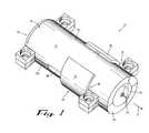
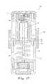
- FIG. 1is a perspective view of a lancing device according to a first example embodiment of the present invention.
- FIG. 2is a longitudinal cross-section view of the lancing device of FIG. 1 , with the lancet carrier in a retracted position for cocking the device.
- FIG. 3is a longitudinal cross-section view of the lancing device of FIG. 1 , in an armed state.
- FIG. 4is a longitudinal cross-section view of the lancing device of FIG. 1 , with the lancet in an extended position of the lancing stroke for puncturing the skin.
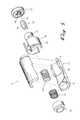
- FIG. 5is an exploded perspective view of a lancing device according to a second example embodiment of the present invention.
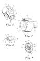
- FIG. 6is a front perspective view of a carrier of the lancing device of FIG. 5 .
- FIG. 7is a rear perspective view of a carrier of the lancing device of FIG. 5 .
- FIG. 8is a front perspective view of a lancet of the lancing device of FIG. 5 .
- FIG. 9is a rear perspective view of an endcap of the lancing device of FIG. 5 .
- FIG. 10is a longitudinal cross-section view of the lancing device of FIG. 5 , with the lancet and carrier in a rest position.
- FIG. 11is a longitudinal cross-section view of the lancing device of FIG. 5 , with the lancet and carrier in a retracted position.
- FIG. 12is a cross-section view of the lancing device taken at line G-G of FIG. 11 .
- FIG. 13is a cross-section detail view, Detail “H” of FIG. 12 , showing the cocking arm catch being retained in place.
- FIG. 14is a longitudinal cross-section view of the lancing device of FIG. 5 , with the lancet and carrier in an activated or firing position.
- FIG. 15is a cross-section view of the lancing device taken at line J-J of FIG. 14 .
- FIG. 16is a cross-section detail view, Detail “K” of FIG. 15 , showing the cocking arm catch being released for firing.
- FIG. 17is a longitudinal cross-section view of the lancing device of FIG. 5 , with the carrier in a stopped position.
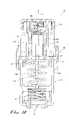
- FIG. 18is a longitudinal cross-section view of the lancing device of FIG. 5 , with the carrier stopped and the lancet continuing to the extended or puncturing position.
- FIG. 19is an exploded perspective view of the carrier (in cross section), lancet, and endcap of the lancing device of FIG. 5 .
- FIG. 20is a perspective view of the carrier (in cross section), lancet, and endcap of FIG. 19 , with the endcap in a safety position.
- FIG. 21is a perspective view of the carrier (in cross section), lancet, and endcap of FIG. 19 , with the endcap in a shallow puncturing depth position.
- FIG. 22is a perspective view of the carrier (in cross section), lancet, and endcap of FIG. 21 , with the lancet fired and in the puncturing position.
- FIG. 23is a perspective view of the carrier (in cross section), lancet, and endcap of FIG. 19 , with the endcap in a deep puncturing depth position.
- FIG. 24is a perspective view of the carrier (in cross section), lancet, and endcap of FIG. 23 , with the lancet fired and in the puncturing position.
- FIG. 25is a front view of the carrier and lancet of FIG. 19 .
- FIG. 26is a front view of an alternative lancet for use with the carrier and endcap of FIG. 19 .
- FIGS. 1-4show a lancing device 10 according to a first example embodiment of the invention.
- the device 10includes a housing 12 , preferably formed of two inter-engaging half-shells 12 a , 12 b .
- the housing 12has a proximal end 14 , a distal end 16 , and one or more sidewalls 18 .
- the housing 12is generally cylindrical and is formed of plastic and/or other substantially rigid material(s), as for example by injection molding. It will be understood that other housing configurations and materials may be suitably used.
- a penetrable foil covering or removable cap(unshown) preferably initially covers the opening at the proximal end 14 of the housing 12 to maintain sterility prior to use of the device 10 .
- a drive mechanismincludes a drive member such as a carrier 20 that is slidably mounted to the housing 12 .
- the carrier 20preferably includes a carriage 22 mounted within a channel 24 extending axially through the housing 12 , and one or more sleeves or wings 26 extending outwardly of the housing 12 and connected to the carriage by a strut 28 projecting through a slot 30 in the sidewall 18 of the housing.
- the carriage 22is preferably engaged within the channel 24 with a close sliding fit to minimize rocking and lateral motion, and to constrain the carriage to translation along an axial path parallel to direction arrow “a.”
- the struts 28preferably slide within the slot 30 with a close sliding fit, further defining the path of translation of the carrier 20 and preventing twisting of the carrier within the housing 12 .
- the sleeves or wings 26provide a gripping surface for the user to grasp to pull back the carrier 20 for cocking the lancing device.
- the wings 26may be provided by tabs, collars, finger rests, and other grasping members.
- the wings 26generally conform to the shape of the housing 12 and are in the form of sleeves that extend a majority of the way around the housing.
- a proximal hole or opening 32is formed in the proximal face of the carriage 22 of the carrier 20 for allowing passage of a lancet tip during lancing, as described below.
- a distal hole or opening 34is formed in the distal face of the carriage 22 of the carrier 20 for allowing passage through it of a cocking arm portion of the lancet sled, as described below.
- a stepped bore 36(including a track, channel, etc.) preferably extends axially through the carriage 22 of the carrier 20 , forming a distally-facing shoulder 38 .
- a lancet sled 40is slidably mounted within the bore 36 of the carriage 22 , and includes a lancet 42 having a sharp lancing tip 44 .
- the bore 36is preferably cylindrical, but it may have a square of other cross-sectional shape, if desired, and is axially longer than a body of the lancet 42 .
- the lancet 42may be integrally formed with the lancet sled 40 , for example, in a disposable lancing device embodiment. Or it may be a separate component secured to the sled, as by a friction fit within a receptacle of the sled as shown, for example, in a multi-use lancing device embodiment.
- the sled 40 and lancet 42preferably have a low mass relative to known lancet and drive mechanisms.
- a return spring 46is preferably engaged between a flange or projection 47 extending from the lancet sled, and the shoulder 38 of the carrier 20 .
- a cocking mechanismpreferably comprises at least one cocking arm 48 that extends distally from the lancet sled 40 and includes a catch such as a barb 50 for engaging an engagement surface such as a flange or shoulder 52 of the housing 12 to secure the sled and carrier arrangement in a cocked position, as shown in FIG. 2 .
- the cocking arm 48may extend from the carrier 20 , from the lancet 42 (e.g., in embodiments with the lancet and sled integrally formed as one piece), or from another component of the device 10 .
- the drive mechanismincludes a drive spring 54 that is preferably engaged between the carrier 20 and the housing 12 , for driving the lancet sled 40 and carrier 20 through a lancing stroke from the cocked position (see FIG. 2 ) to the extended position (see FIG. 4 ). It will be understood that other conventional cocking mechanisms may be suitably employed.
- a trigger mechanismincludes a trigger or release button 60 that is preferably mounted at the distal end 16 of the housing 12 .
- the release button 60includes a catch release member such as an inclined cam face 62 for engagement against a cooperating inclined face 63 or other catch release member of the cocking arm 48 .
- a spring 64is preferably provided to bias the release button 60 distally from the housing 12 .
- the inclined cam face 62engages the cooperating inclined face 63 to release the barb 50 from the shoulder 52 , thereby firing the device 10 and initiating a lancing operation. It will be understood that other conventional trigger mechanisms may be suitably employed.
- FIGS. 2-4depict a sequence of operation of the lancing device 10 and a first example method of lancing according to the present invention.
- the lancing device 10is preferably delivered to the user in an uncocked state, with the drive spring 54 substantially or partially relaxed.
- the usercocks the device 10 by gripping the housing 12 and the wings 26 , and pulling the wings (and thereby the carriage 22 and sled 40 ) distally relative to the housing, into the cocked position shown in FIG. 2 , with the drive spring 54 substantially fully compressed.
- the shoulder 38 of the carriage 22 and the flange 47 of the sled 40withdraws the sled distally along with the carrier during cocking.
- the sled 40When the lancing stroke begins, the sled 40 is retained in a retracted position, toward the distal end of the bore 36 in the carriage 22 .
- the sled 40is retracted in the back of the bore 36 as a result of the engagement of the barb 50 and the shoulder 52 holding the carrier back, combined with the forward bias of the drive spring 54 against the carrier 20 (see FIG. 3 ).
- the carrier 20After operating the trigger to fire the device 10 , the carrier 20 is released and now moves forward under the influence of the drive spring 54 , carrying the lancet sled 40 along with it.
- the carrier 20 and lancet sled 40move forward together until there is an impact with a carrier stop such as a proximal endwall 70 of the slot 30 of the housing 12 .
- the stoppingmay be caused by the carrier struts 28 impacting the housing slot proximal endwalls 70 , the carrier wings 126 impacting a protruding structure on the exterior of the housing 12 , or by other means. Inertia propels the lancet sled 40 forward after the carrier 20 stops, with the sled 40 and lancet 42 no longer being coupled to the carrier 20 or the spring 44 of the drive mechanism.
- the sled 40slides forward through the bore 36 to the extended position, shown in FIGS. 1 and 4 , wherein the sharp lancet tip 44 passes through the hole 32 and projects a distance beyond the proximal face of the housing 12 to puncture the subject's skin at the sampling site.
- the lancet sled 40is stopped in the extended position by a stop member such as an inside wall of the carriage, the housing, an endcap, or another structure.
- the lancet sled stop and the carrier stoppreferably are two separate structures, that is, they are not one and the same (even though they may both be defined by the endcap or the housing or another component of the lancing device).
- the low-mass sled 40 and lancet 42slide decoupled from the drive mechanism (i.e., they “float”) during that portion of the lancing stroke during which the skin is punctured, the subject senses less impact by the sharp lancet tip 44 against the skin than with known lancing devices. This significantly reduces the sensation of pain relative to that resulting from lancing with other devices.
- the return spring 46retracts the lancet sled 40 back through the bore 36 of the carriage 22 , withdrawing the sharp lancet tip 44 back into the housing 12 to prevent inadvertent needle sticks or bloodborne contamination.
- a penetration-depth adjustment mechanismis provided to allow adjustment of the depth of penetration of the lancet tip into the skin of the sampling site.
- the penetration-depth adjustment mechanismmay be provided by a rotatable endcap on the proximal end of the housing, with the endcap joined to the housing by a threaded connection permitting the endcap to be extended and retracted axially relative to the housing by twisting the endcap.
- the endcaphas one or more adjustably positionable internal stop members that limit the distance of travel of a lancet.
- FIGS. 5-24show a lancing device 110 according to a second example embodiment of the invention.
- the lancing device 110is similar to the lancing device 10 of the first example embodiment. Structural differences include the device 110 combining the carrier and sled into one component, and the addition of an innovative penetration depth adjustment mechanism, as described below.
- the lancing device 110includes a housing 112 , a drive mechanism, a lancet 142 , a cocking mechanism, a trigger mechanism, and an endcap 172 .
- the housing 112has a proximal end, a distal end, and one or more sidewalls.
- the endcap 172preferably includes an opening or passage through which a lancing tip extends for puncturing.
- the endcapis separate from and attached to the housing.
- the endcapmay be integrally formed with the housing into a single piece without depth adjustment capability, in which case the endcap is essentially an endwall of the housing.
- the term “endcap” as used hereinincludes any structure at the proximal end of the housing, whether separate from or integral to the housing.
- the drive mechanismincludes a lancet carrier 120 , shown with particularity in FIGS. 6 and 7 .
- the lancet carrier 120preferably includes a carriage 122 mounted within a chamber 124 extending axially through the housing 112 , and one or more sleeves or wings 126 extending outwardly of the housing and connected to the carriage by a strut 128 projecting through a slot 130 in the housing.
- the carriage 122translations along an axial path parallel to direction arrow “a.”
- a proximal hole or openingis formed at the proximal end of the carriage 122 of the carrier 120 for allowing passage of a lancet tip during lancing, as described below.
- a bore 136preferably extends axially through the carriage 122 of the carrier 120 .
- the bore 136is preferably cylindrical, but it may have a square of other cross-sectional shape, if desired.
- the drive mechanismfurther includes a drive spring 154 that is preferably engaged between the carrier 120 and the housing 112 , for driving the carrier and lancet 142 through a lancing stroke from the cocked position (see FIG. 14 ) to the extended position (see FIG. 19 ).
- the lancet 142is preferably slidably mounted within the bore 136 of the carriage 122 , and includes a lancet body 143 and a sharp lancing tip 144 .
- the bore 136is preferably cylindrical, but it may have a square of other cross-sectional shape, if desired, and is axially longer than the lancet body 143 .
- the carriage 122may be provided by a disc, piston, finger, or other drive member that pushes the lancet 142 , but that does not have a bore for receiving it, so that the lancet sliding floats relative to the carriage and in the chamber 124 .
- the lancet 42may be of a conventional type, or it may have special features for cooperating with the endcap to control the penetration depth, as described below.
- the lancet 142preferably has a low mass relative to known lancets.
- a return spring 146is preferably engaged between the lancet body 143 and the endcap 172 .
- the cocking mechanismpreferably comprises at least one cocking arm and engagement surface for securing the carrier in a cocked position.
- the cocking mechanismhas two cocking arms 148 that extend distally from the carrier 140 , each with a catch such as a barb 150 for engaging an engagement surface such as a flange or shoulder 152 of the housing 112 , as shown in FIG. 13 .
- the trigger mechanismpreferably comprises a trigger spring 164 and a release button 160 .
- the release button 160preferably includes a catch release member such as an inclined cam face 162 for engagement against a cooperating inclined face 163 or other catch release member of the cocking arm 148 , as shown in FIG. 16 .
- the carrier 120is included in other lancing devices in which the lancet fits snugly therein without slidably floating therein so that the lancet and carrier do not decouple during the lancing stroke.
- the carriage of the carrieracts as a conventional lancet holder.
- Such lancing devicesmay include the cocking and trigger mechanisms described herein or others. While these lancing devices do not produce the pain-reducing advantages associated with decoupling the lancet from the drive mechanism, they nevertheless provide improved guidance and control of the lancet, which tends to reduce lateral movement and rocking of the lancet and thereby reduce pain sensed during puncturing.
- FIGS. 10-18depict a sequence of operation of the lancing device 110 and a second example method of lancing according to the present invention.
- the lancing device 110is preferably delivered to the user in an uncocked, rest state, with the drive spring 54 substantially or partially relaxed.
- the usercocks the device 110 by gripping the housing 112 and the wings 126 , and pulling the wings (and thereby the carriage 122 and lancet 142 ) distally relative to the housing, into the cocked position shown in FIGS. 11-13 , with the drive spring 154 substantially fully compressed.
- the return spring 146withdraws the lancet 142 distally along with the carrier 120 during cocking. Engagement of the cocking arm catch barb 150 with the engagement shoulder 152 retains the carrier 120 in the cocked position after the wings 126 are released, as shown in FIG. 13 .
- the device 110is fired to complete the lancing operation by pressing the release button 160 , as shown in FIGS. 14-16 .
- the inclined face 162 of the release button 160contacts the cooperating inclined face 163 of the cocking arm 148 and disengages the catch barb 150 from the engagement shoulder 152 , as shown in FIG. 16 .
- the trigger mechanismUpon operating the trigger mechanism, the carrier 120 is released and the lancing stroke is initiated.
- the carrier 120is now propelled forward under the influence of the drive spring 154 , carrying the lancet 142 along with it.
- the carrier 120 and lancet 142move forward together until there is an impact with a carrier stop such as a proximal endwall 170 of the slot 130 in the housing 112 .
- a carrier stopsuch as a proximal endwall 170 of the slot 130 in the housing 112 .
- the stoppingmay be caused by the carrier struts 128 impacting the housing slot proximal endwalls 170 (as shown in FIG. 17 ), a proximal face of the carriage 122 impacting a distal face of the endcap 172 , or by other means.
- Inertiapropels the lancet 142 forward after the carrier 120 stops, with the lancet 142 no longer being coupled to the carrier 120 or the spring 144 of the drive mechanism.
- the lancet 142slides forward through the bore 136 of the carriage 122 to the extended position, shown in FIG. 18 , wherein the sharp lancet tip 144 passes through a hole or opening 132 in the endcap 172 and projects a distance beyond the endcap to puncture the subject's skin at the sampling site. Because the low-mass lancet 142 floats decoupled from the drive mechanism of the device 110 during that portion of the lancing stroke during which the skin is punctured, the subject senses less impact by the sharp lancet tip 144 against the skin than with known lancing devices. This significantly reduces the sensation of pain relative to that resulting from lancing with other devices.
- the return spring 146retracts the lancet 142 back through the bore 136 of the carriage 122 , withdrawing the sharp lancet tip 144 back into the housing 112 to prevent inadvertent needle sticks or bloodborne contamination.
- a penetration-depth adjustment mechanismmay be provided to allow adjustment of the depth of penetration of the lancet tip into the skin of the sampling site.
- the penetration-depth adjustment mechanismmay be provided by a uniquely configured carrier 120 , lancet 142 , and endcap 172 , as shown in FIGS. 6-9 and 19 - 25 .
- the carrier 120 and the lancet 142are keyed so that they fit together in a specific orientation.
- the lancet 142has at least one male key member and the carrier 120 has at least one female key member, or vice versa, that cooperate to properly orient the lancet.
- the lancet 142has at least one contact surface and the endcap 172 has a plurality of stop surfaces, or vice versa, for adjusting the puncturing depth of the lancet tip.
- the lancet body 143comprises four arms 174 in the shape of a “t” with two opposing ones of the arms having outer portions 174 a making them longer than the other two arms (see FIGS. 8 and 25 ).
- the two male key members and two contact surfacesare formed by the same structure, namely, the two outer portions 174 a of the arms 174 of the lancet body 143 .
- the two arm outer portions 174 aare received in two female key channels 176 in the carrier 120 to properly orient the lancet 142 (see FIGS. 6 , 18 , 19 , and 25 ).
- the two arm outer portions 174 aselectively engage two sets of three stop surfaces 178 a , 178 b , and 178 c (collectively, the “stop surfaces 178 ”) defined by protrusions 180 a , 180 b , and 180 c (collectively, the “protrusions 180 ”) extending distally from the endcap 172 (see FIGS. 9 , 18 and 19 ). It will be understood that another number of protrusions 180 and stop surfaces 178 may be provided, as may be desired for a given application.
- the protrusions 180are circumferentially arranged relative to the lancet 142 , so that the arms 174 without outer portions 174 a are circumscribed by the circumferential protrusions, but the outer portions interfere with the protrusions when they are in alignment (see FIG. 25 ).
- the endcap 172can be rotated so that one of the three protrusions 180 of each protrusion set aligns with and contacts the two outer portions 174 a to stop the lancet 142 , while the other two protrusions of each set are out of alignment with the outer portions and do not interfere with the lancet.
- the carriage 122has a flared proximal section 122 a with a flared bore 136 a that receives the two protrusions 180 that are not aligned with the outer portions 174 a of the longer arms 174 (see FIGS. 6 , 18 , and 25 ).
- the flared bore 136 ahas a larger diameter or other size-indicating dimension than the bore 136 .
- FIGS. 20-24show the use of the adjustment mechanism and a method of adjusting a lancing device for various penetration depth settings.
- the endcap 172is positioned with the first/longest protrusions 180 a aligned with the arm outer portions 174 a , so that if the lancing device is accidentally fired the lancing tip 144 will not extend beyond the endcap.
- the endcap 172has been rotated (in the direction of arrow “r”) to a shallow puncturing depth position with the second/intermediate length protrusions 180 b aligned with the arm outer portions 174 a .
- the lancet 142has been fired and is in the puncturing position, with the second/intermediate length protrusions 180 b contacting the arm outer portions 174 a to stop the lancet in the shallow puncturing depth position.
- the endcap 172has been rotated farther to a deep puncturing depth position with the third/shortest length protrusions 180 c aligned with the arm outer portions 174 a .
- the lancet 142has been fired and is in the puncturing position, with the third/shortest length protrusions 180 c contacting the arm outer portions 174 a to stop the lancet later, in the deep puncturing depth position.
- the adjustment mechanismcan be provided in alternative forms.
- the carrier 120 and the endcap 172are the same, but the lancet 242 has a body 243 that generally conforms to the shape of the bore 136 defined in the carriage 122 and that has outer portions 274 a extending therefrom (see FIG. 26 ).
- the endcap protrusions that are not aligned with the outer portionsare received in recesses in the lancet body to avoid movement-limiting interference with the lancet.
- the adjustment mechanismis included in lancing device with a lancet that is coupled to the drive mechanism so that it does not float separately therefrom, with the female key channels or other structures being defined in the housing or another component of the lancing device.
- the present inventionprovides advantages over other lancing devices.
- the present inventionincludes lancing devices in which the drive mechanism is decoupled from lancet so that, when the skin is pierced, the lancet floats free of the mass of the drive mechanism. Because of this decoupling and free-floating, there is less mass behind the lancet tip when impacting the skin, which reduces the pain felt by the user.
- the drive springis decoupled from the lancet when the skin is pierced, this prevents restrikes from spring-induced lancet oscillations.
- the lancethas a high velocity relative to previous lancing devices because of the reduced mass/energy ratio from decoupling the lancet from the drive mechanism.
Landscapes
- Health & Medical Sciences (AREA)
- Life Sciences & Earth Sciences (AREA)
- Heart & Thoracic Surgery (AREA)
- Medical Informatics (AREA)
- Biophysics (AREA)
- Pathology (AREA)
- Engineering & Computer Science (AREA)
- Biomedical Technology (AREA)
- Hematology (AREA)
- Physics & Mathematics (AREA)
- Molecular Biology (AREA)
- Surgery (AREA)
- Animal Behavior & Ethology (AREA)
- General Health & Medical Sciences (AREA)
- Public Health (AREA)
- Veterinary Medicine (AREA)
- Dermatology (AREA)
- Measurement Of The Respiration, Hearing Ability, Form, And Blood Characteristics Of Living Organisms (AREA)
Abstract
Description
Claims (4)
Priority Applications (1)
| Application Number | Priority Date | Filing Date | Title |
|---|---|---|---|
| US12/346,193US8142466B2 (en) | 2003-03-24 | 2008-12-30 | Lancing device with floating lancet |
Applications Claiming Priority (3)
| Application Number | Priority Date | Filing Date | Title |
|---|---|---|---|
| US45692703P | 2003-03-24 | 2003-03-24 | |
| US10/807,901US7494498B2 (en) | 2003-03-24 | 2004-03-24 | Lancing device with floating lancet |
| US12/346,193US8142466B2 (en) | 2003-03-24 | 2008-12-30 | Lancing device with floating lancet |
Related Parent Applications (1)
| Application Number | Title | Priority Date | Filing Date |
|---|---|---|---|
| US10/807,901ContinuationUS7494498B2 (en) | 2003-03-24 | 2004-03-24 | Lancing device with floating lancet |
Publications (2)
| Publication Number | Publication Date |
|---|---|
| US20090105741A1 US20090105741A1 (en) | 2009-04-23 |
| US8142466B2true US8142466B2 (en) | 2012-03-27 |
Family
ID=33519049
Family Applications (2)
| Application Number | Title | Priority Date | Filing Date |
|---|---|---|---|
| US10/807,901Active2026-02-25US7494498B2 (en) | 2003-03-24 | 2004-03-24 | Lancing device with floating lancet |
| US12/346,193Expired - LifetimeUS8142466B2 (en) | 2003-03-24 | 2008-12-30 | Lancing device with floating lancet |
Family Applications Before (1)
| Application Number | Title | Priority Date | Filing Date |
|---|---|---|---|
| US10/807,901Active2026-02-25US7494498B2 (en) | 2003-03-24 | 2004-03-24 | Lancing device with floating lancet |
Country Status (1)
| Country | Link |
|---|---|
| US (2) | US7494498B2 (en) |
Cited By (2)
| Publication number | Priority date | Publication date | Assignee | Title |
|---|---|---|---|---|
| US20110224712A1 (en)* | 2009-10-15 | 2011-09-15 | Roche Diagnostics Operations, Inc. | Lancing system for withdrawing a body fluid |
| US9844331B2 (en) | 2011-12-15 | 2017-12-19 | Facet Technologies, Llc | Latch mechanism for preventing lancet oscillation in a lancing device |
Families Citing this family (98)
| Publication number | Priority date | Publication date | Assignee | Title |
|---|---|---|---|---|
| US6036924A (en) | 1997-12-04 | 2000-03-14 | Hewlett-Packard Company | Cassette of lancet cartridges for sampling blood |
| US6391005B1 (en) | 1998-03-30 | 2002-05-21 | Agilent Technologies, Inc. | Apparatus and method for penetration with shaft having a sensor for sensing penetration depth |
| US7175641B1 (en) | 1998-06-11 | 2007-02-13 | Stat Medical Devices, Inc. | Lancet having adjustable penetration depth |
| US8641644B2 (en) | 2000-11-21 | 2014-02-04 | Sanofi-Aventis Deutschland Gmbh | Blood testing apparatus having a rotatable cartridge with multiple lancing elements and testing means |
| EP1395185B1 (en) | 2001-06-12 | 2010-10-27 | Pelikan Technologies Inc. | Electric lancet actuator |
| US9795747B2 (en) | 2010-06-02 | 2017-10-24 | Sanofi-Aventis Deutschland Gmbh | Methods and apparatus for lancet actuation |
| US7041068B2 (en) | 2001-06-12 | 2006-05-09 | Pelikan Technologies, Inc. | Sampling module device and method |
| US7344507B2 (en) | 2002-04-19 | 2008-03-18 | Pelikan Technologies, Inc. | Method and apparatus for lancet actuation |
| US8337419B2 (en) | 2002-04-19 | 2012-12-25 | Sanofi-Aventis Deutschland Gmbh | Tissue penetration device |
| US9226699B2 (en) | 2002-04-19 | 2016-01-05 | Sanofi-Aventis Deutschland Gmbh | Body fluid sampling module with a continuous compression tissue interface surface |
| JP4272051B2 (en) | 2001-06-12 | 2009-06-03 | ペリカン テクノロジーズ インコーポレイテッド | Blood sampling apparatus and method |
| JP4209767B2 (en) | 2001-06-12 | 2009-01-14 | ペリカン テクノロジーズ インコーポレイテッド | Self-optimized cutting instrument with adaptive means for temporary changes in skin properties |
| AU2002344825A1 (en) | 2001-06-12 | 2002-12-23 | Pelikan Technologies, Inc. | Method and apparatus for improving success rate of blood yield from a fingerstick |
| WO2002101359A2 (en) | 2001-06-12 | 2002-12-19 | Pelikan Technologies, Inc. | Integrated blood sampling analysis system with multi-use sampling module |
| US7749174B2 (en) | 2001-06-12 | 2010-07-06 | Pelikan Technologies, Inc. | Method and apparatus for lancet launching device intergrated onto a blood-sampling cartridge |
| US9427532B2 (en) | 2001-06-12 | 2016-08-30 | Sanofi-Aventis Deutschland Gmbh | Tissue penetration device |
| US7981056B2 (en) | 2002-04-19 | 2011-07-19 | Pelikan Technologies, Inc. | Methods and apparatus for lancet actuation |
| US7344894B2 (en) | 2001-10-16 | 2008-03-18 | Agilent Technologies, Inc. | Thermal regulation of fluidic samples within a diagnostic cartridge |
| US7232451B2 (en) | 2002-04-19 | 2007-06-19 | Pelikan Technologies, Inc. | Method and apparatus for penetrating tissue |
| US7374544B2 (en) | 2002-04-19 | 2008-05-20 | Pelikan Technologies, Inc. | Method and apparatus for penetrating tissue |
| US8372016B2 (en) | 2002-04-19 | 2013-02-12 | Sanofi-Aventis Deutschland Gmbh | Method and apparatus for body fluid sampling and analyte sensing |
| US8267870B2 (en) | 2002-04-19 | 2012-09-18 | Sanofi-Aventis Deutschland Gmbh | Method and apparatus for body fluid sampling with hybrid actuation |
| US7648468B2 (en) | 2002-04-19 | 2010-01-19 | Pelikon Technologies, Inc. | Method and apparatus for penetrating tissue |
| US7485128B2 (en) | 2002-04-19 | 2009-02-03 | Pelikan Technologies, Inc. | Method and apparatus for penetrating tissue |
| US9314194B2 (en) | 2002-04-19 | 2016-04-19 | Sanofi-Aventis Deutschland Gmbh | Tissue penetration device |
| US7708701B2 (en) | 2002-04-19 | 2010-05-04 | Pelikan Technologies, Inc. | Method and apparatus for a multi-use body fluid sampling device |
| US8221334B2 (en) | 2002-04-19 | 2012-07-17 | Sanofi-Aventis Deutschland Gmbh | Method and apparatus for penetrating tissue |
| US7717863B2 (en) | 2002-04-19 | 2010-05-18 | Pelikan Technologies, Inc. | Method and apparatus for penetrating tissue |
| US7547287B2 (en) | 2002-04-19 | 2009-06-16 | Pelikan Technologies, Inc. | Method and apparatus for penetrating tissue |
| US7524293B2 (en) | 2002-04-19 | 2009-04-28 | Pelikan Technologies, Inc. | Method and apparatus for penetrating tissue |
| US8579831B2 (en) | 2002-04-19 | 2013-11-12 | Sanofi-Aventis Deutschland Gmbh | Method and apparatus for penetrating tissue |
| US8784335B2 (en) | 2002-04-19 | 2014-07-22 | Sanofi-Aventis Deutschland Gmbh | Body fluid sampling device with a capacitive sensor |
| US7563232B2 (en) | 2002-04-19 | 2009-07-21 | Pelikan Technologies, Inc. | Method and apparatus for penetrating tissue |
| US7141058B2 (en) | 2002-04-19 | 2006-11-28 | Pelikan Technologies, Inc. | Method and apparatus for a body fluid sampling device using illumination |
| US7976476B2 (en) | 2002-04-19 | 2011-07-12 | Pelikan Technologies, Inc. | Device and method for variable speed lancet |
| US7331931B2 (en) | 2002-04-19 | 2008-02-19 | Pelikan Technologies, Inc. | Method and apparatus for penetrating tissue |
| US7244265B2 (en) | 2002-04-19 | 2007-07-17 | Pelikan Technologies, Inc. | Method and apparatus for penetrating tissue |
| US7892183B2 (en) | 2002-04-19 | 2011-02-22 | Pelikan Technologies, Inc. | Method and apparatus for body fluid sampling and analyte sensing |
| US9248267B2 (en) | 2002-04-19 | 2016-02-02 | Sanofi-Aventis Deustchland Gmbh | Tissue penetration device |
| US7491178B2 (en) | 2002-04-19 | 2009-02-17 | Pelikan Technologies, Inc. | Method and apparatus for penetrating tissue |
| US7297122B2 (en) | 2002-04-19 | 2007-11-20 | Pelikan Technologies, Inc. | Method and apparatus for penetrating tissue |
| US7229458B2 (en) | 2002-04-19 | 2007-06-12 | Pelikan Technologies, Inc. | Method and apparatus for penetrating tissue |
| US9795334B2 (en) | 2002-04-19 | 2017-10-24 | Sanofi-Aventis Deutschland Gmbh | Method and apparatus for penetrating tissue |
| US7410468B2 (en) | 2002-04-19 | 2008-08-12 | Pelikan Technologies, Inc. | Method and apparatus for penetrating tissue |
| WO2003088824A2 (en) | 2002-04-19 | 2003-10-30 | Pelikan Technologies, Inc. | Device and method for variable speed lancet |
| US7901362B2 (en) | 2002-04-19 | 2011-03-08 | Pelikan Technologies, Inc. | Method and apparatus for penetrating tissue |
| US8360992B2 (en) | 2002-04-19 | 2013-01-29 | Sanofi-Aventis Deutschland Gmbh | Method and apparatus for penetrating tissue |
| US7909778B2 (en) | 2002-04-19 | 2011-03-22 | Pelikan Technologies, Inc. | Method and apparatus for penetrating tissue |
| US8702624B2 (en) | 2006-09-29 | 2014-04-22 | Sanofi-Aventis Deutschland Gmbh | Analyte measurement device with a single shot actuator |
| US7291117B2 (en) | 2002-04-19 | 2007-11-06 | Pelikan Technologies, Inc. | Method and apparatus for penetrating tissue |
| US7371247B2 (en) | 2002-04-19 | 2008-05-13 | Pelikan Technologies, Inc | Method and apparatus for penetrating tissue |
| US7674232B2 (en) | 2002-04-19 | 2010-03-09 | Pelikan Technologies, Inc. | Method and apparatus for penetrating tissue |
| US8574895B2 (en) | 2002-12-30 | 2013-11-05 | Sanofi-Aventis Deutschland Gmbh | Method and apparatus using optical techniques to measure analyte levels |
| US7494498B2 (en) | 2003-03-24 | 2009-02-24 | Facet Technologies, Llc | Lancing device with floating lancet |
| US20040254599A1 (en)* | 2003-03-25 | 2004-12-16 | Lipoma Michael V. | Method and apparatus for pre-lancing stimulation of puncture site |
| DE602004028463D1 (en) | 2003-05-30 | 2010-09-16 | Pelikan Technologies Inc | METHOD AND DEVICE FOR INJECTING LIQUID |
| US7850621B2 (en) | 2003-06-06 | 2010-12-14 | Pelikan Technologies, Inc. | Method and apparatus for body fluid sampling and analyte sensing |
| WO2006001797A1 (en) | 2004-06-14 | 2006-01-05 | Pelikan Technologies, Inc. | Low pain penetrating |
| EP1635700B1 (en) | 2003-06-13 | 2016-03-09 | Sanofi-Aventis Deutschland GmbH | Apparatus for a point of care device |
| US7905898B2 (en) | 2003-08-15 | 2011-03-15 | Stat Medical Devices, Inc. | Adjustable lancet device and method |
| US8282576B2 (en) | 2003-09-29 | 2012-10-09 | Sanofi-Aventis Deutschland Gmbh | Method and apparatus for an improved sample capture device |
| EP1680014A4 (en) | 2003-10-14 | 2009-01-21 | Pelikan Technologies Inc | METHOD AND DEVICE FOR A VARIABLE USER INTERFACE |
| EP1684634A2 (en)* | 2003-11-12 | 2006-08-02 | Facet Technologies, LLC | Lancing device and multi-lancet cartridge |
| US8668656B2 (en) | 2003-12-31 | 2014-03-11 | Sanofi-Aventis Deutschland Gmbh | Method and apparatus for improving fluidic flow and sample capture |
| US7822454B1 (en) | 2005-01-03 | 2010-10-26 | Pelikan Technologies, Inc. | Fluid sampling device with improved analyte detecting member configuration |
| WO2006011062A2 (en) | 2004-05-20 | 2006-02-02 | Albatros Technologies Gmbh & Co. Kg | Printable hydrogel for biosensors |
| US9775553B2 (en) | 2004-06-03 | 2017-10-03 | Sanofi-Aventis Deutschland Gmbh | Method and apparatus for a fluid sampling device |
| WO2005120365A1 (en) | 2004-06-03 | 2005-12-22 | Pelikan Technologies, Inc. | Method and apparatus for a fluid sampling device |
| US8652831B2 (en) | 2004-12-30 | 2014-02-18 | Sanofi-Aventis Deutschland Gmbh | Method and apparatus for analyte measurement test time |
| US7775991B2 (en)* | 2005-08-31 | 2010-08-17 | Kimberly-Clark Worldwide, Inc. | Device for sampling blood |
| EP1772099B8 (en)* | 2005-10-08 | 2011-10-05 | Roche Diagnostics GmbH | Piercing system |
| US7704265B2 (en) | 2005-11-03 | 2010-04-27 | Stat Medical Devices, Inc. | Disposable/single-use blade lancet device and method |
| EP1852069B1 (en)* | 2006-05-04 | 2015-06-17 | Roche Diagnostics GmbH | System for sampling blood from a body part |
| US7909842B2 (en)* | 2006-06-15 | 2011-03-22 | Abbott Diabetes Care Inc. | Lancing devices having depth adjustment assembly |
| US8469986B2 (en) | 2007-03-30 | 2013-06-25 | Stat Medical Devices, Inc. | Lancet device with combined trigger and cocking mechanism and method |
| PL213006B1 (en)* | 2007-04-19 | 2012-12-31 | Htl Strefa Spolka Akcyjna | Device for needling of patient's skin |
| EP2265324B1 (en) | 2008-04-11 | 2015-01-28 | Sanofi-Aventis Deutschland GmbH | Integrated analyte measurement system |
| EP2346418A1 (en)* | 2008-10-14 | 2011-07-27 | Gérard Scortecci | Surgical device for tissue perforation |
| US9375169B2 (en) | 2009-01-30 | 2016-06-28 | Sanofi-Aventis Deutschland Gmbh | Cam drive for managing disposable penetrating member actions with a single motor and motor and control system |
| JP2010233803A (en)* | 2009-03-31 | 2010-10-21 | Sysmex Corp | Puncture instrument for forming micropore |
| US20100274858A1 (en)* | 2009-04-27 | 2010-10-28 | Nokia Corporation | Mid-service sharing |
| US9055899B2 (en)* | 2009-10-22 | 2015-06-16 | Facet Technologies, Llc | Lancing device with improved guidance assembly |
| CA2786538A1 (en)* | 2010-01-13 | 2011-07-21 | Facet Technologies, Llc | Lancing device with improved guidance mechanism |
| US8657763B2 (en) | 2010-01-19 | 2014-02-25 | Christopher A. Jacobs | Vacuum assisted lancing system with elective vacuum release and method for blood extraction with minimal pain |
| US8460211B2 (en)* | 2010-01-19 | 2013-06-11 | Christopher A. Jacobs | Vacuum assisted lancing system with bidirectional mechanism and method for blood extraction with minimal pain |
| JP4585041B2 (en)* | 2010-03-15 | 2010-11-24 | パナソニック株式会社 | Puncture needle cartridge |
| JP4585040B2 (en)* | 2010-03-15 | 2010-11-24 | パナソニック株式会社 | Puncture needle cartridge |
| US8965476B2 (en) | 2010-04-16 | 2015-02-24 | Sanofi-Aventis Deutschland Gmbh | Tissue penetration device |
| US9999384B2 (en) | 2011-03-09 | 2018-06-19 | Becton, Dickinson And Company | Sleeve for removable lancet of lancing device |
| KR101361112B1 (en) | 2011-07-26 | 2014-02-13 | 주식회사 지엠엠씨 | A safty lancet for anti reuse |
| JP5930688B2 (en) | 2011-12-09 | 2016-06-08 | アークレイ株式会社 | Lancet cartridge |
| US20140052023A1 (en)* | 2012-08-15 | 2014-02-20 | Charles D. Starnes | Single Use Lancet Assembly |
| EP3868304A1 (en)* | 2013-01-18 | 2021-08-25 | Merit Medical Systems, Inc. | Biopsy device with transfer of kinetic energy to the needle assembly |
| JP6014518B2 (en)* | 2013-03-01 | 2016-10-25 | シスメックス株式会社 | Puncture device |
| EP2823762B1 (en) | 2013-07-08 | 2015-08-19 | Roche Diagniostics GmbH | Lancing actuator |
| ES2760649T3 (en)* | 2015-02-24 | 2020-05-14 | Facet Tech Llc | Single-use compression lancing device |
| CN110856664B (en)* | 2018-08-23 | 2022-03-25 | 武汉联影智融医疗科技有限公司 | Surgical robot and puncture mechanism thereof |
| CN111685842B (en)* | 2020-07-23 | 2023-12-29 | 内蒙古善水医院有限公司 | Release that eases based on patient's position of inserting needle for blood purification |
Citations (56)
| Publication number | Priority date | Publication date | Assignee | Title |
|---|---|---|---|---|
| US4449529A (en) | 1981-11-18 | 1984-05-22 | Becton Dickinson And Company | Automatic retractable lancet assembly |
| US4503856A (en) | 1981-06-29 | 1985-03-12 | Sherwood Medical Company | Lancet injector |
| US4527561A (en) | 1981-03-23 | 1985-07-09 | Becton, Dickinson And Company | Automatic retractable lancet assembly |
| US4616649A (en) | 1984-09-20 | 1986-10-14 | Becton, Dickinson And Company | Lancet |
| US4817603A (en) | 1986-07-30 | 1989-04-04 | Glyme Valley Technology Limited | Lancet device |
| USRE32922E (en) | 1983-01-13 | 1989-05-16 | Paul D. Levin | Blood sampling instrument |
| US4895147A (en) | 1988-10-28 | 1990-01-23 | Sherwood Medical Company | Lancet injector |
| US4924879A (en) | 1988-10-07 | 1990-05-15 | Brien Walter J O | Blood lancet device |
| US4990154A (en) | 1989-06-19 | 1991-02-05 | Miles Inc. | Lancet assembly |
| US5282822A (en) | 1993-01-19 | 1994-02-01 | Sherwood Medical Company | Lancet ejector for lancet injector |
| US5318584A (en) | 1992-04-13 | 1994-06-07 | Boehringer Mannheim Gmbh | Blood lancet device for withdrawing blood for diagnostic purposes |
| US5356420A (en) | 1992-08-03 | 1994-10-18 | Przedsiebiorstwo Zagraniczne Htl | Device for puncturing |
| US5368047A (en) | 1993-04-28 | 1994-11-29 | Nissho Corporation | Suction-type blood sampler |
| US5569287A (en) | 1993-12-09 | 1996-10-29 | Fuji Photo Film Co., Ltd. | Means for collecting and spotting small amount of blood |
| US5611809A (en) | 1994-11-04 | 1997-03-18 | Owen Mumford Limited | Needle devices for medical use |
| US5613978A (en) | 1996-06-04 | 1997-03-25 | Palco Laboratories | Adjustable tip for lancet device |
| US5628764A (en) | 1995-03-21 | 1997-05-13 | Schraga; Steven | Collar lancet device |
| USD379516S (en) | 1996-03-04 | 1997-05-27 | Bayer Corporation | Lancet |
| US5730753A (en) | 1995-07-28 | 1998-03-24 | Apls Co., Ltd. | Assembly for adjusting pricking depth of lancet |
| US5741288A (en) | 1996-06-27 | 1998-04-21 | Chemtrak, Inc. | Re-armable single-user safety finger stick device having reset for multiple use by a single patient |
| US5879311A (en) | 1996-05-17 | 1999-03-09 | Mercury Diagnostics, Inc. | Body fluid sampling device and methods of use |
| US5885211A (en) | 1993-11-15 | 1999-03-23 | Spectrix, Inc. | Microporation of human skin for monitoring the concentration of an analyte |
| US5908434A (en) | 1998-02-13 | 1999-06-01 | Schraga; Steven | Lancet device |
| US5916230A (en) | 1997-06-16 | 1999-06-29 | Bayer Corporation | Blood sampling device with adjustable end cap |
| US5938679A (en) | 1997-10-14 | 1999-08-17 | Hewlett-Packard Company | Apparatus and method for minimally invasive blood sampling |
| US5964718A (en) | 1997-11-21 | 1999-10-12 | Mercury Diagnostics, Inc. | Body fluid sampling device |
| US5984940A (en) | 1997-05-29 | 1999-11-16 | Atrion Medical Products, Inc. | Lancet device |
| US6022366A (en) | 1998-06-11 | 2000-02-08 | Stat Medical Devices Inc. | Lancet having adjustable penetration depth |
| US6045567A (en) | 1999-02-23 | 2000-04-04 | Lifescan Inc. | Lancing device causing reduced pain |
| US6086545A (en) | 1998-04-28 | 2000-07-11 | Amira Medical | Methods and apparatus for suctioning and pumping body fluid from an incision |
| US6139562A (en) | 1998-03-30 | 2000-10-31 | Agilent Technologies, Inc. | Apparatus and method for incising |
| US6197040B1 (en) | 1999-02-23 | 2001-03-06 | Lifescan, Inc. | Lancing device having a releasable connector |
| US6231531B1 (en) | 1999-04-09 | 2001-05-15 | Agilent Technologies, Inc. | Apparatus and method for minimizing pain perception |
| US6248120B1 (en) | 2000-01-10 | 2001-06-19 | P. Z. “HTL” Spolka Akcyjna | Puncturing device |
| US6283982B1 (en) | 1999-10-19 | 2001-09-04 | Facet Technologies, Inc. | Lancing device and method of sample collection |
| US20010027327A1 (en) | 1998-06-11 | 2001-10-04 | Stat Medical Devices Inc. | Adjustable length member such as a cap of a lancet device for adjusting penetration depth |
| US6306152B1 (en) | 1999-03-08 | 2001-10-23 | Agilent Technologies, Inc. | Lancet device with skin movement control and ballistic preload |
| US6322575B1 (en) | 2000-01-05 | 2001-11-27 | Steven Schraga | Lancet depth adjustment assembly |
| US20020029059A1 (en) | 2000-09-01 | 2002-03-07 | Purcell D. Glenn | Adjustable endcap for lancing device |
| US20030018282A1 (en) | 2001-07-20 | 2003-01-23 | Carlo Effenhauser | System for withdrawing small amounts of body fluid |
| US6514270B1 (en) | 2000-11-10 | 2003-02-04 | Steven Schraga | Single use lancet device |
| US6530937B1 (en) | 2000-01-28 | 2003-03-11 | Stat Medical Devices, Inc. | Adjustable tip for a lancet device and method |
| US6558402B1 (en) | 1999-08-03 | 2003-05-06 | Becton, Dickinson And Company | Lancer |
| US6613064B2 (en) | 2000-04-04 | 2003-09-02 | P.Z. “Htl” S.A. | Arrangement regulating depth of the puncture, used in the device for puncturing |
| US6645219B2 (en) | 2001-09-07 | 2003-11-11 | Amira Medical | Rotatable penetration depth adjusting arrangement |
| US20030225430A1 (en) | 1998-06-11 | 2003-12-04 | Stat Medical Devices Inc. | Lancet having adjustable penetration depth |
| US6660018B2 (en) | 1999-03-08 | 2003-12-09 | Agilent Technologies, Inc. | Multiple lancet device |
| US20040059366A1 (en) | 2001-01-12 | 2004-03-25 | Yoshiharu Sato | Punctur device, its manufacture method, pump mechanism and suction device |
| US6730046B1 (en) | 1999-09-29 | 2004-05-04 | Arkray, Inc. | Body fluid sampling apparatus |
| US20040098010A1 (en) | 2001-10-22 | 2004-05-20 | Glenn Davison | Confuser crown skin pricker |
| US20040254599A1 (en) | 2003-03-25 | 2004-12-16 | Lipoma Michael V. | Method and apparatus for pre-lancing stimulation of puncture site |
| US20040260326A1 (en) | 2003-03-24 | 2004-12-23 | Lipoma Michael V. | Lancing device with floating lancet |
| US20050038464A1 (en) | 2003-08-15 | 2005-02-17 | Stat Medical Devices, Inc. | Adjustable lancet device and method |
| US6929650B2 (en) | 2001-01-12 | 2005-08-16 | Arkray, Inc. | Lancing device |
| US6949111B2 (en) | 1998-02-13 | 2005-09-27 | Steven Schraga | Lancet device |
| US7288102B2 (en) | 2003-03-20 | 2007-10-30 | Facet Technologies, Llc | Lancing device with decoupled lancet |
Family Cites Families (3)
| Publication number | Priority date | Publication date | Assignee | Title |
|---|---|---|---|---|
| US5318854A (en)* | 1986-08-26 | 1994-06-07 | General Electric Co. | Polymer mixture based on a polybutylene terephthalate ester and a S-MA copolymer and films made thereof |
| US6158050A (en)* | 1997-12-16 | 2000-12-12 | Air-Lock, Incorporated | Spacesuit sizing and tension relief bearing |
| DE10057328B4 (en)* | 2000-11-17 | 2005-12-29 | Robert Schröder GmbH & Co. KG | Handle of a screwing tool |
- 2004
- 2004-03-24USUS10/807,901patent/US7494498B2/enactiveActive
- 2008
- 2008-12-30USUS12/346,193patent/US8142466B2/ennot_activeExpired - Lifetime
Patent Citations (69)
| Publication number | Priority date | Publication date | Assignee | Title |
|---|---|---|---|---|
| US4527561A (en) | 1981-03-23 | 1985-07-09 | Becton, Dickinson And Company | Automatic retractable lancet assembly |
| US4535769A (en) | 1981-03-23 | 1985-08-20 | Becton, Dickinson And Company | Automatic retractable lancet assembly |
| US4553541A (en) | 1981-03-23 | 1985-11-19 | Becton, Dickinson And Co. | Automatic retractable lancet assembly |
| US4503856A (en) | 1981-06-29 | 1985-03-12 | Sherwood Medical Company | Lancet injector |
| US4449529A (en) | 1981-11-18 | 1984-05-22 | Becton Dickinson And Company | Automatic retractable lancet assembly |
| USRE32922E (en) | 1983-01-13 | 1989-05-16 | Paul D. Levin | Blood sampling instrument |
| US4616649A (en) | 1984-09-20 | 1986-10-14 | Becton, Dickinson And Company | Lancet |
| US4817603A (en) | 1986-07-30 | 1989-04-04 | Glyme Valley Technology Limited | Lancet device |
| US4924879A (en) | 1988-10-07 | 1990-05-15 | Brien Walter J O | Blood lancet device |
| US4895147A (en) | 1988-10-28 | 1990-01-23 | Sherwood Medical Company | Lancet injector |
| US4990154A (en) | 1989-06-19 | 1991-02-05 | Miles Inc. | Lancet assembly |
| US5074872A (en) | 1989-06-19 | 1991-12-24 | Miles Inc. | Lancet assembly |
| US5318584A (en) | 1992-04-13 | 1994-06-07 | Boehringer Mannheim Gmbh | Blood lancet device for withdrawing blood for diagnostic purposes |
| US5356420A (en) | 1992-08-03 | 1994-10-18 | Przedsiebiorstwo Zagraniczne Htl | Device for puncturing |
| US5282822A (en) | 1993-01-19 | 1994-02-01 | Sherwood Medical Company | Lancet ejector for lancet injector |
| US5368047A (en) | 1993-04-28 | 1994-11-29 | Nissho Corporation | Suction-type blood sampler |
| US5885211A (en) | 1993-11-15 | 1999-03-23 | Spectrix, Inc. | Microporation of human skin for monitoring the concentration of an analyte |
| US5569287A (en) | 1993-12-09 | 1996-10-29 | Fuji Photo Film Co., Ltd. | Means for collecting and spotting small amount of blood |
| US5611809A (en) | 1994-11-04 | 1997-03-18 | Owen Mumford Limited | Needle devices for medical use |
| US5628764A (en) | 1995-03-21 | 1997-05-13 | Schraga; Steven | Collar lancet device |
| US5730753A (en) | 1995-07-28 | 1998-03-24 | Apls Co., Ltd. | Assembly for adjusting pricking depth of lancet |
| USD379516S (en) | 1996-03-04 | 1997-05-27 | Bayer Corporation | Lancet |
| US6056701A (en) | 1996-05-17 | 2000-05-02 | Amira Medical | Body fluid sampling device and methods of use |
| US5879311A (en) | 1996-05-17 | 1999-03-09 | Mercury Diagnostics, Inc. | Body fluid sampling device and methods of use |
| US5613978A (en) | 1996-06-04 | 1997-03-25 | Palco Laboratories | Adjustable tip for lancet device |
| US5741288A (en) | 1996-06-27 | 1998-04-21 | Chemtrak, Inc. | Re-armable single-user safety finger stick device having reset for multiple use by a single patient |
| US5984940A (en) | 1997-05-29 | 1999-11-16 | Atrion Medical Products, Inc. | Lancet device |
| US6156050A (en) | 1997-05-29 | 2000-12-05 | Atrion Medical Products, Inc. | Lancet device |
| US5916230A (en) | 1997-06-16 | 1999-06-29 | Bayer Corporation | Blood sampling device with adjustable end cap |
| US5938679A (en) | 1997-10-14 | 1999-08-17 | Hewlett-Packard Company | Apparatus and method for minimally invasive blood sampling |
| US5964718A (en) | 1997-11-21 | 1999-10-12 | Mercury Diagnostics, Inc. | Body fluid sampling device |
| US6969359B2 (en) | 1997-11-21 | 2005-11-29 | Roche Diagnostics Operations, Inc. | Body fluid sampling device |
| US6066103A (en) | 1997-11-21 | 2000-05-23 | Amira Medical | Body fluid sampling device |
| US6464649B1 (en) | 1997-11-21 | 2002-10-15 | Amira Medical | Body fluid sampling device |
| US5908434A (en) | 1998-02-13 | 1999-06-01 | Schraga; Steven | Lancet device |
| US6949111B2 (en) | 1998-02-13 | 2005-09-27 | Steven Schraga | Lancet device |
| US6139562A (en) | 1998-03-30 | 2000-10-31 | Agilent Technologies, Inc. | Apparatus and method for incising |
| US6171325B1 (en) | 1998-03-30 | 2001-01-09 | Ganapati R. Mauze | Apparatus and method for incising |
| US6176865B1 (en) | 1998-03-30 | 2001-01-23 | Agilent Technologies, Inc. | Apparatus and method for incising |
| US6086545A (en) | 1998-04-28 | 2000-07-11 | Amira Medical | Methods and apparatus for suctioning and pumping body fluid from an incision |
| US6022366A (en) | 1998-06-11 | 2000-02-08 | Stat Medical Devices Inc. | Lancet having adjustable penetration depth |
| US20010027327A1 (en) | 1998-06-11 | 2001-10-04 | Stat Medical Devices Inc. | Adjustable length member such as a cap of a lancet device for adjusting penetration depth |
| US20030225430A1 (en) | 1998-06-11 | 2003-12-04 | Stat Medical Devices Inc. | Lancet having adjustable penetration depth |
| US6156051A (en) | 1998-06-11 | 2000-12-05 | Stat Medical Devices Inc. | Lancet having adjustable penetration depth |
| US6197040B1 (en) | 1999-02-23 | 2001-03-06 | Lifescan, Inc. | Lancing device having a releasable connector |
| US6045567A (en) | 1999-02-23 | 2000-04-04 | Lifescan Inc. | Lancing device causing reduced pain |
| US6306152B1 (en) | 1999-03-08 | 2001-10-23 | Agilent Technologies, Inc. | Lancet device with skin movement control and ballistic preload |
| US6660018B2 (en) | 1999-03-08 | 2003-12-09 | Agilent Technologies, Inc. | Multiple lancet device |
| US6231531B1 (en) | 1999-04-09 | 2001-05-15 | Agilent Technologies, Inc. | Apparatus and method for minimizing pain perception |
| US6558402B1 (en) | 1999-08-03 | 2003-05-06 | Becton, Dickinson And Company | Lancer |
| US6730046B1 (en) | 1999-09-29 | 2004-05-04 | Arkray, Inc. | Body fluid sampling apparatus |
| US6283982B1 (en) | 1999-10-19 | 2001-09-04 | Facet Technologies, Inc. | Lancing device and method of sample collection |
| US6322575B1 (en) | 2000-01-05 | 2001-11-27 | Steven Schraga | Lancet depth adjustment assembly |
| US6248120B1 (en) | 2000-01-10 | 2001-06-19 | P. Z. “HTL” Spolka Akcyjna | Puncturing device |
| US20030088261A1 (en) | 2000-01-28 | 2003-05-08 | Stat Medical Device Inc. | Adjustable tip for a lancet device and method |
| US6530937B1 (en) | 2000-01-28 | 2003-03-11 | Stat Medical Devices, Inc. | Adjustable tip for a lancet device and method |
| US6613064B2 (en) | 2000-04-04 | 2003-09-02 | P.Z. “Htl” S.A. | Arrangement regulating depth of the puncture, used in the device for puncturing |
| US20020029059A1 (en) | 2000-09-01 | 2002-03-07 | Purcell D. Glenn | Adjustable endcap for lancing device |
| US6451040B1 (en) | 2000-09-01 | 2002-09-17 | Bayer Corporation | Adjustable endcap for lancing device |
| US6514270B1 (en) | 2000-11-10 | 2003-02-04 | Steven Schraga | Single use lancet device |
| US6929650B2 (en) | 2001-01-12 | 2005-08-16 | Arkray, Inc. | Lancing device |
| US20040059366A1 (en) | 2001-01-12 | 2004-03-25 | Yoshiharu Sato | Punctur device, its manufacture method, pump mechanism and suction device |
| US20030018282A1 (en) | 2001-07-20 | 2003-01-23 | Carlo Effenhauser | System for withdrawing small amounts of body fluid |
| US6645219B2 (en) | 2001-09-07 | 2003-11-11 | Amira Medical | Rotatable penetration depth adjusting arrangement |
| US20040098010A1 (en) | 2001-10-22 | 2004-05-20 | Glenn Davison | Confuser crown skin pricker |
| US7288102B2 (en) | 2003-03-20 | 2007-10-30 | Facet Technologies, Llc | Lancing device with decoupled lancet |
| US20040260326A1 (en) | 2003-03-24 | 2004-12-23 | Lipoma Michael V. | Lancing device with floating lancet |
| US20040254599A1 (en) | 2003-03-25 | 2004-12-16 | Lipoma Michael V. | Method and apparatus for pre-lancing stimulation of puncture site |
| US20050038464A1 (en) | 2003-08-15 | 2005-02-17 | Stat Medical Devices, Inc. | Adjustable lancet device and method |
Non-Patent Citations (10)
| Title |
|---|
| Bayer, "Ames Glucolet" lancing device; 2 pgs. |
| Bayer, "Microlet" lancing device; 2 pgs. |
| Bayer, "Vaculance" lancing device; 1 pg. |
| Bechton-Dickinson, "Autolance" lancing device; 2 pgs. |
| Lifescan, "Penlet II" lancing device; 2 pgs. |
| Lifescan/Johnson & Johnson, "Penlet Plus" lancing device; 2 pgs. |
| Palco, "Auto-Lancet" lancing device; 2 pgs. |
| Roche, "Autoclix" lancing device; 2 pgs. |
| Roche, "Soft Touch II" lancing device; 1 pg. |
| Sutor et al., "Bleeding from Standardized Skin Punctures: Automated Technic for Recording Time, Intensity, and Pattern of Bleeding", Jou.C.P., vol. 55, May 1971, pp. 541-549. |
Cited By (7)
| Publication number | Priority date | Publication date | Assignee | Title |
|---|---|---|---|---|
| US20110224712A1 (en)* | 2009-10-15 | 2011-09-15 | Roche Diagnostics Operations, Inc. | Lancing system for withdrawing a body fluid |
| US8398665B2 (en)* | 2009-10-15 | 2013-03-19 | Roche Diagnostics Operations, Inc. | Lancing system for withdrawing a body fluid |
| US9844331B2 (en) | 2011-12-15 | 2017-12-19 | Facet Technologies, Llc | Latch mechanism for preventing lancet oscillation in a lancing device |
| US10820849B2 (en) | 2011-12-15 | 2020-11-03 | Facet Technologies, Llc | Latch mechanism for preventing lancet oscillation in a lancing device |
| US11564603B2 (en) | 2011-12-15 | 2023-01-31 | Facet Technologies, Llc | Latch mechanism for preventing lancet oscillation in a lancing device |
| US11883171B2 (en) | 2011-12-15 | 2024-01-30 | Facet Technologies, Llc | Latch mechanism for preventing lancet oscillation in a lancing device |
| US12329524B2 (en) | 2011-12-15 | 2025-06-17 | Facet Technologies, Llc | Latch mechanism for preventing lancet oscillation in a lancing device |
Also Published As
| Publication number | Publication date |
|---|---|
| US20090105741A1 (en) | 2009-04-23 |
| US7494498B2 (en) | 2009-02-24 |
| US20040260326A1 (en) | 2004-12-23 |
Similar Documents
| Publication | Publication Date | Title |
|---|---|---|
| US8142466B2 (en) | Lancing device with floating lancet | |
| US7288102B2 (en) | Lancing device with decoupled lancet | |
| US20040254599A1 (en) | Method and apparatus for pre-lancing stimulation of puncture site | |
| US8034068B2 (en) | Compact multi-use lancing device | |
| US9095293B2 (en) | Lancing device and lancet | |
| CN100430028C (en) | Adjustable lancet device | |
| US7914547B2 (en) | Adjustable lancing devices and methods | |
| US20130267978A1 (en) | Push-to-charge lancing device | |
| EP2861143B1 (en) | Uni-directional drive mechanism for lancing device | |
| US20100145377A1 (en) | Lancing Device For Minimizing Pain | |
| US9386945B2 (en) | Blood lancing device | |
| JP2006136716A (en) | Integrated apparatus with combination of cutting part and auxiliary part | |
| JP2001523508A (en) | Body fluid sampling device | |
| US8512366B2 (en) | Lancing device with tethered depth-control mechanism | |
| KR20170120690A (en) | Attenuation type biopsy device and method of use | |
| KR101170757B1 (en) | Cam-actuated medical puncturing device and method | |
| KR100932946B1 (en) | Blood collector | |
| US10292634B2 (en) | Depth-adjust mechanism for lancing device | |
| KR20230076130A (en) | Lancing device and how to use it | |
| CN117442248A (en) | Gun-retreating type biopsy ablation gun and biopsy ablation method | |
| MXPA98004004A (en) | Device for taking fluid samples corpora |
Legal Events
| Date | Code | Title | Description |
|---|---|---|---|
| AS | Assignment | Owner name:FACET TECHNOLOGIES, LLC, GEORGIA Free format text:ASSIGNMENT OF ASSIGNORS INTEREST;ASSIGNORS:LIPOMA, MICHAEL V.;ROBBINS, AVI M.;GRIFFIN, CARL E.;AND OTHERS;REEL/FRAME:022060/0436 Effective date:20040325 | |
| AS | Assignment | Owner name:SILVER POINT FINANCE, LLC, CONNECTICUT Free format text:SECURITY AGREEMENT;ASSIGNOR:FACET TECHNOLOGIES, LLC;REEL/FRAME:023482/0249 Effective date:20091030 Owner name:SILVER POINT FINANCE, LLC,CONNECTICUT Free format text:SECURITY AGREEMENT;ASSIGNOR:FACET TECHNOLOGIES, LLC;REEL/FRAME:023482/0249 Effective date:20091030 | |
| AS | Assignment | Owner name:BLACKROCK KELSO CAPITAL CORPORATION, NEW YORK Free format text:SECURITY AGREEMENT;ASSIGNOR:FACET TECHNOLOGIES, LLC;REEL/FRAME:023488/0400 Effective date:20091030 Owner name:BLACKROCK KELSO CAPITAL CORPORATION,NEW YORK Free format text:SECURITY AGREEMENT;ASSIGNOR:FACET TECHNOLOGIES, LLC;REEL/FRAME:023488/0400 Effective date:20091030 | |
| AS | Assignment | Owner name:TOWER THREE CAPITAL PARTNERS LLC, CONNECTICUT Free format text:PATENT ASSIGNMENT - SUCCESSOR COLLATERAL AGENT;ASSIGNOR:SILVER POINT FINANCE, LLC;REEL/FRAME:025609/0349 Effective date:20110104 | |
| STCF | Information on status: patent grant | Free format text:PATENTED CASE | |
| AS | Assignment | Owner name:GENERAL ELECTRIC CAPITAL CORPORATION, AS AGENT, MA Free format text:SECURITY INTEREST;ASSIGNOR:FACET TECHNOLOGIES, LLC;REEL/FRAME:033359/0462 Effective date:20140718 | |
| REMI | Maintenance fee reminder mailed | ||
| AS | Assignment | Owner name:HEALTHCARE FINANCIAL SOLUTIONS, LLC, MARYLAND Free format text:ASSIGNMENT OF SECURITY INTEREST FROM GENERAL ELECTRIC CAPITAL CORPORATION, AS AGENT, TO HEALTHCARE FINANCIAL SOLUTIONS, LLC, AS AGENT;ASSIGNOR:GENERAL ELECTRIC CAPITAL CORPORATION, AS AGENT;REEL/FRAME:037128/0117 Effective date:20151116 | |
| FPAY | Fee payment | Year of fee payment:4 | |
| SULP | Surcharge for late payment | ||
| AS | Assignment | Owner name:GE HFS, LLC, WISCONSIN Free format text:ASSIGNMENT OF SECURITY INTEREST FROM HEALTHCARE FINANCIAL SOLUTIONS, LLC, AS AGENT, TO GE HFS, LLC, AS AGENT;ASSIGNOR:HEALTHCARE FINANCIAL SOLUTIONS, LLC;REEL/FRAME:043177/0135 Effective date:20170608 | |
| AS | Assignment | Owner name:FACET TECHNOLOGIES, LLC, GEORGIA Free format text:RELEASE BY SECURED PARTY;ASSIGNOR:GE HFS, LLC AS ADMINISTRATIVE AGENT;REEL/FRAME:045224/0846 Effective date:20180130 | |
| AS | Assignment | Owner name:SIENA LENDING GROUP LLC, CONNECTICUT Free format text:SECURITY INTEREST;ASSIGNOR:FACET TECHNOLOGIES, LLC;REEL/FRAME:046694/0941 Effective date:20180720 | |
| FEPP | Fee payment procedure | Free format text:MAINTENANCE FEE REMINDER MAILED (ORIGINAL EVENT CODE: REM.); ENTITY STATUS OF PATENT OWNER: SMALL ENTITY | |
| FEPP | Fee payment procedure | Free format text:7.5 YR SURCHARGE - LATE PMT W/IN 6 MO, SMALL ENTITY (ORIGINAL EVENT CODE: M2555); ENTITY STATUS OF PATENT OWNER: SMALL ENTITY | |
| MAFP | Maintenance fee payment | Free format text:PAYMENT OF MAINTENANCE FEE, 8TH YR, SMALL ENTITY (ORIGINAL EVENT CODE: M2552); ENTITY STATUS OF PATENT OWNER: SMALL ENTITY Year of fee payment:8 | |
| FEPP | Fee payment procedure | Free format text:MAINTENANCE FEE REMINDER MAILED (ORIGINAL EVENT CODE: REM.); ENTITY STATUS OF PATENT OWNER: SMALL ENTITY | |
| FEPP | Fee payment procedure | Free format text:11.5 YR SURCHARGE- LATE PMT W/IN 6 MO, SMALL ENTITY (ORIGINAL EVENT CODE: M2556); ENTITY STATUS OF PATENT OWNER: SMALL ENTITY | |
| MAFP | Maintenance fee payment | Free format text:PAYMENT OF MAINTENANCE FEE, 12TH YR, SMALL ENTITY (ORIGINAL EVENT CODE: M2553); ENTITY STATUS OF PATENT OWNER: SMALL ENTITY Year of fee payment:12 |