US8142394B1 - Enteral feeding catheter device with an indicator - Google Patents
Enteral feeding catheter device with an indicatorDownload PDFInfo
- Publication number
- US8142394B1 US8142394B1US12/977,359US97735910AUS8142394B1US 8142394 B1US8142394 B1US 8142394B1US 97735910 AUS97735910 AUS 97735910AUS 8142394 B1US8142394 B1US 8142394B1
- Authority
- US
- United States
- Prior art keywords
- balloon
- base
- internal cavity
- catheter
- fluid
- Prior art date
- Legal status (The legal status is an assumption and is not a legal conclusion. Google has not performed a legal analysis and makes no representation as to the accuracy of the status listed.)
- Active
Links
- 239000012530fluidSubstances0.000claimsabstractdescription58
- 230000000007visual effectEffects0.000claimsabstractdescription20
- 238000004891communicationMethods0.000claimsabstractdescription13
- 239000000463materialSubstances0.000description16
- 230000008859changeEffects0.000description6
- 230000007423decreaseEffects0.000description5
- 238000000034methodMethods0.000description5
- 210000002784stomachAnatomy0.000description5
- 230000008901benefitEffects0.000description4
- 230000014759maintenance of locationEffects0.000description4
- 239000004952PolyamideSubstances0.000description3
- 229920001684low density polyethylenePolymers0.000description3
- 239000004702low-density polyethyleneSubstances0.000description3
- 229920002529medical grade siliconePolymers0.000description3
- 229920002647polyamidePolymers0.000description3
- 239000004814polyurethaneSubstances0.000description3
- 230000000153supplemental effectEffects0.000description3
- 238000003780insertionMethods0.000description2
- 230000037431insertionEffects0.000description2
- 230000000968intestinal effectEffects0.000description2
- 210000000936intestineAnatomy0.000description2
- 239000007788liquidSubstances0.000description2
- 210000004072lungAnatomy0.000description2
- 230000007257malfunctionEffects0.000description2
- 238000012986modificationMethods0.000description2
- 230000004048modificationEffects0.000description2
- 229920001296polysiloxanePolymers0.000description2
- 229920002635polyurethanePolymers0.000description2
- 239000004800polyvinyl chlorideSubstances0.000description2
- 210000003437tracheaAnatomy0.000description2
- 230000007704transitionEffects0.000description2
- 230000032258transportEffects0.000description2
- 206010035664PneumoniaDiseases0.000description1
- 239000004698PolyethyleneSubstances0.000description1
- XUIMIQQOPSSXEZ-UHFFFAOYSA-NSiliconChemical compound[Si]XUIMIQQOPSSXEZ-UHFFFAOYSA-N0.000description1
- FAPWRFPIFSIZLT-UHFFFAOYSA-MSodium chlorideChemical compound[Na+].[Cl-]FAPWRFPIFSIZLT-UHFFFAOYSA-M0.000description1
- 230000002411adverseEffects0.000description1
- 238000004364calculation methodMethods0.000description1
- 238000007796conventional methodMethods0.000description1
- 229920001577copolymerPolymers0.000description1
- 229940079593drugDrugs0.000description1
- 239000003814drugSubstances0.000description1
- 238000005516engineering processMethods0.000description1
- 239000005038ethylene vinyl acetateSubstances0.000description1
- 238000004519manufacturing processMethods0.000description1
- 239000000203mixtureSubstances0.000description1
- 238000012544monitoring processMethods0.000description1
- 210000003097mucusAnatomy0.000description1
- 235000015097nutrientsNutrition0.000description1
- 235000016709nutritionNutrition0.000description1
- 229920001200poly(ethylene-vinyl acetate)Polymers0.000description1
- -1polyethylenePolymers0.000description1
- 229920000573polyethylenePolymers0.000description1
- 229920000915polyvinyl chloridePolymers0.000description1
- 230000000241respiratory effectEffects0.000description1
- 230000000717retained effectEffects0.000description1
- 230000028327secretionEffects0.000description1
- 230000035945sensitivityEffects0.000description1
- 229910052710siliconInorganic materials0.000description1
- 239000010703siliconSubstances0.000description1
- 239000011780sodium chlorideSubstances0.000description1
- 238000012360testing methodMethods0.000description1
- 230000000451tissue damageEffects0.000description1
- 231100000827tissue damageToxicity0.000description1
Images


Classifications
- A—HUMAN NECESSITIES
- A61—MEDICAL OR VETERINARY SCIENCE; HYGIENE
- A61M—DEVICES FOR INTRODUCING MEDIA INTO, OR ONTO, THE BODY; DEVICES FOR TRANSDUCING BODY MEDIA OR FOR TAKING MEDIA FROM THE BODY; DEVICES FOR PRODUCING OR ENDING SLEEP OR STUPOR
- A61M25/00—Catheters; Hollow probes
- A61M25/10—Balloon catheters
- A61M25/1018—Balloon inflating or inflation-control devices
- A61M25/10181—Means for forcing inflation fluid into the balloon
- A—HUMAN NECESSITIES
- A61—MEDICAL OR VETERINARY SCIENCE; HYGIENE
- A61J—CONTAINERS SPECIALLY ADAPTED FOR MEDICAL OR PHARMACEUTICAL PURPOSES; DEVICES OR METHODS SPECIALLY ADAPTED FOR BRINGING PHARMACEUTICAL PRODUCTS INTO PARTICULAR PHYSICAL OR ADMINISTERING FORMS; DEVICES FOR ADMINISTERING FOOD OR MEDICINES ORALLY; BABY COMFORTERS; DEVICES FOR RECEIVING SPITTLE
- A61J15/00—Feeding-tubes for therapeutic purposes
- A61J15/0015—Gastrostomy feeding-tubes
- A—HUMAN NECESSITIES
- A61—MEDICAL OR VETERINARY SCIENCE; HYGIENE
- A61J—CONTAINERS SPECIALLY ADAPTED FOR MEDICAL OR PHARMACEUTICAL PURPOSES; DEVICES OR METHODS SPECIALLY ADAPTED FOR BRINGING PHARMACEUTICAL PRODUCTS INTO PARTICULAR PHYSICAL OR ADMINISTERING FORMS; DEVICES FOR ADMINISTERING FOOD OR MEDICINES ORALLY; BABY COMFORTERS; DEVICES FOR RECEIVING SPITTLE
- A61J15/00—Feeding-tubes for therapeutic purposes
- A61J15/0026—Parts, details or accessories for feeding-tubes
- A61J15/003—Means for fixing the tube inside the body, e.g. balloons, retaining means
- A61J15/0034—Retainers adjacent to a body opening to prevent that the tube slips through, e.g. bolsters
- A61J15/0038—Retainers adjacent to a body opening to prevent that the tube slips through, e.g. bolsters expandable, e.g. umbrella type
- A61J15/0042—Retainers adjacent to a body opening to prevent that the tube slips through, e.g. bolsters expandable, e.g. umbrella type inflatable
- A—HUMAN NECESSITIES
- A61—MEDICAL OR VETERINARY SCIENCE; HYGIENE
- A61J—CONTAINERS SPECIALLY ADAPTED FOR MEDICAL OR PHARMACEUTICAL PURPOSES; DEVICES OR METHODS SPECIALLY ADAPTED FOR BRINGING PHARMACEUTICAL PRODUCTS INTO PARTICULAR PHYSICAL OR ADMINISTERING FORMS; DEVICES FOR ADMINISTERING FOOD OR MEDICINES ORALLY; BABY COMFORTERS; DEVICES FOR RECEIVING SPITTLE
- A61J15/00—Feeding-tubes for therapeutic purposes
- A61J15/0026—Parts, details or accessories for feeding-tubes
- A61J15/0053—Means for fixing the tube outside of the body, e.g. by a special shape, by fixing it to the skin
- A61J15/0065—Fixing means and tube being one part
- A—HUMAN NECESSITIES
- A61—MEDICAL OR VETERINARY SCIENCE; HYGIENE
- A61J—CONTAINERS SPECIALLY ADAPTED FOR MEDICAL OR PHARMACEUTICAL PURPOSES; DEVICES OR METHODS SPECIALLY ADAPTED FOR BRINGING PHARMACEUTICAL PRODUCTS INTO PARTICULAR PHYSICAL OR ADMINISTERING FORMS; DEVICES FOR ADMINISTERING FOOD OR MEDICINES ORALLY; BABY COMFORTERS; DEVICES FOR RECEIVING SPITTLE
- A61J15/00—Feeding-tubes for therapeutic purposes
- A61J15/0026—Parts, details or accessories for feeding-tubes
- A61J15/008—Sensor means, e.g. for sensing reflux, acidity or pressure
- A61J15/0088—Sensor means, e.g. for sensing reflux, acidity or pressure for sensing parameters related to the device
- A—HUMAN NECESSITIES
- A61—MEDICAL OR VETERINARY SCIENCE; HYGIENE
- A61M—DEVICES FOR INTRODUCING MEDIA INTO, OR ONTO, THE BODY; DEVICES FOR TRANSDUCING BODY MEDIA OR FOR TAKING MEDIA FROM THE BODY; DEVICES FOR PRODUCING OR ENDING SLEEP OR STUPOR
- A61M2210/00—Anatomical parts of the body
- A61M2210/10—Trunk
- A61M2210/1042—Alimentary tract
- A—HUMAN NECESSITIES
- A61—MEDICAL OR VETERINARY SCIENCE; HYGIENE
- A61M—DEVICES FOR INTRODUCING MEDIA INTO, OR ONTO, THE BODY; DEVICES FOR TRANSDUCING BODY MEDIA OR FOR TAKING MEDIA FROM THE BODY; DEVICES FOR PRODUCING OR ENDING SLEEP OR STUPOR
- A61M25/00—Catheters; Hollow probes
- A61M25/10—Balloon catheters
- A61M25/1018—Balloon inflating or inflation-control devices
- A61M25/10184—Means for controlling or monitoring inflation or deflation
- A61M25/10187—Indicators for the level of inflation or deflation
Definitions
- the present inventionrelates generally to balloon catheters, and more particularly to improved gastrostomy tubes or enteral feeding catheters.
- a stomais formed in the stomach or intestinal wall and a catheter is placed through the stoma. This surgical opening and/or the procedure to create the opening is common referred to as “gastrostomy”.
- Feeding solutionscan be injected through the catheter to provide nutrients directly to the stomach or intestines (known as enteral feeding).
- enteral feedingA variety of different catheters intended for enteral feeding have been developed over the years, including some having a “low profile” relative to the portion of the catheter which sits on a patient's skin, as well as those having the more traditional or non-low profile configuration.
- These percutaneous transport catheters or tubesare frequently referred to as “gastrostomy tubes”, “percutaneous gastrostomy catheters”, “PEG tubes” or “enteral feeding catheters”.
- Exemplary commercial productsinclude the Passport® Low Profile Gastrostomy Device available from Cook Medical, Inc. of Bloomington, Ind. and the Mini OneTM Non-Balloon Button available from Applied Medical Technology, Inc. of Brecksville, Ohio.
- a shortcoming of these devicesrelates to the manner of insertion and withdrawal of a catheter or tube incorporating these retaining fixtures (e.g., a gastrostomy tube) into a body lumen such as into the stomach.
- Balloonscan be used in place of these conventional devices with Malecot tips or similar expanding tips.
- a balloontypically made of a “soft” or elastomeric medical grade silicone, is attached to the end of the catheter and is deflated for insertion through the stoma and then inflated to hold the enteral feeding assembly in position. While these balloons have many advantages, balloons may eventually leak and deflate.
- “soft” or elastomeric medical grade siliconehas a tendency to “creep” or stress relax over time which can change the dimensions of the balloon.
- endotracheal tubes and tracheostomy tubesutilize inflatable balloons to create a seal that prevents the passage of mucus into the lungs.
- Pilot balloons, pressure gauges, and inflation indicatorsare used to provide a continuous reading of the pressure in the balloon in these devices. That is, these devices provide an output that conveys continuous or uninterrupted information showing pressure increases and decreases in the balloon.
- pressure indicatorsincorporating bellows or diaphragms are known and electronic pressure indicators are known.
- a simple bellows pressure indicator for showing continuous reading of fluid pressureis described in U.S. Pat. No. 3,780,693 for “Visible Fluid Pressure Indicator” to Parr.
- the device of Esnoufincorporates a bellows that is displaced by a differential pressure between the outside of the bellows and the inside of the bellows to provide a continuous reading of the increases and decreases in the pressure of fluid in the balloon.
- U.S. Pat. No. 7,018,359 for “Inner Pressure Indicator of Cuff” issued to Igarashi et al.describes a bellows or spring structure for use with a tracheostomy tube balloon or endotracheal tube.
- the device of Igarashi et al.is connected to the balloon through an inflation tube and has an inflation valve at the other end that is connected to a syringe.
- the deviceuses a bellows and/or spring indicator provide a continuous reading and display of the increase and decrease in the pressure of fluid in the balloon through movement of the bellows against a numerical scale printed on the housing.
- U.S. Pat. No. 5,218,970 for “Tracheal Tube Cuff Pressure Monitor” issued to Turnbull et al.describes a continuous pressure monitor for a tracheal tube incorporating an electronic pressure sensor such as a silicon strain gauge pressure sensor, a processor that performs various calibration, scaling and calculation operations on the signal from the sensor and provides an output to a numeric display conveying a continuous reading of the increases and decreases in the pressure of fluid in the balloon.
- These indicatorsare adapted for airway devices where careful and constant monitoring of balloon pressure is important.
- these pilot balloons, bellows and diaphragm indicators and electronic sensorsare designed to convey a continuous reading of the increases and decreases in the pressure of fluid in the balloon.
- pilot balloons and similar bellows or diaphragm indicatorsare relatively large and typically require skill and experience to accurately interpret the output of these conventional devices as they provide a continuous reading of pressure.
- electronic pressure sensorsare accurate and are generally easy to read, they are relatively large and expensive. Scaling these types of devices down to a sufficiently small size so they can be used with a low-profile PEG tube only highlights the problems associated with the size, calibration, accuracy, and reading or interpreting the output of these devices.
- U.S. Pat. No. 6,878,130 for “External Inflation Indicator for a Low Profile Gastrostomy Tube” issued to Fournie et al.describes an external inflationary indicator similar to a pilot balloon integrated into the base of a gastrostomy device having a retainer balloon.
- the device of Fournie et al.provides a continuous tactile reading of the inflationary state of the retainer balloon.
- the Fournie et al. deviceutilizes two generally bubble-like portions that assume a generally convex shape when the retainer balloon is inflated and a generally concave shape when the balloon is deflated. The changing shape of these generally bubble-like portions provides a continuous tactile indication or reading of the inflationary state of the balloon.
- the external inflationary indicatorprovides continuous visual indication of the inflationary state of the retainer balloon through the use of a separating bar dividing these two generally bubble-like portions of the indicator.
- the separating barvisually separates as the balloon becomes fully inflated to indicate the inflationary state.
- the device of Fournie et al.is relatively complicated and adds significantly to the manufacturing process and costs.
- the indicatorincreases the overall profile (i.e., shape, height, etc.) of the head, which is generally undesirable to the user.
- the use of moving, mechanical indicator componentsis always prone to failure or malfunction of such components, which results in a complex medical procedure to replace the device.
- the present inventionprovides a balloon catheter device incorporating an indicator that provides a discrete visual signal about the inflation condition of a balloon associated with the catheter.
- the indicatorprovides a discrete visual signal that the volume of the balloon is different from an operational volume due to a partial or full loss of fluid used to inflate the balloon.
- the indicatoris disposed wholly within the base and is externally visible through the base.
- the indicatormay include a cap that is attached to an end or other circumferential position on the base.
- the balloon catheter devicemay be an enteral feeding catheter that includes a catheter having a proximal end, a distal end, and catheter walls defining a catheter lumen.
- a baseis located at the proximal end of the catheter.
- An opening to the catheter lumenis defined in the base.
- the basemay be variously configured with any desired shape or profile, and in one embodiment has a first end and a second end.
- An inflatable balloonis located at a distal end of the catheter.
- the balloonmay be an elastomeric balloon that stretches and expands generally continuously with increasing inflation pressure from an initial un-inflated state to an operational fill volume.
- the balloonmay be configured with a collapsed, non-distended state and expands with negligible inflation pressure to an initial distended state in which the material that forms the balloon is smooth and completely unfolded but prior to any meaningful stretching of the material.
- the balloonis then further pressurized with fluid to an operational fill volume that is generally no more than about 1.5 times (i.e., about 50 percent greater than) the volume of the balloon at its initial distended state.
- the catheter deviceincludes an inflation valve located in the base.
- the inflation valveis in fluid communication with the balloon through, for example, an inflation lumen defined by a portion of the wall of the catheter.
- An external inflation lumen or other configurationsare also contemplated.
- the inflation valvemay desirably be located on the first end of the base.
- the indicatoris configured as an internal cavity defined partially or wholly in the base that is in fluid communication with the inflatable balloon such that fluid used to inflate the balloon to its operational fill volume also fills the internal cavity.
- a translucent windowis disposed over the internal cavity such that the interior volume of the cavity is externally viewable through the translucent window.
- the inflation valveis location on the first end of the base and the internal cavity and translucent window are located on the second end of the base.
- the internal cavitymay be disposed is in fluid communication with the balloon in various ways.
- an indicator lumenmay be defined longitudinally along the catheter between the balloon and the internal cavity.
- a flow passagemay be defined between the inflation lumen and the internal cavity.
- the internal cavity and associated translucent windoware defined at a single discrete location on the base, for example at a second end of the base opposite from the inflation valve. In other embodiments, the internal cavity and associated translucent window may be defined at a plurality of discrete locations on the base, or completely around the base.
- the translucent windowmay be an insert of translucent material disposed within an opaque portion of the base in which the internal cavity is formed.
- the portion of the base in which the internal cavity is formedmay be inherently translucent such that the translucent window is defined by the portion of the base overlying the internal cavity.
- the present inventionalso may include a source of fluid to inflate the balloon, with the fluid having a color that is visually distinguishable from the base through the translucent window.
- any manner of additional or supplemental indicatorsmay be provided within the internal cavity.
- a brightly colored plate or insertor a member with a visually distinguishable pattern or texture
- Introduction of colored inflation fluid in the cavitymay obscure or hide such member, thereby giving an additional visual indication that the balloon is inflated. In other words, if the distinguishing member is not visible, then the balloon is inflated.
- the present inventionincludes method embodiments for providing an externally viewable visual indication of failure or malfunction of a balloon component of a balloon catheter, such as an enteral feeding catheter.
- the methodincludes inflating the balloon with a fluid that has a visually distinguishable non-clear color, the balloon being in fluid communication with a translucent portion of a base component of the catheter. In this manner, the presence of the colored fluid in the base is visually distinguishable through the base component and provides a visual indication that the balloon is at a predetermined inflated state. Visual absence of all or a portion of the colored fluid in the base is a visual indication that the balloon is no longer inflated to its operational fill volume.
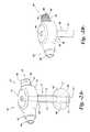
- FIG. 1Ais a perspective view of an exemplary prior art device
- FIG. 1Bis a perspective view of the device of FIG. 1 with the balloon in an expanded state
- FIG. 2Ais a perspective and view of an exemplary enteral feeding catheter assembly incorporating an internal indicator in accordance with aspects of the invention
- FIG. 2Bis a perspective view of the base of the device of FIG. 2A with a change of state of the indicator;
- FIG. 3is a cross-sectional side view of an exemplary enteral feeding catheter assembly incorporating an indicator.
- FIG. 4Ais a perspective view of the base portion of an additional exemplary enteral feeding catheter assembly incorporating an indicator
- FIG. 4Bis a perspective view of the device of FIG. 4A with a change of state of the indicator
- FIG. 5Ais a side view of an alternative exemplary enteral feeding catheter assembly incorporating an indicator
- FIG. 5Bis a side cross-sectional view of the device of FIG. 5A ;
- FIGS. 1A and 1Bare views of a conventional PEG tube device 10 having a base 12 and retainer balloon 13 made of conventional “soft” or elastomeric medical grade silicone in an un-stretched state (i.e., un-inflated condition) at the distal end of a catheter shaft 14 .
- the balloon 13has been stretched by inflation to an inflated operational fill volume.
- the catheter shaft 14is inserted into a stoma in a patient with the balloon 13 in an un-inflated state.
- a syringe(not shown) is inserted into a port 15 in the head 12 and a fluid is injected into the balloon 13 through an inflation valve within the head 12 and an inflation lumen configured in the catheter shaft 14 to inflate the balloon to an operational volume.
- the balloons 13 of conventional PEG devices 10 illustrated in FIGS. 1A and 1Bare made of elastomeric silicone and thus stretch or distend as they expand from the state depicted in FIG. 1A to their operational fill volume depicted in FIG. 1B , which requires a relatively large and continuous change in pressure to overcome the balloon's resistance to stretching.
- a leak in the balloonor in the inflation lumen or inflation valve
- the inflation mediume.g., saline or air
- a balloon catheter device 18 incorporating aspects of the present inventionis illustrated as an enteral feeding device 20 .
- catheter devices 18 according to the inventionare not limited to enteral feeding devices 20 , and that the embodiments illustrated and described herein related to enteral feeding devices 20 are for illustrative purposes only.
- the enteral feeding device 20is configured to provide a discrete visual indication or signal that the volume of fluid in the retention balloon has changed and that the balloon is no longer at its operational fill volume, which may be the result of a leak in the balloon.
- the enteral feeding catheter device 20includes a catheter 26 having a proximal end 28 , a distal end 30 , and catheter walls 32 defining a catheter lumen 34 .
- a base 36is located at the proximal end 28 of the catheter 26 .
- the base 36defines an opening 40 to the catheter lumen 34 and has a first end 42 and a second end 44 .
- the assembly 10includes an inflatable balloon 24 located at a distal end of the catheter.
- the device 20includes an inflation valve 46 located in the base 36 at the first end 42 .
- the inflation valve 46is in fluid communication with the balloon 24 . This may be accomplished, for example, through an inflation lumen 52 ( FIG. 3 ) defined by a portion of the wall 32 of the catheter 26 that extends between a cavity 50 (described in greater detail below) and the balloon 24 , with the cavity 50 being in fluid communication with the inflation valve 46 .
- An external inflation lumen or other configurationsare also contemplated.
- the inflation valvemay desirably be located in the first end 42 of the base.
- the enteral feeding device 20includes an indicator, generally 49 , configured wholly or partially within the base 36 .
- the indicator 49does not utilize movable parts or components within the base 36 or attached to the base 36 .
- the indicator 49does not add to the overall dimensions of the base 36 , particularly to the height or profile of the base 36 relative to a patient's skin, which is particularly desirable to patients.
- the indicator 49is not prone to failure of movable mechanical parts, and does not significantly increase the complexity of the device 20 .
- the indicator 49includes one or more internal cavities 50 defined at any desired location within the base 36 . In FIGS. 2A and 2B , the internal cavity 50 is defined within the second end 44 of the base 36 generally opposite from the inflation valve 46 within the first end 42 .
- a translucent window 54is disposed over the internal cavity 50 such that the internal volume of the cavity 50 is externally viewable through the base 36 , more particularly through the window 54 .
- This window 54may be variously configured.
- the translucent window 54is defined by a translucent cap 60 that is fitted over an opening 55 in the base 36 .
- the opening 55may define all or a portion of the cavity 50 .
- the cap 60may have a contour or radius so as to also define a portion of the cavity 50 , as particularly seen in FIG. 3 .
- the cap 60may be a translucent plate-like member that is bonded to the base 36 over the opening 55 .
- the cap 60 or other member forming the translucent window 54is formed from any suitable translucent medical grade material.
- the translucent window 54need not be clear, but is sufficiently translucent such that a patient or medical staff personnel can readily and visually discern the presence of inflation fluid within the internal cavity 50 through the window 54 , as discussed in greater detail below.
- the internal cavity 50is in fluid communication with the balloon 24 by any suitable means.
- a separate indicator lumen or passage 48is defined in the base 36 between the inflation valve 46 and the cavity 50 , with the cavity 50 being in fluid communication with the balloon 24 via the inflation lumen 52 , as discussed above.
- the cavity 50may be considered as “in series” between the inflation valve 46 and the balloon 24 .
- one or more separate flow passagesmay be defined in the base 36 between the inflation valve 46 and the internal cavity 50 .
- FIG. 5Bdepicts a flow passage 56 disposed directly downstream of the inflation valve 46 , around the circumference of the base 36 , to the internal cavity 50 , as well as a separate inflation lumen 52 between the inflation valve 46 and balloon 24 .
- the inventionalso encompasses a vent configuration, for example within the base 36 , that vents any trapped air within the lumens 48 , 52 , 56 and cavity 50 so that the entire system is pressurized with inflation fluid injected through the inflation valve 46 .
- the internal cavity 50is in fluid communication with the balloon 24 , introduction of a colored (i.e., non-clear) fluid through the inflation valve 46 to inflate the balloon 24 results in the colored fluid 68 ( FIG. 2B ) flowing into the internal cavity 50 and being externally distinguishable through the translucent window 54 , thereby providing an external visual indication of the inflation state of the balloon 24 .
- Visual absence of the fluid 68 within the cavity 50 after placement of the device 20 in a patient and initial inflation of the balloon 24 to its operational fill volumeis an indication that fluid has leaked from the balloon 24 or other component of the device 20 , and that the balloon may not be sufficiently inflated to retain the catheter 26 in the patient's stoma.
- an additional or supplemental indicatormay be provided within the internal cavity 50 , for example a brightly colored ring, or patterned member 51 as indicated in the embodiment of FIG. 4B .
- the colored fluidwould tend to obscure or alter the checkerboard pattern of the member 51 , which provides an additional visually distinguishing indication of the inflation state of the balloon 24 .
- visual absence or change of visual state of the supplemental indicator 51 because of the presence of the colored fluid within the cavity 50is also an indication that the balloon is inflated.
- FIG. 4Adepicts an embodiment of a device 20 wherein multiple cavities 50 and associated translucent windows 54 are defined in the base 36 at different discrete locations on the base 36 .
- FIG. 4Bdepicts an embodiment wherein the cavity 50 and translucent window 54 is defined as a continuous flow passage around the circumference of the base 36 .
- the translucent window 54may be an insert 58 of translucent material that is fitted or bonded to the base 36 over the cavity 50 , as depicted in FIGS. 4A and 4B .
- the portion of the base 36 in which the internal cavity 50 is formed(or the entire base 36 ) may be formed of an inherently translucent material such that the translucent window 54 is defined by the portion of the base 36 overlying the internal cavity 50 , as depicted in FIGS. 5A and 5B .
- the balloon of the inventionmay be a conventional elastomeric balloon, such as the balloon 13 described above with reference to FIGS. 1A and 1B .
- fluid 68will fill the internal cavity 50 and give an externally distinguishable visual indication that the balloon is inflated to at least some degree. If a leak develops in the balloon 13 , the balloon will eventually contract to the state depicted in FIG. 1A , at which point the inflation fluid will also have drained from the internal cavity 50 , thereby generating a visual indication of failure of the balloon 50 .
- the balloon 24 depicted in FIGS. 2A and 2Bis distinguishable from the balloon 13 in FIGS. 1A and 1B .
- the balloon 24has an initial collapsed and folded (“non-distended) state depicted by the phantom line 66 .
- the balloon 24expands to the point in which the material that forms the balloon 24 is smooth and unfolded to an initial distended state, as depicted by the phantom line 62 in FIG. 2A .
- no pressureis required to fill the balloon 24 to this state other than to drive the liquid through the inflation lumen and unfold the balloon 24 because the material forming the balloon is not stretched to reach the initial distended state.
- the balloonis then pressurized and further distended to its operational fill volume.
- This fill volume of the balloon 24is a volume in a range having a lower limit at the volume in which the material that forms the balloon first becomes smooth, unfolded and under a slight pressure but prior to any stretching of the material (state 62 in FIG. 2A ), and an upper limit that is no more than 50% greater in volume than the lower limit (state 64 in FIG. 2A ).
- the predetermined operation fill volumeis a volume in a range with a lower limit at the balloon's transition from a non-distended state to an initial distended state at negligible pressure, and a upper limit that is no more than about 1.5 times (i.e., about fifty percent (50%) greater than) the volume of the balloon at the initial distended state.
- the volume at the lower limit of this range where the pressure of the fluid in the balloon is essentially zerois the “reserve volume”.
- the pressure of fluid in the balloonincreases when the balloon is filled past the reserve volume in a substantially linear relationship with additional increases in the volume of the balloon.
- Various materialsmay used to form the inflatable balloon 24 in the embodiment of FIG. 2A . These materials include, but are not limited to, polyurethane (PU), low-density polyethylene (LDPE), polyvinyl chloride (PVC), polyamide (PA), or polyethylene teraphthalate (PETP). Additionally, copolymer admixtures for modifying the characteristics of the material may be used, for example a low density polyethylene and ethylene-vinylacetate copolymer (LDPE-EVA), or blends of the above mentioned materials (e.g. PU with PVC or PU with PA) would be considered suitable for forming the inflatable balloon having a predetermined fill volume.
- PUpolyurethane
- LDPElow-density polyethylene
- PVCpolyvinyl chloride
- PApolyamide
- PETPpolyethylene teraphthalate
- copolymer admixtures for modifying the characteristics of the materialmay be used, for example a low density polyethylene and ethylene-vinylacetate copoly
- the balloonsmay have thin walls in a range of between about 5 to about 50 micrometers, even more desirably, between about 5 to about 25 micrometers. Suitable materials should possess properties enabling them to be processed into an inflatable retention balloon having micro thin walls. In contrast, conventional silicone balloons have wall thicknesses of about 250 micrometers or even greater.
- An advantage of utilizing such balloons 24 having a predetermined operational fill volume as described aboveis that if there is a leak or breach in the balloon or in another part of the system allowing fluid to escape, the balloon will depressurize to its initial distended state 62 wherein the balloon is at essentially zero pressure yet maintains the reserve volume of fluid, as discussed above.
- the reserve volumeis less than the predetermined operational fill volume and reflects a volume of liquid that is retained in the balloon at about the transition from its non-distended state to its distended state. At the reserve volume, fluid may still be present in the internal cavity 50 . However, exertion on the balloon by the patient will eventually cause loss of the reserve volume, more particularly loss of the fluid from the cavity 50 .
Landscapes
- Health & Medical Sciences (AREA)
- Life Sciences & Earth Sciences (AREA)
- Animal Behavior & Ethology (AREA)
- General Health & Medical Sciences (AREA)
- Public Health (AREA)
- Veterinary Medicine (AREA)
- Pulmonology (AREA)
- Heart & Thoracic Surgery (AREA)
- Gastroenterology & Hepatology (AREA)
- Child & Adolescent Psychology (AREA)
- Biophysics (AREA)
- Engineering & Computer Science (AREA)
- Anesthesiology (AREA)
- Biomedical Technology (AREA)
- Hematology (AREA)
- Media Introduction/Drainage Providing Device (AREA)
- Infusion, Injection, And Reservoir Apparatuses (AREA)
- Medical Preparation Storing Or Oral Administration Devices (AREA)
Abstract
Description
Claims (10)
Priority Applications (8)
| Application Number | Priority Date | Filing Date | Title |
|---|---|---|---|
| US12/977,359US8142394B1 (en) | 2010-12-23 | 2010-12-23 | Enteral feeding catheter device with an indicator |
| MX2013007050AMX338781B (en) | 2010-12-23 | 2011-11-17 | Enteral feeding catheter device with an indicator. |
| PCT/IB2011/055162WO2012085711A1 (en) | 2010-12-23 | 2011-11-17 | Enteral feeding catheter device with an indicator |
| JP2013545538AJP5956459B2 (en) | 2010-12-23 | 2011-11-17 | Enteral feeding catheter device with indicator |
| AU2011346723AAU2011346723B2 (en) | 2010-12-23 | 2011-11-17 | Enteral feeding catheter device with an indicator |
| CA2819443ACA2819443C (en) | 2010-12-23 | 2011-11-17 | Enteral feeding catheter device with an indicator |
| EP11799483.0AEP2654660B1 (en) | 2010-12-23 | 2011-11-17 | Enteral feeding catheter device with an indicator |
| US13/429,799US8672882B2 (en) | 2010-12-23 | 2012-03-26 | Enteral feeding catheter device with an indicator |
Applications Claiming Priority (1)
| Application Number | Priority Date | Filing Date | Title |
|---|---|---|---|
| US12/977,359US8142394B1 (en) | 2010-12-23 | 2010-12-23 | Enteral feeding catheter device with an indicator |
Related Child Applications (1)
| Application Number | Title | Priority Date | Filing Date |
|---|---|---|---|
| US13/429,799DivisionUS8672882B2 (en) | 2010-12-23 | 2012-03-26 | Enteral feeding catheter device with an indicator |
Publications (1)
| Publication Number | Publication Date |
|---|---|
| US8142394B1true US8142394B1 (en) | 2012-03-27 |
Family
ID=45390126
Family Applications (2)
| Application Number | Title | Priority Date | Filing Date |
|---|---|---|---|
| US12/977,359ActiveUS8142394B1 (en) | 2010-12-23 | 2010-12-23 | Enteral feeding catheter device with an indicator |
| US13/429,799ActiveUS8672882B2 (en) | 2010-12-23 | 2012-03-26 | Enteral feeding catheter device with an indicator |
Family Applications After (1)
| Application Number | Title | Priority Date | Filing Date |
|---|---|---|---|
| US13/429,799ActiveUS8672882B2 (en) | 2010-12-23 | 2012-03-26 | Enteral feeding catheter device with an indicator |
Country Status (7)
| Country | Link |
|---|---|
| US (2) | US8142394B1 (en) |
| EP (1) | EP2654660B1 (en) |
| JP (1) | JP5956459B2 (en) |
| AU (1) | AU2011346723B2 (en) |
| CA (1) | CA2819443C (en) |
| MX (1) | MX338781B (en) |
| WO (1) | WO2012085711A1 (en) |
Cited By (14)
| Publication number | Priority date | Publication date | Assignee | Title |
|---|---|---|---|---|
| US20120017897A1 (en)* | 2010-07-20 | 2012-01-26 | Sridhar Ranganathan | Tracheal Tube Cuff Pressure Indicator |
| US20120197192A1 (en)* | 2010-12-23 | 2012-08-02 | Bagwell Alison S | Inflatable Retention System for Enteral Feeding Device |
| US20140058362A1 (en)* | 2012-08-24 | 2014-02-27 | Frank J. Tycast | Medical device for providing port-like access to a mammalian urinary bladder and methods of inserting and utilizing the same |
| CN104000549A (en)* | 2013-02-25 | 2014-08-27 | 广州耀远实业有限公司 | Protecting bush for multiple-cavity endoscope with balloon |
| USD728093S1 (en)* | 2013-02-08 | 2015-04-28 | Xeridiem Medical Devices Inc. | Enteral feeding device |
| US9125801B2 (en) | 2012-09-12 | 2015-09-08 | Cook Medical Technologies, LLC | Visual inflation/deflation indicator for a balloon catheter |
| CN104998338A (en)* | 2015-07-13 | 2015-10-28 | 张敏 | Auxiliary air bag sleeve for gastroscopy |
| US9618130B1 (en)* | 2015-11-29 | 2017-04-11 | Trong D Nguyen | Multi-purpose valve for extending shelf-life using vacuuming or injecting gas |
| USD805194S1 (en)* | 2013-11-25 | 2017-12-12 | Avent, Inc. | Base for enteral feeding device |
| EP3335686A1 (en)* | 2015-07-06 | 2018-06-20 | Werd, LLC | Temporary tubes and a system for placing same in a patient |
| US10588827B2 (en) | 2016-04-06 | 2020-03-17 | Mayo Foundation For Medical Education And Research | Gastrointestinal feeding tubes with enhanced skin surface bumpers |
| US10827659B2 (en) | 2015-11-29 | 2020-11-03 | Trong D Nguyen | Personal microwave autoclave and process using the same for sterilizing N95 masks |
| US11311461B2 (en) | 2017-02-16 | 2022-04-26 | N.V. Nutricia | Gastrostomy device with pressure monitoring |
| WO2023036681A1 (en) | 2021-09-07 | 2023-03-16 | Fresenius Kabi Deutschland Gmbh | Balloon catheter for enteral feeding |
Families Citing this family (12)
| Publication number | Priority date | Publication date | Assignee | Title |
|---|---|---|---|---|
| US8858533B2 (en) | 2004-06-29 | 2014-10-14 | C. R. Bard, Inc. | Methods and systems for providing fluid communication with a gastrostomy tube |
| US8551043B2 (en) | 2006-04-21 | 2013-10-08 | C. R. Bard, Inc. | Feeding device and bolster apparatus and method for making the same |
| EP2451512A1 (en) | 2009-07-07 | 2012-05-16 | C.R. Bard Inc. | Extensible internal bolster for a medical device |
| US9833352B2 (en) | 2011-08-23 | 2017-12-05 | Mayo Foundation For Medical Education And Research | Ostomy devices |
| EP2869798B1 (en)* | 2012-07-03 | 2021-09-01 | Mayo Foundation For Medical Education And Research | Ostomy devices |
| JP7091240B2 (en)* | 2015-09-25 | 2022-06-27 | シー・アール・バード・インコーポレーテッド | Catheter assembly including monitoring capability |
| EP4368156A3 (en) | 2017-11-09 | 2024-11-06 | ConvaTec Technologies Inc. | Ostomy monitoring system and method |
| WO2020055722A1 (en)* | 2018-09-10 | 2020-03-19 | The Regents Of The University Of Michigan | Self-inflating anorectal expulsion device |
| USD893514S1 (en) | 2018-11-08 | 2020-08-18 | 11 Health And Technologies Limited | Display screen or portion thereof with graphical user interface |
| US12208064B2 (en)* | 2020-04-30 | 2025-01-28 | Avent, Inc. | Polyurethane bonding skeleton for feeding tube device |
| US12357494B2 (en) | 2020-10-15 | 2025-07-15 | Convatec Technologies Inc. | Ostomy systems and methods |
| EP4460270A1 (en)* | 2022-01-09 | 2024-11-13 | Craig F. Beyer | Internal condom method and device |
Citations (44)
| Publication number | Priority date | Publication date | Assignee | Title |
|---|---|---|---|---|
| US3630198A (en)* | 1969-06-23 | 1971-12-28 | Henkin Melvyn Lane | Catheter placement device |
| US3642005A (en) | 1970-02-11 | 1972-02-15 | Gerald E Mcginnis | Endotracheal tube with inflatable cuff |
| US3780693A (en) | 1972-05-15 | 1973-12-25 | E Parr | Visible fluid pressure indicator |
| US4245639A (en)* | 1979-04-30 | 1981-01-20 | C. R. Bard, Inc. | Self-inflating urinary catheter |
| US4266550A (en) | 1977-01-10 | 1981-05-12 | Bruner James D | Pressure indicators for inflatable cuff-type catheters |
| US4384584A (en)* | 1981-10-28 | 1983-05-24 | Chen Allen S | Method and means for esophageal feeding |
| US4502490A (en) | 1980-10-28 | 1985-03-05 | Antec Systems Limited | Patient monitoring equipment, probe for use therewith, and method of measuring anesthesia based on oesophagal contractions |
| US4522194A (en) | 1983-02-18 | 1985-06-11 | Baylor College Of Medicine | Method and an apparatus for intra-aortic balloon monitoring and leak detection |
| US5103817A (en) | 1990-07-20 | 1992-04-14 | Xomed-Treace Inc. | Automatic dye dispersant for endotracheal tubes and catheters |
| US5201755A (en) | 1990-09-11 | 1993-04-13 | Datascope Investment Corp. | Method and apparatus for early detection of leakage and failure of a balloon membrane of a balloon catheter |
| US5218970A (en) | 1990-12-05 | 1993-06-15 | Smiths Industries Public Limited Company | Tracheal tube cuff pressure monitor |
| US5496311A (en) | 1988-10-28 | 1996-03-05 | Boston Scientific Corporation | Physiologic low stress angioplasty |
| US5792070A (en) | 1996-08-30 | 1998-08-11 | Urologix, Inc. | Rectal thermosensing unit |
| US6004305A (en)* | 1996-05-03 | 1999-12-21 | Spectrum Medsystems, Inc. | Drainage catheter assembly |
| US6082361A (en)* | 1997-09-12 | 2000-07-04 | Morejon; Orlando | Endotracheal tube cleaning apparatus |
| US20020045854A1 (en)* | 2000-10-16 | 2002-04-18 | Probitis Pharma, S.A. | Apparatus for the inflation and deflation of balloon catheters and a method for its use |
| US20020115962A1 (en)* | 2001-02-02 | 2002-08-22 | Biocompatibles Limited | Balloon catheter inflation |
| US6536260B2 (en) | 1999-06-24 | 2003-03-25 | Datascope Investment Corp. | Balloon catheter leak detection method and apparatus |
| WO2003101372A1 (en) | 2002-05-28 | 2003-12-11 | Sherwood Services, Ag | External inflation indicator for a low profile gastrostomy tube |
| US6732734B2 (en) | 2001-04-27 | 2004-05-11 | Kuraray Co., Ltd. | Pilot balloon for balloon catheters |
| US20040097813A1 (en) | 2002-11-19 | 2004-05-20 | Jonathan Williams | Method and device for correcting in -vivo sensor drift |
| US20040106899A1 (en) | 2002-11-30 | 2004-06-03 | Mcmichael Donald J. | Gastric balloon catheter with improved balloon orientation |
| US20040106901A1 (en)* | 2002-11-30 | 2004-06-03 | Letson William W. | Catheter having a balloon member invertedly attached thereto |
| US20040267195A1 (en) | 2003-06-24 | 2004-12-30 | Arnoldo Currlin | Catheter balloon having visible marker |
| US6916307B2 (en) | 1998-02-12 | 2005-07-12 | Kimberly-Clark Worldwide, Inc. | Catheter with distally distending balloon |
| US20050197667A1 (en)* | 2004-03-02 | 2005-09-08 | Scimed Life Systems, Inc. | Occlusion balloon catheter with external inflation lumen |
| US7018359B2 (en) | 1999-06-25 | 2006-03-28 | Koken Co., Ltd. | Inner pressure indicator of cuff |
| US20060271088A1 (en)* | 2005-05-02 | 2006-11-30 | Almuhannad Alfrhan | Percutaneous intragastric balloon device and method |
| US20070010787A1 (en)* | 2005-07-07 | 2007-01-11 | Hackett Steven S | Embolic protection device and methods of use |
| US7195612B2 (en) | 2005-03-31 | 2007-03-27 | Gordis Corporation | Esophageal balloon catheter with visual marker |
| US20070208301A1 (en)* | 2005-06-10 | 2007-09-06 | Acclarent, Inc. | Catheters with non-removable guide members useable for treatment of sinusitis |
| US7383736B2 (en) | 2002-05-24 | 2008-06-10 | Ultimate Medical Pty Ltd | Device and method for pressure indication |
| US20080146993A1 (en) | 2006-12-19 | 2008-06-19 | Cytyc Corporation | Systems and Methods for Drug Infusion with Feedback Control |
| US7404329B2 (en) | 2004-12-08 | 2008-07-29 | Engineered Medical Systems, Inc. | Pressure gauge for use with an airway lumen |
| US20080208240A1 (en) | 2005-08-11 | 2008-08-28 | Stimplant Ltd. | Implantable Device For Obesity Prevention |
| US20080228138A1 (en) | 2005-03-31 | 2008-09-18 | Van Sloten Leonard A | Catheter with balloon having visual marker |
| US20090312701A1 (en)* | 2005-06-17 | 2009-12-17 | Kimberly-Clark Worldwide, Inc. | Device for Gastric Feeding and Drainage Via an Artificial Stoma |
| US20100185155A1 (en)* | 2009-01-19 | 2010-07-22 | Mcmichael Donald J | Enteral Feeding Assembly With Obturator |
| US20100185159A1 (en)* | 2009-01-22 | 2010-07-22 | Bagwell Alison S | Enteral Feeding Assembly With Lock Assembly |
| US20100217185A1 (en) | 2007-05-21 | 2010-08-26 | Gad Terliuc | Catheter including a bendable portion |
| US20100228192A1 (en) | 2007-06-27 | 2010-09-09 | Flip Technologies Limited | device and a system for use in a procedure for improving a sealing function of a sphincter and a method for improving the sealing function of a sphincter |
| US20100312181A1 (en) | 2007-12-20 | 2010-12-09 | Flip Technologies Limited | Method and apparatus for determining volume of a vessel |
| US20110082444A1 (en)* | 2005-01-26 | 2011-04-07 | Mayback Gregory L | Zero-Pressure Balloon Catheter and Method for Using the Catheter |
| US20110152762A1 (en)* | 2009-12-23 | 2011-06-23 | Hershey Adrienne A | Enteral Feeding Catheter Assembly Incorporating An Indicator |
Family Cites Families (8)
| Publication number | Priority date | Publication date | Assignee | Title |
|---|---|---|---|---|
| US3409016A (en)* | 1964-04-08 | 1968-11-05 | Selflate Corp | Disposable cartridge for inflating bag catheters |
| US3915171A (en) | 1974-06-06 | 1975-10-28 | Dennis William Shermeta | Gastrostomy tube |
| US4134407A (en)* | 1977-03-25 | 1979-01-16 | Elam James O | External pressure-volume monitor for endotracheal cuff |
| US4315513A (en) | 1980-03-10 | 1982-02-16 | Nawash Michael S | Gastrostomy and other percutaneous transport tubes |
| US4944732A (en) | 1988-08-15 | 1990-07-31 | Sandoz Nutrition Corporation | Gastrostomy feeding port |
| US5484420A (en) | 1992-07-09 | 1996-01-16 | Wilson-Cook Medical Inc. | Retention bolsters for percutaneous catheters |
| DE4237978C1 (en)* | 1992-11-11 | 1994-02-24 | Braun Melsungen Ag | One-trip pressure indicator for medical device - has housing divided by membrane into pressure chamber and equalisation chamber containing display fluid for circular display channel |
| AU2010226598A1 (en)* | 2009-03-17 | 2011-10-27 | Pivot Medical, Inc. | Method and apparatus for distracting a joint, including the provision and use of a novel joint-spacing balloon catheter and a novel inflatable perineal post |
- 2010
- 2010-12-23USUS12/977,359patent/US8142394B1/enactiveActive
- 2011
- 2011-11-17WOPCT/IB2011/055162patent/WO2012085711A1/enactiveApplication Filing
- 2011-11-17JPJP2013545538Apatent/JP5956459B2/enactiveActive
- 2011-11-17AUAU2011346723Apatent/AU2011346723B2/enactiveActive
- 2011-11-17CACA2819443Apatent/CA2819443C/enactiveActive
- 2011-11-17MXMX2013007050Apatent/MX338781B/enactiveIP Right Grant
- 2011-11-17EPEP11799483.0Apatent/EP2654660B1/enactiveActive
- 2012
- 2012-03-26USUS13/429,799patent/US8672882B2/enactiveActive
Patent Citations (45)
| Publication number | Priority date | Publication date | Assignee | Title |
|---|---|---|---|---|
| US3630198A (en)* | 1969-06-23 | 1971-12-28 | Henkin Melvyn Lane | Catheter placement device |
| US3642005A (en) | 1970-02-11 | 1972-02-15 | Gerald E Mcginnis | Endotracheal tube with inflatable cuff |
| US3780693A (en) | 1972-05-15 | 1973-12-25 | E Parr | Visible fluid pressure indicator |
| US4266550A (en) | 1977-01-10 | 1981-05-12 | Bruner James D | Pressure indicators for inflatable cuff-type catheters |
| US4245639A (en)* | 1979-04-30 | 1981-01-20 | C. R. Bard, Inc. | Self-inflating urinary catheter |
| US4502490A (en) | 1980-10-28 | 1985-03-05 | Antec Systems Limited | Patient monitoring equipment, probe for use therewith, and method of measuring anesthesia based on oesophagal contractions |
| US4384584A (en)* | 1981-10-28 | 1983-05-24 | Chen Allen S | Method and means for esophageal feeding |
| US4522194A (en) | 1983-02-18 | 1985-06-11 | Baylor College Of Medicine | Method and an apparatus for intra-aortic balloon monitoring and leak detection |
| US5496311A (en) | 1988-10-28 | 1996-03-05 | Boston Scientific Corporation | Physiologic low stress angioplasty |
| US5103817A (en) | 1990-07-20 | 1992-04-14 | Xomed-Treace Inc. | Automatic dye dispersant for endotracheal tubes and catheters |
| US5201755A (en) | 1990-09-11 | 1993-04-13 | Datascope Investment Corp. | Method and apparatus for early detection of leakage and failure of a balloon membrane of a balloon catheter |
| US5218970A (en) | 1990-12-05 | 1993-06-15 | Smiths Industries Public Limited Company | Tracheal tube cuff pressure monitor |
| US6004305A (en)* | 1996-05-03 | 1999-12-21 | Spectrum Medsystems, Inc. | Drainage catheter assembly |
| US5792070A (en) | 1996-08-30 | 1998-08-11 | Urologix, Inc. | Rectal thermosensing unit |
| US6082361A (en)* | 1997-09-12 | 2000-07-04 | Morejon; Orlando | Endotracheal tube cleaning apparatus |
| US6916307B2 (en) | 1998-02-12 | 2005-07-12 | Kimberly-Clark Worldwide, Inc. | Catheter with distally distending balloon |
| US6536260B2 (en) | 1999-06-24 | 2003-03-25 | Datascope Investment Corp. | Balloon catheter leak detection method and apparatus |
| US7018359B2 (en) | 1999-06-25 | 2006-03-28 | Koken Co., Ltd. | Inner pressure indicator of cuff |
| US20020045854A1 (en)* | 2000-10-16 | 2002-04-18 | Probitis Pharma, S.A. | Apparatus for the inflation and deflation of balloon catheters and a method for its use |
| US20020115962A1 (en)* | 2001-02-02 | 2002-08-22 | Biocompatibles Limited | Balloon catheter inflation |
| US6732734B2 (en) | 2001-04-27 | 2004-05-11 | Kuraray Co., Ltd. | Pilot balloon for balloon catheters |
| US7383736B2 (en) | 2002-05-24 | 2008-06-10 | Ultimate Medical Pty Ltd | Device and method for pressure indication |
| WO2003101372A1 (en) | 2002-05-28 | 2003-12-11 | Sherwood Services, Ag | External inflation indicator for a low profile gastrostomy tube |
| US6878130B2 (en) | 2002-05-28 | 2005-04-12 | Sherwood Services Ag | External inflation indicator for a low profile gastrostomy tube |
| US20040097813A1 (en) | 2002-11-19 | 2004-05-20 | Jonathan Williams | Method and device for correcting in -vivo sensor drift |
| US20040106901A1 (en)* | 2002-11-30 | 2004-06-03 | Letson William W. | Catheter having a balloon member invertedly attached thereto |
| US20040106899A1 (en) | 2002-11-30 | 2004-06-03 | Mcmichael Donald J. | Gastric balloon catheter with improved balloon orientation |
| US20040267195A1 (en) | 2003-06-24 | 2004-12-30 | Arnoldo Currlin | Catheter balloon having visible marker |
| US20050197667A1 (en)* | 2004-03-02 | 2005-09-08 | Scimed Life Systems, Inc. | Occlusion balloon catheter with external inflation lumen |
| US7404329B2 (en) | 2004-12-08 | 2008-07-29 | Engineered Medical Systems, Inc. | Pressure gauge for use with an airway lumen |
| US20110082444A1 (en)* | 2005-01-26 | 2011-04-07 | Mayback Gregory L | Zero-Pressure Balloon Catheter and Method for Using the Catheter |
| US7195612B2 (en) | 2005-03-31 | 2007-03-27 | Gordis Corporation | Esophageal balloon catheter with visual marker |
| US20080228138A1 (en) | 2005-03-31 | 2008-09-18 | Van Sloten Leonard A | Catheter with balloon having visual marker |
| US20060271088A1 (en)* | 2005-05-02 | 2006-11-30 | Almuhannad Alfrhan | Percutaneous intragastric balloon device and method |
| US20070208301A1 (en)* | 2005-06-10 | 2007-09-06 | Acclarent, Inc. | Catheters with non-removable guide members useable for treatment of sinusitis |
| US20090312701A1 (en)* | 2005-06-17 | 2009-12-17 | Kimberly-Clark Worldwide, Inc. | Device for Gastric Feeding and Drainage Via an Artificial Stoma |
| US20070010787A1 (en)* | 2005-07-07 | 2007-01-11 | Hackett Steven S | Embolic protection device and methods of use |
| US20080208240A1 (en) | 2005-08-11 | 2008-08-28 | Stimplant Ltd. | Implantable Device For Obesity Prevention |
| US20080146993A1 (en) | 2006-12-19 | 2008-06-19 | Cytyc Corporation | Systems and Methods for Drug Infusion with Feedback Control |
| US20100217185A1 (en) | 2007-05-21 | 2010-08-26 | Gad Terliuc | Catheter including a bendable portion |
| US20100228192A1 (en) | 2007-06-27 | 2010-09-09 | Flip Technologies Limited | device and a system for use in a procedure for improving a sealing function of a sphincter and a method for improving the sealing function of a sphincter |
| US20100312181A1 (en) | 2007-12-20 | 2010-12-09 | Flip Technologies Limited | Method and apparatus for determining volume of a vessel |
| US20100185155A1 (en)* | 2009-01-19 | 2010-07-22 | Mcmichael Donald J | Enteral Feeding Assembly With Obturator |
| US20100185159A1 (en)* | 2009-01-22 | 2010-07-22 | Bagwell Alison S | Enteral Feeding Assembly With Lock Assembly |
| US20110152762A1 (en)* | 2009-12-23 | 2011-06-23 | Hershey Adrienne A | Enteral Feeding Catheter Assembly Incorporating An Indicator |
Non-Patent Citations (1)
| Title |
|---|
| Co-Pending U.S. Appl. No. 12/645,553, filed Dec. 23, 2009. |
Cited By (21)
| Publication number | Priority date | Publication date | Assignee | Title |
|---|---|---|---|---|
| US20120017897A1 (en)* | 2010-07-20 | 2012-01-26 | Sridhar Ranganathan | Tracheal Tube Cuff Pressure Indicator |
| US9149415B2 (en) | 2010-12-23 | 2015-10-06 | Avent, Inc. | Inflatable retention system for an enteral feeding device |
| US20120197192A1 (en)* | 2010-12-23 | 2012-08-02 | Bagwell Alison S | Inflatable Retention System for Enteral Feeding Device |
| US8475406B2 (en)* | 2010-12-23 | 2013-07-02 | Kimberly-Clark Worldwide, Inc. | Inflatable retention system for enteral feeding device |
| US9155684B2 (en) | 2010-12-23 | 2015-10-13 | Avent, Inc. | Inflatable retention system for an enteral feeding device |
| US20140058362A1 (en)* | 2012-08-24 | 2014-02-27 | Frank J. Tycast | Medical device for providing port-like access to a mammalian urinary bladder and methods of inserting and utilizing the same |
| US8870852B2 (en)* | 2012-08-24 | 2014-10-28 | Tycast Technologies, Llc | Medical device for providing port-like access to a mammalian urinary bladder and methods of inserting and utilizing the same |
| US9125801B2 (en) | 2012-09-12 | 2015-09-08 | Cook Medical Technologies, LLC | Visual inflation/deflation indicator for a balloon catheter |
| USD728093S1 (en)* | 2013-02-08 | 2015-04-28 | Xeridiem Medical Devices Inc. | Enteral feeding device |
| CN104000549A (en)* | 2013-02-25 | 2014-08-27 | 广州耀远实业有限公司 | Protecting bush for multiple-cavity endoscope with balloon |
| CN104000549B (en)* | 2013-02-25 | 2016-02-10 | 广州耀远实业有限公司 | A kind of band saccule multicavity road endoscope sheath |
| USD805194S1 (en)* | 2013-11-25 | 2017-12-12 | Avent, Inc. | Base for enteral feeding device |
| EP3335686A1 (en)* | 2015-07-06 | 2018-06-20 | Werd, LLC | Temporary tubes and a system for placing same in a patient |
| US11000452B2 (en) | 2015-07-06 | 2021-05-11 | Werd, Llc | Temporary tubes and a system for placing same in a patient |
| CN104998338A (en)* | 2015-07-13 | 2015-10-28 | 张敏 | Auxiliary air bag sleeve for gastroscopy |
| US10827659B2 (en) | 2015-11-29 | 2020-11-03 | Trong D Nguyen | Personal microwave autoclave and process using the same for sterilizing N95 masks |
| US9618130B1 (en)* | 2015-11-29 | 2017-04-11 | Trong D Nguyen | Multi-purpose valve for extending shelf-life using vacuuming or injecting gas |
| US10588827B2 (en) | 2016-04-06 | 2020-03-17 | Mayo Foundation For Medical Education And Research | Gastrointestinal feeding tubes with enhanced skin surface bumpers |
| US11285085B2 (en) | 2016-04-06 | 2022-03-29 | Mayo Foundation For Medical Education And Research | Gastrointestinal feeding tubes with enhanced skin surface bumpers |
| US11311461B2 (en) | 2017-02-16 | 2022-04-26 | N.V. Nutricia | Gastrostomy device with pressure monitoring |
| WO2023036681A1 (en) | 2021-09-07 | 2023-03-16 | Fresenius Kabi Deutschland Gmbh | Balloon catheter for enteral feeding |
Also Published As
| Publication number | Publication date |
|---|---|
| AU2011346723B2 (en) | 2015-09-03 |
| CA2819443A1 (en) | 2012-06-28 |
| WO2012085711A1 (en) | 2012-06-28 |
| MX338781B (en) | 2016-05-02 |
| MX2013007050A (en) | 2013-07-29 |
| CA2819443C (en) | 2018-09-18 |
| US8672882B2 (en) | 2014-03-18 |
| JP5956459B2 (en) | 2016-07-27 |
| US20120245519A1 (en) | 2012-09-27 |
| EP2654660B1 (en) | 2016-02-03 |
| EP2654660A1 (en) | 2013-10-30 |
| AU2011346723A1 (en) | 2013-06-06 |
| JP2014502892A (en) | 2014-02-06 |
Similar Documents
| Publication | Publication Date | Title |
|---|---|---|
| US8142394B1 (en) | Enteral feeding catheter device with an indicator | |
| US10085922B2 (en) | Enteral feeding catheter assembly incorporating an indicator | |
| US4134407A (en) | External pressure-volume monitor for endotracheal cuff | |
| US8177742B1 (en) | Inflatable retention system for an enteral feeding device | |
| EP3893974B1 (en) | Medico-surgical tube arrangements | |
| US20120017897A1 (en) | Tracheal Tube Cuff Pressure Indicator | |
| CN217661033U (en) | Trachea cannula capable of observing pressure of air bag | |
| AU2015202407B2 (en) | Enteral feeding catheter assembly incorporating an indicator |
Legal Events
| Date | Code | Title | Description |
|---|---|---|---|
| AS | Assignment | Owner name:KIMBERLY-CLARK WORLDWIDE, INC., WISCONSIN Free format text:ASSIGNMENT OF ASSIGNORS INTEREST;ASSIGNORS:ROTELLA, JOHN A.;HERSHEY, ADRIENNE A.;MCMICHAEL, DONALD J.;REEL/FRAME:025565/0741 Effective date:20101222 | |
| STCF | Information on status: patent grant | Free format text:PATENTED CASE | |
| AS | Assignment | Owner name:AVENT, INC., GEORGIA Free format text:ASSIGNMENT OF ASSIGNORS INTEREST;ASSIGNOR:KIMBERLY-CLARK WORLDWIDE, INC.;REEL/FRAME:034753/0001 Effective date:20141030 | |
| AS | Assignment | Owner name:MORGAN STANLEY SENIOR FUNDING, INC., NEW YORK Free format text:SECURITY INTEREST;ASSIGNOR:AVENT, INC.;REEL/FRAME:035375/0867 Effective date:20150227 | |
| FPAY | Fee payment | Year of fee payment:4 | |
| AS | Assignment | Owner name:CITIBANK, N.A., NEW YORK Free format text:INTELLECTUAL PROPERTY SECURITY INTEREST ASSIGNMENT AGREEMENT;ASSIGNOR:MORGAN STANLEY SENIOR FUNDING, INC.;REEL/FRAME:048173/0137 Effective date:20181029 | |
| MAFP | Maintenance fee payment | Free format text:PAYMENT OF MAINTENANCE FEE, 8TH YEAR, LARGE ENTITY (ORIGINAL EVENT CODE: M1552); ENTITY STATUS OF PATENT OWNER: LARGE ENTITY Year of fee payment:8 | |
| AS | Assignment | Owner name:JPMORGAN CHASE BANK, N.A., AS ADMINISTRATIVE AGENT, ILLINOIS Free format text:SECURITY INTEREST;ASSIGNOR:AVENT, INC.;REEL/FRAME:060441/0445 Effective date:20220624 | |
| AS | Assignment | Owner name:AVANOS MEDICAL SALES, LLC, GEORGIA Free format text:RELEASE BY SECURED PARTY;ASSIGNOR:CITIBANK, N.A.;REEL/FRAME:060557/0062 Effective date:20220624 Owner name:AVENT, INC., GEORGIA Free format text:RELEASE BY SECURED PARTY;ASSIGNOR:CITIBANK, N.A.;REEL/FRAME:060557/0062 Effective date:20220624 | |
| MAFP | Maintenance fee payment | Free format text:PAYMENT OF MAINTENANCE FEE, 12TH YEAR, LARGE ENTITY (ORIGINAL EVENT CODE: M1553); ENTITY STATUS OF PATENT OWNER: LARGE ENTITY Year of fee payment:12 |