US8142382B2 - Vibration dampening material and method of making same - Google Patents
Vibration dampening material and method of making sameDownload PDFInfo
- Publication number
- US8142382B2 US8142382B2US10/958,745US95874504AUS8142382B2US 8142382 B2US8142382 B2US 8142382B2US 95874504 AUS95874504 AUS 95874504AUS 8142382 B2US8142382 B2US 8142382B2
- Authority
- US
- United States
- Prior art keywords
- tape
- support structure
- elastomer layer
- athletic
- layer
- Prior art date
- Legal status (The legal status is an assumption and is not a legal conclusion. Google has not performed a legal analysis and makes no representation as to the accuracy of the status listed.)
- Active, expires
Links
Images


Classifications
- A—HUMAN NECESSITIES
- A61—MEDICAL OR VETERINARY SCIENCE; HYGIENE
- A61F—FILTERS IMPLANTABLE INTO BLOOD VESSELS; PROSTHESES; DEVICES PROVIDING PATENCY TO, OR PREVENTING COLLAPSING OF, TUBULAR STRUCTURES OF THE BODY, e.g. STENTS; ORTHOPAEDIC, NURSING OR CONTRACEPTIVE DEVICES; FOMENTATION; TREATMENT OR PROTECTION OF EYES OR EARS; BANDAGES, DRESSINGS OR ABSORBENT PADS; FIRST-AID KITS
- A61F13/00—Bandages or dressings; Absorbent pads
- A61F13/02—Adhesive bandages or dressings
- A—HUMAN NECESSITIES
- A63—SPORTS; GAMES; AMUSEMENTS
- A63B—APPARATUS FOR PHYSICAL TRAINING, GYMNASTICS, SWIMMING, CLIMBING, OR FENCING; BALL GAMES; TRAINING EQUIPMENT
- A63B59/00—Bats, rackets, or the like, not covered by groups A63B49/00 - A63B57/00
- A63B59/50—Substantially rod-shaped bats for hitting a ball in the air, e.g. for baseball
- A—HUMAN NECESSITIES
- A63—SPORTS; GAMES; AMUSEMENTS
- A63B—APPARATUS FOR PHYSICAL TRAINING, GYMNASTICS, SWIMMING, CLIMBING, OR FENCING; BALL GAMES; TRAINING EQUIPMENT
- A63B60/00—Details or accessories of golf clubs, bats, rackets or the like
- A63B60/06—Handles
- A—HUMAN NECESSITIES
- A63—SPORTS; GAMES; AMUSEMENTS
- A63B—APPARATUS FOR PHYSICAL TRAINING, GYMNASTICS, SWIMMING, CLIMBING, OR FENCING; BALL GAMES; TRAINING EQUIPMENT
- A63B60/00—Details or accessories of golf clubs, bats, rackets or the like
- A63B60/06—Handles
- A63B60/08—Handles characterised by the material
- A—HUMAN NECESSITIES
- A63—SPORTS; GAMES; AMUSEMENTS
- A63B—APPARATUS FOR PHYSICAL TRAINING, GYMNASTICS, SWIMMING, CLIMBING, OR FENCING; BALL GAMES; TRAINING EQUIPMENT
- A63B60/00—Details or accessories of golf clubs, bats, rackets or the like
- A63B60/06—Handles
- A63B60/10—Handles with means for indicating correct holding positions
- A—HUMAN NECESSITIES
- A63—SPORTS; GAMES; AMUSEMENTS
- A63B—APPARATUS FOR PHYSICAL TRAINING, GYMNASTICS, SWIMMING, CLIMBING, OR FENCING; BALL GAMES; TRAINING EQUIPMENT
- A63B60/00—Details or accessories of golf clubs, bats, rackets or the like
- A63B60/54—Details or accessories of golf clubs, bats, rackets or the like with means for damping vibrations
- B—PERFORMING OPERATIONS; TRANSPORTING
- B25—HAND TOOLS; PORTABLE POWER-DRIVEN TOOLS; MANIPULATORS
- B25G—HANDLES FOR HAND IMPLEMENTS
- B25G1/00—Handle constructions
- B25G1/01—Shock-absorbing means
- B—PERFORMING OPERATIONS; TRANSPORTING
- B25—HAND TOOLS; PORTABLE POWER-DRIVEN TOOLS; MANIPULATORS
- B25G—HANDLES FOR HAND IMPLEMENTS
- B25G1/00—Handle constructions
- B25G1/10—Handle constructions characterised by material or shape
- B—PERFORMING OPERATIONS; TRANSPORTING
- B32—LAYERED PRODUCTS
- B32B—LAYERED PRODUCTS, i.e. PRODUCTS BUILT-UP OF STRATA OF FLAT OR NON-FLAT, e.g. CELLULAR OR HONEYCOMB, FORM
- B32B27/00—Layered products comprising a layer of synthetic resin
- B32B27/12—Layered products comprising a layer of synthetic resin next to a fibrous or filamentary layer
- B—PERFORMING OPERATIONS; TRANSPORTING
- B32—LAYERED PRODUCTS
- B32B—LAYERED PRODUCTS, i.e. PRODUCTS BUILT-UP OF STRATA OF FLAT OR NON-FLAT, e.g. CELLULAR OR HONEYCOMB, FORM
- B32B5/00—Layered products characterised by the non- homogeneity or physical structure, i.e. comprising a fibrous, filamentary, particulate or foam layer; Layered products characterised by having a layer differing constitutionally or physically in different parts
- B32B5/02—Layered products characterised by the non- homogeneity or physical structure, i.e. comprising a fibrous, filamentary, particulate or foam layer; Layered products characterised by having a layer differing constitutionally or physically in different parts characterised by structural features of a fibrous or filamentary layer
- B32B5/024—Woven fabric
- B—PERFORMING OPERATIONS; TRANSPORTING
- B32—LAYERED PRODUCTS
- B32B—LAYERED PRODUCTS, i.e. PRODUCTS BUILT-UP OF STRATA OF FLAT OR NON-FLAT, e.g. CELLULAR OR HONEYCOMB, FORM
- B32B7/00—Layered products characterised by the relation between layers; Layered products characterised by the relative orientation of features between layers, or by the relative values of a measurable parameter between layers, i.e. products comprising layers having different physical, chemical or physicochemical properties; Layered products characterised by the interconnection of layers
- B32B7/02—Physical, chemical or physicochemical properties
- B32B7/022—Mechanical properties
- A—HUMAN NECESSITIES
- A63—SPORTS; GAMES; AMUSEMENTS
- A63B—APPARATUS FOR PHYSICAL TRAINING, GYMNASTICS, SWIMMING, CLIMBING, OR FENCING; BALL GAMES; TRAINING EQUIPMENT
- A63B59/00—Bats, rackets, or the like, not covered by groups A63B49/00 - A63B57/00
- A63B59/50—Substantially rod-shaped bats for hitting a ball in the air, e.g. for baseball
- A63B59/58—Substantially rod-shaped bats for hitting a ball in the air, e.g. for baseball characterised by the shape
- A63B2059/581—Substantially rod-shaped bats for hitting a ball in the air, e.g. for baseball characterised by the shape with a continuously tapered barrel
- A—HUMAN NECESSITIES
- A63—SPORTS; GAMES; AMUSEMENTS
- A63B—APPARATUS FOR PHYSICAL TRAINING, GYMNASTICS, SWIMMING, CLIMBING, OR FENCING; BALL GAMES; TRAINING EQUIPMENT
- A63B2102/00—Application of clubs, bats, rackets or the like to the sporting activity ; particular sports involving the use of balls and clubs, bats, rackets, or the like
- A63B2102/18—Baseball, rounders or similar games
- A—HUMAN NECESSITIES
- A63—SPORTS; GAMES; AMUSEMENTS
- A63B—APPARATUS FOR PHYSICAL TRAINING, GYMNASTICS, SWIMMING, CLIMBING, OR FENCING; BALL GAMES; TRAINING EQUIPMENT
- A63B71/00—Games or sports accessories not covered in groups A63B1/00 - A63B69/00
- A63B71/08—Body-protectors for players or sportsmen, i.e. body-protecting accessories affording protection of body parts against blows or collisions
- B—PERFORMING OPERATIONS; TRANSPORTING
- B32—LAYERED PRODUCTS
- B32B—LAYERED PRODUCTS, i.e. PRODUCTS BUILT-UP OF STRATA OF FLAT OR NON-FLAT, e.g. CELLULAR OR HONEYCOMB, FORM
- B32B2307/00—Properties of the layers or laminate
- B32B2307/50—Properties of the layers or laminate having particular mechanical properties
- B32B2307/536—Hardness
- B—PERFORMING OPERATIONS; TRANSPORTING
- B32—LAYERED PRODUCTS
- B32B—LAYERED PRODUCTS, i.e. PRODUCTS BUILT-UP OF STRATA OF FLAT OR NON-FLAT, e.g. CELLULAR OR HONEYCOMB, FORM
- B32B2307/00—Properties of the layers or laminate
- B32B2307/50—Properties of the layers or laminate having particular mechanical properties
- B32B2307/56—Damping, energy absorption
- B—PERFORMING OPERATIONS; TRANSPORTING
- B32—LAYERED PRODUCTS
- B32B—LAYERED PRODUCTS, i.e. PRODUCTS BUILT-UP OF STRATA OF FLAT OR NON-FLAT, e.g. CELLULAR OR HONEYCOMB, FORM
- B32B2307/00—Properties of the layers or laminate
- B32B2307/70—Other properties
- B32B2307/744—Non-slip, anti-slip
- B—PERFORMING OPERATIONS; TRANSPORTING
- B32—LAYERED PRODUCTS
- B32B—LAYERED PRODUCTS, i.e. PRODUCTS BUILT-UP OF STRATA OF FLAT OR NON-FLAT, e.g. CELLULAR OR HONEYCOMB, FORM
- B32B2535/00—Medical equipment, e.g. bandage, prostheses or catheter
- Y—GENERAL TAGGING OF NEW TECHNOLOGICAL DEVELOPMENTS; GENERAL TAGGING OF CROSS-SECTIONAL TECHNOLOGIES SPANNING OVER SEVERAL SECTIONS OF THE IPC; TECHNICAL SUBJECTS COVERED BY FORMER USPC CROSS-REFERENCE ART COLLECTIONS [XRACs] AND DIGESTS
- Y10—TECHNICAL SUBJECTS COVERED BY FORMER USPC
- Y10T—TECHNICAL SUBJECTS COVERED BY FORMER US CLASSIFICATION
- Y10T428/00—Stock material or miscellaneous articles
- Y10T428/249921—Web or sheet containing structurally defined element or component
- Y10T428/249924—Noninterengaged fiber-containing paper-free web or sheet which is not of specified porosity
- Y10T428/249927—Fiber embedded in a metal matrix
- Y—GENERAL TAGGING OF NEW TECHNOLOGICAL DEVELOPMENTS; GENERAL TAGGING OF CROSS-SECTIONAL TECHNOLOGIES SPANNING OVER SEVERAL SECTIONS OF THE IPC; TECHNICAL SUBJECTS COVERED BY FORMER USPC CROSS-REFERENCE ART COLLECTIONS [XRACs] AND DIGESTS
- Y10—TECHNICAL SUBJECTS COVERED BY FORMER USPC
- Y10T—TECHNICAL SUBJECTS COVERED BY FORMER US CLASSIFICATION
- Y10T428/00—Stock material or miscellaneous articles
- Y10T428/249921—Web or sheet containing structurally defined element or component
- Y10T428/249924—Noninterengaged fiber-containing paper-free web or sheet which is not of specified porosity
- Y10T428/249928—Fiber embedded in a ceramic, glass, or carbon matrix
- Y—GENERAL TAGGING OF NEW TECHNOLOGICAL DEVELOPMENTS; GENERAL TAGGING OF CROSS-SECTIONAL TECHNOLOGIES SPANNING OVER SEVERAL SECTIONS OF THE IPC; TECHNICAL SUBJECTS COVERED BY FORMER USPC CROSS-REFERENCE ART COLLECTIONS [XRACs] AND DIGESTS
- Y10—TECHNICAL SUBJECTS COVERED BY FORMER USPC
- Y10T—TECHNICAL SUBJECTS COVERED BY FORMER US CLASSIFICATION
- Y10T428/00—Stock material or miscellaneous articles
- Y10T428/249921—Web or sheet containing structurally defined element or component
- Y10T428/249924—Noninterengaged fiber-containing paper-free web or sheet which is not of specified porosity
- Y10T428/249933—Fiber embedded in or on the surface of a natural or synthetic rubber matrix
- Y10T428/249934—Fibers are aligned substantially parallel
- Y—GENERAL TAGGING OF NEW TECHNOLOGICAL DEVELOPMENTS; GENERAL TAGGING OF CROSS-SECTIONAL TECHNOLOGIES SPANNING OVER SEVERAL SECTIONS OF THE IPC; TECHNICAL SUBJECTS COVERED BY FORMER USPC CROSS-REFERENCE ART COLLECTIONS [XRACs] AND DIGESTS
- Y10—TECHNICAL SUBJECTS COVERED BY FORMER USPC
- Y10T—TECHNICAL SUBJECTS COVERED BY FORMER US CLASSIFICATION
- Y10T442/00—Fabric [woven, knitted, or nonwoven textile or cloth, etc.]
- Y10T442/30—Woven fabric [i.e., woven strand or strip material]
- Y10T442/3707—Woven fabric including a nonwoven fabric layer other than paper
- Y10T442/3715—Nonwoven fabric layer comprises parallel arrays of strand material
- Y—GENERAL TAGGING OF NEW TECHNOLOGICAL DEVELOPMENTS; GENERAL TAGGING OF CROSS-SECTIONAL TECHNOLOGIES SPANNING OVER SEVERAL SECTIONS OF THE IPC; TECHNICAL SUBJECTS COVERED BY FORMER USPC CROSS-REFERENCE ART COLLECTIONS [XRACs] AND DIGESTS
- Y10—TECHNICAL SUBJECTS COVERED BY FORMER USPC
- Y10T—TECHNICAL SUBJECTS COVERED BY FORMER US CLASSIFICATION
- Y10T442/00—Fabric [woven, knitted, or nonwoven textile or cloth, etc.]
- Y10T442/40—Knit fabric [i.e., knit strand or strip material]
- Y10T442/406—Including parallel strips
- Y—GENERAL TAGGING OF NEW TECHNOLOGICAL DEVELOPMENTS; GENERAL TAGGING OF CROSS-SECTIONAL TECHNOLOGIES SPANNING OVER SEVERAL SECTIONS OF THE IPC; TECHNICAL SUBJECTS COVERED BY FORMER USPC CROSS-REFERENCE ART COLLECTIONS [XRACs] AND DIGESTS
- Y10—TECHNICAL SUBJECTS COVERED BY FORMER USPC
- Y10T—TECHNICAL SUBJECTS COVERED BY FORMER US CLASSIFICATION
- Y10T442/00—Fabric [woven, knitted, or nonwoven textile or cloth, etc.]
- Y10T442/40—Knit fabric [i.e., knit strand or strip material]
- Y10T442/413—Including an elastic strand
- Y—GENERAL TAGGING OF NEW TECHNOLOGICAL DEVELOPMENTS; GENERAL TAGGING OF CROSS-SECTIONAL TECHNOLOGIES SPANNING OVER SEVERAL SECTIONS OF THE IPC; TECHNICAL SUBJECTS COVERED BY FORMER USPC CROSS-REFERENCE ART COLLECTIONS [XRACs] AND DIGESTS
- Y10—TECHNICAL SUBJECTS COVERED BY FORMER USPC
- Y10T—TECHNICAL SUBJECTS COVERED BY FORMER US CLASSIFICATION
- Y10T442/00—Fabric [woven, knitted, or nonwoven textile or cloth, etc.]
- Y10T442/40—Knit fabric [i.e., knit strand or strip material]
- Y10T442/419—Including strand precoated with other than free metal or alloy
- Y—GENERAL TAGGING OF NEW TECHNOLOGICAL DEVELOPMENTS; GENERAL TAGGING OF CROSS-SECTIONAL TECHNOLOGIES SPANNING OVER SEVERAL SECTIONS OF THE IPC; TECHNICAL SUBJECTS COVERED BY FORMER USPC CROSS-REFERENCE ART COLLECTIONS [XRACs] AND DIGESTS
- Y10—TECHNICAL SUBJECTS COVERED BY FORMER USPC
- Y10T—TECHNICAL SUBJECTS COVERED BY FORMER US CLASSIFICATION
- Y10T442/00—Fabric [woven, knitted, or nonwoven textile or cloth, etc.]
- Y10T442/40—Knit fabric [i.e., knit strand or strip material]
- Y10T442/425—Including strand which is of specific structural definition
Definitions
- the present inventionis directed to a material adapted to reduce vibration and, more specifically, to a method of making a material adapted to dissipate and evenly distribute vibrations acting on the material.
- Handles of sporting equipment, bicycles, hand tools, etc.are often made of wood, metal or polymer that transmit vibrations that can make the items uncomfortable for prolonged gripping.
- Sporting equipmentsuch as bats, balls, shoe insoles and sidewalls, also transmit vibrations during the impact that commonly occurs during athletic contests. These vibrations can be problematic in that they can potentially distract the player's attention, adversely effect performance, and/or injure a portion of a player's body.
- Rigid polymer materialsare typically used to provide grips for tools and sports equipment.
- the use of rigid polymersallows users to maintain control of the equipment but is not very effective at reducing vibrations. While it is known that softer materials provide better vibration regulation characteristics, such materials do not have the necessary rigidity for incorporation into sporting equipment, hand tools, shoes or the like. This lack of rigidity allows unintended movement of the equipment encased by the soft material relative to a user's hand or body.
- injuries to the bodycan result in strained or sprained ligaments and bruised muscles or the like. Once an athlete has been injured it is necessary to support the injured portion of the athlete's body while minimizing the vibration experienced by the injured portion during further activity.
- Prolonged or repetitive contact with excessive vibrationscan injure a person.
- the desire to avoid such injurycan result in reduced athletic performance and decreased efficiency.
- the support structureis disposed within the elastomer layer generally along the longitudinal axis in an at least partially non linear fashion while the tape body is in the first position so that a length of the support structure, as measured along a surface thereof, is greater than the tape length of the first elastomer layer.
- the support structureis at least partially strengthened out so that the support structure is more linear, relative to when the tape body is in the first position.
- the straightening of the support structurecauses energy to be dissipated and generally prevents further elongation of the elastomer layer along the longitudinal axis past the second position.
- the support structureincludes a plurality of fibers.
- the present inventionis directed to an athletic tape for wrapping a portion of a person's body.
- the athletic tapehas a longitudinal axis and is adapted to provide a controlled support for the portion of the person's body.
- the athletic tapeincludes a tape body that is stretchable along the longitudinal axis from a first position to a second position, in which the tape body is elongated by a predetermined amount relative to the first position.
- the tape bodyincludes a first elastomer layer that defines a tape length, as measured along the longitudinal axis, of the tape body.
- a support structureis disposed at least partially within the elastomer layer generally along the longitudinal axis in an at least partially non linear fashion while the tape body is in the first position so that a length of the support structure, as measured along a surface thereof, is greater than the tape length of the first elastomer layer.
- the support structureis at least partially straightened so that the support structure is more linear, relative to when the tape body is in the first position. The straightening of the support structure causes energy to be dissipated and generally prevents further elongation of the elastomer layer along the longitudinal axis past the second position.
- a support structureis disposed within the elastomer layer generally along the stretch axis in an at least partially non linear fashion while the material body is in the first position so that a length of the support structure, as measured along a surface thereof, is greater than the material length of the first elastomer layer.
- the support structureis at least partially straightened so that the support structure is more linear, relative to when the material body is in the first position. The straightening of the support structure causes energy to be dissipated and generally prevents further elongation of the elastomer layer along the stretch axis past the second position.
- the present inventionis directed to a padding for covering a portion of a person's body to provide support and/or impact for the portion.
- the paddinghas a stretch axis.
- the paddingincludes a padding body that is elongateable along the stretch axis from a first position to a second position, in which the padding body is elongated by a predetermined amount relative to the first position.
- the padding bodyincludes a first elastomer layer that defines a padding length, as measured along the stretch axis, of the padding body.
- a support structureis disposed within the elastomer layer generally along the stretch axis in an at least partially non linear fashion while the padding body is in the first position so that a length of the support structure, as measured along a surface thereof, is greater than the padding length of the first elastomer layer.
- the support structureis at least partially straightened so that the support structure is more linear, relative to when the padding body is in the first position. The straightening of the support structure causes energy to be dissipated and generally prevents further elongation of the elastomer layer along the stretch axis past the second position.
- the present inventionis directed to a brace for wrapping a portion of a person's body.
- the bracehas a stretch axis and is adapted to provide a controlled support for the portion of the person's body.
- the braceincludes a brace body that is elongateable along the stretch axis from a first position to a second position in which the brace body is elongated by a predetermined amount relative to the first position.
- the brace bodyincludes a first elastomer layer that defines a brace length, as measured along the stretch axis, of the brace body.
- a support structureis disposed within the elastomer layer generally along the stretch axis in an at least partially non linear fashion while the brace body is in the first position so that a length of the support structure, as measured along a surface thereof, is greater than the brace length of the first elastomer layer.
- the support structureis at least partially straightened so that the support structure is more linear, relative to when the brace body is in the first position. The straightening of the support structure causes energy to be dissipated and generally prevents further elongation of the elastomer layer along the stretch axis past the second position.
- the present inventionis directed to an athletic tape for wrapping a portion of a person's body.
- the athletic tapehas a longitudinal axis and is adapted to provide a controlled support for the portion of the person's body.
- the athletic tapeincludes a tape body that is stretchable along the longitudinal axis from a first position to a second position, in which the tape body is elongated by a predetermined amount relative to the first position.
- the tape bodyincludes a first elastomer layer that defines a tape length, as measured along the longitudinal axis of the tape body.
- a support structureis disposed over the elastomer layer and contacts the elastomer layer at a plurality of locations.
- the support structureextends generally along the longitudinal axis in an at least partially non linear fashion while the tape body is in the first position so that a length of the support structure, as measured along a surface thereof, is greater than the tape length of the first elastomer layer.
- the support structureis at least partially strengthened so that the support structure is more linear, relative to when the tape body is in the first position.
- the support structureincludes a plurality of fibers.
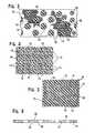
- FIG. 1is a cross-sectional view of a preferred embodiment of the material of the present invention illustrating a single layer vibration dissipating material with a support structure embedded therein, the material extends along a longitudinal portion of an implement and covers a proximal end thereof;
- FIG. 2is a cross-sectional view of the material of FIG. 1 separate from any implement, padding, equipment or the like;
- FIG. 2Ais a cross-sectional view of a second preferred embodiment of the material of the present invention with the support structure embedded thereon and the vibration dissipating material penetrating the support structure;
- FIG. 2Bis cross-sectional view of a third preferred embodiment of the material of the present invention with the support structure embedded within the vibration dissipating material and the vibration dissipating material penetrating the support structure, the support structure is positioned off center within the vibration dissipating material;
- FIG. 3is a cross-sectional view of a first preferred embodiment of the support structure as taken along the lines 3 - 3 of FIG. 2 , the support structure is formed of polymer and/or elastomer and/or fibers, either of which may contain fibers, passageways extend through the support structure allowing the vibration dissipating material to penetrate the support structure;
- FIG. 4is cross-sectional view of a second preferred embodiment of the support structure as viewed in a manner similar to that of FIG. 3 illustrating a support structure formed by woven fibers, passageways through the woven fibers allow the support structure to be penetrated by the vibration dissipating material;
- FIG. 5is cross-sectional view of a third preferred support structure as viewed in a manner similar to that of FIG. 3 ;
- the support structureis formed by pluralities of fibers and particles; passageways past the fibers allow the vibration dissipating material to preferably penetrate the support structure;
- FIG. 6is a side elevational view of the support structure of FIG. 3 ;
- FIG. 7is perspective view of the material of FIG. 1 configured to form a grip for a bat
- FIG. 8is perspective view of the material of FIG. 1 configured to form a grip for a racquet
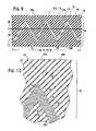
- FIG. 9is a cross-sectional view of a second preferred embodiment of the material of the present invention illustrating a single layer of vibration dissipating material with a support structure embedded therein; the support structure is disposed within the vibration dissipating material generally along a longitudinal axis in an at least partially non linear fashion so that a length of the support structure, as measured along a surface thereof, is greater than the length of the vibration dissipating material as measured along the longitudinal axis, of the material body;
- FIG. 10is an enlarged broken away view of the area enclosed by the dashed lines labeled “FIG. 10 ” in FIG. 9 and illustrates that the “overall support structure” can actually be formed by a plurality of individual stacked support structures (which can be the same or different from each other) or a successive plurality of stacked fibers and/or a successive plurality of stacked cloth layers;
- FIG. 11is a cross-sectional view of the material of FIG. 9 stretched along the longitudinal axis into a second position, in which the material body is elongated by a predetermined amount relative to the first position; the straightening of the support structure causes energy to be dissipated and preferably generally prevents further elongation of the material along the longitudinal axis past the second position;
- FIG. 12is a cross-sectional view of a third preferred embodiment of the material of the present invention illustrating a more linear support structure within the material while the material is in the first position; the more linear arrangement of the support structure in the material, relative to that shown in FIG. 9 , reduces the amount of elongation that is possible before the material stops stretching and effectively forms a brake on further movement;
- FIG. 13is a cross-sectional view of the material of FIG. 12 stretched along the longitudinal axis into the second position, in which the material is elongated along the longitudinal axis by a predetermined amount; because the support structure was more linear while the material was in the first position, relative to the material shown in FIG. 11 , it is preferred that the amount of elongation of the material when the material is in the second position is reduced relative to the material shown in FIGS. 9 and 11 ;
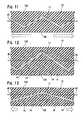
- FIG. 14is a cross-sectional view of a fourth preferred embodiment of the material of the present invention illustrating the support structure with an adhesive layer generally over its major surfaces to allow the elastomer material to be secured thereto rather than molded and/or extruded thereover;
- FIG. 15is a cross-sectional view of a fifth preferred embodiment of the material of the present invention illustrating the support structure, or ribbon material, positioned between two spaced elastomer layers with the support structure's peaks molded, fastened, and/or otherwise affixed to the elastomer layer at a plurality of locations; air gaps are preferably present about the support structure to facilitate longitudinal stretching of the material; alternatively, the support structure can be secured only at its lateral ends (i.e., the left and right ends of the support structure viewed in FIG. 15 ) to the elastomer layers so that the remainder of the support structure moves freely within an outer sheath of elastomer material and functions as a spring/elastic member to limit the elongation of the material;
- FIG. 16is a sixth preferred embodiment of the vibration dissipating material of the present invention and is similar to the material shown in FIG. 15 , except that the support structure's peaks are secured to the elastomer layers via an adhesive layer;
- FIG. 17is a seventh preferred embodiment of the vibration dissipating material of the present invention and illustrates the vibration dissipating material and any accompanying adhesive actually physically breaking when the support structure is elongated into the second position; the breaking of the vibration dissipating material results in further energy dissipation and vibration absorption in addition to that dissipated by the support structure;
- FIG. 18is an eighth preferred embodiment of the vibration dissipating material of the present invention and illustrates that the support structure, or ribbon material, can be disposed in any geometry within the vibration dissipating material; additionally, individually rigid squares, buttons, or plates (not shown) can be positioned on one side of the material to further spread impact force along the surface of the material prior to the dissipation of vibration by the material in general; additionally, such buttons, plates, or other rigid surfaces can be attached directly to a mesh or other flexible layer that is disposed over the material shown in FIG.
- the section line labeled 3 - 3 in this Figuresignifies that it is possible that the support structure shown in FIG. 18 is generally the same as that illustrated in FIG. 3 ;
- FIG. 19is a cross-sectional view of a ninth preferred embodiment of the material of the present invention and illustrates that the support structure can be positioned generally along an outer surface of the vibration dissipating material without departing from the scope of the present invention;
- FIG. 19also illustrates that a breakable layer (i.e., a paper layer) or a self fusing adhesive layer can be located on one surface of the material; when a self fusing layer is located on one surface of the material, the material can be wrapped so as to allow multiple adjacent wrappings of the material to fuse together to form an integral piece; if desired, the integral piece may be waterproof for use with swimming or the like;
- FIG. 20is a cross-sectional view of a tenth preferred embodiment of the vibration dissipating material with a shrinkable layer of material disposed on a major surface thereof;
- the shrinkable materialcan be a heat shrinkable material or any other type of shrinking material suitable for use with the present invention; once the material is properly positioned, the shrinkable layer can be used to fix the material in position and, preferably, can also be used as a separate breakable layer to further dissipate vibration in a fashion similar to the breakable layer described in connection with FIG. 17 ;
- FIG. 21is an eleventh preferred embodiment of the vibration dissipating material of the present invention and illustrates the shrinkable layer disposed within the vibration dissipating material;
- the shrinkable layercan be a solid layer, a perforated layer, a mesh or netting, or shrinkable fibers;
- FIG. 22is a twelfth preferred embodiment of the vibration absorbing material of the present invention and illustrates the shrinkable layer being disposed over peaks of the support structure with an optional vibration absorbing layer thereover;
- FIG. 23is a cross-sectional view of the material of FIG. 22 when the shrinkable layer has been shrunk down over the support structure after the material is placed in a desired configuration; although the optional additional vibration absorbing material is not shown in FIG. 23 , it can be left in position above the shrinkable layer to form a protective sheath or also pulled down into the gaps between the peaks of the support structure;
- FIG. 24illustrates the material of the present invention configured as athletic tape with an optional adhesive layer
- FIG. 25illustrates the material of the present invention as a roll of material/padding/wide wrap material or the like with an optional adhesive layer thereon;
- FIG. 26illustrates the material of the present invention configured as a knee bandage
- FIG. 27illustrates the material of the present invention with an optional adhesive layer configured as a finger and/or joint bandage; while various bandages, wraps, padding, materials, tapes, or the like are shown, the material of the present invention can be used for any purpose or application without departing from the scope of the present invention;
- FIG. 28illustrates the material of the present invention used to form a foot brace
- FIG. 29illustrates the material of the present invention wrapped to form a knee supporting brace
- FIG. 30illustrates additional layers of material used to brace the ligaments in a person's leg
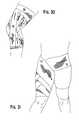
- FIG. 31illustrates the material of the present invention used to form a hip support
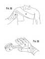
- FIG. 32illustrates the material of the present invention used to form a shoulder brace
- FIG. 33illustrates the material of the present invention wrapped to form a hand and wrist brace; while the material of the present invention has been shown in conjunction with various portions of the person's body, those of ordinary skill in the art will appreciate from this disclosure that the material of the present invention can be used as an athletic brace, a medical support, or a padding for any portion of a person's body without the departing from the scope of the present invention;
- FIG. 34is an elevational view of a baseball bat having a cover in the form of a sleeve on the handle area in accordance with this invention.
- FIG. 35is an enlarged fragmental cross-sectional view of the bat and sleeve shown in FIG. 34 ;
- FIG. 36is a schematic diagram showing the results in the application of shock forces on a cover in accordance with this invention.
- FIG. 37is a view similar to FIG. 35 showing an alternative sleeve mounted on a different implement
- FIG. 38is a view similar to FIGS. 35 and 39 showing still yet another form of sleeve in accordance with this invention
- FIG. 39is a cross-sectional longitudinal view showing an alternative cover in accordance with this invention mounted on a further type of implement;
- FIG. 39is a cross-sectional longitudinal view showing an alternative cover in accordance with this invention mounted on a further type of implement;
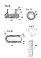
- FIG. 40is a cross-sectional end view of yet another cover in accordance with this invention.
- FIG. 41is an elevational view of a hammer incorporating an abrasive dampening handle in accordance with this invention
- FIG. 42is an elevational view showing a portion of a handlebar incorporating a vibration dampening cover in accordance with this invention
- FIG. 42is an elevational view showing a portion of a handlebar incorporating a vibration dampening cover in accordance with this invention.
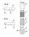
- FIG. 43is a view similar to FIG. 42 of yet another practice of this invention.
- FIGS. 44-47are plan views of various forms of the intermediate force dissipating layer which is used in certain practices of this invention.
- the material 10preferably includes a vibration dissipating material 12 (preferably an elastomer layer).
- a vibration dissipating material 12penetrates a support structure 17 to embed the support structure 17 thereon (as shown in FIG. 2A ) and/or therein (as shown in FIG. 2B ).
- the support structure 17is preferably semi-rigid (but can be rigid without departing from the scope of the present invention) and supports the vibration dissipating material 12 .
- the support structurecan be formed by a second elastomer layer of same or differing rigidity.
- the material 10 of the present inventionwas the result of extensive research and was thoroughly tested by Villanova University's Department of Mechanical Engineering by a professor having a Ph.D. in vibratory physics. Testing of the material 10 determined that the material 10 can reduce the magnitude of sensible vibration by eighty (80%) percent. The material 10 has verified, superior vibration dissipation properties due to the embedded support structure 17 that is located on and/or in the elastomer 12 . In addition to evenly distributing vibration, the support structure 17 contributes to the absorption of vibration and supports the vibration dissipating material 12 to prevent the layer of vibration dissipating material 12 from twisting or otherwise becoming unsuitable for use as a grip or padding.
- the vibration dissipating material layer 12be formed by elastomer
- the vibration dissipating material 12can be formed by any suitable polymer without departing from the scope of the present invention.
- the vibration dissipating material 12will be often described herein as being an elastomer without any mention of the material possibly being a polymer.
- the present inventionalso includes the material 12 being a any suitable polymer.
- the material 10 of the present inventioncan be incorporated into athletic gear, grips for sports equipment, grips for tools, and protective athletic gear. More specifically, the material 10 can be used: to form grips for a tennis racquet, hockey sticks, golf clubs, baseball bats or the like; to form protective athletic gear for mitts, headbands, mouth guards, face protection devices, helmets, gloves, to form athletic tape, to form braces, to form molded wraps for a portion of a person's body, to form pads, exercise pads, elevator pads, padding that is stood on, padding that is wrapped around objects to protect people from injury when colliding with such objects, padding that is worn for fashion, padding that is worn to ameliorate tennis elbow, padding that is used to support gun butts, padding that is used to support bullet proof vests, hip pads, shoulder pads, chest protectors, or the like; to form seats or handle bar covers for bicycles, motorcycles, or the like; to form boots for skiing, roller blading or the like; to form footwear, such as shoe soles and inserts
- the elastomer layer 12acts as a shock absorber by converting mechanical vibrational energy into heat energy.
- the embedded support structure 17redirects vibrational energy and provides increased stiffness to the material 10 to facilitate a user's ability to control an implement 20 encased, or partially encased, by the material 10 .
- the elastomer layer 12 , 12 A, or 12 Bmay include a plurality of fibers 14 (further described below) or a plurality of particles 15 (further described below).
- the incorporation of the support structure 17 on and/or within the material 10allows the material 10 to be formed by a single elastomer layer without the material 10 being unsuitable for at least some of the above-mentioned uses.
- the two elastomer layerscan be secured together via an adhesive layer, discreet adhesive locations, or using any other suitable method to secure the layers together.
- the support structureis preferably located and configured to support the first elastomer layer (see FIGS. 1-2B ).
- Suitable elastomer materialsinclude, but are not limited, urethane rubbers, silicone rubbers, nitrile rubbers, butyl rubbers, acrylic rubbers, natural rubbers, styrene-butadiene rubbers, and the like. In general, any suitable elastomer or polymer material can be used to form the vibration dissipating layer 12 .
- the elastomer 12is preferably used to absorb vibrational energy and to convert vibrational energy into heat energy.
- the elastomer 12also provides a compliant and comfortable grip for a user to grasp (or provides a surface for a portion of a user's body, such as the under sole of a user's foot when the material 10 is formed as a shoe insert).
- the material 10preferably has a Shore A durometer of approximately fifteen (15). In another embodiment, the material 10 preferably has a Shore A Shore Durometer of approximately forty two (42). In yet another embodiment, the material 10 preferably has a Shore A Durometer of approximately thirty-two (32). Of course, those of ordinary skill in the art will appreciate that the Shore A Durometer of the material 10 can varied without departing from the scope of the present invention.
- the support structure 17can include any one (or combination of) of a polymer, an elastomer, particles, a plurality of fibers, a plurality of woven fibers, a cloth, and a plurality of cloth layers. If the support structure 17 and the layer 12 are both polymers or both elastomers, then they can be the same or different from each other without departing from the scope of the present invention. If vibration dissipating material 12 is formed of the same material as the support structure 17 , then the support structure 17 can be made more rigid than the main layer 12 by embedding fibers 14 therein. It is preferable that the support structure 17 is generally more rigid than the vibration dissipating material 12 .
- the term “embed,” as used in the claim and in the corresponding portions of the specification,means “contact sufficiently to secure thereon and/or therein.” Accordingly, the support structure 17 shown in FIG. 2 A is embedded by the elastomer 12 even though the elastomer 12 does not fully enclose the support structure 17 . Additionally, as shown in FIG. 2 B, the support structure 17 can be located at any level or height within the elastomer 12 without departing from the scope of the present invention. While the passageways 19 are shown as extending completely through the support structure 17 , the invention includes passageways 19 that extend partially through the support structure 17 .
- the cloth layer 16can be formed of woven aramid fibers or other types of fiber.
- the aramid fibers 14block and redirect vibrational energy that passes through the elastomer 12 to facilitate the dissipation of vibrations.
- the aramid fibers 18redirect vibrational energy along the length of the fibers 18 .
- vibrational energy emanating from the implement 20 that is not absorbed or dissipated by the elastomer layer 12is redistributed evenly along the material 10 by the cloth 16 and preferably also further dissipated by the cloth 16 .
- the aramid fibers 18are formed of a suitable polyamide fiber of high tensile strength with a high resistance to elongation.
- any aramid fiber suitable to channel vibrationcan be used to form the support structure 17 without departing from scope of the present invention.
- loose aramid fibers or chopped aramid fiberscan be used to form the support structure 17 without departing from the scope of the present invention.
- the fibersmay also be formed of fiberglass or the like.
- the cloth 16include at least some floating aramid fibers 18 . That is, it is preferable that at least some of the plurality of aramid fibers 18 are able to move relative to the remaining aramid fibers 18 of the cloth 16 . This movement of some of the aramid fibers 18 relative to the remaining fibers of the cloth converts vibrational energy to heat energy.
- Particles 15can be located in either an elastomer layer 12 , 12 A, and/or 12 B and/or in the support structure 15 .
- the particles 15increase the vibration absorption of the material of the present invention.
- the particles 15can be formed of pieces of glass, polymer, elastomer, chopped aramid, ceramic, chopped fibers, sand, gel, foam, metal, mineral, glass beads, or the like. Gel particles 15 provide excellent vibration dampening due their low durometer rating.
- One exemplary gel that is suitable for use the present inventionis silicone gel. However, any suitable gel can be used without departing from the present invention.
- the material 10may be configured and adapted to form an insert for shoe.
- the material 10is preferably adapted to extend along an inner surface of the shoe from a location proximate to a heel of the shoe to the toe of the shoe.
- the material 10can be located along the sides and top of the shoe to protect the wearer's foot from lateral and vertical impacts.
- grip 22will be described below in connection with a baseball or softball bat, those of ordinary skill in the art will appreciate that the grip 22 can be used with any of the equipment, tools, or devices mentioned above without departing from the scope of the present invention.
- the grip 22When the grip 22 is used with a baseball or softball bat, the grip 22 preferably covers approximately seventeen (17) inches of the handle of the bat as well as covers the knob (i.e., the proximal end 26 of the implement 20 ) of the bat.
- the configuration of the grip 22 to extend over a significant portion of the bat lengthcontributes to increased vibrational damping. It is preferred, but not necessary, that the grip 22 be formed as a single, contiguous, one-piece member.
- one methodis to extrude the material 10 by pulling a support structure 17 from a supply roll while placing the elastomer layer on both sides of the support structure 17 . It is preferred, but not necessary, that the particles 15 in either of the support structure 17 or the elastomer layer are already located in their respective material on the appropriate supply roll.
- a second method of producing the material 10 of the present inventionis to weave a fiber onto the implement 20 and then to mold the elastomer 12 thereover.
- a support structurecan be pressure fit to an elastomer to form the material 10 .
- any other known manufacturing methodscan be used to form the material 10 without departing from the scope of the present invention. Any of the below described methods can be used to form a material 10 or grip 22 having any of the above specified Shore A Durometers and incorporating any of the above-described support structures 17 .
- one preferred method of making the material 10includes:
- the elastomer 12is cured so that some of the plurality of aramid fibers in the cloth layer 16 are able to move relative to the remaining plurality of aramid fibers 18 . It is also preferable that the material 10 be configured to form a grip for a bat and/or racquet having a handle 24 and the proximal end 26 .
- the grip 22preferably encloses at least a portion of the handle 24 and the proximal end 26 .
- Another aspect of the present inventionis directed to a method of making a grip 22 for an implement 20 having a handle 24 and a proximal end 26 .
- the grip 22is formed by a single layer material 10 adapted to regulate vibration.
- the methodincludes providing an uncured elastomer.
- a plurality of fibers 14are positioned on and/or within the uncured elastomer 12 .
- the uncured elastomer 12is at least partially cured to form the single layer material embedding the plurality of fibers.
- the single layer material 10has first and second major material surfaces.
- the single layer material 10is positioned over at least a portion of the handle 24 and over the proximal end 26 of the handle 24 .
- This methodcan be used to form a grip 22 having any of the Shore A Durometers described above and can use any of the support structure 17 also described above.
- the present inventionis directed to a method of making a material 10 adapted to regulate vibration.
- the methodincludes providing a cloth 16 formed by a plurality of woven aramid fibers 14 .
- the clothhas first and second major surfaces.
- a first elastomer layer 12 Ais placed on the first major surface of the cloth.
- a second elastomer layer 12 Bis placed on the second major surface 25 of the cloth 16 .
- the first and second elastomer layers 12 A, 12 Bpenetrate the cloth 16 to form a single layer elastomer 12 having an embedded cloth 16 for support thereof.
- the present inventionis directed to a method of forming a material 10 including providing a cloth layer 16 . Positioning an elastomer 12 substantially over the cloth layer 16 . Applying pressure to the cloth layer 16 and the elastomer 12 to embed the cloth layer 16 on and/or in the elastomer 12 to form the material 10 .
- this sort of pressure fit techniquethose ordinary skill in the art will appreciate from this disclosure that the cloth layer 16 and the elastomer 12 can be placed in a mold prior to applying pressure without departing from the scope of the present invention.
- FIGS. 1-6can be used as: an athletic tape, padding, bracing material, or the like (as shown in FIGS. 24-33 ) without departing from the scope of the present invention.
- an athletic tapefor wrapping a portion of a person's body; a material having a stretch axis and being adapted to regulate energy by disputing and partially dissipating energy exerted thereon; a padding for covering a portion of a person's body or an object; and/or a brace for wrapping a portion of a person's body is shown.
- the material 10will be initially described in connection with athletic tape, but those of ordinary skill in the art will appreciate from this disclosure that the material 10 can be used in any of the above described applications or in any other application where vibration absorption or having a controlled material stretch is desired.
- FIGS. 9 and 11illustrate a second preferred embodiment of the material of the present invention in the first and second positions, respectively.
- FIGS. 12 and 13illustrate a third preferred embodiment of the material of the present invention in the first and second positions, respectively.
- the configuration of the support structure 17 within the vibration absorbing layer 12allows the predetermined amount of elongation to be generally fixed so that the athletic tape provides a controlled support that allows limited movement before applying a brake on further movement of the wrapped portion of a person's body. This facilitates movement of a wrapped joint while simultaneously dissipating and absorbing vibration to allow superior comfort and performance as compared to that experienced with conventional athletic tape.
- the predetermined amount of elongationcan be set to any value, it is preferably less than twenty (20%) percent.
- the predetermined amount of elongationis more preferably less than two (2%) percent. However, depending on the application any amount of elongation can be used with the material 10 of the present invention.
- the tape body 64preferably includes a first elastomer layer 12 that defines a tape length 66 , as measured along the longitudinal axis 48 , of the tape body 64 .
- the support structure 17is preferably disposed within the elastomer layer 12 generally along the longitudinal axis 48 in an at least partially non linear fashion while the tape body is in the first position so that a length of the support structure 17 , as measured along a surface thereof, is greater than the tape length 66 of the first elastomer layer 12 . It is preferred, by not necessary, that the support structure 17 (or ribbon material) is positioned in a generally sinusoidal fashion within the elastomer layer 12 while the tape body 64 is in the first position.
- the support structure 17can be positioned in an irregular fashion without departing from the scope of the present invention.
- the support structure 17 and/or the elastomer layer 12can include particles, fibers, or the like (as shown in FIGS. 12 and 13 ).
- the support structure 17when the tape body 64 is stretched into the second position, the support structure 17 is preferably at least partially straightened so that the support structure 17 is more linear (or in case of the material shown in FIG. 2 , the support structure 17 would likely be thinner), relative to when the tape body 64 is in the first position (as shown in FIGS. 2 , 9 , and 12 ).
- the straightening of the support structurecauses energy to be dissipated and preferably generally prevents further elongation of the elastomer layer 12 along the longitudinal axis 48 past the second position. Energy dissipation occurs due to the stretching of the material of the support structure 17 and can occur due to the separation or partial pulling away of the support structure 17 from the attached elastomer layer 12 .
- the “overall support structure” 17may comprise a plurality of stacked support structures, fibers 18 , and/or cloth layers 16 . It is preferred that the plurality of fibers include aramid fibers or other high tensile strength fibrous material. Alternatively, the plurality of fibers may be formed of fiberglass material or be woven into a ribbon or cloth. Additionally, as described above in connection with FIGS. 2-6 , the support structure can include any one (or combination) of a polymer, an elastomer, particles; fibers; woven fibers; a cloth; a plurality of cloth layers; loose fibers, chopped fibers, gel particles, particles, sand, or the like without departing from the scope of the present invention.
- the support structure 17 and/or the elastomer layer 12may include a plurality of particles therein.
- Such particlesmay include any one or combination of gel particles, sand particles, glass beads, chopped fibers, metal particles, foam particles, sand, or any other particle in parting desirable vibration dissipation characteristics to the material 10 .
- the tape body 64have top and bottom surfaces 68 A, 68 B, respectively.
- the bottom surface 68 Bfaces the portion of the person's body when the athletic tape 10 is wrapped thereover.
- the support structure 17is formed by a plurality of fibers 18
- the plurality of fibers 18define multiple stacked fiber layers between the top and bottom surfaces 68 A, 68 B. It is preferable that the plurality of fibers 18 are stacked between four (4) and sixteen (16) times between the top and bottom surfaces 68 A, 68 B. It is more preferable still that the plurality of fibers are stacked ten (10) times.
- the plurality of fibers 18may include metal fibers, high tensile strength fibrous material, ceramic fibers, polymer fibers, elastomer fibers, or the like without departing from the scope of the present invention.
- the support structure 17may be disposed only partially within or on the elastomer layer generally along the longitudinal axis without departing from the scope of the present invention.
- the material of the present inventioncan be an all purpose material for use as desired by a person to regulate energy by distributing and partially dissipating energy exerted thereon.
- the all purpose material 10includes a material body 70 that is elongateable along the stretch axis 50 from a first position (shown in FIGS. 2 , 9 , and 12 ) to a second position (shown in FIGS. 11 and 13 ), in which the material body 70 is elongated by a predetermined amount relative to the first position.
- the stretch axis 50is preferably determined during manufacturing by the orientation and geometry of the support structure 17 which preferably limits the directions in which the material body 70 can elongate. If multiple separate material bodies 70 are stacked together, it may be desirable to have the stretch axis 50 of the individual material bodies 70 oriented askew from each other.
- the first elastomer layer 12defines a material length 72 , as measured along the stretch axis 50 of the material body 70 .
- the support structure 17is preferably disposed within the elastomer layer 12 generally along the stretch axis 50 in an at least partially non linear fashion while the material body 70 is in the first position so that a length of the support structure, as measured along the surface thereof, is greater than the material length 72 of the first elastomer layer.
- the support structure 17is at least partially straightened so that the support structure is more linear, relative to when the material body 70 is in the first position.
- the support structure 17is preferably positioned in a sinusoidal fashion within any of the materials 10 of the present invention.
- the support structure 17 or ribbonmay also be positioned in the form of a triangular wave, square wave, or an irregular fashion without departing from the scope of the present invention.
- any of the materials of the present inventionmay be formed with an elastomer layer 12 formed by silicone or any other suitable material.
- the vibration absorbing material 12may be a thermoset and/or may be free of voids therein.
- the paddingincludes a padding body 74 that is elongateable along the stretch axis from a first position (shown in FIGS. 2 , 9 , and 12 ) to a second position (shown in FIGS. 11 and 13 ), in which the padding body 74 is elongated by a predetermined amount relative to the first position.
- the paddingincludes a first elastomer layer 12 which defines a padding length 76 ,as measured along the stretch axis 50 of the padding body 74 .
- the support structure 17is disposed within the elastomer layer 12 generally along the stretch axis 50 in an at least partially non linear fashion while the padding body 74 is in the first position so that a length of the support structure 17 , is measured along a surface thereof, is greater than the padding length 76 of the first elastomer layer 12 .
- the support structure 17is at least partially straightened so that the support structure is more linear, relative to when the padding body 74 is in the first position.
- the straightening of the support structure 17causes energy to be dissipated and generally prevents further elongation of the elastomer layer along the stretch axis 50 past the second position.
- the braceprovides a controlled support for a wrapped portion of a person's body.
- the braceincludes a brace body 78 that is elongateable along the stretch axis 50 from a first position (shown in FIGS. 2 , 9 , and 12 ) to a second position (shown in FIGS. 11 and 13 ), in which the brace body 78 is elongated by a predetermined amount relative to the first position.
- the brace bodyincludes a first elastomer layer 12 that defines a brace length 80 , as measured along the stretch axis 50 , of the brace body 78 .
- the support structure 17is preferably disposed within the elastomer layer generally along the stretch axis 50 in an at least partially non linear fashion while the brace body 78 is in the first position so that a length of the support structure 17 , as measured along a surface thereof, is greater than the brace length 80 of the first elastomer layer 12 .
- the support structure 17is at least partially straightened so that the support structure 17 is more linear, relative to when the brace body 78 is in the first position.
- the straightening of the support structure 17causes energy to be dissipated and preferably generally prevents further elongation of the elastomer layer 12 along the stretch axis past the second position.
- any of the materials 10 of the present inventionmay be formed into a one piece brace that provides a controlled support as described above without departing from the scope of the present invention.
- the amount of stretch of the material 10can be selected. It is preferred that the percentage increase in the material length when the body 64 , 70 , 74 , 78 moves from the first position to the second position is selected based on a desired range of motion.
- the athletic tapemay be wrapped about a portion of a person's body multiple times, if necessary, to form a brace.
- a single layer of material 10can be wrapped on a person and secured in place using conventional athletic tape or the like. It is preferable that the successive wrappings of athletic tape are affixed to each other to form a generally one piece brace.
- One method of fusing wrappings of the athletic tapeis for the elastomer layer of each of the multiple adjacent wrappings to contact the elastomer layer of the adjacent wrappings to fuse together to form a single elastomer layer.
- Self fusing technologycan be used with any of the materials 10 of the present invention and can be used in any of the applications for which those materials are suitable.
- self fusing material 10can be used with baseball bats, lacrosse sticks, tennis rackets, gun covers and wraps, implements, sports implements, tape, padding, braces, or the like.
- adhesive 52may be used to connect the support structure 17 to the vibration absorbing material 12 .
- air gaps 60can be present proximate to the support structure 17 without departing from the scope of the present invention.
- the sixth preferred embodiment of the material of the present inventioncan be secured at its peak 62 to the vibrating absorbing material 12 or can be secured only at its ends with the vibration absorbing material 12 forming a protective sheath for the support structure 17 which would act as an elastic member in this instance.
- FIGS. 20-23illustrate the material 10 of the present invention incorporating a shrink layer 58 which can be used to secure the material 10 in position. Additionally, the shrinkable layer 58 may be configured to break when a certain stress threshold is reached to provide further energy dissipation. Referring to FIG. 22 , a shrinkable layer 58 is in its pre-shrink configuration. Referring to FIG. 23 , once the shrinkable layer 58 has been activated, the shrinkable layer 58 preferably deforms about one side of the support structure 17 to hold the material 10 in position.
- the shrinkable layer 58can be heat or water activated. Alternative known activation methods are also suitable for use with the present invention.
- FIG. 17illustrates a seventh preferred embodiment of the present invention in which the vibration absorbing layer 12 is configured to break apart during the elongation of the support structure 17 to allow for greater energy dissipation.
- any of the materials 10 of the present inventioncan be used in conjunction with additional layers of rigid or flexible materials without departing from the scope of the present invention.
- the materials 10 of the present inventionmay be used with a hard shell outer layer which is designed to dissipate impact energy over the entire material 10 prior to the material 10 deforming to dissipate energy.
- One type of rigid material that can be used in combination with the materials 10 of the present inventionis molded foam. Molded foam layers preferably include multiple flex seams that allow portions of the foam layer to at least partially move relative to each other even though the overall foam layer is a single body of material. This is ideal for turning an impact force into a more general blunt force that is spread over a larger area of the material 10 .
- individual foam pieces, buttons, rigid squares, or the likecan be directly attached to an outer surface of any of the materials 10 of the present invention.
- foam pieces, buttons, rigid squares, or the likecan be attached to a flexible layer or fabric that will dissipate received impact energy over the length of the fabric fibers prior to the dissipation of energy by the material 10 .
- FIGS. 34-35illustrate another embodiment of the present invention.
- a cover in the form of a sleeve 210is mounted on the handle or lower portion 218 of a baseball bat 210 .
- Sleeve 210is premolded so that it can be fit onto the handle portion of the bat 212 in a quick and convenient manner. This can be accomplished by having the sleeve 210 made of a stretchable or resilient material so that its upper end 214 would be pulled open and could be stretched to fit over the knob 217 of the bat 212 .
- sleeve 210may be provided with a longitudinal slit 16 to permit the sleeve to be pulled at least partially open and thereby facilitate snapping the sleeve 210 over the handle 218 of the bat 212 .
- the sleevewould remain mounted in place due to the tacky nature of the sleeve material and/or by the application of a suitable adhesive on the inner surface of the sleeve and/or on the outer surface of handle 218 .
- a characterizing feature of sleeve 210is that the lower end of the sleeve includes an outwardly extending peripheral knob 220 .
- Knob 220could be a separate cap snapped onto or secured in any other manner to the main portion of sleeve 210 .
- knob 220could be integral with and molded as part of the sleeve 210 .
- sleeve 210can be a single layer.
- the materialwould have the appropriate hardness and vibration dampening characteristics.
- the outer surface of the materialwould be tacky having high friction characteristics.
- the sleeve 210could be formed from a two layer laminate where the vibration absorbing material forms the inner layer disposed against the handle, with a separate tacky outer layer made from any suitable high friction material such as a thermoplastic material with polyurethane being one example.
- the two layer laminatewould have an inner elastomer layer which is characterized by its vibration dampening ability, while the main characteristic of the outer elastomer layer is its tackiness to provide a suitable gripping surface that would resist the tendency for the user's hand to slide off the handle.
- the provision of the knob 220also functions both as a stop member to minimize the tendency for the handle to slip from the user's hand and to cooperate in the vibration dampening affect.
- FIG. 36schematically shows what is believed to be the affect of the shock forces from vibration when the implement makes contact such as from the bat 212 striking a ball.
- FIG. 36shows the force vectors in accordance with a three layer laminate, such as illustrated in FIG. 35 , wherein elastomeric layers 222 , 224 are made of a silicone material.
- the intermediate layer 226is an aramid layer made of aramid fibers.
- the initial shock or vibrationis shown by the lateral or transverse arrows 228 on each side of the sleeve laminate 210 . This causes the elastomeric layers 222 , 224 to be compressed along the arc 230 .
- the inclusion of the intermediate layer 226 made from a force dissipating materialspreads the vibration longitudinally as shown by the arrows 232 .
- the linear spread of the vibrationcauses a rebound effect which totally dampens the vibration.
- the second series of testswere conducted using EASTON Bats (model #BK8) with the “645” KEVLAR in different combinations with silicone layers:
- the first bat testedwas comprised of one bottom layer of silicone with a middle layer of the “645” KEVLAR and one top layer of silicone referred to as “111”.
- the second bat testwas comprised of two bottom layers of silicone with a middle layer of KEVLAR and one top layer of silicone referred to as “211”.
- the third bat testedwas comprised of one bottom layer of silicone with a middle layer of KEVLAR and two top layers of silicone referred to as “112”.
- the “645” bat with the “111” configurationshowed the best reduction in vibration magnitudes.
- the sting-free gripsreduced the vibration in the baseball bats by both quantitative measures.
- the “645” KEVLAR in a “111” configurationwas the best in vibration reduction.
- the “645”reduced the bat's vibration in about 1 ⁇ 5 the time it took the control rubber grip to do so.
- the reduction in peak magnitude of vibrationranged from 60% to 80%, depending on the impact location and magnitude.
- a particularly preferred practice of the inventioninvolves a multilayer laminate having an aramid such as KEVLAR, sandwiched between layers of pure silicone.
- the above indicated testsshow dramatic results with this embodiment of the invention.
- the laminatecould comprise other combinations of layers such as a plurality of bottom layers of silicone or a plurality of top layers of silicone other variations include a repetitive laminate assembly wherein a vibration dampening layer is innermost with a force dissipating layer against the lower vibration dampening layer and then with a second vibration dampening layer over the force dissipating layer followed by a second force dissipating layer, etc. with the final laminate layer being a gripping layer which could also be made of vibration dampening material.
- the thickness limitationsand the desired vibration dampening properties.
- the various layerscould have different relative thicknesses.
- the vibration dampening layersuch as layer 222
- the outermost gripping layercould be of the same thickness as the vibration dampening layer, such as layer 224 shown in FIG. 35 or could be a thinner layer since the main function of the outer layer is to provide sufficient friction to assure a firm gripping action.
- a particularly advantageous feature of the invention where a force dissipating stiffening layer is usedis that the force dissipating layer could be very thin and still achieve its intended results.
- the force dissipating layerwould preferably be the thinnest of the layers, although it might be of generally the same thickness as the outer gripping layer.
- the laminatecould also include a plurality of vibration dampening layers (such as thin layers of gel material) and/or a plurality of stiffening force dissipating layers. Where such plural layers are used, the various layers could differ in the thickness from each other.
- FIGS. 34-35show the use of the invention where the sleeve 210 is mounted over a baseball bat 212 having a knob 217 .
- the same general type structurecould also be used where the implement does not have a knob similar to a baseball bat knob.
- FIG. 37illustrates a variation of the invention wherein the sleeve 210 A would be mounted on the handle 218 A of an implement that does not terminate in any knob.
- Such implementcould be various types of athletic equipment, tools, etc.
- the sleeve 210 Awould still have a knob 2220 A which would include an outer gripping layer 224 A, an intermediate force dissipating layer 226 A and an inner vibration dampening layer 222 A.
- the handle 218 Aextends into the knob 220 A.
- the inner layer 222 Awould have an accommodating recess 34 for receiving the handle 218 A.
- the inner layer 222 Awould also be of greater thickness in the knob area as illustrated.
- the cover 236includes one of the laminate variations where a force dissipating layer 242 is provided over the inner vibration dampening layer 240 with a second vibration dampening layer 244 applied over force dissipating layer 242 and with a final thin gripping layer 246 as the outermost layer.
- the two vibration dampening layers 240 and 244are the thickest layers and may be of the same or differing thickness from each other. The force dissipating layer 242 and outer gripping layer 244 are significantly thinner.
- FIG. 40shows a cover 236 A mounted over a hollow handle 238 A which is of non-circular cross-section.
- Handle 238 Amay, for example, have the octagonal shape of a tennis racquet.
- FIG. 41shows a further cover 236 B mounted over the handle portion of tool such as hammer 248 .
- the cover 236 Bis applied in tape form and would conform to the shape of the handle portion of hammer 248 .
- Other forms of coverscould also be applied rather than using a tape.
- the tapecould be used as a means for applying a cover to other types of implements.
- FIG. 42illustrates a cover 236 C mounted over the end of a handlebar, such as the handlebar of various types of cycles or any other device having a handlebar including steering wheels for vehicles and the like.
- FIG. 42also illustrates a variation where the cover 236 C has an outer contour with finger receiving recesses 252 . Such recesses could also be utilized for covers of other types of implements.
- FIG. 43illustrates a variation of the invention where the cover 236 D is mounted to the handle portion of an implement 254 with the extreme end 256 of the implement being bare.
- This illustrationis to show that the invention is intended to provide a vibration dampening gripping cover for the handle of an implement and that the cover need not extend beyond the gripping area.
- a force dissipating stiffening layeris provided as an intermediate layer of a multilayer laminate where there is at least one inner layer of vibration dampening material and an outer layer of gripping material with the possibility of additional layers of vibration dampening material and force dissipating layers of various thickness.
- the force dissipating layercould be innermost.
- the laminateincludes one or more layers in addition to the gripping layer and the stiffening layer and the vibration dampening layer.
- additional layer(s)could be incorporated at any location in the laminate, depending on its intended function (e.g., an adhesive layer, a cushioning layer, etc.).
- FIG. 44illustrates a force dissipating stiffening layer 258 in the form of a generally imperforate sheet.
- FIG. 45illustrates a force dissipating layer 260 in the form of an open mesh sheet. This is a particularly advantageous manner of forming the force dissipating layer where it is made of KEVLAR fibers.
- FIG. 46illustrates a variation where the force dissipating layer 262 is formed from a plurality of individual strips of material 264 which are parallel to each other and generally identical to each other in length and thickness as well as spacing.
- FIG. 44illustrates a force dissipating stiffening layer 258 in the form of a generally imperforate sheet.
- FIG. 45illustrates a force dissipating layer 260 in the form of an open mesh sheet. This is a particularly advantageous manner of forming the force dissipating layer where it is made of KEVLAR fibers.
- FIG. 46illustrates a variation where the force dissipating layer 26
- FIG. 47shows a variation where the force dissipating layer 266 is made of individual strips 268 of different sizes and which could be disposed in a more random fashion regarding their orientation. Although all of the strips 268 are illustrated in FIG. 47 as being parallel, non-parallel arrangements could also be used.
- the vibration dampening grip cover of this inventioncould be used for a wide number of implements.
- implementsinclude athletic equipment, hand tools and handlebars.
- athletic equipmentincludes bats, racquets, sticks, javelins, etc.
- toolsinclude hammers, screwdrivers, shovels, rakes, brooms, wrenches, pliers, knives, handguns, air hammers, etc.
- handlebarsinclude motorcycles, bicycles and various types of steering wheels.
- a preferred practice of this inventionis to incorporate a force dissipating layer, particularly an aramid, such as KEVLAR fiber, into a composite with at least two elastomers.
- a force dissipating layerparticularly an aramid, such as KEVLAR fiber
- One elastomer layerwould function as a vibration dampening material and the other outer elastomer layer which would function as a gripping layer.
- the outer elastomer layercould also be a vibration dampening material.
- the outer layercompletely covers the composite.
- the elastomer layersmay have different degrees of hardness, coefficient of friction and dampening of vibration.
- the thicknesses of the various layerscould also vary in accordance with the intended use. Examples of ranges of hardness for the inner vibration dampening layer and the outer gripping layer (which may also be a vibration absorbing layer) are 5-70 Durometer Shore A.
- One of the layersmay have a range of 5-20 Durometer Shore A and the other a range of 30-70 Durometer Shore A for either of these layers.
- the vibration dampening layercould have a hardness of less than 5, and could even be a 000 Durometer reading.
- the vibration dampening materialcould be a gel, such as a silicone gel or a gel of any other suitable material.
- the coefficient of friction as determined by conventional measuring techniques for the tacky and non-porus gripping layeris preferably at least 0.5 and may be in the range of 0.6-1.5. A more preferred range is 0.7-1.2 with a still more preferred range being about 0.8-1.
- the outer gripping layerwhen also used as a vibration dampening layer, could have the same thickness as the inner layer. When used solely as a gripping layer the thickness could be generally the same as the intermediate layer, which might be about 1/20 to 1 ⁇ 4 of the thickness of the vibration dampening layer.
- the handle portion of the implementcould be of cylindrical shape with a uniform diameter and smooth outer surface such as the golf club handle 238 shown in FIG. 37 .
- the handlecould taper such as the bat handle shown in FIGS. 34-35 .
- Other illustrated geometric shapesinclude the octagonal tennis racquet handle 238 A shown in FIG. 40 or a generally oval type handle such as the hammer 248 shown in FIG. 41 .
- the inventionis not limited to any particular geometric shape.
- the implementcould have an irregular shape such as a handle bar with finger receiving depressions as shown in FIG. 42 .
- the inner layer of the covercould press against and generally conform to the outer surface of the handle and the outermost gripping layer of the cover could include its own finger receiving depressions.
- the covermay be of uniform thickness of a shape conforming to the irregularities in the outer surface of the handle.
- the material 10may include additional layers (e.g., two or more additional layers) without departing from the scope of the present invention. It is understood, therefore, that this invention is not limited to the particular embodiments disclosed, but is intended to cover all modifications which are within the spirit and scope of the invention as defined by the appended claims and/or shown in the attached drawings.
Landscapes
- Health & Medical Sciences (AREA)
- General Health & Medical Sciences (AREA)
- Physical Education & Sports Medicine (AREA)
- Engineering & Computer Science (AREA)
- Mechanical Engineering (AREA)
- Biomedical Technology (AREA)
- Textile Engineering (AREA)
- Heart & Thoracic Surgery (AREA)
- Vascular Medicine (AREA)
- Life Sciences & Earth Sciences (AREA)
- Animal Behavior & Ethology (AREA)
- Public Health (AREA)
- Veterinary Medicine (AREA)
- Professional, Industrial, Or Sporting Protective Garments (AREA)
- Orthopedics, Nursing, And Contraception (AREA)
Abstract
Description
Claims (54)
Priority Applications (26)
| Application Number | Priority Date | Filing Date | Title |
|---|---|---|---|
| US10/958,745US8142382B2 (en) | 2001-08-27 | 2004-10-05 | Vibration dampening material and method of making same |
| US10/999,246US20050144808A1 (en) | 2001-08-27 | 2004-11-30 | Vibration dampening material and method of making same |
| US11/019,568US7171697B2 (en) | 2001-08-27 | 2004-12-22 | Vibration dampening material and method of making same |
| MX2007004202AMX2007004202A (en) | 2004-10-05 | 2005-10-05 | Vibration dampening material and uses for same. |
| CA2583309ACA2583309C (en) | 2004-10-05 | 2005-10-05 | Vibration dampening material and uses for same |
| KR1020097001976AKR100986414B1 (en) | 2004-10-05 | 2005-10-05 | Vibration dampening material and uses for same |
| KR1020117005051AKR101208779B1 (en) | 2004-10-05 | 2005-10-05 | Vibration dampening material and uses for same |
| EP05809057AEP1804934A4 (en) | 2004-10-05 | 2005-10-05 | Vibration dampening material and uses for same |
| KR1020077010091AKR20070059208A (en) | 2004-10-05 | 2005-10-05 | Vibration-Reducing Materials and Their Applications |
| CN2005800394479ACN101065168B (en) | 2004-10-05 | 2005-10-05 | Vibration dampening material and method of making same |
| KR1020107018991AKR101151064B1 (en) | 2004-10-05 | 2005-10-05 | Vibration dampening material and uses for same |
| KR1020107007641AKR20100058626A (en) | 2004-10-05 | 2005-10-05 | Vibration dampening material and uses for same |
| TW94134880ATWI409039B (en) | 2004-10-05 | 2005-10-05 | Vibration dampening material and uses for same |
| PCT/US2005/035774WO2006041892A2 (en) | 2004-10-05 | 2005-10-05 | Vibration dampening material and uses for same |
| TW102130368ATWI542287B (en) | 2004-10-05 | 2005-10-05 | Vibration dampening material and uses for same |
| US11/304,079US20060168710A1 (en) | 2001-08-27 | 2005-12-15 | Vibration dampening material and method of making same |
| US11/304,995US20060157901A1 (en) | 2001-08-27 | 2005-12-15 | Vibration dampening material and method of making same |
| US12/570,499US20100247856A1 (en) | 2001-08-27 | 2009-09-30 | Vibration dampening material and method of making same |
| US13/084,866US20110314589A1 (en) | 2001-08-27 | 2011-04-12 | Vibration dampening material |
| US13/155,522US20110302700A1 (en) | 2001-08-27 | 2011-06-08 | Vibration dampening material |
| US13/944,123US20130302601A1 (en) | 2001-08-27 | 2013-07-17 | Vibration dampening material |
| US13/944,131US20140017436A1 (en) | 2001-08-27 | 2013-07-17 | Vibration dampening material |
| US13/944,127US20130302561A1 (en) | 2001-08-27 | 2013-07-17 | Vibration dampening material |
| US14/887,732US20160037885A1 (en) | 2001-08-27 | 2015-10-20 | Vibration dampening material |
| US15/049,696US10888134B2 (en) | 2001-08-27 | 2016-02-22 | Helmet padding system |
| US15/085,274US20160377139A1 (en) | 2001-08-27 | 2016-03-30 | Vibration dampening material |
Applications Claiming Priority (4)
| Application Number | Priority Date | Filing Date | Title |
|---|---|---|---|
| US09/939,319US6652398B2 (en) | 2001-08-27 | 2001-08-27 | Vibration dampening grip cover for the handle of an implement |
| US10/659,560US6935973B2 (en) | 2001-08-27 | 2003-09-10 | Vibration dampening material |
| US10/856,215US6942586B2 (en) | 2001-08-27 | 2004-05-28 | Vibration dampening material |
| US10/958,745US8142382B2 (en) | 2001-08-27 | 2004-10-05 | Vibration dampening material and method of making same |
Related Parent Applications (2)
| Application Number | Title | Priority Date | Filing Date |
|---|---|---|---|
| US10/856,215Continuation-In-PartUS6942586B2 (en) | 2001-08-27 | 2004-05-28 | Vibration dampening material |
| US10/958,952Continuation-In-PartUS20050137038A1 (en) | 2001-08-27 | 2004-10-05 | Vibration dampening material and method of making same |
Related Child Applications (4)
| Application Number | Title | Priority Date | Filing Date |
|---|---|---|---|
| US10/958,611Continuation-In-PartUS7150113B2 (en) | 2001-08-27 | 2004-10-05 | Vibration dampening material and method of making same |
| US10/958,952Continuation-In-PartUS20050137038A1 (en) | 2001-08-27 | 2004-10-05 | Vibration dampening material and method of making same |
| US10/999,246Continuation-In-PartUS20050144808A1 (en) | 2001-08-27 | 2004-11-30 | Vibration dampening material and method of making same |
| US11/304,995Continuation-In-PartUS20060157901A1 (en) | 2001-08-27 | 2005-12-15 | Vibration dampening material and method of making same |
Publications (2)
| Publication Number | Publication Date |
|---|---|
| US20050137514A1 US20050137514A1 (en) | 2005-06-23 |
| US8142382B2true US8142382B2 (en) | 2012-03-27 |
Family
ID=40328779
Family Applications (1)
| Application Number | Title | Priority Date | Filing Date |
|---|---|---|---|
| US10/958,745Active2026-02-19US8142382B2 (en) | 2001-08-27 | 2004-10-05 | Vibration dampening material and method of making same |
Country Status (1)
| Country | Link |
|---|---|
| US (1) | US8142382B2 (en) |
Cited By (13)
| Publication number | Priority date | Publication date | Assignee | Title |
|---|---|---|---|---|
| US8613114B1 (en) | 2012-07-25 | 2013-12-24 | 2nd Skull, LLC | Head guard |
| US20150065314A1 (en)* | 2011-12-28 | 2015-03-05 | John Inzer | Gripper wraps |
| USD732832S1 (en)* | 2013-10-11 | 2015-06-30 | Mueller Sports Medicine, Inc. | Precut tape with surface ornamentation |
| USD734616S1 (en)* | 2013-10-11 | 2015-07-21 | Mueller Sports Medicine, Inc. | Precut tape with surface ornamentation |
| USD734615S1 (en)* | 2013-10-11 | 2015-07-21 | Mueller Sports Medicine, Inc. | Precut tape with surface ornamentation |
| WO2016141479A1 (en)* | 2015-03-09 | 2016-09-15 | 9206558 Canada Corporation | Blade protector and grip |
| USD787690S1 (en)* | 2014-08-19 | 2017-05-23 | Kt Health, Llc | Kinesiology tape with an x-shaped configuration |
| US20180090179A1 (en)* | 2016-09-27 | 2018-03-29 | Seagate Technology Llc | Mounting structure for hard disk drives |
| US10239282B1 (en) | 2017-02-21 | 2019-03-26 | Countervail Products, Llc | Vibration-damping laminate stack |
| US10384106B2 (en) | 2017-11-16 | 2019-08-20 | Easton Diamond Sports, Llc | Ball bat with shock attenuating handle |
| US10709946B2 (en) | 2018-05-10 | 2020-07-14 | Easton Diamond Sports, Llc | Ball bat with decoupled barrel |
| US10898606B2 (en) | 2018-05-15 | 2021-01-26 | Legacy Research and Development Group, LLC | Self-fusing low density silicone |
| US11013968B2 (en) | 2018-03-26 | 2021-05-25 | Easton Diamond Sports, Llc | Adjustable flex rod connection for ball bats and other sports implements |
Families Citing this family (6)
| Publication number | Priority date | Publication date | Assignee | Title |
|---|---|---|---|---|
| ATE326200T1 (en)* | 2003-09-25 | 2006-06-15 | Power Wrap Internat Trading Gm | INTRODUCTION OF COSMETICS INTO THE SKIN |
| US20080000740A1 (en)* | 2006-06-09 | 2008-01-03 | Hiroshi Ohara | Damper Structure with Silicon Layer and Manufacturing Method Thereof |
| US8753360B2 (en) | 2010-11-08 | 2014-06-17 | Covidien Lp | Expandable mesh system and method of use therefor |
| US10945874B2 (en) | 2012-05-15 | 2021-03-16 | Akervall Technologies, Inc. | Custom-formable night grinding appliance and method of use |
| US20180071132A1 (en)* | 2016-09-15 | 2018-03-15 | Hi-Max Innovation Co,.Ltd | Mat structure |
| US10751212B2 (en)* | 2017-06-26 | 2020-08-25 | Maryam Raza | Multilayer dressing device and method for preventing and treating pressure ulcers and chronic wounds |
Citations (139)
| Publication number | Priority date | Publication date | Assignee | Title |
|---|---|---|---|---|
| US1125029A (en) | 1914-01-23 | 1915-01-12 | Allan E Lard | Shaft for golf-clubs. |
| US1195994A (en) | 1916-08-29 | Shaft for golf clubs | ||
| US1498838A (en) | 1923-03-16 | 1924-06-24 | Jr James Thomas Harrison | Pneumatic shoe |
| US1551203A (en) | 1922-12-05 | 1925-08-25 | H L Leonard Rod Co | Golf club |
| US1620118A (en) | 1922-05-15 | 1927-03-08 | Crawford Mcgregor & Canby Co | Golf club |
| US1701856A (en) | 1925-04-08 | 1929-02-12 | Kroydon Company | Handle grip and method of making the same |
| US1772414A (en) | 1928-07-13 | 1930-08-05 | Brooke-Hunt Godfrey Leveson | Shock absorber, resilient suspension means, and the like |
| US2023131A (en) | 1932-09-05 | 1935-12-03 | Gibson Robert James | Steel shaft for golf clubs |
| GB458367A (en) | 1935-06-15 | 1936-12-15 | Dunlop Rubber Co | Improvements in and relating to handle grips |
| US2099521A (en) | 1936-07-17 | 1937-11-16 | Harold W Herkimer | Baseball bat |
| US2871899A (en) | 1958-04-16 | 1959-02-03 | Bridgeport Hardware Mfg Corp | Tool handles |
| US3256130A (en)* | 1961-08-03 | 1966-06-14 | Carolina Insulating Yarn Compa | Multi-break fabric |
| US3353981A (en) | 1963-01-28 | 1967-11-21 | Michael S Striker | Plastic articles of manufacture and methods of preparing the same |
| US3606326A (en) | 1968-09-25 | 1971-09-20 | William J Sparks | Grip for hand powered implements |
| US3716433A (en) | 1970-09-18 | 1973-02-13 | Plummer Walter A | Method of equipping a tool handle or hand grip with a tough adherent protective layer with enhanced gripping properties |
| US3730509A (en) | 1970-04-15 | 1973-05-01 | R Jorn | Composite spring element for use as a motor mount |
| US3779551A (en) | 1971-12-10 | 1973-12-18 | Aluminum Co Of America | Indicator element for ball bat |
| US3791050A (en) | 1972-01-19 | 1974-02-12 | Wolverine World Wide Inc | Shoe sole and heel |
| US3862882A (en) | 1972-09-25 | 1975-01-28 | Owens Corning Fiberglass Corp | Glass fiber reinforced elastomers |
| US4015851A (en) | 1976-02-09 | 1977-04-05 | Elastomeric Products Inc. | Rubber grip for tennis racket handles |
| US4044625A (en) | 1976-07-01 | 1977-08-30 | Chicago Pneumatic Tool Company | Vibration isolating hand grip for shank of a percussive chisel |
| US4134198A (en) | 1975-08-27 | 1979-01-16 | `Totes`, Incorporated | Method of installing grip on handle |
| US4143109A (en) | 1976-07-15 | 1979-03-06 | Arbrook, Inc. | Method of making medical glove |
| US4147443A (en) | 1975-07-03 | 1979-04-03 | S & S Medical Products Co., Inc. | Handle for a medical instrument |
| DE2805314A1 (en) | 1978-02-06 | 1979-08-09 | Benno Prof Dr Krieg | Shock absorbing grip for tennis racket handle - has outer layer of textile to absorb perspiration |
| US4197611A (en) | 1978-09-14 | 1980-04-15 | Lincoln Manufacturing Company, Inc. | Hand grip for cooking utensil handle |
| US4237177A (en) | 1978-11-03 | 1980-12-02 | General Signal Corporation | Corrosion-resistant coated articles |
| US4261567A (en) | 1979-06-11 | 1981-04-14 | `Totes`, Incorporated | Hand grip |
| US4268574A (en) | 1978-07-13 | 1981-05-19 | Pantec S.R.L. | Prefabricated self-supporting panels and manufacture process thereof |
| US4338270A (en) | 1979-06-11 | 1982-07-06 | `Totes`, Incorporated | Method of fabricating a composite foam hand held implement grip |
| US4347280A (en) | 1981-07-08 | 1982-08-31 | Geos Corporation | Shock absorbing sheet material |
| US4417042A (en) | 1982-02-17 | 1983-11-22 | General Electric Company | Scavengers for one-component alkoxy-functional RTV compositions and processes |
| US4483972A (en) | 1983-02-01 | 1984-11-20 | General Electric Company | Integrated cross-linkers and amine functional siloxane scavengers for RTV silicone rubber compositions |
| US4526828A (en) | 1983-06-27 | 1985-07-02 | Pioneer Industrial Products Company | Protective apparel material and method for producing same |
| US4552713A (en) | 1983-02-04 | 1985-11-12 | Jamak, Inc. | Method of forming an improved handgrip having non-slip features |
| US4575446A (en) | 1982-08-27 | 1986-03-11 | Helmut Schaefer | Process for producing an insole for shoes |
| US4591160A (en) | 1983-03-17 | 1986-05-27 | 'Pininfarina S.p.A. | Golf club head |
| US4597578A (en) | 1984-02-15 | 1986-07-01 | Eaton Corporation | Golf club grip |
| US4613537A (en) | 1984-04-19 | 1986-09-23 | Industrie-Entwicklungen Krupper | Grip tapes based on plastic-coated supporting materials |
| US4660832A (en) | 1985-03-25 | 1987-04-28 | Shomo Robert D | Shock and vibration absorbent handle |
| US4668563A (en)* | 1986-06-12 | 1987-05-26 | Johnson & Johnson Products, Inc. | Conformable fiberglass casting tape |
| US4706788A (en) | 1985-04-15 | 1987-11-17 | Melles Griot, Irvine Company | Vibration damped apparatus |
| US4736949A (en) | 1985-10-16 | 1988-04-12 | Nippon Gakki Seizo Kabushiki Kaisha | Racket frame having particularly positioned grip |
| US4819939A (en) | 1985-10-30 | 1989-04-11 | Maruman Golf Co., Ltd. | Grip for a golf club shaft |
| US4864738A (en) | 1988-07-19 | 1989-09-12 | Zvi Horovitz | Sole construction for footwear |
| US4912836A (en) | 1987-01-30 | 1990-04-03 | Avetoom Garnic C | Method of installing a sports equipment grip |
| US4919420A (en) | 1987-08-28 | 1990-04-24 | Daiwa Golf Co., Ltd. | Grip of a golf club and a manufacturing method thereof |
| US4948131A (en) | 1988-05-14 | 1990-08-14 | Kabushiki Kaisha Sigel | Vibration dampening racket |
| US4953862A (en) | 1989-04-18 | 1990-09-04 | Uke Alan K | Hand grip for sporting equipment or tools |
| US4983242A (en) | 1988-11-02 | 1991-01-08 | Roland Reed | Tennis racquet having a sandwich construction, vibration-dampening frame |
| US4989643A (en) | 1988-12-20 | 1991-02-05 | Chase-Walton Elastomers, Inc. | High performance composite hose |
| US5005254A (en) | 1989-09-12 | 1991-04-09 | `Totes`, Incorporated | Handle grip |
| US5083780A (en) | 1989-03-28 | 1992-01-28 | Spalding & Evenflo Companies, Inc. | Golf club shaft having selective reinforcement |
| US5088734A (en) | 1990-07-09 | 1992-02-18 | Glava Gary L | Attenuating handle for recreational and work implements |
| US5110653A (en) | 1990-12-11 | 1992-05-05 | Supracor Systems, Inc. | Shock absorbing wrap for sporting equipment |
| US5122405A (en) | 1990-12-11 | 1992-06-16 | Supracor Systems, Inc. | Shock absorbing means for sporting equipment handles |
| US5137769A (en) | 1990-12-11 | 1992-08-11 | Supracor Systems, Inc. | Vibration dampening means for strung or spoked equipment |
| US5193246A (en) | 1991-07-23 | 1993-03-16 | Huang Ing Chung | Air cushion grip with a cubic supporting structure and shock-absorbing function |
| US5199706A (en) | 1992-05-18 | 1993-04-06 | Dennis Chen | Grip assembly for a racket |
| US5203561A (en) | 1992-04-08 | 1993-04-20 | Lanctot Paul A | Vibration dampening handle having metal particles and a viscus fluid |
| US5240247A (en) | 1990-07-13 | 1993-08-31 | Head Sport Aktiengesellschaft | Racquet for ball games |
| US5254391A (en) | 1990-06-04 | 1993-10-19 | Elbert Davis | Soft, elastomeric, polymer coated contact surface |
| US5258088A (en) | 1991-12-02 | 1993-11-02 | Wu Yun Lin | Golf grip assembly process |
| US5261665A (en) | 1992-02-11 | 1993-11-16 | Robert A. Paley, Inc. | Golf club grip formed of a plurality of materials and method of manufacture thereof |
| US5267487A (en) | 1990-07-19 | 1993-12-07 | Cabot Safety Corporation | Vibration handle grip and process for making same |
| US5269516A (en) | 1991-12-30 | 1993-12-14 | Gencorp Inc. | Racquet handle |
| US5282618A (en) | 1992-06-25 | 1994-02-01 | Bonny Sports Corp. | Racket with improved shock-absorbing means |
| US5290036A (en) | 1993-04-12 | 1994-03-01 | Frank Fenton | Cavity back iron with vibration dampening material in rear cavity |
| US5294119A (en) | 1991-09-27 | 1994-03-15 | Taylor Made Golf Company, Inc. | Vibration-damping device for a golf club |
| US5319867A (en) | 1991-12-12 | 1994-06-14 | Spenco Medical Corporation | Electrically conductive shoe insole |
| US5322285A (en) | 1992-11-23 | 1994-06-21 | Turner Terry S | Golf putter |
| US5322280A (en) | 1993-06-28 | 1994-06-21 | Jan Sports Products Corp. | Racket handle |
| US5322290A (en) | 1990-12-30 | 1994-06-21 | Maruman Golf Kabushiki Kaisha | Golf club grip |
| US5333861A (en) | 1993-05-14 | 1994-08-02 | Mills Peter B | Golf club |
| US5338600A (en) | 1991-08-19 | 1994-08-16 | Medical Materials Corporation | Composite thermoplastic material including a compliant layer |
| US5339793A (en) | 1993-05-13 | 1994-08-23 | Findley Alan T | Bow stabilizer |
| US5348303A (en) | 1993-02-12 | 1994-09-20 | Bullet Golf Ball, Inc. | Golf club grip |
| US5355552A (en) | 1991-07-23 | 1994-10-18 | Huang Ing Chung | Air cushion grip with a cubic supporting structure and shock-absorbing function |
| US5362046A (en) | 1993-05-17 | 1994-11-08 | Steven C. Sims, Inc. | Vibration damping |
| US5377979A (en) | 1994-02-03 | 1995-01-03 | Progroup, Inc. | Backspin reducing putter |
| US5384083A (en) | 1992-08-14 | 1995-01-24 | The United States Of America As Represented By The Administrator Of The National Aeronautics & Space Administration | Method for forming a glove attachment |
| US5395108A (en) | 1994-01-19 | 1995-03-07 | Easton Aluminum, Inc. | Simulated wood composite ball bat |
| US5435549A (en) | 1993-12-14 | 1995-07-25 | Chen; Dennis | Grip for sporting equipment |
| US5463824A (en) | 1993-06-16 | 1995-11-07 | Barna; Randall S. | Arch support system and method for manufacture and use |
| US5511777A (en) | 1994-02-03 | 1996-04-30 | Grover Products Co. | Ball bat with rebound core |
| US5516101A (en) | 1993-02-16 | 1996-05-14 | Peng; Jung-Ching | Game racket handle |
| US5524885A (en) | 1995-03-22 | 1996-06-11 | Heo; Yeong K. | Terry cloth golf club grip |
| US5528842A (en) | 1989-02-08 | 1996-06-25 | The Rockport Company, Inc. | Insert for a shoe sole |
| US5540982A (en)* | 1993-01-25 | 1996-07-30 | Minnesota Mining And Manufacturing Company | Fabric backing for orthopedic support materials |
| US5547189A (en) | 1994-07-20 | 1996-08-20 | Billings; David P. | Golf club and club shaft constructions |
| US5575473A (en) | 1992-11-23 | 1996-11-19 | Turner; Terry S. | Golf club |
| US5593158A (en) | 1995-12-21 | 1997-01-14 | Jas D. Easton, Inc. | Shock attenuating ball bat |
| US5621914A (en) | 1995-02-27 | 1997-04-22 | Hardcore Sports, Inc. | Protective garment for sports participation |
| US5624114A (en) | 1993-08-06 | 1997-04-29 | Kelsey; Douglas A. | Ball bat shock damper |
| USD379208S (en) | 1995-08-22 | 1997-05-13 | Tacki-Mac Grips, Inc. | Sporting equipment handle grip |
| US5636377A (en) | 1992-08-19 | 1997-06-10 | Hipco, Inc. | Hip protection device for the elderly |
| US5653643A (en) | 1995-11-20 | 1997-08-05 | Pendulum Corp. | Vibration absorbing material for handles of sporting equipment |
| US5655975A (en) | 1995-06-07 | 1997-08-12 | Roush Anatrol, Inc. | Golf club having vibration damping device and method for making same |
| US5657985A (en) | 1992-11-03 | 1997-08-19 | Dahlstroem; Christer | Handle for sports equipment |
| US5673437A (en) | 1995-05-08 | 1997-10-07 | Chase Ergonomics Inc. | Vibration attenuating member and method of making same |
| US5686158A (en) | 1991-11-21 | 1997-11-11 | Jmk International, Inc. | Low specific gravity silicone rubber golf club grip |
| US5695408A (en) | 1996-01-24 | 1997-12-09 | Goldwin Golf Usa, Inc. | Golf club shaft |
| US5725487A (en)* | 1995-06-07 | 1998-03-10 | Johnson & Johnson Professional, Inc. | Orthopedic casting tape |
| US5730662A (en) | 1996-10-21 | 1998-03-24 | Rens; Peter J. | Grip assembly and method |
| US5749798A (en) | 1996-08-15 | 1998-05-12 | Wilson Sporting Goods Co. | Racket for tennis or the like games |
| US5759113A (en) | 1996-06-21 | 1998-06-02 | Minnesota Mining And Manufacturing Company | Vibration damped golf clubs and ball bats |
| US5772524A (en) | 1991-01-14 | 1998-06-30 | Huang; Ben | Water retarding golf club grip |
| US5789327A (en) | 1995-08-28 | 1998-08-04 | Rousseau; Wm. Richard | Armor panel |
| US5840397A (en) | 1996-11-08 | 1998-11-24 | Supracor Systems, Inc. | Sports pad |
| US5843851A (en) | 1992-12-02 | 1998-12-01 | Randemo Inc. | Composites |
| US5842933A (en) | 1996-12-19 | 1998-12-01 | Lewis; William H. | Implement grip with built-in shock absorber |
| US5858521A (en) | 1994-07-25 | 1999-01-12 | Lintec Corporation | Vibration damper material comprising a vicso elastic layer of unvulcanized rubber |
| US5912195A (en) | 1996-05-14 | 1999-06-15 | United Technologies Corporation | Elastomer coated layer for erosion and/or fire protection |
| US5916664A (en) | 1995-06-05 | 1999-06-29 | Robert C. Bogart | Multi-celled cushion and method of its manufacture |
| US5926847A (en) | 1997-07-01 | 1999-07-27 | Eibert; Bruce A. | Golf practice glove |
| US5944617A (en) | 1995-11-20 | 1999-08-31 | Pendulum Corporation | Vibration absorbing material for handles of sporting equipment |
| US5946734A (en) | 1997-04-15 | 1999-09-07 | Vogan; Richard B. | Head protector apparatus |
| US5963989A (en) | 1998-07-27 | 1999-10-12 | Robertson; Donald R. | Soccer headband |
| US5979081A (en) | 1995-08-01 | 1999-11-09 | Vaz; Guy Andrew | Blast and fragment resistant safety boot footwear |
| US6000062A (en) | 1997-10-14 | 1999-12-14 | Trakh; Maz | Protective headband for soccer players |
| US6007439A (en) | 1997-04-14 | 1999-12-28 | Hillerich & Bradsby Co. | Vibration dampener for metal ball bats and similar impact implements |
| US6030355A (en) | 1997-11-12 | 2000-02-29 | 3M Innovative Properties Company | Orthopedic support material containing a silicate |
| US6074965A (en)* | 1995-08-25 | 2000-06-13 | Beiersdorf Ag | Support material for medical purposes |
| US6077793A (en) | 1995-08-24 | 2000-06-20 | Oy Oms Optomedical Systems Ltd. | Method for producing elastic protective material and elastic protective material |
| US6167639B1 (en) | 1997-09-19 | 2001-01-02 | George Ventura | Puncture resistant insole |
| US6216276B1 (en) | 1997-07-01 | 2001-04-17 | Bruce A. Eibert | Padded athletic gloves |
| US6219940B1 (en) | 1998-05-22 | 2001-04-24 | Mizuno Corporation | Athletic shoe midsole design and construction |
| US6231946B1 (en) | 1999-01-15 | 2001-05-15 | Gordon L. Brown, Jr. | Structural reinforcement for use in a shoe sole |
| US20010008053A1 (en) | 2000-01-19 | 2001-07-19 | Benetton Group S.P.A. | Vibration absorbing device, particularly for shoes or sports implements |
| US20010055994A1 (en) | 1997-10-16 | 2001-12-27 | Kwitek Benjamin J. | Grip |
| US6368989B1 (en) | 1999-01-12 | 2002-04-09 | E. I. Du Pont De Nemours And Company | Puncture resistant composite |
| US6416432B1 (en) | 2000-05-02 | 2002-07-09 | Structured Composites, Lp | Composite sports racket |
| US6511927B1 (en)* | 1998-09-08 | 2003-01-28 | Brookwood Companies, Inc. | Breathable waterproof laminate and method for making same |
| US6544910B2 (en)* | 1997-07-12 | 2003-04-08 | Beiersdorf Ag | Backing material for medical purposes |
| US6578836B2 (en) | 2000-12-14 | 2003-06-17 | The Yokohama Rubber Co., Ltd. | Shock absorber for automobile |
| US20040048701A1 (en) | 2001-08-27 | 2004-03-11 | Innercore Grip Company | Vibration dampening grip cover for the handle of an implement |
| US6969548B1 (en) | 1999-08-30 | 2005-11-29 | Goldfine Andrew A | Impact absorbing composite |
| US7207962B2 (en)* | 2002-07-16 | 2007-04-24 | Alcare Co., Ltd. | Stretch fabric substrate for medical use |
| US7285505B2 (en)* | 2004-08-27 | 2007-10-23 | Milliken & Company | Tape having weft-insert warp knit fabric reinforcement |
Family Cites Families (5)
| Publication number | Priority date | Publication date | Assignee | Title |
|---|---|---|---|---|
| US55994A (en)* | 1866-07-03 | Improved gas-purifier | ||
| US6505421B1 (en)* | 1995-03-01 | 2003-01-14 | Bfr Holdings Limited | Blast and fragment resistent polyurethane boot sole for safety footwear |
| US6586110B1 (en)* | 2000-07-07 | 2003-07-01 | Delphi Technologies, Inc. | Contoured metal structural members and methods for making the same |
| US6880269B2 (en)* | 2001-10-16 | 2005-04-19 | Sting Free Company | Athletic clothing with sting reduction padding |
| JP4711606B2 (en)* | 2003-05-14 | 2011-06-29 | アトム株式会社 | Gloves having anti-vibration performance and manufacturing method thereof |
- 2004
- 2004-10-05USUS10/958,745patent/US8142382B2/enactiveActive
Patent Citations (142)
| Publication number | Priority date | Publication date | Assignee | Title |
|---|---|---|---|---|
| US1195994A (en) | 1916-08-29 | Shaft for golf clubs | ||
| US1125029A (en) | 1914-01-23 | 1915-01-12 | Allan E Lard | Shaft for golf-clubs. |
| US1620118A (en) | 1922-05-15 | 1927-03-08 | Crawford Mcgregor & Canby Co | Golf club |
| US1551203A (en) | 1922-12-05 | 1925-08-25 | H L Leonard Rod Co | Golf club |
| US1498838A (en) | 1923-03-16 | 1924-06-24 | Jr James Thomas Harrison | Pneumatic shoe |
| US1701856A (en) | 1925-04-08 | 1929-02-12 | Kroydon Company | Handle grip and method of making the same |
| US1772414A (en) | 1928-07-13 | 1930-08-05 | Brooke-Hunt Godfrey Leveson | Shock absorber, resilient suspension means, and the like |
| US2023131A (en) | 1932-09-05 | 1935-12-03 | Gibson Robert James | Steel shaft for golf clubs |
| GB458367A (en) | 1935-06-15 | 1936-12-15 | Dunlop Rubber Co | Improvements in and relating to handle grips |
| US2099521A (en) | 1936-07-17 | 1937-11-16 | Harold W Herkimer | Baseball bat |
| US2871899A (en) | 1958-04-16 | 1959-02-03 | Bridgeport Hardware Mfg Corp | Tool handles |
| US3256130A (en)* | 1961-08-03 | 1966-06-14 | Carolina Insulating Yarn Compa | Multi-break fabric |
| US3353981A (en) | 1963-01-28 | 1967-11-21 | Michael S Striker | Plastic articles of manufacture and methods of preparing the same |
| US3606326A (en) | 1968-09-25 | 1971-09-20 | William J Sparks | Grip for hand powered implements |
| US3730509A (en) | 1970-04-15 | 1973-05-01 | R Jorn | Composite spring element for use as a motor mount |
| US3716433A (en) | 1970-09-18 | 1973-02-13 | Plummer Walter A | Method of equipping a tool handle or hand grip with a tough adherent protective layer with enhanced gripping properties |
| US3779551A (en) | 1971-12-10 | 1973-12-18 | Aluminum Co Of America | Indicator element for ball bat |
| US3791050A (en) | 1972-01-19 | 1974-02-12 | Wolverine World Wide Inc | Shoe sole and heel |
| US3862882A (en) | 1972-09-25 | 1975-01-28 | Owens Corning Fiberglass Corp | Glass fiber reinforced elastomers |
| US4147443A (en) | 1975-07-03 | 1979-04-03 | S & S Medical Products Co., Inc. | Handle for a medical instrument |
| US4134198A (en) | 1975-08-27 | 1979-01-16 | `Totes`, Incorporated | Method of installing grip on handle |
| US4015851A (en) | 1976-02-09 | 1977-04-05 | Elastomeric Products Inc. | Rubber grip for tennis racket handles |
| US4044625A (en) | 1976-07-01 | 1977-08-30 | Chicago Pneumatic Tool Company | Vibration isolating hand grip for shank of a percussive chisel |
| US4143109A (en) | 1976-07-15 | 1979-03-06 | Arbrook, Inc. | Method of making medical glove |
| DE2805314A1 (en) | 1978-02-06 | 1979-08-09 | Benno Prof Dr Krieg | Shock absorbing grip for tennis racket handle - has outer layer of textile to absorb perspiration |
| US4268574A (en) | 1978-07-13 | 1981-05-19 | Pantec S.R.L. | Prefabricated self-supporting panels and manufacture process thereof |
| US4197611A (en) | 1978-09-14 | 1980-04-15 | Lincoln Manufacturing Company, Inc. | Hand grip for cooking utensil handle |
| US4237177A (en) | 1978-11-03 | 1980-12-02 | General Signal Corporation | Corrosion-resistant coated articles |
| US4261567A (en) | 1979-06-11 | 1981-04-14 | `Totes`, Incorporated | Hand grip |
| US4338270A (en) | 1979-06-11 | 1982-07-06 | `Totes`, Incorporated | Method of fabricating a composite foam hand held implement grip |
| US4347280A (en) | 1981-07-08 | 1982-08-31 | Geos Corporation | Shock absorbing sheet material |
| US4417042A (en) | 1982-02-17 | 1983-11-22 | General Electric Company | Scavengers for one-component alkoxy-functional RTV compositions and processes |
| US4575446A (en) | 1982-08-27 | 1986-03-11 | Helmut Schaefer | Process for producing an insole for shoes |
| US4483972A (en) | 1983-02-01 | 1984-11-20 | General Electric Company | Integrated cross-linkers and amine functional siloxane scavengers for RTV silicone rubber compositions |
| US4552713A (en) | 1983-02-04 | 1985-11-12 | Jamak, Inc. | Method of forming an improved handgrip having non-slip features |
| US4591160A (en) | 1983-03-17 | 1986-05-27 | 'Pininfarina S.p.A. | Golf club head |
| US4526828B1 (en) | 1983-06-27 | 1989-04-04 | ||
| US4526828A (en) | 1983-06-27 | 1985-07-02 | Pioneer Industrial Products Company | Protective apparel material and method for producing same |
| US4597578A (en) | 1984-02-15 | 1986-07-01 | Eaton Corporation | Golf club grip |
| US4613537A (en) | 1984-04-19 | 1986-09-23 | Industrie-Entwicklungen Krupper | Grip tapes based on plastic-coated supporting materials |
| US4660832A (en) | 1985-03-25 | 1987-04-28 | Shomo Robert D | Shock and vibration absorbent handle |
| US4706788A (en) | 1985-04-15 | 1987-11-17 | Melles Griot, Irvine Company | Vibration damped apparatus |
| US4736949A (en) | 1985-10-16 | 1988-04-12 | Nippon Gakki Seizo Kabushiki Kaisha | Racket frame having particularly positioned grip |
| US4819939A (en) | 1985-10-30 | 1989-04-11 | Maruman Golf Co., Ltd. | Grip for a golf club shaft |
| US4668563A (en)* | 1986-06-12 | 1987-05-26 | Johnson & Johnson Products, Inc. | Conformable fiberglass casting tape |
| US4912836A (en) | 1987-01-30 | 1990-04-03 | Avetoom Garnic C | Method of installing a sports equipment grip |
| US4919420A (en) | 1987-08-28 | 1990-04-24 | Daiwa Golf Co., Ltd. | Grip of a golf club and a manufacturing method thereof |
| US4948131A (en) | 1988-05-14 | 1990-08-14 | Kabushiki Kaisha Sigel | Vibration dampening racket |
| US4864738A (en) | 1988-07-19 | 1989-09-12 | Zvi Horovitz | Sole construction for footwear |
| US4983242A (en) | 1988-11-02 | 1991-01-08 | Roland Reed | Tennis racquet having a sandwich construction, vibration-dampening frame |
| US4989643A (en) | 1988-12-20 | 1991-02-05 | Chase-Walton Elastomers, Inc. | High performance composite hose |
| US5528842A (en) | 1989-02-08 | 1996-06-25 | The Rockport Company, Inc. | Insert for a shoe sole |
| US5083780A (en) | 1989-03-28 | 1992-01-28 | Spalding & Evenflo Companies, Inc. | Golf club shaft having selective reinforcement |
| US5042804A (en) | 1989-04-18 | 1991-08-27 | Alan K. Uke | Hand grip for sporting equipment or tools |
| US4953862A (en) | 1989-04-18 | 1990-09-04 | Uke Alan K | Hand grip for sporting equipment or tools |
| US5005254A (en) | 1989-09-12 | 1991-04-09 | `Totes`, Incorporated | Handle grip |
| US5254391A (en) | 1990-06-04 | 1993-10-19 | Elbert Davis | Soft, elastomeric, polymer coated contact surface |
| US5088734A (en) | 1990-07-09 | 1992-02-18 | Glava Gary L | Attenuating handle for recreational and work implements |
| US5240247A (en) | 1990-07-13 | 1993-08-31 | Head Sport Aktiengesellschaft | Racquet for ball games |
| US5267487A (en) | 1990-07-19 | 1993-12-07 | Cabot Safety Corporation | Vibration handle grip and process for making same |
| US5137769A (en) | 1990-12-11 | 1992-08-11 | Supracor Systems, Inc. | Vibration dampening means for strung or spoked equipment |
| US5122405A (en) | 1990-12-11 | 1992-06-16 | Supracor Systems, Inc. | Shock absorbing means for sporting equipment handles |
| US5110653A (en) | 1990-12-11 | 1992-05-05 | Supracor Systems, Inc. | Shock absorbing wrap for sporting equipment |
| US5322290A (en) | 1990-12-30 | 1994-06-21 | Maruman Golf Kabushiki Kaisha | Golf club grip |
| US5772524A (en) | 1991-01-14 | 1998-06-30 | Huang; Ben | Water retarding golf club grip |
| US5193246A (en) | 1991-07-23 | 1993-03-16 | Huang Ing Chung | Air cushion grip with a cubic supporting structure and shock-absorbing function |
| US5355552A (en) | 1991-07-23 | 1994-10-18 | Huang Ing Chung | Air cushion grip with a cubic supporting structure and shock-absorbing function |
| US5338600A (en) | 1991-08-19 | 1994-08-16 | Medical Materials Corporation | Composite thermoplastic material including a compliant layer |
| US5294119A (en) | 1991-09-27 | 1994-03-15 | Taylor Made Golf Company, Inc. | Vibration-damping device for a golf club |
| US5686158A (en) | 1991-11-21 | 1997-11-11 | Jmk International, Inc. | Low specific gravity silicone rubber golf club grip |
| US5258088A (en) | 1991-12-02 | 1993-11-02 | Wu Yun Lin | Golf grip assembly process |
| US5319867A (en) | 1991-12-12 | 1994-06-14 | Spenco Medical Corporation | Electrically conductive shoe insole |
| US5269516A (en) | 1991-12-30 | 1993-12-14 | Gencorp Inc. | Racquet handle |
| US5261665A (en) | 1992-02-11 | 1993-11-16 | Robert A. Paley, Inc. | Golf club grip formed of a plurality of materials and method of manufacture thereof |
| US5203561A (en) | 1992-04-08 | 1993-04-20 | Lanctot Paul A | Vibration dampening handle having metal particles and a viscus fluid |
| US5199706A (en) | 1992-05-18 | 1993-04-06 | Dennis Chen | Grip assembly for a racket |
| US5282618A (en) | 1992-06-25 | 1994-02-01 | Bonny Sports Corp. | Racket with improved shock-absorbing means |
| US5384083A (en) | 1992-08-14 | 1995-01-24 | The United States Of America As Represented By The Administrator Of The National Aeronautics & Space Administration | Method for forming a glove attachment |
| US5636377A (en) | 1992-08-19 | 1997-06-10 | Hipco, Inc. | Hip protection device for the elderly |
| US5657985A (en) | 1992-11-03 | 1997-08-19 | Dahlstroem; Christer | Handle for sports equipment |
| US5322285A (en) | 1992-11-23 | 1994-06-21 | Turner Terry S | Golf putter |
| US5575473A (en) | 1992-11-23 | 1996-11-19 | Turner; Terry S. | Golf club |
| US5843851A (en) | 1992-12-02 | 1998-12-01 | Randemo Inc. | Composites |
| US5540982A (en)* | 1993-01-25 | 1996-07-30 | Minnesota Mining And Manufacturing Company | Fabric backing for orthopedic support materials |
| US5348303A (en) | 1993-02-12 | 1994-09-20 | Bullet Golf Ball, Inc. | Golf club grip |
| US5516101A (en) | 1993-02-16 | 1996-05-14 | Peng; Jung-Ching | Game racket handle |
| US5290036A (en) | 1993-04-12 | 1994-03-01 | Frank Fenton | Cavity back iron with vibration dampening material in rear cavity |
| US5339793A (en) | 1993-05-13 | 1994-08-23 | Findley Alan T | Bow stabilizer |
| US5333861A (en) | 1993-05-14 | 1994-08-02 | Mills Peter B | Golf club |
| US5362046A (en) | 1993-05-17 | 1994-11-08 | Steven C. Sims, Inc. | Vibration damping |
| US5463824A (en) | 1993-06-16 | 1995-11-07 | Barna; Randall S. | Arch support system and method for manufacture and use |
| US5322280A (en) | 1993-06-28 | 1994-06-21 | Jan Sports Products Corp. | Racket handle |
| US5624114A (en) | 1993-08-06 | 1997-04-29 | Kelsey; Douglas A. | Ball bat shock damper |
| US5435549A (en) | 1993-12-14 | 1995-07-25 | Chen; Dennis | Grip for sporting equipment |
| US5395108A (en) | 1994-01-19 | 1995-03-07 | Easton Aluminum, Inc. | Simulated wood composite ball bat |
| US5511777A (en) | 1994-02-03 | 1996-04-30 | Grover Products Co. | Ball bat with rebound core |
| US5377979A (en) | 1994-02-03 | 1995-01-03 | Progroup, Inc. | Backspin reducing putter |
| US5547189A (en) | 1994-07-20 | 1996-08-20 | Billings; David P. | Golf club and club shaft constructions |
| US5858521A (en) | 1994-07-25 | 1999-01-12 | Lintec Corporation | Vibration damper material comprising a vicso elastic layer of unvulcanized rubber |
| US5621914A (en) | 1995-02-27 | 1997-04-22 | Hardcore Sports, Inc. | Protective garment for sports participation |
| US5524885A (en) | 1995-03-22 | 1996-06-11 | Heo; Yeong K. | Terry cloth golf club grip |
| US5673437A (en) | 1995-05-08 | 1997-10-07 | Chase Ergonomics Inc. | Vibration attenuating member and method of making same |
| US5916664A (en) | 1995-06-05 | 1999-06-29 | Robert C. Bogart | Multi-celled cushion and method of its manufacture |
| US5655975A (en) | 1995-06-07 | 1997-08-12 | Roush Anatrol, Inc. | Golf club having vibration damping device and method for making same |
| US5725487A (en)* | 1995-06-07 | 1998-03-10 | Johnson & Johnson Professional, Inc. | Orthopedic casting tape |
| US5979081A (en) | 1995-08-01 | 1999-11-09 | Vaz; Guy Andrew | Blast and fragment resistant safety boot footwear |
| USD379208S (en) | 1995-08-22 | 1997-05-13 | Tacki-Mac Grips, Inc. | Sporting equipment handle grip |
| US6077793A (en) | 1995-08-24 | 2000-06-20 | Oy Oms Optomedical Systems Ltd. | Method for producing elastic protective material and elastic protective material |
| US6074965A (en)* | 1995-08-25 | 2000-06-13 | Beiersdorf Ag | Support material for medical purposes |
| US5789327A (en) | 1995-08-28 | 1998-08-04 | Rousseau; Wm. Richard | Armor panel |
| US5944617A (en) | 1995-11-20 | 1999-08-31 | Pendulum Corporation | Vibration absorbing material for handles of sporting equipment |
| US5653643A (en) | 1995-11-20 | 1997-08-05 | Pendulum Corp. | Vibration absorbing material for handles of sporting equipment |
| US5593158A (en) | 1995-12-21 | 1997-01-14 | Jas D. Easton, Inc. | Shock attenuating ball bat |
| US5695408A (en) | 1996-01-24 | 1997-12-09 | Goldwin Golf Usa, Inc. | Golf club shaft |
| US5912195A (en) | 1996-05-14 | 1999-06-15 | United Technologies Corporation | Elastomer coated layer for erosion and/or fire protection |
| US5759113A (en) | 1996-06-21 | 1998-06-02 | Minnesota Mining And Manufacturing Company | Vibration damped golf clubs and ball bats |
| US5749798A (en) | 1996-08-15 | 1998-05-12 | Wilson Sporting Goods Co. | Racket for tennis or the like games |
| US5730662A (en) | 1996-10-21 | 1998-03-24 | Rens; Peter J. | Grip assembly and method |
| US5840397A (en) | 1996-11-08 | 1998-11-24 | Supracor Systems, Inc. | Sports pad |
| US5842933A (en) | 1996-12-19 | 1998-12-01 | Lewis; William H. | Implement grip with built-in shock absorber |
| US6007439A (en) | 1997-04-14 | 1999-12-28 | Hillerich & Bradsby Co. | Vibration dampener for metal ball bats and similar impact implements |
| US5946734A (en) | 1997-04-15 | 1999-09-07 | Vogan; Richard B. | Head protector apparatus |
| US5926847A (en) | 1997-07-01 | 1999-07-27 | Eibert; Bruce A. | Golf practice glove |
| US6216276B1 (en) | 1997-07-01 | 2001-04-17 | Bruce A. Eibert | Padded athletic gloves |
| US6544910B2 (en)* | 1997-07-12 | 2003-04-08 | Beiersdorf Ag | Backing material for medical purposes |
| US6167639B1 (en) | 1997-09-19 | 2001-01-02 | George Ventura | Puncture resistant insole |
| US6000062A (en) | 1997-10-14 | 1999-12-14 | Trakh; Maz | Protective headband for soccer players |
| US20010055994A1 (en) | 1997-10-16 | 2001-12-27 | Kwitek Benjamin J. | Grip |
| US6558270B2 (en) | 1997-10-16 | 2003-05-06 | Benjamin J. Kwitek | Grip |
| US6030355A (en) | 1997-11-12 | 2000-02-29 | 3M Innovative Properties Company | Orthopedic support material containing a silicate |
| US6219940B1 (en) | 1998-05-22 | 2001-04-24 | Mizuno Corporation | Athletic shoe midsole design and construction |
| US5963989A (en) | 1998-07-27 | 1999-10-12 | Robertson; Donald R. | Soccer headband |
| US6511927B1 (en)* | 1998-09-08 | 2003-01-28 | Brookwood Companies, Inc. | Breathable waterproof laminate and method for making same |
| US6368989B1 (en) | 1999-01-12 | 2002-04-09 | E. I. Du Pont De Nemours And Company | Puncture resistant composite |
| US6231946B1 (en) | 1999-01-15 | 2001-05-15 | Gordon L. Brown, Jr. | Structural reinforcement for use in a shoe sole |
| US6969548B1 (en) | 1999-08-30 | 2005-11-29 | Goldfine Andrew A | Impact absorbing composite |
| US20010008053A1 (en) | 2000-01-19 | 2001-07-19 | Benetton Group S.P.A. | Vibration absorbing device, particularly for shoes or sports implements |
| US6416432B1 (en) | 2000-05-02 | 2002-07-09 | Structured Composites, Lp | Composite sports racket |
| US6578836B2 (en) | 2000-12-14 | 2003-06-17 | The Yokohama Rubber Co., Ltd. | Shock absorber for automobile |
| US20040048701A1 (en) | 2001-08-27 | 2004-03-11 | Innercore Grip Company | Vibration dampening grip cover for the handle of an implement |
| US7207962B2 (en)* | 2002-07-16 | 2007-04-24 | Alcare Co., Ltd. | Stretch fabric substrate for medical use |
| US7285505B2 (en)* | 2004-08-27 | 2007-10-23 | Milliken & Company | Tape having weft-insert warp knit fabric reinforcement |
Non-Patent Citations (1)
| Title |
|---|
| Database WIP Week 198711, Derwent Publications Ltd., London, GB; AN 1987-075332, Feb. 5, 1987 (Abstract). |
Cited By (22)
| Publication number | Priority date | Publication date | Assignee | Title |
|---|---|---|---|---|
| US9731160B2 (en)* | 2011-12-28 | 2017-08-15 | John Inzer | Gripper wraps |
| US20150065314A1 (en)* | 2011-12-28 | 2015-03-05 | John Inzer | Gripper wraps |
| US20150174442A1 (en)* | 2011-12-28 | 2015-06-25 | John Inzer | Gripper wraps |
| USD848558S1 (en) | 2011-12-28 | 2019-05-14 | Inzer Advance Designs, Inc. | Weightlifting wrap |
| US9895594B2 (en) | 2011-12-28 | 2018-02-20 | Inzer Advance Designs, Inc. | Weightlifting wrap |
| US9415256B2 (en)* | 2011-12-28 | 2016-08-16 | Inzer Advance Designs, Inc. | Gripper wraps |
| US8763166B1 (en) | 2012-07-25 | 2014-07-01 | 2nd Skull, LLC | Head guard |
| US8997265B2 (en) | 2012-07-25 | 2015-04-07 | 2nd Skull, LLC | Head guard |
| US8613114B1 (en) | 2012-07-25 | 2013-12-24 | 2nd Skull, LLC | Head guard |
| USD732832S1 (en)* | 2013-10-11 | 2015-06-30 | Mueller Sports Medicine, Inc. | Precut tape with surface ornamentation |
| USD734615S1 (en)* | 2013-10-11 | 2015-07-21 | Mueller Sports Medicine, Inc. | Precut tape with surface ornamentation |
| USD734616S1 (en)* | 2013-10-11 | 2015-07-21 | Mueller Sports Medicine, Inc. | Precut tape with surface ornamentation |
| USD787690S1 (en)* | 2014-08-19 | 2017-05-23 | Kt Health, Llc | Kinesiology tape with an x-shaped configuration |
| WO2016141479A1 (en)* | 2015-03-09 | 2016-09-15 | 9206558 Canada Corporation | Blade protector and grip |
| US20180090179A1 (en)* | 2016-09-27 | 2018-03-29 | Seagate Technology Llc | Mounting structure for hard disk drives |
| US10239282B1 (en) | 2017-02-21 | 2019-03-26 | Countervail Products, Llc | Vibration-damping laminate stack |
| US10384106B2 (en) | 2017-11-16 | 2019-08-20 | Easton Diamond Sports, Llc | Ball bat with shock attenuating handle |
| US11013968B2 (en) | 2018-03-26 | 2021-05-25 | Easton Diamond Sports, Llc | Adjustable flex rod connection for ball bats and other sports implements |
| US11731017B2 (en) | 2018-03-26 | 2023-08-22 | Easton Diamond Sports, Llc | Adjustable flex rod connection for ball bats and other sports implements |
| US10709946B2 (en) | 2018-05-10 | 2020-07-14 | Easton Diamond Sports, Llc | Ball bat with decoupled barrel |
| US11951368B2 (en) | 2018-05-10 | 2024-04-09 | Easton Diamond Sports, Llc | Ball bat with decoupled barrel |
| US10898606B2 (en) | 2018-05-15 | 2021-01-26 | Legacy Research and Development Group, LLC | Self-fusing low density silicone |
Also Published As
| Publication number | Publication date |
|---|---|
| US20050137514A1 (en) | 2005-06-23 |
Similar Documents
| Publication | Publication Date | Title |
|---|---|---|
| US9265999B2 (en) | Vibration dampening material and method of making same | |
| US8297601B2 (en) | Vibration dampening material and method of making same | |
| CA2583309C (en) | Vibration dampening material and uses for same | |
| US8545966B2 (en) | Vibration dampening material and uses for same | |
| US20040213979A1 (en) | Material adapted to dissipate and reduce vibrations and method of making same | |
| US8142382B2 (en) | Vibration dampening material and method of making same | |
| US20070149079A1 (en) | Vibration dampening material and method of making same | |
| US20160037885A1 (en) | Vibration dampening material | |
| US20110302700A1 (en) | Vibration dampening material | |
| US20100247856A1 (en) | Vibration dampening material and method of making same | |
| US20060168710A1 (en) | Vibration dampening material and method of making same | |
| US7150113B2 (en) | Vibration dampening material and method of making same | |
| CA2838341A1 (en) | Vibration dampening material | |
| US20050144808A1 (en) | Vibration dampening material and method of making same | |
| US20030228819A1 (en) | Material adapted to dissipate and reduce vibrations and method of making same | |
| US20030228817A1 (en) | Material adapted to dissipate and reduce vibrations and method of making same | |
| US20050137038A1 (en) | Vibration dampening material and method of making same | |
| US20050137025A1 (en) | Vibration dampening material and method of making same | |
| US20050142967A1 (en) | Vibration dampening material and method of making same | |
| HK1195461A (en) | Vibration dampening material |
Legal Events
| Date | Code | Title | Description |
|---|---|---|---|
| AS | Assignment | Owner name:STING FREE COMPANY, PENNSYLVANIA Free format text:ASSIGNMENT OF ASSIGNORS INTEREST;ASSIGNORS:VITO, ROBERT A.;DIMARIO, CARMEN N.;FALONE, THOMAS;REEL/FRAME:015854/0125 Effective date:20050304 | |
| AS | Assignment | Owner name:STING FREE TECHNOLOGIES COMPANY, PENNSYLVANIA Free format text:CHANGE OF NAME;ASSIGNOR:STING FREE COMPANY;REEL/FRAME:016745/0948 Effective date:20050101 | |
| AS | Assignment | Owner name:VITO, LISA, PENNSYLVANIA Free format text:ASSIGNMENT OF ASSIGNORS INTEREST;ASSIGNOR:STINGFREE TECHNOLOGIES COMPANY;REEL/FRAME:021217/0353 Effective date:20080229 Owner name:VITO, ROBERT, PENNSYLVANIA Free format text:ASSIGNMENT OF ASSIGNORS INTEREST;ASSIGNOR:STINGFREE TECHNOLOGIES COMPANY;REEL/FRAME:021217/0353 Effective date:20080229 | |
| AS | Assignment | Owner name:STINGFREE TECHNOLOGIES COMPANY, PENNSYLVANIA Free format text:CHANGE OF NAME;ASSIGNOR:STING FREE TECHNOLOGIES COMPANY;REEL/FRAME:021428/0924 Effective date:20070731 | |
| AS | Assignment | Owner name:MATSCITECHNO LICENSING COMPANY, PENNSYLVANIA Free format text:ASSIGNMENT OF ASSIGNORS INTEREST;ASSIGNORS:VITO, ROBERT A.;VITO, LISA E.;REEL/FRAME:026663/0570 Effective date:20110621 | |
| STCF | Information on status: patent grant | Free format text:PATENTED CASE | |
| AS | Assignment | Owner name:ALLIANCE BANK, PENNSYLVANIA Free format text:SECURITY AGREEMENT;ASSIGNOR:MATSCITECHNO LICENSING COMPANY;REEL/FRAME:030573/0351 Effective date:20130531 | |
| AS | Assignment | Owner name:MAINLINE SPECIAL OP UT, LLC, PENNSYLVANIA Free format text:SECURITY INTEREST;ASSIGNOR:MATSCITECHNO LICENSING COMPANY;REEL/FRAME:034119/0419 Effective date:20131107 | |
| FPAY | Fee payment | Year of fee payment:4 | |
| MAFP | Maintenance fee payment | Free format text:PAYMENT OF MAINTENANCE FEE, 8TH YR, SMALL ENTITY (ORIGINAL EVENT CODE: M2552); ENTITY STATUS OF PATENT OWNER: SMALL ENTITY Year of fee payment:8 | |
| FEPP | Fee payment procedure | Free format text:MAINTENANCE FEE REMINDER MAILED (ORIGINAL EVENT CODE: REM.); ENTITY STATUS OF PATENT OWNER: SMALL ENTITY | |
| FEPP | Fee payment procedure | Free format text:11.5 YR SURCHARGE- LATE PMT W/IN 6 MO, SMALL ENTITY (ORIGINAL EVENT CODE: M2556); ENTITY STATUS OF PATENT OWNER: SMALL ENTITY | |
| MAFP | Maintenance fee payment | Free format text:PAYMENT OF MAINTENANCE FEE, 12TH YR, SMALL ENTITY (ORIGINAL EVENT CODE: M2553); ENTITY STATUS OF PATENT OWNER: SMALL ENTITY Year of fee payment:12 |