US8142328B2 - Method for controlling a starting clutch - Google Patents
Method for controlling a starting clutchDownload PDFInfo
- Publication number
- US8142328B2 US8142328B2US12/215,181US21518108AUS8142328B2US 8142328 B2US8142328 B2US 8142328B2US 21518108 AUS21518108 AUS 21518108AUS 8142328 B2US8142328 B2US 8142328B2
- Authority
- US
- United States
- Prior art keywords
- torque
- combustion engine
- starting
- depending
- starting clutch
- Prior art date
- Legal status (The legal status is an assumption and is not a legal conclusion. Google has not performed a legal analysis and makes no representation as to the accuracy of the status listed.)
- Expired - Fee Related, expires
Links
Images


Classifications
- B—PERFORMING OPERATIONS; TRANSPORTING
- B60—VEHICLES IN GENERAL
- B60W—CONJOINT CONTROL OF VEHICLE SUB-UNITS OF DIFFERENT TYPE OR DIFFERENT FUNCTION; CONTROL SYSTEMS SPECIALLY ADAPTED FOR HYBRID VEHICLES; ROAD VEHICLE DRIVE CONTROL SYSTEMS FOR PURPOSES NOT RELATED TO THE CONTROL OF A PARTICULAR SUB-UNIT
- B60W20/00—Control systems specially adapted for hybrid vehicles
- B60W20/10—Controlling the power contribution of each of the prime movers to meet required power demand
- B60W20/15—Control strategies specially adapted for achieving a particular effect
- B—PERFORMING OPERATIONS; TRANSPORTING
- B60—VEHICLES IN GENERAL
- B60K—ARRANGEMENT OR MOUNTING OF PROPULSION UNITS OR OF TRANSMISSIONS IN VEHICLES; ARRANGEMENT OR MOUNTING OF PLURAL DIVERSE PRIME-MOVERS IN VEHICLES; AUXILIARY DRIVES FOR VEHICLES; INSTRUMENTATION OR DASHBOARDS FOR VEHICLES; ARRANGEMENTS IN CONNECTION WITH COOLING, AIR INTAKE, GAS EXHAUST OR FUEL SUPPLY OF PROPULSION UNITS IN VEHICLES
- B60K6/00—Arrangement or mounting of plural diverse prime-movers for mutual or common propulsion, e.g. hybrid propulsion systems comprising electric motors and internal combustion engines
- B60K6/20—Arrangement or mounting of plural diverse prime-movers for mutual or common propulsion, e.g. hybrid propulsion systems comprising electric motors and internal combustion engines the prime-movers consisting of electric motors and internal combustion engines, e.g. HEVs
- B60K6/22—Arrangement or mounting of plural diverse prime-movers for mutual or common propulsion, e.g. hybrid propulsion systems comprising electric motors and internal combustion engines the prime-movers consisting of electric motors and internal combustion engines, e.g. HEVs characterised by apparatus, components or means specially adapted for HEVs
- B60K6/38—Arrangement or mounting of plural diverse prime-movers for mutual or common propulsion, e.g. hybrid propulsion systems comprising electric motors and internal combustion engines the prime-movers consisting of electric motors and internal combustion engines, e.g. HEVs characterised by apparatus, components or means specially adapted for HEVs characterised by the driveline clutches
- B60K6/387—Actuated clutches, i.e. clutches engaged or disengaged by electric, hydraulic or mechanical actuating means
- B—PERFORMING OPERATIONS; TRANSPORTING
- B60—VEHICLES IN GENERAL
- B60K—ARRANGEMENT OR MOUNTING OF PROPULSION UNITS OR OF TRANSMISSIONS IN VEHICLES; ARRANGEMENT OR MOUNTING OF PLURAL DIVERSE PRIME-MOVERS IN VEHICLES; AUXILIARY DRIVES FOR VEHICLES; INSTRUMENTATION OR DASHBOARDS FOR VEHICLES; ARRANGEMENTS IN CONNECTION WITH COOLING, AIR INTAKE, GAS EXHAUST OR FUEL SUPPLY OF PROPULSION UNITS IN VEHICLES
- B60K6/00—Arrangement or mounting of plural diverse prime-movers for mutual or common propulsion, e.g. hybrid propulsion systems comprising electric motors and internal combustion engines
- B60K6/20—Arrangement or mounting of plural diverse prime-movers for mutual or common propulsion, e.g. hybrid propulsion systems comprising electric motors and internal combustion engines the prime-movers consisting of electric motors and internal combustion engines, e.g. HEVs
- B60K6/42—Arrangement or mounting of plural diverse prime-movers for mutual or common propulsion, e.g. hybrid propulsion systems comprising electric motors and internal combustion engines the prime-movers consisting of electric motors and internal combustion engines, e.g. HEVs characterised by the architecture of the hybrid electric vehicle
- B60K6/48—Parallel type
- B—PERFORMING OPERATIONS; TRANSPORTING
- B60—VEHICLES IN GENERAL
- B60W—CONJOINT CONTROL OF VEHICLE SUB-UNITS OF DIFFERENT TYPE OR DIFFERENT FUNCTION; CONTROL SYSTEMS SPECIALLY ADAPTED FOR HYBRID VEHICLES; ROAD VEHICLE DRIVE CONTROL SYSTEMS FOR PURPOSES NOT RELATED TO THE CONTROL OF A PARTICULAR SUB-UNIT
- B60W10/00—Conjoint control of vehicle sub-units of different type or different function
- B60W10/02—Conjoint control of vehicle sub-units of different type or different function including control of driveline clutches
- B—PERFORMING OPERATIONS; TRANSPORTING
- B60—VEHICLES IN GENERAL
- B60W—CONJOINT CONTROL OF VEHICLE SUB-UNITS OF DIFFERENT TYPE OR DIFFERENT FUNCTION; CONTROL SYSTEMS SPECIALLY ADAPTED FOR HYBRID VEHICLES; ROAD VEHICLE DRIVE CONTROL SYSTEMS FOR PURPOSES NOT RELATED TO THE CONTROL OF A PARTICULAR SUB-UNIT
- B60W10/00—Conjoint control of vehicle sub-units of different type or different function
- B60W10/04—Conjoint control of vehicle sub-units of different type or different function including control of propulsion units
- B60W10/06—Conjoint control of vehicle sub-units of different type or different function including control of propulsion units including control of combustion engines
- B—PERFORMING OPERATIONS; TRANSPORTING
- B60—VEHICLES IN GENERAL
- B60W—CONJOINT CONTROL OF VEHICLE SUB-UNITS OF DIFFERENT TYPE OR DIFFERENT FUNCTION; CONTROL SYSTEMS SPECIALLY ADAPTED FOR HYBRID VEHICLES; ROAD VEHICLE DRIVE CONTROL SYSTEMS FOR PURPOSES NOT RELATED TO THE CONTROL OF A PARTICULAR SUB-UNIT
- B60W10/00—Conjoint control of vehicle sub-units of different type or different function
- B60W10/04—Conjoint control of vehicle sub-units of different type or different function including control of propulsion units
- B60W10/08—Conjoint control of vehicle sub-units of different type or different function including control of propulsion units including control of electric propulsion units, e.g. motors or generators
- B—PERFORMING OPERATIONS; TRANSPORTING
- B60—VEHICLES IN GENERAL
- B60W—CONJOINT CONTROL OF VEHICLE SUB-UNITS OF DIFFERENT TYPE OR DIFFERENT FUNCTION; CONTROL SYSTEMS SPECIALLY ADAPTED FOR HYBRID VEHICLES; ROAD VEHICLE DRIVE CONTROL SYSTEMS FOR PURPOSES NOT RELATED TO THE CONTROL OF A PARTICULAR SUB-UNIT
- B60W30/00—Purposes of road vehicle drive control systems not related to the control of a particular sub-unit, e.g. of systems using conjoint control of vehicle sub-units
- B60W30/18—Propelling the vehicle
- B60W30/192—Mitigating problems related to power-up or power-down of the driveline, e.g. start-up of a cold engine
- B—PERFORMING OPERATIONS; TRANSPORTING
- B60—VEHICLES IN GENERAL
- B60K—ARRANGEMENT OR MOUNTING OF PROPULSION UNITS OR OF TRANSMISSIONS IN VEHICLES; ARRANGEMENT OR MOUNTING OF PLURAL DIVERSE PRIME-MOVERS IN VEHICLES; AUXILIARY DRIVES FOR VEHICLES; INSTRUMENTATION OR DASHBOARDS FOR VEHICLES; ARRANGEMENTS IN CONNECTION WITH COOLING, AIR INTAKE, GAS EXHAUST OR FUEL SUPPLY OF PROPULSION UNITS IN VEHICLES
- B60K6/00—Arrangement or mounting of plural diverse prime-movers for mutual or common propulsion, e.g. hybrid propulsion systems comprising electric motors and internal combustion engines
- B60K6/20—Arrangement or mounting of plural diverse prime-movers for mutual or common propulsion, e.g. hybrid propulsion systems comprising electric motors and internal combustion engines the prime-movers consisting of electric motors and internal combustion engines, e.g. HEVs
- B60K6/22—Arrangement or mounting of plural diverse prime-movers for mutual or common propulsion, e.g. hybrid propulsion systems comprising electric motors and internal combustion engines the prime-movers consisting of electric motors and internal combustion engines, e.g. HEVs characterised by apparatus, components or means specially adapted for HEVs
- B60K6/26—Arrangement or mounting of plural diverse prime-movers for mutual or common propulsion, e.g. hybrid propulsion systems comprising electric motors and internal combustion engines the prime-movers consisting of electric motors and internal combustion engines, e.g. HEVs characterised by apparatus, components or means specially adapted for HEVs characterised by the motors or the generators
- B60K2006/268—Electric drive motor starts the engine, i.e. used as starter motor
- B—PERFORMING OPERATIONS; TRANSPORTING
- B60—VEHICLES IN GENERAL
- B60L—PROPULSION OF ELECTRICALLY-PROPELLED VEHICLES; SUPPLYING ELECTRIC POWER FOR AUXILIARY EQUIPMENT OF ELECTRICALLY-PROPELLED VEHICLES; ELECTRODYNAMIC BRAKE SYSTEMS FOR VEHICLES IN GENERAL; MAGNETIC SUSPENSION OR LEVITATION FOR VEHICLES; MONITORING OPERATING VARIABLES OF ELECTRICALLY-PROPELLED VEHICLES; ELECTRIC SAFETY DEVICES FOR ELECTRICALLY-PROPELLED VEHICLES
- B60L2200/00—Type of vehicles
- B60L2200/26—Rail vehicles
- B—PERFORMING OPERATIONS; TRANSPORTING
- B60—VEHICLES IN GENERAL
- B60L—PROPULSION OF ELECTRICALLY-PROPELLED VEHICLES; SUPPLYING ELECTRIC POWER FOR AUXILIARY EQUIPMENT OF ELECTRICALLY-PROPELLED VEHICLES; ELECTRODYNAMIC BRAKE SYSTEMS FOR VEHICLES IN GENERAL; MAGNETIC SUSPENSION OR LEVITATION FOR VEHICLES; MONITORING OPERATING VARIABLES OF ELECTRICALLY-PROPELLED VEHICLES; ELECTRIC SAFETY DEVICES FOR ELECTRICALLY-PROPELLED VEHICLES
- B60L2240/00—Control parameters of input or output; Target parameters
- B60L2240/40—Drive Train control parameters
- B60L2240/44—Drive Train control parameters related to combustion engines
- B60L2240/441—Speed
- B—PERFORMING OPERATIONS; TRANSPORTING
- B60—VEHICLES IN GENERAL
- B60W—CONJOINT CONTROL OF VEHICLE SUB-UNITS OF DIFFERENT TYPE OR DIFFERENT FUNCTION; CONTROL SYSTEMS SPECIALLY ADAPTED FOR HYBRID VEHICLES; ROAD VEHICLE DRIVE CONTROL SYSTEMS FOR PURPOSES NOT RELATED TO THE CONTROL OF A PARTICULAR SUB-UNIT
- B60W20/00—Control systems specially adapted for hybrid vehicles
- B—PERFORMING OPERATIONS; TRANSPORTING
- B60—VEHICLES IN GENERAL
- B60W—CONJOINT CONTROL OF VEHICLE SUB-UNITS OF DIFFERENT TYPE OR DIFFERENT FUNCTION; CONTROL SYSTEMS SPECIALLY ADAPTED FOR HYBRID VEHICLES; ROAD VEHICLE DRIVE CONTROL SYSTEMS FOR PURPOSES NOT RELATED TO THE CONTROL OF A PARTICULAR SUB-UNIT
- B60W50/00—Details of control systems for road vehicle drive control not related to the control of a particular sub-unit, e.g. process diagnostic or vehicle driver interfaces
- B60W2050/0001—Details of the control system
- B60W2050/0019—Control system elements or transfer functions
- B60W2050/0028—Mathematical models, e.g. for simulation
- B60W2050/0037—Mathematical models of vehicle sub-units
- B60W2050/004—Mathematical models of vehicle sub-units of the clutch
- B—PERFORMING OPERATIONS; TRANSPORTING
- B60—VEHICLES IN GENERAL
- B60W—CONJOINT CONTROL OF VEHICLE SUB-UNITS OF DIFFERENT TYPE OR DIFFERENT FUNCTION; CONTROL SYSTEMS SPECIALLY ADAPTED FOR HYBRID VEHICLES; ROAD VEHICLE DRIVE CONTROL SYSTEMS FOR PURPOSES NOT RELATED TO THE CONTROL OF A PARTICULAR SUB-UNIT
- B60W2510/00—Input parameters relating to a particular sub-units
- B60W2510/02—Clutches
- B—PERFORMING OPERATIONS; TRANSPORTING
- B60—VEHICLES IN GENERAL
- B60W—CONJOINT CONTROL OF VEHICLE SUB-UNITS OF DIFFERENT TYPE OR DIFFERENT FUNCTION; CONTROL SYSTEMS SPECIALLY ADAPTED FOR HYBRID VEHICLES; ROAD VEHICLE DRIVE CONTROL SYSTEMS FOR PURPOSES NOT RELATED TO THE CONTROL OF A PARTICULAR SUB-UNIT
- B60W2510/00—Input parameters relating to a particular sub-units
- B60W2510/06—Combustion engines, Gas turbines
- B60W2510/0638—Engine speed
- B60W2510/0652—Speed change rate
- B—PERFORMING OPERATIONS; TRANSPORTING
- B60—VEHICLES IN GENERAL
- B60W—CONJOINT CONTROL OF VEHICLE SUB-UNITS OF DIFFERENT TYPE OR DIFFERENT FUNCTION; CONTROL SYSTEMS SPECIALLY ADAPTED FOR HYBRID VEHICLES; ROAD VEHICLE DRIVE CONTROL SYSTEMS FOR PURPOSES NOT RELATED TO THE CONTROL OF A PARTICULAR SUB-UNIT
- B60W2710/00—Output or target parameters relating to a particular sub-units
- B60W2710/02—Clutches
- B60W2710/027—Clutch torque
- B—PERFORMING OPERATIONS; TRANSPORTING
- B60—VEHICLES IN GENERAL
- B60W—CONJOINT CONTROL OF VEHICLE SUB-UNITS OF DIFFERENT TYPE OR DIFFERENT FUNCTION; CONTROL SYSTEMS SPECIALLY ADAPTED FOR HYBRID VEHICLES; ROAD VEHICLE DRIVE CONTROL SYSTEMS FOR PURPOSES NOT RELATED TO THE CONTROL OF A PARTICULAR SUB-UNIT
- B60W2710/00—Output or target parameters relating to a particular sub-units
- B60W2710/08—Electric propulsion units
- B60W2710/083—Torque
- F—MECHANICAL ENGINEERING; LIGHTING; HEATING; WEAPONS; BLASTING
- F16—ENGINEERING ELEMENTS AND UNITS; GENERAL MEASURES FOR PRODUCING AND MAINTAINING EFFECTIVE FUNCTIONING OF MACHINES OR INSTALLATIONS; THERMAL INSULATION IN GENERAL
- F16H—GEARING
- F16H45/00—Combinations of fluid gearings for conveying rotary motion with couplings or clutches
- F16H2045/002—Combinations of fluid gearings for conveying rotary motion with couplings or clutches comprising a clutch between prime mover and fluid gearing
- Y—GENERAL TAGGING OF NEW TECHNOLOGICAL DEVELOPMENTS; GENERAL TAGGING OF CROSS-SECTIONAL TECHNOLOGIES SPANNING OVER SEVERAL SECTIONS OF THE IPC; TECHNICAL SUBJECTS COVERED BY FORMER USPC CROSS-REFERENCE ART COLLECTIONS [XRACs] AND DIGESTS
- Y02—TECHNOLOGIES OR APPLICATIONS FOR MITIGATION OR ADAPTATION AGAINST CLIMATE CHANGE
- Y02T—CLIMATE CHANGE MITIGATION TECHNOLOGIES RELATED TO TRANSPORTATION
- Y02T10/00—Road transport of goods or passengers
- Y02T10/10—Internal combustion engine [ICE] based vehicles
- Y02T10/40—Engine management systems
- Y—GENERAL TAGGING OF NEW TECHNOLOGICAL DEVELOPMENTS; GENERAL TAGGING OF CROSS-SECTIONAL TECHNOLOGIES SPANNING OVER SEVERAL SECTIONS OF THE IPC; TECHNICAL SUBJECTS COVERED BY FORMER USPC CROSS-REFERENCE ART COLLECTIONS [XRACs] AND DIGESTS
- Y02—TECHNOLOGIES OR APPLICATIONS FOR MITIGATION OR ADAPTATION AGAINST CLIMATE CHANGE
- Y02T—CLIMATE CHANGE MITIGATION TECHNOLOGIES RELATED TO TRANSPORTATION
- Y02T10/00—Road transport of goods or passengers
- Y02T10/60—Other road transportation technologies with climate change mitigation effect
- Y02T10/62—Hybrid vehicles
Definitions
- the inventionrelates to a method for actuating a starting clutch in a hybrid vehicle having a combustion engine and an electric machine, wherein the starting clutch is actuated in the direction of engagement to start the combustion engine by the electric machine.
- Hybrid vehiclesare known from the existing art that have a combustion engine, and an electric machine that may be designed for booster operation, for recuperation, and for sole propulsion of the vehicle.
- the electric machineis also used by preference to start the combustion engine.
- a starting clutchis disengaged before the combustion engine is started, so that the electric machine can first be accelerated. That is followed by a so-called impulse start by engaging the starting clutch.
- impulse startsare generally critical in terms of comfort, in particular when restarting the hybrid vehicle after shutting off the combustion engine during a vehicle stop, for example at traffic lights or railway crossings or other stops where travel is to be resumed again after a short time. In such situations the driver does not expect any sacrifice of comfort induced by the starting process.
- An object of the inventionis to improve a starting process in terms of comfort, in particular when restarting the hybrid vehicle. Furthermore, the improvement of a starting process should also improve the long-term stability of the starting clutch, without necessitating an increased outlay for components.
- the present inventionprovides a method for actuating clutch in a hybrid vehicle having a combustion engine with a crankshaft and an electric machine with a rotor, where to start the combustion engine the electric machine is accelerated to a predetermined speed and the starting clutch operating between the electric machine and the combustion engine is added depending on a target torque to be transmitted through the starting clutch, wherein in a first starting phase the target torque is set to a predefined value and in a second starting phase when starting of the combustion engine has been detected the target torque is regulated depending on the acceleration of the crankshaft.
- hybrid vehiclesas used in the invention is understood to mean all vehicles with a combustion engine and an electric machine that can be coupled with the latter by means of a starting clutch.
- the starting clutchcan also be use to add the electric machine to the combustion engine while driving, so that the latter supports booster operation of the hybrid vehicle.
- the electric machinecan be uncoupled and connected to the power train, in order to provide for propulsion only with the electric machine, or in order to be able to recuperate when coasting without any torque load on the combustion engine.
- the electric machine and/or the combustion enginecan be connected to the transmission by means of at least one additional clutch, for example a friction clutch—or in the case of a dual clutch transmission by means of two friction clutches—or by means of a fluid clutch such as a torque converter.
- at least one additional clutchfor example a friction clutch—or in the case of a dual clutch transmission by means of two friction clutches—or by means of a fluid clutch such as a torque converter.
- the starting clutchcan be a dry or wet friction clutch, which can be actuated electrically, hydraulically, electrohydraulically or electromechanically. It can be a pressure-engaged, tension-engaged, pressure-disengaged or tension-disengaged clutch.
- the determination of the torque transmitted through the starting clutchis accomplished in an advantageous manner by assigning a clutch path to an adaptable clutch characteristic. Another option is a calculation from engine data and the slippage in effect at the starting clutch.
- the methodmay be used in an advantageous manner for restarting after shutting down the combustion engine while the vehicle is stopped. Following increasingly strict exhaust gas regulations, a shut-down of the combustion engine to save fuel and the associated reduction in pollutant emissions is especially beneficial when the combustion engine may be started by means of the proposed method.
- the value specified in the first starting phase for the target torquecan be designed for example so that the combustion engine can be started reliably under normal conditions. Data from test stand measurements can be drawn upon for this purpose.
- the valuecan be adapted; for example, additional influencing variables such as the starting temperature, data concerning the state of the combustion engine and the like can be included in determining the target torque.
- This target torquecan be regarded as a pre-control value, and as a pre-control value it can be varied over the time that has passed since the inception of the first starting phase. This has proven to be advantageous, in particular when the combustion engine does not start under the target torque initially applied, or when there may be no recognizable signs that the combustion engine will start when fired.
- First responses of the latterfor example changes in the speed of rotation, can be evaluated as indications of the beginning of a start. It has proven particularly advantageous when the target torque is increased in the first starting phase depending on the time since the beginning of the starting phase, until a start of the combustion engine is detected.
- a torque increase of this sortcan follow a ramp pattern; a characteristic curve can also be stored in the controller which reproduces a time-dependent target torque as a function of the time since the beginning of the starting phase and which can be used as a control value for the target torque.
- a characteristic curvecan be used in particular to store non-linear changes, which are matched for example to the typical properties of the combustion engine and to other parameters of influence, for example the behavior of the clutch and/or of the electric machine.
- An increase in the pre-control valuescan advantageously be far less than a second, preferably less than or equal to 200 mS, so that the regulation of the starting clutch corresponding to the second starting phase can occur with high probability within a second.
- the second starting phasemay comprise regulating the speed of rotation of the crankshaft to a predefined target speed, to which the combustion engine may be brought depending on the acceleration of the crankshaft by setting the target torque depending on the acceleration in such a way that the starting clutch changes over from slipping to adhering or merely slightly slipping operation and the rotational speeds of the combustion engine and the electric machine may be largely matched to each other. It can be beneficial here if a target acceleration used for the regulation is determined independent of the difference in speed of rotation between the crankshaft and the rotor.
- the desired target accelerationcan be recorded in a control unit in the form of a characteristic curve depending on the difference in speed of rotation and can be used in a regulation depending on the difference in speed of rotation, in which case when there is a large difference in the speed of rotation a high target acceleration may be assigned, and when the speed is the same a very small target acceleration or none at all may be assigned.
- the starting clutchWhen the rotational speed difference is largely matched, the starting clutch can be operated without slippage by engaging the starting clutch completely. It can also be operated at less than the maximum transmissible torque with slippage, in particular to damp vibrations that can be transmitted from the combustion engine through the starting clutch, so that when there are peaks in torque the starting clutch slips and does not transmit these to the downline power train.
- FIGS. 1 through 5The invention will be explained in greater detail on the basis of FIGS. 1 through 5 .
- the figuresshow the following:
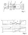
- FIG. 1an exemplary embodiment of a power train of a hybrid vehicle
- FIG. 2a diagram to illustrate a restart of a combustion engine as a function of the time
- FIG. 3a diagram with a characteristic curve of the pilot torque as a function of the time
- FIG. 4a diagram with a characteristic curve of the target acceleration as a function of the difference in speed of rotation between the crankshaft and the rotor, and
- FIG. 5an exemplary embodiment of a control unit for the clutch in the form of a block circuit diagram.
- FIG. 1shows an exemplary embodiment of a power train 1 having a combustion engine 2 with a crankshaft 2 a , an electric machine 3 with a rotor 3 a , and a starting clutch 4 operating between the combustion engine 2 and the electric machine 3 .
- Another clutchwhich is designed as a torque converter 5 in the exemplary embodiment shown, which can have a torque converter lockup clutch in addition, is situated between the transmission 6 and the electric machine 3 .
- the transmission 6transmits the drive torque generated individually or jointly by the drive units in the form of the combustion engine 2 and the electric machine 3 to the drive wheels 7 .
- combustion engine 2is to be the exclusive transmitter of torque when the starting clutch 4 is engaged, the current to the electric machine is shut off; in this case the rotor 3 a serves as centrifugal mass.
- both drive unitstransmit torque to the transmission 6 .
- starting clutch 4is disengaged.
- brakingis to be provided by electric machine 3
- starting clutch 4is disengaged and electric machine 3 is operated as a generator.
- the drag torque of combustion engine 2can be utilized to achieve a greater retarding effect by engaging starting clutch 4 .
- the torque converter lockup clutch of the torque converteris disengaged or a neutral position is set in transmission 6 and starting clutch 4 is disengaged, so that rotor 3 a of electric machine 3 can be accelerated by being supplied with electricity.
- the accelerationproceeds up to a predefined speed. After that the starting clutch is engaged in accordance with the proposed method.
- FIG. 2shows in the upper part the change in the torque M and in the lower part the speed of rotation n over time t.
- Curve 8 with the x marksshows the change in the target torque to be transmitted via starting clutch 4
- curve 10shows the speed of rotation of electric machine 10 .
- the two figures identified with the marksshow in the form of curve 9 the actual torque transmitted via the starting clutch, and in the form of curve 11 the rotational speed of the crankshaft 2 a of combustion engine 2 .
- starting clutch 4transmits no torque, since it is completely disengaged and no target torque is specified.
- Curve 10already shows the accelerated value of the rotational speed of the electric machine with a nearly constant speed value.
- a pre-controlled value of the target torqueis specified to control the clutch.
- the target torqueis converted to an actual torque, which acts on the crankshaft and excites the combustion engine.
- the combustion engineresponds immediately within the prescribed time interval. Hence there is no need to employ an additional elevated target torque in pre-control phase II.
- the determined target torqueis assigned a physical control variable for a clutch actuator, for example a clutch travel checked by a travel sensor system or a contact pressure, in particular when using a hydraulically operated clutch actuating system.
- a clutch actuatorfor example a clutch travel checked by a travel sensor system or a contact pressure, in particular when using a hydraulically operated clutch actuating system.
- the specification of the target torque in regulating phase IIIgives way to acceleration-dependent regulation, in which the target torque is determined depending on the acceleration of the crankshaft 2 a .
- the accelerationcan be determined by evaluating the difference in speed of rotation between crankshaft 2 a and rotor 3 a . It is clear from curve 8 that when the difference in speed of rotation is great at the beginning of regulating phase III a rising target torque is issued, which passes through a maximum and decreases again as the speeds of crankshaft 2 a and rotor 3 a become equalized. The rotational speeds are continuously brought closer to each other by this acceleration regulation.
- an engaged starting clutch 4means a clutch that is engaged up to a maximum transmissible torque, or a clutch that is engaged only to a transmissible torque at which torsional vibrations due to the combustion process of the combustion engine are filtered by partial slippage.
- FIG. 3shows a diagram 12 in which the development of the pre-control torque M(V) over time t is depicted as a possible exemplary embodiment.
- a typical pre-control torque M(V) for the start of a combustion engineat a value of 100%, this value remains constant for a defined time interval—in the range shown, approximately 300 ms. If there are no recognizable signs that the combustion engine has started, for example a detectable speed of rotation at the crankshaft, an ignition impulse or the like, the pre-control torque M(V) is increased by a definable amount, for example 20%. If there is still no beginning start of the combustion engine to be detected, another increase is made, for example by 50% of the initial value.
- the increase in amount of the pre-control torque M(V)can be continued over several of these cycles. After a predefined time limit has been passed, for example after 500 ms in the illustrated case, the starting clutch can be engaged completely. It is understood that the starting value of the pre-control torque M(V) can be adapted to the behavior of the hybrid vehicle, and that the pre-control torque M(V) is increased appropriately starting from this initial value as 100%. It can be beneficial to also make the number of cycles, their amounts of increase and/or the time intervals of the individual amounts dependent on the initial value.
- FIG. 4shows a diagram 13 as an advantageous form for determining a target acceleration a in arbitrary units, depending on the speed difference dn between the rotor of the electric machine and the crankshaft of the combustion engine.
- the target acceleration aincreases in a straight line in a specified interval with the difference in speed of rotation dn, or if the speed difference is negative, for example after a reversal of torque when the combustion engine overtakes the electric machine, it decreases.
- the target acceleration ais capped at a constant value of the target acceleration a despite a continuing increase in the amount of the difference in rotational speed dn.
- the target accelerationcan be stated advantageously in the units 1/min/sec.
- FIG. 5shows an exemplary embodiment of a regulating circuit 14 for regulating the target torque of the starting clutch 4 ( FIG. 1 ) during a starting procedure of the combustion engine 2 .
- the pre-control phase IIFIG. 2
- only the pre-control 15is active, which issues the target torque to be applied to the starting clutch 4 for example corresponding to Diagram 12 described in FIG. 3 .
- the rotational speed signal n(B) for the combustion engine obtained from the hybrid power train 16for example from a rotational speed sensor for the crankshaft, is filtered by means of a filter 17 and transferred to a gradient formation 18 and to the node 19 .
- the speed n(E) of the electric machineis also present there, so that a rotational speed difference dn is forwarded to a unit 20 to determine the target acceleration, for example corresponding to Diagram 13 depicted in FIG. 4 .
- the target acceleration ais offset with the already present actual acceleration a(B), formed from the speed of rotation n(B) in the gradient formation 18 .
- the corresponding control differential a(diff)is sent to a regulator 22 , which is preferably a PI regulator. Regulator 22 then issues a target torque M(a) dependent on the target acceleration a or on the effective control differential a(diff) to the starting clutch 4 ; this target torque is added to the pre-control torque M(V).
Landscapes
- Engineering & Computer Science (AREA)
- Chemical & Material Sciences (AREA)
- Combustion & Propulsion (AREA)
- Transportation (AREA)
- Mechanical Engineering (AREA)
- Automation & Control Theory (AREA)
- Hybrid Electric Vehicles (AREA)
- Hydraulic Clutches, Magnetic Clutches, Fluid Clutches, And Fluid Joints (AREA)
Abstract
Description
| 1 | |||
| 2 | |||
| 2a | crankshaft | ||
| 3 | |||
| 3a | rotor | ||
| 4 | starting clutch | ||
| 5 | |||
| 6 | |||
| 7 | |||
| 8 | |||
| 9 | |||
| 10 | curve | ||
| 11 | |||
| 12 | diagram | ||
| 13 | diagram | ||
| 14 | regulating | ||
| 15 | |||
| 16 | |||
| 17 | |||
| 18 | |||
| 19 | |||
| 20 | |||
| 21 | |||
| 22 | regulator | ||
| a | target acceleration | ||
| a(B) | actual acceleration of combustion engine | ||
| a(diff) | control differential | ||
| dn | rotational speed difference | ||
| M | torque | ||
| M(a) | Acceleration-dependent torque | ||
| M(V) | pre-control torque | ||
| n | rotational speed | ||
| n(B) | speed of combustion engine | ||
| n(E) | speed of electric machine | ||
| t | time | ||
| I | acceleration phase | ||
| II | pre-control phase | ||
| III | regulating phase | ||
| IV | end phase | ||
Claims (9)
Applications Claiming Priority (3)
| Application Number | Priority Date | Filing Date | Title |
|---|---|---|---|
| DE102007031387.1 | 2007-07-05 | ||
| DE102007031387 | 2007-07-05 | ||
| DE102007031387 | 2007-07-05 |
Publications (2)
| Publication Number | Publication Date |
|---|---|
| US20090017988A1 US20090017988A1 (en) | 2009-01-15 |
| US8142328B2true US8142328B2 (en) | 2012-03-27 |
Family
ID=39671770
Family Applications (1)
| Application Number | Title | Priority Date | Filing Date |
|---|---|---|---|
| US12/215,181Expired - Fee RelatedUS8142328B2 (en) | 2007-07-05 | 2008-06-25 | Method for controlling a starting clutch |
Country Status (4)
| Country | Link |
|---|---|
| US (1) | US8142328B2 (en) |
| EP (1) | EP2011681B1 (en) |
| AT (1) | ATE477952T1 (en) |
| DE (2) | DE502008001140D1 (en) |
Cited By (17)
| Publication number | Priority date | Publication date | Assignee | Title |
|---|---|---|---|---|
| US20100056328A1 (en)* | 2006-10-12 | 2010-03-04 | Rene Schenk | Method for controlling a hybrid drive |
| US20110246008A1 (en)* | 2010-03-31 | 2011-10-06 | Aisin Aw Co., Ltd. | Control device |
| US20130012353A1 (en)* | 2011-07-06 | 2013-01-10 | Aisin Aw Co., Ltd. | Control device |
| US8457823B2 (en)* | 2008-12-16 | 2013-06-04 | Robert Bosch Gmbh | Method and device for operating a hybrid vehicle |
| US8517892B2 (en)* | 2011-08-08 | 2013-08-27 | Bae Systems Controls Inc. | Method and apparatus for controlling hybrid electric vehicles |
| US20130288853A1 (en)* | 2011-01-12 | 2013-10-31 | Terufumi Miyazaki | Control device of hybrid vehicle (as amended) |
| US8663062B2 (en) | 2011-08-30 | 2014-03-04 | Aisin Aw Co., Ltd. | Control device |
| US20140100082A1 (en)* | 2012-10-08 | 2014-04-10 | Ford Global Technologies, Llc | Method and system for stopping an engine |
| US20140360793A1 (en)* | 2012-02-29 | 2014-12-11 | Aisin Aw Co., Ltd. | Hybrid drive device |
| US9061681B2 (en) | 2011-07-06 | 2015-06-23 | Aisin Aw Co., Ltd. | Control device |
| US20150197245A1 (en)* | 2013-03-13 | 2015-07-16 | Allison Transmission, Inc. | System and method for detecting vehicle clutch touch point |
| US9114805B2 (en)* | 2011-10-06 | 2015-08-25 | Toyota Jidosha Kabushiki Kaisha | Engine startup system |
| US9175633B2 (en) | 2012-03-20 | 2015-11-03 | Dr. Ing. H.C. F. Porsche Aktiengesellschaft | Engine starting method |
| US20150321658A1 (en)* | 2012-12-07 | 2015-11-12 | Volvo Truck Corporation | Method for engine starting in a hybrid vehicle |
| US9409561B2 (en) | 2014-04-21 | 2016-08-09 | Ford Global Technologies, Llc | Coordinated engine start in hybrid vehicle |
| US10369982B2 (en)* | 2015-07-17 | 2019-08-06 | Ford Global Technologies, Llc | Hybrid vehicle and method of controlling an engine disconnect clutch for engine start-up |
| US10781870B2 (en) | 2017-09-15 | 2020-09-22 | Zf Friedrichshafen Ag | Control unit for a motor vehicle, and method to control the motor vehicle |
Families Citing this family (28)
| Publication number | Priority date | Publication date | Assignee | Title |
|---|---|---|---|---|
| DE102007045367A1 (en)* | 2007-09-22 | 2009-04-02 | Zf Friedrichshafen Ag | Method for operating a drive train |
| DE102007062796A1 (en)* | 2007-12-27 | 2009-07-02 | Robert Bosch Gmbh | Method for operating a hybrid drive device |
| ITBO20090261A1 (en) | 2009-04-28 | 2010-10-29 | Ferrari Spa | METHOD OF STARTING A THERMAL ENGINE OF A HYBRID VEHICLE |
| IT1395448B1 (en) | 2009-09-03 | 2012-09-21 | Ferrari Spa | METHOD OF STARTING A THERMAL ENGINE OF A VEHICLE WITH A HYBRID PROPULSION |
| DE102011006227A1 (en) | 2011-03-28 | 2012-10-04 | Robert Bosch Gmbh | Method for optimizing adjusting process in control system of internal combustion engine of hybrid motor vehicle, involves continuing adjustment of control system after transient oscillation process and after reaching of reference value |
| JP5920354B2 (en)* | 2011-10-12 | 2016-05-18 | トヨタ自動車株式会社 | Control device for vehicle drive device |
| DE102011087943A1 (en)* | 2011-12-08 | 2013-06-13 | Zf Friedrichshafen Ag | Control device of a hybrid vehicle and method for operating the same |
| DE102012007322A1 (en)* | 2012-04-12 | 2013-10-17 | Audi Ag | Method for operating a hybrid drive device |
| JP2014073705A (en)* | 2012-10-02 | 2014-04-24 | Toyota Motor Corp | Vehicular control unit |
| US9067599B2 (en)* | 2013-03-05 | 2015-06-30 | GM Global Technology Operations LLC | Transmission oil pressure control during engine autostart |
| US9242629B2 (en)* | 2013-04-17 | 2016-01-26 | GM Global Technology Operations LLC | Driveline clutch variable clutch capacity reapply, shaping and lash management |
| DE102013009649A1 (en)* | 2013-06-08 | 2014-12-24 | Volkswagen Aktiengesellschaft | Method for controlling and / or regulating a hybrid drive arrangement of a motor vehicle |
| US9393950B2 (en)* | 2013-07-22 | 2016-07-19 | Ford Global Technologies, Llc | Methods and systems for restarting an engine |
| DE112015005375A5 (en) | 2014-11-28 | 2017-08-03 | Schaeffler Technologies AG & Co. KG | Method for starting an internal combustion engine of a hybrid vehicle |
| DE102016218289A1 (en) | 2015-10-06 | 2017-04-06 | Schaeffler Technologies AG & Co. KG | Method for restarting an internal combustion engine of a vehicle at the end of a sailing process |
| DE102016220909A1 (en) | 2015-11-05 | 2017-05-11 | Schaeffler Technologies AG & Co. KG | Method for controlling load changes of a vehicle |
| DE102016213309A1 (en) | 2016-07-21 | 2018-01-25 | Schaeffler Technologies AG & Co. KG | A method of performing a snooping operation of a hydraulic clutch actuator in a hybrid vehicle |
| WO2017202411A1 (en) | 2016-05-27 | 2017-11-30 | Schaeffler Technologies AG & Co. KG | Method for carrying out a snifting operation of a hydraulic clutch actuator in a hybrid vehicle |
| DE102016209939B4 (en) | 2016-06-07 | 2018-04-05 | Schaeffler Technologies AG & Co. KG | Method for avoiding a critical driving situation in a vehicle with a hybrid drive |
| DE102016220220B4 (en)* | 2016-10-17 | 2019-05-16 | Schaeffler Technologies AG & Co. KG | Method for controlling a drive train of a motor vehicle |
| DE102017200982B4 (en)* | 2017-01-23 | 2021-09-16 | Audi Ag | Method for operating a drive device for a motor vehicle and a corresponding drive device |
| WO2019001622A1 (en)* | 2017-06-26 | 2019-01-03 | Schaeffler Technologies AG & Co. KG | METHOD AND CONTROL AND REGULATING DEVICE FOR COMPENSATING A CLUTCH MOMENT OF A HYBRID DISC COUPLING IN ACCORDANCE WITH THE SPEED OF AN ELECTRICAL MACHINE |
| DE102017219852A1 (en) | 2017-11-08 | 2019-05-09 | Zf Friedrichshafen Ag | Method for operating a hybrid powertrain |
| CN108869574B (en)* | 2018-08-29 | 2020-09-11 | 一汽解放汽车有限公司 | Statistical principle-based clutch combination self-adaptive control method |
| JP7201563B2 (en)* | 2019-09-27 | 2023-01-10 | トヨタ自動車株式会社 | CONTROL DEVICE AND CONTROL METHOD FOR HYBRID VEHICLE |
| JP7201564B2 (en) | 2019-09-27 | 2023-01-10 | トヨタ自動車株式会社 | Hybrid vehicle and its control method |
| CN115605382B (en)* | 2020-07-24 | 2025-07-25 | 舍弗勒技术股份两合公司 | Engine starting method |
| CN116476842B (en)* | 2023-05-09 | 2023-09-29 | 青岛理工大学 | Method and device for controlling starting of intelligent agricultural machinery and storage medium |
Citations (40)
| Publication number | Priority date | Publication date | Assignee | Title |
|---|---|---|---|---|
| DE19838853A1 (en) | 1997-08-29 | 1999-03-04 | Aisin Aw Co | Hybrid drive arrangement for vehicle |
| EP0922600A2 (en) | 1997-12-12 | 1999-06-16 | Toyota Jidosha Kabushiki Kaisha | Drive control system for hybrid vehicle with engine start-up mode |
| US5916061A (en)* | 1996-09-27 | 1999-06-29 | Honda Giken Kogyo Kabushiki Kaisha | Control apparatus for clutch of vehicle |
| US6026921A (en)* | 1998-03-20 | 2000-02-22 | Nissan Motor Co., Ltd | Hybrid vehicle employing parallel hybrid system, using both internal combustion engine and electric motor for propulsion |
| US6105743A (en)* | 1994-02-23 | 2000-08-22 | Luk Getriebe-Systeme Gmbh | Method and apparatus for regulating the transmission of torque in power trains |
| US6171212B1 (en)* | 1997-08-26 | 2001-01-09 | Luk Getriebe Systeme Gmbh | Method of and apparatus for controlling the operation of a clutch in the power train of a motor vehicle |
| US6364807B1 (en)* | 2000-06-30 | 2002-04-02 | Ford Global Technologies, Inc. | Control strategy for a hybrid powertrain for an automotive vehicle |
| US20020117860A1 (en)* | 1998-09-09 | 2002-08-29 | Luk Lamellen Und Kupplungsbau Beteiligungs Kg | Power train for a motor vehicle |
| US6558290B2 (en)* | 2001-06-29 | 2003-05-06 | Ford Global Technologies, Llc | Method for stopping an engine in a parallel hybrid electric vehicle |
| US20030110875A1 (en)* | 2000-04-03 | 2003-06-19 | Luk Lamellen Und Kupplungsbau Beteilungs Kg | Gearbox |
| DE10260435A1 (en) | 2002-12-21 | 2004-07-01 | Volkswagen Ag | Controlling motor vehicle hybrid drive involves accelerating with electrical machine, starting engine, accelerating with electrical machine and engine with suitable operation of two clutches |
| DE10260838A1 (en) | 2002-12-23 | 2004-07-15 | Volkswagen Ag | Method and device for controlling a clutch within a motor vehicle drive train |
| US6849026B2 (en)* | 1999-04-21 | 2005-02-01 | Hitachi, Ltd. | Power transmission system of an automobile |
| US20050056513A1 (en)* | 2003-02-20 | 2005-03-17 | Luk Lamellen Und Kupplungsbau Beteiligungs Kg | Method and apparatus for adapting a clutch torque |
| US6889645B2 (en)* | 2000-08-29 | 2005-05-10 | Robert Bosch Gmbh | Method for starting a hybrid drive |
| US20050155803A1 (en)* | 2004-01-15 | 2005-07-21 | Peter Schiele | Method for controlling and regulating a powertrain of a hybrid vehicle and powertrain of a hybrid vehicle |
| US6939265B2 (en)* | 2001-05-21 | 2005-09-06 | Luk Lamellen Und Kupplungsbau Beteiligungs Kg | Method of controlling a motor vehicle with an automated clutch device |
| US6988605B2 (en)* | 2000-09-15 | 2006-01-24 | Robert Bosch Gmbh | Method and device for operating a clutch |
| DE102004032173A1 (en) | 2004-07-02 | 2006-02-02 | Volkswagen Ag | Method for operating a hybrid motor vehicle |
| US7158873B2 (en)* | 2001-01-24 | 2007-01-02 | Luk Lamellen Und Kupplungsbau Beteiligungs Kg | Method of controlling an automated clutch of a vehicle |
| EP1762452A2 (en) | 2005-09-08 | 2007-03-14 | Nissan Motor Co., Ltd. | Engine starting control device and method |
| US20070080005A1 (en)* | 2005-10-06 | 2007-04-12 | Nissan Motor Co., Ltd. | Hybrid vehicle drive control system |
| US20070199790A1 (en)* | 2006-02-16 | 2007-08-30 | Luk Lamellen Und Kupplungsbau Beteiligungs Kg | Process and device for adjusting a friction clutch located in a drive train of a vehicle and actuated by an actuator |
| US7273119B2 (en)* | 2003-12-05 | 2007-09-25 | Nissan Motor Co., Ltd. | Method for starting engine of vehicle with hybrid transmission and apparatus for carrying out the method |
| US7306539B2 (en)* | 2000-06-23 | 2007-12-11 | Luk Lamellen Und Kupplungsbau Beteiligungs Kg | Method and apparatus for the control of characteristic operating values of a power train |
| US7351182B2 (en)* | 2004-10-27 | 2008-04-01 | Aisin Aw Co., Ltd. | Drive apparatus for hybrid vehicle and control method thereof |
| US7367415B2 (en)* | 2005-01-28 | 2008-05-06 | Eaton Corporation | Hybrid electric vehicle engine start technique |
| US7370715B2 (en)* | 2004-12-28 | 2008-05-13 | Ford Global Technologies, Llc | Vehicle and method for controlling engine start in a vehicle |
| US7377344B2 (en)* | 2003-11-14 | 2008-05-27 | Bayerische Motoren Werke Aktiengesellschaft | Hybrid drive system for a motor vehicle |
| US20080189018A1 (en)* | 2005-08-20 | 2008-08-07 | Jurgen Lang | Method for operating a hybrid drive train of a motor vehicle |
| US7426972B2 (en)* | 2004-08-05 | 2008-09-23 | Toyota Jidosha Kabushiki Kaisha | Control device for vehicular drive system |
| US20090011899A1 (en)* | 2007-06-25 | 2009-01-08 | Luk Lamellen Und Kupplungsbau Beteiligungs Kg | Method and device for adjusting the friction coefficient of a friction clutch situated in a hybrid power train |
| US20090037060A1 (en)* | 2006-03-09 | 2009-02-05 | Volvo Technology Corporation | Hybrid powertrain and method for controlling a hybrid powertrain |
| US20090255743A1 (en)* | 2006-11-27 | 2009-10-15 | Luk Lamellen Und Kupplungsbau Beteiligungs Kg | Method and device for adapting a clutch in a hybrid drive train of a vehicle |
| US7637842B2 (en)* | 2007-01-23 | 2009-12-29 | Gm Global Technology Operations, Inc. | Method and apparatus for control of a transmission torque converter clutch |
| US7717248B2 (en)* | 2006-03-09 | 2010-05-18 | Luk Lamellen Und Kupplungsbau Beteiligungs Kg | Process and device for controlling and/or regulating an automated clutch |
| US7770678B2 (en)* | 2005-11-09 | 2010-08-10 | Nissan Motor Co., Ltd. | Hybrid vehicle drive control system |
| US7784575B2 (en)* | 2005-11-07 | 2010-08-31 | Nissan Motor Co., Ltd. | Hybrid vehicle drive control system |
| US7824307B2 (en)* | 2007-06-20 | 2010-11-02 | Toyota Jidosha Kabushiki Kaisha | Control device for vehicle power transmission device |
| US7878281B2 (en)* | 2006-03-29 | 2011-02-01 | Nissan Motor Co., Ltd. | Transmitting state switching control apparatus for hybrid vehicle |
- 2008
- 2008-06-25USUS12/215,181patent/US8142328B2/ennot_activeExpired - Fee Related
- 2008-06-26DEDE502008001140Tpatent/DE502008001140D1/enactiveActive
- 2008-06-26EPEP08011557Apatent/EP2011681B1/ennot_activeNot-in-force
- 2008-06-26ATAT08011557Tpatent/ATE477952T1/enactive
- 2008-06-26DEDE102008030480Apatent/DE102008030480A1/ennot_activeWithdrawn
Patent Citations (50)
| Publication number | Priority date | Publication date | Assignee | Title |
|---|---|---|---|---|
| US6105743A (en)* | 1994-02-23 | 2000-08-22 | Luk Getriebe-Systeme Gmbh | Method and apparatus for regulating the transmission of torque in power trains |
| US5916061A (en)* | 1996-09-27 | 1999-06-29 | Honda Giken Kogyo Kabushiki Kaisha | Control apparatus for clutch of vehicle |
| US6171212B1 (en)* | 1997-08-26 | 2001-01-09 | Luk Getriebe Systeme Gmbh | Method of and apparatus for controlling the operation of a clutch in the power train of a motor vehicle |
| DE19838853A1 (en) | 1997-08-29 | 1999-03-04 | Aisin Aw Co | Hybrid drive arrangement for vehicle |
| US6018198A (en)* | 1997-08-29 | 2000-01-25 | Aisin Aw Co., Ltd. | Hybrid drive apparatus for vehicle |
| EP0922600A2 (en) | 1997-12-12 | 1999-06-16 | Toyota Jidosha Kabushiki Kaisha | Drive control system for hybrid vehicle with engine start-up mode |
| US6077186A (en)* | 1997-12-12 | 2000-06-20 | Toyota Jidosha Kabushiki Kaisha | Internal combustion engine starting drive control system for hybrid vehicle |
| US6026921A (en)* | 1998-03-20 | 2000-02-22 | Nissan Motor Co., Ltd | Hybrid vehicle employing parallel hybrid system, using both internal combustion engine and electric motor for propulsion |
| US7114585B2 (en)* | 1998-09-09 | 2006-10-03 | Luk Lamellen Und Kupplungsbau Beteiligungs Kg | Power train for use in motor vehicles and the like |
| US20020117860A1 (en)* | 1998-09-09 | 2002-08-29 | Luk Lamellen Und Kupplungsbau Beteiligungs Kg | Power train for a motor vehicle |
| US20040173393A1 (en)* | 1998-09-09 | 2004-09-09 | Laszlo Man | Power train for use in motor vehicles and the like |
| US6849026B2 (en)* | 1999-04-21 | 2005-02-01 | Hitachi, Ltd. | Power transmission system of an automobile |
| US20030110875A1 (en)* | 2000-04-03 | 2003-06-19 | Luk Lamellen Und Kupplungsbau Beteilungs Kg | Gearbox |
| US7306539B2 (en)* | 2000-06-23 | 2007-12-11 | Luk Lamellen Und Kupplungsbau Beteiligungs Kg | Method and apparatus for the control of characteristic operating values of a power train |
| US6364807B1 (en)* | 2000-06-30 | 2002-04-02 | Ford Global Technologies, Inc. | Control strategy for a hybrid powertrain for an automotive vehicle |
| US6889645B2 (en)* | 2000-08-29 | 2005-05-10 | Robert Bosch Gmbh | Method for starting a hybrid drive |
| US6988605B2 (en)* | 2000-09-15 | 2006-01-24 | Robert Bosch Gmbh | Method and device for operating a clutch |
| US7158873B2 (en)* | 2001-01-24 | 2007-01-02 | Luk Lamellen Und Kupplungsbau Beteiligungs Kg | Method of controlling an automated clutch of a vehicle |
| US6939265B2 (en)* | 2001-05-21 | 2005-09-06 | Luk Lamellen Und Kupplungsbau Beteiligungs Kg | Method of controlling a motor vehicle with an automated clutch device |
| US6558290B2 (en)* | 2001-06-29 | 2003-05-06 | Ford Global Technologies, Llc | Method for stopping an engine in a parallel hybrid electric vehicle |
| DE10260435A1 (en) | 2002-12-21 | 2004-07-01 | Volkswagen Ag | Controlling motor vehicle hybrid drive involves accelerating with electrical machine, starting engine, accelerating with electrical machine and engine with suitable operation of two clutches |
| DE10260838A1 (en) | 2002-12-23 | 2004-07-15 | Volkswagen Ag | Method and device for controlling a clutch within a motor vehicle drive train |
| US7121390B2 (en)* | 2003-02-20 | 2006-10-17 | Luk Lamellen Und Kupplungsbau Beteiligungs Kg | Method and apparatus for adapting a clutch torque |
| US20050056513A1 (en)* | 2003-02-20 | 2005-03-17 | Luk Lamellen Und Kupplungsbau Beteiligungs Kg | Method and apparatus for adapting a clutch torque |
| US7377344B2 (en)* | 2003-11-14 | 2008-05-27 | Bayerische Motoren Werke Aktiengesellschaft | Hybrid drive system for a motor vehicle |
| US7273119B2 (en)* | 2003-12-05 | 2007-09-25 | Nissan Motor Co., Ltd. | Method for starting engine of vehicle with hybrid transmission and apparatus for carrying out the method |
| DE102004002061A1 (en) | 2004-01-15 | 2005-08-04 | Zf Friedrichshafen Ag | Method for controlling and regulating a drive train of a hybrid vehicle and drive train of a hybrid vehicle |
| US20050155803A1 (en)* | 2004-01-15 | 2005-07-21 | Peter Schiele | Method for controlling and regulating a powertrain of a hybrid vehicle and powertrain of a hybrid vehicle |
| US20070099749A1 (en)* | 2004-07-02 | 2007-05-03 | Volkswagen Aktiengesellschaft | Method for operating a hybrid motor vehicle |
| DE102004032173A1 (en) | 2004-07-02 | 2006-02-02 | Volkswagen Ag | Method for operating a hybrid motor vehicle |
| US7426972B2 (en)* | 2004-08-05 | 2008-09-23 | Toyota Jidosha Kabushiki Kaisha | Control device for vehicular drive system |
| US7351182B2 (en)* | 2004-10-27 | 2008-04-01 | Aisin Aw Co., Ltd. | Drive apparatus for hybrid vehicle and control method thereof |
| US7896114B2 (en)* | 2004-12-28 | 2011-03-01 | Ford Global Technologies, Llc | Method for controlling engine start in a vehicle |
| US7370715B2 (en)* | 2004-12-28 | 2008-05-13 | Ford Global Technologies, Llc | Vehicle and method for controlling engine start in a vehicle |
| US7367415B2 (en)* | 2005-01-28 | 2008-05-06 | Eaton Corporation | Hybrid electric vehicle engine start technique |
| US20080189018A1 (en)* | 2005-08-20 | 2008-08-07 | Jurgen Lang | Method for operating a hybrid drive train of a motor vehicle |
| US20070056784A1 (en)* | 2005-09-08 | 2007-03-15 | Shinichiro Joe | Engine starting control device for a hybrid vehicle |
| EP1762452A2 (en) | 2005-09-08 | 2007-03-14 | Nissan Motor Co., Ltd. | Engine starting control device and method |
| US20070080005A1 (en)* | 2005-10-06 | 2007-04-12 | Nissan Motor Co., Ltd. | Hybrid vehicle drive control system |
| US7784575B2 (en)* | 2005-11-07 | 2010-08-31 | Nissan Motor Co., Ltd. | Hybrid vehicle drive control system |
| US7770678B2 (en)* | 2005-11-09 | 2010-08-10 | Nissan Motor Co., Ltd. | Hybrid vehicle drive control system |
| US20070199790A1 (en)* | 2006-02-16 | 2007-08-30 | Luk Lamellen Und Kupplungsbau Beteiligungs Kg | Process and device for adjusting a friction clutch located in a drive train of a vehicle and actuated by an actuator |
| US20090037060A1 (en)* | 2006-03-09 | 2009-02-05 | Volvo Technology Corporation | Hybrid powertrain and method for controlling a hybrid powertrain |
| US7717248B2 (en)* | 2006-03-09 | 2010-05-18 | Luk Lamellen Und Kupplungsbau Beteiligungs Kg | Process and device for controlling and/or regulating an automated clutch |
| US7878281B2 (en)* | 2006-03-29 | 2011-02-01 | Nissan Motor Co., Ltd. | Transmitting state switching control apparatus for hybrid vehicle |
| US20090255743A1 (en)* | 2006-11-27 | 2009-10-15 | Luk Lamellen Und Kupplungsbau Beteiligungs Kg | Method and device for adapting a clutch in a hybrid drive train of a vehicle |
| US7938209B2 (en)* | 2006-11-27 | 2011-05-10 | Schaeffler Technologies Gmbh & Co. Kg | Method and device for adapting a clutch in a hybrid drive train of a vehicle |
| US7637842B2 (en)* | 2007-01-23 | 2009-12-29 | Gm Global Technology Operations, Inc. | Method and apparatus for control of a transmission torque converter clutch |
| US7824307B2 (en)* | 2007-06-20 | 2010-11-02 | Toyota Jidosha Kabushiki Kaisha | Control device for vehicle power transmission device |
| US20090011899A1 (en)* | 2007-06-25 | 2009-01-08 | Luk Lamellen Und Kupplungsbau Beteiligungs Kg | Method and device for adjusting the friction coefficient of a friction clutch situated in a hybrid power train |
Cited By (26)
| Publication number | Priority date | Publication date | Assignee | Title |
|---|---|---|---|---|
| US20100056328A1 (en)* | 2006-10-12 | 2010-03-04 | Rene Schenk | Method for controlling a hybrid drive |
| US8651998B2 (en)* | 2006-10-12 | 2014-02-18 | Robert Bosch Gmbh | Method for controlling a hybrid drive |
| US8457823B2 (en)* | 2008-12-16 | 2013-06-04 | Robert Bosch Gmbh | Method and device for operating a hybrid vehicle |
| US8712613B2 (en)* | 2010-03-31 | 2014-04-29 | Aisin Aw Co., Ltd. | Control device |
| US20110246008A1 (en)* | 2010-03-31 | 2011-10-06 | Aisin Aw Co., Ltd. | Control device |
| US9108635B2 (en)* | 2011-01-12 | 2015-08-18 | Toyota Jidosha Kabushiki Kaisha | Control device of hybrid vehicle |
| US20130288853A1 (en)* | 2011-01-12 | 2013-10-31 | Terufumi Miyazaki | Control device of hybrid vehicle (as amended) |
| US9061681B2 (en) | 2011-07-06 | 2015-06-23 | Aisin Aw Co., Ltd. | Control device |
| US8668621B2 (en)* | 2011-07-06 | 2014-03-11 | Aisin Aw Co., Ltd. | Control device |
| US20130012353A1 (en)* | 2011-07-06 | 2013-01-10 | Aisin Aw Co., Ltd. | Control device |
| US8517892B2 (en)* | 2011-08-08 | 2013-08-27 | Bae Systems Controls Inc. | Method and apparatus for controlling hybrid electric vehicles |
| US8663062B2 (en) | 2011-08-30 | 2014-03-04 | Aisin Aw Co., Ltd. | Control device |
| US9114805B2 (en)* | 2011-10-06 | 2015-08-25 | Toyota Jidosha Kabushiki Kaisha | Engine startup system |
| US20140360793A1 (en)* | 2012-02-29 | 2014-12-11 | Aisin Aw Co., Ltd. | Hybrid drive device |
| US9180858B2 (en)* | 2012-02-29 | 2015-11-10 | Aisin Aw Co., Ltd. | Hybrid drive device |
| US9175633B2 (en) | 2012-03-20 | 2015-11-03 | Dr. Ing. H.C. F. Porsche Aktiengesellschaft | Engine starting method |
| US9393949B2 (en) | 2012-10-08 | 2016-07-19 | Ford Global Technologies, Llc | Method and system for stopping an engine |
| US9108613B2 (en)* | 2012-10-08 | 2015-08-18 | Ford Global Technologies, Llc | Method and system for stopping an engine |
| US20140100082A1 (en)* | 2012-10-08 | 2014-04-10 | Ford Global Technologies, Llc | Method and system for stopping an engine |
| US20150321658A1 (en)* | 2012-12-07 | 2015-11-12 | Volvo Truck Corporation | Method for engine starting in a hybrid vehicle |
| US9481358B2 (en)* | 2012-12-07 | 2016-11-01 | Volvo Truck Corporation | Method for engine starting in a hybrid vehicle |
| US9381912B2 (en)* | 2013-03-13 | 2016-07-05 | Allison Transmission, Inc. | System and method for detecting vehicle clutch touch point |
| US20150197245A1 (en)* | 2013-03-13 | 2015-07-16 | Allison Transmission, Inc. | System and method for detecting vehicle clutch touch point |
| US9409561B2 (en) | 2014-04-21 | 2016-08-09 | Ford Global Technologies, Llc | Coordinated engine start in hybrid vehicle |
| US10369982B2 (en)* | 2015-07-17 | 2019-08-06 | Ford Global Technologies, Llc | Hybrid vehicle and method of controlling an engine disconnect clutch for engine start-up |
| US10781870B2 (en) | 2017-09-15 | 2020-09-22 | Zf Friedrichshafen Ag | Control unit for a motor vehicle, and method to control the motor vehicle |
Also Published As
| Publication number | Publication date |
|---|---|
| DE502008001140D1 (en) | 2010-09-30 |
| US20090017988A1 (en) | 2009-01-15 |
| EP2011681A3 (en) | 2009-04-15 |
| EP2011681A2 (en) | 2009-01-07 |
| DE102008030480A1 (en) | 2009-01-08 |
| ATE477952T1 (en) | 2010-09-15 |
| EP2011681B1 (en) | 2010-08-18 |
Similar Documents
| Publication | Publication Date | Title |
|---|---|---|
| US8142328B2 (en) | Method for controlling a starting clutch | |
| US9944277B2 (en) | Method for learning engine clutch kiss point of hybrid vehicle | |
| CN101767587B (en) | System and methods for assisted direct start control | |
| US6966868B2 (en) | Method for adapting the adjustment of a clutch in an unconventional drive train of a vehicle | |
| JP5223603B2 (en) | Control device for hybrid vehicle | |
| US8712613B2 (en) | Control device | |
| KR101371461B1 (en) | Method and system for learning and controlling kiss point of engine clutch for hybrid electric vehicle | |
| US8651998B2 (en) | Method for controlling a hybrid drive | |
| US7351182B2 (en) | Drive apparatus for hybrid vehicle and control method thereof | |
| US8186464B2 (en) | Method for operating a parallel hybrid drive | |
| JP5391654B2 (en) | Control device for hybrid vehicle | |
| JP4135107B2 (en) | Hybrid vehicle drive device and control method thereof | |
| JP2010511129A (en) | Method and apparatus for adjusting a clutch in a vehicle hybrid drivetrain | |
| CN106662176A (en) | Method for determining a change in the contact point of a hybrid clutch of a hybrid vehicle and for adapting the friction coefficient thereof | |
| JP2002218602A (en) | Regenerative brake energy recovery method and device parallel hybrid electric vehicle | |
| US9047365B2 (en) | Method and device for monitoring the satisfactory functioning of at least one first and a second component of a vehicle drive train | |
| JP2006123642A (en) | Hybrid vehicle drive device, control method thereof and control device | |
| CN103303310A (en) | Method for operating a vehicle powertrain | |
| CN103748378B (en) | Vehicle control system | |
| JP2009202868A (en) | Adapting method of proportional clutch | |
| WO2014038591A1 (en) | Vehicle drive device control device | |
| JP5359301B2 (en) | Control device for hybrid vehicle | |
| JP5843833B2 (en) | Vehicle control device | |
| KR100925955B1 (en) | Clutch characteristic correction device of hybrid vehicle | |
| CN103223939A (en) | Method for controlling a transmission coupled to an engine that may be automatically stopped |
Legal Events
| Date | Code | Title | Description |
|---|---|---|---|
| AS | Assignment | Owner name:LUK LAMELLEN UND KUPPLUNGSBAU BETEILIGUNGS KG, GER Free format text:ASSIGNMENT OF ASSIGNORS INTEREST;ASSIGNOR:REUSCHEL, MICHAEL;REEL/FRAME:021555/0151 Effective date:20080701 | |
| AS | Assignment | Owner name:LUK VERMOEGENSVERWALTUNGSGESELLSCHAFT MBH, GERMANY Free format text:MERGER;ASSIGNOR:LUK LAMELLEN UND KUPPLUNGSBAU BETEILIGUNGS KG;REEL/FRAME:027727/0719 Effective date:20100701 | |
| AS | Assignment | Owner name:SCHAEFFLER TECHNOLOGIES AG & CO. KG, GERMANY Free format text:ASSIGNMENT OF ASSIGNORS INTEREST;ASSIGNOR:LUK VERMOEGENSVERWALTUNGSGESELLSCHAFT MBH;REEL/FRAME:027722/0317 Effective date:20120217 | |
| STCF | Information on status: patent grant | Free format text:PATENTED CASE | |
| FPAY | Fee payment | Year of fee payment:4 | |
| AS | Assignment | Owner name:SCHAEFFLER TECHNOLOGIES AG & CO. KG, GERMANY Free format text:CHANGE OF NAME;ASSIGNOR:SCHAEFFLER TECHNOLOGIES GMBH & CO. KG;REEL/FRAME:037732/0347 Effective date:20150101 Owner name:SCHAEFFLER TECHNOLOGIES GMBH & CO. KG, GERMANY Free format text:MERGER AND CHANGE OF NAME;ASSIGNORS:SCHAEFFLER TECHNOLOGIES AG & CO. KG;SCHAEFFLER VERWALTUNGS 5 GMBH;REEL/FRAME:037732/0228 Effective date:20131231 | |
| AS | Assignment | Owner name:SCHAEFFLER TECHNOLOGIES AG & CO. KG, GERMANY Free format text:CORRECTIVE ASSIGNMENT TO CORRECT THE PROPERTY NUMBERS PREVIOUSLY RECORDED ON REEL 037732 FRAME 0347. ASSIGNOR(S) HEREBY CONFIRMS THE APP. NO. 14/553248 SHOULD BE APP. NO. 14/553258;ASSIGNOR:SCHAEFFLER TECHNOLOGIES GMBH & CO. KG;REEL/FRAME:040404/0530 Effective date:20150101 | |
| FEPP | Fee payment procedure | Free format text:MAINTENANCE FEE REMINDER MAILED (ORIGINAL EVENT CODE: REM.); ENTITY STATUS OF PATENT OWNER: LARGE ENTITY | |
| LAPS | Lapse for failure to pay maintenance fees | Free format text:PATENT EXPIRED FOR FAILURE TO PAY MAINTENANCE FEES (ORIGINAL EVENT CODE: EXP.); ENTITY STATUS OF PATENT OWNER: LARGE ENTITY | |
| STCH | Information on status: patent discontinuation | Free format text:PATENT EXPIRED DUE TO NONPAYMENT OF MAINTENANCE FEES UNDER 37 CFR 1.362 | |
| FP | Lapsed due to failure to pay maintenance fee | Effective date:20200327 |