US8142323B2 - Continuously variable transmission - Google Patents
Continuously variable transmissionDownload PDFInfo
- Publication number
- US8142323B2 US8142323B2US11/910,450US91045006AUS8142323B2US 8142323 B2US8142323 B2US 8142323B2US 91045006 AUS91045006 AUS 91045006AUS 8142323 B2US8142323 B2US 8142323B2
- Authority
- US
- United States
- Prior art keywords
- pinion
- output
- gear
- shaft
- rotation
- Prior art date
- Legal status (The legal status is an assumption and is not a legal conclusion. Google has not performed a legal analysis and makes no representation as to the accuracy of the status listed.)
- Active, expires
Links
Images


Classifications
- F—MECHANICAL ENGINEERING; LIGHTING; HEATING; WEAPONS; BLASTING
- F16—ENGINEERING ELEMENTS AND UNITS; GENERAL MEASURES FOR PRODUCING AND MAINTAINING EFFECTIVE FUNCTIONING OF MACHINES OR INSTALLATIONS; THERMAL INSULATION IN GENERAL
- F16H—GEARING
- F16H37/00—Combinations of mechanical gearings, not provided for in groups F16H1/00 - F16H35/00
- F16H37/02—Combinations of mechanical gearings, not provided for in groups F16H1/00 - F16H35/00 comprising essentially only toothed or friction gearings
- F16H37/06—Combinations of mechanical gearings, not provided for in groups F16H1/00 - F16H35/00 comprising essentially only toothed or friction gearings with a plurality of driving or driven shafts; with arrangements for dividing torque between two or more intermediate shafts
- F16H37/08—Combinations of mechanical gearings, not provided for in groups F16H1/00 - F16H35/00 comprising essentially only toothed or friction gearings with a plurality of driving or driven shafts; with arrangements for dividing torque between two or more intermediate shafts with differential gearing
- F16H37/0833—Combinations of mechanical gearings, not provided for in groups F16H1/00 - F16H35/00 comprising essentially only toothed or friction gearings with a plurality of driving or driven shafts; with arrangements for dividing torque between two or more intermediate shafts with differential gearing with arrangements for dividing torque between two or more intermediate shafts, i.e. with two or more internal power paths
- F16H37/084—Combinations of mechanical gearings, not provided for in groups F16H1/00 - F16H35/00 comprising essentially only toothed or friction gearings with a plurality of driving or driven shafts; with arrangements for dividing torque between two or more intermediate shafts with differential gearing with arrangements for dividing torque between two or more intermediate shafts, i.e. with two or more internal power paths at least one power path being a continuously variable transmission, i.e. CVT
- F16H37/086—CVT using two coaxial friction members cooperating with at least one intermediate friction member
- F—MECHANICAL ENGINEERING; LIGHTING; HEATING; WEAPONS; BLASTING
- F16—ENGINEERING ELEMENTS AND UNITS; GENERAL MEASURES FOR PRODUCING AND MAINTAINING EFFECTIVE FUNCTIONING OF MACHINES OR INSTALLATIONS; THERMAL INSULATION IN GENERAL
- F16H—GEARING
- F16H37/00—Combinations of mechanical gearings, not provided for in groups F16H1/00 - F16H35/00
- F16H37/02—Combinations of mechanical gearings, not provided for in groups F16H1/00 - F16H35/00 comprising essentially only toothed or friction gearings
- F16H37/06—Combinations of mechanical gearings, not provided for in groups F16H1/00 - F16H35/00 comprising essentially only toothed or friction gearings with a plurality of driving or driven shafts; with arrangements for dividing torque between two or more intermediate shafts
- F16H37/08—Combinations of mechanical gearings, not provided for in groups F16H1/00 - F16H35/00 comprising essentially only toothed or friction gearings with a plurality of driving or driven shafts; with arrangements for dividing torque between two or more intermediate shafts with differential gearing
- F16H37/0833—Combinations of mechanical gearings, not provided for in groups F16H1/00 - F16H35/00 comprising essentially only toothed or friction gearings with a plurality of driving or driven shafts; with arrangements for dividing torque between two or more intermediate shafts with differential gearing with arrangements for dividing torque between two or more intermediate shafts, i.e. with two or more internal power paths
- F16H37/084—Combinations of mechanical gearings, not provided for in groups F16H1/00 - F16H35/00 comprising essentially only toothed or friction gearings with a plurality of driving or driven shafts; with arrangements for dividing torque between two or more intermediate shafts with differential gearing with arrangements for dividing torque between two or more intermediate shafts, i.e. with two or more internal power paths at least one power path being a continuously variable transmission, i.e. CVT
- F16H2037/088—Power-split transmissions with summing differentials, with the input of the CVT connected or connectable to the input shaft
- F16H2037/0886—Power-split transmissions with summing differentials, with the input of the CVT connected or connectable to the input shaft with switching means, e.g. to change ranges
Definitions
- the present inventionrelates to a continuously variable transmission which incorporates a continuously variable ratio device (“variator”) and is able to produce a range of output gearing ratios wider than the range provided by the variator using a planetary gear mechanism and employing power recirculation. More specifically, it relates to a continuously variable transmission in which the input shaft and the output shaft are coaxially disposed.
- the said continuously variable transmission 1incorporates: a toroidal race, rolling traction variator 5 comprising an input disc 2 , an output disc 3 and rollers 4 which are disposed between these two discs and which are able to alter their position of radial contact with the two discs; a planetary gear mechanism 6 having a carrier C 1 supporting three pinions P 1 , P 2 and P 3 mutually spaced along the axial direction; a reversing gear mechanism 7 having a cattier C 2 supporting two pinions P 4 and P 5 which are spaced along the axial direction; and a high/low regime change mechanism 10 comprising a low brake L able to stop a sun gear S 4 on the output side of the reversing gear mechanism, and a high clutch H interposed between a second sun gear (high-mode output gear) S 2 of
- the known continuously variable transmission 1uses the planetary gear mechanism 6 to combine the rotations of the carrier C 1 (directly inputting the rotation of the input shaft 12 ) and the sun gear S 1 on the input side, which has been reversed and geared via the directly inputting carrier CT and variator 5 , and outputs the result to a low-mode output gear (third sun gear) S 3 .
- the planetary gear mechanism 6also reverses the rotation of the said output gear S 3 and outputs the result to the output shaft 13 .
- the low/high regime change mechanism 10may also be configured using a low clutch L interposed between a carrier C 2 and the output shaft 13 , and a high clutch H similar to the one above interposed between the second sun gear S 2 of the planetary gear and the output shaft 13 .
- the known continuously variable transmissionhas large axial length since the planetary gear mechanism 6 comprises three pinions P 1 , P 2 and P 3 which are separated along the axial direction, and the reversing gear mechanism 7 also comprises two pinions P 4 and P 5 which are separated along the axial direction.
- the inventors of the present patent applicationhave devised a continuously variable transmission which uses a dual planetary gear in the reversing gear mechanism and allows for shortening in the axial direction.
- a continuously variable transmissioncomprising a toroidal-race continuously variable ratio device (“variator”), a planetary gear mechanism, a reversing gear mechanism, and a low/high regime change mechanism, the variator having a rotary input and a rotary output, the rotary input of the variator being drivably coupled to an input shaft of the CVT, characterised in that:
- the planetary gear mechanismcomprises two trains of planetary gears and has four external coupling elements, namely a first element, a second element, a third element and a fourth element;
- the first elementis drivably coupled to the input shaft so that its rotation is determined by that of the input shaft
- the second elementis drivably coupled to the rotary output of the variator so that its rotation is determined by the variator's output speed and results from a reversal of the rotational direction of the input shaft of the CVT and a continuously variable speed change produced by the variator; in a low regime mediated by the low/high regime change mechanism, the third element is drivingly coupled to an output shaft of the CVT, the rotation of the third element being reversed by means of the reversing gear mechanism, and in a high regime mediated by the low/high regime change mechanism, the fourth element is drivingly coupled to the output shaft of the CVT.
- the pinion shaftneed only have a short arrangement for supporting two trains of pinions in the axial direction, and, as a result, the bearing which supports the two trains of pinions in a freely rotatable fashion can also have a large diameter and the life capacity of the bearing can be improved, in addition to which flexing of the pinion shaft can be reduced thereby reducing accompanying load fluctuation on the bearing, and the pinion weight also becomes lighter, so that centrifugal loading is reduced, and these together can improve the precision of support of the pin ions and can maintain this high precision over a long period of time.
- the continuously variable transmissioncan be compactly arranged by shortening the planetary gear mechanism in the axial direction.
- the planetary gear mechanismis of Ravigneaux type, which has proved of practical worth as a 2-train/4-element type of mechanism. It follows that it can be shortened in the axial direction and thus the continuously variable transmission can be compactly arranged and its reliability improved.
- CVTcontinuously variable transmission
- variablecontinuously variable ratio device
- planetary gear mechanisma planetary gear mechanism
- reversing gear mechanisma low/high regime change mechanism
- the planetary gear mechanismhas a carrier having a first pinion shaft and a second pinion shaft, a first sun gear, a second sun gear, and a ring gear, the first pinion shaft supports a first pinion and a second pinion which rotate together, the second pinion shaft supports a third pinion, and the first pinion or the second pinion meshes with the third pinion,
- the carrierreceives rotational input from an input shaft, and the first sun gear receives the variator's output rotation, which results from reversal and speed change of the rotation of the input shaft produced by the variator;
- the rotation of the second sun gearis output to the output shaft.
- the planetary gear mechanismcomprises what is known as a Ravigneaux type of planetary gear
- the first planetary shaftneed only have a short arrangement supporting the first pinion and the second pinion, and because the ring gear constitutes a low-regime output gear, it follows that there is little effect on the second pinion shaft, designed to give a gear ratio for achieving the function of continuously variable transmission (CVT) accompanied by power recirculation employing gear shifting in both the underdrive and overdrive directions of the variator, and that a second pinion shaft having a relatively large diameter can be employed.
- CVTcontinuously variable transmission
- the bearing which supports the first and second pinions in a freely rotatable fashioncan also have a large diameter and the bearing life capacity is improved and, by using a second pinion shaft which is highly rigid and a short and stout arrangement, flexing of the said shaft is reduced thereby reducing accompanying load fluctuation on the bearing, in addition to which the pinion weight also becomes lighter and the centrifugal loading is reduced, and these together can improve the prevision of support of the pinions and can maintain this high precision over a long period of time.
- the transmissioncan be compactly arranged by shortening the planetary gear mechanism in the axial direction.
- compact and uncomplicated couplingcan be achieved by coupling the input shaft and the input disc of the variator to a carrier, and coupling the output disc of the variator to a first sun gear, thereby configuring the central part of the variator from a double shaft.
- the reversing gear mechanismcomprises a dual planetary gear having a carrier supporting a first and a second pinion which mesh with each other, a sun gear which meshes with the first pinion, and a ring gear which meshes with the abovementioned second pinion, and the ring gear of the planetary gear mechanism is coupled to one or other of the carrier and sun gear of the reversing gear mechanism, and, in the low regime, with the ring gear stopped, one of the carrier and the sun gear transmits the rotation of the other to the output shaft.
- the reversing gear mechanismcomprises a dual planetary gear, it follows that the said reversing gear mechanism can be shortened in the axial direction thereby rendering the transmission even more compact and, in particular, shortening it in the axial direction.
- the variatorhas two input discs, an output disc or a back-to-back pair of output discs positioned between the input discs, and rollers sandwiched between the input discs and output discs, and the two input discs, the input shaft and the carrier of the abovementioned planetary gear mechanism are arranged to collectively sustain thrust forces, and the first and second sun gears are also supported in the thrust direction via thrust bearings, with respect to the integrally arranged carrier or input shaft
- FIG. 1is a schematic diagram showing the configuration of a continuously variable transmission according to the present invention.
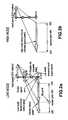
- FIG. 2is a speed diagram showing (a) the low regime and (b) the high regime.
- FIG. 3is a graph showing the relationship between the speed ratio of the variator and the speed ratio of the transmission.
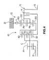
- FIG. 4is a schematic diagram of a partially modified embodiment of the present invention.
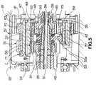
- FIG. 5is a cross-section showing the main parts of an embodiment of the present invention.
- FIG. 6is a schematic diagram showing prior art, in which (a) and (b) show partly different types.
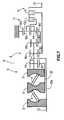
- FIG. 7is a schematic diagram showing technology constituting background to the present invention which the present inventors devised based on the abovementioned prior art.
- FIG. 8is a speed diagram showing (a) the low regime and (b) the high mode regime.
- FIG. 9is a cross-section showing the arrangement of the main parts of the abovementioned background technology.
- the toroidal type variator 5 and the planetary gear mechanism 6are the same as described above, but the reversing gear mechanism 7 1 comprises a dual planetary gear.
- the carrier C 0supports the pinions P 4 and P 5 , which mesh with each other, in a freely rotatable fashion, and one of the pinions P 4 meshes with the sun gear S 0 while the other pinion P 5 meshes with the ring gear R 0 , in addition to which the sun gear S 0 is coupled with a third sun gear (low-mode output gear) S 3 of the abovementioned planetary gear mechanism 6 , the ring gear R 0 is fixed to the casing 15 , and the carrier C 0 is coupled via the low clutch L to the output shaft 13 .
- the FIG. 7 transmission 1 1operates as shown in the speed diagram of FIG. 8 . More specifically, as shown in FIG. 8 ( a ), in the low regime (in which the low clutch L is engaged and the high clutch H is disengaged), rotation of the input shaft 12 (for example engine-output rotation) is transmitted to the carrier C 1 of the planetary gear mechanism 6 via a central shaft 12 a and is reversed via the toroidal type variator 5 before being transmitted to the first sun gear (input gear) S 1 .
- the rotation of the said the output gear S 3is transmitted to the input sun gear S 0 of the reversing gear mechanism 7 1 , which is integral therewith, and, since the ring gear R 0 is locked, rotation is reversed before being output from the carrier C 0 .
- the rotation of the said carrier C 0is transmitted via the low clutch L, which is engaged with the output shaft 13 . Consequently, the backward rotation of the output gear S 3 becomes forward rotation at the carrier C 0 and the output shaft 13 .
- the differential device of the downstream power-transmission side of the transmission 1 1has an intervening re-reversing mechanism (not depicted) and the forward rotation of the abovementioned output shaft 13 becomes rotational output for rearward travel of the vehicle.
- the output shaft (carrier C 0 ) 13changes gearing from rearward-travel rotation, through the GN point (zero rotation) and into forward-travel rotation.
- the systemchanges over to high regime.
- the rotation of the second sun gear (the high-mode output gear) S 2 of the planetary gear mechanism 6is output without any alteration, via the high clutch H, to the output shaft 13 .
- the rotation of the input shaft 12is directly transmitted to the carrier C 1 of the planetary gear mechanism 6 , and is reversed by the variator 5 before being transmitted to the first sun gear (input gear) S 1 .
- the fixed-speed forward rotation of the abovementioned carrier C 1 and the reversed and geared rotation of the first sun gear S 1are combined by the planetary gear mechanism 6 , and the result is output from the second sun gear S 2 , and, here, the input-side gear ratio (S 1 /P 1 ) and the output-side gear ratio (S 2 /P 2 ) are close values or the same value, and the gear ratio of the variator 5 constitutes the output speed after having been shifted in the backward-rotation direction by an amount roughly corresponding to the forward-travel output speed at the time of maximum UD of the variator in the abovementioned low mode.
- the variator 5when the variator 5 is in the maximum UD state, the second sun gear (output gear) S 2 is at its minimum forward-travel output speed in the high mode, the variator 5 shifts gearing from the UD side to the OD side and, as it does so, the forward-travel output speed increases.
- the backward rotation sidecorresponds to the forward-travel direction due to the re-reversing mechanism.
- the present transmission 11is at the maximum speed for rearward travel and, as the variator 5 changes gearing in the UD direction, the system passes through the geared neutral (GN) point and enters the forward-travel state, increasing speed in the forward-travel direction until, in the maximum UD position of the variator 5 , the maximum output speed for forward travel in the low regime is reached, at which time the system changes over to the high regime whereupon, with the variator 5 in the maximum UD position, the system is at the minimum output speed being roughly the same as the abovementioned maximum output speed in the low regime.
- the forward-travel output speedalso increases and, in the maximum OD position of the variator 5 , the maximum output speed for forward travel is reached.
- the transmission 1is shifted from rearward travel, through geared neutral and into the forward-travel direction and, by shifting the variator 5 from the UD position in the OD direction, it continues further to increase in speed in the forward-travel direction until it reaches the maximum output speed.
- the transmission 1 1 shown in FIG. 7does allow for shortening in the axial direction through the use of a dual planetary gear in the reversing gear mechanism, but the planetary gear mechanism 6 used for combining the torques is one having 3 pinions in the axial direction (3 step pinion) similarly to the known transmission 1 shown in FIG. 6 .
- FIG. 9shows a section through the type of transmission schematically represented in FIG. 7 , having a carrier C 1 supporting, linearly in the axial direction, three pinions P 1 , P 2 and P 3 ; a first sun gear (input gear) S 1 meshing with the first pinion P 1 ; a second sun gear (high-mode output gear) S 2 meshing with the second pinion P 2 ; and a third sun gear (low-mode output gear) S 3 meshing with the third pinion P 3 .
- the carrier C 1has a carrier main-body 21 a integrally formed with one of the discs 2 of the variator 5 , and a carrier cover 21 b integral with the said main-body.
- the carrier main-body 21 ais supported, with freedom of rotation via a bearing 24 , on a transmission casing 22 . Further, the said carrier main-body 21 a and cover 21 b are provided with a pinion shaft 23 which supports, with freedom of rotation via needle bearings 29 or a bush, the abovementioned integrally formed first, second and third pinions P 1 , P 2 and P 3 . It will be appreciated that references to a bearing also include a bush.
- the first sun gear S 1is formed at the front-end part of a hollow shaft 25 , and the base part of the said hollow shaft 25 is coupled to the central output disc 3 (see FIG. 7 ) of the abovementioned variator 5 .
- an input shaft (central shaft) 12is supported with freedom of rotation by means of needle bearings or the like, and the said input shaft 12 is coupled to an engine output shaft via a damper as its base part (towards the front of the vehicle), and is spline-connected with the abovementioned carrier main-body 21 a at its front-end part (towards the back of the vehicle).
- the second sun gear S 2is formed on an intermediate shaft 26 , and the said intermediate shaft 26 is coupled to the high clutch H of the abovementioned low/high regime change mechanism (see FIG. 7 ).
- the third sun gear S 3is formed on a sleeve 27 fitted with freedom of rotation over the abovementioned intermediate shaft 26 , and the said sleeve 27 is coupled to the sun gear S 0 (see FIG. 7 ) of the abovementioned reversing gear mechanism.
- the abovementioned pinion shaft 23supports the three pinions P 1 , P 2 and P 3 formed integrally and linearly in the axial direction, it entails an arrangement which is long in the axial direction and, as described hereinabove, since gear shifting continues with both the forward-travel maximum output speed in low mode and the forward-travel minimum output speed in high mode roughly coincident at the maximum UD of the variator 5 , the gear diameter of the third pinion gear P 3 is reduced and thus the diameter of the pinion shaft 23 is also small.
- the arrangement of the planetary gear mechanism 6is disadvantageous in terms of loadings such as centrifugal loading, in that the three integrally formed pinions P 1 , P 2 and P 3 are heavy and the cagier C 1 experiences substantial centrifugal loading.
- the planetary gear mechanism 6is long in the axial direction and, even if an attempt is made to shorten the reversing gear mechanism, the transmission per se remains long in the axial direction.
- FIG. 1shows a transmission 1 2 embodying the present invention. It comprises a continuously variable device (“variator”) 5 , a planetary gear mechanism 6 1 , a reversing gear mechanism 7 1 and a low/high change-over mechanism 10 .
- the variator 5is a toroidal-race, rolling-traction device which has two input discs 2 and 2 coupled to an input shaft 12 , a single output disc 3 coupled to a hollow shaft 25 and power rollers 4 and 4 held sandwiched between the two discs.
- the input discs 2 and the output disc 3have concave hollows 2 a and 3 a in the shape of arcs forming part of a circle in such a way that they face each other to form a double cavity sandwiching the two trains of power rollers 4 and 4 .
- the power rollers 4 and 4can continuously change gear by being made to incline by being shifted in the directions perpendicular to their axes, so altering their radius of contact with the input discs 2 and the output disc 3 .
- the present variator 5has a speed ratio (output speed/input speed) of from ⁇ 0.4 to ⁇ 2.5. It will be appreciated that the speed ratio is “ ⁇ ” (negative) since the output disc 3 turns in reverse relative to the input discs 2 .
- the planetary gear mechanism 6 1comprises a 2-train/4-element type of planetary gear having 2 axially displaced trains of planetary gears and 4 external coupling elements. It preferably comprises a Ravigneaux type of planetary gear having a single simple planetary gear and a single dual planetary gear.
- the said planetary gear mechanism 6 1has a carrier (first element) C supporting a long pinion shaft and a short pinion shaft, and it supports two pinions P 1 and P 2 in series in the axial direction with freedom of rotation on the long pinion shaft, and supports a single pinion P 3 with freedom of rotation on the short pinion shaft.
- the said carrier Cis coupled to the input shaft 12 and is also coupled to one of the output discs 2 , and the said carrier C is coupled to the input shaft 12 and to the output disc 2 integral therewith such that fixed-speed rotation is transmitted.
- a first sun gear (second element) S 1which is coupled to the output disc 3 of the variator 5 , meshes with the first pinion P 1 , and the said first sun gear S 1 constitutes an input gear for inputting geared rotation from the variator 5 .
- the second pinion P 2 and the third pinion P 3mesh with each other and are disposed in the same plane (overlapping with each other in the axial direction), and the second pinion P 2 meshes with a second sun gear S 2 while the third pinion P 3 meshes with a ring gear R 3 .
- the second sun gear (fourth element) S 2is coupled, via the high clutch H of the low/high regime change mechanism 10 , to an output shaft 13 so as to constitute a high-mode output gear.
- the ring gear (third element) R 3is coupled to a carrier C 0 of the reversing gear mechanism 7 1 so as to constitute a low-mode output gear.
- the reversing gear mechanism 7 1comprises a dual planetary gear having two pinions (a first pinion P 4 and a second pinion P 5 ) which mesh with each other, and the carrier C 0 thereof is coupled to the ring gear R 3 as described hereinabove, while a ring gear R 0 is fixed to a casing 22 , and a sum gear S 0 is coupled via a roller clutch L to the output shaft 13 .
- the present continuously variable transmission (CVT) 12operates in the way shown by the gearing diagram of FIG. 2 .
- the speed diagram of FIG. 2shows the first and the second pinions P 1 and P 2 as being a common long pinion, the gear ratios S 1 /P 1 and S 2 /P 2 as being the same, and the output speed and the variator output line as overlapping, it goes without saying that the abovementioned gear ratios (S 1 /P 1 ) and (S 2 /P 2 ) may be changed such that the output speed and the variator output line do not overlap as shown in the speed diagram shown in FIG. 8 .
- torquecan be distributed at a gear ratio which is better for transmission efficiency as compared with the variator and that the efficiency of the transmission as a whole can be improved by changing the gear ratios S 1 /P 1 and S 2 /P 2 .
- gear ratios S 1 /P 1 and S 2 /P 2are the same, fuel consumption in the high-speed operating region can be improved by increasing the speed of the output gear S 2 in the high mode, and using more highly geared ratios in the transmission as a whole.
- the second sun gear R 2rotates idly since the high clutch H is disengaged.
- the output ring gear R 3goes from reverse rotation to the geared neutral position (GN point) which is to say the position in which the output speed is 0 and torque is limitlessly dissipated, and, upon further changing gear to the OD side, it increases in speed to the positive rotation side (the same direction as rotation of the input shaft).
- the rotation of the said output ring gear R 3is directly transmitted to the carrier C 0 of the reversing gear mechanism 7 1 , and is reversed due to the stopping of the ring gear RD and output from the sun gear S 0 .
- the rotations of the abovementioned output ring gear R 3 and the carrier C 0are reversed, and backward rotation of the output ring gear R 3 is output as rear-ward-travel output speed at the sun gear S 0 , while positive rotation of the output ring gear R 3 is output as forward-travel output speed at the sun gear S 0 .
- the systemswitches to high regime.
- rotation of the input shaft 12is directly transmitted to the carrier C of the planetary gear mechanism 6 1 , while the geared rotation resulting after reversal by the variator 5 is transmitted to the first sun gear S 1 , and these are combined by the said planetary gear mechanism 6 1 .
- the resultis output from the second sun gear S 2 which is the high regime output gear.
- the abovementioned second sun gear S 2outputs rotation which is the same as the geared output rotation (variatior gear ratio) from the variator 5 , and the said variator gear ratio is output as a high regime forward-travel output speed from the output shaft 13 due to the connection of the high clutch H.
- the speed ratio of the continuously variable transmission 12continues to increase in the backward-rotation direction and, when the variator 5 reaches the UD end (about ⁇ 0.4), the speed ratio of the continuously variable transmission 1 2 is about ⁇ 0.5.
- the systemchanges over to the high regime.
- the speed ratio of the variator 5when the speed ratio of the variator 5 is at the abovementioned UD end, the speed ratio of the continuously variable transmission 12 is at a value (about ⁇ 0.5) which is the same as in the abovementioned low mode, and here, if the speed ratio of the variator 5 is changed from the abovementioned UD end continuously in the OD direction, then the speed ratio of the continuously variable transmission 1 2 increases from the abovementioned low regime continuously in the backward-rotation direction.
- the speed ratio of the variator 5when, continuing on from changing the gearing of the variator 5 in the OD direction, the speed ratio of the variator 5 reaches the OD end (about ⁇ 2.5), the speed ratio of the continuously variable transmission 1 2 is about ⁇ 2.75 which is the maximum speed ratio.
- the gearing of the variator 5can be changed from the OD end to the UD direction such that the speed of the automobile gradually increases as it goes from rearward travel, through geared neutral (GN) and into forward travel, in addition to which, at the UD end of the variator 5 the system changes over into high regime and the gearing of the variator 5 changes from the UD end to the OD direction such that the speed of the automobile continues to increase in the direction of forward travel.
- GNgeared neutral
- FIG. 4shows a partly modified gear train in which the reversing gear mechanism 72 similarly comprises a dual planetary gear but the ring gear R 0 is coupled to a low brake L and the carrier C 0 is directly coupled to the output shaft 13 . Also the low regime output ring gear R 3 of the planetary gear mechanism 6 1 is coupled to the sun gear S 0 of the reversing gear mechanism 72 , and the high clutch H is interposed between the high regime output gear S 0 of the planetary gear and the output shaft 13 .
- FIG. 5is a cross-sectional diagram showing a planetary gear according to the present invention.
- the planetary gear mechanism 6 1is of Ravigneaux type, comprising 2 trains consisting of a simple planetary gear 31 and a dual planetary gear 32 .
- the said planetary gear mechanism 61has a carrier C supporting a first pinion P 1 , a second pinion P 2 and a third pinion P 3 ; a first sun gear (input gear) S 1 meshing with the first pinion P 1 ; a second sun gear (high-mode output gear) S 2 meshing with the second pinion P 2 ; and a low-mode output ring gear R 3 meshing with the third pinion P 3 .
- the carrier Ccomprises a carrier main-body 33 and a carrier cover 35 integrally connected with the said main-body, and the carrier main-body 33 is supported with freedom to rotate via a bearing 24 on a transmission casing 22 , and is also coupled to one of the output discs 2 of the variator 5 , in addition to which it is spline-connected and fastened by a nut 34 to the input shaft 12 which extends through the centre of the variator 5 .
- a first pinion shaft 36which is shared by both the abovementioned simple and dual planetary gears 31 and 32 , and a second shorter pinion shaft 37 used by the dual pinion 32 are provided, and are prevented from revolving, across the abovementioned carrier main body 33 and carrier cover 35 .
- the first pinion P 1 and the second pinion P 2are supported next to each other in the axial direction on the first pinion shaft 36 , while the third pinion P 3 is supported on the second pinion shaft 37 .
- the first pinion P 1 and the second pinion P 2are integrally formed, and, although they need not necessarily have the same number of teeth, in the present embodiment they have the same number of teeth, and the shared pinions P 1 and P 2 are supported with freedom of rotation on the abovementioned first pinion shaft 36 via needle bearings 37 and 37 (or a bush).
- the third pinion P 3is supported with freedom of rotation via needle bearings 39 (or a bush) on the abovementioned second pinion shaft 37 .
- the abovementioned first sun gear S 1is formed on the front-end portion of a hollow shaft 25 , and the said hollow shaft 25 is supported with freedom of rotation over the input shaft 12 . At its base-end portion it is coupled to the output disc 3 of the variator 5 .
- the second sun gear S 2is formed on the base-end part of an intermediate shaft 26 , and the said intermediate shaft 26 is supported with freedom of rotation with its base-end portion fitted over the input shaft 12 , while to its front-end (to the rear), it is connected to the high clutch H of the low/high regime change mechanism 10 .
- the output ring gear R 3cannot be pulled off but is fixed, via a ring-shaped splined member 41 , on the carrier flange 40 of the reversing gear mechanism 7 1 .
- the respective thrust bearings 42 and 43are interposed between the front and rear side surfaces of the spline-coupled part 33 a of the abovementioned carrier main-body 33 and the rear-end surface of the hollow shaft 25 and front-end surface of the intermediate shaft 26 , and a thrust bearing 45 is interposed between the rear-end surface of the intermediate shaft 26 , in the portion where the second sun gear S 2 is formed, and the front end of the sun gear S 0 of the reversing gear mechanism 7 1 .
- the input shaft 12 and the carrier C which is integral therewithare supported in such a way as to cancel out the substantial thrust forces (sandwiching pressure) between the two discs 2 and 2 produced in the variator 5 ; and the variator 5 and the planetary gear mechanism 6 1 have a closed support configuration with respect to the direction of thrust, acting as a single train.
- the thrust bearing 43may be dispensed with, in which case the thrust force acting on the second sun gear S 2 in the direction to the left in the figure acts on the carrier C via the intermediate shaft 25 and a snap ring 48 and the thrust bearing 49 , and the thrust force of the first sun gear S 1 is cancelled by the said carrier C.
- first pinion shaft 36supports two pinions P 1 and P 2 , it will comprise a sufficiently short structure (as compared with the step pinion shown in FIG. 7 ) and the low regime output gear will comprise the ring gear R 3 and thus there will be few limitations on gear ratios for achieving the function of the continuously variable transmission 1 2 , and the first pinion shaft 36 can be one with a large axial diameter.
- the bearing 37can be one which has a large diameter and the life capacity can be improved, in addition to which the rigidity of the first pinion shaft 36 can be improved and load fluctuation on the bearing due to shaft flexing can be reduced, and the pinion weight becomes lighter, centrifugal loading is reduced, and these together can maintain the precision of support of the pinions P 1 and P 2 over a long period of time.
- the planetary gear mechanism 6 1can use the ring gear R 3 as a low regime output gear such that the low regime and high regime output gears R 3 and S 2 can overlap in the axial direction and the length in the axial direction can be shortened.
Landscapes
- Engineering & Computer Science (AREA)
- General Engineering & Computer Science (AREA)
- Mechanical Engineering (AREA)
- Transmission Devices (AREA)
- Friction Gearing (AREA)
Abstract
Description
in a low regime mediated by the low/high regime change mechanism, the third element is drivingly coupled to an output shaft of the CVT, the rotation of the third element being reversed by means of the reversing gear mechanism, and in a high regime mediated by the low/high regime change mechanism, the fourth element is drivingly coupled to the output shaft of the CVT.
Since the planetary gear mechanism comprises a 2-train/4-element type of planetary gear, the pinion shaft need only have a short arrangement for supporting two trains of pinions in the axial direction, and, as a result, the bearing which supports the two trains of pinions in a freely rotatable fashion can also have a large diameter and the life capacity of the bearing can be improved, in addition to which flexing of the pinion shaft can be reduced thereby reducing accompanying load fluctuation on the bearing, and the pinion weight also becomes lighter, so that centrifugal loading is reduced, and these together can improve the precision of support of the pin ions and can maintain this high precision over a long period of time.
Claims (5)
Applications Claiming Priority (3)
| Application Number | Priority Date | Filing Date | Title |
|---|---|---|---|
| JP2005104319AJP4637632B2 (en) | 2005-03-31 | 2005-03-31 | Continuously variable transmission |
| JP2005-104319 | 2005-03-31 | ||
| PCT/EP2006/061254WO2006103294A1 (en) | 2005-03-31 | 2006-03-31 | Continuously variable transmission |
Publications (2)
| Publication Number | Publication Date |
|---|---|
| US20090048054A1 US20090048054A1 (en) | 2009-02-19 |
| US8142323B2true US8142323B2 (en) | 2012-03-27 |
Family
ID=36500895
Family Applications (1)
| Application Number | Title | Priority Date | Filing Date |
|---|---|---|---|
| US11/910,450Active2028-09-02US8142323B2 (en) | 2005-03-31 | 2006-03-31 | Continuously variable transmission |
Country Status (6)
| Country | Link |
|---|---|
| US (1) | US8142323B2 (en) |
| JP (1) | JP4637632B2 (en) |
| CN (1) | CN101238310A (en) |
| DE (1) | DE112006000791T5 (en) |
| GB (1) | GB2440058A (en) |
| WO (1) | WO2006103294A1 (en) |
Cited By (62)
| Publication number | Priority date | Publication date | Assignee | Title |
|---|---|---|---|---|
| US20090312145A1 (en)* | 2006-06-26 | 2009-12-17 | Fallbrook Technologies Inc. | Continuously variable transmission |
| US20100093479A1 (en)* | 2007-02-12 | 2010-04-15 | Fallbrook Technologies Inc. | Continuously variable transmissions and methods therefor |
| US20100093485A1 (en)* | 2006-11-08 | 2010-04-15 | Fallbrook Technologies Inc. | Clamping force generator |
| US20100131164A1 (en)* | 2007-02-01 | 2010-05-27 | Fallbrook Technologies Inc. | Systems and methods for control of transmission and/or prime mover |
| US20100144482A1 (en)* | 2007-02-21 | 2010-06-10 | Philip Duncan Winter | Continuously variable transmission |
| US20100140034A1 (en)* | 2007-02-09 | 2010-06-10 | Christopher John Greenwood | Cvt control system |
| US20100267510A1 (en)* | 2009-04-16 | 2010-10-21 | Fallbrook Technologies Inc. | Continuously variable transmission |
| US20110034284A1 (en)* | 2005-12-30 | 2011-02-10 | Fallbrook Technologies Inc. | Continuously variable transmission |
| US20110105274A1 (en)* | 2008-06-06 | 2011-05-05 | Charles Lohr | Infinitely variable transmissions, continuously variable transmissions, methods, assemblies, subassemblies, and components therefor |
| US8313405B2 (en) | 2008-02-29 | 2012-11-20 | Fallbrook Intellectual Property Company Llc | Continuously and/or infinitely variable transmissions and methods therefor |
| US8393989B2 (en) | 2007-04-24 | 2013-03-12 | Fallbrook Intellectual Property Company Llc | Electric traction drives |
| US8398518B2 (en) | 2008-06-23 | 2013-03-19 | Fallbrook Intellectual Property Company Llc | Continuously variable transmission |
| US8469853B2 (en) | 2003-02-28 | 2013-06-25 | Fallbrook Intellectual Property Company Llc | Continuously variable transmission |
| US8496554B2 (en) | 2008-10-14 | 2013-07-30 | Fallbrook Intellectual Property Company Llc | Continuously variable transmission |
| US8512195B2 (en) | 2010-03-03 | 2013-08-20 | Fallbrook Intellectual Property Company Llc | Infinitely variable transmissions, continuously variable transmissions, methods, assemblies, subassemblies, and components therefor |
| US8550949B2 (en) | 2005-10-28 | 2013-10-08 | Fallbrook Intellectual Property Company Llc | Electromotive drives |
| US8585528B2 (en) | 2007-02-16 | 2013-11-19 | Fallbrook Intellectual Property Company Llc | Infinitely variable transmissions, continuously variable transmissions, methods, assemblies, subassemblies, and components therefor |
| US8626409B2 (en) | 2007-12-21 | 2014-01-07 | Fallbrook Intellectual Property Company Llc | Automatic transmissions and methods therefor |
| US8641577B2 (en) | 2007-06-11 | 2014-02-04 | Fallbrook Intellectual Property Company Llc | Continuously variable transmission |
| US20140045637A1 (en)* | 2011-04-29 | 2014-02-13 | Transmission Cvtcorp Inc. | Drivetrain provided with a cvt |
| US8678974B2 (en) | 2008-05-07 | 2014-03-25 | Fallbrook Intellectual Property Company Llc | Assemblies and methods for clamping force generation |
| US8708360B2 (en) | 2005-11-22 | 2014-04-29 | Fallbrook Intellectual Property Company Llc | Continuously variable transmission |
| US8776633B2 (en) | 2006-01-30 | 2014-07-15 | Fallbrook Intellectual Property Company Llc | System for manipulating a continuously variable transmission |
| US8818661B2 (en) | 2008-08-05 | 2014-08-26 | Fallbrook Intellectual Property Company Llc | Methods for control of transmission and prime mover |
| US8845485B2 (en) | 2011-04-04 | 2014-09-30 | Fallbrook Intellectual Property Company Llc | Auxiliary power unit having a continuously variable transmission |
| US8852050B2 (en) | 2008-08-26 | 2014-10-07 | Fallbrook Intellectual Property Company Llc | Continuously variable transmission |
| US8888643B2 (en) | 2010-11-10 | 2014-11-18 | Fallbrook Intellectual Property Company Llc | Continuously variable transmission |
| US8900085B2 (en) | 2007-07-05 | 2014-12-02 | Fallbrook Intellectual Property Company Llc | Continuously variable transmission |
| US8920285B2 (en) | 2004-10-05 | 2014-12-30 | Fallbrook Intellectual Property Company Llc | Continuously variable transmission |
| US8986150B2 (en) | 2012-09-07 | 2015-03-24 | Dana Limited | Ball type continuously variable transmission/infinitely variable transmission |
| US8996263B2 (en) | 2007-11-16 | 2015-03-31 | Fallbrook Intellectual Property Company Llc | Controller for variable transmission |
| US9052000B2 (en) | 2012-09-07 | 2015-06-09 | Dana Limited | Ball type CVT/IVT including planetary gear sets |
| US20150204430A1 (en)* | 2012-09-07 | 2015-07-23 | Dana Limited | Ball type cvt with powersplit paths |
| US9121464B2 (en) | 2005-12-09 | 2015-09-01 | Fallbrook Intellectual Property Company Llc | Continuously variable transmission |
| US9194472B2 (en) | 2013-03-14 | 2015-11-24 | Dana Limited | Ball type continuously variable transmission |
| US9347532B2 (en) | 2012-01-19 | 2016-05-24 | Dana Limited | Tilting ball variator continuously variable transmission torque vectoring device |
| US9382988B2 (en)* | 2014-10-17 | 2016-07-05 | Allison Transmission, Inc. | Split power infinitely variable transmission architecture incorporating a planetary type ball variator with multiple fixed ranges |
| US9404414B2 (en) | 2013-02-08 | 2016-08-02 | Dana Limited | Internal combustion engine coupled turbocharger with an infinitely variable transmission |
| US9512911B2 (en) | 2014-10-17 | 2016-12-06 | Allison Transmission, Inc. | Split power continuously variable transmission architecture incorporating a planetary type ball variator with multiple fixed ranges |
| US9541179B2 (en) | 2012-02-15 | 2017-01-10 | Dana Limited | Transmission and driveline having a tilting ball variator continuously variable transmission |
| US9551404B2 (en) | 2013-03-14 | 2017-01-24 | Dana Limited | Continuously variable transmission and an infinitely variable transmission variator drive |
| US9556943B2 (en) | 2012-09-07 | 2017-01-31 | Dana Limited | IVT based on a ball-type CVP including powersplit paths |
| US9556941B2 (en) | 2012-09-06 | 2017-01-31 | Dana Limited | Transmission having a continuously or infinitely variable variator drive |
| US9599204B2 (en) | 2012-09-07 | 2017-03-21 | Dana Limited | Ball type CVT with output coupled powerpaths |
| US9611921B2 (en) | 2012-01-23 | 2017-04-04 | Fallbrook Intellectual Property Company Llc | Infinitely variable transmissions, continuously variable transmissions, methods, assemblies, subassemblies, and components therefor |
| US9638296B2 (en) | 2012-09-07 | 2017-05-02 | Dana Limited | Ball type CVT including a direct drive mode |
| US9644721B2 (en) | 2014-10-17 | 2017-05-09 | Allison Transmission, Inc. | Split power infinitely variable transmission architecture incorporating a planetary type ball variator with multiple fixed ranges and low variator load at vehicle launch |
| US9644724B2 (en) | 2014-10-17 | 2017-05-09 | Allison Transmission, Inc. | Split power infinitely variable transmission architecture incorporating a planetary type ball variator with multiple fixed ranges |
| US9651127B2 (en) | 2014-10-17 | 2017-05-16 | Allison Transmission, Inc. | Split power infinitely variable transmission architecture incorporating a planetary type ball variator with low part count |
| US9677650B2 (en) | 2013-04-19 | 2017-06-13 | Fallbrook Intellectual Property Company Llc | Continuously variable transmission |
| US9772017B2 (en) | 2014-10-17 | 2017-09-26 | Allison Transmission, Inc. | Split power infinitely variable transmission architecture incorporating a planetary type ball variator with low variator loading at vehicle launch |
| US9777815B2 (en) | 2013-06-06 | 2017-10-03 | Dana Limited | 3-mode front wheel drive and rear wheel drive continuously variable planetary transmission |
| US10030748B2 (en) | 2012-11-17 | 2018-07-24 | Dana Limited | Continuously variable transmission |
| US10030594B2 (en) | 2015-09-18 | 2018-07-24 | Dana Limited | Abuse mode torque limiting control method for a ball-type continuously variable transmission |
| US10030751B2 (en) | 2013-11-18 | 2018-07-24 | Dana Limited | Infinite variable transmission with planetary gear set |
| US10047861B2 (en) | 2016-01-15 | 2018-08-14 | Fallbrook Intellectual Property Company Llc | Systems and methods for controlling rollback in continuously variable transmissions |
| US10088022B2 (en) | 2013-11-18 | 2018-10-02 | Dana Limited | Torque peak detection and control mechanism for a CVP |
| US10458526B2 (en) | 2016-03-18 | 2019-10-29 | Fallbrook Intellectual Property Company Llc | Continuously variable transmissions, systems and methods |
| US11174922B2 (en) | 2019-02-26 | 2021-11-16 | Fallbrook Intellectual Property Company Llc | Reversible variable drives and systems and methods for control in forward and reverse directions |
| US11215268B2 (en) | 2018-11-06 | 2022-01-04 | Fallbrook Intellectual Property Company Llc | Continuously variable transmissions, synchronous shifting, twin countershafts and methods for control of same |
| US11667351B2 (en) | 2016-05-11 | 2023-06-06 | Fallbrook Intellectual Property Company Llc | Systems and methods for automatic configuration and automatic calibration of continuously variable transmissions and bicycles having continuously variable transmission |
| US12442434B2 (en) | 2024-06-04 | 2025-10-14 | Enviolo B.V. | Reversible variable drives and systems and methods for control in forward and reverse directions |
Families Citing this family (28)
| Publication number | Priority date | Publication date | Assignee | Title |
|---|---|---|---|---|
| JP4998005B2 (en)* | 2007-02-15 | 2012-08-15 | 株式会社エクォス・リサーチ | Continuously variable transmission |
| CN101649895B (en)* | 2009-09-07 | 2012-08-22 | 郭克亚 | Hybrid continuously variable transmission |
| US8230961B2 (en)* | 2009-11-04 | 2012-07-31 | Toyota Motor Engineering & Manufacturing North America, Inc. | Energy recovery systems for vehicles and wheels comprising the same |
| US8172022B2 (en)* | 2009-11-30 | 2012-05-08 | Toyota Motor Engineering & Manufacturing North America, Inc. | Energy recovery systems for vehicles and vehicle wheels comprising the same |
| WO2011075245A1 (en) | 2009-12-16 | 2011-06-23 | Allison Transmission, Inc. | Variator lockout valve system |
| US8578802B2 (en) | 2009-12-16 | 2013-11-12 | Allison Transmission, Inc. | System and method for multiplexing gear engagement control and providing fault protection in a toroidal traction drive automatic transmission |
| US8852049B2 (en) | 2009-12-16 | 2014-10-07 | Allison Transmission, Inc. | Fast valve actuation system for an automatic transmission |
| US8401752B2 (en) | 2009-12-16 | 2013-03-19 | Allison Transmission, Inc. | Fail-to-neutral system and method for a toroidal traction drive automatic transmission |
| CA2784348A1 (en)* | 2009-12-16 | 2011-06-23 | Allison Transmission, Inc. | System and method for controlling endload force of a variator |
| CA2784764C (en)* | 2009-12-16 | 2019-03-12 | Allison Transmission, Inc. | Variator fault detection system |
| WO2011105323A1 (en)* | 2010-02-23 | 2011-09-01 | 日産自動車株式会社 | Control device for continuously variable transmission for vehicle |
| WO2011109891A1 (en)* | 2010-03-08 | 2011-09-15 | Transmission Cvtcorp Inc. | A transmission arrangement comprising a power mixing mechanism |
| US8475316B2 (en)* | 2010-07-22 | 2013-07-02 | Ford Global Technologies, Llc | Accessory drive and engine restarting system |
| CN103109110B (en) | 2010-08-16 | 2016-03-23 | 艾里逊变速箱公司 | Gear systems for continuously variable transmissions |
| WO2012082871A1 (en) | 2010-12-15 | 2012-06-21 | Long Charles F | Variator multiplex valve scheme for a torroidal traction drive transmission |
| KR20130141635A (en) | 2010-12-15 | 2013-12-26 | 알리손 트랜스미션, 인크. | Variator switching valve scheme for a torroidal traction drive transmission |
| CA2821743C (en) | 2010-12-15 | 2018-09-11 | Allison Transmission, Inc. | Dual pump regulator system for a motor vehicle transmission |
| US8888646B2 (en)* | 2011-11-21 | 2014-11-18 | Gm Global Technology Operations, Llc | Two-mode continuously variable transmission |
| US8579753B2 (en)* | 2012-02-10 | 2013-11-12 | GM Global Technology Operations LLC | Compound planetary front wheel drive continuously variable transmission |
| US8888645B2 (en)* | 2012-07-31 | 2014-11-18 | Gm Global Technology Operations, Llc | Simple planetary gearset continuously variable transmission |
| CN102777555B (en)* | 2012-08-13 | 2015-04-22 | 山东常林机械集团股份有限公司 | Continuous power infinitely variable speed transmission mechanism |
| JP2016028205A (en)* | 2014-07-08 | 2016-02-25 | 本田技研工業株式会社 | Continuously variable transmission for vehicle |
| WO2016098686A1 (en)* | 2014-12-16 | 2016-06-23 | 本田技研工業株式会社 | Continuously variable transmission |
| JP6575375B2 (en)* | 2016-01-28 | 2019-09-18 | スズキ株式会社 | Continuously variable transmission |
| JP6575377B2 (en)* | 2016-01-28 | 2019-09-18 | スズキ株式会社 | Continuously variable transmission |
| KR101889307B1 (en)* | 2016-11-23 | 2018-09-28 | 이스트바이크 주식회사 | continuously variable transmission |
| JP6583347B2 (en)* | 2017-05-19 | 2019-10-02 | トヨタ自動車株式会社 | Gear transmission |
| CN110043620A (en)* | 2018-01-15 | 2019-07-23 | 怀化沃普环保科技有限公司 | Planetary gear and the fixed Contiuum type planetary transmission of axis |
Citations (13)
| Publication number | Priority date | Publication date | Assignee | Title |
|---|---|---|---|---|
| US5607372A (en) | 1995-01-13 | 1997-03-04 | The Torax Company, Inc. | Co-axial drive for a toroidal drive type transmission |
| US6059685A (en) | 1999-05-06 | 2000-05-09 | Ford Global Technologies, Inc. | Coaxial traction drive automatic transmission for automotive vehicles |
| EP1026424A2 (en) | 1999-02-03 | 2000-08-09 | Isuzu Motors Limited | Toroidal continously variable transmission |
| US20020019285A1 (en) | 2000-08-11 | 2002-02-14 | Steffen Henzler | Transmission arrangement |
| DE10039779A1 (en) | 2000-08-16 | 2002-02-28 | Daimler Chrysler Ag | Gear shift device has second transmission member of final transmission locked in lower driving range at low speeds |
| US20020045511A1 (en) | 2000-05-05 | 2002-04-18 | Daimlerchrysler Ag. | Continuously variable vehicle transmission |
| WO2003064892A1 (en) | 2002-02-01 | 2003-08-07 | Torotrak (Development) Limited | Continuously variable transmission system |
| WO2003100295A1 (en) | 2002-05-28 | 2003-12-04 | Torotrak (Development) Limited | Continuously variable ratio transmission system |
| US6705964B2 (en)* | 2001-12-11 | 2004-03-16 | Jatco Ltd | Power transmission system |
| US6726590B2 (en)* | 2001-04-28 | 2004-04-27 | Daimlerchrysler Ag | Speed change transmission arrangement including a continuously variable toroidal transmission |
| US20040157694A1 (en) | 2001-07-05 | 2004-08-12 | Wolfgang Elser | Variable speed transmission arrangement with an infinitely variable toroidal drive and a summing gear set of the planet wheel type |
| US6949045B2 (en)* | 2002-10-24 | 2005-09-27 | Zf Friedrichshafen Ag | Power distributed 2-range transmission |
| WO2006032870A1 (en) | 2004-09-20 | 2006-03-30 | Torotrak (Development) Limited | Continuously variable ratio transmission system |
- 2005
- 2005-03-31JPJP2005104319Apatent/JP4637632B2/ennot_activeExpired - Fee Related
- 2006
- 2006-03-31CNCNA2006800193101Apatent/CN101238310A/enactivePending
- 2006-03-31WOPCT/EP2006/061254patent/WO2006103294A1/ennot_activeCeased
- 2006-03-31USUS11/910,450patent/US8142323B2/enactiveActive
- 2006-03-31DEDE112006000791Tpatent/DE112006000791T5/ennot_activeWithdrawn
- 2007
- 2007-09-26GBGB0718789Apatent/GB2440058A/ennot_activeWithdrawn
Patent Citations (15)
| Publication number | Priority date | Publication date | Assignee | Title |
|---|---|---|---|---|
| US5607372A (en) | 1995-01-13 | 1997-03-04 | The Torax Company, Inc. | Co-axial drive for a toroidal drive type transmission |
| EP1026424A2 (en) | 1999-02-03 | 2000-08-09 | Isuzu Motors Limited | Toroidal continously variable transmission |
| US6059685A (en) | 1999-05-06 | 2000-05-09 | Ford Global Technologies, Inc. | Coaxial traction drive automatic transmission for automotive vehicles |
| US20020045511A1 (en) | 2000-05-05 | 2002-04-18 | Daimlerchrysler Ag. | Continuously variable vehicle transmission |
| US6719659B2 (en)* | 2000-05-05 | 2004-04-13 | Daimlerchrysler Ag | Continuously variable vehicle transmission |
| US6585619B2 (en)* | 2000-08-11 | 2003-07-01 | Daimler Chrysler Ag | Transmission arrangement |
| US20020019285A1 (en) | 2000-08-11 | 2002-02-14 | Steffen Henzler | Transmission arrangement |
| DE10039779A1 (en) | 2000-08-16 | 2002-02-28 | Daimler Chrysler Ag | Gear shift device has second transmission member of final transmission locked in lower driving range at low speeds |
| US6726590B2 (en)* | 2001-04-28 | 2004-04-27 | Daimlerchrysler Ag | Speed change transmission arrangement including a continuously variable toroidal transmission |
| US20040157694A1 (en) | 2001-07-05 | 2004-08-12 | Wolfgang Elser | Variable speed transmission arrangement with an infinitely variable toroidal drive and a summing gear set of the planet wheel type |
| US6705964B2 (en)* | 2001-12-11 | 2004-03-16 | Jatco Ltd | Power transmission system |
| WO2003064892A1 (en) | 2002-02-01 | 2003-08-07 | Torotrak (Development) Limited | Continuously variable transmission system |
| WO2003100295A1 (en) | 2002-05-28 | 2003-12-04 | Torotrak (Development) Limited | Continuously variable ratio transmission system |
| US6949045B2 (en)* | 2002-10-24 | 2005-09-27 | Zf Friedrichshafen Ag | Power distributed 2-range transmission |
| WO2006032870A1 (en) | 2004-09-20 | 2006-03-30 | Torotrak (Development) Limited | Continuously variable ratio transmission system |
Cited By (151)
| Publication number | Priority date | Publication date | Assignee | Title |
|---|---|---|---|---|
| US9732848B2 (en) | 2003-02-28 | 2017-08-15 | Fallbrook Intellectual Property Company Llc | Continuously variable transmission |
| US10428939B2 (en) | 2003-02-28 | 2019-10-01 | Fallbrook Intellectual Property Company Llc | Continuously variable transmission |
| US8628443B2 (en) | 2003-02-28 | 2014-01-14 | Fallbrook Intellectual Property Company Llc | Continuously variable transmission |
| US9046158B2 (en) | 2003-02-28 | 2015-06-02 | Fallbrook Intellectual Property Company Llc | Continuously variable transmission |
| US8469853B2 (en) | 2003-02-28 | 2013-06-25 | Fallbrook Intellectual Property Company Llc | Continuously variable transmission |
| US8920285B2 (en) | 2004-10-05 | 2014-12-30 | Fallbrook Intellectual Property Company Llc | Continuously variable transmission |
| US10036453B2 (en) | 2004-10-05 | 2018-07-31 | Fallbrook Intellectual Property Company Llc | Continuously variable transmission |
| US9506562B2 (en) | 2005-10-28 | 2016-11-29 | Fallbrook Intellectual Property Company Llc | Electromotive drives |
| US9950608B2 (en) | 2005-10-28 | 2018-04-24 | Fallbrook Intellectual Property Company Llc | Electromotive drives |
| US8550949B2 (en) | 2005-10-28 | 2013-10-08 | Fallbrook Intellectual Property Company Llc | Electromotive drives |
| US9022889B2 (en) | 2005-10-28 | 2015-05-05 | Fallbrook Intellectual Property Company Llc | Electromotive drives |
| US9709138B2 (en) | 2005-11-22 | 2017-07-18 | Fallbrook Intellectual Property Company Llc | Continuously variable transmission |
| US8708360B2 (en) | 2005-11-22 | 2014-04-29 | Fallbrook Intellectual Property Company Llc | Continuously variable transmission |
| US9341246B2 (en) | 2005-11-22 | 2016-05-17 | Fallbrook Intellectual Property Company Llc | Continuously variable transmission |
| US10711869B2 (en) | 2005-11-22 | 2020-07-14 | Fallbrook Intellectual Property Company Llc | Continuously variable transmission |
| US10208840B2 (en) | 2005-12-09 | 2019-02-19 | Fallbrook Intellectual Property Company Llc | Continuously variable transmission |
| US11454303B2 (en) | 2005-12-09 | 2022-09-27 | Fallbrook Intellectual Property Company Llc | Continuously variable transmission |
| US9121464B2 (en) | 2005-12-09 | 2015-09-01 | Fallbrook Intellectual Property Company Llc | Continuously variable transmission |
| US8506452B2 (en) | 2005-12-30 | 2013-08-13 | Fallbrook Intellectual Property Company Llc | Continuously variable transmission |
| US9683638B2 (en) | 2005-12-30 | 2017-06-20 | Fallbrook Intellectual Property Company Llc | Continuously variable gear transmission |
| US20110034284A1 (en)* | 2005-12-30 | 2011-02-10 | Fallbrook Technologies Inc. | Continuously variable transmission |
| US11598397B2 (en) | 2005-12-30 | 2023-03-07 | Fallbrook Intellectual Property Company Llc | Continuously variable gear transmission |
| US8776633B2 (en) | 2006-01-30 | 2014-07-15 | Fallbrook Intellectual Property Company Llc | System for manipulating a continuously variable transmission |
| US20090312145A1 (en)* | 2006-06-26 | 2009-12-17 | Fallbrook Technologies Inc. | Continuously variable transmission |
| US9017207B2 (en) | 2006-06-26 | 2015-04-28 | Fallbrook Intellectual Property Company Llc | Continuously variable transmission |
| US8480529B2 (en) | 2006-06-26 | 2013-07-09 | Fallbrook Intellectual Property Company Llc | Continuously variable transmission |
| US9726282B2 (en) | 2006-06-26 | 2017-08-08 | Fallbrook Intellectual Property Company Llc | Continuously variable transmission |
| US9086145B2 (en) | 2006-11-08 | 2015-07-21 | Fallbrook Intellectual Property Company Llc | Clamping force generator |
| US8376903B2 (en) | 2006-11-08 | 2013-02-19 | Fallbrook Intellectual Property Company Llc | Clamping force generator |
| US20100093485A1 (en)* | 2006-11-08 | 2010-04-15 | Fallbrook Technologies Inc. | Clamping force generator |
| US9328807B2 (en) | 2007-02-01 | 2016-05-03 | Fallbrook Intellectual Property Company Llc | Systems and methods for control of transmission and/or prime mover |
| US9676391B2 (en) | 2007-02-01 | 2017-06-13 | Fallbrook Intellectual Property Company Llc | Systems and methods for control of transmission and/or prime mover |
| US9878719B2 (en) | 2007-02-01 | 2018-01-30 | Fallbrook Intellectual Property Company Llc | Systems and methods for control of transmission and/or prime mover |
| US8738255B2 (en) | 2007-02-01 | 2014-05-27 | Fallbrook Intellectual Property Company Llc | Systems and methods for control of transmission and/or prime mover |
| US10703372B2 (en) | 2007-02-01 | 2020-07-07 | Fallbrook Intellectual Property Company Llc | Systems and methods for control of transmission and/or prime mover |
| US20100131164A1 (en)* | 2007-02-01 | 2010-05-27 | Fallbrook Technologies Inc. | Systems and methods for control of transmission and/or prime mover |
| US20100140034A1 (en)* | 2007-02-09 | 2010-06-10 | Christopher John Greenwood | Cvt control system |
| US9371894B2 (en) | 2007-02-12 | 2016-06-21 | Fallbrook Intellectual Property Company Llc | Continuously variable transmissions and methods therefor |
| US10260607B2 (en) | 2007-02-12 | 2019-04-16 | Fallbrook Intellectual Property Company Llc | Continuously variable transmissions and methods therefor |
| US20100093479A1 (en)* | 2007-02-12 | 2010-04-15 | Fallbrook Technologies Inc. | Continuously variable transmissions and methods therefor |
| US9239099B2 (en) | 2007-02-16 | 2016-01-19 | Fallbrook Intellectual Property Company Llc | Infinitely variable transmissions, continuously variable transmissions, methods, assemblies, subassemblies, and components therefor |
| US10094453B2 (en) | 2007-02-16 | 2018-10-09 | Fallbrook Intellectual Property Company Llc | Infinitely variable transmissions, continuously variable transmissions, methods, assemblies, subassemblies, and components therefor |
| US8585528B2 (en) | 2007-02-16 | 2013-11-19 | Fallbrook Intellectual Property Company Llc | Infinitely variable transmissions, continuously variable transmissions, methods, assemblies, subassemblies, and components therefor |
| US8617020B2 (en)* | 2007-02-21 | 2013-12-31 | Torotrak (Development) Limited | Continuously variable transmission |
| US20100144482A1 (en)* | 2007-02-21 | 2010-06-10 | Philip Duncan Winter | Continuously variable transmission |
| US9574643B2 (en) | 2007-04-24 | 2017-02-21 | Fallbrook Intellectual Property Company Llc | Electric traction drives |
| US9273760B2 (en) | 2007-04-24 | 2016-03-01 | Fallbrook Intellectual Property Company Llc | Electric traction drives |
| US8393989B2 (en) | 2007-04-24 | 2013-03-12 | Fallbrook Intellectual Property Company Llc | Electric traction drives |
| US10056811B2 (en) | 2007-04-24 | 2018-08-21 | Fallbrook Intellectual Property Company Llc | Electric traction drives |
| US8641577B2 (en) | 2007-06-11 | 2014-02-04 | Fallbrook Intellectual Property Company Llc | Continuously variable transmission |
| US9945456B2 (en) | 2007-06-11 | 2018-04-17 | Fallbrook Intellectual Property Company Llc | Continuously variable transmission |
| US8900085B2 (en) | 2007-07-05 | 2014-12-02 | Fallbrook Intellectual Property Company Llc | Continuously variable transmission |
| US10260629B2 (en) | 2007-07-05 | 2019-04-16 | Fallbrook Intellectual Property Company Llc | Continuously variable transmission |
| US9869388B2 (en) | 2007-07-05 | 2018-01-16 | Fallbrook Intellectual Property Company Llc | Continuously variable transmission |
| US11125329B2 (en) | 2007-11-16 | 2021-09-21 | Fallbrook Intellectual Property Company Llc | Controller for variable transmission |
| US8996263B2 (en) | 2007-11-16 | 2015-03-31 | Fallbrook Intellectual Property Company Llc | Controller for variable transmission |
| US10100927B2 (en) | 2007-11-16 | 2018-10-16 | Fallbrook Intellectual Property Company Llc | Controller for variable transmission |
| US8626409B2 (en) | 2007-12-21 | 2014-01-07 | Fallbrook Intellectual Property Company Llc | Automatic transmissions and methods therefor |
| US10704687B2 (en) | 2007-12-21 | 2020-07-07 | Fallbrook Intellectual Property Company Llc | Automatic transmissions and methods therefor |
| US9249880B2 (en) | 2007-12-21 | 2016-02-02 | Fallbrook Intellectual Property Company Llc | Automatic transmissions and methods therefor |
| US9739375B2 (en) | 2007-12-21 | 2017-08-22 | Fallbrook Intellectual Property Company Llc | Automatic transmissions and methods therefor |
| US8622866B2 (en) | 2008-02-29 | 2014-01-07 | Fallbrook Intellectual Property Company Llc | Continuously and/or infinitely variable transmissions and methods therefor |
| US9850993B2 (en) | 2008-02-29 | 2017-12-26 | Fallbrook Intellectual Property Company Llc | Continuously and/or infinitely variable transmissions and methods therefor |
| US8313405B2 (en) | 2008-02-29 | 2012-11-20 | Fallbrook Intellectual Property Company Llc | Continuously and/or infinitely variable transmissions and methods therefor |
| US9182018B2 (en) | 2008-02-29 | 2015-11-10 | Fallbrook Intellectual Property Company Llc | Continuously and/or infinitely variable transmissions and methods therefor |
| US9618100B2 (en) | 2008-05-07 | 2017-04-11 | Fallbrook Intellectual Property Company Llc | Assemblies and methods for clamping force generation |
| US8678974B2 (en) | 2008-05-07 | 2014-03-25 | Fallbrook Intellectual Property Company Llc | Assemblies and methods for clamping force generation |
| US8790214B2 (en) | 2008-06-06 | 2014-07-29 | Fallbrook Intellectual Property Company Llc | Infinitely variable transmissions, continuously variable transmissions, methods, assemblies, subassemblies, and components therefor |
| US9683640B2 (en) | 2008-06-06 | 2017-06-20 | Fallbrook Intellectual Property Company Llc | Infinitely variable transmissions, continuously variable transmissions, methods, assemblies, subassemblies, and components therefor |
| US20110105274A1 (en)* | 2008-06-06 | 2011-05-05 | Charles Lohr | Infinitely variable transmissions, continuously variable transmissions, methods, assemblies, subassemblies, and components therefor |
| US8535199B2 (en) | 2008-06-06 | 2013-09-17 | Fallbrook Intellectual Property Company Llc | Infinitely variable transmissions, continuously variable transmissions, methods, assemblies, subassemblies, and components therefor |
| US10634224B2 (en) | 2008-06-06 | 2020-04-28 | Fallbrook Intellectual Property Company Llc | Infinitely variable transmissions, continuously variable transmissions, methods, assemblies, subassemblies, and components therefor |
| US9528561B2 (en) | 2008-06-23 | 2016-12-27 | Fallbrook Intellectual Property Company Llc | Continuously variable transmission |
| US8641572B2 (en) | 2008-06-23 | 2014-02-04 | Fallbrook Intellectual Property Company Llc | Continuously variable transmission |
| US10066713B2 (en) | 2008-06-23 | 2018-09-04 | Fallbrook Intellectual Property Company Llc | Continuously variable transmission |
| US8398518B2 (en) | 2008-06-23 | 2013-03-19 | Fallbrook Intellectual Property Company Llc | Continuously variable transmission |
| US9074674B2 (en) | 2008-06-23 | 2015-07-07 | Fallbrook Intellectual Property Company Llc | Continuously variable transmission |
| US9365203B2 (en) | 2008-08-05 | 2016-06-14 | Fallbrook Intellectual Property Company Llc | Systems and methods for control of transmission and/or prime mover |
| US8818661B2 (en) | 2008-08-05 | 2014-08-26 | Fallbrook Intellectual Property Company Llc | Methods for control of transmission and prime mover |
| US9878717B2 (en) | 2008-08-05 | 2018-01-30 | Fallbrook Intellectual Property Company Llc | Systems and methods for control of transmission and/or prime mover |
| US10704657B2 (en) | 2008-08-26 | 2020-07-07 | Fallbrook Intellectual Property Company Llc | Continuously variable transmission |
| US8852050B2 (en) | 2008-08-26 | 2014-10-07 | Fallbrook Intellectual Property Company Llc | Continuously variable transmission |
| US9903450B2 (en) | 2008-08-26 | 2018-02-27 | Fallbrook Intellectual Property Company Llc | Continuously variable transmission |
| US9574642B2 (en) | 2008-10-14 | 2017-02-21 | Fallbrook Intellectual Property Company Llc | Continuously variable transmission |
| US8870711B2 (en) | 2008-10-14 | 2014-10-28 | Fallbrook Intellectual Property Company Llc | Continuously variable transmission |
| US8496554B2 (en) | 2008-10-14 | 2013-07-30 | Fallbrook Intellectual Property Company Llc | Continuously variable transmission |
| US10253880B2 (en) | 2008-10-14 | 2019-04-09 | Fallbrook Intellectual Property Company Llc | Continuously variable transmission |
| US8663050B2 (en) | 2009-04-16 | 2014-03-04 | Fallbrook Intellectual Property Company Llc | Continuously variable transmission |
| US9279482B2 (en) | 2009-04-16 | 2016-03-08 | Fallbrook Intellectual Property Company Llc | Continuously variable transmission |
| US20100267510A1 (en)* | 2009-04-16 | 2010-10-21 | Fallbrook Technologies Inc. | Continuously variable transmission |
| US8360917B2 (en) | 2009-04-16 | 2013-01-29 | Fallbrook Intellectual Property Company Llc | Continuously variable transmission |
| US9920823B2 (en) | 2009-04-16 | 2018-03-20 | Fallbrook Intellectual Property Company Llc | Continuously variable transmission |
| US10746270B2 (en) | 2009-04-16 | 2020-08-18 | Fallbrook Intellectual Property Company Llc | Continuously variable transmission |
| US8512195B2 (en) | 2010-03-03 | 2013-08-20 | Fallbrook Intellectual Property Company Llc | Infinitely variable transmissions, continuously variable transmissions, methods, assemblies, subassemblies, and components therefor |
| US10066712B2 (en) | 2010-03-03 | 2018-09-04 | Fallbrook Intellectual Property Company Llc | Infinitely variable transmissions, continuously variable transmissions, methods, assemblies, subassemblies, and components therefor |
| US8721485B2 (en) | 2010-03-03 | 2014-05-13 | Fallbrook Intellectual Property Company Llc | Infinitely variable transmissions, continuously variable transmissions, methods, assemblies, subassemblies, and components therefor |
| US9360089B2 (en) | 2010-03-03 | 2016-06-07 | Fallbrook Intellectual Property Company Llc | Infinitely variable transmissions, continuously variable transmissions, methods, assemblies, subassemblies, and components therefor |
| US8888643B2 (en) | 2010-11-10 | 2014-11-18 | Fallbrook Intellectual Property Company Llc | Continuously variable transmission |
| US10197147B2 (en) | 2010-11-10 | 2019-02-05 | Fallbrook Intellectual Property Company Llc | Continuously variable transmission |
| US9291251B2 (en) | 2010-11-10 | 2016-03-22 | Fallbrook Intellectual Property Company Llc | Continuously variable transmission |
| US8845485B2 (en) | 2011-04-04 | 2014-09-30 | Fallbrook Intellectual Property Company Llc | Auxiliary power unit having a continuously variable transmission |
| US20140045637A1 (en)* | 2011-04-29 | 2014-02-13 | Transmission Cvtcorp Inc. | Drivetrain provided with a cvt |
| US9347532B2 (en) | 2012-01-19 | 2016-05-24 | Dana Limited | Tilting ball variator continuously variable transmission torque vectoring device |
| US10428915B2 (en) | 2012-01-23 | 2019-10-01 | Fallbrook Intellectual Property Company Llc | Infinitely variable transmissions, continuously variable transmissions, methods, assemblies, subassemblies, and components therefor |
| US9611921B2 (en) | 2012-01-23 | 2017-04-04 | Fallbrook Intellectual Property Company Llc | Infinitely variable transmissions, continuously variable transmissions, methods, assemblies, subassemblies, and components therefor |
| US9541179B2 (en) | 2012-02-15 | 2017-01-10 | Dana Limited | Transmission and driveline having a tilting ball variator continuously variable transmission |
| US9556941B2 (en) | 2012-09-06 | 2017-01-31 | Dana Limited | Transmission having a continuously or infinitely variable variator drive |
| US9556943B2 (en) | 2012-09-07 | 2017-01-31 | Dana Limited | IVT based on a ball-type CVP including powersplit paths |
| US9599204B2 (en) | 2012-09-07 | 2017-03-21 | Dana Limited | Ball type CVT with output coupled powerpaths |
| US10006527B2 (en) | 2012-09-07 | 2018-06-26 | Dana Limited | Ball type continuously variable transmission/infinitely variable transmission |
| US8986150B2 (en) | 2012-09-07 | 2015-03-24 | Dana Limited | Ball type continuously variable transmission/infinitely variable transmission |
| US9052000B2 (en) | 2012-09-07 | 2015-06-09 | Dana Limited | Ball type CVT/IVT including planetary gear sets |
| US20150204430A1 (en)* | 2012-09-07 | 2015-07-23 | Dana Limited | Ball type cvt with powersplit paths |
| US9353842B2 (en)* | 2012-09-07 | 2016-05-31 | Dana Limited | Ball type CVT with powersplit paths |
| US9416858B2 (en) | 2012-09-07 | 2016-08-16 | Dana Limited | Ball type continuously variable transmission/infinitely variable transmission |
| US9638296B2 (en) | 2012-09-07 | 2017-05-02 | Dana Limited | Ball type CVT including a direct drive mode |
| US10088026B2 (en) | 2012-09-07 | 2018-10-02 | Dana Limited | Ball type CVT with output coupled powerpaths |
| US9689477B2 (en) | 2012-09-07 | 2017-06-27 | Dana Limited | Ball type continuously variable transmission/infinitely variable transmission |
| US10030748B2 (en) | 2012-11-17 | 2018-07-24 | Dana Limited | Continuously variable transmission |
| US9404414B2 (en) | 2013-02-08 | 2016-08-02 | Dana Limited | Internal combustion engine coupled turbocharger with an infinitely variable transmission |
| US9644530B2 (en) | 2013-02-08 | 2017-05-09 | Dana Limited | Internal combustion engine coupled turbocharger with an infinitely variable transmission |
| US9194472B2 (en) | 2013-03-14 | 2015-11-24 | Dana Limited | Ball type continuously variable transmission |
| US9638301B2 (en) | 2013-03-14 | 2017-05-02 | Dana Limited | Ball type continuously variable transmission |
| US9933054B2 (en) | 2013-03-14 | 2018-04-03 | Dana Limited | Continuously variable transmission and an infinitely variable transmission variator drive |
| US9551404B2 (en) | 2013-03-14 | 2017-01-24 | Dana Limited | Continuously variable transmission and an infinitely variable transmission variator drive |
| US9689482B2 (en) | 2013-03-14 | 2017-06-27 | Dana Limited | Ball type continuously variable transmission |
| US9677650B2 (en) | 2013-04-19 | 2017-06-13 | Fallbrook Intellectual Property Company Llc | Continuously variable transmission |
| US10323732B2 (en) | 2013-04-19 | 2019-06-18 | Fallbrook Intellectual Property Company Llc | Continuously variable transmission |
| US9777815B2 (en) | 2013-06-06 | 2017-10-03 | Dana Limited | 3-mode front wheel drive and rear wheel drive continuously variable planetary transmission |
| US10030751B2 (en) | 2013-11-18 | 2018-07-24 | Dana Limited | Infinite variable transmission with planetary gear set |
| US10088022B2 (en) | 2013-11-18 | 2018-10-02 | Dana Limited | Torque peak detection and control mechanism for a CVP |
| US9382988B2 (en)* | 2014-10-17 | 2016-07-05 | Allison Transmission, Inc. | Split power infinitely variable transmission architecture incorporating a planetary type ball variator with multiple fixed ranges |
| US9651127B2 (en) | 2014-10-17 | 2017-05-16 | Allison Transmission, Inc. | Split power infinitely variable transmission architecture incorporating a planetary type ball variator with low part count |
| US9512911B2 (en) | 2014-10-17 | 2016-12-06 | Allison Transmission, Inc. | Split power continuously variable transmission architecture incorporating a planetary type ball variator with multiple fixed ranges |
| US9644724B2 (en) | 2014-10-17 | 2017-05-09 | Allison Transmission, Inc. | Split power infinitely variable transmission architecture incorporating a planetary type ball variator with multiple fixed ranges |
| US9772017B2 (en) | 2014-10-17 | 2017-09-26 | Allison Transmission, Inc. | Split power infinitely variable transmission architecture incorporating a planetary type ball variator with low variator loading at vehicle launch |
| US9644721B2 (en) | 2014-10-17 | 2017-05-09 | Allison Transmission, Inc. | Split power infinitely variable transmission architecture incorporating a planetary type ball variator with multiple fixed ranges and low variator load at vehicle launch |
| US10030594B2 (en) | 2015-09-18 | 2018-07-24 | Dana Limited | Abuse mode torque limiting control method for a ball-type continuously variable transmission |
| US10047861B2 (en) | 2016-01-15 | 2018-08-14 | Fallbrook Intellectual Property Company Llc | Systems and methods for controlling rollback in continuously variable transmissions |
| US10920882B2 (en) | 2016-01-15 | 2021-02-16 | Fallbrook Intellectual Property Company Llc | Systems and methods for controlling rollback in continuously variable transmissions |
| US11306818B2 (en) | 2016-01-15 | 2022-04-19 | Fallbrook Intellectual Property Company Llc | Systems and methods for controlling rollback in continuously variable transmissions |
| US10458526B2 (en) | 2016-03-18 | 2019-10-29 | Fallbrook Intellectual Property Company Llc | Continuously variable transmissions, systems and methods |
| US12145690B2 (en) | 2016-05-11 | 2024-11-19 | Enviolo B.V. | Systems and methods for automatic configuration and automatic calibration of continuously variable transmissions and bicycles having continuously variable transmissions |
| US11667351B2 (en) | 2016-05-11 | 2023-06-06 | Fallbrook Intellectual Property Company Llc | Systems and methods for automatic configuration and automatic calibration of continuously variable transmissions and bicycles having continuously variable transmission |
| US11215268B2 (en) | 2018-11-06 | 2022-01-04 | Fallbrook Intellectual Property Company Llc | Continuously variable transmissions, synchronous shifting, twin countershafts and methods for control of same |
| US11624432B2 (en) | 2018-11-06 | 2023-04-11 | Fallbrook Intellectual Property Company Llc | Continuously variable transmissions, synchronous shifting, twin countershafts and methods for control of same |
| US12173778B2 (en) | 2018-11-06 | 2024-12-24 | Enviolo B.V. | Continuously variable transmissions, synchronous shifting, twin countershafts and methods for control of same |
| US11530739B2 (en) | 2019-02-26 | 2022-12-20 | Fallbrook Intellectual Property Company Llc | Reversible variable drives and systems and methods for control in forward and reverse directions |
| US12000458B2 (en) | 2019-02-26 | 2024-06-04 | Fallbrook Intellectual Property Company Llc | Reversible variable drives and systems and methods for control in forward and reverse directions |
| US11174922B2 (en) | 2019-02-26 | 2021-11-16 | Fallbrook Intellectual Property Company Llc | Reversible variable drives and systems and methods for control in forward and reverse directions |
| US12442434B2 (en) | 2024-06-04 | 2025-10-14 | Enviolo B.V. | Reversible variable drives and systems and methods for control in forward and reverse directions |
Also Published As
| Publication number | Publication date |
|---|---|
| GB0718789D0 (en) | 2007-11-07 |
| US20090048054A1 (en) | 2009-02-19 |
| JP2006283871A (en) | 2006-10-19 |
| JP4637632B2 (en) | 2011-02-23 |
| DE112006000791T5 (en) | 2008-02-07 |
| WO2006103294A1 (en) | 2006-10-05 |
| CN101238310A (en) | 2008-08-06 |
| GB2440058A (en) | 2008-01-16 |
Similar Documents
| Publication | Publication Date | Title |
|---|---|---|
| US8142323B2 (en) | Continuously variable transmission | |
| EP1696152B1 (en) | Continously varialble transmission | |
| US8257217B2 (en) | Infinitely variable transmission with offset output shaft | |
| JP5437817B2 (en) | Continuously variable transmission | |
| US8376889B2 (en) | Transmission producing continuously variable speed ratios | |
| US8888646B2 (en) | Two-mode continuously variable transmission | |
| US6719659B2 (en) | Continuously variable vehicle transmission | |
| US6251039B1 (en) | Torodial continuous variable transmission | |
| US11815169B2 (en) | Transmission, drive train and vehicle having a transmission | |
| US20160290458A1 (en) | Infinitely variable transmission with planetary gear set | |
| US20110165986A1 (en) | Transmission Producing Continuously Speed Ratios | |
| US6517461B2 (en) | Infinitely variable transmission | |
| WO2014125050A1 (en) | Multi-mode transmission | |
| US7048667B2 (en) | Power split transaxle for producing stepless reverse, forward and geared neutral speed ratios | |
| US6916266B2 (en) | Torque division angle drive gearbox | |
| JP5061647B2 (en) | Continuously variable transmission | |
| JP4631876B2 (en) | Toroidal continuously variable transmission | |
| JP4894698B2 (en) | Continuously variable transmission | |
| JP4211403B2 (en) | Toroidal continuously variable transmission | |
| JP2007255561A (en) | Continuously variable transmission | |
| JP2004301301A (en) | Continuously variable transmission | |
| JP2008025795A (en) | Continuously variable transmission | |
| JP2006322482A (en) | Continuously variable transmission |
Legal Events
| Date | Code | Title | Description |
|---|---|---|---|
| AS | Assignment | Owner name:KK EQUOS RESEARCH, JAPAN Free format text:ASSIGNMENT OF ASSIGNORS INTEREST;ASSIGNORS:TSUCHIYA, SAOTO;HASEBE, MASAHIRO;KAI, NORIHIRO;AND OTHERS;REEL/FRAME:020992/0465 Effective date:20071019 Owner name:TOROTRAK (DEVELOPMENT) LIMITED, UNITED KINGDOM Free format text:ASSIGNMENT OF ASSIGNORS INTEREST;ASSIGNORS:TSUCHIYA, SAOTO;HASEBE, MASAHIRO;KAI, NORIHIRO;AND OTHERS;REEL/FRAME:020992/0465 Effective date:20071019 | |
| STCF | Information on status: patent grant | Free format text:PATENTED CASE | |
| FEPP | Fee payment procedure | Free format text:PAYOR NUMBER ASSIGNED (ORIGINAL EVENT CODE: ASPN); ENTITY STATUS OF PATENT OWNER: LARGE ENTITY | |
| FPAY | Fee payment | Year of fee payment:4 | |
| AS | Assignment | Owner name:ALLISON TRANSMISSION, INC., INDIANA Free format text:ASSIGNMENT OF ASSIGNORS INTEREST;ASSIGNOR:TOROTRAK (DEVELOPMENT) LIMITED;REEL/FRAME:046112/0801 Effective date:20180327 | |
| AS | Assignment | Owner name:ALLISON TRANSMISSION, INC., INDIANA Free format text:ASSIGNMENT OF ASSIGNORS INTEREST;ASSIGNOR:TOROTRAK (DEVELOPMENT) LIMITED;REEL/FRAME:046299/0797 Effective date:20180327 | |
| MAFP | Maintenance fee payment | Free format text:PAYMENT OF MAINTENANCE FEE, 8TH YEAR, LARGE ENTITY (ORIGINAL EVENT CODE: M1552); ENTITY STATUS OF PATENT OWNER: LARGE ENTITY Year of fee payment:8 | |
| MAFP | Maintenance fee payment | Free format text:PAYMENT OF MAINTENANCE FEE, 12TH YEAR, LARGE ENTITY (ORIGINAL EVENT CODE: M1553); ENTITY STATUS OF PATENT OWNER: LARGE ENTITY Year of fee payment:12 |