US8142237B2 - Device for measuring a current flowing in a cable - Google Patents
Device for measuring a current flowing in a cableDownload PDFInfo
- Publication number
- US8142237B2 US8142237B2US12/423,470US42347009AUS8142237B2US 8142237 B2US8142237 B2US 8142237B2US 42347009 AUS42347009 AUS 42347009AUS 8142237 B2US8142237 B2US 8142237B2
- Authority
- US
- United States
- Prior art keywords
- measuring
- cable
- shunt
- connection portion
- battery
- Prior art date
- Legal status (The legal status is an assumption and is not a legal conclusion. Google has not performed a legal analysis and makes no representation as to the accuracy of the status listed.)
- Active
Links
Images

Classifications
- G—PHYSICS
- G01—MEASURING; TESTING
- G01R—MEASURING ELECTRIC VARIABLES; MEASURING MAGNETIC VARIABLES
- G01R1/00—Details of instruments or arrangements of the types included in groups G01R5/00 - G01R13/00 and G01R31/00
- G01R1/20—Modifications of basic electric elements for use in electric measuring instruments; Structural combinations of such elements with such instruments
- G01R1/203—Resistors used for electric measuring, e.g. decade resistors standards, resistors for comparators, series resistors, shunts
- G—PHYSICS
- G01—MEASURING; TESTING
- G01R—MEASURING ELECTRIC VARIABLES; MEASURING MAGNETIC VARIABLES
- G01R31/00—Arrangements for testing electric properties; Arrangements for locating electric faults; Arrangements for electrical testing characterised by what is being tested not provided for elsewhere
- G01R31/36—Arrangements for testing, measuring or monitoring the electrical condition of accumulators or electric batteries, e.g. capacity or state of charge [SoC]
- G01R31/364—Battery terminal connectors with integrated measuring arrangements
- H—ELECTRICITY
- H01—ELECTRIC ELEMENTS
- H01R—ELECTRICALLY-CONDUCTIVE CONNECTIONS; STRUCTURAL ASSOCIATIONS OF A PLURALITY OF MUTUALLY-INSULATED ELECTRICAL CONNECTING ELEMENTS; COUPLING DEVICES; CURRENT COLLECTORS
- H01R11/00—Individual connecting elements providing two or more spaced connecting locations for conductive members which are, or may be, thereby interconnected, e.g. end pieces for wires or cables supported by the wire or cable and having means for facilitating electrical connection to some other wire, terminal, or conductive member, blocks of binding posts
- H01R11/11—End pieces or tapping pieces for wires, supported by the wire and for facilitating electrical connection to some other wire, terminal or conductive member
- H01R11/28—End pieces consisting of a ferrule or sleeve
- H01R11/281—End pieces consisting of a ferrule or sleeve for connections to batteries
- H01R11/287—Intermediate parts between battery post and cable end piece
- G—PHYSICS
- G01—MEASURING; TESTING
- G01R—MEASURING ELECTRIC VARIABLES; MEASURING MAGNETIC VARIABLES
- G01R19/00—Arrangements for measuring currents or voltages or for indicating presence or sign thereof
- G01R19/0092—Arrangements for measuring currents or voltages or for indicating presence or sign thereof measuring current only
- G—PHYSICS
- G01—MEASURING; TESTING
- G01R—MEASURING ELECTRIC VARIABLES; MEASURING MAGNETIC VARIABLES
- G01R31/00—Arrangements for testing electric properties; Arrangements for locating electric faults; Arrangements for electrical testing characterised by what is being tested not provided for elsewhere
- G01R31/36—Arrangements for testing, measuring or monitoring the electrical condition of accumulators or electric batteries, e.g. capacity or state of charge [SoC]
- G01R31/382—Arrangements for monitoring battery or accumulator variables, e.g. SoC
- Y—GENERAL TAGGING OF NEW TECHNOLOGICAL DEVELOPMENTS; GENERAL TAGGING OF CROSS-SECTIONAL TECHNOLOGIES SPANNING OVER SEVERAL SECTIONS OF THE IPC; TECHNICAL SUBJECTS COVERED BY FORMER USPC CROSS-REFERENCE ART COLLECTIONS [XRACs] AND DIGESTS
- Y10—TECHNICAL SUBJECTS COVERED BY FORMER USPC
- Y10S—TECHNICAL SUBJECTS COVERED BY FORMER USPC CROSS-REFERENCE ART COLLECTIONS [XRACs] AND DIGESTS
- Y10S439/00—Electrical connectors
- Y10S439/913—Condition determining device, e.g. oxygen sensor, accelerometer, ionizer chamber, thermocouple
- Y—GENERAL TAGGING OF NEW TECHNOLOGICAL DEVELOPMENTS; GENERAL TAGGING OF CROSS-SECTIONAL TECHNOLOGIES SPANNING OVER SEVERAL SECTIONS OF THE IPC; TECHNICAL SUBJECTS COVERED BY FORMER USPC CROSS-REFERENCE ART COLLECTIONS [XRACs] AND DIGESTS
- Y10—TECHNICAL SUBJECTS COVERED BY FORMER USPC
- Y10S—TECHNICAL SUBJECTS COVERED BY FORMER USPC CROSS-REFERENCE ART COLLECTIONS [XRACs] AND DIGESTS
- Y10S439/00—Electrical connectors
- Y10S439/957—Auxiliary contact part for circuit adaptation
- Y—GENERAL TAGGING OF NEW TECHNOLOGICAL DEVELOPMENTS; GENERAL TAGGING OF CROSS-SECTIONAL TECHNOLOGIES SPANNING OVER SEVERAL SECTIONS OF THE IPC; TECHNICAL SUBJECTS COVERED BY FORMER USPC CROSS-REFERENCE ART COLLECTIONS [XRACs] AND DIGESTS
- Y10—TECHNICAL SUBJECTS COVERED BY FORMER USPC
- Y10T—TECHNICAL SUBJECTS COVERED BY FORMER US CLASSIFICATION
- Y10T29/00—Metal working
- Y10T29/49—Method of mechanical manufacture
- Y10T29/49002—Electrical device making
- Y10T29/49117—Conductor or circuit manufacturing
Definitions
- the present disclosurerelates to a device for measuring a current flowing in a cable, and more particularly to a power supply cable connected to a battery.
- Measuring devices for monitoring the load on a batteryare generally known and might include a shunt in the form of a plate connected in series with the cable for powering various pieces of equipment connected to the battery, the measuring shunt being associated with a measuring electronic card connected to a measurement data transmission cable.
- EP 1,238,288discloses a measuring device integrated in a battery cable terminal in which the measuring shunt comprises a measuring portion of resistive alloy associated with a measuring electronic card, and connected to conductive connection portions along two opposite edges of the measuring portion, the connection portions both being supported by the battery cable terminal.
- the measuring shuntcomprises a measuring portion of resistive alloy associated with a measuring electronic card, and connected to conductive connection portions along two opposite edges of the measuring portion, the connection portions both being supported by the battery cable terminal.
- Such a measuring deviceis complex and difficult to make. Therefore, its cost is high compared to the cost generally accepted for equipment of that type.
- U.S. Pat. No. 6,304,062discloses a current measuring device comprising a shunt connected between the terminals of two adjacent battery cells. Such battery cells need to have a structure that is specifically adapted to receive the Batson current measuring device, which results in the battery not being freely interchangeable.
- An object of the disclosureis to provide a current measuring device that is simple in structure thereby enabling it to be made at low cost.
- the measuring deviceincludes a measuring shunt in the form of a plate connected in series with the first cable and associated with a measuring electronic card connected to a data transmission cable.
- the measuring shuntfurther includes a measuring portion of resistive alloy coupled to connection portions on either side of the measuring portion.
- the connection portionsare integrally formed with the measuring portion, and the first cable is secured to at least one of the connection portions of the measuring shunt.
- the measuring shuntis for installation between a battery cable terminal and an end of a conductive cable and for monitoring a load on a battery.
- the measuring shuntincludes a plate having a first connection portion and a second connection portion.
- the first connection portionis configured to connect to the end of the conductive cable.
- the second connection portionis configured to connect to the battery cable terminal.
- the measuring shuntfurther includes a measuring portion integrally formed from the plate and defined by an area between the first connection portion and the second connection portion.
- the measuring portionincluding studs that extend from the measuring shunt and are configured to be inserted into an electrical measuring circuit.
- Another exemplary embodimentrelates to a method of making a measuring device for measuring a current flowing in a cable.
- the methodincludes forming a measuring shunt from a resistive alloy, the measuring shunt comprising a measuring portion disposed between a first connection portion and a second connection portion.
- the methodfurther includes coupling a conductive core of the cable to the first connection portion and coupling the second connection portion to a conductive material.
- the methodyet further includes coupling a measuring electronic circuit to the measuring shunt, the measuring electronic circuit being coupled to a data transmission cable.
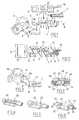
- FIG. 1is an exploded perspective view of a measuring device according to one embodiment
- FIG. 2is a section view on line II-II of FIG. 1 showing the measuring device once assembled
- FIG. 3is a perspective view of a measuring shunt and of its connections according to another embodiment
- FIGS. 4-6show various steps in making the shunt and its connections according to another embodiment
- FIG. 7is a section view on line VII-VII of FIG. 6 showing the shunt and its connections once assembled.
- a measuring device for measuring a current flowing in a cableincludes a measuring shunt connected in series with the cable and associated with a measuring electronic card connected to a data transmission cable, the measuring shunt including a measuring portion of resistive alloy connected to connection portions made of resistive alloy and integrally formed with the measuring portion.
- the power supply cablehas one end secured to one face of a connection portion of the measuring shunt.
- the measuring shuntcan be made by forming a plate of resistive alloy. Fastening the shunt to the end of the cable may be done in an automated manner.
- connection portion remote from the end of the cableis secured directly to a battery cable terminal by welding, preferably to a conductive tab that is integral with the terminal.
- a measuring devicecomprises a measuring shunt 1 , made from a single piece of resistive alloy, such as manganin, and including a central portion defined by holes 3 for forming a measuring portion 2 of measuring shunt L
- measuring shunt 1has connection portions 4 and 5 , which in this embodiment extend parallel to measuring portion 2 , and are offset therefrom.
- Connection portion 4is secured to an end 6 of a conductive core of a cable 7 used for powering equipment.
- the end 6which is initially in the form of a bundle of conductor wires, is pressed against one face of connection portion 4 and is heated (e.g. by ultrasound) so as to melt the bundle of conductor wires thereby perform autogenous welding, as represented by dashed lines in FIG. 1 .
- Connection portion 5is secured in the same manner (i.e. by autogenous welding) to the face of a support tab 8 , which is made of conductive material, such as brass.
- Support tab 8is made integrally with a battery cable terminal 9 .
- support tab 8extends perpendicularly to axis 10 of battery cable terminal 9 in the vicinity of the base.
- the measuring devicealso includes an electronic card 11 having components 12 which form a measuring circuit.
- Electronic card 11is coupled to measuring shunt 1 by inserting connection pins 13 into holes 3 during assembly and soldering connection pins 13 therein in order to measure a potential difference across the ends of measuring portion 2 of measuring shunt 1 .
- Electronic card 11is also coupled to a data transmission cable 14 .
- a block of resin 15is molded around the measuring device so as to finish off the mechanical connection between cable 7 and support tab 8 of battery cable terminal 9 in such a manner that the measuring device is cantilevered out from battery cable terminal 9 . It should be observed that given the disposition of the various components making up the measuring device, the total thickness of resin block 15 is less than that of battery cable terminal 9 .
- measuring shunt 16is in the form of a bent plate having a connection portion 17 with a face on which an end 6 of a conductive core of a cable 7 is secured, while a connection portion 18 remote from end 6 of cable 7 is secured to a connection tab 19 extending parallel to the axis of a battery cable terminal 39 .
- measuring shunt 16has studs 20 that extend from the top edge of measuring shunt 16 to define a measuring portion 21 .
- an electronic card(not shown) is preferably mounted perpendicular to measuring shunt 16 , by inserting studs 20 into holes in an electrical circuit carried by an electronic card.
- the measuring shuntis in the form of a rectangular plane plate 22 .
- the cableis stripped over a length that is slightly greater than the length of rectangular plate 22 so as to reveal its conductive core 23 which is pressed against one of the faces of rectangular plate 22 and autogenously welded thereto by melting the conductor wires making up conductive core 23 .
- conductive core 23is thus in the form of a bar secured to the corresponding face of rectangular plate 22 as shown in FIG. 5 .
- conductive core 23is then machined (e.g.
- the measuring shuntis secured to the ends of two cable segments 24 with their conducive ends 25 being spaced apart by a distance D that defines the measuring portion of measuring shunt.
- an electronic card 26 having circuit contacts 27 on its bottom faceis secured to conductive ends 25 of cable segments 24 in order to pick up a potential difference between conducive ends 25 .
- electronic card 26is connected to a data transmission cable 28 and the assembly is embedded in a resin block 29 .
- the inventionis not restricted to the embodiments shown of the measuring shunt in which one of the connection portions is suitable for securing directly to the side wall or to the end edge of a battery cable terminal of conventional structure.
Landscapes
- Physics & Mathematics (AREA)
- General Physics & Mathematics (AREA)
- Measuring Instrument Details And Bridges, And Automatic Balancing Devices (AREA)
- Connection Of Batteries Or Terminals (AREA)
- Secondary Cells (AREA)
- Arrangements For Transmission Of Measured Signals (AREA)
- Testing Relating To Insulation (AREA)
Abstract
Description
Claims (4)
Priority Applications (2)
| Application Number | Priority Date | Filing Date | Title |
|---|---|---|---|
| US12/423,470US8142237B2 (en) | 2004-12-20 | 2009-04-14 | Device for measuring a current flowing in a cable |
| US12/953,373US8242772B2 (en) | 2004-12-20 | 2010-11-23 | Device for measuring a current flowing in a cable |
Applications Claiming Priority (5)
| Application Number | Priority Date | Filing Date | Title |
|---|---|---|---|
| FR0413593 | 2004-12-20 | ||
| FR0413593AFR2879751B1 (en) | 2004-12-20 | 2004-12-20 | DEVICE FOR MEASURING CIRCULATING CURRENT IN A CABLE |
| US79344005A | 2005-12-13 | 2005-12-13 | |
| PCT/FR2005/003113WO2006067300A1 (en) | 2004-12-20 | 2005-12-13 | Device for measuring a current flowing in a cable |
| US12/423,470US8142237B2 (en) | 2004-12-20 | 2009-04-14 | Device for measuring a current flowing in a cable |
Related Parent Applications (2)
| Application Number | Title | Priority Date | Filing Date |
|---|---|---|---|
| US79344005AContinuation | 2004-12-20 | 2005-12-13 | |
| PCT/FR2005/003113ContinuationWO2006067300A1 (en) | 2004-12-20 | 2005-12-13 | Device for measuring a current flowing in a cable |
Related Child Applications (1)
| Application Number | Title | Priority Date | Filing Date |
|---|---|---|---|
| US12/953,373DivisionUS8242772B2 (en) | 2004-12-20 | 2010-11-23 | Device for measuring a current flowing in a cable |
Publications (2)
| Publication Number | Publication Date |
|---|---|
| US20100066351A1 US20100066351A1 (en) | 2010-03-18 |
| US8142237B2true US8142237B2 (en) | 2012-03-27 |
Family
ID=34952336
Family Applications (2)
| Application Number | Title | Priority Date | Filing Date |
|---|---|---|---|
| US12/423,470ActiveUS8142237B2 (en) | 2004-12-20 | 2009-04-14 | Device for measuring a current flowing in a cable |
| US12/953,373ActiveUS8242772B2 (en) | 2004-12-20 | 2010-11-23 | Device for measuring a current flowing in a cable |
Family Applications After (1)
| Application Number | Title | Priority Date | Filing Date |
|---|---|---|---|
| US12/953,373ActiveUS8242772B2 (en) | 2004-12-20 | 2010-11-23 | Device for measuring a current flowing in a cable |
Country Status (7)
| Country | Link |
|---|---|
| US (2) | US8142237B2 (en) |
| EP (1) | EP1828786B1 (en) |
| JP (2) | JP4769819B2 (en) |
| AT (1) | ATE436025T1 (en) |
| DE (1) | DE602005015357D1 (en) |
| FR (1) | FR2879751B1 (en) |
| WO (1) | WO2006067300A1 (en) |
Cited By (14)
| Publication number | Priority date | Publication date | Assignee | Title |
|---|---|---|---|---|
| US20100316901A1 (en)* | 2009-06-10 | 2010-12-16 | Yazaki Corporation | Battery terminal with current sensor |
| US20110050260A1 (en)* | 2009-08-31 | 2011-03-03 | Denso Corporation | Electric current measuring device with improved installability |
| US20110187346A1 (en)* | 2010-01-29 | 2011-08-04 | Denso Corporation | Current detecting device |
| US20120270452A1 (en)* | 2009-07-02 | 2012-10-25 | Alain Thimon | Battery terminal lug equipped with a shunt for measuring the battery current |
| US20130303030A1 (en)* | 2012-04-24 | 2013-11-14 | Arteche Lantegi Elkartea, S.A. | High-voltage connector |
| US20140134896A1 (en)* | 2012-11-15 | 2014-05-15 | Chang Hwan Precision Terminal Co., Ltd. | Connecting terminal for storage battery |
| USD777055S1 (en) | 2014-04-19 | 2017-01-24 | Mark Taylor | Battery monitoring clamp |
| USD777669S1 (en) | 2014-04-19 | 2017-01-31 | Mark Taylor | Battery monitoring clip |
| US10158204B2 (en)* | 2016-12-09 | 2018-12-18 | Yazaki Corporation | Fixing structure of conductor unit |
| RU2730412C2 (en)* | 2016-05-04 | 2020-08-21 | Сафран Электрикал Энд Пауэр | Electric bus current sensor unit |
| US10770914B2 (en) | 2018-11-05 | 2020-09-08 | C.E. Niehoff & Co. | Dual control loop for charging of batteries |
| US11081814B2 (en)* | 2016-10-31 | 2021-08-03 | Autonetworks Technologies, Ltd. | Wiring module |
| US20230100174A1 (en)* | 2020-03-10 | 2023-03-30 | Koa Corporation | Current sensing device |
| US11811248B2 (en) | 2016-07-21 | 2023-11-07 | C.E. Niehoff & Co. | Vehicle generator using battery charging profiles |
Families Citing this family (46)
| Publication number | Priority date | Publication date | Assignee | Title |
|---|---|---|---|---|
| FR2879751B1 (en)* | 2004-12-20 | 2007-02-23 | Johnson Controls Tech Co | DEVICE FOR MEASURING CIRCULATING CURRENT IN A CABLE |
| DE102005039587A1 (en)* | 2005-08-19 | 2007-02-22 | Robert Bosch Gmbh | Battery sensor unit |
| DE102007006050B8 (en)* | 2006-02-04 | 2013-04-04 | Kromberg & Schubert Kg | connecting device |
| DE102006036247A1 (en)* | 2006-02-16 | 2007-08-23 | Kromberg & Schubert Gmbh & Co. Kg | Terminal device e.g. for current measurement of motor vehicle battery, has pin-shaped section for positioning in battery terminal recess |
| US7688022B2 (en) | 2006-02-17 | 2010-03-30 | Lear Corporation | Energy management system for a vehicle |
| DE102006019911A1 (en)* | 2006-04-28 | 2007-11-08 | Siemens Ag | Shunt for use in battery sensor, has two contact elements attached to sides of resistor element, where one contact element has larger total cross-section area in level running parallel to one side via hole and is thicker towards hole |
| DE102006050573B4 (en)* | 2006-10-26 | 2017-03-09 | Audi Ag | Electrical safety device for battery-connected electrical consumers of a vehicle |
| FR2910719B1 (en)* | 2006-12-26 | 2010-09-10 | Valeo Electronique Sys Liaison | DEVICE FOR CONNECTING AND MEASURING BETWEEN A BATTERY TERMINAL AND AN ELECTRICAL BONDING CABLE. |
| DE102007009569B4 (en)* | 2007-02-27 | 2011-06-16 | Kromberg & Schubert Gmbh & Co. Kg | Connection device and method for its production |
| DE102007018669B8 (en)* | 2007-04-18 | 2014-03-27 | Auto-Kabel Management Gmbh | Batteriepolmessklemme with protective element and method for producing a Batteriepolmessklemme |
| US8476864B2 (en) | 2007-06-13 | 2013-07-02 | Lear Corporation | Battery monitoring system |
| US7663376B2 (en) | 2007-08-06 | 2010-02-16 | Lear Corporation | Printed circuit board for sensing voltage drop |
| JP4897964B2 (en)* | 2007-09-10 | 2012-03-14 | 古河電気工業株式会社 | Current detector |
| DE102008003338A1 (en)* | 2008-01-07 | 2009-07-09 | Robert Bosch Gmbh | Electric current determining device for use in cable i.e. earth cable, has cable provided with cable insulation, where cable insulation is formed such that cable insulation partially encloses measuring element and/or electronic system |
| DE102008003458A1 (en)* | 2008-01-08 | 2009-07-09 | Robert Bosch Gmbh | Electric current determining device for energy storage i.e. battery, of motor vehicle, has sensor resistor electrical conductively connected with cable through contact surface that is oriented parallel to cable longitudinal direction |
| DE102008006866A1 (en)* | 2008-01-31 | 2009-08-06 | Hella Kgaa Hueck & Co. | Device for current measurement |
| DE102008013408A1 (en)* | 2008-03-10 | 2009-09-17 | Robert Bosch Gmbh | Shunt resistor with measuring circuit |
| JP5117248B2 (en)* | 2008-03-31 | 2013-01-16 | 古河電気工業株式会社 | Shunt resistor and terminal mounting method to shunt resistor |
| DE102008002308A1 (en)* | 2008-06-09 | 2009-12-10 | Robert Bosch Gmbh | Pole terminal arrangement for connecting load circuit to motor vehicle battery, has sheet metals enclosed outside by connecting terminal and connection taps projecting from sheet metals to contact measuring lines |
| DE202009010319U1 (en) | 2009-07-01 | 2009-11-19 | Isabellenhütte Heusler Gmbh & Co. Kg | Electronic component |
| DE102010028381A1 (en)* | 2010-04-29 | 2011-11-03 | Robert Bosch Gmbh | Electronic device with press-fit connection |
| JP5723139B2 (en) | 2010-04-30 | 2015-05-27 | 矢崎総業株式会社 | Battery terminal unit with current sensor |
| JP5938778B2 (en)* | 2010-11-17 | 2016-06-22 | 矢崎総業株式会社 | Battery terminal with current sensor |
| KR101517708B1 (en) | 2010-11-17 | 2015-05-04 | 야자키 소교 가부시키가이샤 | Battery terminal with current sensor |
| JP5809793B2 (en)* | 2010-11-17 | 2015-11-11 | 矢崎総業株式会社 | Battery terminal with current sensor |
| DE202011000271U1 (en)* | 2011-02-07 | 2011-03-31 | Bremi Fahrzeug-Elektrik Gmbh + Co. Kg (Bfe) | battery terminal |
| JP5926495B2 (en)* | 2011-04-05 | 2016-05-25 | 矢崎総業株式会社 | Shunt resistance type current sensor |
| WO2013014240A1 (en)* | 2011-07-28 | 2013-01-31 | Continental Teves Ag & Co. Ohg | Circuit for conducting an electric current |
| FR2979707B1 (en)* | 2011-09-07 | 2014-04-25 | Sagemcom Energy & Telecom Sas | MEASURING DEVICE COMPRISING A SHUNT AND AN ELECTRIC COUNTER COMPRISING SUCH A MEASURING DEVICE |
| JP5845057B2 (en)* | 2011-10-31 | 2016-01-20 | 株式会社デンソー | Current detector |
| DE102012007870A1 (en)* | 2012-02-26 | 2013-08-29 | Kromberg & Schubert Kg | Connection of a first metallic component with a coated second metallic component |
| DE102012203446A1 (en)* | 2012-03-05 | 2013-09-05 | Robert Bosch Gmbh | Electronic battery sensor |
| DE102013210128A1 (en)* | 2013-03-05 | 2014-09-11 | Continental Automotive Gmbh | Integrally formed current sensor device |
| DE102013010166A1 (en)* | 2013-06-19 | 2015-01-08 | Auto-Kabel Management Gmbh | Polish integrated starting current limiter |
| JP6234716B2 (en)* | 2013-06-28 | 2017-11-22 | 三洋電機株式会社 | On-vehicle power supply device, vehicle including power supply device, and bus bar |
| DE102014207759A1 (en)* | 2013-07-03 | 2015-01-08 | Continental Automotive Gmbh | Current sensor shunt with holes for press-fit pins |
| CN108054456A (en)* | 2013-07-03 | 2018-05-18 | 古河电气工业株式会社 | Battery condition detection apparatus |
| JP2015021815A (en)* | 2013-07-18 | 2015-02-02 | 矢崎総業株式会社 | Shunt resistance type current sensor |
| JP2015025694A (en)* | 2013-07-25 | 2015-02-05 | 矢崎総業株式会社 | Shunt resistor current sensor |
| WO2015154807A1 (en)* | 2014-04-10 | 2015-10-15 | Kromberg & Schubert Gmbh | Metal component, and method for producing a metal component |
| DE102014011593B4 (en) | 2014-08-01 | 2016-05-04 | Isabellenhütte Heusler Gmbh & Co. Kg | Resistance, in particular low-impedance current measuring resistor |
| DE102015216789A1 (en)* | 2015-09-02 | 2017-03-02 | Continental Automotive Gmbh | Connecting device for connecting a measuring device to a terminal pole of an energy storage device of a motor vehicle |
| JP6400051B2 (en)* | 2016-07-12 | 2018-10-03 | Koa株式会社 | Shunt resistance type current detector |
| JP2019165057A (en)* | 2018-03-19 | 2019-09-26 | サンコール株式会社 | Shunt resistor and method of manufacturing the same |
| EP3640650B1 (en)* | 2018-10-15 | 2021-06-02 | Continental Automotive GmbH | Method for manufacturing a resistor unit for a battery sensor and resistor unit |
| DE102020007556A1 (en) | 2020-12-10 | 2022-06-15 | Wieland-Werke Aktiengesellschaft | Resistor arrangement and method for its manufacture |
Citations (43)
| Publication number | Priority date | Publication date | Assignee | Title |
|---|---|---|---|---|
| US3166650A (en)* | 1961-11-20 | 1965-01-19 | Sun Electric Corp | Switch adapter and connector for automobile electrical system testers |
| US4572878A (en)* | 1984-12-19 | 1986-02-25 | General Motors Corporation | Battery temperature sensor and housing therefor |
| US4584525A (en) | 1983-04-18 | 1986-04-22 | General Electric Company | Current-shunt system for known conductors |
| US4629979A (en) | 1983-08-31 | 1986-12-16 | Hydro-Quebec | Apparatus for sensing and measuring a current on power transmission line |
| US4661807A (en)* | 1984-10-12 | 1987-04-28 | Gould Inc. | Electric fuse holder having an integral current sensor |
| US4675255A (en)* | 1985-09-09 | 1987-06-23 | Vdo Adolf Schindling Ag | Battery pole terminal with current sensor |
| US5027059A (en) | 1989-08-24 | 1991-06-25 | Schlumberger Industries, Inc. | Differential current shunt |
| US5214407A (en) | 1991-11-06 | 1993-05-25 | Hewlett-Packard Company | High performance current shunt |
| US5877563A (en)* | 1995-02-06 | 1999-03-02 | Bayerische Motoren Werke Aktiengellschaft | Fuse device for a cable in motor vehicles |
| US6218805B1 (en) | 1998-04-17 | 2001-04-17 | Menico Ag | Measuring battery clamps |
| EP1107009A1 (en) | 1999-12-09 | 2001-06-13 | Sagem Sa | Current intensity measuring apparatus in a conductor |
| DE10000500A1 (en) | 2000-01-08 | 2001-07-26 | Bosch Gmbh Robert | Current measurement device for electronics module, has manganin strip which is welded directly to the seams of sense conductors of current feed and shunt units |
| US6304062B1 (en) | 1999-10-28 | 2001-10-16 | Powersmart, Inc. | Shunt resistance device for monitoring battery state of charge |
| US6347958B1 (en)* | 2000-09-18 | 2002-02-19 | Real Power Cap Company | Connecting device to vehicle battery terminals |
| US6515468B1 (en)* | 1999-08-27 | 2003-02-04 | Yazaki Corporation | Current sensor and electric circuit using the same |
| US6544078B2 (en)* | 2001-07-18 | 2003-04-08 | Midtronics, Inc. | Battery clamp with integrated current sensor |
| US6551147B2 (en)* | 2000-11-01 | 2003-04-22 | Sumitomo Wiring Systems, Ltd. | Battery terminal provided with a current sensor |
| US6719595B1 (en)* | 1998-08-01 | 2004-04-13 | Bernhard Fröhlich | Battery terminal connection cable |
| US20040155645A1 (en) | 2003-02-10 | 2004-08-12 | Siemens Vdo Automotive Inc. | Jump bar shunt structure for power components |
| US6787935B2 (en) | 1999-12-18 | 2004-09-07 | Bayerische Motoren Werke Aktiengesellschaft | Battery sensor device |
| US6791315B2 (en)* | 2000-01-06 | 2004-09-14 | Delta Electrical Limited | Current detector and current measuring apparatus including such detector with temperature compensation |
| US6793534B2 (en)* | 2003-02-21 | 2004-09-21 | Wen Tsung Cheng | Power distribution outlet with fuse |
| US6808841B2 (en)* | 2000-11-01 | 2004-10-26 | Sumitomo Wiring Systems, Ltd. | Battery terminal unit provided with a current sensor |
| US6856162B1 (en)* | 2004-02-12 | 2005-02-15 | Vena Engineering Corp | AC/DC monitor system |
| US7198510B2 (en)* | 2001-11-14 | 2007-04-03 | Midtronics, Inc. | Kelvin connector for a battery post |
| US7233474B2 (en)* | 2003-11-26 | 2007-06-19 | Littelfuse, Inc. | Vehicle electrical protection device and system employing same |
| US7319304B2 (en)* | 2003-07-25 | 2008-01-15 | Midtronics, Inc. | Shunt connection to a PCB of an energy management system employed in an automotive vehicle |
| US7344420B2 (en)* | 2004-09-14 | 2008-03-18 | Denso Corporation | Current sensor and mounting structure thereof |
| US7381101B2 (en)* | 2006-08-25 | 2008-06-03 | Lear Corporation | Battery post connector |
| US7385828B2 (en)* | 2006-01-27 | 2008-06-10 | Delphi Technologies, Inc. | Electronic shunt resistor assembly |
| US7405570B2 (en)* | 2004-02-09 | 2008-07-29 | Siemens Aktiengesellschaft | Connector for a measurement element in a battery sensor |
| US7456616B2 (en)* | 2005-08-04 | 2008-11-25 | Remy Technologies, L.L.C. | Current sensor for electric machine control |
| US7491097B2 (en)* | 2005-03-02 | 2009-02-17 | Denso Corporation | Mounting structure of current sensor |
| US7500888B2 (en)* | 2007-02-08 | 2009-03-10 | Lear Corporation | Battery post connector |
| US20090195252A1 (en)* | 2006-06-26 | 2009-08-06 | Sergej Kerbel | Battery Sensor Unit and Method for Manufacturing the Battery Sensor Unit |
| US7573274B2 (en)* | 2006-08-04 | 2009-08-11 | Denso Corporation | Current sensor |
| US7578710B2 (en)* | 2006-08-12 | 2009-08-25 | Robert Bosch Gmbh | Electrical device |
| US20100019733A1 (en)* | 2008-07-23 | 2010-01-28 | Lear Corporation | Battery monitoring system |
| US7663376B2 (en)* | 2007-08-06 | 2010-02-16 | Lear Corporation | Printed circuit board for sensing voltage drop |
| US7671755B2 (en)* | 2004-11-03 | 2010-03-02 | Leopold Kostal Gmbh & Co. Kg | Battery current sensor for a motor vehicle |
| US7755346B2 (en)* | 2005-08-01 | 2010-07-13 | Denso Corporation | Mounting structure for current sensor |
| US20110062945A1 (en)* | 2004-12-20 | 2011-03-17 | Johnson Controls Technology Company | Device for measuring a current flowing in a cable |
| US20110076888A1 (en)* | 2007-06-04 | 2011-03-31 | Lear Corporation | Battery post connector |
Family Cites Families (10)
| Publication number | Priority date | Publication date | Assignee | Title |
|---|---|---|---|---|
| FR2470972A1 (en)* | 1979-11-28 | 1981-06-12 | Enertec | CURRENT-TO-VOLTAGE CONVERTER, PARTICULARLY FOR ELECTRICAL ENERGY MEASUREMENT CIRCUIT |
| JPH0483175A (en)* | 1990-07-25 | 1992-03-17 | Mitsubishi Electric Corp | current detection device |
| ES2130637T3 (en) | 1994-09-12 | 1999-07-01 | Hottinger Maschb Gmbh | DEVICE FOR THE INSERTION OF A PIECE IN A CASTING MALE THAT MUST BE COMPLETED IN A STACKING OF NUCLEUS PLATES. |
| GB9813982D0 (en)* | 1998-06-30 | 1998-08-26 | Mem Limited | Residual current detection device |
| JP2001272422A (en)* | 2000-03-27 | 2001-10-05 | Jeco Co Ltd | Vehicle current detector |
| JP4149698B2 (en)* | 2001-11-06 | 2008-09-10 | 矢崎総業株式会社 | Current detection device and fusible link unit using the current detection device |
| JP4029049B2 (en)* | 2003-01-10 | 2008-01-09 | 三菱電機株式会社 | Current detection resistor |
| JP4026762B2 (en)* | 2003-01-16 | 2007-12-26 | 矢崎総業株式会社 | Current sensor mounting structure |
| US7945512B2 (en)* | 2007-03-14 | 2011-05-17 | Ebay Inc. | Spending and savings secondary linked accounts |
| US20110089931A1 (en)* | 2009-10-19 | 2011-04-21 | Nemic-Lambda Ltd. | Temperature-compensated shunt current measurement |
- 2004
- 2004-12-20FRFR0413593Apatent/FR2879751B1/ennot_activeExpired - Fee Related
- 2005
- 2005-12-13EPEP05848345Apatent/EP1828786B1/ennot_activeNot-in-force
- 2005-12-13DEDE602005015357Tpatent/DE602005015357D1/enactiveActive
- 2005-12-13ATAT05848345Tpatent/ATE436025T1/ennot_activeIP Right Cessation
- 2005-12-13JPJP2007546108Apatent/JP4769819B2/ennot_activeExpired - Fee Related
- 2005-12-13WOPCT/FR2005/003113patent/WO2006067300A1/enactiveApplication Filing
- 2009
- 2009-04-14USUS12/423,470patent/US8142237B2/enactiveActive
- 2010
- 2010-11-23USUS12/953,373patent/US8242772B2/enactiveActive
- 2011
- 2011-01-25JPJP2011012851Apatent/JP2011123080A/enactivePending
Patent Citations (44)
| Publication number | Priority date | Publication date | Assignee | Title |
|---|---|---|---|---|
| US3166650A (en)* | 1961-11-20 | 1965-01-19 | Sun Electric Corp | Switch adapter and connector for automobile electrical system testers |
| US4584525A (en) | 1983-04-18 | 1986-04-22 | General Electric Company | Current-shunt system for known conductors |
| US4629979A (en) | 1983-08-31 | 1986-12-16 | Hydro-Quebec | Apparatus for sensing and measuring a current on power transmission line |
| US4661807A (en)* | 1984-10-12 | 1987-04-28 | Gould Inc. | Electric fuse holder having an integral current sensor |
| US4572878A (en)* | 1984-12-19 | 1986-02-25 | General Motors Corporation | Battery temperature sensor and housing therefor |
| US4675255A (en)* | 1985-09-09 | 1987-06-23 | Vdo Adolf Schindling Ag | Battery pole terminal with current sensor |
| US5027059A (en) | 1989-08-24 | 1991-06-25 | Schlumberger Industries, Inc. | Differential current shunt |
| US5214407A (en) | 1991-11-06 | 1993-05-25 | Hewlett-Packard Company | High performance current shunt |
| US5877563A (en)* | 1995-02-06 | 1999-03-02 | Bayerische Motoren Werke Aktiengellschaft | Fuse device for a cable in motor vehicles |
| US6218805B1 (en) | 1998-04-17 | 2001-04-17 | Menico Ag | Measuring battery clamps |
| US6719595B1 (en)* | 1998-08-01 | 2004-04-13 | Bernhard Fröhlich | Battery terminal connection cable |
| US6515468B1 (en)* | 1999-08-27 | 2003-02-04 | Yazaki Corporation | Current sensor and electric circuit using the same |
| US6304062B1 (en) | 1999-10-28 | 2001-10-16 | Powersmart, Inc. | Shunt resistance device for monitoring battery state of charge |
| US6522123B2 (en) | 1999-12-09 | 2003-02-18 | Sagem Sa | Apparatus for measuring current flowing in a conductor |
| EP1107009A1 (en) | 1999-12-09 | 2001-06-13 | Sagem Sa | Current intensity measuring apparatus in a conductor |
| US6787935B2 (en) | 1999-12-18 | 2004-09-07 | Bayerische Motoren Werke Aktiengesellschaft | Battery sensor device |
| US6791315B2 (en)* | 2000-01-06 | 2004-09-14 | Delta Electrical Limited | Current detector and current measuring apparatus including such detector with temperature compensation |
| DE10000500A1 (en) | 2000-01-08 | 2001-07-26 | Bosch Gmbh Robert | Current measurement device for electronics module, has manganin strip which is welded directly to the seams of sense conductors of current feed and shunt units |
| US6347958B1 (en)* | 2000-09-18 | 2002-02-19 | Real Power Cap Company | Connecting device to vehicle battery terminals |
| US6551147B2 (en)* | 2000-11-01 | 2003-04-22 | Sumitomo Wiring Systems, Ltd. | Battery terminal provided with a current sensor |
| US6808841B2 (en)* | 2000-11-01 | 2004-10-26 | Sumitomo Wiring Systems, Ltd. | Battery terminal unit provided with a current sensor |
| US6544078B2 (en)* | 2001-07-18 | 2003-04-08 | Midtronics, Inc. | Battery clamp with integrated current sensor |
| US7198510B2 (en)* | 2001-11-14 | 2007-04-03 | Midtronics, Inc. | Kelvin connector for a battery post |
| US20040155645A1 (en) | 2003-02-10 | 2004-08-12 | Siemens Vdo Automotive Inc. | Jump bar shunt structure for power components |
| US6793534B2 (en)* | 2003-02-21 | 2004-09-21 | Wen Tsung Cheng | Power distribution outlet with fuse |
| US7319304B2 (en)* | 2003-07-25 | 2008-01-15 | Midtronics, Inc. | Shunt connection to a PCB of an energy management system employed in an automotive vehicle |
| US7233474B2 (en)* | 2003-11-26 | 2007-06-19 | Littelfuse, Inc. | Vehicle electrical protection device and system employing same |
| US7405570B2 (en)* | 2004-02-09 | 2008-07-29 | Siemens Aktiengesellschaft | Connector for a measurement element in a battery sensor |
| US6856162B1 (en)* | 2004-02-12 | 2005-02-15 | Vena Engineering Corp | AC/DC monitor system |
| US7344420B2 (en)* | 2004-09-14 | 2008-03-18 | Denso Corporation | Current sensor and mounting structure thereof |
| US7671755B2 (en)* | 2004-11-03 | 2010-03-02 | Leopold Kostal Gmbh & Co. Kg | Battery current sensor for a motor vehicle |
| US20110062945A1 (en)* | 2004-12-20 | 2011-03-17 | Johnson Controls Technology Company | Device for measuring a current flowing in a cable |
| US7491097B2 (en)* | 2005-03-02 | 2009-02-17 | Denso Corporation | Mounting structure of current sensor |
| US7755346B2 (en)* | 2005-08-01 | 2010-07-13 | Denso Corporation | Mounting structure for current sensor |
| US7456616B2 (en)* | 2005-08-04 | 2008-11-25 | Remy Technologies, L.L.C. | Current sensor for electric machine control |
| US7385828B2 (en)* | 2006-01-27 | 2008-06-10 | Delphi Technologies, Inc. | Electronic shunt resistor assembly |
| US20090195252A1 (en)* | 2006-06-26 | 2009-08-06 | Sergej Kerbel | Battery Sensor Unit and Method for Manufacturing the Battery Sensor Unit |
| US7573274B2 (en)* | 2006-08-04 | 2009-08-11 | Denso Corporation | Current sensor |
| US7578710B2 (en)* | 2006-08-12 | 2009-08-25 | Robert Bosch Gmbh | Electrical device |
| US7381101B2 (en)* | 2006-08-25 | 2008-06-03 | Lear Corporation | Battery post connector |
| US7500888B2 (en)* | 2007-02-08 | 2009-03-10 | Lear Corporation | Battery post connector |
| US20110076888A1 (en)* | 2007-06-04 | 2011-03-31 | Lear Corporation | Battery post connector |
| US7663376B2 (en)* | 2007-08-06 | 2010-02-16 | Lear Corporation | Printed circuit board for sensing voltage drop |
| US20100019733A1 (en)* | 2008-07-23 | 2010-01-28 | Lear Corporation | Battery monitoring system |
Non-Patent Citations (3)
| Title |
|---|
| International Search Report for PCT/FR2005/003113 dated Apr. 7, 2006, 3 pages. |
| US Office Action received in U.S. Appl. No. 12/953,373, dated Mar. 10, 2011. |
| Written Opinion of the International Searching Authority for PCT/FR2005/003113 dated Apr. 19, 2006, 5 pages. |
Cited By (22)
| Publication number | Priority date | Publication date | Assignee | Title |
|---|---|---|---|---|
| US20100316901A1 (en)* | 2009-06-10 | 2010-12-16 | Yazaki Corporation | Battery terminal with current sensor |
| US8709627B2 (en)* | 2009-06-10 | 2014-04-29 | Yazaki Corporation | Battery terminal with current sensor |
| US20120270452A1 (en)* | 2009-07-02 | 2012-10-25 | Alain Thimon | Battery terminal lug equipped with a shunt for measuring the battery current |
| US8932086B2 (en)* | 2009-07-02 | 2015-01-13 | Valeo Equipements Electriques Moteur | Battery terminal lug equipped with shunt for measuring battery current |
| US20110050260A1 (en)* | 2009-08-31 | 2011-03-03 | Denso Corporation | Electric current measuring device with improved installability |
| US8680878B2 (en)* | 2009-08-31 | 2014-03-25 | Denso Corporation | Electric current measuring device with improved installability |
| US20110187346A1 (en)* | 2010-01-29 | 2011-08-04 | Denso Corporation | Current detecting device |
| US8624600B2 (en)* | 2010-01-29 | 2014-01-07 | Denso Corporation | Current detecting device |
| US20130303030A1 (en)* | 2012-04-24 | 2013-11-14 | Arteche Lantegi Elkartea, S.A. | High-voltage connector |
| US9209575B2 (en)* | 2012-04-24 | 2015-12-08 | Arteche Lantegi Elkartea, S.A. | High-voltage connector |
| US9022815B2 (en)* | 2012-11-15 | 2015-05-05 | Chang Hwan Precision Terminal Co., Ltd. | Connecting terminal for storage battery |
| US20140134896A1 (en)* | 2012-11-15 | 2014-05-15 | Chang Hwan Precision Terminal Co., Ltd. | Connecting terminal for storage battery |
| USD777055S1 (en) | 2014-04-19 | 2017-01-24 | Mark Taylor | Battery monitoring clamp |
| USD777669S1 (en) | 2014-04-19 | 2017-01-31 | Mark Taylor | Battery monitoring clip |
| RU2730412C2 (en)* | 2016-05-04 | 2020-08-21 | Сафран Электрикал Энд Пауэр | Electric bus current sensor unit |
| US10782322B2 (en) | 2016-05-04 | 2020-09-22 | Safran Electrical & Power | Busbar current sensor assembly |
| US11811248B2 (en) | 2016-07-21 | 2023-11-07 | C.E. Niehoff & Co. | Vehicle generator using battery charging profiles |
| US11081814B2 (en)* | 2016-10-31 | 2021-08-03 | Autonetworks Technologies, Ltd. | Wiring module |
| US10158204B2 (en)* | 2016-12-09 | 2018-12-18 | Yazaki Corporation | Fixing structure of conductor unit |
| US10770914B2 (en) | 2018-11-05 | 2020-09-08 | C.E. Niehoff & Co. | Dual control loop for charging of batteries |
| US20230100174A1 (en)* | 2020-03-10 | 2023-03-30 | Koa Corporation | Current sensing device |
| US12241914B2 (en)* | 2020-03-10 | 2025-03-04 | Koa Corporation | Current sensing device |
Also Published As
| Publication number | Publication date |
|---|---|
| JP2008524568A (en) | 2008-07-10 |
| ATE436025T1 (en) | 2009-07-15 |
| FR2879751B1 (en) | 2007-02-23 |
| US20110062945A1 (en) | 2011-03-17 |
| EP1828786A1 (en) | 2007-09-05 |
| EP1828786B1 (en) | 2009-07-08 |
| WO2006067300A1 (en) | 2006-06-29 |
| US20100066351A1 (en) | 2010-03-18 |
| JP4769819B2 (en) | 2011-09-07 |
| JP2011123080A (en) | 2011-06-23 |
| DE602005015357D1 (en) | 2009-08-20 |
| US8242772B2 (en) | 2012-08-14 |
| FR2879751A1 (en) | 2006-06-23 |
Similar Documents
| Publication | Publication Date | Title |
|---|---|---|
| US8142237B2 (en) | Device for measuring a current flowing in a cable | |
| US7578710B2 (en) | Electrical device | |
| EP0411613B1 (en) | A molded circuit component unit for connecting lead wires and a method of manufacturing same | |
| EP3748369A1 (en) | Hybrid current measurement device | |
| US11293952B2 (en) | Passive current sensor with simplified geometry | |
| US6027381A (en) | Insert molded compression connector | |
| US6359770B1 (en) | Power distribution circuit board with bullet connectors | |
| CN113966540B (en) | Shunt resistor module | |
| CA2264335A1 (en) | Hermetic terminal with conductor pin identifier | |
| CN108054456A (en) | Battery condition detection apparatus | |
| CN110568242A (en) | current sensor | |
| US7094073B2 (en) | Relay connection circuit and relay connector | |
| US20170222282A1 (en) | Battery diagnostic sensor unit | |
| US7414194B2 (en) | Bus bar wiring board and method of assembling the same | |
| JPH0935542A (en) | Improved flexible strip cable | |
| US8313341B1 (en) | Guide element for a connector device | |
| JP2001035343A (en) | Earth leakage breaker | |
| JP3330452B2 (en) | Current transformer | |
| JPH04132180A (en) | connector | |
| KR100802505B1 (en) | PCB Package for Mobile Terminal | |
| CN212694978U (en) | Connection structure of current transformer | |
| JP2000209744A (en) | Electric circuit material and electrical connection box provided with the same | |
| JP2000209742A (en) | Electric circuit material and electrical junction box provided with the same | |
| JP2024007201A (en) | current sensor | |
| JP2996163B2 (en) | Electrical junction box for mounting small integrated fuses |
Legal Events
| Date | Code | Title | Description |
|---|---|---|---|
| AS | Assignment | Owner name:JOHNSON CONTROLS TECHNOLOGY COMPANY,MICHIGAN Free format text:ASSIGNMENT OF ASSIGNORS INTEREST;ASSIGNORS:CONDAMIN, BRUNO;MUIS, PASCAL;BAGES, GHISLAIN;SIGNING DATES FROM 20090630 TO 20091116;REEL/FRAME:023577/0569 Owner name:KROMBERG & SCHUBERT GMBH & CO. KG,GERMANY Free format text:ASSIGNMENT OF ASSIGNORS INTEREST;ASSIGNORS:CONDAMIN, BRUNO;MUIS, PASCAL;BAGES, GHISLAIN;SIGNING DATES FROM 20090630 TO 20091116;REEL/FRAME:023577/0569 Owner name:KROMBERG & SCHUBERT GMBH & CO. KG, GERMANY Free format text:ASSIGNMENT OF ASSIGNORS INTEREST;ASSIGNORS:CONDAMIN, BRUNO;MUIS, PASCAL;BAGES, GHISLAIN;SIGNING DATES FROM 20090630 TO 20091116;REEL/FRAME:023577/0569 Owner name:JOHNSON CONTROLS TECHNOLOGY COMPANY, MICHIGAN Free format text:ASSIGNMENT OF ASSIGNORS INTEREST;ASSIGNORS:CONDAMIN, BRUNO;MUIS, PASCAL;BAGES, GHISLAIN;SIGNING DATES FROM 20090630 TO 20091116;REEL/FRAME:023577/0569 | |
| STCF | Information on status: patent grant | Free format text:PATENTED CASE | |
| FEPP | Fee payment procedure | Free format text:PAYOR NUMBER ASSIGNED (ORIGINAL EVENT CODE: ASPN); ENTITY STATUS OF PATENT OWNER: LARGE ENTITY | |
| REMI | Maintenance fee reminder mailed | ||
| FPAY | Fee payment | Year of fee payment:4 | |
| SULP | Surcharge for late payment | ||
| AS | Assignment | Owner name:CPS TECHNOLOGY HOLDINGS, LLC, NEW YORK Free format text:ASSIGNMENT OF ASSIGNORS INTEREST;ASSIGNOR:JOHNSON CONTROLS TECHNOLOGY COMPANY;REEL/FRAME:049610/0807 Effective date:20190430 | |
| AS | Assignment | Owner name:CITIBANK N.A., AS COLLATERAL AGENT, NEW YORK Free format text:ABL PATENT SECURITY AGREEMENT;ASSIGNOR:CPS TECHNOLOGY HOLDINGS LLC;REEL/FRAME:050229/0079 Effective date:20190827 Owner name:CITIBANK N.A., AS COLLATERAL AGENT, DELAWARE Free format text:FIRST LIEN PATENT SECURITY AGREEMENT;ASSIGNOR:CPS TECHNOLOGY HOLDINGS LLC;REEL/FRAME:050229/0029 Effective date:20190827 | |
| MAFP | Maintenance fee payment | Free format text:PAYMENT OF MAINTENANCE FEE, 8TH YEAR, LARGE ENTITY (ORIGINAL EVENT CODE: M1552); ENTITY STATUS OF PATENT OWNER: LARGE ENTITY Year of fee payment:8 | |
| MAFP | Maintenance fee payment | Free format text:PAYMENT OF MAINTENANCE FEE, 12TH YEAR, LARGE ENTITY (ORIGINAL EVENT CODE: M1553); ENTITY STATUS OF PATENT OWNER: LARGE ENTITY Year of fee payment:12 |