US8142145B2 - Riser clamp for pumps for pumping molten metal - Google Patents
Riser clamp for pumps for pumping molten metalDownload PDFInfo
- Publication number
- US8142145B2 US8142145B2US12/427,330US42733009AUS8142145B2US 8142145 B2US8142145 B2US 8142145B2US 42733009 AUS42733009 AUS 42733009AUS 8142145 B2US8142145 B2US 8142145B2
- Authority
- US
- United States
- Prior art keywords
- clamp
- riser
- socket
- molten metal
- base
- Prior art date
- Legal status (The legal status is an assumption and is not a legal conclusion. Google has not performed a legal analysis and makes no representation as to the accuracy of the status listed.)
- Expired - Fee Related, expires
Links
- 239000002184metalSubstances0.000titleclaimsabstractdescription35
- 238000005086pumpingMethods0.000titleclaimsabstractdescription6
- 239000011819refractory materialSubstances0.000claimsabstractdescription10
- 238000004891communicationMethods0.000claimsdescription3
- 239000012530fluidSubstances0.000claimsdescription3
- 239000004568cementSubstances0.000description3
- 230000004907fluxEffects0.000description2
- 238000003466weldingMethods0.000description2
- 238000002347injectionMethods0.000description1
- 239000007924injectionSubstances0.000description1
- 238000009434installationMethods0.000description1
- 238000012986modificationMethods0.000description1
- 230000004048modificationEffects0.000description1
Images


Classifications
- F—MECHANICAL ENGINEERING; LIGHTING; HEATING; WEAPONS; BLASTING
- F04—POSITIVE - DISPLACEMENT MACHINES FOR LIQUIDS; PUMPS FOR LIQUIDS OR ELASTIC FLUIDS
- F04D—NON-POSITIVE-DISPLACEMENT PUMPS
- F04D7/00—Pumps adapted for handling specific fluids, e.g. by selection of specific materials for pumps or pump parts
- F04D7/02—Pumps adapted for handling specific fluids, e.g. by selection of specific materials for pumps or pump parts of centrifugal type
- F04D7/06—Pumps adapted for handling specific fluids, e.g. by selection of specific materials for pumps or pump parts of centrifugal type the fluids being hot or corrosive, e.g. liquid metals
- F04D7/065—Pumps adapted for handling specific fluids, e.g. by selection of specific materials for pumps or pump parts of centrifugal type the fluids being hot or corrosive, e.g. liquid metals for liquid metal
- F—MECHANICAL ENGINEERING; LIGHTING; HEATING; WEAPONS; BLASTING
- F04—POSITIVE - DISPLACEMENT MACHINES FOR LIQUIDS; PUMPS FOR LIQUIDS OR ELASTIC FLUIDS
- F04D—NON-POSITIVE-DISPLACEMENT PUMPS
- F04D29/00—Details, component parts, or accessories
- F04D29/60—Mounting; Assembling; Disassembling
- F04D29/62—Mounting; Assembling; Disassembling of radial or helico-centrifugal pumps
- F04D29/628—Mounting; Assembling; Disassembling of radial or helico-centrifugal pumps especially adapted for liquid pumps
Definitions
- the fieldrelates to transfer pumps for molten metal and, in particular, to a device for securing a riser of the pump to a motor mount.
- Transfer pumpscan be used to transfer molten metal from one location to another, which are referred to as transfer pumps.
- transfer pumpsusually, such pumps only transfer molten metal between locations or only circulate molten metal.
- a new design by the assigneecan combine functions in a single pump. That is, the same pump can transfer the molten metal between locations or circulate the molten metal around the pump, or can conduct both operations simultaneously.
- Transfer pumpsinclude a pump base that is submerged in the molten metal and include a riser enabling the molten metal to travel along a passageway of the riser, to an elbow at the motor mount above the molten metal, and then along the piping there to another location.
- a transfer pump for pumping molten metalhaving a riser with a reusable socket.
- a motorhas a drive shaft.
- Support structureis located above a bath of molten metal on which the motor is disposed.
- a shaft made of refractory materialhas a first end coupled to the drive shaft and a second end.
- An impeller made of refractory materialis connected to the second end of the shaft.
- a base made of refractory materialhas an impeller chamber in which the impeller is rotatably disposed and a transfer opening.
- An inlet openingleads from an exterior surface of the base into the impeller chamber.
- a riser made of refractory materialextends from the transfer opening to the support structure. The riser has a passageway for molten metal along its length.
- a clamphas a first clamp portion fixedly connected to the support structure and a second clamp portion that is pivotable with respect to the first clamp portion, and a fastener for opening and closing the clamp.
- a split sockethas a flange and a body portion. The socket is received in the clamp such that the flange of the socket is disposed above the clamp and when the clamp is closed the socket holds the riser.
- the risercan abut against the base in fluid communication with the transfer opening without being fastened or cemented to the base.
- the support structurecan include a plate on which the motor is mounted and a slot in the plate.
- the first clamp portionis fixedly fastened to the plate in the slot such as by welding.
- the riserincludes a projection or a recess in its exterior surface.
- the split socketcomprises two or more sections. Each of the socket sections includes an interior surface having a projection or a recess such that the projection of the riser or socket corresponds to the recess of the riser or socket.
- a pivotcan be located at one end of the clamp portions and one of the clamp portions can comprise a fork at another end of the clamp portions.
- the fastenerincludes a swing bolt rotatably fastened to a clamp portion and movable into the fork and a nut which is rotatable on the swing bolt against the fork. An obstruction on the swing bolt can prevent the nut from being removed from the swing bolt.
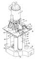
- FIG. 1is a perspective view of a pump for pumping molten metal using a clamp of this disclosure
- FIG. 2is a side view of the pump of FIG. 1 ;
- FIG. 3is an exploded view of the clamp, socket and riser assembly of FIG. 1 ;
- FIG. 4is a cross-sectional view as seen along the lines and arrows 4 - 4 of FIG. 2 ;
- FIG. 5is a cross-sectional view as seen along the lines and arrows 5 - 5 of FIG. 4 .
- a transfer pump 10 for pumping molten metalhas a quickly replaceable riser 12 .
- a motor 14has a drive shaft 16 .
- Support structure referred to as a motor mount 18 a plateis located above a bath of molten metal 20 .
- the motoris disposed on the motor mount.
- a shaft 22has a first end 24 coupled to the drive shaft and a second end 26 on which an impeller 29 is connected as with threads or cement.
- the impellerhas bearing rings 30 as known in the art that engage corresponding bearing rings 32 of the base.
- a base 28has an impeller chamber 34 in which the impeller is rotatably disposed and a transfer opening 36 in fluid communication with the impeller chamber. The transfer opening leads to exterior surface 41 of the base.
- a collar 37may be cemented in the transfer opening to provide a conical mounting surface for the riser.
- Many impellersare known in the art such as vaned and barrel types of impellers. Suitable impellers are disclosed, for example, in U.S. Pub. No. 2006/0198725, which is incorporated herein by reference in its entirety.
- the impeller chambercan be formed with or without a volute but is shown with a volute 38 in FIG. 4 .
- An inlet opening 40leads from the exterior surface 41 of the base into the impeller chamber 34 and an optional discharge passageway 42 leads from the impeller chamber 34 to the exterior surface 41 of the base.
- a transfer-only pump suitable for use with the clamp assembly of this disclosurewould only include a transfer opening and riser without a discharge passageway.
- the pump shown in the drawingsis able to lift the impeller to achieve multiple transfer or discharge functions as described in the 2006/0198725 application.
- the riser 12extends from the transfer opening 36 to the motor mount 18 .
- the riserhas a central passageway 44 along its length for movement of molten metal.
- Support posts 46are cemented to the top of the base and fit into sockets fastened to the motor mount.
- a clamp 48has a first clamp portion 50 mounted to the support structure, such as by welding, and a second clamp portion 52 that is pivotable with respect to the first clamp portion.
- a fastener 54is mounted so as to prevent its removal from the clamp for opening and closing the clamp and permitting and preventing movement of the second clamp portion.
- a split socket 56has a pair of sections 58 , 60 that are disposed above the clamp. Each section of the split socket includes an interior surface 62 that mates with the exterior surface 64 at the top of the riser.
- the socket sectionseach have a circumferential projection 66 that engages a circumferential recess 68 at the top of the riser.
- the pumpcan include a device including a conduit 69 for flux injection into the molten metal as disclosed in published patent application, U.S. Pub. No. 2008/0236336, which is incorporated herein by reference in its entirety. All of the pump components that contact the molten metal are formed of a refractory material including the impeller, shaft, riser, flux conduit, posts and base.
- the motor mounthas a slot 70 .
- the first clamp portion 50is fixedly connected to the motor mount in this slot.
- the second clamp 52is movable about a pivot 72 relative to the first clamp portion.
- At the end of the clamp 74 opposite to the end 76 with the pivotis disposed a swing bolt 78 .
- the swing boltmoves about a pivot point 80 in the first clamp portion.
- a fastener 82(nut) is located on the swing bolt but has a limited travel due to a spot weld 84 on the bolt.
- the second clamp portion 52has projections 86 of a fork 88 that receives the swing bolt. The nut can be tightened in the fork against the projections 86 to firmly close the clamp.
- the riseris an elongated tube that has the central passageway 44 throughout its length.
- the riserhas first and second circumferential surfaces 90 , 92 on either side of the intermediate circumferential surface or recess 68 .
- An upper end portion 94 of the riseris flat while a lower end portion 96 of the riser has a conical surface 98 .
- the conical lower end portion of the riseris sized to be freely received, without fastening or cement, partway into the opening of the collar 37 so that the conical surfaces of the riser and collar engage each other. The riser remains pressed against the base without fasteners or cement while the pump operates.
- the split socketincludes two upper flanges 100 , 102 and two socket body portions 104 , 106 each extending downwardly from one of the flanges.
- Each of the socket body portionshas the interior surface 62 . Configured and arranged on this interior surface is an engagement surface that corresponds to the exterior surface of the riser.
- the engagement surface of the socket bodyincludes first and second circumferential engagement portions 108 , 110 and the intermediate projection 66 extending between them.
- the intermediate projection 66 of each of the socket sectionsfits into the intermediate recess 68 of the riser.
- the first and second engagement portions 108 , 110 of each socket sectioncontact the first and second engagement surfaces 90 , 92 of the riser. This is accomplished by locating the halves of the split socket so that its projections are located relative to the corresponding recess of the riser and then placing the corresponding surfaces in contact with one another.
- the socketWhen the clamp is open the socket is placed inside of it so that the socket flanges are disposed above an upper surface 112 of the clamp. Once the second clamp portion is closed, this applies pressure to the socket halves against the riser, holding the riser tightly in the socket. The swing bolt is then rotated into the fork and the nut is tightened against the protrusions of the fork, securely fastening the riser to the motor mount.
- the pumpis referred to as a transfer pump as is known in the art because it delivers molten metal along the riser for transfer to another location.
- the pumpalso has the ability to circulate molten metal as described in published U.S. patent application U.S. Pub. No. 2006/0198725. That is, the pump is a multifunctional pump that combines transfer and circulation/discharge functions.
- An elbow 114has a flange 116 which is fastened to the flanges 100 , 102 of the split socket.
- Other pipingis connected to another flange 118 of the elbow to direct the molten metal to desired locations.
- the rotating drive shaftrotates the coupled pump shaft.
- the impeller that is connected to the pump shaftrotates in the impeller chamber. This causes molten metal to travel through the pump inlet opening into the impeller chamber of the base. If desired, molten metal also travels from the impeller chamber of the base through the discharge passageway along a discharge stream outside the base. Some of the molten metal (or all of the molten metal in a transfer-only functioning pump) leaves the base through the transfer opening. This molten metal is pumped along the riser, the elbow and piping attached to the elbow to a remote location.
- the riserneeds to be replaced.
- the nut on the swing bolt 78is loosened and the swing bolt is swung out of the fork 88 .
- the clamp 48is opened.
- the split socket sections 58 , 60are lifted out of the clamp and separated off of the riser so that the socket projections disengage from the riser recess.
- the riseris lifted off of the base and removed from the pump.
- the clamphas no small parts that can fall into the molten metal during removal or installation of a riser.
- the nut 82 on the swing bolt 78is prevented from being removed from it by the spot weld 84 .
- the socket sections 58 and 60are positioned around the new riser so that the projections 66 engage the recess 68 of the riser.
- the flanges 100 , 102 of the socketare positioned over the top surface 112 of the clamp.
- the riseris positioned so that its conical surface 98 rests against the base in alignment with the riser opening of the base (i.e., the opening of the collar 37 ).
- the second clamp portion 52is pivoted closed.
- the swing bolt 78is positioned inside the fork and the nut on the swing bolt is tightened against the projections of the fork, which mounts the new riser against the base and securely fastens it to the motor mount.
Landscapes
- Engineering & Computer Science (AREA)
- Mechanical Engineering (AREA)
- General Engineering & Computer Science (AREA)
- Structures Of Non-Positive Displacement Pumps (AREA)
Abstract
Description
Claims (6)
Priority Applications (1)
| Application Number | Priority Date | Filing Date | Title |
|---|---|---|---|
| US12/427,330US8142145B2 (en) | 2009-04-21 | 2009-04-21 | Riser clamp for pumps for pumping molten metal |
Applications Claiming Priority (1)
| Application Number | Priority Date | Filing Date | Title |
|---|---|---|---|
| US12/427,330US8142145B2 (en) | 2009-04-21 | 2009-04-21 | Riser clamp for pumps for pumping molten metal |
Publications (2)
| Publication Number | Publication Date |
|---|---|
| US20100266396A1 US20100266396A1 (en) | 2010-10-21 |
| US8142145B2true US8142145B2 (en) | 2012-03-27 |
Family
ID=42981093
Family Applications (1)
| Application Number | Title | Priority Date | Filing Date |
|---|---|---|---|
| US12/427,330Expired - Fee RelatedUS8142145B2 (en) | 2009-04-21 | 2009-04-21 | Riser clamp for pumps for pumping molten metal |
Country Status (1)
| Country | Link |
|---|---|
| US (1) | US8142145B2 (en) |
Cited By (24)
| Publication number | Priority date | Publication date | Assignee | Title |
|---|---|---|---|---|
| US20110146597A1 (en)* | 2009-12-17 | 2011-06-23 | Defilippis Michael S | Assemblies and methods for securing a riser brace |
| US9011761B2 (en) | 2013-03-14 | 2015-04-21 | Paul V. Cooper | Ladle with transfer conduit |
| US9017597B2 (en) | 2007-06-21 | 2015-04-28 | Paul V. Cooper | Transferring molten metal using non-gravity assist launder |
| US9034244B2 (en) | 2002-07-12 | 2015-05-19 | Paul V. Cooper | Gas-transfer foot |
| US9080577B2 (en) | 2009-08-07 | 2015-07-14 | Paul V. Cooper | Shaft and post tensioning device |
| US9108244B2 (en) | 2009-09-09 | 2015-08-18 | Paul V. Cooper | Immersion heater for molten metal |
| US9156087B2 (en) | 2007-06-21 | 2015-10-13 | Molten Metal Equipment Innovations, Llc | Molten metal transfer system and rotor |
| US9205490B2 (en) | 2007-06-21 | 2015-12-08 | Molten Metal Equipment Innovations, Llc | Transfer well system and method for making same |
| US9328615B2 (en) | 2009-08-07 | 2016-05-03 | Molten Metal Equipment Innovations, Llc | Rotary degassers and components therefor |
| US9382599B2 (en) | 2009-08-07 | 2016-07-05 | Molten Metal Equipment Innovations, Llc | Rotary degasser and rotor therefor |
| US9410744B2 (en) | 2010-05-12 | 2016-08-09 | Molten Metal Equipment Innovations, Llc | Vessel transfer insert and system |
| US9409232B2 (en) | 2007-06-21 | 2016-08-09 | Molten Metal Equipment Innovations, Llc | Molten metal transfer vessel and method of construction |
| US9643247B2 (en) | 2007-06-21 | 2017-05-09 | Molten Metal Equipment Innovations, Llc | Molten metal transfer and degassing system |
| US9903383B2 (en) | 2013-03-13 | 2018-02-27 | Molten Metal Equipment Innovations, Llc | Molten metal rotor with hardened top |
| US9909808B2 (en) | 2007-06-21 | 2018-03-06 | Molten Metal Equipment Innovations, Llc | System and method for degassing molten metal |
| US10052688B2 (en) | 2013-03-15 | 2018-08-21 | Molten Metal Equipment Innovations, Llc | Transfer pump launder system |
| US10138892B2 (en) | 2014-07-02 | 2018-11-27 | Molten Metal Equipment Innovations, Llc | Rotor and rotor shaft for molten metal |
| US10267314B2 (en) | 2016-01-13 | 2019-04-23 | Molten Metal Equipment Innovations, Llc | Tensioned support shaft and other molten metal devices |
| US10428821B2 (en) | 2009-08-07 | 2019-10-01 | Molten Metal Equipment Innovations, Llc | Quick submergence molten metal pump |
| US10947980B2 (en) | 2015-02-02 | 2021-03-16 | Molten Metal Equipment Innovations, Llc | Molten metal rotor with hardened blade tips |
| US11149747B2 (en) | 2017-11-17 | 2021-10-19 | Molten Metal Equipment Innovations, Llc | Tensioned support post and other molten metal devices |
| US11358216B2 (en) | 2019-05-17 | 2022-06-14 | Molten Metal Equipment Innovations, Llc | System for melting solid metal |
| US11873845B2 (en) | 2021-05-28 | 2024-01-16 | Molten Metal Equipment Innovations, Llc | Molten metal transfer device |
| US12146508B2 (en) | 2022-05-26 | 2024-11-19 | Molten Metal Equipment Innovations, Llc | Axial pump and riser |
Families Citing this family (3)
| Publication number | Priority date | Publication date | Assignee | Title |
|---|---|---|---|---|
| EP2699368B1 (en)* | 2011-04-18 | 2022-02-16 | Pyrotek Inc. | Mold pump assembly |
| US9644892B2 (en)* | 2013-02-14 | 2017-05-09 | Custom Dryer Suppression System, LLC | Internal staged suppression system |
| US9618262B2 (en)* | 2013-02-14 | 2017-04-11 | Custom Dryer Suppression System, LLC | Column deluge suppression system |
Citations (15)
| Publication number | Priority date | Publication date | Assignee | Title |
|---|---|---|---|---|
| US5203681A (en) | 1991-08-21 | 1993-04-20 | Cooper Paul V | Submerisble molten metal pump |
| US5685701A (en) | 1995-06-01 | 1997-11-11 | Metaullics Systems Co., L.P. | Bearing arrangement for molten aluminum pumps |
| JPH10186080A (en) | 1996-12-27 | 1998-07-14 | Toshiba Corp | Jet pump clamp device and its handling device |
| JPH11264400A (en) | 1997-12-05 | 1999-09-28 | General Electric Co <Ge> | Method and device for repairing jet pump riser pipe |
| US6187096B1 (en) | 1999-03-02 | 2001-02-13 | Bruno H. Thut | Spray assembly for molten metal |
| US6562286B1 (en) | 2000-03-13 | 2003-05-13 | Dale T. Lehman | Post mounting system and method for molten metal pump |
| US6857814B2 (en) | 2002-08-21 | 2005-02-22 | General Electric Company | Method and apparatus for repairing a riser brace in nuclear reactor |
| US20060198725A1 (en)* | 2005-03-07 | 2006-09-07 | Thut Bruno H | Multi functional pump for pumping molten metal |
| US7185798B2 (en) | 2004-04-22 | 2007-03-06 | Mpr Associates, Inc. | Apparatus and method for mechanically reinforcing the welds between riser pipes and riser braces in boiling water reactors |
| US7272204B2 (en) | 2004-08-31 | 2007-09-18 | General Electric Company | Method and apparatus for clamping a riser brace assembly in nuclear reactor |
| US7314348B2 (en) | 2001-01-31 | 2008-01-01 | Thut Bruno H | Impeller for molten metal pump with reduced clogging |
| US20080107227A1 (en) | 2006-10-19 | 2008-05-08 | General Electric Company | Jet pump diffuser weld repair device and method |
| US20080205578A1 (en) | 2006-08-17 | 2008-08-28 | Kabushiki Kaisha Toshiba | Apparatus and method for reinforcing jet pump riser |
| US20080236336A1 (en)* | 2007-03-27 | 2008-10-02 | Thut Bruno H | Flux injection with pump for pumping molten metal |
| US7906068B2 (en)* | 2003-07-14 | 2011-03-15 | Cooper Paul V | Support post system for molten metal pump |
Family Cites Families (4)
| Publication number | Priority date | Publication date | Assignee | Title |
|---|---|---|---|---|
| US5735892A (en)* | 1993-08-18 | 1998-04-07 | W. L. Gore & Associates, Inc. | Intraluminal stent graft |
| CA2167943C (en)* | 1993-08-18 | 1999-08-17 | Wayne D. House | A thin-wall, seamless, porous polytetrafluoroethylene tube |
| US6025044A (en)* | 1993-08-18 | 2000-02-15 | W. L. Gore & Associates, Inc. | Thin-wall polytetrafluoroethylene tube |
| AU6987594A (en)* | 1993-08-18 | 1995-03-14 | W.L. Gore & Associates, Inc. | A tubular intraluminal graft |
- 2009
- 2009-04-21USUS12/427,330patent/US8142145B2/ennot_activeExpired - Fee Related
Patent Citations (18)
| Publication number | Priority date | Publication date | Assignee | Title |
|---|---|---|---|---|
| US5203681A (en) | 1991-08-21 | 1993-04-20 | Cooper Paul V | Submerisble molten metal pump |
| US5330328A (en) | 1991-08-21 | 1994-07-19 | Cooper Paul V | Submersible molten metal pump |
| US5203681C1 (en) | 1991-08-21 | 2001-11-06 | Molten Metal Equipment Innovat | Submersible molten metal pump |
| US5685701A (en) | 1995-06-01 | 1997-11-11 | Metaullics Systems Co., L.P. | Bearing arrangement for molten aluminum pumps |
| JPH10186080A (en) | 1996-12-27 | 1998-07-14 | Toshiba Corp | Jet pump clamp device and its handling device |
| JPH11264400A (en) | 1997-12-05 | 1999-09-28 | General Electric Co <Ge> | Method and device for repairing jet pump riser pipe |
| US6086120A (en) | 1997-12-05 | 2000-07-11 | General Electric Company | Methods and apparatus for performing jet pump riser pipe repairs |
| US6187096B1 (en) | 1999-03-02 | 2001-02-13 | Bruno H. Thut | Spray assembly for molten metal |
| US6562286B1 (en) | 2000-03-13 | 2003-05-13 | Dale T. Lehman | Post mounting system and method for molten metal pump |
| US7314348B2 (en) | 2001-01-31 | 2008-01-01 | Thut Bruno H | Impeller for molten metal pump with reduced clogging |
| US6857814B2 (en) | 2002-08-21 | 2005-02-22 | General Electric Company | Method and apparatus for repairing a riser brace in nuclear reactor |
| US7906068B2 (en)* | 2003-07-14 | 2011-03-15 | Cooper Paul V | Support post system for molten metal pump |
| US7185798B2 (en) | 2004-04-22 | 2007-03-06 | Mpr Associates, Inc. | Apparatus and method for mechanically reinforcing the welds between riser pipes and riser braces in boiling water reactors |
| US7272204B2 (en) | 2004-08-31 | 2007-09-18 | General Electric Company | Method and apparatus for clamping a riser brace assembly in nuclear reactor |
| US20060198725A1 (en)* | 2005-03-07 | 2006-09-07 | Thut Bruno H | Multi functional pump for pumping molten metal |
| US20080205578A1 (en) | 2006-08-17 | 2008-08-28 | Kabushiki Kaisha Toshiba | Apparatus and method for reinforcing jet pump riser |
| US20080107227A1 (en) | 2006-10-19 | 2008-05-08 | General Electric Company | Jet pump diffuser weld repair device and method |
| US20080236336A1 (en)* | 2007-03-27 | 2008-10-02 | Thut Bruno H | Flux injection with pump for pumping molten metal |
Cited By (85)
| Publication number | Priority date | Publication date | Assignee | Title |
|---|---|---|---|---|
| US9034244B2 (en) | 2002-07-12 | 2015-05-19 | Paul V. Cooper | Gas-transfer foot |
| US9435343B2 (en) | 2002-07-12 | 2016-09-06 | Molten Meal Equipment Innovations, LLC | Gas-transfer foot |
| US9862026B2 (en) | 2007-06-21 | 2018-01-09 | Molten Metal Equipment Innovations, Llc | Method of forming transfer well |
| US9566645B2 (en) | 2007-06-21 | 2017-02-14 | Molten Metal Equipment Innovations, Llc | Molten metal transfer system and rotor |
| US11103920B2 (en) | 2007-06-21 | 2021-08-31 | Molten Metal Equipment Innovations, Llc | Transfer structure with molten metal pump support |
| US11185916B2 (en) | 2007-06-21 | 2021-11-30 | Molten Metal Equipment Innovations, Llc | Molten metal transfer vessel with pump |
| US10345045B2 (en) | 2007-06-21 | 2019-07-09 | Molten Metal Equipment Innovations, Llc | Vessel transfer insert and system |
| US9156087B2 (en) | 2007-06-21 | 2015-10-13 | Molten Metal Equipment Innovations, Llc | Molten metal transfer system and rotor |
| US9205490B2 (en) | 2007-06-21 | 2015-12-08 | Molten Metal Equipment Innovations, Llc | Transfer well system and method for making same |
| US10274256B2 (en) | 2007-06-21 | 2019-04-30 | Molten Metal Equipment Innovations, Llc | Vessel transfer systems and devices |
| US11020798B2 (en) | 2007-06-21 | 2021-06-01 | Molten Metal Equipment Innovations, Llc | Method of transferring molten metal |
| US10195664B2 (en) | 2007-06-21 | 2019-02-05 | Molten Metal Equipment Innovations, Llc | Multi-stage impeller for molten metal |
| US9383140B2 (en) | 2007-06-21 | 2016-07-05 | Molten Metal Equipment Innovations, Llc | Transferring molten metal from one structure to another |
| US11130173B2 (en) | 2007-06-21 | 2021-09-28 | Molten Metal Equipment Innovations, LLC. | Transfer vessel with dividing wall |
| US11759854B2 (en) | 2007-06-21 | 2023-09-19 | Molten Metal Equipment Innovations, Llc | Molten metal transfer structure and method |
| US10458708B2 (en) | 2007-06-21 | 2019-10-29 | Molten Metal Equipment Innovations, Llc | Transferring molten metal from one structure to another |
| US9855600B2 (en) | 2007-06-21 | 2018-01-02 | Molten Metal Equipment Innovations, Llc | Molten metal transfer system and rotor |
| US10072891B2 (en) | 2007-06-21 | 2018-09-11 | Molten Metal Equipment Innovations, Llc | Transferring molten metal using non-gravity assist launder |
| US9982945B2 (en) | 2007-06-21 | 2018-05-29 | Molten Metal Equipment Innovations, Llc | Molten metal transfer vessel and method of construction |
| US10562097B2 (en) | 2007-06-21 | 2020-02-18 | Molten Metal Equipment Innovations, Llc | Molten metal transfer system and rotor |
| US9925587B2 (en) | 2007-06-21 | 2018-03-27 | Molten Metal Equipment Innovations, Llc | Method of transferring molten metal from a vessel |
| US9909808B2 (en) | 2007-06-21 | 2018-03-06 | Molten Metal Equipment Innovations, Llc | System and method for degassing molten metal |
| US9581388B2 (en) | 2007-06-21 | 2017-02-28 | Molten Metal Equipment Innovations, Llc | Vessel transfer insert and system |
| US11167345B2 (en) | 2007-06-21 | 2021-11-09 | Molten Metal Equipment Innovations, Llc | Transfer system with dual-flow rotor |
| US9643247B2 (en) | 2007-06-21 | 2017-05-09 | Molten Metal Equipment Innovations, Llc | Molten metal transfer and degassing system |
| US9409232B2 (en) | 2007-06-21 | 2016-08-09 | Molten Metal Equipment Innovations, Llc | Molten metal transfer vessel and method of construction |
| US9017597B2 (en) | 2007-06-21 | 2015-04-28 | Paul V. Cooper | Transferring molten metal using non-gravity assist launder |
| US10352620B2 (en) | 2007-06-21 | 2019-07-16 | Molten Metal Equipment Innovations, Llc | Transferring molten metal from one structure to another |
| US9422942B2 (en) | 2009-08-07 | 2016-08-23 | Molten Metal Equipment Innovations, Llc | Tension device with internal passage |
| US9377028B2 (en) | 2009-08-07 | 2016-06-28 | Molten Metal Equipment Innovations, Llc | Tensioning device extending beyond component |
| US9506129B2 (en) | 2009-08-07 | 2016-11-29 | Molten Metal Equipment Innovations, Llc | Rotary degasser and rotor therefor |
| US9470239B2 (en) | 2009-08-07 | 2016-10-18 | Molten Metal Equipment Innovations, Llc | Threaded tensioning device |
| US12163536B2 (en) | 2009-08-07 | 2024-12-10 | Molten Metal Equipment Innovations, Llc | Quick submergence molten metal pump |
| US9464636B2 (en) | 2009-08-07 | 2016-10-11 | Molten Metal Equipment Innovations, Llc | Tension device graphite component used in molten metal |
| US10570745B2 (en) | 2009-08-07 | 2020-02-25 | Molten Metal Equipment Innovations, Llc | Rotary degassers and components therefor |
| US9080577B2 (en) | 2009-08-07 | 2015-07-14 | Paul V. Cooper | Shaft and post tensioning device |
| US10428821B2 (en) | 2009-08-07 | 2019-10-01 | Molten Metal Equipment Innovations, Llc | Quick submergence molten metal pump |
| US9382599B2 (en) | 2009-08-07 | 2016-07-05 | Molten Metal Equipment Innovations, Llc | Rotary degasser and rotor therefor |
| US9657578B2 (en) | 2009-08-07 | 2017-05-23 | Molten Metal Equipment Innovations, Llc | Rotary degassers and components therefor |
| US9328615B2 (en) | 2009-08-07 | 2016-05-03 | Molten Metal Equipment Innovations, Llc | Rotary degassers and components therefor |
| US10309725B2 (en) | 2009-09-09 | 2019-06-04 | Molten Metal Equipment Innovations, Llc | Immersion heater for molten metal |
| US9108244B2 (en) | 2009-09-09 | 2015-08-18 | Paul V. Cooper | Immersion heater for molten metal |
| US8567353B2 (en)* | 2009-12-17 | 2013-10-29 | Ge-Hitachi Nuclear Energy Americas Llc | Assemblies and methods for securing a riser brace |
| US20110146597A1 (en)* | 2009-12-17 | 2011-06-23 | Defilippis Michael S | Assemblies and methods for securing a riser brace |
| US9482469B2 (en) | 2010-05-12 | 2016-11-01 | Molten Metal Equipment Innovations, Llc | Vessel transfer insert and system |
| US9410744B2 (en) | 2010-05-12 | 2016-08-09 | Molten Metal Equipment Innovations, Llc | Vessel transfer insert and system |
| US11391293B2 (en) | 2013-03-13 | 2022-07-19 | Molten Metal Equipment Innovations, Llc | Molten metal rotor with hardened top |
| US9903383B2 (en) | 2013-03-13 | 2018-02-27 | Molten Metal Equipment Innovations, Llc | Molten metal rotor with hardened top |
| US10641279B2 (en) | 2013-03-13 | 2020-05-05 | Molten Metal Equipment Innovations, Llc | Molten metal rotor with hardened tip |
| US10302361B2 (en) | 2013-03-14 | 2019-05-28 | Molten Metal Equipment Innovations, Llc | Transfer vessel for molten metal pumping device |
| US10126058B2 (en) | 2013-03-14 | 2018-11-13 | Molten Metal Equipment Innovations, Llc | Molten metal transferring vessel |
| US10126059B2 (en) | 2013-03-14 | 2018-11-13 | Molten Metal Equipment Innovations, Llc | Controlled molten metal flow from transfer vessel |
| US9587883B2 (en) | 2013-03-14 | 2017-03-07 | Molten Metal Equipment Innovations, Llc | Ladle with transfer conduit |
| US9011761B2 (en) | 2013-03-14 | 2015-04-21 | Paul V. Cooper | Ladle with transfer conduit |
| US10307821B2 (en) | 2013-03-15 | 2019-06-04 | Molten Metal Equipment Innovations, Llc | Transfer pump launder system |
| US10322451B2 (en) | 2013-03-15 | 2019-06-18 | Molten Metal Equipment Innovations, Llc | Transfer pump launder system |
| US10052688B2 (en) | 2013-03-15 | 2018-08-21 | Molten Metal Equipment Innovations, Llc | Transfer pump launder system |
| US10138892B2 (en) | 2014-07-02 | 2018-11-27 | Molten Metal Equipment Innovations, Llc | Rotor and rotor shaft for molten metal |
| US10465688B2 (en) | 2014-07-02 | 2019-11-05 | Molten Metal Equipment Innovations, Llc | Coupling and rotor shaft for molten metal devices |
| US11939994B2 (en) | 2014-07-02 | 2024-03-26 | Molten Metal Equipment Innovations, Llc | Rotor and rotor shaft for molten metal |
| US11286939B2 (en) | 2014-07-02 | 2022-03-29 | Molten Metal Equipment Innovations, Llc | Rotor and rotor shaft for molten metal |
| US11933324B2 (en) | 2015-02-02 | 2024-03-19 | Molten Metal Equipment Innovations, Llc | Molten metal rotor with hardened blade tips |
| US10947980B2 (en) | 2015-02-02 | 2021-03-16 | Molten Metal Equipment Innovations, Llc | Molten metal rotor with hardened blade tips |
| US11519414B2 (en) | 2016-01-13 | 2022-12-06 | Molten Metal Equipment Innovations, Llc | Tensioned rotor shaft for molten metal |
| US11098720B2 (en) | 2016-01-13 | 2021-08-24 | Molten Metal Equipment Innovations, Llc | Tensioned rotor shaft for molten metal |
| US10267314B2 (en) | 2016-01-13 | 2019-04-23 | Molten Metal Equipment Innovations, Llc | Tensioned support shaft and other molten metal devices |
| US11098719B2 (en) | 2016-01-13 | 2021-08-24 | Molten Metal Equipment Innovations, Llc | Tensioned support shaft and other molten metal devices |
| US10641270B2 (en) | 2016-01-13 | 2020-05-05 | Molten Metal Equipment Innovations, Llc | Tensioned support shaft and other molten metal devices |
| US12031550B2 (en) | 2017-11-17 | 2024-07-09 | Molten Metal Equipment Innovations, Llc | Tensioned support post and other molten metal devices |
| US11976672B2 (en) | 2017-11-17 | 2024-05-07 | Molten Metal Equipment Innovations, Llc | Tensioned support post and other molten metal devices |
| US12385501B2 (en) | 2017-11-17 | 2025-08-12 | Molten Metal Equipment Innovations, Llc | Tensioned support post and other molten metal devices |
| US11149747B2 (en) | 2017-11-17 | 2021-10-19 | Molten Metal Equipment Innovations, Llc | Tensioned support post and other molten metal devices |
| US11358217B2 (en) | 2019-05-17 | 2022-06-14 | Molten Metal Equipment Innovations, Llc | Method for melting solid metal |
| US11931802B2 (en) | 2019-05-17 | 2024-03-19 | Molten Metal Equipment Innovations, Llc | Molten metal controlled flow launder |
| US11931803B2 (en) | 2019-05-17 | 2024-03-19 | Molten Metal Equipment Innovations, Llc | Molten metal transfer system and method |
| US11858037B2 (en) | 2019-05-17 | 2024-01-02 | Molten Metal Equipment Innovations, Llc | Smart molten metal pump |
| US11759853B2 (en) | 2019-05-17 | 2023-09-19 | Molten Metal Equipment Innovations, Llc | Melting metal on a raised surface |
| US11471938B2 (en) | 2019-05-17 | 2022-10-18 | Molten Metal Equipment Innovations, Llc | Smart molten metal pump |
| US11850657B2 (en) | 2019-05-17 | 2023-12-26 | Molten Metal Equipment Innovations, Llc | System for melting solid metal |
| US11358216B2 (en) | 2019-05-17 | 2022-06-14 | Molten Metal Equipment Innovations, Llc | System for melting solid metal |
| US12263522B2 (en) | 2019-05-17 | 2025-04-01 | Molten Metal Equipment Innovations, Llc | Smart molten metal pump |
| US11858036B2 (en) | 2019-05-17 | 2024-01-02 | Molten Metal Equipment Innovations, Llc | System and method to feed mold with molten metal |
| US11873845B2 (en) | 2021-05-28 | 2024-01-16 | Molten Metal Equipment Innovations, Llc | Molten metal transfer device |
| US12228150B2 (en) | 2021-05-28 | 2025-02-18 | Molten Metal Equipment Innovations, Llc | Molten metal transfer device |
| US12146508B2 (en) | 2022-05-26 | 2024-11-19 | Molten Metal Equipment Innovations, Llc | Axial pump and riser |
Also Published As
| Publication number | Publication date |
|---|---|
| US20100266396A1 (en) | 2010-10-21 |
Similar Documents
| Publication | Publication Date | Title |
|---|---|---|
| US8142145B2 (en) | Riser clamp for pumps for pumping molten metal | |
| US11519414B2 (en) | Tensioned rotor shaft for molten metal | |
| US7784489B2 (en) | Check valve for a self-priming pump | |
| CA2168507C (en) | Pumps for pumping molten metal | |
| US8182241B2 (en) | Peristaltic pumping mechanism having a removable cover and replaceable tubing, rollers and pumping mechanism | |
| US6869271B2 (en) | Molten metal pump system | |
| US20110064566A1 (en) | Apparatus for impeller sealing in centrifugal pumps | |
| EP2580401B1 (en) | Suction connection for connecting a suction pipe to a dry installed centrifugal pump | |
| US20060024174A1 (en) | Pump | |
| EP0917625A4 (en) | Molten metal transfer pump | |
| US10344538B2 (en) | Support clamp | |
| US7828261B2 (en) | Post mounting assembly and method for molten metal pump | |
| US20170211568A1 (en) | Hose bracket for texture sprayer | |
| KR101613145B1 (en) | Gap adjusting apparatus for wear-ring in pump | |
| US20150176599A1 (en) | Coverplates for Centrifugal Pumps | |
| US11466682B2 (en) | Twin disc pump | |
| US20180112781A1 (en) | Block for fluid conveyance device | |
| CN210715228U (en) | A multistage centrifugal pump port support frame | |
| CN220276182U (en) | Quick-dismantling corner joint structure of fire monitor | |
| KR20110101636A (en) | Fountain Submersible Pump System | |
| CN221824136U (en) | A stainless steel impeller for a pump body | |
| CN220994129U (en) | Protective cap for sand blasting and rust removal of pipeline | |
| CN218030813U (en) | Pump valve convenient to installation is dismantled | |
| CN216111291U (en) | High-efficiency energy-saving centrifugal pump | |
| EP1669654B1 (en) | Compressor with Connector |
Legal Events
| Date | Code | Title | Description |
|---|---|---|---|
| ZAAA | Notice of allowance and fees due | Free format text:ORIGINAL CODE: NOA | |
| ZAAB | Notice of allowance mailed | Free format text:ORIGINAL CODE: MN/=. | |
| STCF | Information on status: patent grant | Free format text:PATENTED CASE | |
| FPAY | Fee payment | Year of fee payment:4 | |
| FEPP | Fee payment procedure | Free format text:MAINTENANCE FEE REMINDER MAILED (ORIGINAL EVENT CODE: REM.); ENTITY STATUS OF PATENT OWNER: SMALL ENTITY | |
| FEPP | Fee payment procedure | Free format text:7.5 YR SURCHARGE - LATE PMT W/IN 6 MO, SMALL ENTITY (ORIGINAL EVENT CODE: M2555); ENTITY STATUS OF PATENT OWNER: SMALL ENTITY | |
| MAFP | Maintenance fee payment | Free format text:PAYMENT OF MAINTENANCE FEE, 8TH YR, SMALL ENTITY (ORIGINAL EVENT CODE: M2552); ENTITY STATUS OF PATENT OWNER: SMALL ENTITY Year of fee payment:8 | |
| FEPP | Fee payment procedure | Free format text:MAINTENANCE FEE REMINDER MAILED (ORIGINAL EVENT CODE: REM.); ENTITY STATUS OF PATENT OWNER: SMALL ENTITY | |
| LAPS | Lapse for failure to pay maintenance fees | Free format text:PATENT EXPIRED FOR FAILURE TO PAY MAINTENANCE FEES (ORIGINAL EVENT CODE: EXP.); ENTITY STATUS OF PATENT OWNER: SMALL ENTITY | |
| STCH | Information on status: patent discontinuation | Free format text:PATENT EXPIRED DUE TO NONPAYMENT OF MAINTENANCE FEES UNDER 37 CFR 1.362 | |
| FP | Lapsed due to failure to pay maintenance fee | Effective date:20240327 |