US8141957B2 - Cushion with plural zones of foam - Google Patents
Cushion with plural zones of foamDownload PDFInfo
- Publication number
- US8141957B2 US8141957B2US12/334,767US33476708AUS8141957B2US 8141957 B2US8141957 B2US 8141957B2US 33476708 AUS33476708 AUS 33476708AUS 8141957 B2US8141957 B2US 8141957B2
- Authority
- US
- United States
- Prior art keywords
- cushion assembly
- covering layer
- cushion
- layer
- core layer
- Prior art date
- Legal status (The legal status is an assumption and is not a legal conclusion. Google has not performed a legal analysis and makes no representation as to the accuracy of the status listed.)
- Active, expires
Links
Images


Classifications
- A—HUMAN NECESSITIES
- A47—FURNITURE; DOMESTIC ARTICLES OR APPLIANCES; COFFEE MILLS; SPICE MILLS; SUCTION CLEANERS IN GENERAL
- A47C—CHAIRS; SOFAS; BEDS
- A47C7/00—Parts, details, or accessories of chairs or stools
- A47C7/02—Seat parts
- A47C7/28—Seat parts with tensioned springs, e.g. of flat type
- A47C7/282—Seat parts with tensioned springs, e.g. of flat type with mesh-like supports, e.g. elastomeric membranes
- A—HUMAN NECESSITIES
- A47—FURNITURE; DOMESTIC ARTICLES OR APPLIANCES; COFFEE MILLS; SPICE MILLS; SUCTION CLEANERS IN GENERAL
- A47C—CHAIRS; SOFAS; BEDS
- A47C27/00—Spring, stuffed or fluid mattresses or cushions specially adapted for chairs, beds or sofas
- A47C27/14—Spring, stuffed or fluid mattresses or cushions specially adapted for chairs, beds or sofas with foamed material inlays
- A47C27/148—Spring, stuffed or fluid mattresses or cushions specially adapted for chairs, beds or sofas with foamed material inlays of different resilience
- A—HUMAN NECESSITIES
- A47—FURNITURE; DOMESTIC ARTICLES OR APPLIANCES; COFFEE MILLS; SPICE MILLS; SUCTION CLEANERS IN GENERAL
- A47C—CHAIRS; SOFAS; BEDS
- A47C27/00—Spring, stuffed or fluid mattresses or cushions specially adapted for chairs, beds or sofas
- A47C27/14—Spring, stuffed or fluid mattresses or cushions specially adapted for chairs, beds or sofas with foamed material inlays
- A47C27/15—Spring, stuffed or fluid mattresses or cushions specially adapted for chairs, beds or sofas with foamed material inlays consisting of two or more layers
- Y—GENERAL TAGGING OF NEW TECHNOLOGICAL DEVELOPMENTS; GENERAL TAGGING OF CROSS-SECTIONAL TECHNOLOGIES SPANNING OVER SEVERAL SECTIONS OF THE IPC; TECHNICAL SUBJECTS COVERED BY FORMER USPC CROSS-REFERENCE ART COLLECTIONS [XRACs] AND DIGESTS
- Y10—TECHNICAL SUBJECTS COVERED BY FORMER USPC
- Y10T—TECHNICAL SUBJECTS COVERED BY FORMER US CLASSIFICATION
- Y10T29/00—Metal working
- Y10T29/49—Method of mechanical manufacture
- Y10T29/49826—Assembling or joining
Definitions
- the present disclosurerelates to a seating cushion and, more particularly, to a seating cushion with plural zones of foam.
- Furniturecan include one or more cushions for providing cushioned support of a person seated on the furniture.
- cushionsare typically made of resiliently deformable material, such as foam, and can be encased within upholstery and the like. The cushions can thus deform to the shape of the seated person, and yet provide sufficient firmness to support the person comfortably and facilitate the person moving off of the piece of furniture.
- cushionstypically include one or more overlapping layers of compressible material.
- the cushiontypically has a uniform resistance to resilient deformation.
- the cushionmay deform in an undesirable manner.
- the seated person's hip areamight be supported by a central area of the cushion, and the person's lower thighs might be supported by a forward area of the cushion.
- the seated person's hip areamight apply more pressure due to the cushion than the person's lower thighs due to the difference in weight of these respective body portions.
- the central portion of the cushionmight be compressed more than the forward end, especially when the person has been seated for an extended period of time. This condition can cause an uncomfortable amount of upward pressure to be exerted by the forward area of the cushion onto the person's lower thighs.
- the personcould become uncomfortable while seated on the cushion as the central area is compressed more or sinks deeper than surrounding areas of the cushion because it can become difficult to sit upright.
- the personmay have difficulty adjusting his or her position and/or moving off of the cushion because the hip area of the seated person has sunk deeper into the central area of the cushion than the lower thighs have sunk into surrounding areas of the cushion.
- a cushion assembly defining a thickness directionincludes at least one covering layer and a core layer.
- the core layerincludes a first member and a second member.
- the covering layerspans continuously across both the first and second members in a direction generally transverse to the thickness direction, and the first member is disposed adjacent a forward area of the cushion assembly.
- the second memberis disposed adjacent a back surface of the first member.
- the second memberhas a higher resistance to resilient deformation than the first member, and the first member has a higher resistance to resilient deformation than the at least one covering layer.
- a method of manufacturing a cushion assemblyincludes arranging a first member of a core layer relative to a second member of the core layer such that the second member is disposed adjacent a back surface of the first member and the first member of the core member is disposed adjacent a forward area of the cushion assembly. Furthermore, the method includes covering the core layer with at least one covering layer such that the covering layer spans continuously across both the first and second members in a direction generally transverse to a thickness direction of the cushion assembly. The second member has a higher resistance to resilient deformation than the first member, and the first member has a higher resistance to resilient deformation than the covering layer. Moreover, the method includes encapsulating the core layer and the covering layer in a jacket.
- a cushion assemblyfor a piece of furniture to provide cushioned support of a seated person.
- the cushion assemblyincludes an upper covering layer including a foam material, a lower covering layer including a foam material, and a core layer.
- the core layerincludes a first member and a second member, each member comprising a foam material.
- the upper and lower covering layerseach span continuously across both the first and second members in a direction generally transverse to the thickness direction such that the first and second members are disposed between and abut the upper and lower covering layers.
- the first memberis disposed adjacent a forward area of the cushion assembly to support a lower thigh area of the seated person, and the second member abuts a back surface of the first member to support a hip area of the seated person.
- the second memberhas a higher resistance to resilient deformation than the first member, and the first member has a higher resistance to resilient deformation than the upper and lower covering layers.
- FIG. 1is a perspective view of a piece of furniture with a cushion assembly according to various teachings of the present disclosure
- FIG. 2is a perspective view of a portion of the cushion assembly of FIG. 1 ;
- FIG. 3is a top, sectional view of a core member of the cushion assembly taken from the line 3 - 3 of FIG. 2 ;
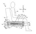
- FIG. 4is a sectional side view of the cushion assembly of FIG. 1 .
- a piece of furniture 10is illustrated according to various teachings of the present disclosure.
- the illustrated embodiment of the furniture 10is a couch, loveseat, or sofa, but it will be appreciated that the furniture could be a chair or any other suitable piece of furniture 10 without departing from the scope of the present disclosure.
- the furniture 10generally includes a plurality of cushions, including a plurality of back cushions 12 for supporting a back of a seated person 13 ( FIG. 4 ) and a plurality of seat cushion assemblies 14 for supporting the hips, thighs and/or other extremities of the person 13 ( FIG. 4 ).
- the cushion assemblies 14are discussed as being seat cushion assemblies 14 , it will be appreciated that the cushion assemblies 14 could be located in any suitable position on the furniture 10 without departing from the scope of the present disclosure.
- the cushion assemblies 14are configured to provide a great deal of comfort for the seated person 13 and can help the person 13 adjust positions and/or move off of the cushion assembly 14 .
- the cushion assembly 14can include a core layer 16 , a plurality of upper covering layers 18 a , a plurality of lower covering layers 18 b , and a filler layer 20 , each of which will be described in greater detail below.
- the core layer 16is disposed between the upper covering layers 18 a and the lower covering layers 18 b .
- the filler layer 20at least partially surrounds the upper and lower covering layers 18 a , 18 b and the core layer 16 .
- these layers 16 , 18 a , 18 b , 20can be encapsulated within a jacket 22 .
- the jacket 22can be made of a known upholstery material and can include artistic designs, textures, and the like for adding to the look and feel of the cushion assembly 14 .
- the cushion assembly 14will be discussed in greater detail. It will be appreciated that the back cushion 12 of the furniture 10 is shown in phantom for purposes of clarity. It will also be appreciated that the jacket 22 and filler layer 20 are also shown in phantom for purposes of clarity.
- the cushion assembly 14will be discussed in relation to a coordinate system X, Y, Z.
- the coordinate system X, Y, Zis arranged according to a thickness direction Z of the cushion assembly 14 and two transverse directions X, Y that are generally transverse (e.g., perpendicular) to the thickness direction Z. Specifically, the Y transverse direction extends generally forward and rearward on the cushion assembly 14 , and the X transverse direction extends generally side to side on the cushion assembly 14 .
- the cushion assembly 14generally includes a forward area 23 that includes a forward end 24 , a central area 25 , and a rearward end 26 .
- the central area 25is generally rearward from the forward area 23 along the Y direction
- the rearward end 26is rearward from the central area 25 along the Y direction.
- the assembly 14includes a first and second transverse side 28 a , 28 b , which extend generally transverse along the Y direction relative to the forward area 23 , the forward end 24 , and the rearward end 26 on opposite sides thereof.
- the cushion assembly 14includes an upper side 30 and a lower side 32 , which are opposite from each other along the thickness direction Z.
- the cushion assembly 14is generally rectangular and box-shaped. However, it will be appreciated that the cushion assembly 14 could be of any suitable shape without departing from the scope of the present disclosure. For instance, the cushion assembly 14 could be rounded, could include projections, and the like.
- the person 13typically sits on the upper side 30 and that the lower side 32 abuts a support frame, etc. (not shown) of the furniture 10 ( FIG. 4 ).
- a hip area 34 of the person 13is typically disposed over and supported by the central area 25 of the cushion assembly 14
- a lower thigh area 38 of the person 13is typically disposed over and supported by the forward area 23 and forward end 24 of the cushion assembly 14 .
- the forward and central areas 23 , 25 of the cushion assembly 14can be configured to provide improved support for the person 13 .
- the core layer 16can include a first member 40 , a second member 42 , and a third member 44 .
- the members 40 , 42 , 44can include and be made of foam.
- the members 40 , 42 , 44can be made of any suitable, resiliently deformable material.
- each of the members 40 , 42 , 44can have substantially the same thickness in the Z direction. It will be appreciated, however, that the members 40 , 42 , 44 could have any suitable thickness and shape without departing from the scope of the present disclosure.
- the first member 40can be elongate and rectangular, with a substantially straight axis extending along the X direction. In some embodiments, the first member 40 extends continuously between each of the transverse sides 28 a , 28 b of the cushion assembly 14 . Also, as shown, the first member 40 can be disposed adjacent the forward area 23 and the forward end 24 of the cushion assembly 14 , generally for supporting the lower thigh area 38 and/or lower legs of the person 13 .
- the second member 42can be elongate and rectangular, with a substantially straight axis extending along the X direction. In some embodiments, the second member 42 extends continuously between each of the transverse sides 28 a , 28 b of the cushion assembly 14 . Also, as shown, the second member 42 can be disposed rearward (in the Y direction) relative to the first member 40 . Specifically, in some embodiments, the second member 42 can be disposed adjacent to and abut a back surface 50 of the first member 40 . Also, in some embodiments, the second member 42 can be fixedly coupled to the back surface 50 of the first member 40 . The first and second members 40 , 42 can be fixedly coupled using any suitable means, such as adhesive, chemical bonding, pile tape, and the like. Moreover, the second member 42 can be disposed adjacent and within the central area 25 of the cushion assembly 14 , generally for supporting the hip area 34 of the person 13 .
- the third member 44can be elongate and rectangular, with a substantially straight axis extending along the X direction. In some embodiments, the third member 44 extends continuously between each of the transverse sides 28 a , 28 b of the cushion assembly 14 . Also, as shown, the third member 44 can be disposed rearward (in the Y direction) relative to the second member 42 . Specifically, in some embodiments, the third member 44 can be disposed adjacent to and abut a back surface 52 of the second member 42 . Also, in some embodiments, the third member 44 can be fixedly coupled to the back surface 52 of the second member 42 . The second and third members 42 , 44 can be fixedly coupled using any suitable means, such as adhesive, chemical bonding, pile tape, and the like. Moreover, the third member 44 can be disposed adjacent the rearward end 26 of the cushion assembly 14 such that the second member 42 is disposed between the first and third members 40 , 44 .
- the width of the third member 44is such that the back cushion 12 of the furniture 10 substantially covers the third member 44 and such that the person 13 is less likely to be directly supported by the third member 44 .
- the third member 44is not included, and the second member 42 extends continuously from the back surface 50 of the first member 40 to the rearward end 26 of the cushion assembly 14 .
- the upper covering layer 18 acan include a first upper covering layer 54 and a second upper covering layer 56 , each of which have generally rectangular, flat, box-like shapes.
- Each of the first and second upper covering layers 54 , 56can be thinner than the core layer 16 .
- the first and second upper covering layers 54 , 56can be made out of foam; however, it will be appreciated that the first and second upper covering layers 54 , 56 can be made out of any suitable resiliently deformable material.
- the first upper covering layer 54can be disposed adjacent the upper side 30 of the cushion assembly 14 and can abut and overlap the second upper covering layer 56 . Also, the second upper covering layer 56 can abut each of the first, second, and third members 40 , 42 , 44 of the core layer 16 . As such, the first and second upper covering layers 54 , 56 can span continuously across and collectively cover the first, second, and third members 40 , 42 , 44 of the core layer 16 in the X and Y transverse directions.
- the lower covering layer 18 bcan include a first lower covering layer 58 and a second lower covering layer 60 , each of which have generally rectangular, flat, box-like shapes.
- Each of the first and second lower covering layers 58 , 60can be thinner than the core layer 16 .
- the first and second lower covering layers 58 , 60can be made out of foam; however, it will be appreciated that the first and second lower covering layers 58 , 60 can be made out of any suitable resiliently deformable material.
- the first lower covering layer 58can be disposed adjacent the lower side 32 of the cushion assembly 14 and can abut and overlap the second lower covering layer 60 . Also, the second lower covering layer 58 can abut each of the first, second, and third members 40 , 42 , 44 of the core layer 16 . As such, the first and second lower covering layers 58 , 60 can span continuously across and collectively cover the first, second, and third members 40 , 42 , 44 of the core layer 16 in the X and Y transverse directions.
- the covering layers 54 , 56 , 58 , 60could be fixedly coupled to each other and/or to the core layer 16 via any suitable means, such as adhesive, chemical bonding, pile tape, and the like.
- the cushion assembly 14could include any number of covering layers 18 a , 18 b .
- the cushion assembly 14could include only one of the upper and lower covering layers 18 a , 18 b .
- the upper covering layer 18 acould include only one of the first and second upper covering layers 54 , 56
- the lower covering layer 18 bcould include only one of the first and second lower covering layers 58 , 60 .
- the filler layer 20can be a relatively thin sheet that continuously extends from the rearward end 26 of the upper side 30 of the cushion assembly 14 , across the central area 25 , across the forward end 24 , and across the lower side 32 to the rearward end 26 .
- the filler layer 20can be made out of any suitable soft material.
- the filler layer 20can be made out of and include batting material (i.e., cotton, wool, or synthetic sheets) or feathers.
- the core layer 16 and the upper and lower covering layers 18 a , 18 bcan be made out of a resiliently deformable material, such as foam. It will be appreciated that these layers 16 , 18 a , 18 b can be made out of any suitable foam, such as flexible, polyurethane foam.
- the layers 16can be configured to provide increased comfort for the person 13 seated on the cushion assembly 14 .
- the second member 42 of the core layer 16can have a higher resistance to resilient deformation than the first member 40 .
- the central area 25 of the cushion assembly 14i.e., the area likely to support the most weight of the person 13
- the cushion assembly 14is less likely to sag in the central area 25 , thereby allowing the person 13 to remain sitting upright on the cushion assembly 14 , to adjust his or her position, and to move off of the cushion assembly 14 .
- the first member 40 of the core layer 16is less firm, the cushion assembly 14 applies less pressure to the lower thigh area 38 of the person 13 for greater comfort.
- the first member 40can have a higher resistance to resilient deformation than the third member 44 . Also, the first member 40 can have a higher resistance to resilient deformation than any of the covering layers 54 , 56 , 58 , 60 . Accordingly, these characteristics can help distribute the weight loads of the person 13 to the core layer 16 for improved support.
- the resistance to resilient deformationis measured according to foam density and indentation force deflection (IFD) characteristics. These characteristics can be classified in a known manner, such as ASTM D3574.
- IFDindentation force deflection
- the second member 42has an indentation force deflection (IFD) characteristic above approximately 27 lb IFD, while the first member 40 has an IFD characteristic above approximately 24 lb IFD.
- IFDindentation force deflection
- the second member 42has a density of 2.5 pounds per cubic foot (pcf) and between 35 lb and 40 lb IFD
- the first member 40has a density of approximately 1.8 pcf and between 25 lb and 30 lb IFD
- the first member 40has a density of approximately 1.8 pcf and 27 lb IFD
- the second member 42has a density of approximately 2.5 pcf and 36 lb IFD
- the third member 44has a density of approximately 1.8 pcf and 23 lb IFD
- the second upper covering layer 56 and the second lower covering layereach have a density of approximately 1.8 pcf and 24 lb IFD
- the first upper covering layer 54 and first lower covering layer 58each have a density of approximately 1.8 pcf and 12 IFD.
- Example embodimentsare provided so that this disclosure will be thorough, and will fully convey the scope to those who are skilled in the art. Numerous specific details are set forth such as examples of specific components, devices, and methods, to provide a thorough understanding of embodiments of the present disclosure. It will be apparent to those skilled in the art that specific details need not be employed, that example embodiments may be embodied in many different forms and that neither should be construed to limit the scope of the disclosure. In some example embodiments, well-known processes, well-known device structures, and well-known technologies are not described in detail.
- first, second, third, etc.may be used herein to describe various elements, components, regions, layers and/or sections, these elements, components, regions, layers and/or sections should not be limited by these terms. These terms may be only used to distinguish one element, component, region, layer or section from another region, layer or section. Terms such as “first,” “second,” and other numerical terms when used herein do not imply a sequence or order unless clearly indicated by the context. Thus, a first element, component, region, layer or section discussed below could be termed a second element, component, region, layer or section without departing from the teachings of the example embodiments.
Landscapes
- Mattresses And Other Support Structures For Chairs And Beds (AREA)
- Casting Or Compression Moulding Of Plastics Or The Like (AREA)
- Laminated Bodies (AREA)
Abstract
Description
Claims (11)
Priority Applications (10)
| Application Number | Priority Date | Filing Date | Title |
|---|---|---|---|
| US12/334,767US8141957B2 (en) | 2008-12-15 | 2008-12-15 | Cushion with plural zones of foam |
| AU2009330579AAU2009330579A1 (en) | 2008-12-15 | 2009-11-19 | Cushion with plural zones of foam |
| EP09835451AEP2365767B1 (en) | 2008-12-15 | 2009-11-19 | Cushion with plural zones of foam |
| PCT/US2009/065136WO2010074850A2 (en) | 2008-12-15 | 2009-11-19 | Cushion with plural zones of foam |
| CN200980150427.7ACN102245057B (en) | 2008-12-15 | 2009-11-19 | Cushion with plural zones of foam |
| BRPI0919699ABRPI0919699A2 (en) | 2008-12-15 | 2009-11-19 | cushion set, and method of manufacturing a cushion set. |
| CA2740956ACA2740956C (en) | 2008-12-15 | 2009-11-19 | Cushion with plural zones of foam |
| MX2011004022AMX2011004022A (en) | 2008-12-15 | 2009-11-19 | Cushion with plural zones of foam. |
| NZ592334ANZ592334A (en) | 2008-12-15 | 2009-11-19 | Cushion with multiple zones of foam having differing resistance to resilient deformation |
| ZA2011/02902AZA201102902B (en) | 2008-12-15 | 2011-04-18 | Cushion with plural zones of foam |
Applications Claiming Priority (1)
| Application Number | Priority Date | Filing Date | Title |
|---|---|---|---|
| US12/334,767US8141957B2 (en) | 2008-12-15 | 2008-12-15 | Cushion with plural zones of foam |
Publications (2)
| Publication Number | Publication Date |
|---|---|
| US20100148562A1 US20100148562A1 (en) | 2010-06-17 |
| US8141957B2true US8141957B2 (en) | 2012-03-27 |
Family
ID=42239616
Family Applications (1)
| Application Number | Title | Priority Date | Filing Date |
|---|---|---|---|
| US12/334,767Active2029-09-18US8141957B2 (en) | 2008-12-15 | 2008-12-15 | Cushion with plural zones of foam |
Country Status (10)
| Country | Link |
|---|---|
| US (1) | US8141957B2 (en) |
| EP (1) | EP2365767B1 (en) |
| CN (1) | CN102245057B (en) |
| AU (1) | AU2009330579A1 (en) |
| BR (1) | BRPI0919699A2 (en) |
| CA (1) | CA2740956C (en) |
| MX (1) | MX2011004022A (en) |
| NZ (1) | NZ592334A (en) |
| WO (1) | WO2010074850A2 (en) |
| ZA (1) | ZA201102902B (en) |
Cited By (19)
| Publication number | Priority date | Publication date | Assignee | Title |
|---|---|---|---|---|
| US20110221257A1 (en)* | 2010-03-11 | 2011-09-15 | Honda Motor Co., Ltd. | Vehicle seat assembly |
| US20110221254A1 (en)* | 2010-03-11 | 2011-09-15 | Honda Motor Co., Ltd. | Vehicle seat assembly |
| US20120080915A1 (en)* | 2010-10-01 | 2012-04-05 | Porter And Davies Limited | Vibration seat |
| US20120248845A1 (en)* | 2011-04-01 | 2012-10-04 | Kevin Charles Furniture, Llc | Cushion |
| US8408655B2 (en) | 2010-08-27 | 2013-04-02 | Honda Motor Co., Ltd. | Vehicle seat assembly |
| US20130111672A1 (en)* | 2011-11-01 | 2013-05-09 | Bob Rensink | Mattresses Having a Matrix Core of Foam Elements |
| US8439440B2 (en) | 2010-08-27 | 2013-05-14 | Honda Motor Co., Ltd. | Vehicle seat assembly |
| US20130175838A1 (en)* | 2010-10-01 | 2013-07-11 | Nissan Motor Co., Ltd. | Vehicle seat and stiffness setting method for vehicle seat |
| US20140077550A1 (en)* | 2012-09-14 | 2014-03-20 | Toyota Boshoku Kabushiki Kaisha | Vehicle seat |
| US20140223666A1 (en)* | 2013-02-04 | 2014-08-14 | David R. Pavlin | Skin irritant reduction cushioning construction |
| US20150202541A1 (en)* | 2014-01-23 | 2015-07-23 | Zinus Inc. | Giant Children's Foam Blocks Molded Around A Rigid Inner Core |
| US20150335168A1 (en)* | 2014-05-23 | 2015-11-26 | American Signature, Inc. | Composite Seat Cushion |
| US20160114712A1 (en)* | 2013-05-23 | 2016-04-28 | Proprietect L.P. | Padded Element, and Process and Mold for Producing Same |
| US9420891B2 (en) | 2013-11-29 | 2016-08-23 | Zinus, Inc. | Foam furniture molded around a rigid foam core |
| US9456696B2 (en) | 2013-11-29 | 2016-10-04 | Zinus, Inc. | Foam furniture molded around a core with a lumbar support protrusion |
| US10271657B2 (en) | 2013-11-29 | 2019-04-30 | Zinus Inc. | Foam furniture molded around a hollow shell of hard plastic |
| US10427571B2 (en)* | 2015-02-27 | 2019-10-01 | Proprietect L.P. | Vehicular seat element |
| US10537186B2 (en) | 2011-11-01 | 2020-01-21 | Denver Mattress Co., Llc | Upcycled mattress nucleus of essential foam elements |
| USRE48673E1 (en)* | 2015-09-24 | 2021-08-10 | Max Home, Llc | Seating sofa with laminated readily reboundable cooling-effect seating cushions |
Families Citing this family (9)
| Publication number | Priority date | Publication date | Assignee | Title |
|---|---|---|---|---|
| FR2972615B1 (en)* | 2011-03-14 | 2013-03-08 | Fabienne Sportis | NEW ADAPTIVE MATTRESS AND METHOD FOR MANUFACTURING THE SAME |
| RU2014102480A (en)* | 2011-07-14 | 2015-08-20 | Проприетэкт Эл.Пи. | ELEMENT OF FOAM SEAT SEAT, AND ALSO METHOD AND FORM FOR ITS PRODUCTION |
| CN104602569A (en)* | 2012-08-23 | 2015-05-06 | 李尔公司 | Chest area comfort seating system |
| US20140212625A1 (en)* | 2012-08-26 | 2014-07-31 | Maria Estela Seitz | Light weight rotective clothing and accessories |
| JP6675822B2 (en)* | 2014-07-24 | 2020-04-08 | 株式会社東洋クオリティワン | Manufacturing method of cushion pad |
| JP6572801B2 (en)* | 2016-03-03 | 2019-09-11 | テイ・エス テック株式会社 | Vehicle seat |
| US10457175B2 (en)* | 2017-08-15 | 2019-10-29 | GM Global Technology Operations LLC | Cushion with spatially varying lattice structures |
| WO2019089914A1 (en)* | 2017-11-01 | 2019-05-09 | Bedgear, Llc | Mattress assembly |
| CN110991035B (en)* | 2019-11-29 | 2023-05-05 | 大自然科技股份有限公司 | Design method of palm mattress lightweight structure |
Citations (47)
| Publication number | Priority date | Publication date | Assignee | Title |
|---|---|---|---|---|
| US3278955A (en)* | 1964-06-11 | 1966-10-18 | Dayco Corp | Foam rubber article |
| US3833259A (en) | 1972-05-30 | 1974-09-03 | Deere & Co | Vehicle seat comprising three foam layers |
| US3987507A (en) | 1975-08-25 | 1976-10-26 | Everest & Jennings, Inc. | Pressure distribution pad assembly for wheelchairs |
| US4190697A (en) | 1979-01-15 | 1980-02-26 | Milsco Manufacturing Company | Multidensity foam article and method of preparation |
| WO1981002384A1 (en)* | 1980-02-19 | 1981-09-03 | Jourdan Thomas Ltd | Mattress |
| US4379856A (en) | 1981-01-23 | 1983-04-12 | Bayer Aktiengesellschaft | Polyurethane foam molding with zones of different indentation hardness and a process for its production |
| US4405681A (en) | 1983-01-20 | 1983-09-20 | Milsco Manufacturing Company | Foam article and method of preparation |
| US4522447A (en) | 1980-02-02 | 1985-06-11 | Snyder William F | Foam seat and back cushions |
| US4682818A (en)* | 1986-08-14 | 1987-07-28 | Morell Theodore R | Pressure distribution pad assembly for wheelchairs |
| US4753480A (en)* | 1986-08-14 | 1988-06-28 | Morell Theodore R | Pad assembly for wheelchairs |
| US4755411A (en) | 1987-04-22 | 1988-07-05 | Milsco Limited | Cushion having flexible outer membrane and multi-density resilient foam member therein |
| US4819288A (en) | 1986-08-06 | 1989-04-11 | National Research Development Corporation | Cushions |
| US4837881A (en) | 1986-12-02 | 1989-06-13 | Nissan Motor Co., Ltd. | Seat cushion with portions with different compression characteristics |
| US4951334A (en)* | 1989-07-26 | 1990-08-28 | Maier Edmund K | Pressure relief cushion |
| US5018790A (en)* | 1988-07-20 | 1991-05-28 | Jay Medical, Ltd. | Customized seat cushion |
| GB2244000A (en)* | 1990-05-18 | 1991-11-20 | Teasdale S | Mattress |
| US5137333A (en) | 1990-01-25 | 1992-08-11 | Rolliture Corporation | Seat cushion |
| DE4140935A1 (en)* | 1991-12-12 | 1993-07-01 | Naue Gmbh & Co Kg | Vehicle seat with two layers of upholstery - has coconut mat inserted between layers to prevent seating effect. |
| US5294181A (en)* | 1992-01-07 | 1994-03-15 | E. R. Carpenter Company, Inc. | Seat cushion |
| US5327596A (en) | 1993-07-29 | 1994-07-12 | Hickory Springs Manufacturing Company | Combination spring/foam cushioning |
| US5442823A (en) | 1993-01-06 | 1995-08-22 | Invacare Corporation | Wheelchair cushion utilizing foams of different stiffnesses |
| JPH07317286A (en) | 1994-05-27 | 1995-12-05 | Eidai Co Ltd | Floor cosmetics |
| US5474362A (en) | 1991-06-26 | 1995-12-12 | Albecker, Iii; Walter J. | Cushions having internal support member |
| US5632053A (en)* | 1991-04-22 | 1997-05-27 | C.A. Greiner & Sohne Gesellschaft M.B.H. | Vehicle seat cushion |
| US6175980B1 (en)* | 1999-01-21 | 2001-01-23 | Alma Gaither | Ergonomic seat cushion for reducing and absorbing shock and vibration |
| US6202239B1 (en)* | 1998-02-25 | 2001-03-20 | Select Comfort Corp. | Multi-zone support |
| US6237173B1 (en)* | 1999-03-15 | 2001-05-29 | August Lotz Co., Inc. | Articulated foam futon mattress |
| US6269504B1 (en)* | 1998-05-06 | 2001-08-07 | Hill-Rom Services, Inc. | Mattress or cushion structure |
| US6286166B1 (en)* | 1998-06-19 | 2001-09-11 | Hill-Rom Services, Inc. | Modular foam mattress |
| US6292965B1 (en)* | 2000-10-05 | 2001-09-25 | Dwain P Gambrell | Mattress |
| US6336681B1 (en)* | 1998-05-18 | 2002-01-08 | Robert Andrew Crosbie | Chair and seat cushion therefor |
| USD456197S1 (en)* | 2001-03-30 | 2002-04-30 | Carpenter Co. | Mattress pad configuration |
| US6516483B1 (en)* | 2000-03-28 | 2003-02-11 | The Or Group, Inc. | Patient support surface |
| US6807698B2 (en)* | 2002-06-01 | 2004-10-26 | Sleepadvantage, Llc | Bed having low body pressure and alignment |
| US6918146B2 (en)* | 2003-06-19 | 2005-07-19 | England, Inc. | Adjustable seat cushion for furniture |
| US6952852B2 (en)* | 1995-11-30 | 2005-10-11 | Hill-Rom Services, Inc. | Mattress structure |
| US6957465B1 (en)* | 2004-08-17 | 2005-10-25 | Oprandi Arthur V | Mattress pad |
| US20060273650A1 (en)* | 2005-06-01 | 2006-12-07 | Embach James T | Foam cushion having a progressively increasing spring constant |
| US20060272098A1 (en)* | 2005-06-03 | 2006-12-07 | Hochschild Arthur A | Composite foam mattress assembly |
| US20060288490A1 (en)* | 2005-06-24 | 2006-12-28 | Tempur World, Llc | Reticulated material body support and method |
| US20070022540A1 (en)* | 2005-06-03 | 2007-02-01 | Hochschild Arthur A | Composite mattress assembly and method for adjusting the same |
| US20070044241A1 (en)* | 2005-08-29 | 2007-03-01 | Clark John D | Discrete orthoganol support system |
| US7238630B2 (en) | 2003-02-05 | 2007-07-03 | L&P Property Management Company | Cushion having plural zones with discrete compressibility characteristics |
| US20070209120A1 (en) | 2005-08-29 | 2007-09-13 | Clark John D | Discrete orthoganol support system |
| US7905552B2 (en)* | 2006-07-20 | 2011-03-15 | Lear Corporation | Environmentally friendly layered seating assembly |
| US8020230B2 (en)* | 2006-08-29 | 2011-09-20 | Hsiu Chen Liao | Foam spring mattress with substantially horizontal straps |
| US20110277246A1 (en)* | 2009-01-23 | 2011-11-17 | Backjoy Orthotics, Llc | Method and apparatus for dynamically correcting posture |
Family Cites Families (6)
| Publication number | Priority date | Publication date | Assignee | Title |
|---|---|---|---|---|
| ES350735A1 (en)* | 1968-02-21 | 1969-05-01 | Colchones Anatomicos Espanola | Mattress for clinical and other purposes |
| NL9302043A (en)* | 1993-11-25 | 1995-06-16 | Recticel Nederland Bv | Two-piece core mattress with taper towards the center. |
| JP2006204887A (en)* | 2004-12-28 | 2006-08-10 | Bridgestone Corp | Seat cushion pad, seat back pad, and seat for vehicle |
| EP1787549B1 (en) | 2005-11-18 | 2013-01-16 | Sponsor S.r.L. | Sitting cushion with improved comfort |
| JP4836678B2 (en)* | 2006-06-16 | 2011-12-14 | 株式会社イノアックコーポレーション | Cushion body manufacturing method |
| EP1905404B1 (en)* | 2006-09-29 | 2010-03-31 | Sunrise Medical HHG Inc. | Wheelchair seat cushion |
- 2008
- 2008-12-15USUS12/334,767patent/US8141957B2/enactiveActive
- 2009
- 2009-11-19MXMX2011004022Apatent/MX2011004022A/enactiveIP Right Grant
- 2009-11-19AUAU2009330579Apatent/AU2009330579A1/ennot_activeAbandoned
- 2009-11-19CACA2740956Apatent/CA2740956C/enactiveActive
- 2009-11-19WOPCT/US2009/065136patent/WO2010074850A2/enactiveApplication Filing
- 2009-11-19BRBRPI0919699Apatent/BRPI0919699A2/ennot_activeIP Right Cessation
- 2009-11-19CNCN200980150427.7Apatent/CN102245057B/ennot_activeExpired - Fee Related
- 2009-11-19EPEP09835451Apatent/EP2365767B1/ennot_activeNot-in-force
- 2009-11-19NZNZ592334Apatent/NZ592334A/ennot_activeIP Right Cessation
- 2011
- 2011-04-18ZAZA2011/02902Apatent/ZA201102902B/enunknown
Patent Citations (52)
| Publication number | Priority date | Publication date | Assignee | Title |
|---|---|---|---|---|
| US3278955A (en)* | 1964-06-11 | 1966-10-18 | Dayco Corp | Foam rubber article |
| US3833259A (en) | 1972-05-30 | 1974-09-03 | Deere & Co | Vehicle seat comprising three foam layers |
| US3987507A (en) | 1975-08-25 | 1976-10-26 | Everest & Jennings, Inc. | Pressure distribution pad assembly for wheelchairs |
| US4190697A (en) | 1979-01-15 | 1980-02-26 | Milsco Manufacturing Company | Multidensity foam article and method of preparation |
| US4522447A (en) | 1980-02-02 | 1985-06-11 | Snyder William F | Foam seat and back cushions |
| WO1981002384A1 (en)* | 1980-02-19 | 1981-09-03 | Jourdan Thomas Ltd | Mattress |
| US4379856A (en) | 1981-01-23 | 1983-04-12 | Bayer Aktiengesellschaft | Polyurethane foam molding with zones of different indentation hardness and a process for its production |
| US4405681A (en) | 1983-01-20 | 1983-09-20 | Milsco Manufacturing Company | Foam article and method of preparation |
| US4819288A (en) | 1986-08-06 | 1989-04-11 | National Research Development Corporation | Cushions |
| US4682818A (en)* | 1986-08-14 | 1987-07-28 | Morell Theodore R | Pressure distribution pad assembly for wheelchairs |
| US4753480A (en)* | 1986-08-14 | 1988-06-28 | Morell Theodore R | Pad assembly for wheelchairs |
| US4837881A (en) | 1986-12-02 | 1989-06-13 | Nissan Motor Co., Ltd. | Seat cushion with portions with different compression characteristics |
| US4755411A (en) | 1987-04-22 | 1988-07-05 | Milsco Limited | Cushion having flexible outer membrane and multi-density resilient foam member therein |
| US5018790A (en)* | 1988-07-20 | 1991-05-28 | Jay Medical, Ltd. | Customized seat cushion |
| US4951334A (en)* | 1989-07-26 | 1990-08-28 | Maier Edmund K | Pressure relief cushion |
| US5137333A (en) | 1990-01-25 | 1992-08-11 | Rolliture Corporation | Seat cushion |
| GB2244000A (en)* | 1990-05-18 | 1991-11-20 | Teasdale S | Mattress |
| US5632053A (en)* | 1991-04-22 | 1997-05-27 | C.A. Greiner & Sohne Gesellschaft M.B.H. | Vehicle seat cushion |
| US5474362A (en) | 1991-06-26 | 1995-12-12 | Albecker, Iii; Walter J. | Cushions having internal support member |
| DE4140935A1 (en)* | 1991-12-12 | 1993-07-01 | Naue Gmbh & Co Kg | Vehicle seat with two layers of upholstery - has coconut mat inserted between layers to prevent seating effect. |
| US5294181A (en)* | 1992-01-07 | 1994-03-15 | E. R. Carpenter Company, Inc. | Seat cushion |
| US5442823A (en) | 1993-01-06 | 1995-08-22 | Invacare Corporation | Wheelchair cushion utilizing foams of different stiffnesses |
| US5327596A (en) | 1993-07-29 | 1994-07-12 | Hickory Springs Manufacturing Company | Combination spring/foam cushioning |
| JPH07317286A (en) | 1994-05-27 | 1995-12-05 | Eidai Co Ltd | Floor cosmetics |
| US6952852B2 (en)* | 1995-11-30 | 2005-10-11 | Hill-Rom Services, Inc. | Mattress structure |
| US6202239B1 (en)* | 1998-02-25 | 2001-03-20 | Select Comfort Corp. | Multi-zone support |
| US6269504B1 (en)* | 1998-05-06 | 2001-08-07 | Hill-Rom Services, Inc. | Mattress or cushion structure |
| US6701556B2 (en)* | 1998-05-06 | 2004-03-09 | Hill-Rom Services, Inc. | Mattress or cushion structure |
| US6336681B1 (en)* | 1998-05-18 | 2002-01-08 | Robert Andrew Crosbie | Chair and seat cushion therefor |
| US6286166B1 (en)* | 1998-06-19 | 2001-09-11 | Hill-Rom Services, Inc. | Modular foam mattress |
| US6175980B1 (en)* | 1999-01-21 | 2001-01-23 | Alma Gaither | Ergonomic seat cushion for reducing and absorbing shock and vibration |
| US6237173B1 (en)* | 1999-03-15 | 2001-05-29 | August Lotz Co., Inc. | Articulated foam futon mattress |
| US6516483B1 (en)* | 2000-03-28 | 2003-02-11 | The Or Group, Inc. | Patient support surface |
| US6292965B1 (en)* | 2000-10-05 | 2001-09-25 | Dwain P Gambrell | Mattress |
| USD456197S1 (en)* | 2001-03-30 | 2002-04-30 | Carpenter Co. | Mattress pad configuration |
| US6807698B2 (en)* | 2002-06-01 | 2004-10-26 | Sleepadvantage, Llc | Bed having low body pressure and alignment |
| US7238630B2 (en) | 2003-02-05 | 2007-07-03 | L&P Property Management Company | Cushion having plural zones with discrete compressibility characteristics |
| US6918146B2 (en)* | 2003-06-19 | 2005-07-19 | England, Inc. | Adjustable seat cushion for furniture |
| US6957465B1 (en)* | 2004-08-17 | 2005-10-25 | Oprandi Arthur V | Mattress pad |
| US20060273650A1 (en)* | 2005-06-01 | 2006-12-07 | Embach James T | Foam cushion having a progressively increasing spring constant |
| US20060272098A1 (en)* | 2005-06-03 | 2006-12-07 | Hochschild Arthur A | Composite foam mattress assembly |
| US20070022540A1 (en)* | 2005-06-03 | 2007-02-01 | Hochschild Arthur A | Composite mattress assembly and method for adjusting the same |
| US20060288490A1 (en)* | 2005-06-24 | 2006-12-28 | Tempur World, Llc | Reticulated material body support and method |
| US20070044241A1 (en)* | 2005-08-29 | 2007-03-01 | Clark John D | Discrete orthoganol support system |
| US20070209120A1 (en) | 2005-08-29 | 2007-09-13 | Clark John D | Discrete orthoganol support system |
| US7905552B2 (en)* | 2006-07-20 | 2011-03-15 | Lear Corporation | Environmentally friendly layered seating assembly |
| US8020230B2 (en)* | 2006-08-29 | 2011-09-20 | Hsiu Chen Liao | Foam spring mattress with substantially horizontal straps |
| US20110239374A1 (en)* | 2006-08-29 | 2011-10-06 | Rawls-Meehan Martin B | Foam spring mattress configured with variable firmness |
| US20110252569A1 (en)* | 2006-08-29 | 2011-10-20 | Rawls-Meehan Martin B | Reconfigurable mattress |
| US20110258784A1 (en)* | 2006-08-29 | 2011-10-27 | Rawls-Meehan Martin B | Using a software application to configure a foam spring mattress |
| US20110283462A1 (en)* | 2006-08-29 | 2011-11-24 | Rawls-Meehan Martin B | Using a software application to configure a foam spring mattress |
| US20110277246A1 (en)* | 2009-01-23 | 2011-11-17 | Backjoy Orthotics, Llc | Method and apparatus for dynamically correcting posture |
Non-Patent Citations (2)
| Title |
|---|
| International Search Report for International Application No. PCT/US2009/065136 mailed Jul. 1,2010. |
| Written Opinion of the International Searching Authority for International Application No. PCT/US2009/065136 mailed Jul. 1, 2010. |
Cited By (29)
| Publication number | Priority date | Publication date | Assignee | Title |
|---|---|---|---|---|
| US8308235B2 (en) | 2010-03-11 | 2012-11-13 | Honda Motor Co. | Vehicle seat assembly |
| US20110221254A1 (en)* | 2010-03-11 | 2011-09-15 | Honda Motor Co., Ltd. | Vehicle seat assembly |
| US20110221257A1 (en)* | 2010-03-11 | 2011-09-15 | Honda Motor Co., Ltd. | Vehicle seat assembly |
| US8398166B2 (en)* | 2010-03-11 | 2013-03-19 | Honda Motor Co., Ltd. | Vehicle seat assembly |
| US8439440B2 (en) | 2010-08-27 | 2013-05-14 | Honda Motor Co., Ltd. | Vehicle seat assembly |
| US8408655B2 (en) | 2010-08-27 | 2013-04-02 | Honda Motor Co., Ltd. | Vehicle seat assembly |
| US20120080915A1 (en)* | 2010-10-01 | 2012-04-05 | Porter And Davies Limited | Vibration seat |
| US10543764B2 (en)* | 2010-10-01 | 2020-01-28 | Nissan Motor Co., Ltd. | Vehicle seat and stiffness setting method for vehicle seat |
| US20130175838A1 (en)* | 2010-10-01 | 2013-07-11 | Nissan Motor Co., Ltd. | Vehicle seat and stiffness setting method for vehicle seat |
| US8622471B2 (en)* | 2010-10-01 | 2014-01-07 | Porter And Davies Limited | Vibration seat |
| US20120248845A1 (en)* | 2011-04-01 | 2012-10-04 | Kevin Charles Furniture, Llc | Cushion |
| US8491056B2 (en)* | 2011-04-01 | 2013-07-23 | Kevin Charles Furniture, Llc | Cushion |
| US11140996B2 (en) | 2011-11-01 | 2021-10-12 | Denver Mattress Co., Llc | Upcycled mattress nucleus of essential foam elements |
| US10537186B2 (en) | 2011-11-01 | 2020-01-21 | Denver Mattress Co., Llc | Upcycled mattress nucleus of essential foam elements |
| US20130111672A1 (en)* | 2011-11-01 | 2013-05-09 | Bob Rensink | Mattresses Having a Matrix Core of Foam Elements |
| US20140077550A1 (en)* | 2012-09-14 | 2014-03-20 | Toyota Boshoku Kabushiki Kaisha | Vehicle seat |
| US9604549B2 (en)* | 2012-09-14 | 2017-03-28 | Toyota Boshoku Kabushiki Kaisha | Vehicle seat |
| US20140223666A1 (en)* | 2013-02-04 | 2014-08-14 | David R. Pavlin | Skin irritant reduction cushioning construction |
| US10252655B2 (en)* | 2013-05-23 | 2019-04-09 | Proprietect L.P. | Padded element, and process and mold for producing same |
| US20160114712A1 (en)* | 2013-05-23 | 2016-04-28 | Proprietect L.P. | Padded Element, and Process and Mold for Producing Same |
| US9456696B2 (en) | 2013-11-29 | 2016-10-04 | Zinus, Inc. | Foam furniture molded around a core with a lumbar support protrusion |
| US9420891B2 (en) | 2013-11-29 | 2016-08-23 | Zinus, Inc. | Foam furniture molded around a rigid foam core |
| US10271657B2 (en) | 2013-11-29 | 2019-04-30 | Zinus Inc. | Foam furniture molded around a hollow shell of hard plastic |
| US10201764B2 (en)* | 2014-01-23 | 2019-02-12 | Zinus Inc. | Giant children's foam blocks molded around a rigid inner core |
| US20150202541A1 (en)* | 2014-01-23 | 2015-07-23 | Zinus Inc. | Giant Children's Foam Blocks Molded Around A Rigid Inner Core |
| US20150335168A1 (en)* | 2014-05-23 | 2015-11-26 | American Signature, Inc. | Composite Seat Cushion |
| US10427571B2 (en)* | 2015-02-27 | 2019-10-01 | Proprietect L.P. | Vehicular seat element |
| US11059405B2 (en) | 2015-02-27 | 2021-07-13 | Proprietect L.P. | Vehicular seat element |
| USRE48673E1 (en)* | 2015-09-24 | 2021-08-10 | Max Home, Llc | Seating sofa with laminated readily reboundable cooling-effect seating cushions |
Also Published As
| Publication number | Publication date |
|---|---|
| EP2365767B1 (en) | 2013-02-13 |
| EP2365767A2 (en) | 2011-09-21 |
| ZA201102902B (en) | 2012-06-27 |
| AU2009330579A1 (en) | 2010-07-01 |
| NZ592334A (en) | 2012-11-30 |
| WO2010074850A2 (en) | 2010-07-01 |
| CA2740956C (en) | 2014-05-13 |
| US20100148562A1 (en) | 2010-06-17 |
| CN102245057B (en) | 2014-09-17 |
| WO2010074850A3 (en) | 2010-08-26 |
| BRPI0919699A2 (en) | 2015-12-08 |
| CN102245057A (en) | 2011-11-16 |
| CA2740956A1 (en) | 2010-07-01 |
| MX2011004022A (en) | 2011-05-25 |
| EP2365767A4 (en) | 2012-06-06 |
Similar Documents
| Publication | Publication Date | Title |
|---|---|---|
| US8141957B2 (en) | Cushion with plural zones of foam | |
| CA2542598C (en) | Pillow top for a cushion | |
| US6662393B2 (en) | Composite mattress | |
| US7210181B1 (en) | Spring construction | |
| AU2009346387A1 (en) | Mattress with quilted zoned topper | |
| US20060022506A1 (en) | Pressure equalizing mesh | |
| US20110047707A1 (en) | Surface impression removal technology system | |
| RU54497U1 (en) | SOFT BASIS OF FURNITURE ELEMENT | |
| JP5871377B2 (en) | Mattress cushion | |
| JP2003289999A (en) | Cushion material | |
| KR100401331B1 (en) | A mattress having different hardness for human body | |
| CN201223180Y (en) | Chair cushion and chair with the same | |
| JP6823775B2 (en) | Cushion arrangement structure | |
| JP3167964U (en) | Wheelchair cushion | |
| JP6198758B2 (en) | sofa | |
| JP3109026B2 (en) | sofa | |
| JP2016144490A (en) | sofa | |
| JPH05115341A (en) | Sitting device | |
| JPH11299583A (en) | Mattress equipment | |
| KR20240069021A (en) | A mattress for sofa, and bed-type sofa comprising the same | |
| EP0959738A1 (en) | Bed base | |
| MXPA06004247A (en) | Pillow top for a cushion |
Legal Events
| Date | Code | Title | Description |
|---|---|---|---|
| AS | Assignment | Owner name:LA-Z-BOY INCORPORATED,MICHIGAN Free format text:ASSIGNMENT OF ASSIGNORS INTEREST;ASSIGNORS:MCCLUNG, MARK D.;MCCLURE, THEODORE R.;HAWKINS, STEVEN D.;SIGNING DATES FROM 20081118 TO 20081121;REEL/FRAME:021981/0680 Owner name:LA-Z-BOY INCORPORATED, MICHIGAN Free format text:ASSIGNMENT OF ASSIGNORS INTEREST;ASSIGNORS:MCCLUNG, MARK D.;MCCLURE, THEODORE R.;HAWKINS, STEVEN D.;SIGNING DATES FROM 20081118 TO 20081121;REEL/FRAME:021981/0680 | |
| AS | Assignment | Owner name:WACHOVIA CAPITAL FINANCE CORPORATION (CENTRAL), AS Free format text:SECURITY AGREEMENT;ASSIGNOR:LA-Z-BOY INCORPORATED;REEL/FRAME:022782/0665 Effective date:20090529 | |
| AS | Assignment | Owner name:LA-Z--BOY INCORPORATED, MICHIGAN Free format text:RELEASE BY SECURED PARTY;ASSIGNOR:WELLS FARGO CAPITAL FINANCE LLC (AS SUCCESSOR BY MERGER TO WACHOVIA CAPITAL FINANCE CORPORATION);REEL/FRAME:027265/0717 Effective date:20111019 | |
| STCF | Information on status: patent grant | Free format text:PATENTED CASE | |
| FPAY | Fee payment | Year of fee payment:4 | |
| MAFP | Maintenance fee payment | Free format text:PAYMENT OF MAINTENANCE FEE, 8TH YEAR, LARGE ENTITY (ORIGINAL EVENT CODE: M1552); ENTITY STATUS OF PATENT OWNER: LARGE ENTITY Year of fee payment:8 | |
| MAFP | Maintenance fee payment | Free format text:PAYMENT OF MAINTENANCE FEE, 12TH YEAR, LARGE ENTITY (ORIGINAL EVENT CODE: M1553); ENTITY STATUS OF PATENT OWNER: LARGE ENTITY Year of fee payment:12 |