US8141424B2 - Low inertia frame for detecting coriolis acceleration - Google Patents
Low inertia frame for detecting coriolis accelerationDownload PDFInfo
- Publication number
- US8141424B2 US8141424B2US12/210,045US21004508AUS8141424B2US 8141424 B2US8141424 B2US 8141424B2US 21004508 AUS21004508 AUS 21004508AUS 8141424 B2US8141424 B2US 8141424B2
- Authority
- US
- United States
- Prior art keywords
- rail
- frame
- axis
- guiding arm
- sensing
- Prior art date
- Legal status (The legal status is an assumption and is not a legal conclusion. Google has not performed a legal analysis and makes no representation as to the accuracy of the status listed.)
- Active, expires
Links
- 230000001133accelerationEffects0.000titleabstractdescription7
- 238000004873anchoringMethods0.000claimsabstractdescription25
- 230000008878couplingEffects0.000claimsabstractdescription11
- 238000010168coupling processMethods0.000claimsabstractdescription11
- 238000005859coupling reactionMethods0.000claimsabstractdescription11
- 230000004044responseEffects0.000claimsabstractdescription4
- 230000035945sensitivityEffects0.000description24
- 238000000034methodMethods0.000description7
- 230000008901benefitEffects0.000description6
- 230000003071parasitic effectEffects0.000description4
- 230000010355oscillationEffects0.000description3
- 230000000694effectsEffects0.000description2
- 230000005484gravityEffects0.000description2
- 238000012986modificationMethods0.000description2
- 230000004048modificationEffects0.000description2
- 239000000758substrateSubstances0.000description2
- 230000004308accommodationEffects0.000description1
- 230000005540biological transmissionEffects0.000description1
- 230000003247decreasing effectEffects0.000description1
- 230000000593degrading effectEffects0.000description1
- 230000009977dual effectEffects0.000description1
- 230000014509gene expressionEffects0.000description1
- 230000007246mechanismEffects0.000description1
- 238000004806packaging method and processMethods0.000description1
- 230000009467reductionEffects0.000description1
- 239000000725suspensionSubstances0.000description1
- 230000002459sustained effectEffects0.000description1
- 239000002699waste materialSubstances0.000description1
Images


Classifications
- G—PHYSICS
- G01—MEASURING; TESTING
- G01C—MEASURING DISTANCES, LEVELS OR BEARINGS; SURVEYING; NAVIGATION; GYROSCOPIC INSTRUMENTS; PHOTOGRAMMETRY OR VIDEOGRAMMETRY
- G01C19/00—Gyroscopes; Turn-sensitive devices using vibrating masses; Turn-sensitive devices without moving masses; Measuring angular rate using gyroscopic effects
- G01C19/56—Turn-sensitive devices using vibrating masses, e.g. vibratory angular rate sensors based on Coriolis forces
- G01C19/5719—Turn-sensitive devices using vibrating masses, e.g. vibratory angular rate sensors based on Coriolis forces using planar vibrating masses driven in a translation vibration along an axis
Definitions
- the present inventionrelates to angular velocity sensors, and more particularly to the sensing frame of in-plane angular velocity sensors.
- a vibratory angular rate sensorcomprises drive and sense subsystems.
- the drive subsystemis driven into oscillation at the resonant frequency of the drive mode.
- the Coriolis forceacts on the oscillating drive subsystem and generated force which is then transferred to the sense subsystem. Consequently, the sense subsystem moves at the drive frequency proportional to the input rate of rotation and that motion is typically sensed by an appropriate transducer.
- Some sensorsmay have a plurality sense modes or a single sense mode. In other embodiments, the sense mode may match the drive mode or in another embodiment the sense mode and drive mode may be apart from each other.
- Vibratory angular velocity sensorshave an active mass and a parasitic mass. The active mass is the mass participating in the generation of the Coriolis force while the parasitic mass does not contribute to the generation of the Coriolis force. However, the Coriolis force moves the parasitic mass, and therefore the sensitivity of the angular velocity sensor can be substantially increased if the parasitic mass is minimized.
- a sensing frame that moves in response to torque generated by the Coriolis acceleration on a drive subsystemincludes a first rail.
- the first railis constrained to move along the first axis parallel to the first rail.
- the frameincludes a second rail substantially parallel to said first rail.
- the second railis constrained to move along the first axis.
- the frameincludes a base and at least two guiding arms for ensuring that the first rail and the second rail move in anti-phase fashion along the first axis.
- a first guiding armis flexibly coupled to the first rail and flexibly coupled to the second rail and a second guiding arm is flexibly coupled to the first rail and flexibly coupled to the second rail.
- the first guiding armis flexibly suspended to the base at a first anchoring point for allowing rotation of the first guiding arm around the second axis that is perpendicular to the first axis and normal to the plane
- the second guiding armis suspended to the base at a second anchoring point allowing rotation of the second guiding arm around the third axis parallel to the second axis.
- the sensing frameincludes a plurality of coupling flexures connecting said sensing frame to the drive subsystem and a transducer for sensing motion of the first and second rails responsive to said angular velocity.
- FIG. 1Aillustrates an angular velocity sensor with substantially circular sensing frame in accordance with prior art.
- FIG. 1Billustrates a simplified scheme of angular velocity sensor with substantially rectangular sensing frame, in accordance with prior art.
- FIG. 2Ashows the sensing frame with a drive system that is flexibly coupled to the rails, in accordance with the present invention.
- FIG. 2Bshows the sensing frame with a drive system that is flexibly coupled to the guiding arms, in accordance with the present invention.
- FIG. 3illustrates the way the inertia of the flexible sensing frame is reduced.
- FIG. 4illustrates in detail the way the inertia of the sensing frame with attached transducers is reduced.
- FIG. 5provides sensitivity of a single mode angular velocity sensor as a function of electrode length.
- FIG. 6shows generic angular velocity sensor with disclosed frame.
- FIG. 7shows top view and drive mode of the X and Z angular velocity sensing subassemblies.
- FIG. 8shows mechanism of transferring the Coriolis torque to the sense subsystem.
- FIG. 9shows the sense and the drive subsystems sharing the same pair of anchors.
- FIG. 10illustrates flexibility of the design of the flexible frame with respect to its shape.
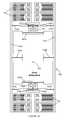
- FIG. 11shows a preferred embodiment wherein the movable part of the transducer faces outwards.
- FIG. 12shows a preferred embodiment wherein the movable part of the transducer faces inwards.
- the present inventionrelates to angular velocity sensors, and more particularly to the sensing frame of the angular velocity sensors.
- the following descriptionis presented to enable one of ordinary skill in the art to make and use the invention and is provided in the context of a patent application and its requirements.
- Various modifications to the preferred embodiment and the generic principles and features described hereinwill be readily apparent to those skilled in the art.
- the present inventionis not intended to be limited to the embodiment shown but is to be accorded the widest scope consistent with the principles and features described herein.
- the purpose of a system and method in accordance with the present inventionis to provide an improved sensing frame by reducing an effective mass of said sensing frame.
- the advantage of reduced inertiais that it improves sensitivity of the angular velocity sensor.
- Another advantage of a system and method in accordance with the present inventionis to provide the sensing frame which can be suspended to the sensing base at a minimum number of points. Minimizing the number of suspensions improves package sensitivity.
- Another advantage of a system and method in accordance with the present inventionis to provide a sensing frame having two rails constrained to move linearly in anti-phase fashion.
- Anti-phase sensingrejects linear acceleration sensitivity of the angular velocity sensor.
- the sensing framecan be used with X, Y or Z angular velocity sensor. Also, the sensing frame is easily adjustable in terms of its shape without altering its functionality. The sensing frame can be easily designed so that an angular velocity sensor fits easily onto the substrate with the neighboring MEMS devices. The sensing frame can be easily designed to enclose different drive systems. This substantially reduces the area of the sensor die without degrading performance of the angular velocity sensor.
- FIG. 1A and FIG. 1Bshow two embodiments of simplified illustrations of a sensing subassembly for detecting angular velocity as disclosed in U.S. Pat. No. 6,892,575, entitled “X-Y axis dual-mass tuning fork gyroscope with vertically integrated electronics and wafer-scale hermetic packaging,” and assigned to the assignee of the present application.
- sensing subassembly 10 and 10 ′comprises a drive subsystem 12 and 12 ′ and a sense subsystem 14 and 14 ′.
- the rigid sense frame 30is circular.
- the rigid sense frame 32is rectangular.
- the sense subsystem 14 and 14 ′is suspended to the base 18 at a plurality of anchoring points 16 A- 16 D through a plurality of anchoring flexures 20 A- 20 D.
- Drive subsystem 12 and 12 ′may be driven into oscillations based on the fundamental frequency of the drive subsystem 12 and 12 ′. Coriolis forces may generate a torque on the drive subsystem 12 and 12 ′ as depicted in FIG. 1A and FIG. 1B .
- Torqueis transferred to the sense subsystem 14 and 14 ′ through the coupling flexures 22 A- 22 B that connect drive subsystem 12 and 12 ′ and sense subsystems 14 and 14 ′ causing sense frame 30 and 32 to rotate.
- Motion of the sense subsystem 14 and 14 ′is proportional to the input angular velocity and can be sensed by appropriate transducer 24 .
- a sense subsystem 100 and 100 ′comprises anchoring flexures 110 A- 110 B and a frame further comprising rails 101 A- 101 B and guiding arms 102 A- 102 B.
- the rails 101 A and 101 B and guiding arms 102 A- 102 Bare flexibly coupled through the four frame flexures 103 A- 103 D.
- Both rails 101 A and 101 B and guiding arms 102 A- 102 Bare rigid when compared to stiffness of the frame flexures 103 A- 103 D and anchoring flexures 110 A- 110 D.
- the rails 101 A and 101 Bmay support transducer 130 .
- Drive subsystem 112 and the sense subsystem 114are flexibly connected through the coupling flexures 150 A and 150 B.
- the drive subsystem 112may be connected to the rails 101 A and 101 B as shown in FIG. 2A .
- the drive subsystem 112may be connected to the guiding arms 102 A and 102 B as depicted in FIG. 2B .
- the frame flexures 103 A- 103 Densure flexibility of the sensing frame.
- the anchoring flexures 110 A and 110 Bdefine pivot points for guiding arms 102 A- 102 B ensuring anti-phase motion of the rails 101 A and 101 B.
- the coupling flexures 150 A- 150 Bcouple the drive subsystem 112 to the sense subsystem 114 and transfer the Coriolis force to the sensing frame.
- FIG. 3Ashows the stiff sensing frame rotating about the axis passing through the center of gravity of the frame. The whole frame contributes to the effective moving mass.
- the flexible sensing frameis used as shown in FIG. 3B , two rails translate along the axis parallel to the plane contributing to the effective moving mass substantially similar as they did in said stiff frame case.
- two guiding armsrotate around their pivot points. Effectively, as each of two rotational axes pass through the center of gravity of each of two guiding arms, their effective moving mass is reduced by an order of magnitude. This substantially reduces the total effective mass of the sensing frame. Reduction in the mass of the sensing frame increases sensitivity of the angular velocity sensor.
- the advantage of the low-inertia flexible sensing frame on angular rate sensor sensitivityis described.
- the drive system, the generated Coriolis force and the sense frequencyare assumed to be the same.
- the sensitivity of the single-sense-mode angular velocity sensoris proportional to capacitance sensitivity over the combined inertia of the drive and sense subsystems
- I Sis the equivalent moment of inertia of the frame with transducers
- I Dis the equivalent moment of inertia of the drive subsystem.
- Corresponding rotational capacitance sensitivitiesare then given as
- Total inertia of the circular frameis given as
- I Sc4 ⁇ mR 2 + N ⁇ ⁇ ⁇ cf ⁇ L ⁇ ( R 2 + RL + L 2 3 ) , where ⁇ cf is mass of the electrode per unit length and ⁇ ef L is the mass of the electrode.
- the inertia of the flexible framemay be written as
- Total inertia of the flexible frame with electrodesis given as
- I Sf8 3 ⁇ mR 2 + N ⁇ ⁇ ⁇ cf ⁇ LR 2 .
- Sensitivity of both circular and flexible frame as a function of length of the electrodeis shown in FIG. 5 .
- the circular framereaches sensitivity maximum when influence of the moment of inertia becomes dominant over the gain in capacitance sensitivity.
- Length of the transducersis therefore related to the radius of the circular frame.
- Flexible frameallows adding longer transducers resulting in increased sensitivity.
- the design of the low inertia frameis therefore more flexible.
- the addition of more transducers to the circular framerequires increase in the frame radius.
- the transducerscan be added to the low-inertia frame just by extending the length of the rails.
- the low-inertia frameallows transducers to be attached to the frame parallel with respect to each other. This increases the area density of the capacitance sensitivity.
- the disclosed sensing framemay be used for sensing the angular velocity with input axis laying in-plane with the sensing frame or with input axis laying out-of-plane with respect to the sensing frame.
- FIG. 6depicts generic sensing subassembly 600 for detecting angular velocity around an in-plane and out-of-plane axes.
- Sensing subassemblycomprises a drive subsystem 602 and a sense subsystem 604 . Only proof masses 610 A-B, transmission mass 620 A- 620 B, and flexures 640 A- 640 B of the drive system are shown.
- Sense subsystem 604comprises the anchoring flexures 611 A-B and a frame further comprising a first and second rails 601 A and 601 B and first and second guiding arms 622 A and 622 B flexibly coupled through the four frame flexures 603 A- 603 D.
- Drive subsystem and the sense subsystemshare coupling flexures 650 A and 650 B.
- FIG. 7shows the way the drive subsystem from FIG. 6 may be driven into sustained oscillations at the frequency of the drive mode with an appropriate actuator.
- the drive subsystemmay be designed such that the proof masses move out-of-plane in anti-phase fashion as depicted in FIG. 7A . If the base 618 rotates around input axis X, generated Coriolis force is in plane. Coriolis forces act in opposite fashion on proof masses 610 A and 610 B resulting in Coriolis torque acting on the mass 620 .
- the input axismay be X axis. In another implementation, the input axis may be Y axis.
- the drive modemay comprise proof masses moving in anti-phase fashion in plane as depicted in the bottom part of FIG. 7B . If the base 618 rotates around input axis Z, the Coriolis force is generated in plane. Coriolis force acts in one direction on proof mass 610 A and in the opposite direction on proof mass 610 B resulting in Coriolis torque which eventually gets transferred on the mass 620 . The resulting Coriolis torque on mass 620 is normal to the X-Y plane regardless whether input axis is X, Y or Z.
- FIG. 8illustrates how the Coriolis torque acting on the drive subsystem 602 gets transferred to the sense subsystem 604 .
- Rails 601 A and 601 Bare flexibly connected to the center mass 620 through the pair of flexures 650 and are flexibly connected to the guiding arms 622 A and 622 B through the four frame flexures 603 A-D.
- the flexures 603 A-Dallow the frame to deform.
- the guiding armsare suspended to the base 618 through the anchoring flexures 611 A and 611 B.
- Torque acting on the mass 620causes opposite forces acting on rails 601 A and 601 B.
- Guiding arms 622 A- 622 Bcan only rotate causing the ring to deform. Motion of the rails is proportional to the input angular rate of rotation.
- the transducermay be attached to the rail so the motion of the rail can be detected.
- the sensing frameinherently rejects linear acceleration along the in-plane axis parallel to the rails.
- the sensing framehas two rails constrained to move in anti-phase fashion. This way it is ensured that there is no low frequency translational mode associated with motion of the sensing frame along the axis parallel to the rails. Consequently, any substantial motion caused by linear acceleration is mechanically rejected.
- the sensing frameneeds to be suspended to the base at minimum of two points. These points provide pivot points for the guiding arms. As shown in FIG. 9 , the drive subsystem may be suspended to the base 618 at two anchoring points as well. Two anchoring points may be shared by both drive and sense subsystems. This way, the whole angular velocity sensing subassembly relies on two anchoring point. Undesired effects of package stresses on mechanical structure is substantially reduced.
- the rails and guiding armsmay assume any shape as long as they are substantially stiff compared to flexures 603 A- 603 D and flexures 611 A- 611 B.
- the sense framecan be shaped as needed without decreasing the performance of the angular velocity sensor.
- the drive subsystemmay be optimized resulting in a particular shape. In order to minimize the sensor area, the optimized drive subsystem should be tightly enveloped with the sense frame. Circular, or even rigid rectangular frame may result in an unnecessary waste of area—first, the flexures suspending the sense subsystem to the substrate should be attached at a particular place at a particular angle, and second, the frame rotates so the attached transducers should lie along lines at angle such that their axial axes cross center of rotation.
- Both rails and guiding armscan be any shape as long as they remain substantially rigid.
- the flexibility of the shape of the framealso allows such angular velocity sensor to fit into sensing assembly with other devices such as the other angular velocity sensors or linear acceleration sensors.
- the transducerscan be attached to the rail in several different ways.
- FIG. 10illustrates several different embodiments with different frame shape and transducer accommodation.
- the anchoring flexures 710 A and 710 Bcomprise three beams each providing a pivot point for each of the guiding arms 702 A and 702 B.
- the anchoring flexures 710 A and 710 Balso increases translational stiffness as well as and out-of-plane rotational stiffness.
- the guiding arms 702 A and 702 Bare further connected to the rails 701 A and 701 B through the frame flexures 703 A- 703 D. There are total of four frame flexures 703 A-D comprising a single beam each.
- the frame flexures 703 A- 703 Dprovide necessary flexibility of the frame.
- the whole frame assemblyensures that any torque generated on the drive subsystem 760 gets transferred to the sense system 762 through coupling flexures 750 , and cause the rails 701 A and 701 B to move linearly in opposite directions.
- the drive subsystem 760is suspended to the base at the same anchor 720 A and 720 B as the guided arm. Joint anchoring reduces effects of package sensitivity by allowing the sense and drive system to move substantially similar as a result the stresses induced by the package.
- two railsare elongated so they can support capacitive transducers with its movable portion facing inwards. This way different configurations of the angular velocity sensors may be accommodated on multi-axis die.
- the teaching on frame and its flexuresis essentially similar to that related to FIG. 11 .
- the shape of the rails 701 A and 701 B, guiding arms 702 A and 702 B, frame flexures 703 A- 703 D and anchoring flexures 710 A and 710 Bcan differ from the shapes shown in FIG. 11 and FIG. 12 , and still provide the same benefit as described above.
Landscapes
- Physics & Mathematics (AREA)
- Engineering & Computer Science (AREA)
- General Physics & Mathematics (AREA)
- Radar, Positioning & Navigation (AREA)
- Remote Sensing (AREA)
- Gyroscopes (AREA)
Abstract
Description
where ∂C/∂θ is total effective rotational capacitance sensitivity, ISis the equivalent moment of inertia of the frame with transducers and IDis the equivalent moment of inertia of the drive subsystem.
for the circular frame, and
for the flexible frame.
where μcfis mass of the electrode per unit length and μefL is the mass of the electrode. On the other hand the inertia of the flexible frame may be written as
and the inertia of the attached fingers may be written as IEf=NμefLR2. Total inertia of the flexible frame with electrodes is given as
and sensitivity of the flexible frame
Claims (7)
Priority Applications (8)
| Application Number | Priority Date | Filing Date | Title |
|---|---|---|---|
| US12/210,045US8141424B2 (en) | 2008-09-12 | 2008-09-12 | Low inertia frame for detecting coriolis acceleration |
| US12/398,156US20090262074A1 (en) | 2007-01-05 | 2009-03-04 | Controlling and accessing content using motion processing on mobile devices |
| US12/485,823US8462109B2 (en) | 2007-01-05 | 2009-06-16 | Controlling and accessing content using motion processing on mobile devices |
| PCT/US2009/056744WO2010030951A1 (en) | 2008-09-12 | 2009-09-11 | Low inertia frame for detecting coriolis acceleration |
| US12/782,608US7907838B2 (en) | 2007-01-05 | 2010-05-18 | Motion sensing and processing on mobile devices |
| US13/046,623US8351773B2 (en) | 2007-01-05 | 2011-03-11 | Motion sensing and processing on mobile devices |
| US13/427,784US8539835B2 (en) | 2008-09-12 | 2012-03-22 | Low inertia frame for detecting coriolis acceleration |
| US13/910,485US9292102B2 (en) | 2007-01-05 | 2013-06-05 | Controlling and accessing content using motion processing on mobile devices |
Applications Claiming Priority (1)
| Application Number | Priority Date | Filing Date | Title |
|---|---|---|---|
| US12/210,045US8141424B2 (en) | 2008-09-12 | 2008-09-12 | Low inertia frame for detecting coriolis acceleration |
Related Parent Applications (2)
| Application Number | Title | Priority Date | Filing Date |
|---|---|---|---|
| US12/117,264Continuation-In-PartUS8508039B1 (en) | 2007-01-05 | 2008-05-08 | Wafer scale chip scale packaging of vertically integrated MEMS sensors with electronics |
| US12/236,757Continuation-In-PartUS20100071467A1 (en) | 2007-01-05 | 2008-09-24 | Integrated multiaxis motion sensor |
Related Child Applications (4)
| Application Number | Title | Priority Date | Filing Date |
|---|---|---|---|
| US12/106,921Continuation-In-PartUS8952832B2 (en) | 2007-01-05 | 2008-04-21 | Interfacing application programs and motion sensors of a device |
| US12/117,264Continuation-In-PartUS8508039B1 (en) | 2007-01-05 | 2008-05-08 | Wafer scale chip scale packaging of vertically integrated MEMS sensors with electronics |
| US12/236,757Continuation-In-PartUS20100071467A1 (en) | 2007-01-05 | 2008-09-24 | Integrated multiaxis motion sensor |
| US13/427,784ContinuationUS8539835B2 (en) | 2008-09-12 | 2012-03-22 | Low inertia frame for detecting coriolis acceleration |
Publications (2)
| Publication Number | Publication Date |
|---|---|
| US20100064805A1 US20100064805A1 (en) | 2010-03-18 |
| US8141424B2true US8141424B2 (en) | 2012-03-27 |
Family
ID=42005509
Family Applications (2)
| Application Number | Title | Priority Date | Filing Date |
|---|---|---|---|
| US12/210,045Active2030-03-01US8141424B2 (en) | 2007-01-05 | 2008-09-12 | Low inertia frame for detecting coriolis acceleration |
| US13/427,784ActiveUS8539835B2 (en) | 2008-09-12 | 2012-03-22 | Low inertia frame for detecting coriolis acceleration |
Family Applications After (1)
| Application Number | Title | Priority Date | Filing Date |
|---|---|---|---|
| US13/427,784ActiveUS8539835B2 (en) | 2008-09-12 | 2012-03-22 | Low inertia frame for detecting coriolis acceleration |
Country Status (2)
| Country | Link |
|---|---|
| US (2) | US8141424B2 (en) |
| WO (1) | WO2010030951A1 (en) |
Cited By (20)
| Publication number | Priority date | Publication date | Assignee | Title |
|---|---|---|---|---|
| US20100199762A1 (en)* | 2007-10-12 | 2010-08-12 | Daniel Christoph Meisel | Micromechanical device having a drive frame |
| US20120125101A1 (en)* | 2009-09-11 | 2012-05-24 | Invensense, Inc. | Mems device with improved spring system |
| US20120216612A1 (en)* | 2008-09-12 | 2012-08-30 | Invensense, Inc. | Low inertia frame for detecting coriolis acceleration |
| US20130068018A1 (en)* | 2011-09-16 | 2013-03-21 | Invensense, Inc. | Micromachined gyroscope including a guided mass system |
| US8462109B2 (en) | 2007-01-05 | 2013-06-11 | Invensense, Inc. | Controlling and accessing content using motion processing on mobile devices |
| US8508039B1 (en) | 2008-05-08 | 2013-08-13 | Invensense, Inc. | Wafer scale chip scale packaging of vertically integrated MEMS sensors with electronics |
| US20130233048A1 (en)* | 2011-09-16 | 2013-09-12 | Invensense, Inc. | Gyroscope self test by applying rotation on coriolis sense mass |
| US8952832B2 (en) | 2008-01-18 | 2015-02-10 | Invensense, Inc. | Interfacing application programs and motion sensors of a device |
| US8960002B2 (en) | 2007-12-10 | 2015-02-24 | Invensense, Inc. | Vertically integrated 3-axis MEMS angular accelerometer with integrated electronics |
| US8997564B2 (en) | 2007-07-06 | 2015-04-07 | Invensense, Inc. | Integrated motion processing unit (MPU) with MEMS inertial sensing and embedded digital electronics |
| US9008757B2 (en) | 2012-09-26 | 2015-04-14 | Stryker Corporation | Navigation system including optical and non-optical sensors |
| US9052194B2 (en) | 2009-09-11 | 2015-06-09 | Invensense, Inc. | Extension-mode angular velocity sensor |
| US9170107B2 (en)* | 2011-09-16 | 2015-10-27 | Invensense, Inc. | Micromachined gyroscope including a guided mass system |
| US9830043B2 (en) | 2012-08-21 | 2017-11-28 | Beijing Lenovo Software Ltd. | Processing method and processing device for displaying icon and electronic device |
| US9863769B2 (en) | 2011-09-16 | 2018-01-09 | Invensense, Inc. | MEMS sensor with decoupled drive system |
| US9909874B2 (en)* | 2013-04-11 | 2018-03-06 | Robert Bosch Gmbh | Rotation rate sensor |
| US9958271B2 (en) | 2014-01-21 | 2018-05-01 | Invensense, Inc. | Configuration to reduce non-linear motion |
| US10231337B2 (en) | 2014-12-16 | 2019-03-12 | Inertial Sense, Inc. | Folded printed circuit assemblies and related methods |
| US10914584B2 (en) | 2011-09-16 | 2021-02-09 | Invensense, Inc. | Drive and sense balanced, semi-coupled 3-axis gyroscope |
| US11415418B2 (en)* | 2017-04-04 | 2022-08-16 | Invensense, Inc. | Out-of-plane sensing gyroscope robust to external acceleration and rotation |
Families Citing this family (21)
| Publication number | Priority date | Publication date | Assignee | Title |
|---|---|---|---|---|
| US8427508B2 (en)* | 2009-06-25 | 2013-04-23 | Nokia Corporation | Method and apparatus for an augmented reality user interface |
| US8543917B2 (en) | 2009-12-11 | 2013-09-24 | Nokia Corporation | Method and apparatus for presenting a first-person world view of content |
| DE102010029634B4 (en)* | 2010-06-02 | 2024-04-11 | Robert Bosch Gmbh | Angular rate sensor |
| RU2611977C2 (en)* | 2011-05-09 | 2017-03-01 | Конинклейке Филипс Н.В. | Rotating object on screen |
| DE102012200132A1 (en)* | 2012-01-05 | 2013-07-11 | Robert Bosch Gmbh | Rotation rate sensor and method for operating a rotation rate sensor |
| JP5708535B2 (en) | 2012-03-13 | 2015-04-30 | 株式会社デンソー | Angular velocity sensor |
| FI125696B (en)* | 2013-09-11 | 2016-01-15 | Murata Manufacturing Co | Gyroscope construction and gyroscope with improved quadrature compensation |
| FI125695B (en)* | 2013-09-11 | 2016-01-15 | Murata Manufacturing Co | Improved gyroscope construction and gyroscope |
| EP3184961B1 (en)* | 2013-09-30 | 2021-01-06 | Invensense, Inc. | Micromachined gyroscope including a guided mass system |
| EP3237844B1 (en)* | 2014-12-26 | 2020-08-19 | Kivanc Azgin | Method for suppresion of g-sensitivity of mems gyroscope |
| FI127203B (en) | 2015-05-15 | 2018-01-31 | Murata Manufacturing Co | Vibrating micromechanical sensor for angular velocity |
| US20170185261A1 (en)* | 2015-12-28 | 2017-06-29 | Htc Corporation | Virtual reality device, method for virtual reality |
| CN105677039B (en)* | 2016-02-16 | 2020-06-09 | 北京博研智通科技有限公司 | Method and device for detecting driving state based on gesture and wearable device |
| ITUA20162172A1 (en)* | 2016-03-31 | 2017-10-01 | St Microelectronics Srl | ACCELEROMETRIC SENSOR MADE IN MEMS TECHNOLOGY WITH HIGH ACCURACY AND REDUCED SENSITIVITY TOWARDS TEMPERATURE AND AGING |
| CN106137209A (en)* | 2016-06-29 | 2016-11-23 | 广东威尔医院有限公司 | A kind of athletic posture detection method and Wearable device |
| DE102017011821B4 (en) | 2017-01-27 | 2020-12-31 | Fraunhofer-Gesellschaft zur Förderung der angewandten Forschung e.V. | MMS, MMS array, MEMS actuator and method for providing an MMS |
| JP6814892B2 (en) | 2017-01-27 | 2021-01-20 | フラウンホーファーゲゼルシャフト ツール フォルデルング デル アンゲヴァンテン フォルシユング エー.フアー. | Methods for Providing MMS, MMS Arrays, MEMS Actuators and MMS |
| DE102017201309B4 (en) | 2017-01-27 | 2020-06-04 | Fraunhofer-Gesellschaft zur Förderung der angewandten Forschung e.V. | MMS, MMS ARRAY, MEMS ACTUATOR AND METHOD FOR PROVIDING A MMS |
| JP7188311B2 (en)* | 2019-07-31 | 2022-12-13 | セイコーエプソン株式会社 | Gyro sensors, electronic devices, and mobile objects |
| IT201900017546A1 (en) | 2019-09-30 | 2021-03-30 | St Microelectronics Srl | WATER RESISTANT MEMS BUTTON DEVICE, INPUT DEVICE INCLUDING MEMS BUTTON DEVICE AND ELECTRONIC DEVICE |
| TWI872681B (en)* | 2022-09-02 | 2025-02-11 | 昇佳電子股份有限公司 | Inertial sensor |
Citations (185)
| Publication number | Priority date | Publication date | Assignee | Title |
|---|---|---|---|---|
| US4510802A (en)* | 1983-09-02 | 1985-04-16 | Sundstrand Data Control, Inc. | Angular rate sensor utilizing two vibrating accelerometers secured to a parallelogram linkage |
| US4601206A (en) | 1983-09-16 | 1986-07-22 | Ferranti Plc | Accelerometer system |
| US4736629A (en) | 1985-12-20 | 1988-04-12 | Silicon Designs, Inc. | Micro-miniature accelerometer |
| US4783742A (en) | 1986-12-31 | 1988-11-08 | Sundstrand Data Control, Inc. | Apparatus and method for gravity correction in borehole survey systems |
| US4841773A (en) | 1987-05-01 | 1989-06-27 | Litton Systems, Inc. | Miniature inertial measurement unit |
| US5251484A (en) | 1992-04-03 | 1993-10-12 | Hewlett-Packard Company | Rotational accelerometer |
| US5349858A (en) | 1991-01-29 | 1994-09-27 | Canon Kabushiki Kaisha | Angular acceleration sensor |
| US5359893A (en) | 1991-12-19 | 1994-11-01 | Motorola, Inc. | Multi-axes gyroscope |
| US5367631A (en) | 1992-04-14 | 1994-11-22 | Apple Computer, Inc. | Cursor control device with programmable preset cursor positions |
| US5415040A (en) | 1993-03-03 | 1995-05-16 | Zexel Corporation | Acceleration sensor |
| US5433110A (en) | 1992-10-29 | 1995-07-18 | Sextant Avionique | Detector having selectable multiple axes of sensitivity |
| US5440326A (en) | 1990-03-21 | 1995-08-08 | Gyration, Inc. | Gyroscopic pointer |
| US5444639A (en) | 1993-09-07 | 1995-08-22 | Rockwell International Corporation | Angular rate sensing system and method, with digital synthesizer and variable-frequency oscillator |
| EP0429391B1 (en) | 1989-11-06 | 1995-08-23 | International Business Machines Corporation | Three-dimensional computer input device |
| US5511419A (en) | 1991-12-19 | 1996-04-30 | Motorola | Rotational vibration gyroscope |
| US5541860A (en) | 1988-06-22 | 1996-07-30 | Fujitsu Limited | Small size apparatus for measuring and recording acceleration |
| US5574221A (en) | 1993-10-29 | 1996-11-12 | Samsung Electro-Mechanics Co., Ltd. | Angular acceleration sensor |
| US5629988A (en) | 1993-06-04 | 1997-05-13 | David Sarnoff Research Center, Inc. | System and method for electronic image stabilization |
| US5635639A (en) | 1991-09-11 | 1997-06-03 | The Charles Stark Draper Laboratory, Inc. | Micromechanical tuning fork angular rate sensor |
| US5635638A (en) | 1995-06-06 | 1997-06-03 | Analog Devices, Inc. | Coupling for multiple masses in a micromachined device |
| US5698784A (en) | 1996-01-24 | 1997-12-16 | Gyration, Inc. | Vibratory rate gyroscope and methods of assembly and operation |
| US5703293A (en) | 1995-05-27 | 1997-12-30 | Robert Bosch Gmbh | Rotational rate sensor with two acceleration sensors |
| US5703623A (en) | 1996-01-24 | 1997-12-30 | Hall; Malcolm G. | Smart orientation sensing circuit for remote control |
| US5734373A (en) | 1993-07-16 | 1998-03-31 | Immersion Human Interface Corporation | Method and apparatus for controlling force feedback interface systems utilizing a host computer |
| US5780740A (en) | 1995-10-27 | 1998-07-14 | Samsung Electronics Co., Ltd. | Vibratory structure, method for controlling natural frequency thereof, and actuator, sensor, accelerator, gyroscope and gyroscope natural frequency controlling method using vibratory structure |
| US5825350A (en) | 1996-03-13 | 1998-10-20 | Gyration, Inc. | Electronic pointing apparatus and method |
| US5895850A (en) | 1994-04-23 | 1999-04-20 | Robert Bosch Gmbh | Micromechanical resonator of a vibration gyrometer |
| US5955668A (en) | 1997-01-28 | 1999-09-21 | Irvine Sensors Corporation | Multi-element micro gyro |
| US5992233A (en) | 1996-05-31 | 1999-11-30 | The Regents Of The University Of California | Micromachined Z-axis vibratory rate gyroscope |
| US5996409A (en) | 1997-05-10 | 1999-12-07 | Robert Bosch Gmbh | Acceleration sensing device |
| US6122961A (en) | 1997-09-02 | 2000-09-26 | Analog Devices, Inc. | Micromachined gyros |
| US6134961A (en) | 1998-06-24 | 2000-10-24 | Aisin Seiki Kabushiki Kaisha | Angular velocity sensor |
| US6158280A (en) | 1997-12-22 | 2000-12-12 | Kabushiki Kaisha Toyota Chuo Kenkyusho | Detector for detecting angular velocities about perpendicular axes |
| US6168965B1 (en) | 1999-08-12 | 2001-01-02 | Tower Semiconductor Ltd. | Method for making backside illuminated image sensor |
| US6189381B1 (en) | 1999-04-26 | 2001-02-20 | Sitek, Inc. | Angular rate sensor made from a structural wafer of single crystal silicon |
| US6230564B1 (en) | 1998-02-19 | 2001-05-15 | Akebono Brake Industry Co., Ltd. | Semiconductor acceleration sensor and its self-diagnosing method |
| US6250157B1 (en) | 1998-06-22 | 2001-06-26 | Aisin Seiki Kabushiki Kaisha | Angular rate sensor |
| US6250156B1 (en) | 1996-05-31 | 2001-06-26 | The Regents Of The University Of California | Dual-mass micromachined vibratory rate gyroscope |
| US6269254B1 (en) | 1998-09-28 | 2001-07-31 | Motorola, Inc. | Radio communications device and method with API between user application program and telephony program and method |
| US6279043B1 (en) | 1998-05-01 | 2001-08-21 | Apple Computer, Inc. | Method and system for script access to API functionality |
| US6292170B1 (en) | 1997-04-25 | 2001-09-18 | Immersion Corporation | Designing compound force sensations for computer applications |
| US6343349B1 (en) | 1997-11-14 | 2002-01-29 | Immersion Corporation | Memory caching for force feedback effects |
| US20020027296A1 (en) | 1999-12-10 | 2002-03-07 | Badehi Avner Pierre | Methods for producing packaged integrated circuit devices & packaged integrated circuit devices produced thereby |
| US6374255B1 (en) | 1996-05-21 | 2002-04-16 | Immersion Corporation | Haptic authoring |
| US6370937B2 (en) | 2000-03-17 | 2002-04-16 | Microsensors, Inc. | Method of canceling quadrature error in an angular rate sensor |
| US6386033B1 (en) | 1998-07-10 | 2002-05-14 | Murata Manufacturing Co., | Angular velocity sensor |
| US6391673B1 (en) | 1999-11-04 | 2002-05-21 | Samsung Electronics Co., Ltd. | Method of fabricating micro electro mechanical system structure which can be vacuum-packed at wafer level |
| US6393914B1 (en) | 2001-02-13 | 2002-05-28 | Delphi Technologies, Inc. | Angular accelerometer |
| US6424356B2 (en) | 1999-05-05 | 2002-07-23 | Immersion Corporation | Command of force sensations in a forceback system using force effect suites |
| US6429895B1 (en) | 1996-12-27 | 2002-08-06 | Canon Kabushiki Kaisha | Image sensing apparatus and method capable of merging function for obtaining high-precision image by synthesizing images and image stabilization function |
| US6430998B2 (en) | 1999-12-03 | 2002-08-13 | Murata Manufacturing Co., Ltd. | Resonant element |
| US6480320B2 (en) | 2001-02-07 | 2002-11-12 | Transparent Optical, Inc. | Microelectromechanical mirror and mirror array |
| US6481283B1 (en) | 1999-04-05 | 2002-11-19 | Milli Sensor Systems & Actuators, Inc. | Coriolis oscillating gyroscopic instrument |
| US6481285B1 (en) | 1999-04-21 | 2002-11-19 | Andrei M. Shkel | Micro-machined angle-measuring gyroscope |
| US6487369B1 (en) | 1999-04-26 | 2002-11-26 | Olympus Optical Co., Ltd. | Camera with blur reducing function |
| US6494096B2 (en) | 2000-03-16 | 2002-12-17 | Denso Corporation | Semiconductor physical quantity sensor |
| US20020189351A1 (en) | 2001-06-14 | 2002-12-19 | Reeds John W. | Angular rate sensor having a sense element constrained to motion about a single axis and flexibly attached to a rotary drive mass |
| US6508122B1 (en) | 1999-09-16 | 2003-01-21 | American Gnc Corporation | Microelectromechanical system for measuring angular rate |
| US6508125B2 (en) | 2000-09-07 | 2003-01-21 | Mitsubishi Denki Kabushiki Kaisha | Electrostatic capacitance type acceleration sensor, electrostatic capacitance type angular acceleration sensor and electrostatic actuator |
| US6513380B2 (en) | 2001-06-19 | 2003-02-04 | Microsensors, Inc. | MEMS sensor with single central anchor and motion-limiting connection geometry |
| US6520017B1 (en) | 1999-08-12 | 2003-02-18 | Robert Bosch Gmbh | Micromechanical spin angular acceleration sensor |
| US6573883B1 (en) | 1998-06-24 | 2003-06-03 | Hewlett Packard Development Company, L.P. | Method and apparatus for controlling a computing device with gestures |
| US20030159511A1 (en) | 2002-02-28 | 2003-08-28 | Zarabadi Seyed R. | Angular accelerometer having balanced inertia mass |
| US6636521B1 (en) | 1998-12-18 | 2003-10-21 | Lucent Technologies Inc. | Flexible runtime configurable application program interface (API) that is command independent and reusable |
| US6646289B1 (en) | 1998-02-06 | 2003-11-11 | Shellcase Ltd. | Integrated circuit device |
| US6668614B2 (en) | 2001-10-16 | 2003-12-30 | Denso Corporation | Capacitive type physical quantity detecting sensor for detecting physical quantity along plural axes |
| US20040016995A1 (en) | 2002-07-25 | 2004-01-29 | Kuo Shun Meen | MEMS control chip integration |
| US20040066981A1 (en) | 2001-04-09 | 2004-04-08 | Mingjing Li | Hierarchical scheme for blur detection in digital image using wavelet transform |
| US6720994B1 (en) | 1999-10-28 | 2004-04-13 | Raytheon Company | System and method for electronic stabilization for second generation forward looking infrared systems |
| US6725719B2 (en) | 2002-04-17 | 2004-04-27 | Milli Sensor Systems And Actuators, Inc. | MEMS-integrated inertial measurement units on a common substrate |
| US6758093B2 (en) | 1999-07-08 | 2004-07-06 | California Institute Of Technology | Microgyroscope with integrated vibratory element |
| US20040160525A1 (en) | 2003-02-14 | 2004-08-19 | Minolta Co., Ltd. | Image processing apparatus and method |
| US20040179108A1 (en) | 2003-03-11 | 2004-09-16 | Sightic Vista Ltd. | Adaptive low-light image processing |
| US6794272B2 (en) | 2001-10-26 | 2004-09-21 | Ifire Technologies, Inc. | Wafer thinning using magnetic mirror plasma |
| US6796178B2 (en) | 2002-02-08 | 2004-09-28 | Samsung Electronics Co., Ltd. | Rotation-type decoupled MEMS gyroscope |
| US6823733B2 (en)* | 2002-11-04 | 2004-11-30 | Matsushita Electric Industrial Co., Ltd. | Z-axis vibration gyroscope |
| US6834249B2 (en) | 2001-03-29 | 2004-12-21 | Arraycomm, Inc. | Method and apparatus for controlling a computing system |
| US6843127B1 (en)* | 2003-07-30 | 2005-01-18 | Motorola, Inc. | Flexible vibratory micro-electromechanical device |
| US6845669B2 (en) | 2001-05-02 | 2005-01-25 | The Regents Of The University Of California | Non-resonant four degrees-of-freedom micromachined gyroscope |
| US6848304B2 (en) | 2003-04-28 | 2005-02-01 | Analog Devices, Inc. | Six degree-of-freedom micro-machined multi-sensor |
| US6859751B2 (en) | 2001-12-17 | 2005-02-22 | Milli Sensor Systems & Actuators, Inc. | Planar inertial measurement units based on gyros and accelerometers with a common structure |
| US6860150B2 (en) | 2002-10-12 | 2005-03-01 | Samsung Electro-Mechanics Co., Ltd. | Microgyroscope tunable for translational acceleration |
| US20050066728A1 (en) | 2003-09-25 | 2005-03-31 | Kionix, Inc. | Z-axis angular rate micro electro-mechanical systems (MEMS) sensor |
| WO2005043079A2 (en) | 2003-10-20 | 2005-05-12 | Invensense Inc. | X-y axis dual-mass tuning fork gyroscope with vertically integrated electronics and wafer-scale hermetic packaging |
| US20050110778A1 (en) | 2000-12-06 | 2005-05-26 | Mourad Ben Ayed | Wireless handwriting input device using grafitis and bluetooth |
| US6915693B2 (en)* | 2001-12-14 | 2005-07-12 | Samsung Electronics Co., Ltd. | MEMS gyroscope having mass vibrating vertically on substrate |
| US6918297B2 (en) | 2003-02-28 | 2005-07-19 | Honeywell International, Inc. | Miniature 3-dimensional package for MEMS sensors |
| US6918298B2 (en) | 2002-12-24 | 2005-07-19 | Samsung Electro-Mechanics Co., Ltd. | Horizontal and tuning fork vibratory microgyroscope |
| US6939473B2 (en) | 2003-10-20 | 2005-09-06 | Invensense Inc. | Method of making an X-Y axis dual-mass tuning fork gyroscope with vertically integrated electronics and wafer-scale hermetic packaging |
| US6938484B2 (en) | 2003-01-16 | 2005-09-06 | The Regents Of The University Of Michigan | Micromachined capacitive lateral accelerometer device and monolithic, three-axis accelerometer having same |
| US20050212751A1 (en) | 2004-03-23 | 2005-09-29 | Marvit David L | Customizable gesture mappings for motion controlled handheld devices |
| US6952965B2 (en)* | 2002-12-24 | 2005-10-11 | Samsung Electronics Co., Ltd. | Vertical MEMS gyroscope by horizontal driving |
| US6955086B2 (en) | 2001-11-19 | 2005-10-18 | Mitsubishi Denki Kabushiki Kaisha | Acceleration sensor |
| US6963345B2 (en) | 2000-03-07 | 2005-11-08 | Microsoft Corporation | API communications for vertex and pixel shaders |
| US6972480B2 (en) | 2003-06-16 | 2005-12-06 | Shellcase Ltd. | Methods and apparatus for packaging integrated circuit devices |
| US6981416B2 (en) | 2003-11-21 | 2006-01-03 | Chung-Shan Institute Of Science And Technology | Multi-axis solid state accelerometer |
| US20060017837A1 (en) | 2004-07-22 | 2006-01-26 | Sightic Vista Ltd. | Enhancing digital photography |
| US20060032308A1 (en) | 2004-08-16 | 2006-02-16 | Cenk Acar | Torsional nonresonant z-axis micromachined gyroscope with non-resonant actuation to measure the angular rotation of an object |
| US20060033823A1 (en) | 2002-09-25 | 2006-02-16 | Keisuke Okamura | Imaging device, imaging device image output method, and computer program |
| US7004025B2 (en) | 2000-06-23 | 2006-02-28 | Murata Manufacturing Co., Ltd. | Composite sensor device and method of producing the same |
| US20060061545A1 (en) | 2004-04-02 | 2006-03-23 | Media Lab Europe Limited ( In Voluntary Liquidation). | Motion-activated control with haptic feedback |
| US7028546B2 (en) | 2003-10-21 | 2006-04-18 | Instrumented Sensor Technology, Inc. | Data recorder |
| US7028547B2 (en) | 2001-03-06 | 2006-04-18 | Microstone Co., Ltd. | Body motion detector |
| WO2006043890A1 (en) | 2004-10-20 | 2006-04-27 | Imego Ab | Sensor device |
| US7036372B2 (en) | 2003-09-25 | 2006-05-02 | Kionix, Inc. | Z-axis angular rate sensor |
| US7040163B2 (en) | 2002-08-12 | 2006-05-09 | The Boeing Company | Isolated planar gyroscope with internal radial sensing and actuation |
| US7040922B2 (en) | 2003-06-05 | 2006-05-09 | Analog Devices, Inc. | Multi-surface mounting member and electronic device |
| US20060115297A1 (en) | 2004-11-29 | 2006-06-01 | Fuji Photo Film Co., Ltd. | Imaging device and imaging method |
| US7057645B1 (en) | 1999-02-02 | 2006-06-06 | Minolta Co., Ltd. | Camera system that compensates low luminance by composing multiple object images |
| US20060119710A1 (en) | 2002-06-21 | 2006-06-08 | Moshe Ben-Ezra | Systems and methods for de-blurring motion blurred images |
| US20060139327A1 (en) | 2002-10-15 | 2006-06-29 | Sony Corporation/Sony Electronics | Method and system for controlling a display device |
| US7077007B2 (en) | 2001-02-14 | 2006-07-18 | Delphi Technologies, Inc. | Deep reactive ion etching process and microelectromechanical devices formed thereby |
| US20060164385A1 (en) | 2003-05-01 | 2006-07-27 | Smith Gregory C | Multimedia user interface |
| US20060164382A1 (en) | 2005-01-25 | 2006-07-27 | Technology Licensing Company, Inc. | Image manipulation in response to a movement of a display |
| US20060187308A1 (en) | 2005-02-23 | 2006-08-24 | Lim Suk H | Method for deblurring an image |
| US20060185502A1 (en) | 2000-01-11 | 2006-08-24 | Yamaha Corporation | Apparatus and method for detecting performer's motion to interactively control performance of music or the like |
| US7104129B2 (en) | 2004-02-02 | 2006-09-12 | Invensense Inc. | Vertically integrated MEMS structure with electronics in a hermetically sealed cavity |
| US7121141B2 (en) | 2005-01-28 | 2006-10-17 | Freescale Semiconductor, Inc. | Z-axis accelerometer with at least two gap sizes and travel stops disposed outside an active capacitor area |
| US20060251410A1 (en) | 2005-05-05 | 2006-11-09 | Trutna William R Jr | Imaging device employing optical motion sensor as gyroscope |
| US7154477B1 (en) | 2003-09-03 | 2006-12-26 | Apple Computer, Inc. | Hybrid low power computer mouse |
| US7155975B2 (en) | 2001-06-25 | 2007-01-02 | Matsushita Electric Industrial Co., Ltd. | Composite sensor for detecting angular velocity and acceleration |
| US7158118B2 (en) | 2004-04-30 | 2007-01-02 | Hillcrest Laboratories, Inc. | 3D pointing devices with orientation compensation and improved usability |
| US7159442B1 (en) | 2005-01-06 | 2007-01-09 | The United States Of America As Represented By The Secretary Of The Navy | MEMS multi-directional shock sensor |
| US7168317B2 (en) | 2003-11-04 | 2007-01-30 | Chung-Shan Institute Of Science And Technology | Planar 3-axis inertial measurement unit |
| US20070035630A1 (en) | 2005-08-12 | 2007-02-15 | Volker Lindenstruth | Method and apparatus for electronically stabilizing digital images |
| US7180500B2 (en) | 2004-03-23 | 2007-02-20 | Fujitsu Limited | User definable gestures for motion controlled handheld devices |
| US20070063985A1 (en) | 2000-03-22 | 2007-03-22 | Semiconductor Energy Laboratory Co., Ltd. | Electronic Device |
| US7196404B2 (en) | 2004-05-20 | 2007-03-27 | Analog Devices, Inc. | Motion detector and method of producing the same |
| US7210351B2 (en) | 2004-06-10 | 2007-05-01 | Chung Shan Institute Of Science And Technology | Micro accelerometer |
| US20070113207A1 (en) | 2005-11-16 | 2007-05-17 | Hillcrest Laboratories, Inc. | Methods and systems for gesture classification in 3D pointing devices |
| US7222533B2 (en) | 2005-06-06 | 2007-05-29 | Bei Technologies, Inc. | Torsional rate sensor with momentum balance and mode decoupling |
| US7236156B2 (en) | 2004-04-30 | 2007-06-26 | Hillcrest Laboratories, Inc. | Methods and devices for identifying users based on tremor |
| US20070146325A1 (en) | 2005-12-27 | 2007-06-28 | Timothy Poston | Computer input device enabling three degrees of freedom and related input and feedback methods |
| US7237437B1 (en) | 2005-10-27 | 2007-07-03 | Honeywell International Inc. | MEMS sensor systems and methods |
| US7239301B2 (en) | 2004-04-30 | 2007-07-03 | Hillcrest Laboratories, Inc. | 3D pointing devices and methods |
| US7240552B2 (en) | 2005-06-06 | 2007-07-10 | Bei Technologies, Inc. | Torsional rate sensor with momentum balance and mode decoupling |
| US7243561B2 (en) | 2003-08-26 | 2007-07-17 | Matsushita Electric Works, Ltd. | Sensor device |
| US20070167199A1 (en) | 2006-01-04 | 2007-07-19 | Samsung Electronics Co., Ltd. | Apparatus and method for sensing folder rotation status in a portable terminal |
| US7247246B2 (en) | 2003-10-20 | 2007-07-24 | Atmel Corporation | Vertical integration of a MEMS structure with electronics in a hermetically sealed cavity |
| US20070176898A1 (en) | 2006-02-01 | 2007-08-02 | Memsic, Inc. | Air-writing and motion sensing input for portable devices |
| US7258011B2 (en) | 2005-11-21 | 2007-08-21 | Invensense Inc. | Multiple axis accelerometer |
| US7258008B2 (en)* | 2004-12-29 | 2007-08-21 | Stmicroelectronics S.R.L. | Micro-electro-mechanical gyroscope having electrically insulated regions |
| US7260789B2 (en) | 2004-02-23 | 2007-08-21 | Hillcrest Laboratories, Inc. | Method of real-time incremental zooming |
| US7284430B2 (en) | 2005-08-15 | 2007-10-23 | The Regents Of The University Of California | Robust micromachined gyroscopes with two degrees of freedom sense-mode oscillator |
| US7289898B2 (en) | 2005-05-13 | 2007-10-30 | Samsung Electronics Co., Ltd. | Apparatus and method for measuring speed of a moving object |
| US7290435B2 (en) | 2006-02-06 | 2007-11-06 | Invensense Inc. | Method and apparatus for electronic cancellation of quadrature error |
| US7299695B2 (en) | 2002-02-25 | 2007-11-27 | Fujitsu Media Devices Limited | Acceleration sensor |
| US20080009348A1 (en) | 2002-07-31 | 2008-01-10 | Sony Computer Entertainment Inc. | Combiner method for altering game gearing |
| US7325454B2 (en) | 2004-09-30 | 2008-02-05 | Honda Motor Co., Ltd. | Acceleration/angular velocity sensor unit |
| US7333087B2 (en) | 2004-01-27 | 2008-02-19 | Samsung Electronics Co., Ltd. | Method of adjusting pointing position during click operation and 3D input device using the same |
| US7331212B2 (en) | 2006-01-09 | 2008-02-19 | Delphi Technologies, Inc. | Sensor module |
| US7352567B2 (en) | 2005-08-09 | 2008-04-01 | Apple Inc. | Methods and apparatuses for docking a portable electronic device that has a planar like configuration and that operates in multiple orientations |
| US20080088602A1 (en) | 2005-03-04 | 2008-04-17 | Apple Inc. | Multi-functional hand-held device |
| US20080098315A1 (en) | 2006-10-18 | 2008-04-24 | Dao-Liang Chou | Executing an operation associated with a region proximate a graphic element on a surface |
| US7377167B2 (en) | 2004-02-27 | 2008-05-27 | The Regents Of The University Of California | Nonresonant micromachined gyroscopes with structural mode-decoupling |
| US7386806B2 (en) | 2005-01-05 | 2008-06-10 | Hillcrest Laboratories, Inc. | Scaling and layout methods and systems for handling one-to-many objects |
| US20080134784A1 (en) | 2006-12-12 | 2008-06-12 | Industrial Technology Research Institute | Inertial input apparatus with six-axial detection ability and the operating method thereof |
| US7395181B2 (en) | 1998-04-17 | 2008-07-01 | Massachusetts Institute Of Technology | Motion tracking system |
| US20080204566A1 (en) | 2005-09-09 | 2008-08-28 | Canon Kabushiki Kaisha | Image pickup apparatus |
| US7424213B2 (en) | 2004-09-17 | 2008-09-09 | Canon Kabushiki Kaisha | Camera system, image capturing apparatus, and a method of an image capturing apparatus |
| US7437931B2 (en) | 2006-07-24 | 2008-10-21 | Honeywell International Inc. | Medical application for no-motion sensor |
| US7442570B2 (en) | 2005-03-18 | 2008-10-28 | Invensence Inc. | Method of fabrication of a AL/GE bonding in a wafer packaging environment and a product produced therefrom |
| US7454971B2 (en)* | 2004-12-31 | 2008-11-25 | Vti Technologies Oy | Oscillating micro-mechanical sensor of angular velocity |
| US7458263B2 (en) | 2003-10-20 | 2008-12-02 | Invensense Inc. | Method of making an X-Y axis dual-mass tuning fork gyroscope with vertically integrated electronics and wafer-scale hermetic packaging |
| US20080314147A1 (en) | 2007-06-21 | 2008-12-25 | Invensense Inc. | Vertically integrated 3-axis mems accelerometer with electronics |
| US20090005975A1 (en) | 2007-06-28 | 2009-01-01 | Apple Inc. | Adaptive Mobile Device Navigation |
| US20090005986A1 (en) | 2007-06-26 | 2009-01-01 | Honeywell International Inc. | Low power inertial navigation processing |
| US20090043504A1 (en) | 2007-05-31 | 2009-02-12 | Amrit Bandyopadhyay | System and method for locating, tracking, and/or monitoring the status of personnel and/or assets both indoors and outdoors |
| US7508384B2 (en) | 2005-06-08 | 2009-03-24 | Daka Research Inc. | Writing system |
| US20090088204A1 (en) | 2007-10-01 | 2009-04-02 | Apple Inc. | Movement-based interfaces for personal media device |
| US7522947B2 (en) | 2004-11-16 | 2009-04-21 | Canon Kabushiki Kaisha | Image display apparatus, display control method for the same, program, and storage medium |
| US7533569B2 (en) | 2006-03-15 | 2009-05-19 | Qualcomm, Incorporated | Sensor-based orientation system |
| US7549335B2 (en) | 2005-04-22 | 2009-06-23 | Hitachi Metals, Ltd. | Free fall detection device |
| US7552636B2 (en) | 2007-04-17 | 2009-06-30 | Ut-Battelle, Llc | Electron/hole transport-based NEMS gyro and devices using the same |
| US7617728B2 (en) | 2006-05-17 | 2009-11-17 | Donato Cardarelli | Tuning fork gyroscope |
| US7621183B2 (en) | 2005-11-18 | 2009-11-24 | Invensense Inc. | X-Y axis dual-mass tuning fork gyroscope with vertically integrated electronics and wafer-scale hermetic packaging |
| US20090326851A1 (en) | 2006-04-13 | 2009-12-31 | Jaymart Sensors, Llc | Miniaturized Inertial Measurement Unit and Associated Methods |
| US20100013814A1 (en) | 2006-05-05 | 2010-01-21 | Benq Mobile Gmbh & Co. Ohg | LCD Circuit and A Method For Triggering At Least One Pixel Of A Liquid Crystal Display |
| US7677099B2 (en)* | 2007-11-05 | 2010-03-16 | Invensense Inc. | Integrated microelectromechanical systems (MEMS) vibrating mass Z-axis rate sensor |
| US7677100B2 (en) | 2007-09-19 | 2010-03-16 | Murata Manufacturing Co., Ltd | Composite sensor and acceleration sensor |
| US7765869B2 (en) | 2007-07-19 | 2010-08-03 | Konkuk University Industrial Cooperation Corp. | Combined accelerometer and gyroscope system |
| US7779689B2 (en) | 2007-02-21 | 2010-08-24 | Freescale Semiconductor, Inc. | Multiple axis transducer with multiple sensing range capability |
| US7783392B2 (en) | 2005-10-13 | 2010-08-24 | Toyota Jidosha Kabushiki Kaisha | Traveling apparatus and method of controlling the same |
| US7784344B2 (en) | 2007-11-29 | 2010-08-31 | Honeywell International Inc. | Integrated MEMS 3D multi-sensor |
| US7907838B2 (en) | 2007-01-05 | 2011-03-15 | Invensense, Inc. | Motion sensing and processing on mobile devices |
Family Cites Families (41)
| Publication number | Priority date | Publication date | Assignee | Title |
|---|---|---|---|---|
| US4303978A (en) | 1980-04-18 | 1981-12-01 | The Boeing Company | Integrated-strapdown-air-data sensor system |
| US5313835A (en) | 1991-12-19 | 1994-05-24 | Motorola, Inc. | Integrated monolithic gyroscopes/accelerometers with logic circuits |
| US6192756B1 (en)* | 1998-02-12 | 2001-02-27 | Ngk Insulators, Ltd. | Vibrators vibratory gyroscopes a method of detecting a turning angular rate and a linear accelerometer |
| US6647352B1 (en) | 1998-06-05 | 2003-11-11 | Crossbow Technology | Dynamic attitude measurement method and apparatus |
| JP2001174283A (en) | 1999-12-15 | 2001-06-29 | Daikin Ind Ltd | Rotary flying object attitude measurement device |
| US6729176B2 (en) | 2000-03-31 | 2004-05-04 | Magellan Dis, Inc. | Calibration of orthogonal sensor suite |
| US7688306B2 (en) | 2000-10-02 | 2010-03-30 | Apple Inc. | Methods and apparatuses for operating a portable device based on an accelerometer |
| EP1337840A1 (en) | 2000-10-27 | 2003-08-27 | The Procter & Gamble Company | An improved consumer product kit, and a method of use therefor |
| US7253079B2 (en) | 2002-05-09 | 2007-08-07 | The Charles Stark Draper Laboratory, Inc. | Coplanar mounting member for a MEM sensor |
| US7335971B2 (en) | 2003-03-31 | 2008-02-26 | Robert Bosch Gmbh | Method for protecting encapsulated sensor structures using stack packaging |
| US6979872B2 (en) | 2003-05-13 | 2005-12-27 | Rockwell Scientific Licensing, Llc | Modules integrating MEMS devices with pre-processed electronic circuitry, and methods for fabricating such modules |
| DE10343967A1 (en) | 2003-09-19 | 2005-04-28 | Icido Ges Fuer Innovative Info | Spatial user interface for controlling a virtual reality graphics system by means of a function selection |
| JP4433747B2 (en)* | 2003-09-29 | 2010-03-17 | 株式会社村田製作所 | Angular velocity detector |
| US20060074558A1 (en) | 2003-11-26 | 2006-04-06 | Williamson Walton R | Fault-tolerant system, apparatus and method |
| US7043985B2 (en)* | 2004-01-13 | 2006-05-16 | Georgia Tech Research Corporation | High-resolution in-plane tuning fork gyroscope and methods of fabrication |
| JP4859347B2 (en) | 2004-02-18 | 2012-01-25 | セイコーエプソン株式会社 | Vibrating gyroscope |
| JP2005283428A (en) | 2004-03-30 | 2005-10-13 | Denso Corp | Dynamic quantity sensor unit |
| KR100622372B1 (en) | 2004-06-01 | 2006-09-19 | 삼성전자주식회사 | Gyro sensor comprising a plurality of configuration units and a manufacturing method thereof |
| FR2876180B1 (en)* | 2004-10-06 | 2006-12-08 | Commissariat Energie Atomique | RESONATOR WITH OSCILLATING MASSES. |
| DE102004056416A1 (en) | 2004-11-23 | 2006-05-24 | Robert Bosch Gmbh | Accelerometer in a controller |
| US7219033B2 (en) | 2005-02-15 | 2007-05-15 | Magneto Inertial Sensing Technology, Inc. | Single/multiple axes six degrees of freedom (6 DOF) inertial motion capture system with initial orientation determination capability |
| JP4670427B2 (en) | 2005-03-28 | 2011-04-13 | パナソニック電工株式会社 | Semiconductor sensor and manufacturing method thereof |
| US8339363B2 (en) | 2005-05-13 | 2012-12-25 | Robert Bosch Gmbh | Sensor-initiated exchange of information between devices |
| US7562573B2 (en) | 2005-07-21 | 2009-07-21 | Evigia Systems, Inc. | Integrated sensor and circuitry and process therefor |
| GB0515796D0 (en) | 2005-07-30 | 2005-09-07 | Mccarthy Peter | A motion capture and identification device |
| US7275008B2 (en) | 2005-09-02 | 2007-09-25 | Nokia Corporation | Calibration of 3D field sensors |
| US7683775B2 (en) | 2005-11-30 | 2010-03-23 | Frank Levinson | Low power pulse modulation communication in mesh networks with modular sensors |
| JP4839826B2 (en) | 2005-12-22 | 2011-12-21 | パナソニック電工株式会社 | Sensor module |
| US8113050B2 (en) | 2006-01-25 | 2012-02-14 | The Regents Of The University Of California | Robust six degree-of-freedom micromachined gyroscope with anti-phase drive scheme and method of operation of the same |
| JP5117716B2 (en) | 2006-02-14 | 2013-01-16 | セイコーインスツル株式会社 | Mechanical quantity sensor |
| EP2054804B1 (en) | 2006-04-07 | 2017-05-17 | Qualcomm Incorporated | Sensor interface, and methods and apparatus pertaining to same |
| JP2008003182A (en) | 2006-06-21 | 2008-01-10 | Pentax Corp | Blur detection device |
| US7647195B1 (en) | 2006-07-11 | 2010-01-12 | Dp Technologies, Inc. | Method and apparatus for a virtual accelerometer system |
| US8141424B2 (en)* | 2008-09-12 | 2012-03-27 | Invensense, Inc. | Low inertia frame for detecting coriolis acceleration |
| US8250921B2 (en) | 2007-07-06 | 2012-08-28 | Invensense, Inc. | Integrated motion processing unit (MPU) with MEMS inertial sensing and embedded digital electronics |
| US8020441B2 (en)* | 2008-02-05 | 2011-09-20 | Invensense, Inc. | Dual mode sensing for vibratory gyroscope |
| JP4893335B2 (en) | 2007-01-26 | 2012-03-07 | セイコーエプソン株式会社 | Gyro module |
| CN101178615A (en) | 2007-12-12 | 2008-05-14 | 美新半导体(无锡)有限公司 | Gesture, movement induction system and portable electronic apparatus using same |
| US20090282917A1 (en) | 2008-05-19 | 2009-11-19 | Cenk Acar | Integrated multi-axis micromachined inertial sensing unit and method of fabrication |
| JP5228675B2 (en)* | 2008-07-29 | 2013-07-03 | 富士通株式会社 | Angular velocity sensor and electronic device |
| US8322213B2 (en) | 2009-06-12 | 2012-12-04 | The Regents Of The University Of California | Micromachined tuning fork gyroscopes with ultra-high sensitivity and shock rejection |
- 2008
- 2008-09-12USUS12/210,045patent/US8141424B2/enactiveActive
- 2009
- 2009-09-11WOPCT/US2009/056744patent/WO2010030951A1/enactiveApplication Filing
- 2012
- 2012-03-22USUS13/427,784patent/US8539835B2/enactiveActive
Patent Citations (196)
| Publication number | Priority date | Publication date | Assignee | Title |
|---|---|---|---|---|
| US4510802A (en)* | 1983-09-02 | 1985-04-16 | Sundstrand Data Control, Inc. | Angular rate sensor utilizing two vibrating accelerometers secured to a parallelogram linkage |
| US4601206A (en) | 1983-09-16 | 1986-07-22 | Ferranti Plc | Accelerometer system |
| US4736629A (en) | 1985-12-20 | 1988-04-12 | Silicon Designs, Inc. | Micro-miniature accelerometer |
| US4783742A (en) | 1986-12-31 | 1988-11-08 | Sundstrand Data Control, Inc. | Apparatus and method for gravity correction in borehole survey systems |
| US4841773A (en) | 1987-05-01 | 1989-06-27 | Litton Systems, Inc. | Miniature inertial measurement unit |
| US5541860A (en) | 1988-06-22 | 1996-07-30 | Fujitsu Limited | Small size apparatus for measuring and recording acceleration |
| EP0429391B1 (en) | 1989-11-06 | 1995-08-23 | International Business Machines Corporation | Three-dimensional computer input device |
| US5440326A (en) | 1990-03-21 | 1995-08-08 | Gyration, Inc. | Gyroscopic pointer |
| US5898421A (en) | 1990-03-21 | 1999-04-27 | Gyration, Inc. | Gyroscopic pointer and method |
| US5349858A (en) | 1991-01-29 | 1994-09-27 | Canon Kabushiki Kaisha | Angular acceleration sensor |
| US5635639A (en) | 1991-09-11 | 1997-06-03 | The Charles Stark Draper Laboratory, Inc. | Micromechanical tuning fork angular rate sensor |
| US5359893A (en) | 1991-12-19 | 1994-11-01 | Motorola, Inc. | Multi-axes gyroscope |
| US5511419A (en) | 1991-12-19 | 1996-04-30 | Motorola | Rotational vibration gyroscope |
| US5251484A (en) | 1992-04-03 | 1993-10-12 | Hewlett-Packard Company | Rotational accelerometer |
| US5367631A (en) | 1992-04-14 | 1994-11-22 | Apple Computer, Inc. | Cursor control device with programmable preset cursor positions |
| US5433110A (en) | 1992-10-29 | 1995-07-18 | Sextant Avionique | Detector having selectable multiple axes of sensitivity |
| US5415040A (en) | 1993-03-03 | 1995-05-16 | Zexel Corporation | Acceleration sensor |
| US5629988A (en) | 1993-06-04 | 1997-05-13 | David Sarnoff Research Center, Inc. | System and method for electronic image stabilization |
| US5734373A (en) | 1993-07-16 | 1998-03-31 | Immersion Human Interface Corporation | Method and apparatus for controlling force feedback interface systems utilizing a host computer |
| US5444639A (en) | 1993-09-07 | 1995-08-22 | Rockwell International Corporation | Angular rate sensing system and method, with digital synthesizer and variable-frequency oscillator |
| US5574221A (en) | 1993-10-29 | 1996-11-12 | Samsung Electro-Mechanics Co., Ltd. | Angular acceleration sensor |
| US5895850A (en) | 1994-04-23 | 1999-04-20 | Robert Bosch Gmbh | Micromechanical resonator of a vibration gyrometer |
| US5703293A (en) | 1995-05-27 | 1997-12-30 | Robert Bosch Gmbh | Rotational rate sensor with two acceleration sensors |
| US5635638A (en) | 1995-06-06 | 1997-06-03 | Analog Devices, Inc. | Coupling for multiple masses in a micromachined device |
| US5780740A (en) | 1995-10-27 | 1998-07-14 | Samsung Electronics Co., Ltd. | Vibratory structure, method for controlling natural frequency thereof, and actuator, sensor, accelerator, gyroscope and gyroscope natural frequency controlling method using vibratory structure |
| US5698784A (en) | 1996-01-24 | 1997-12-16 | Gyration, Inc. | Vibratory rate gyroscope and methods of assembly and operation |
| US5703623A (en) | 1996-01-24 | 1997-12-30 | Hall; Malcolm G. | Smart orientation sensing circuit for remote control |
| US5825350A (en) | 1996-03-13 | 1998-10-20 | Gyration, Inc. | Electronic pointing apparatus and method |
| US6374255B1 (en) | 1996-05-21 | 2002-04-16 | Immersion Corporation | Haptic authoring |
| US6250156B1 (en) | 1996-05-31 | 2001-06-26 | The Regents Of The University Of California | Dual-mass micromachined vibratory rate gyroscope |
| US6067858A (en) | 1996-05-31 | 2000-05-30 | The Regents Of The University Of California | Micromachined vibratory rate gyroscope |
| US5992233A (en) | 1996-05-31 | 1999-11-30 | The Regents Of The University Of California | Micromachined Z-axis vibratory rate gyroscope |
| US6429895B1 (en) | 1996-12-27 | 2002-08-06 | Canon Kabushiki Kaisha | Image sensing apparatus and method capable of merging function for obtaining high-precision image by synthesizing images and image stabilization function |
| US5955668A (en) | 1997-01-28 | 1999-09-21 | Irvine Sensors Corporation | Multi-element micro gyro |
| US6292170B1 (en) | 1997-04-25 | 2001-09-18 | Immersion Corporation | Designing compound force sensations for computer applications |
| US5996409A (en) | 1997-05-10 | 1999-12-07 | Robert Bosch Gmbh | Acceleration sensing device |
| US6122961A (en) | 1997-09-02 | 2000-09-26 | Analog Devices, Inc. | Micromachined gyros |
| US6487908B2 (en) | 1997-09-02 | 2002-12-03 | Analog Devices, Inc. | Micromachined devices with stop members |
| US6481284B2 (en) | 1997-09-02 | 2002-11-19 | Analog Devices, Inc. | Micromachined devices with anti-levitation devices |
| US6343349B1 (en) | 1997-11-14 | 2002-01-29 | Immersion Corporation | Memory caching for force feedback effects |
| US6158280A (en) | 1997-12-22 | 2000-12-12 | Kabushiki Kaisha Toyota Chuo Kenkyusho | Detector for detecting angular velocities about perpendicular axes |
| US6646289B1 (en) | 1998-02-06 | 2003-11-11 | Shellcase Ltd. | Integrated circuit device |
| US6230564B1 (en) | 1998-02-19 | 2001-05-15 | Akebono Brake Industry Co., Ltd. | Semiconductor acceleration sensor and its self-diagnosing method |
| US7395181B2 (en) | 1998-04-17 | 2008-07-01 | Massachusetts Institute Of Technology | Motion tracking system |
| US6279043B1 (en) | 1998-05-01 | 2001-08-21 | Apple Computer, Inc. | Method and system for script access to API functionality |
| US6250157B1 (en) | 1998-06-22 | 2001-06-26 | Aisin Seiki Kabushiki Kaisha | Angular rate sensor |
| US6134961A (en) | 1998-06-24 | 2000-10-24 | Aisin Seiki Kabushiki Kaisha | Angular velocity sensor |
| US6573883B1 (en) | 1998-06-24 | 2003-06-03 | Hewlett Packard Development Company, L.P. | Method and apparatus for controlling a computing device with gestures |
| US6386033B1 (en) | 1998-07-10 | 2002-05-14 | Murata Manufacturing Co., | Angular velocity sensor |
| US6269254B1 (en) | 1998-09-28 | 2001-07-31 | Motorola, Inc. | Radio communications device and method with API between user application program and telephony program and method |
| US6636521B1 (en) | 1998-12-18 | 2003-10-21 | Lucent Technologies Inc. | Flexible runtime configurable application program interface (API) that is command independent and reusable |
| US7057645B1 (en) | 1999-02-02 | 2006-06-06 | Minolta Co., Ltd. | Camera system that compensates low luminance by composing multiple object images |
| US6481283B1 (en) | 1999-04-05 | 2002-11-19 | Milli Sensor Systems & Actuators, Inc. | Coriolis oscillating gyroscopic instrument |
| US6481285B1 (en) | 1999-04-21 | 2002-11-19 | Andrei M. Shkel | Micro-machined angle-measuring gyroscope |
| US6189381B1 (en) | 1999-04-26 | 2001-02-20 | Sitek, Inc. | Angular rate sensor made from a structural wafer of single crystal silicon |
| US6487369B1 (en) | 1999-04-26 | 2002-11-26 | Olympus Optical Co., Ltd. | Camera with blur reducing function |
| US6424356B2 (en) | 1999-05-05 | 2002-07-23 | Immersion Corporation | Command of force sensations in a forceback system using force effect suites |
| US6758093B2 (en) | 1999-07-08 | 2004-07-06 | California Institute Of Technology | Microgyroscope with integrated vibratory element |
| US6168965B1 (en) | 1999-08-12 | 2001-01-02 | Tower Semiconductor Ltd. | Method for making backside illuminated image sensor |
| US6520017B1 (en) | 1999-08-12 | 2003-02-18 | Robert Bosch Gmbh | Micromechanical spin angular acceleration sensor |
| US6508122B1 (en) | 1999-09-16 | 2003-01-21 | American Gnc Corporation | Microelectromechanical system for measuring angular rate |
| US6720994B1 (en) | 1999-10-28 | 2004-04-13 | Raytheon Company | System and method for electronic stabilization for second generation forward looking infrared systems |
| US6391673B1 (en) | 1999-11-04 | 2002-05-21 | Samsung Electronics Co., Ltd. | Method of fabricating micro electro mechanical system structure which can be vacuum-packed at wafer level |
| US6430998B2 (en) | 1999-12-03 | 2002-08-13 | Murata Manufacturing Co., Ltd. | Resonant element |
| US20020027296A1 (en) | 1999-12-10 | 2002-03-07 | Badehi Avner Pierre | Methods for producing packaged integrated circuit devices & packaged integrated circuit devices produced thereby |
| US20060185502A1 (en) | 2000-01-11 | 2006-08-24 | Yamaha Corporation | Apparatus and method for detecting performer's motion to interactively control performance of music or the like |
| US6963345B2 (en) | 2000-03-07 | 2005-11-08 | Microsoft Corporation | API communications for vertex and pixel shaders |
| US6494096B2 (en) | 2000-03-16 | 2002-12-17 | Denso Corporation | Semiconductor physical quantity sensor |
| US6370937B2 (en) | 2000-03-17 | 2002-04-16 | Microsensors, Inc. | Method of canceling quadrature error in an angular rate sensor |
| US20070063985A1 (en) | 2000-03-22 | 2007-03-22 | Semiconductor Energy Laboratory Co., Ltd. | Electronic Device |
| US7004025B2 (en) | 2000-06-23 | 2006-02-28 | Murata Manufacturing Co., Ltd. | Composite sensor device and method of producing the same |
| US6508125B2 (en) | 2000-09-07 | 2003-01-21 | Mitsubishi Denki Kabushiki Kaisha | Electrostatic capacitance type acceleration sensor, electrostatic capacitance type angular acceleration sensor and electrostatic actuator |
| US20050110778A1 (en) | 2000-12-06 | 2005-05-26 | Mourad Ben Ayed | Wireless handwriting input device using grafitis and bluetooth |
| US6480320B2 (en) | 2001-02-07 | 2002-11-12 | Transparent Optical, Inc. | Microelectromechanical mirror and mirror array |
| US6533947B2 (en) | 2001-02-07 | 2003-03-18 | Transparent Optical, Inc. | Microelectromechanical mirror and mirror array |
| US6393914B1 (en) | 2001-02-13 | 2002-05-28 | Delphi Technologies, Inc. | Angular accelerometer |
| US7077007B2 (en) | 2001-02-14 | 2006-07-18 | Delphi Technologies, Inc. | Deep reactive ion etching process and microelectromechanical devices formed thereby |
| US7028547B2 (en) | 2001-03-06 | 2006-04-18 | Microstone Co., Ltd. | Body motion detector |
| US6834249B2 (en) | 2001-03-29 | 2004-12-21 | Arraycomm, Inc. | Method and apparatus for controlling a computing system |
| US20040066981A1 (en) | 2001-04-09 | 2004-04-08 | Mingjing Li | Hierarchical scheme for blur detection in digital image using wavelet transform |
| US6845669B2 (en) | 2001-05-02 | 2005-01-25 | The Regents Of The University Of California | Non-resonant four degrees-of-freedom micromachined gyroscope |
| US20020189351A1 (en) | 2001-06-14 | 2002-12-19 | Reeds John W. | Angular rate sensor having a sense element constrained to motion about a single axis and flexibly attached to a rotary drive mass |
| US6513380B2 (en) | 2001-06-19 | 2003-02-04 | Microsensors, Inc. | MEMS sensor with single central anchor and motion-limiting connection geometry |
| US7155975B2 (en) | 2001-06-25 | 2007-01-02 | Matsushita Electric Industrial Co., Ltd. | Composite sensor for detecting angular velocity and acceleration |
| US6668614B2 (en) | 2001-10-16 | 2003-12-30 | Denso Corporation | Capacitive type physical quantity detecting sensor for detecting physical quantity along plural axes |
| US6794272B2 (en) | 2001-10-26 | 2004-09-21 | Ifire Technologies, Inc. | Wafer thinning using magnetic mirror plasma |
| US6955086B2 (en) | 2001-11-19 | 2005-10-18 | Mitsubishi Denki Kabushiki Kaisha | Acceleration sensor |
| US6915693B2 (en)* | 2001-12-14 | 2005-07-12 | Samsung Electronics Co., Ltd. | MEMS gyroscope having mass vibrating vertically on substrate |
| US6859751B2 (en) | 2001-12-17 | 2005-02-22 | Milli Sensor Systems & Actuators, Inc. | Planar inertial measurement units based on gyros and accelerometers with a common structure |
| US6796178B2 (en) | 2002-02-08 | 2004-09-28 | Samsung Electronics Co., Ltd. | Rotation-type decoupled MEMS gyroscope |
| US7299695B2 (en) | 2002-02-25 | 2007-11-27 | Fujitsu Media Devices Limited | Acceleration sensor |
| US20030159511A1 (en) | 2002-02-28 | 2003-08-28 | Zarabadi Seyed R. | Angular accelerometer having balanced inertia mass |
| US6725719B2 (en) | 2002-04-17 | 2004-04-27 | Milli Sensor Systems And Actuators, Inc. | MEMS-integrated inertial measurement units on a common substrate |
| US20060119710A1 (en) | 2002-06-21 | 2006-06-08 | Moshe Ben-Ezra | Systems and methods for de-blurring motion blurred images |
| US20040016995A1 (en) | 2002-07-25 | 2004-01-29 | Kuo Shun Meen | MEMS control chip integration |
| US20080009348A1 (en) | 2002-07-31 | 2008-01-10 | Sony Computer Entertainment Inc. | Combiner method for altering game gearing |
| US7040163B2 (en) | 2002-08-12 | 2006-05-09 | The Boeing Company | Isolated planar gyroscope with internal radial sensing and actuation |
| US20060033823A1 (en) | 2002-09-25 | 2006-02-16 | Keisuke Okamura | Imaging device, imaging device image output method, and computer program |
| US6860150B2 (en) | 2002-10-12 | 2005-03-01 | Samsung Electro-Mechanics Co., Ltd. | Microgyroscope tunable for translational acceleration |
| US20060139327A1 (en) | 2002-10-15 | 2006-06-29 | Sony Corporation/Sony Electronics | Method and system for controlling a display device |
| US6823733B2 (en)* | 2002-11-04 | 2004-11-30 | Matsushita Electric Industrial Co., Ltd. | Z-axis vibration gyroscope |
| US6952965B2 (en)* | 2002-12-24 | 2005-10-11 | Samsung Electronics Co., Ltd. | Vertical MEMS gyroscope by horizontal driving |
| US6918298B2 (en) | 2002-12-24 | 2005-07-19 | Samsung Electro-Mechanics Co., Ltd. | Horizontal and tuning fork vibratory microgyroscope |
| US6938484B2 (en) | 2003-01-16 | 2005-09-06 | The Regents Of The University Of Michigan | Micromachined capacitive lateral accelerometer device and monolithic, three-axis accelerometer having same |
| US20040160525A1 (en) | 2003-02-14 | 2004-08-19 | Minolta Co., Ltd. | Image processing apparatus and method |
| US6918297B2 (en) | 2003-02-28 | 2005-07-19 | Honeywell International, Inc. | Miniature 3-dimensional package for MEMS sensors |
| US20040179108A1 (en) | 2003-03-11 | 2004-09-16 | Sightic Vista Ltd. | Adaptive low-light image processing |
| US6848304B2 (en) | 2003-04-28 | 2005-02-01 | Analog Devices, Inc. | Six degree-of-freedom micro-machined multi-sensor |
| US20060164385A1 (en) | 2003-05-01 | 2006-07-27 | Smith Gregory C | Multimedia user interface |
| US7040922B2 (en) | 2003-06-05 | 2006-05-09 | Analog Devices, Inc. | Multi-surface mounting member and electronic device |
| US6972480B2 (en) | 2003-06-16 | 2005-12-06 | Shellcase Ltd. | Methods and apparatus for packaging integrated circuit devices |
| US6843127B1 (en)* | 2003-07-30 | 2005-01-18 | Motorola, Inc. | Flexible vibratory micro-electromechanical device |
| US7243561B2 (en) | 2003-08-26 | 2007-07-17 | Matsushita Electric Works, Ltd. | Sensor device |
| US7154477B1 (en) | 2003-09-03 | 2006-12-26 | Apple Computer, Inc. | Hybrid low power computer mouse |
| US20050066728A1 (en) | 2003-09-25 | 2005-03-31 | Kionix, Inc. | Z-axis angular rate micro electro-mechanical systems (MEMS) sensor |
| US7036372B2 (en) | 2003-09-25 | 2006-05-02 | Kionix, Inc. | Z-axis angular rate sensor |
| US6892575B2 (en)* | 2003-10-20 | 2005-05-17 | Invensense Inc. | X-Y axis dual-mass tuning fork gyroscope with vertically integrated electronics and wafer-scale hermetic packaging |
| US7247246B2 (en) | 2003-10-20 | 2007-07-24 | Atmel Corporation | Vertical integration of a MEMS structure with electronics in a hermetically sealed cavity |
| US6939473B2 (en) | 2003-10-20 | 2005-09-06 | Invensense Inc. | Method of making an X-Y axis dual-mass tuning fork gyroscope with vertically integrated electronics and wafer-scale hermetic packaging |
| US7458263B2 (en) | 2003-10-20 | 2008-12-02 | Invensense Inc. | Method of making an X-Y axis dual-mass tuning fork gyroscope with vertically integrated electronics and wafer-scale hermetic packaging |
| US7250112B2 (en) | 2003-10-20 | 2007-07-31 | Invensense Inc | Method of making an X-Y axis dual-mass tuning fork gyroscope with vertically integrated electronics and wafer-scale hermetic packaging |
| WO2005043079A2 (en) | 2003-10-20 | 2005-05-12 | Invensense Inc. | X-y axis dual-mass tuning fork gyroscope with vertically integrated electronics and wafer-scale hermetic packaging |
| US7028546B2 (en) | 2003-10-21 | 2006-04-18 | Instrumented Sensor Technology, Inc. | Data recorder |
| US7168317B2 (en) | 2003-11-04 | 2007-01-30 | Chung-Shan Institute Of Science And Technology | Planar 3-axis inertial measurement unit |
| US6981416B2 (en) | 2003-11-21 | 2006-01-03 | Chung-Shan Institute Of Science And Technology | Multi-axis solid state accelerometer |
| US7333087B2 (en) | 2004-01-27 | 2008-02-19 | Samsung Electronics Co., Ltd. | Method of adjusting pointing position during click operation and 3D input device using the same |
| US7104129B2 (en) | 2004-02-02 | 2006-09-12 | Invensense Inc. | Vertically integrated MEMS structure with electronics in a hermetically sealed cavity |
| US7260789B2 (en) | 2004-02-23 | 2007-08-21 | Hillcrest Laboratories, Inc. | Method of real-time incremental zooming |
| US7377167B2 (en) | 2004-02-27 | 2008-05-27 | The Regents Of The University Of California | Nonresonant micromachined gyroscopes with structural mode-decoupling |
| US20050212751A1 (en) | 2004-03-23 | 2005-09-29 | Marvit David L | Customizable gesture mappings for motion controlled handheld devices |
| US7180500B2 (en) | 2004-03-23 | 2007-02-20 | Fujitsu Limited | User definable gestures for motion controlled handheld devices |
| US20060061545A1 (en) | 2004-04-02 | 2006-03-23 | Media Lab Europe Limited ( In Voluntary Liquidation). | Motion-activated control with haptic feedback |
| US7239301B2 (en) | 2004-04-30 | 2007-07-03 | Hillcrest Laboratories, Inc. | 3D pointing devices and methods |
| US7414611B2 (en) | 2004-04-30 | 2008-08-19 | Hillcrest Laboratories, Inc. | 3D pointing devices with orientation compensation and improved usability |
| US7262760B2 (en) | 2004-04-30 | 2007-08-28 | Hillcrest Laboratories, Inc. | 3D pointing devices with orientation compensation and improved usability |
| US7236156B2 (en) | 2004-04-30 | 2007-06-26 | Hillcrest Laboratories, Inc. | Methods and devices for identifying users based on tremor |
| US7158118B2 (en) | 2004-04-30 | 2007-01-02 | Hillcrest Laboratories, Inc. | 3D pointing devices with orientation compensation and improved usability |
| US20080158154A1 (en) | 2004-04-30 | 2008-07-03 | Hillcrest Laboratories, Inc. | 3D pointing devices and methods |
| US7196404B2 (en) | 2004-05-20 | 2007-03-27 | Analog Devices, Inc. | Motion detector and method of producing the same |
| US7210351B2 (en) | 2004-06-10 | 2007-05-01 | Chung Shan Institute Of Science And Technology | Micro accelerometer |
| US20060017837A1 (en) | 2004-07-22 | 2006-01-26 | Sightic Vista Ltd. | Enhancing digital photography |
| US20060032308A1 (en) | 2004-08-16 | 2006-02-16 | Cenk Acar | Torsional nonresonant z-axis micromachined gyroscope with non-resonant actuation to measure the angular rotation of an object |
| US7424213B2 (en) | 2004-09-17 | 2008-09-09 | Canon Kabushiki Kaisha | Camera system, image capturing apparatus, and a method of an image capturing apparatus |
| US7325454B2 (en) | 2004-09-30 | 2008-02-05 | Honda Motor Co., Ltd. | Acceleration/angular velocity sensor unit |
| WO2006043890A1 (en) | 2004-10-20 | 2006-04-27 | Imego Ab | Sensor device |
| US7814791B2 (en) | 2004-10-20 | 2010-10-19 | Imego Ab | Sensor device |
| US7522947B2 (en) | 2004-11-16 | 2009-04-21 | Canon Kabushiki Kaisha | Image display apparatus, display control method for the same, program, and storage medium |
| US20060115297A1 (en) | 2004-11-29 | 2006-06-01 | Fuji Photo Film Co., Ltd. | Imaging device and imaging method |
| US7258008B2 (en)* | 2004-12-29 | 2007-08-21 | Stmicroelectronics S.R.L. | Micro-electro-mechanical gyroscope having electrically insulated regions |
| US7454971B2 (en)* | 2004-12-31 | 2008-11-25 | Vti Technologies Oy | Oscillating micro-mechanical sensor of angular velocity |
| US7386806B2 (en) | 2005-01-05 | 2008-06-10 | Hillcrest Laboratories, Inc. | Scaling and layout methods and systems for handling one-to-many objects |
| US7159442B1 (en) | 2005-01-06 | 2007-01-09 | The United States Of America As Represented By The Secretary Of The Navy | MEMS multi-directional shock sensor |
| US20060164382A1 (en) | 2005-01-25 | 2006-07-27 | Technology Licensing Company, Inc. | Image manipulation in response to a movement of a display |
| US7121141B2 (en) | 2005-01-28 | 2006-10-17 | Freescale Semiconductor, Inc. | Z-axis accelerometer with at least two gap sizes and travel stops disposed outside an active capacitor area |
| US20060187308A1 (en) | 2005-02-23 | 2006-08-24 | Lim Suk H | Method for deblurring an image |
| US20080088602A1 (en) | 2005-03-04 | 2008-04-17 | Apple Inc. | Multi-functional hand-held device |
| US7442570B2 (en) | 2005-03-18 | 2008-10-28 | Invensence Inc. | Method of fabrication of a AL/GE bonding in a wafer packaging environment and a product produced therefrom |
| US7549335B2 (en) | 2005-04-22 | 2009-06-23 | Hitachi Metals, Ltd. | Free fall detection device |
| US20060251410A1 (en) | 2005-05-05 | 2006-11-09 | Trutna William R Jr | Imaging device employing optical motion sensor as gyroscope |
| US7289898B2 (en) | 2005-05-13 | 2007-10-30 | Samsung Electronics Co., Ltd. | Apparatus and method for measuring speed of a moving object |
| US7222533B2 (en) | 2005-06-06 | 2007-05-29 | Bei Technologies, Inc. | Torsional rate sensor with momentum balance and mode decoupling |
| US7240552B2 (en) | 2005-06-06 | 2007-07-10 | Bei Technologies, Inc. | Torsional rate sensor with momentum balance and mode decoupling |
| US7508384B2 (en) | 2005-06-08 | 2009-03-24 | Daka Research Inc. | Writing system |
| US7352567B2 (en) | 2005-08-09 | 2008-04-01 | Apple Inc. | Methods and apparatuses for docking a portable electronic device that has a planar like configuration and that operates in multiple orientations |
| US20070035630A1 (en) | 2005-08-12 | 2007-02-15 | Volker Lindenstruth | Method and apparatus for electronically stabilizing digital images |
| US7284430B2 (en) | 2005-08-15 | 2007-10-23 | The Regents Of The University Of California | Robust micromachined gyroscopes with two degrees of freedom sense-mode oscillator |
| US20080204566A1 (en) | 2005-09-09 | 2008-08-28 | Canon Kabushiki Kaisha | Image pickup apparatus |
| US7783392B2 (en) | 2005-10-13 | 2010-08-24 | Toyota Jidosha Kabushiki Kaisha | Traveling apparatus and method of controlling the same |
| US7237437B1 (en) | 2005-10-27 | 2007-07-03 | Honeywell International Inc. | MEMS sensor systems and methods |
| US20070113207A1 (en) | 2005-11-16 | 2007-05-17 | Hillcrest Laboratories, Inc. | Methods and systems for gesture classification in 3D pointing devices |
| US7621183B2 (en) | 2005-11-18 | 2009-11-24 | Invensense Inc. | X-Y axis dual-mass tuning fork gyroscope with vertically integrated electronics and wafer-scale hermetic packaging |
| US7258011B2 (en) | 2005-11-21 | 2007-08-21 | Invensense Inc. | Multiple axis accelerometer |
| US20070146325A1 (en) | 2005-12-27 | 2007-06-28 | Timothy Poston | Computer input device enabling three degrees of freedom and related input and feedback methods |
| US20070167199A1 (en) | 2006-01-04 | 2007-07-19 | Samsung Electronics Co., Ltd. | Apparatus and method for sensing folder rotation status in a portable terminal |
| US7331212B2 (en) | 2006-01-09 | 2008-02-19 | Delphi Technologies, Inc. | Sensor module |
| US20070176898A1 (en) | 2006-02-01 | 2007-08-02 | Memsic, Inc. | Air-writing and motion sensing input for portable devices |
| US7290435B2 (en) | 2006-02-06 | 2007-11-06 | Invensense Inc. | Method and apparatus for electronic cancellation of quadrature error |
| US7533569B2 (en) | 2006-03-15 | 2009-05-19 | Qualcomm, Incorporated | Sensor-based orientation system |
| US20090326851A1 (en) | 2006-04-13 | 2009-12-31 | Jaymart Sensors, Llc | Miniaturized Inertial Measurement Unit and Associated Methods |
| US20100013814A1 (en) | 2006-05-05 | 2010-01-21 | Benq Mobile Gmbh & Co. Ohg | LCD Circuit and A Method For Triggering At Least One Pixel Of A Liquid Crystal Display |
| US7617728B2 (en) | 2006-05-17 | 2009-11-17 | Donato Cardarelli | Tuning fork gyroscope |
| US7437931B2 (en) | 2006-07-24 | 2008-10-21 | Honeywell International Inc. | Medical application for no-motion sensor |
| US20080098315A1 (en) | 2006-10-18 | 2008-04-24 | Dao-Liang Chou | Executing an operation associated with a region proximate a graphic element on a surface |
| US20080134784A1 (en) | 2006-12-12 | 2008-06-12 | Industrial Technology Research Institute | Inertial input apparatus with six-axial detection ability and the operating method thereof |
| US7907838B2 (en) | 2007-01-05 | 2011-03-15 | Invensense, Inc. | Motion sensing and processing on mobile devices |
| US7779689B2 (en) | 2007-02-21 | 2010-08-24 | Freescale Semiconductor, Inc. | Multiple axis transducer with multiple sensing range capability |
| US7552636B2 (en) | 2007-04-17 | 2009-06-30 | Ut-Battelle, Llc | Electron/hole transport-based NEMS gyro and devices using the same |
| US20090043504A1 (en) | 2007-05-31 | 2009-02-12 | Amrit Bandyopadhyay | System and method for locating, tracking, and/or monitoring the status of personnel and/or assets both indoors and outdoors |
| US20080314147A1 (en) | 2007-06-21 | 2008-12-25 | Invensense Inc. | Vertically integrated 3-axis mems accelerometer with electronics |
| US20090005986A1 (en) | 2007-06-26 | 2009-01-01 | Honeywell International Inc. | Low power inertial navigation processing |
| US20090005975A1 (en) | 2007-06-28 | 2009-01-01 | Apple Inc. | Adaptive Mobile Device Navigation |
| US7765869B2 (en) | 2007-07-19 | 2010-08-03 | Konkuk University Industrial Cooperation Corp. | Combined accelerometer and gyroscope system |
| US7677100B2 (en) | 2007-09-19 | 2010-03-16 | Murata Manufacturing Co., Ltd | Composite sensor and acceleration sensor |
| US20090088204A1 (en) | 2007-10-01 | 2009-04-02 | Apple Inc. | Movement-based interfaces for personal media device |
| US7677099B2 (en)* | 2007-11-05 | 2010-03-16 | Invensense Inc. | Integrated microelectromechanical systems (MEMS) vibrating mass Z-axis rate sensor |
| US7784344B2 (en) | 2007-11-29 | 2010-08-31 | Honeywell International Inc. | Integrated MEMS 3D multi-sensor |
Non-Patent Citations (3)
| Title |
|---|
| Cho, et al., Dynamics of Tilt-based Browsing on Mobile Devices. CHI 2007, Apr. 28-May 3, 2007, San Jose, California, USA., pp. 1947-1952. |
| Oboe, R., Lasalandra, E., White, M. M. MEMS-based Accelerometers and their Application to Vibration Suppression in Hard Disk Drives. MEMS/NEMS Handbook Techniques and Applications vol. 4, Springer 2006, pp. 1-29 see pp. 7-22. |
| Singh, Amit, "The Apple Motion Sensor as a Human Interface Device," www.kernelthread.com, 1994-2006. |
Cited By (42)
| Publication number | Priority date | Publication date | Assignee | Title |
|---|---|---|---|---|
| US8462109B2 (en) | 2007-01-05 | 2013-06-11 | Invensense, Inc. | Controlling and accessing content using motion processing on mobile devices |
| US10288427B2 (en) | 2007-07-06 | 2019-05-14 | Invensense, Inc. | Integrated motion processing unit (MPU) with MEMS inertial sensing and embedded digital electronics |
| US8997564B2 (en) | 2007-07-06 | 2015-04-07 | Invensense, Inc. | Integrated motion processing unit (MPU) with MEMS inertial sensing and embedded digital electronics |
| US20100199762A1 (en)* | 2007-10-12 | 2010-08-12 | Daniel Christoph Meisel | Micromechanical device having a drive frame |
| US9846175B2 (en) | 2007-12-10 | 2017-12-19 | Invensense, Inc. | MEMS rotation sensor with integrated electronics |
| US8960002B2 (en) | 2007-12-10 | 2015-02-24 | Invensense, Inc. | Vertically integrated 3-axis MEMS angular accelerometer with integrated electronics |
| US9342154B2 (en) | 2008-01-18 | 2016-05-17 | Invensense, Inc. | Interfacing application programs and motion sensors of a device |
| US9811174B2 (en) | 2008-01-18 | 2017-11-07 | Invensense, Inc. | Interfacing application programs and motion sensors of a device |
| US8952832B2 (en) | 2008-01-18 | 2015-02-10 | Invensense, Inc. | Interfacing application programs and motion sensors of a device |
| US8508039B1 (en) | 2008-05-08 | 2013-08-13 | Invensense, Inc. | Wafer scale chip scale packaging of vertically integrated MEMS sensors with electronics |
| US20120216612A1 (en)* | 2008-09-12 | 2012-08-30 | Invensense, Inc. | Low inertia frame for detecting coriolis acceleration |
| US8539835B2 (en)* | 2008-09-12 | 2013-09-24 | Invensense, Inc. | Low inertia frame for detecting coriolis acceleration |
| US9683844B2 (en) | 2009-09-11 | 2017-06-20 | Invensense, Inc. | Extension-mode angular velocity sensor |
| US9052194B2 (en) | 2009-09-11 | 2015-06-09 | Invensense, Inc. | Extension-mode angular velocity sensor |
| US9097524B2 (en)* | 2009-09-11 | 2015-08-04 | Invensense, Inc. | MEMS device with improved spring system |
| US10551193B2 (en) | 2009-09-11 | 2020-02-04 | Invensense, Inc. | MEMS device with improved spring system |
| US20150316379A1 (en)* | 2009-09-11 | 2015-11-05 | Invensense, Inc. | Mems device with improved spring system |
| US20120125101A1 (en)* | 2009-09-11 | 2012-05-24 | Invensense, Inc. | Mems device with improved spring system |
| US9891053B2 (en)* | 2009-09-11 | 2018-02-13 | Invensense, Inc. | MEMS device with improved spring system |
| US8833162B2 (en)* | 2011-09-16 | 2014-09-16 | Invensense, Inc. | Micromachined gyroscope including a guided mass system |
| US10914584B2 (en) | 2011-09-16 | 2021-02-09 | Invensense, Inc. | Drive and sense balanced, semi-coupled 3-axis gyroscope |
| US12228404B2 (en) | 2011-09-16 | 2025-02-18 | Invensense, Inc. | Drive and sense balanced, semi-coupled 3-axis gyroscope |
| US9714842B2 (en)* | 2011-09-16 | 2017-07-25 | Invensense, Inc. | Gyroscope self test by applying rotation on coriolis sense mass |
| US20130233048A1 (en)* | 2011-09-16 | 2013-09-12 | Invensense, Inc. | Gyroscope self test by applying rotation on coriolis sense mass |
| US11815354B2 (en) | 2011-09-16 | 2023-11-14 | Invensense, Inc. | Drive and sense balanced, semi-coupled 3-axis gyroscope |
| US20130068018A1 (en)* | 2011-09-16 | 2013-03-21 | Invensense, Inc. | Micromachined gyroscope including a guided mass system |
| US9863769B2 (en) | 2011-09-16 | 2018-01-09 | Invensense, Inc. | MEMS sensor with decoupled drive system |
| US9395183B2 (en)* | 2011-09-16 | 2016-07-19 | Invensense, Inc. | Micromachined gyroscope including a guided mass system |
| US9170107B2 (en)* | 2011-09-16 | 2015-10-27 | Invensense, Inc. | Micromachined gyroscope including a guided mass system |
| US9830043B2 (en) | 2012-08-21 | 2017-11-28 | Beijing Lenovo Software Ltd. | Processing method and processing device for displaying icon and electronic device |
| US11529198B2 (en) | 2012-09-26 | 2022-12-20 | Stryker Corporation | Optical and non-optical sensor tracking of objects for a robotic cutting system |
| US9271804B2 (en) | 2012-09-26 | 2016-03-01 | Stryker Corporation | Method for tracking objects using optical and non-optical sensors |
| US10575906B2 (en) | 2012-09-26 | 2020-03-03 | Stryker Corporation | Navigation system and method for tracking objects using optical and non-optical sensors |
| US9008757B2 (en) | 2012-09-26 | 2015-04-14 | Stryker Corporation | Navigation system including optical and non-optical sensors |
| US12144565B2 (en) | 2012-09-26 | 2024-11-19 | Stryker Corporation | Optical and non-optical sensor tracking of a robotically controlled instrument |
| US9687307B2 (en) | 2012-09-26 | 2017-06-27 | Stryker Corporation | Navigation system and method for tracking objects using optical and non-optical sensors |
| US9909874B2 (en)* | 2013-04-11 | 2018-03-06 | Robert Bosch Gmbh | Rotation rate sensor |
| US10527421B2 (en) | 2014-01-21 | 2020-01-07 | Invensense, Inc. | Configuration to reduce non-linear motion |
| US11047685B2 (en) | 2014-01-21 | 2021-06-29 | Invensense, Inc. | Configuration to reduce non-linear motion |
| US9958271B2 (en) | 2014-01-21 | 2018-05-01 | Invensense, Inc. | Configuration to reduce non-linear motion |
| US10231337B2 (en) | 2014-12-16 | 2019-03-12 | Inertial Sense, Inc. | Folded printed circuit assemblies and related methods |
| US11415418B2 (en)* | 2017-04-04 | 2022-08-16 | Invensense, Inc. | Out-of-plane sensing gyroscope robust to external acceleration and rotation |
Also Published As
| Publication number | Publication date |
|---|---|
| WO2010030951A1 (en) | 2010-03-18 |
| US20120216612A1 (en) | 2012-08-30 |
| US20100064805A1 (en) | 2010-03-18 |
| US8539835B2 (en) | 2013-09-24 |
Similar Documents
| Publication | Publication Date | Title |
|---|---|---|
| US8141424B2 (en) | Low inertia frame for detecting coriolis acceleration | |
| US9052194B2 (en) | Extension-mode angular velocity sensor | |
| US11047685B2 (en) | Configuration to reduce non-linear motion | |
| US9395183B2 (en) | Micromachined gyroscope including a guided mass system | |
| US9170107B2 (en) | Micromachined gyroscope including a guided mass system | |
| US8621927B2 (en) | Angular rate sensor with suppressed linear acceleration response | |
| US20250164247A1 (en) | Drive and sense balanced, semi-coupled 3-axis gyroscope | |
| US8256290B2 (en) | Tri-axis angular rate sensor | |
| US8616057B1 (en) | Angular rate sensor with suppressed linear acceleration response | |
| KR101700124B1 (en) | Micromachined inertial sensor devices | |
| US9863769B2 (en) | MEMS sensor with decoupled drive system | |
| EP3184961B1 (en) | Micromachined gyroscope including a guided mass system | |
| CN103221779A (en) | Micromachined monolithic 6-xis inertial sensor | |
| US20180135985A1 (en) | Mems gyroscope having 2-degree-of-freedom sensing mode | |
| EP2955480B1 (en) | Mems sensor with decoupled drive system | |
| US8459111B1 (en) | Angular rate sensor with suppressed linear acceleration response | |
| US9581445B2 (en) | Torsional rate measuring gyroscope |
Legal Events
| Date | Code | Title | Description |
|---|---|---|---|
| AS | Assignment | Owner name:INVENSENSE, INC.,CALIFORNIA Free format text:ASSIGNMENT OF ASSIGNORS INTEREST;ASSIGNORS:SEEGER, JOSEPH;BOROVIC, BRUNO;REEL/FRAME:021689/0918 Effective date:20080912 Owner name:INVENSENSE, INC., CALIFORNIA Free format text:ASSIGNMENT OF ASSIGNORS INTEREST;ASSIGNORS:SEEGER, JOSEPH;BOROVIC, BRUNO;REEL/FRAME:021689/0918 Effective date:20080912 | |
| STCF | Information on status: patent grant | Free format text:PATENTED CASE | |
| FEPP | Fee payment procedure | Free format text:PAT HOLDER NO LONGER CLAIMS SMALL ENTITY STATUS, ENTITY STATUS SET TO UNDISCOUNTED (ORIGINAL EVENT CODE: STOL); ENTITY STATUS OF PATENT OWNER: LARGE ENTITY | |
| FPAY | Fee payment | Year of fee payment:4 | |
| MAFP | Maintenance fee payment | Free format text:PAYMENT OF MAINTENANCE FEE, 8TH YEAR, LARGE ENTITY (ORIGINAL EVENT CODE: M1552); ENTITY STATUS OF PATENT OWNER: LARGE ENTITY Year of fee payment:8 | |
| MAFP | Maintenance fee payment | Free format text:PAYMENT OF MAINTENANCE FEE, 12TH YEAR, LARGE ENTITY (ORIGINAL EVENT CODE: M1553); ENTITY STATUS OF PATENT OWNER: LARGE ENTITY Year of fee payment:12 |