US8141366B2 - Gas turbine engine with variable area fan nozzle - Google Patents
Gas turbine engine with variable area fan nozzleDownload PDFInfo
- Publication number
- US8141366B2 US8141366B2US12/193,822US19382208AUS8141366B2US 8141366 B2US8141366 B2US 8141366B2US 19382208 AUS19382208 AUS 19382208AUS 8141366 B2US8141366 B2US 8141366B2
- Authority
- US
- United States
- Prior art keywords
- flow duct
- nozzle
- primary
- recited
- section
- Prior art date
- Legal status (The legal status is an assumption and is not a legal conclusion. Google has not performed a legal analysis and makes no representation as to the accuracy of the status listed.)
- Active, expires
Links
- 239000012530fluidSubstances0.000claimsabstractdescription8
- 230000007704transitionEffects0.000claimsdescription10
- 238000011144upstream manufacturingMethods0.000claimsdescription4
- 239000000446fuelSubstances0.000description5
- 230000008859changeEffects0.000description4
- 238000002485combustion reactionMethods0.000description4
- 230000004044responseEffects0.000description3
- 238000001816coolingMethods0.000description2
- 238000012986modificationMethods0.000description2
- 230000004048modificationEffects0.000description2
- RZVHIXYEVGDQDX-UHFFFAOYSA-N9,10-anthraquinoneChemical compoundC1=CC=C2C(=O)C3=CC=CC=C3C(=O)C2=C1RZVHIXYEVGDQDX-UHFFFAOYSA-N0.000description1
- 230000002349favourable effectEffects0.000description1
- 238000002347injectionMethods0.000description1
- 239000007924injectionSubstances0.000description1
- 239000000203mixtureSubstances0.000description1
- 230000001141propulsive effectEffects0.000description1
- 230000009467reductionEffects0.000description1
- 238000000926separation methodMethods0.000description1
- 238000007493shaping processMethods0.000description1
Images


Classifications
- F—MECHANICAL ENGINEERING; LIGHTING; HEATING; WEAPONS; BLASTING
- F02—COMBUSTION ENGINES; HOT-GAS OR COMBUSTION-PRODUCT ENGINE PLANTS
- F02K—JET-PROPULSION PLANTS
- F02K3/00—Plants including a gas turbine driving a compressor or a ducted fan
- F02K3/02—Plants including a gas turbine driving a compressor or a ducted fan in which part of the working fluid by-passes the turbine and combustion chamber
- F02K3/04—Plants including a gas turbine driving a compressor or a ducted fan in which part of the working fluid by-passes the turbine and combustion chamber the plant including ducted fans, i.e. fans with high volume, low pressure outputs, for augmenting the jet thrust, e.g. of double-flow type
- F02K3/077—Plants including a gas turbine driving a compressor or a ducted fan in which part of the working fluid by-passes the turbine and combustion chamber the plant including ducted fans, i.e. fans with high volume, low pressure outputs, for augmenting the jet thrust, e.g. of double-flow type the plant being of the multiple flow type, i.e. having three or more flows
- F—MECHANICAL ENGINEERING; LIGHTING; HEATING; WEAPONS; BLASTING
- F02—COMBUSTION ENGINES; HOT-GAS OR COMBUSTION-PRODUCT ENGINE PLANTS
- F02K—JET-PROPULSION PLANTS
- F02K1/00—Plants characterised by the form or arrangement of the jet pipe or nozzle; Jet pipes or nozzles peculiar thereto
- F02K1/40—Nozzles having means for dividing the jet into a plurality of partial jets or having an elongated cross-section outlet
- F02K1/42—Nozzles having means for dividing the jet into a plurality of partial jets or having an elongated cross-section outlet the means being movable into an inoperative position
- F—MECHANICAL ENGINEERING; LIGHTING; HEATING; WEAPONS; BLASTING
- F02—COMBUSTION ENGINES; HOT-GAS OR COMBUSTION-PRODUCT ENGINE PLANTS
- F02K—JET-PROPULSION PLANTS
- F02K1/00—Plants characterised by the form or arrangement of the jet pipe or nozzle; Jet pipes or nozzles peculiar thereto
- F02K1/46—Nozzles having means for adding air to the jet or for augmenting the mixing region between the jet and the ambient air, e.g. for silencing
- F—MECHANICAL ENGINEERING; LIGHTING; HEATING; WEAPONS; BLASTING
- F02—COMBUSTION ENGINES; HOT-GAS OR COMBUSTION-PRODUCT ENGINE PLANTS
- F02K—JET-PROPULSION PLANTS
- F02K1/00—Plants characterised by the form or arrangement of the jet pipe or nozzle; Jet pipes or nozzles peculiar thereto
- F02K1/78—Other construction of jet pipes
- F02K1/82—Jet pipe walls, e.g. liners
- F02K1/822—Heat insulating structures or liners, cooling arrangements, e.g. post combustion liners; Infrared radiation suppressors
- F02K1/825—Infrared radiation suppressors
- F—MECHANICAL ENGINEERING; LIGHTING; HEATING; WEAPONS; BLASTING
- F02—COMBUSTION ENGINES; HOT-GAS OR COMBUSTION-PRODUCT ENGINE PLANTS
- F02K—JET-PROPULSION PLANTS
- F02K3/00—Plants including a gas turbine driving a compressor or a ducted fan
- F02K3/02—Plants including a gas turbine driving a compressor or a ducted fan in which part of the working fluid by-passes the turbine and combustion chamber
- F02K3/04—Plants including a gas turbine driving a compressor or a ducted fan in which part of the working fluid by-passes the turbine and combustion chamber the plant including ducted fans, i.e. fans with high volume, low pressure outputs, for augmenting the jet thrust, e.g. of double-flow type
- F02K3/075—Plants including a gas turbine driving a compressor or a ducted fan in which part of the working fluid by-passes the turbine and combustion chamber the plant including ducted fans, i.e. fans with high volume, low pressure outputs, for augmenting the jet thrust, e.g. of double-flow type controlling flow ratio between flows
Definitions
- the present inventionrelates to a gas turbine engine and more particularly to a nozzle system therefor.
- Variable cycle enginespower aircraft over a range of operating conditions yet achieve countervailing objectives such as high specific thrust and low fuel consumption.
- a variable cycle engineessentially alters the engine bypass ratio during flight to facilitate efficient performance over a broad range of altitude and flight velocity such as to generate high thrust for maneuver and optimized fuel efficiency for loiter.
- Selective variance of a nozzle area of the engine bypass streamfacilitates the overall engine performance over the range of operating conditions at various engine cycles.
- a nozzle section of a gas turbine engineincludes a regulator system in fluid communication with a secondary flow duct and a tertiary flow duct to selectively regulate communication of secondary airflow into the tertiary flow duct.
- a gas turbine engineincludes a primary flow duct to communicate a primary airflow therethrough.
- a secondary flow ductto communicate a secondary airflow therethrough, the secondary flow duct defined at least partially around said primary flow duct.
- a regulator systemin fluid communication with the secondary flow duct and a tertiary flow duct to selectively regulate communication of the secondary airflow into the tertiary flow duct.
- a gas turbine engineincludes a primary flow duct that communicates a primary airflow from the core engine therethrough, the primary flow duct transitions into a generally planar primary nozzle.
- a secondary flow ductcommunicates a secondary airflow therethrough, the secondary flow duct defined at least partially around the primary flow path to transition into a generally planar secondary nozzle downstream of the primary nozzle.
- a regulator systemis in fluid communication with the secondary flow duct and a tertiary flow duct to selectively regulate communication of the secondary airflow into the tertiary flow duct.
- FIG. 1Ais a general schematic partial fragmentary view of an exemplary gas turbine engine embodiment for use with the present invention
- FIG. 1Bis a sectional side view of a regulator system of FIG. 1A in an open position
- FIG. 1Cis a face view of the regulator system in an closed position
- FIG. 1Dis a face view of the regulator system in an open position
- FIG. 1Eis a face view of the regulator system in an intermediate position
- FIG. 2Ais a general schematic partial fragmentary view of another exemplary gas turbine engine embodiment for use with the present invention.
- FIG. 2Bis a face view of an ejector region through a fan nacelle
- FIG. 2Cis a sectional side view of a regulator system of FIG. 2A in an open position
- FIG. 3Ais a general schematic partial phantom view of another exemplary gas turbine engine embodiment for use with the present invention.
- FIG. 3Bis a side view of a nozzle system
- FIG. 3Cis a perspective rear view of the nozzle system
- FIG. 3Dis an expanded view of a regulator system in a closed position
- FIG. 3Eis an expanded view of a regulator system in an open position.
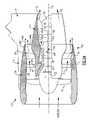
- FIG. 1Aillustrates a general partial fragmentary schematic view of a gas turbofan engine 10 suspended from an engine pylon P within an engine nacelle assembly N as is typical of an aircraft designed for subsonic operation.
- the turbofan engine 10includes a core engine within a core nacelle 12 that houses a low spool 14 and high spool 24 .
- the low spool 14includes a low pressure compressor 16 and low pressure turbine 18 .
- the low spool 14also drives a fan section 20 through a gear train 22 .
- the high spool 24includes a high pressure compressor 26 and high pressure turbine 28 .
- a combustor 30is arranged between the high pressure compressor 26 and high pressure turbine 28 .
- the low and high spools 14 , 24rotate about an engine axis of rotation A.
- the engine 10 in one non-limiting embodimentis a high-bypass geared architecture aircraft engine with a bypass ratio greater than ten (10:1), a turbofan diameter significantly larger than that of the low pressure compressor 16 , and the low pressure turbine 18 with a pressure ratio greater than 5:1.
- the gear train 22may be an epicycle gear train such as a planetary gear system or other gear system with a gear reduction ratio of greater than 2.5:1. It should be understood, however, that the above parameters are only exemplary of one non-limiting embodiment of a geared architecture engine and that this disclosure is applicable to other gas turbine engines including direct drive turbofans.
- the fan section 20communicates airflow into the core nacelle 12 to power the low pressure compressor 16 and the high pressure compressor 26 .
- Core airflow compressed by the low pressure compressor 16 and the high pressure compressor 26is mixed with the fuel in the combustor 30 and expanded over the high pressure turbine 28 and low pressure turbine 18 .
- the turbines 28 , 18are coupled for rotation with, respective, spools 24 , 14 to rotationally drive the compressors 26 , 16 and through the gear train 22 , the fan section 20 in response to the expansion.
- a primary combustion core gas exhaust flow Eexits the core nacelle 12 through a core nozzle 43 defined between the core nacelle 12 and a tail cone 32 .
- the core nacelle 12is supported within the fan nacelle 34 by circumferentially space structures 36 often generically referred to as Fan Exit Guide Vanes (FEGVs).
- FEGVsFan Exit Guide Vanes
- a secondary airflow or bypass flow path 40is defined between the core nacelle 12 and the fan nacelle 34 .
- the engine 10generates a high bypass flow arrangement with a bypass ratio in which approximately eighty percent of the airflow which enters the fan nacelle 34 becomes bypass flow B.
- the bypass flow Bcommunicates through the generally annular bypass flow path 40 and is discharged from the engine 10 through a variable area fan nozzle (VAFN) 42 which defines a primary bypass nozzle exit area 44 A between the fan nacelle 34 and the core nacelle 12 at a fan nacelle end segment 34 S of the fan nacelle 34 downstream of the fan section 20 .
- VAFNvariable area fan nozzle
- a secondary bypass nozzle exit area 44 Bis defined by the fan nacelle end segment 34 S.
- Thrustis a function of density, velocity, and area. One or more of these parameters can be manipulated to vary the amount and direction of thrust provided by the bypass flow B.
- the VAFN 42operates to effectively vary the area of the fan primary bypass nozzle exit area 44 A to selectively adjust the pressure ratio of the bypass flow B in response to a controller C.
- Low pressure ratio turbofansare desirable for their high propulsive efficiency. However, low pressure ratio fans may be inherently susceptible to fan stability/flutter problems at low power and low flight speeds.
- the VAFNallows the engine to change to a more favorable fan operating line at low power, avoiding the instability region, and still provide the relatively smaller nozzle area necessary to obtain a high-efficiency fan operating line at cruise.
- the fan section 20 of the engine 10is preferably designed for a particular flight condition—typically cruise at 0.8M and 35,000 feet. As the fan blades within the fan section 20 are efficiently designed at a particular fixed stagger angle for an efficient cruise condition, the VAFN 42 is operated to effectively vary the fan primary bypass nozzle exit area 44 A to adjust fan bypass air flow such that the angle of attack or incidence on the fan blades is maintained close to the design incidence for efficient engine operation at other flight conditions, such as landing and takeoff to thus provide optimized engine operation over a range of flight conditions with respect to performance and other operational parameters such as noise levels.
- the VAFN 42generally includes a regulator system 50 ( FIG. 1B ) having a first section 52 and a second section 54 movably mounted relative the first section 52 .
- the second section 54slides about the engine axis A relative the first section 52 to change the effective area of the secondary bypass nozzle exit area 44 B.
- the second section 54in one non-limiting embodiment, slides in response to an actuator 58 (illustrated schematically) to communicate at least a portion of the bypass flow B′ into the fan nacelle 34 and through the secondary bypass nozzle exit area 44 B.
- the VAFN 42changes the physical area and geometry of the bypass flow path 40 during particular flight conditions.
- the bypass flow Bis effectively altered by movement of the second section 54 relative the first section 52 between a closed position ( FIG. 2A ) and an open position ( FIG. 1D ) with a multitude of positions therebetween ( FIG. 1E ). It should be understood that an essentially infinite change in the bypass flow exit area may be provided by the regulator system 50 .
- the VAFN 42is opened by moving the second section 54 relative the first section 52 to open a tertiary flow path 60 in fluid communication with the fan nacelle end segment 34 S to increase the bypass flow exit area. That is, the bypass flow exit area with the tertiary flow path 60 in an open position ( FIG. 1D ) is greater than bypass flow exit area with the tertiary flow path 60 in a closed position ( FIG. 1C ).
- the tertiary flow path 60is incorporated within the fan nacelle 34 aft of the Fan Exit Guide Vanes 36 (FEGVs).
- the tertiary flow path 60communicates bypass airflow from a fan nacelle inner wall 34 I to the fan nacelle end segment 34 S defined between the fan nacelle inner wall 341 and the fan nacelle outer wall 34 E.
- the additional bypass flow which is exhausted from the fan nacelle end segment 34 Smay at least partially fill the trailing edge wake to increase overall engine thrust.
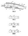
- another non-limiting embodimentincludes an ejection region 70 defined through fan nacelle outer wall 34 E ( FIG. 2B ). That is, the tertiary flow path 60 communicates bypass airflow from a fan nacelle inner wall 34 I to the through the ejection region 70 defined in the fan nacelle outer wall 34 A.
- the ejection region 70may include a perforated outer face sheet 72 supported by a structure 74 of the fan nacelle 34 ( FIG. 2C ). It should be understood that the ejection region 70 is illustrated in partial schematic cross-section and that various arrangements may be provided to support the perforated outer face sheet 68 .
- the regulator system 50communicates with the controller C to move the second section 54 relative the first section 52 to selectively communicate bypass airflow into the tertiary flow path 60 .
- the bypass airflowflows into the fan nacelle 34 through the regulator system 50 and exit through the ejection region 70 to vary the bypass flow exit area such that the bypass flow exit area with the tertiary flow path 60 in an open position is greater than exit area with the tertiary flow path 60 in a closed position. It should be understood that an essentially infinite change in the bypass flow exit area may be provided by the regulator system 50 .
- a gas turbine engine 80 of a relatively low bypass configurationgenerally includes at least a fan section 82 , a low pressure compressor section 84 , a high pressure compressor section 86 , a combustor section 88 , a turbine section 90 , an augmentor section 92 , and a nozzle section 94 .
- the low pressure compressor section 84 , high pressure compressor section 86 , combustor section 88 , and turbine section 90are generally referred to as the core engine.
- An axis of the engine Aextends longitudinally through these sections. It should be understood that the engine 80 may include alternative and additional sections.
- An engine duct structure 96 and an inner structure 98define an at least partially annular secondary flow path 100 at least partially around a perimeter of a primary flow path 102 which directs a primary combustion core gas exhaust flow (illustrated schematically by arrow E). It should be understood that the engine duct structure 96 may also at least partially define various airflow paths other than the disclosed secondary flow path 100 .
- the secondary flow path 100guides a secondary airflow S between the engine duct structure 96 and the inner structure 98 .
- the secondary airflow Sis typically sourced from the fan section and/or compressor section to provide a bypass flow.
- the secondary airflow Sis utilized for a multiple of purposes including, for example, cooling, pressurization, and mixing with the core gas exhaust flow E prior to discharge through the nozzle section 94 during particular operational profiles.
- the secondary airflow S as defined hereinis any airflow different from the primary combustion core gas exhaust flow E which may be provided as variable cycle third stream fan flow deployed, for example, by operating a set of outboard fan blades 12 B located in the secondary flow path 100 which surrounds the core engine.
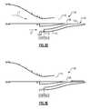
- the nozzle section 94generally includes a secondary flow duct 104 with a generally planar secondary nozzle 106 and a primary duct 108 with a generally planar primary nozzle 110 ( FIG. 3B ).
- the secondary flow duct 104communicates secondary airflow S therethrough and the primary duct 108 communicates primary combustion core gas exhaust flow E therethrough.
- the secondary flow duct 104 in one non-limiting embodimentis a bifurcated duct arrangement having a first duct 104 A and a second duct 104 B (not shown) which join at the secondary nozzle 32 ( FIG. 3C ).
- the primary duct 108is generally circular in cross-section at an upstream segment and transitions into the planar primary nozzle 110 at an aft end segment ( FIG. 3B ).
- the secondary nozzle 106 and the primary nozzle 110 in the disclosed non-limiting embodimentinclude a chevron-shaped trailing edge, however, it should be understood that any other configuration may alternatively be utilized.
- the regulator system 112controls secondary airflow S into the bypass flow duct 114 .
- the secondary nozzle 106is sized for minimum secondary airflow S requirements when the regulator system 38 is in a closed position.
- the total nozzle area of the secondary nozzle 106 and the ejection region 120provides for maximum secondary airflow S requirements. That is, the secondary flow exit area with the regulator system 112 in an open position is greater than secondary flow exit area with the regulator system 112 in a closed position. It should be understood that essentially infinite intermediate positions are available.
Landscapes
- Engineering & Computer Science (AREA)
- Chemical & Material Sciences (AREA)
- Combustion & Propulsion (AREA)
- Mechanical Engineering (AREA)
- General Engineering & Computer Science (AREA)
- Structures Of Non-Positive Displacement Pumps (AREA)
- Control Of Turbines (AREA)
- Jet Pumps And Other Pumps (AREA)
Abstract
Description
Claims (21)
Priority Applications (3)
| Application Number | Priority Date | Filing Date | Title |
|---|---|---|---|
| US12/193,822US8141366B2 (en) | 2008-08-19 | 2008-08-19 | Gas turbine engine with variable area fan nozzle |
| ES09721584.2TES2640761T3 (en) | 2008-03-20 | 2009-03-18 | Ferromagnetic powder composition and a process for its production |
| EP09251654.1AEP2157305B1 (en) | 2008-08-19 | 2009-06-26 | Gas turbine engine with variable area fan nozzle |
Applications Claiming Priority (1)
| Application Number | Priority Date | Filing Date | Title |
|---|---|---|---|
| US12/193,822US8141366B2 (en) | 2008-08-19 | 2008-08-19 | Gas turbine engine with variable area fan nozzle |
Publications (2)
| Publication Number | Publication Date |
|---|---|
| US20100043393A1 US20100043393A1 (en) | 2010-02-25 |
| US8141366B2true US8141366B2 (en) | 2012-03-27 |
Family
ID=40933544
Family Applications (1)
| Application Number | Title | Priority Date | Filing Date |
|---|---|---|---|
| US12/193,822Active2030-09-29US8141366B2 (en) | 2008-03-20 | 2008-08-19 | Gas turbine engine with variable area fan nozzle |
Country Status (2)
| Country | Link |
|---|---|
| US (1) | US8141366B2 (en) |
| EP (1) | EP2157305B1 (en) |
Cited By (10)
| Publication number | Priority date | Publication date | Assignee | Title |
|---|---|---|---|---|
| US20090320498A1 (en)* | 2008-06-25 | 2009-12-31 | Snecma | Cooling air bleed device in a turbomachine |
| US20090320497A1 (en)* | 2008-06-25 | 2009-12-31 | Snecma | Cooling air bleed device in a turbine engine |
| US20100104429A1 (en)* | 2008-10-24 | 2010-04-29 | Snecma | Device for tapping cooling air in a turbomachine |
| US8862362B2 (en) | 2012-07-02 | 2014-10-14 | United Technologies Corporation | Scheduling of variable area fan nozzle to optimize engine performance |
| RU2603945C1 (en)* | 2015-08-19 | 2016-12-10 | Открытое акционерное общество "Авиадвигатель" | Jet turbine engine with rectangular nozzle |
| US9605596B2 (en) | 2013-03-08 | 2017-03-28 | United Technologies Corporation | Duct blocker seal assembly for a gas turbine engine |
| US9617917B2 (en) | 2013-07-31 | 2017-04-11 | General Electric Company | Flow control assembly and methods of assembling the same |
| US9957895B2 (en) | 2013-02-28 | 2018-05-01 | United Technologies Corporation | Method and apparatus for collecting pre-diffuser airflow and routing it to combustor pre-swirlers |
| RU2731780C2 (en)* | 2015-03-26 | 2020-09-08 | Сафран Эркрафт Энджинз | Device with grids for ejection of microjets to reduce noise of jet stream of gas turbine engine |
| US11498660B2 (en) | 2013-03-11 | 2022-11-15 | Raytheon Technologies Corporation | Embedded engines in hybrid blended wing body |
Families Citing this family (25)
| Publication number | Priority date | Publication date | Assignee | Title |
|---|---|---|---|---|
| US20080273961A1 (en) | 2007-03-05 | 2008-11-06 | Rosenkrans William E | Flutter sensing and control system for a gas turbine engine |
| US9701415B2 (en) | 2007-08-23 | 2017-07-11 | United Technologies Corporation | Gas turbine engine with axial movable fan variable area nozzle |
| US9494084B2 (en) | 2007-08-23 | 2016-11-15 | United Technologies Corporation | Gas turbine engine with fan variable area nozzle for low fan pressure ratio |
| US10167813B2 (en) | 2007-08-23 | 2019-01-01 | United Technologies Corporation | Gas turbine engine with fan variable area nozzle to reduce fan instability |
| US20140174056A1 (en) | 2008-06-02 | 2014-06-26 | United Technologies Corporation | Gas turbine engine with low stage count low pressure turbine |
| FR2973443B1 (en)* | 2011-03-30 | 2016-07-22 | Snecma | POROUS PRIMARY COVER FOR TURBOREACTOR |
| WO2012174247A1 (en)* | 2011-06-14 | 2012-12-20 | Rolls-Royce North American Technologies, Inc. | Aircraft powerplant |
| US9115669B2 (en)* | 2011-10-28 | 2015-08-25 | United Technologies Corporation | Gas turbine engine exhaust nozzle cooling valve |
| US9260974B2 (en) | 2011-12-16 | 2016-02-16 | General Electric Company | System and method for active clearance control |
| WO2013141934A2 (en) | 2011-12-30 | 2013-09-26 | United Technologies Corporation | Gas turbine engine with fan variable area nozzle |
| SG11201403544TA (en)* | 2011-12-30 | 2014-07-30 | United Technologies Corp | Gas turbine engine with fan variable area nozzle for low fan pressure ratio |
| BR102012028942B1 (en)* | 2011-12-30 | 2021-06-15 | United Technologies Corporation | GAS TURBINE ENGINE |
| EP2798187A4 (en)* | 2011-12-30 | 2015-08-19 | United Technologies Corp | GAS TURBINE ENGINE EQUIPPED WITH VARIABLE SECTION NOZZLE FOR FAN TO REDUCE FAN INSTABILITY |
| US8246292B1 (en)* | 2012-01-31 | 2012-08-21 | United Technologies Corporation | Low noise turbine for geared turbofan engine |
| US20160130949A1 (en) | 2012-01-31 | 2016-05-12 | United Technologies Corporation | Low noise turbine for geared turbofan engine |
| US9624834B2 (en) | 2012-09-28 | 2017-04-18 | United Technologies Corporation | Low noise compressor rotor for geared turbofan engine |
| US20160138474A1 (en) | 2012-09-28 | 2016-05-19 | United Technologies Corporation | Low noise compressor rotor for geared turbofan engine |
| US9863366B2 (en)* | 2013-03-13 | 2018-01-09 | Rolls-Royce North American Technologies Inc. | Exhaust nozzle apparatus and method for multi stream aircraft engine |
| US10605172B2 (en) | 2013-03-14 | 2020-03-31 | United Technologies Corporation | Low noise turbine for geared gas turbine engine |
| US11719161B2 (en) | 2013-03-14 | 2023-08-08 | Raytheon Technologies Corporation | Low noise turbine for geared gas turbine engine |
| US9009966B2 (en) | 2013-03-15 | 2015-04-21 | Northrop Gurmman Systems Corporation | Internal/external single expansion ramp nozzle with integrated third stream |
| EP2982854B1 (en)* | 2014-08-08 | 2023-03-01 | Raytheon Technologies Corporation | Convergent divergent exit nozzle for a gas turbine engine |
| US10352248B2 (en) | 2014-10-01 | 2019-07-16 | United Technologies Corporation | Synchronized air modulating system |
| FR3034142B1 (en)* | 2015-03-26 | 2017-04-07 | Snecma | MICROJET EJECTION GRID DEVICE FOR REDUCING JET NOISE FROM A TURBOMACHINE |
| FR3067406B1 (en)* | 2017-06-13 | 2019-07-12 | Airbus Operations | THRUST INVERTER SYSTEM HAVING LIMITED AERODYNAMIC DISTURBANCES |
Citations (29)
| Publication number | Priority date | Publication date | Assignee | Title |
|---|---|---|---|---|
| US3161018A (en) | 1960-07-11 | 1964-12-15 | Nord Aviation | Combined turbojet-ramjet engine |
| US3673802A (en) | 1970-06-18 | 1972-07-04 | Gen Electric | Fan engine with counter rotating geared core booster |
| US3879941A (en) | 1973-05-21 | 1975-04-29 | Gen Electric | Variable cycle gas turbine engine |
| US3931708A (en) | 1973-10-11 | 1976-01-13 | United Technologies Corporation | Variable flap for a variable pitch ducted fan propulsor |
| US4043121A (en) | 1975-01-02 | 1977-08-23 | General Electric Company | Two-spool variable cycle engine |
| US4068471A (en) | 1975-06-16 | 1978-01-17 | General Electric Company | Variable cycle engine with split fan section |
| US4085583A (en) | 1975-03-31 | 1978-04-25 | The Boeing Company | Method for selectively switching motive fluid supply to an aft turbine of a multicycle engine |
| US4175384A (en) | 1977-08-02 | 1979-11-27 | General Electric Company | Individual bypass injector valves for a double bypass variable cycle turbofan engine |
| US4409788A (en) | 1979-04-23 | 1983-10-18 | General Electric Company | Actuation system for use on a gas turbine engine |
| EP0567277A1 (en) | 1992-04-20 | 1993-10-27 | General Electric Company | Bypass injector valve for variable cycle aircraft engines |
| US5261227A (en) | 1992-11-24 | 1993-11-16 | General Electric Company | Variable specific thrust turbofan engine |
| US5388964A (en) | 1993-09-14 | 1995-02-14 | General Electric Company | Hybrid rotor blade |
| US5402638A (en) | 1993-10-04 | 1995-04-04 | General Electric Company | Spillage drag reducing flade engine |
| US5404713A (en) | 1993-10-04 | 1995-04-11 | General Electric Company | Spillage drag and infrared reducing flade engine |
| US5699662A (en)* | 1996-05-28 | 1997-12-23 | Lockheed Martin Corporation | Infrared suppression exhaust duct system for a turboprop propulsion system for an aircraft |
| US5778659A (en) | 1994-10-20 | 1998-07-14 | United Technologies Corporation | Variable area fan exhaust nozzle having mechanically separate sleeve and thrust reverser actuation systems |
| US5794432A (en) | 1996-08-27 | 1998-08-18 | Diversitech, Inc. | Variable pressure and variable air flow turbofan engines |
| US5806302A (en) | 1996-09-24 | 1998-09-15 | Rohr, Inc. | Variable fan exhaust area nozzle for aircraft gas turbine engine with thrust reverser |
| US5806303A (en) | 1996-03-29 | 1998-09-15 | General Electric Company | Turbofan engine with a core driven supercharged bypass duct and fixed geometry nozzle |
| US5809772A (en) | 1996-03-29 | 1998-09-22 | General Electric Company | Turbofan engine with a core driven supercharged bypass duct |
| US5867980A (en) | 1996-12-17 | 1999-02-09 | General Electric Company | Turbofan engine with a low pressure turbine driven supercharger in a bypass duct operated by a fuel rich combustor and an afterburner |
| US5988980A (en) | 1997-09-08 | 1999-11-23 | General Electric Company | Blade assembly with splitter shroud |
| US6318070B1 (en) | 2000-03-03 | 2001-11-20 | United Technologies Corporation | Variable area nozzle for gas turbine engines driven by shape memory alloy actuators |
| US6546716B2 (en) | 2001-04-26 | 2003-04-15 | Jean-Pierre Lair | Jet engine nozzle with variable thrust vectoring and exhaust area |
| US6729575B2 (en) | 2002-04-01 | 2004-05-04 | Lockheed Martin Corporation | Propulsion system for a vertical and short takeoff and landing aircraft |
| US6901739B2 (en) | 2003-10-07 | 2005-06-07 | General Electric Company | Gas turbine engine with variable pressure ratio fan system |
| US7010905B2 (en)* | 2003-02-21 | 2006-03-14 | The Nordam Group, Inc. | Ventilated confluent exhaust nozzle |
| US7174704B2 (en) | 2004-07-23 | 2007-02-13 | General Electric Company | Split shroud exhaust nozzle |
| US20070186535A1 (en)* | 2006-02-13 | 2007-08-16 | General Electric Company | Double bypass turbofan |
Family Cites Families (1)
| Publication number | Priority date | Publication date | Assignee | Title |
|---|---|---|---|---|
| US7581385B2 (en)* | 2005-11-03 | 2009-09-01 | United Technologies Corporation | Metering sheet and iso-grid arrangement for a non axi-symmetric shaped cooling liner within a gas turbine engine exhaust duct |
- 2008
- 2008-08-19USUS12/193,822patent/US8141366B2/enactiveActive
- 2009
- 2009-06-26EPEP09251654.1Apatent/EP2157305B1/enactiveActive
Patent Citations (32)
| Publication number | Priority date | Publication date | Assignee | Title |
|---|---|---|---|---|
| US3161018A (en) | 1960-07-11 | 1964-12-15 | Nord Aviation | Combined turbojet-ramjet engine |
| US3673802A (en) | 1970-06-18 | 1972-07-04 | Gen Electric | Fan engine with counter rotating geared core booster |
| US3879941A (en) | 1973-05-21 | 1975-04-29 | Gen Electric | Variable cycle gas turbine engine |
| US3931708A (en) | 1973-10-11 | 1976-01-13 | United Technologies Corporation | Variable flap for a variable pitch ducted fan propulsor |
| US4043121A (en) | 1975-01-02 | 1977-08-23 | General Electric Company | Two-spool variable cycle engine |
| US4085583A (en) | 1975-03-31 | 1978-04-25 | The Boeing Company | Method for selectively switching motive fluid supply to an aft turbine of a multicycle engine |
| US4068471A (en) | 1975-06-16 | 1978-01-17 | General Electric Company | Variable cycle engine with split fan section |
| US4175384A (en) | 1977-08-02 | 1979-11-27 | General Electric Company | Individual bypass injector valves for a double bypass variable cycle turbofan engine |
| US4409788A (en) | 1979-04-23 | 1983-10-18 | General Electric Company | Actuation system for use on a gas turbine engine |
| EP0567277A1 (en) | 1992-04-20 | 1993-10-27 | General Electric Company | Bypass injector valve for variable cycle aircraft engines |
| US5261227A (en) | 1992-11-24 | 1993-11-16 | General Electric Company | Variable specific thrust turbofan engine |
| US5388964A (en) | 1993-09-14 | 1995-02-14 | General Electric Company | Hybrid rotor blade |
| US5402638A (en) | 1993-10-04 | 1995-04-04 | General Electric Company | Spillage drag reducing flade engine |
| US5404713A (en) | 1993-10-04 | 1995-04-11 | General Electric Company | Spillage drag and infrared reducing flade engine |
| US5778659A (en) | 1994-10-20 | 1998-07-14 | United Technologies Corporation | Variable area fan exhaust nozzle having mechanically separate sleeve and thrust reverser actuation systems |
| US5806303A (en) | 1996-03-29 | 1998-09-15 | General Electric Company | Turbofan engine with a core driven supercharged bypass duct and fixed geometry nozzle |
| US5809772A (en) | 1996-03-29 | 1998-09-22 | General Electric Company | Turbofan engine with a core driven supercharged bypass duct |
| US5699662A (en)* | 1996-05-28 | 1997-12-23 | Lockheed Martin Corporation | Infrared suppression exhaust duct system for a turboprop propulsion system for an aircraft |
| US5794432A (en) | 1996-08-27 | 1998-08-18 | Diversitech, Inc. | Variable pressure and variable air flow turbofan engines |
| US6292763B1 (en) | 1996-08-27 | 2001-09-18 | Diversitech, Inc. | Methods for designing variable cycle gas turbine engines |
| US5806302A (en) | 1996-09-24 | 1998-09-15 | Rohr, Inc. | Variable fan exhaust area nozzle for aircraft gas turbine engine with thrust reverser |
| US5867980A (en) | 1996-12-17 | 1999-02-09 | General Electric Company | Turbofan engine with a low pressure turbine driven supercharger in a bypass duct operated by a fuel rich combustor and an afterburner |
| US5988980A (en) | 1997-09-08 | 1999-11-23 | General Electric Company | Blade assembly with splitter shroud |
| US7004047B2 (en) | 2000-03-03 | 2006-02-28 | United Technologies Corporation | Variable area nozzle for gas turbine engines driven by shape memory alloy actuators |
| US6735936B2 (en) | 2000-03-03 | 2004-05-18 | United Technologies Corporation | Variable area nozzle for gas turbine engines driven by shape memory alloy actuators |
| US6318070B1 (en) | 2000-03-03 | 2001-11-20 | United Technologies Corporation | Variable area nozzle for gas turbine engines driven by shape memory alloy actuators |
| US6546716B2 (en) | 2001-04-26 | 2003-04-15 | Jean-Pierre Lair | Jet engine nozzle with variable thrust vectoring and exhaust area |
| US6729575B2 (en) | 2002-04-01 | 2004-05-04 | Lockheed Martin Corporation | Propulsion system for a vertical and short takeoff and landing aircraft |
| US7010905B2 (en)* | 2003-02-21 | 2006-03-14 | The Nordam Group, Inc. | Ventilated confluent exhaust nozzle |
| US6901739B2 (en) | 2003-10-07 | 2005-06-07 | General Electric Company | Gas turbine engine with variable pressure ratio fan system |
| US7174704B2 (en) | 2004-07-23 | 2007-02-13 | General Electric Company | Split shroud exhaust nozzle |
| US20070186535A1 (en)* | 2006-02-13 | 2007-08-16 | General Electric Company | Double bypass turbofan |
Cited By (19)
| Publication number | Priority date | Publication date | Assignee | Title |
|---|---|---|---|---|
| US20090320498A1 (en)* | 2008-06-25 | 2009-12-31 | Snecma | Cooling air bleed device in a turbomachine |
| US20090320497A1 (en)* | 2008-06-25 | 2009-12-31 | Snecma | Cooling air bleed device in a turbine engine |
| US8408009B2 (en)* | 2008-06-25 | 2013-04-02 | Snecma | Cooling air bleed device in a turbine engine |
| US8448448B2 (en)* | 2008-06-25 | 2013-05-28 | Snecma | Cooling air bleed device in a turbomachine |
| US20100104429A1 (en)* | 2008-10-24 | 2010-04-29 | Snecma | Device for tapping cooling air in a turbomachine |
| US8397513B2 (en)* | 2008-10-24 | 2013-03-19 | Snecma | Device for tapping cooling air in a turbomachine |
| US8862362B2 (en) | 2012-07-02 | 2014-10-14 | United Technologies Corporation | Scheduling of variable area fan nozzle to optimize engine performance |
| US10808616B2 (en) | 2013-02-28 | 2020-10-20 | Raytheon Technologies Corporation | Method and apparatus for handling pre-diffuser airflow for cooling high pressure turbine components |
| US10669938B2 (en) | 2013-02-28 | 2020-06-02 | Raytheon Technologies Corporation | Method and apparatus for selectively collecting pre-diffuser airflow |
| US10760491B2 (en) | 2013-02-28 | 2020-09-01 | Raytheon Technologies Corporation | Method and apparatus for handling pre-diffuser airflow for use in adjusting a temperature profile |
| US9957895B2 (en) | 2013-02-28 | 2018-05-01 | United Technologies Corporation | Method and apparatus for collecting pre-diffuser airflow and routing it to combustor pre-swirlers |
| US10337406B2 (en) | 2013-02-28 | 2019-07-02 | United Technologies Corporation | Method and apparatus for handling pre-diffuser flow for cooling high pressure turbine components |
| US10704468B2 (en) | 2013-02-28 | 2020-07-07 | Raytheon Technologies Corporation | Method and apparatus for handling pre-diffuser airflow for cooling high pressure turbine components |
| US9605596B2 (en) | 2013-03-08 | 2017-03-28 | United Technologies Corporation | Duct blocker seal assembly for a gas turbine engine |
| US10578026B2 (en) | 2013-03-08 | 2020-03-03 | United Technologies Corporation | Duct blocker seal assembly for a gas turbine engine |
| US11498660B2 (en) | 2013-03-11 | 2022-11-15 | Raytheon Technologies Corporation | Embedded engines in hybrid blended wing body |
| US9617917B2 (en) | 2013-07-31 | 2017-04-11 | General Electric Company | Flow control assembly and methods of assembling the same |
| RU2731780C2 (en)* | 2015-03-26 | 2020-09-08 | Сафран Эркрафт Энджинз | Device with grids for ejection of microjets to reduce noise of jet stream of gas turbine engine |
| RU2603945C1 (en)* | 2015-08-19 | 2016-12-10 | Открытое акционерное общество "Авиадвигатель" | Jet turbine engine with rectangular nozzle |
Also Published As
| Publication number | Publication date |
|---|---|
| US20100043393A1 (en) | 2010-02-25 |
| EP2157305A2 (en) | 2010-02-24 |
| EP2157305A3 (en) | 2012-10-24 |
| EP2157305B1 (en) | 2014-02-26 |
Similar Documents
| Publication | Publication Date | Title |
|---|---|---|
| US8141366B2 (en) | Gas turbine engine with variable area fan nozzle | |
| US11391240B2 (en) | Gas turbine engine bifurcation located fan variable area nozzle | |
| US9745918B2 (en) | Gas turbine engine with noise attenuating variable area fan nozzle | |
| US8365515B2 (en) | Gas turbine engine with fan variable area nozzle, nacelle assembly and method of varying area of a fan nozzle | |
| US8459035B2 (en) | Gas turbine engine with low fan pressure ratio | |
| US8443586B2 (en) | Variable area fan nozzle bearing track | |
| US10047628B2 (en) | Gas turbine engine with fan variable area nozzle for low fan pressure ratio | |
| US8739515B2 (en) | Variable area fan nozzle cowl airfoil | |
| US8662417B2 (en) | Gas turbine engine fan variable area nozzle with swivable insert system | |
| US7673442B2 (en) | Turbofan engine cowl assembly | |
| US20090053058A1 (en) | Gas turbine engine with axial movable fan variable area nozzle | |
| US20110171007A1 (en) | Convertible fan system | |
| US20110167792A1 (en) | Adaptive engine | |
| US20100005777A1 (en) | Dual function cascade integrated variable area fan nozzle and thrust reverser | |
| US20110120078A1 (en) | Variable area fan nozzle track | |
| US20100050595A1 (en) | Gas turbine engine with axial movable fan variable area nozzle | |
| US20110302907A1 (en) | Variable area fan nozzle | |
| JP2008144764A (en) | System and method for passively directing aircraft engine nozzle fluid | |
| US20130149111A1 (en) | Gas turbine engine with fan variable area nozzle for low fan pressure ratio | |
| US20160053717A9 (en) | Gas turbine engine with fan variable area nozzle to reduce fan instability |
Legal Events
| Date | Code | Title | Description |
|---|---|---|---|
| AS | Assignment | Owner name:UNITED TECHNOLOGIES CORPORATION,CONNECTICUT Free format text:ASSIGNMENT OF ASSIGNORS INTEREST;ASSIGNORS:ZAMORA, SEAN P.;MURPHY, MICHAEL JOSEPH;REEL/FRAME:021406/0007 Effective date:20080811 Owner name:UNITED TECHNOLOGIES CORPORATION, CONNECTICUT Free format text:ASSIGNMENT OF ASSIGNORS INTEREST;ASSIGNORS:ZAMORA, SEAN P.;MURPHY, MICHAEL JOSEPH;REEL/FRAME:021406/0007 Effective date:20080811 | |
| STCF | Information on status: patent grant | Free format text:PATENTED CASE | |
| FPAY | Fee payment | Year of fee payment:4 | |
| MAFP | Maintenance fee payment | Free format text:PAYMENT OF MAINTENANCE FEE, 8TH YEAR, LARGE ENTITY (ORIGINAL EVENT CODE: M1552); ENTITY STATUS OF PATENT OWNER: LARGE ENTITY Year of fee payment:8 | |
| AS | Assignment | Owner name:RAYTHEON TECHNOLOGIES CORPORATION, MASSACHUSETTS Free format text:CHANGE OF NAME;ASSIGNOR:UNITED TECHNOLOGIES CORPORATION;REEL/FRAME:054062/0001 Effective date:20200403 | |
| AS | Assignment | Owner name:RAYTHEON TECHNOLOGIES CORPORATION, CONNECTICUT Free format text:CORRECTIVE ASSIGNMENT TO CORRECT THE AND REMOVE PATENT APPLICATION NUMBER 11886281 AND ADD PATENT APPLICATION NUMBER 14846874. TO CORRECT THE RECEIVING PARTY ADDRESS PREVIOUSLY RECORDED AT REEL: 054062 FRAME: 0001. ASSIGNOR(S) HEREBY CONFIRMS THE CHANGE OF ADDRESS;ASSIGNOR:UNITED TECHNOLOGIES CORPORATION;REEL/FRAME:055659/0001 Effective date:20200403 | |
| AS | Assignment | Owner name:RTX CORPORATION, CONNECTICUT Free format text:CHANGE OF NAME;ASSIGNOR:RAYTHEON TECHNOLOGIES CORPORATION;REEL/FRAME:064714/0001 Effective date:20230714 | |
| MAFP | Maintenance fee payment | Free format text:PAYMENT OF MAINTENANCE FEE, 12TH YEAR, LARGE ENTITY (ORIGINAL EVENT CODE: M1553); ENTITY STATUS OF PATENT OWNER: LARGE ENTITY Year of fee payment:12 |