US8140414B2 - System and method for controlling a utility meter - Google Patents
System and method for controlling a utility meterDownload PDFInfo
- Publication number
- US8140414B2 US8140414B2US11/824,131US82413107AUS8140414B2US 8140414 B2US8140414 B2US 8140414B2US 82413107 AUS82413107 AUS 82413107AUS 8140414 B2US8140414 B2US 8140414B2
- Authority
- US
- United States
- Prior art keywords
- collar unit
- meter
- power
- utility
- data
- Prior art date
- Legal status (The legal status is an assumption and is not a legal conclusion. Google has not performed a legal analysis and makes no representation as to the accuracy of the status listed.)
- Active
Links
Images


Classifications
- G—PHYSICS
- G01—MEASURING; TESTING
- G01D—MEASURING NOT SPECIALLY ADAPTED FOR A SPECIFIC VARIABLE; ARRANGEMENTS FOR MEASURING TWO OR MORE VARIABLES NOT COVERED IN A SINGLE OTHER SUBCLASS; TARIFF METERING APPARATUS; MEASURING OR TESTING NOT OTHERWISE PROVIDED FOR
- G01D4/00—Tariff metering apparatus
- G01D4/002—Remote reading of utility meters
- G01D4/004—Remote reading of utility meters to a fixed location
- G—PHYSICS
- G06—COMPUTING OR CALCULATING; COUNTING
- G06Q—INFORMATION AND COMMUNICATION TECHNOLOGY [ICT] SPECIALLY ADAPTED FOR ADMINISTRATIVE, COMMERCIAL, FINANCIAL, MANAGERIAL OR SUPERVISORY PURPOSES; SYSTEMS OR METHODS SPECIALLY ADAPTED FOR ADMINISTRATIVE, COMMERCIAL, FINANCIAL, MANAGERIAL OR SUPERVISORY PURPOSES, NOT OTHERWISE PROVIDED FOR
- G06Q20/00—Payment architectures, schemes or protocols
- G06Q20/08—Payment architectures
- G06Q20/10—Payment architectures specially adapted for electronic funds transfer [EFT] systems; specially adapted for home banking systems
- G06Q20/102—Bill distribution or payments
- G—PHYSICS
- G06—COMPUTING OR CALCULATING; COUNTING
- G06Q—INFORMATION AND COMMUNICATION TECHNOLOGY [ICT] SPECIALLY ADAPTED FOR ADMINISTRATIVE, COMMERCIAL, FINANCIAL, MANAGERIAL OR SUPERVISORY PURPOSES; SYSTEMS OR METHODS SPECIALLY ADAPTED FOR ADMINISTRATIVE, COMMERCIAL, FINANCIAL, MANAGERIAL OR SUPERVISORY PURPOSES, NOT OTHERWISE PROVIDED FOR
- G06Q30/00—Commerce
- G06Q30/04—Billing or invoicing
- G—PHYSICS
- G06—COMPUTING OR CALCULATING; COUNTING
- G06Q—INFORMATION AND COMMUNICATION TECHNOLOGY [ICT] SPECIALLY ADAPTED FOR ADMINISTRATIVE, COMMERCIAL, FINANCIAL, MANAGERIAL OR SUPERVISORY PURPOSES; SYSTEMS OR METHODS SPECIALLY ADAPTED FOR ADMINISTRATIVE, COMMERCIAL, FINANCIAL, MANAGERIAL OR SUPERVISORY PURPOSES, NOT OTHERWISE PROVIDED FOR
- G06Q40/00—Finance; Insurance; Tax strategies; Processing of corporate or income taxes
- G06Q40/03—Credit; Loans; Processing thereof
- G—PHYSICS
- G06—COMPUTING OR CALCULATING; COUNTING
- G06Q—INFORMATION AND COMMUNICATION TECHNOLOGY [ICT] SPECIALLY ADAPTED FOR ADMINISTRATIVE, COMMERCIAL, FINANCIAL, MANAGERIAL OR SUPERVISORY PURPOSES; SYSTEMS OR METHODS SPECIALLY ADAPTED FOR ADMINISTRATIVE, COMMERCIAL, FINANCIAL, MANAGERIAL OR SUPERVISORY PURPOSES, NOT OTHERWISE PROVIDED FOR
- G06Q50/00—Information and communication technology [ICT] specially adapted for implementation of business processes of specific business sectors, e.g. utilities or tourism
- G06Q50/06—Energy or water supply
- G—PHYSICS
- G01—MEASURING; TESTING
- G01D—MEASURING NOT SPECIALLY ADAPTED FOR A SPECIFIC VARIABLE; ARRANGEMENTS FOR MEASURING TWO OR MORE VARIABLES NOT COVERED IN A SINGLE OTHER SUBCLASS; TARIFF METERING APPARATUS; MEASURING OR TESTING NOT OTHERWISE PROVIDED FOR
- G01D2204/00—Indexing scheme relating to details of tariff-metering apparatus
- G01D2204/10—Analysing; Displaying
- G01D2204/18—Remote displaying of utility meter readings
- Y—GENERAL TAGGING OF NEW TECHNOLOGICAL DEVELOPMENTS; GENERAL TAGGING OF CROSS-SECTIONAL TECHNOLOGIES SPANNING OVER SEVERAL SECTIONS OF THE IPC; TECHNICAL SUBJECTS COVERED BY FORMER USPC CROSS-REFERENCE ART COLLECTIONS [XRACs] AND DIGESTS
- Y02—TECHNOLOGIES OR APPLICATIONS FOR MITIGATION OR ADAPTATION AGAINST CLIMATE CHANGE
- Y02B—CLIMATE CHANGE MITIGATION TECHNOLOGIES RELATED TO BUILDINGS, e.g. HOUSING, HOUSE APPLIANCES OR RELATED END-USER APPLICATIONS
- Y02B90/00—Enabling technologies or technologies with a potential or indirect contribution to GHG emissions mitigation
- Y02B90/20—Smart grids as enabling technology in buildings sector
- Y—GENERAL TAGGING OF NEW TECHNOLOGICAL DEVELOPMENTS; GENERAL TAGGING OF CROSS-SECTIONAL TECHNOLOGIES SPANNING OVER SEVERAL SECTIONS OF THE IPC; TECHNICAL SUBJECTS COVERED BY FORMER USPC CROSS-REFERENCE ART COLLECTIONS [XRACs] AND DIGESTS
- Y04—INFORMATION OR COMMUNICATION TECHNOLOGIES HAVING AN IMPACT ON OTHER TECHNOLOGY AREAS
- Y04S—SYSTEMS INTEGRATING TECHNOLOGIES RELATED TO POWER NETWORK OPERATION, COMMUNICATION OR INFORMATION TECHNOLOGIES FOR IMPROVING THE ELECTRICAL POWER GENERATION, TRANSMISSION, DISTRIBUTION, MANAGEMENT OR USAGE, i.e. SMART GRIDS
- Y04S20/00—Management or operation of end-user stationary applications or the last stages of power distribution; Controlling, monitoring or operating thereof
- Y04S20/30—Smart metering, e.g. specially adapted for remote reading
Definitions
- the inventionprovides a long range, communication independent, collar-based, device with associated software and firmware, capable of power supply output, electric service disconnect/reconnect, limiting current, metering information, and communicating with and controlling local area network devices for provision of application functions desirable in the utility industry.
- the inventionallows utility service providers the ability to obtain real time metering information via a collar-mounted device that is installed between the existing meter socket and the electric meter.
- metersMost utility providers measure the usage of energy or gas or water through devices called meters. These meters may be electro-mechanical or electronic or a combination of both. Most utilities obtain monthly meter readings for the purposes of rendering a bill based on the consumption measured by the meter. Obtaining meter readings can be a laborious and costly process for the utility, as historically meter reading required individuals going house to house and manually reading the meter and recording the results.
- a disadvantage of the historical metering approachis that metering has been viewed as only the “cash register” for the utility. Hence utilities have not been focused on the benefits of communicating to the meter, and instead have targeted merely receiving information from the meter. Utilities typically render a bill to their customers monthly and the customers have no way of validating energy use unless they want to dispute the bill.
- the present inventionallows the utility to interrogate the electric system at the premise in near real time. This encompasses much more than meter reading or measuring voltage as historically performed, and also includes information about voltage anomalies, load profiling and estimation, and energy efficiency estimation.
- the present inventionallows a true near-real-time diagnostic system of the electric service which now opens the door for a variety of applications to help not only the utility provide better service, but to also allow the customer for the first time to have the necessary information to help control energy consumption and improve efficiency.
- the present inventionis capable of communicating bi-directionally through a variety of communication platforms including, but not limited to, analog cell systems, digital cell systems, Ethernet, short range radio wireless, ZigBee, power line carrier, Hybrid-Fiber Coax, RF, WiFi, and WiMax.
- the systemallows for the addition or substitution of other backhaul methodologies. More importantly, the present invention has reduced duplication of functionality, reduced equipment size and cost to achieve that functionality.
- the present inventionfurther provides application functionality that currently does not exist, specifically the ability to read meters via Ethernet or other communications platforms and provide a power supply in the same collar device. Existing technology can read meters and store voltages for the purposes of measuring electric energy and voltage. The present invention takes that information and transforms it into intelligence for the utility and the customer.
- meter reading devicesread meter registers and voltage and transmit that information back to the utility via an Ethernet network. These devices include an Ethernet connection in the meter itself. Therefore, in order to add functionality to the devices, the existing meters must be replaced. Because the present invention is collar-based, it can be used with existing meters.
- the present inventionprovides the utility customer access to the same, real-time information available to the utility. This capability is achieved through a customer interface unit (CIU) located in the premise that allows the customer to view metering information including: voltage current information; power quality information including voltage transients; power factor, harmonics; energy usage information; and even anticipated energy consumption, over a specified time period.
- CUAcustomer interface unit
- the informationmay be communicated wirelessly or through the power line carrier between the collar-based meter device and the internal customer display unit in a real time environment.
- This informationincludes real time kilowatt hours, voltage profile, total harmonics distortion and power factor. This information is measured over a 1 minute, 5 minute, 15 minute interval basis, or variable time basis.
- the voltage profilemay be presented over the same time frames as well. Temperature inside the collar device is also available.
- the system of the present inventionincludes the ability to display energy consumption by appliance and provide the utility the opportunity to utilize the system for demand side management and supports a new level of energy education at the customer level.
- FIG. 1is a block diagram illustrating a system in accordance with an exemplary embodiment of the present disclosure.
- FIG. 2depicts an exemplary collar of the system of FIG. 1 .
- FIG. 3depicts an exemplary billing server of the system of FIG. 1 .
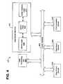
- FIG. 4depicts an exemplary data server of the system of FIG. 1 .
- FIG. 5depicts an exemplary customer interface unit of the system of FIG. 1 .
- FIG. 6is a flow chart illustrating exemplary architecture and functionality of the remote meter management logic of FIG. 3 .
- FIG. 7is a flow chart illustrating exemplary architecture and functionality of the meter management logic of FIG. 2 .
- FIG. 8is a flow chart illustrating alternative exemplary architecture and functionality of the remote meter management logic of FIG. 3 .
- FIG. 9depicts an exemplary embodiment of the invention in a wired Ethernet version.
- FIG. 1illustrates a collar-based utility meter control system 100 in accordance with an exemplary embodiment of the present disclosure.
- the system 100comprises an adapter collar 103 communicating with a utility meter 102 and a customer interface unit (CIU) 104 .
- Utility meter 102may be of any type provided by a utility service provider, and in some embodiments is an American National Standards Industry (ANSI) C12 meter.
- ANSIAmerican National Standards Industry
- Collar 103connects between a standard utility meter socket housing 108 and utility meter 102 and communicates via a network 105 to billing server 106 , data server 107 , and access device 109 .
- Customer 101accesses CIU data 523 [ FIG. 5 ] via the CIU 104 .
- Access device 109provides user interfaces at the utility (not shown) for functions such as hardware configuration, monitoring and control, system administration, interfaces to other electronic systems, historical archiving, alarm generation and message forwarding, and report generation.
- Access device 109may be any suitable computer known in the art, and in one embodiment is a “thin client” device which depends primarily on the data server 107 for processing activities, and focuses on conveying input and output between the utility user (not shown) and the data server 107 .
- Network 105may be of any type network or networks known in the art, such as Ethernet, analog cellular, digital cellular, short range radio wireless, Wifi, WiMax, broadband over power line, coaxial cable, and the like.
- Network 105may be any combination of hardware, software, or both.
- network 105 Wide Area Network (WAN) methodologieswill be utilized for communicating information and control over the network 105 .
- the type of WANwill determine whether a Local Area Network (LAN) is necessary. Where the WAN requires ongoing communication charges (i.e. GSM/GPRS), a WAN connection will not be available at all meters 102 , or the cost of the WAN hardware is prohibitive, a LAN may be established between local vicinity collars 103 and other utility-related devices (such as load management devices, solid state thermostats, etc. (not shown)) to reduce the number of WAN end points (not shown) required in the network 105 .
- LANLocal Area Network
- a customer 101 of a utility servicepre-pays for his utility services. This can be done in a form of a check, cash, credit card, ATM card, or other form of payment approved by the utility service.
- the billing server 106stores data indicative of any unapplied payments. “Unapplied payments” refers to amounts that have been pre-paid but not yet applied to the customer's billing account.
- FIG. 2depicts an exemplary collar 103 of the present disclosure.
- the exemplary collar 103generally comprises processing unit 204 , collar output device 224 , collar input device 208 , meter interface 210 and collar communication device 212 , all communicating over local interface 206 .
- Collar 103further comprises meter management logic 214 , meter data 223 , and pre-pay data 225 .
- Meter management logic 214 , meter data 223 , and pre-pay data 225can be software, hardware, or a combination thereof.
- meter management logic 214 , meter data 223 , and pre-pay data 225are shown as stored in memory 202 .
- Memorymay be of any suitable type of computer memory known in the art, such as RAM, ROM, flash-type, and the like.
- meter management logic 214 and the meter data 223are shown in FIG. 2 as software stored in memory 202 .
- the meter management logic 214 and the meter data 223can be stored and transported on any computer-readable medium for use by or in connection with an instruction execution system, apparatus, or device, such as a computer-based system, processor-containing system, or other system that can fetch the instructions from the instruction execution system, apparatus, or device and execute the instructions.
- a “computer-readable medium”can be any means that can contain, store, communicate, propagate, or transport the program for use by or in connection with the instruction execution system, apparatus, or device.
- the computer readable mediumcan be, for example but not limited to, an electronic, magnetic, optical, electromagnetic, infrared, or semiconductor system, apparatus, device, or propagation medium.
- the computer-readable mediumcould even be paper or another suitable medium upon which the program is printed, as the program can be electronically captured, via for instance optical scanning of the paper or other medium, then compiled, interpreted or otherwise processed in a suitable manner if necessary, and then stored in a computer memory.
- Processing unit 204may be a digital processor or other type of circuitry configured to run the meter management logic 214 by processing and executing the instructions of the meter management logic 214 .
- Processing unit 204communicates to and drives the other elements within the collar 103 via a local interface 206 , which can include one or more buses.
- collar input device 208provides a direct interface to collar components as may be required, for example, for troubleshooting purposes or to download firmware directly to processing unit 204 .
- Collar input device 228may be software, hardware, or a combination thereof.
- collar output device 224for example, a universal serial bus (USB) port or other type network device, connects the collar 103 with the network 105 for communication with the billing server 106 and/or data server 107 ( FIG. 1 ).
- USBuniversal serial bus
- Meter management logic 214performs a daily read of the meter 102 via meter interface 210 and stores such meter data 223 obtained in memory 202 .
- Meter interface 210connects the collar 103 to meter 102 , and may be software, hardware, or a combination thereof.
- Meter management logic 214also downloads meter data 223 to the billing server 106 via communication device 212 .
- Collar communication device 121interfaces between the collar 103 and the network 105 and may comprise software, hardware, or a combination thereof.
- Collar communication device 212may consist of, for example, a LAN radio, a WAN radio, an AMPS radio, or other devices suitable for connection to network 105 .
- Meter management logic 214also retrieves customer data 323 [ FIG. 3 ] and server data 423 [ FIG. 4 ] from the billing server 106 across the network 105 via collar communication device 212 .
- Meter management logic 214further provides meter data 223 to other devices, such as the CIU 104 [ FIG. 1 ], via output device 224 , which may be software, hardware, or a combination thereof.
- CIU 104provides end customers 101 with a display of CIU data 523 [ FIG. 5 ].
- customersmay provide input to the utility service provider via the CIU 104 , as is further discussed below.
- Output device 224may comprise any number of communications mediums known in the art, for example a wireless solution such as ZigBee 802.11b or through power line carrier (PLC), or the like.
- PLCpower line carrier
- Meter management logic 214also sends commands to utility connect/disconnect relay device 209 , which connects and disconnects utility services to a premise (not shown) upon command from the utility service provider based upon its rules or automatically, as may be the case for a pre-pay customer whose credit has been exhausted.
- the utilityhas the flexibility to allow relay device 209 to perform the disconnection/reconnection functions automatically (via meter management logic 214 ) or with utility-based business rules. For example, if the weather is too cold or the individual is on a fixed income, the utility may the flexibility to elect to waive the automatic disconnection capability.
- Meter management logicmay also be used to as a current limiting method to restrict usage to the customer 101 to a predetermined threshold level, either on a per-day total usage level or a real-time load level. If the customer 101 exceeds the predetermined threshold level, the meter management logic 214 would trigger the relay to disconnect the power.
- Utility connect/disconnect relay device 209may be software, hardware, or a combination thereof.
- Meter management logic 214may also report power outages to the utility service provider, and may count and report any momentary power outages. Meter management logic 214 may also sample and log line voltage over time, so that voltage profile reports can be generated. The period of sampling, sampling rate, alarm thresholds, and repeat alarms are some of the parameters configurable by the utility.
- Meter management logic 214may also sample and log customer demand over time, so that user demand reports can be generated. The sampling period and sampling rate are some of the parameters configurable by the utility. Meter management logic 214 may also control customer 101 appliances and other powered devices (not shown) to reduce customer demand for the utility's or the customer's benefit. Control duration, bandwidth of control, override by the customer, and confirmation of device actions are some of the parameters configurable by the utility service provider.
- Meter management logic 214may also trigger alarms to third-party communications devices (not shown) including, but not limited, to cell phones, PDAs, computers, IVRs, pagers, and radios. Alarm events, alarm times, alarm formats, and alarm recipients are some of the parameters configurable by the utility service provider.
- Meter management logic 214may also detect customer tampering with utility equipment including the collar 103 , and report to the utility service provider any such tampering.
- the utility service providerwill define what parameters constitute tampering, alarms, and alarm recipients.
- Meter management logic 214may also provide configurable system alarms and/or interfacing to customer-owned equipment.
- Meter data 223may comprise customer usage history, billing history, and other such data. In the embodiment of the invention illustrated in FIG. 2 , meter data 223 further comprises pre-pay data 225 . Pre-pay data 225 comprises payment history received from billing server 106 . Pre-pay data 225 further comprises data indicative of the monthly calculated bill.
- Meter management logic 214calculates a forward daily available power based upon the customer 101 's credit balance, historical average daily usage, and daily average determinants. In some embodiments of the invention, meter management logic 214 also performs calculations such as calculation of the Forward Daily Available Power (FDAP), a calculation used in pre-pay applications, as discussed further herein. Meter management logic 214 allows a utility service provider to incorporate fixed monthly charges along with the actual usage by utilizing different rate structures to allocate these fixed charges on a daily basis based on the current day's rate tariff.
- FDAPForward Daily Available Power
- Collar 103comprises a housing (not shown) with load carrying terminals that interface with the meter socket housing 108 and meter 102 .
- Collar 103may also comprise an optional battery, current measuring circuitry, and one or more antennas (not shown).
- FIG. 3depicts an exemplary billing server 106 of the present disclosure.
- the exemplary billing server 106generally comprises utility processing unit 304 , utility output device 324 , utility input device 308 , and utility communication device 312 , all communicating over utility local interface 306 .
- Billing server 106further comprises remote meter management logic 314 and customer data 323 , which can be software, hardware, or a combination thereof.
- remote meter management logic 314 and customer data 323are shown as stored in memory 302 .
- the utility processing unit 304may be a digital processor or other type of circuitry configured to run the remote meter management logic 314 by processing and executing the instructions of the remote meter management logic 314 .
- the utility processing unit 304communicates to and drives the other elements within the billing server 106 via a local interface 306 , which can include one or more buses.
- a utility input device 308for example, a keyboard, a switch, a mouse, and/or other type of interface, can be used to input data from a user (not shown) of the billing server 106 .
- remote meter management logic 314 and customer data 323are shown, as indicated hereinabove, as being implemented in software and stored in utility memory 302 .
- remote meter management logic 314 and customer data 323may be implemented in hardware, software, or a combination of hardware and software in other embodiments.
- An exemplary utility input device 308may include, but is not limited to, a keyboard device, serial port, scanner, camera, microphone, or local access network connection.
- An exemplary output device 324may include, but is not limited to, a computer display.
- Remote meter management logic 314downloads customer data 323 from collar 103 via utility communication device 312 and stores such customer data 323 obtained in memory 302 .
- Utility communication device 312interfaces between the billing server 106 and the network 105 and may comprise software, hardware, or a combination thereof.
- Utility communication device 312may consist of, for example, a LAN radio, a WAN radio, a universal serial bus (USB) port, or other devices suitable for connection to network 105 .
- USBuniversal serial bus
- remote meter management logic 314is software written with “web services.”
- Web servicesrefers to an open standard based web application. A web services application can communicate over the internet with another web services application using a standard XML messaging system.
- Remote meter management logic 314also receives meter data 223 [ FIG. 2 ] and server data 423 [ FIG. 4 ] from the collar 103 and remote data server 107 , respectively, across the network 105 via utility communication device 312 .
- Remote meter management logic 314transmits customer balances and other customer data 323 across the network 105 via utility communication device 312 .
- Remote meter management logic 314also transmits customer balances and other customer data 323 to other devices, such as utility GUI's (not shown) via utility output device 324 , which may be software, hardware, or a combination thereof.
- Output device 324may comprise any number of communications mediums known in the art.
- Remote meter management logic 314creates and maintains customer accounts for the utility and monitors the monetary balances for each customer.
- Customer data 323can comprise customer pre-payment data 325 .
- Pre-payment datacomprises, for example, data indicative of amounts pre-paid by a customer, usage history billing information.
- Customer data 323can further comprise the customer name, account number, usage data, and the like.
- FIG. 4depicts an exemplary data server 107 according to the present invention.
- Data server 107generally comprises data processing unit 404 , server logic 414 , server data 423 , and collar interface logic 413 .
- the data processing unit 404may be a digital processor or other type of circuitry configured to run the server logic 414 by processing and executing the instructions of the server logic 414 .
- the data processing unit 404communicates to and drives the other elements within the data server 107 via a local interface 406 , which can include one or more buses.
- a data input device 408for example, a keyboard, a switch, a mouse, and/or other type of interface, can be used to input data from a user (not shown) of the data server 107 .
- Server data 423comprises data describing characteristics of at least one meter 102 [ FIG. 1 ].
- server data 423may comprise meter configuration information, data indicative of real-time meter reads, or status of the meters.
- Server data 423comprises real-time meter read data indexed by the particular meter(s) read.
- server logic 414In the exemplary data server 107 of FIG. 4 , the server logic 414 , server data 423 , and collar interface logic 413 are shown, as indicated hereinabove, as being implemented in software and stored in utility memory 402 . However, server logic 414 , server data 423 , and collar interface logic 413 may be implemented in hardware, software, or a combination of hardware and software in other embodiments. In one embodiment, server logic 414 is software stored in memory 402 . Notably, server logic 414 can also be a web service application as described above with reference to FIG. 3 .
- Server logic 414manages data flow between the collar 103 and the billing server 106 .
- the server logic 414manages data flow from the access device 109 and the collar 103 .
- the data server 107further comprises collar interface logic 413 .
- collar interface logic 413 as shownis software stored in memory 402 .
- the server logic 414receives from the billing server 106 a request for a meter read.
- the server logic 414stores data in server data 423 indicative of the read request.
- the collar interface logic 413transmits a request to the collar 103 [ FIG. 1 ] requesting a real-time meter read.
- the collar 103transmits data indicative of a meter read to the collar interface logic 413 via communication device 412 .
- Communication device 412may be a modem, T1 line, router, wireless communication device, or the like.
- the collar interface logic 413Upon receipt of the real-time meter read, the collar interface logic 413 stores data indicative of the real-time meter read in server data 423 .
- Server logic 414transmits real-time meter read to the billing server 106 .
- Collar interface logic 413translates communications between the collar 103 and the server logic 414 .
- the server logic 414downloads data indicative of payment history corresponding to a customer to the collar 103 .
- An exemplary data input device 408may include, but is not limited to, a keyboard device, serial port, scanner, camera, microphone, or local access network connection.
- An exemplary data output device 424may include, but is not limited to, a computer display.
- FIG. 5depicts an exemplary CIU 104 of the present disclosure.
- the exemplary CIU 104generally comprises CIU processing unit 504 , CIU output device 524 , CIU input device 508 , and CIU communication device 512 , all communicating over utility local interface 506 .
- CIU 104further comprises CIU logic 514 and CIU data 523 , which can be software, hardware, or a combination thereof.
- CIU logic 514 and CIU data 523are shown as stored in memory 502 .
- the CIU processing unit 504may be a digital processor or other type of circuitry configured to run the CIU logic 514 by processing and executing the instructions of the CIU logic 514 .
- the CIU processing unit 504communicates to and drives the other elements within the CIU 104 via a local interface 506 , which can include one or more buses.
- a CIU input device 508for example, a keypad, a switch, a mouse, and/or other type of interface, can be used to input data from a customer 101 [ FIG. 1 ].
- communication device 512connects the CIU 104 with the collar 103 for communication with the collar 103 and/or data server 107 ( FIG. 1 ).
- CIU logic 514 and CIU data 523are shown, as indicated hereinabove, as being implemented in software and stored in CIU memory 502 .
- CIU logic 514 and CIU data 523may be implemented in hardware, software, or a combination of hardware and software in other embodiments.
- CIU logic 514downloads CIU data 523 from collar 103 via utility communication device 512 and stores such CIU data 323 obtained in memory 502 .
- CIU communication device 512interfaces between the CIU 104 and the collar 103 and may comprise software, hardware, or a combination thereof.
- CIU communication device 512may comprise any number of communications mediums known in the art, for example a wireless solution such as ZigBee 802.11b or through power line carrier (PLC), or the like,
- the CIU data 523may include metering information such as voltage and current information, power quality information including voltage transients, harmonics, power factor analysis, energy usage information and anticipated energy consumption over a specified time period in the future or historical consumption in the past.
- the CIU data 523may also consist of messages to the customer 101 regarding its pre-pay usage, such as how many days of power remain, or that a power disconnect is pending.
- An exemplary CIU input device 508may include, but is not limited to, a keyboard device, keypad, touch screen, switch, serial port, scanner, camera, microphone, web portal, cellular telephone, wireless personal digital assistant, or local access network connection.
- customer 101may input certain information into the input device 508 , such as an acknowledgement of a message received from the utility.
- An exemplary output device 524may include, but is not limited to, a computer display, an LCD, a cellular phone or wireless display device (such as a personal digital assistant (PDA)) for displaying text messages.
- PDApersonal digital assistant
- FIG. 6is a flowchart that depicts exemplary architecture and functionality of the remote meter management logic 314 [ FIG. 3 ].
- the remote meter management logic 314stores data indicative of a pre-pay account for a customer.
- the remote meter management logic 314receives a daily reading from the customer's pre-pay device.
- the remote meter management logic 314stores data corresponding to the daily reading indicative of the customer's usage history.
- the remote meter management logic 314bills the customer's account for the received daily reading.
- the remote meter management logic 314applies the pre-paid amount to the customer's account.
- the remote meter management logic 314downloads data indicative of the remaining balance to the collar 103 .
- FIG. 7is a flowchart that depicts exemplary architecture and functionality of the meter management logic 214 [ FIG. 2 ].
- the meter management logic 214may receive a read request from the utility service company (not shown). If a read request is received, the meter management logic 214 downloads data indicative of a daily reading history, as shown in step 801 .
- the meter management logic 214receives data indicative of a customer's payment history.
- step 803the meter management logic 214 receives data indicative of the customer's monthly calculated bill.
- the meter management logic 214calculates the credit balance for the customer's meter based upon the downloaded payment history.
- the meter management logic 214then calculates the Forward Daily Available Power (FDAP), as shown in step 805 .
- FDAPForward Daily Available Power
- step 806if the FDAP has reached or exceeded a predetermined threshold, the meter management logic 214 automatically transmits a notification to the utility (step 807 ) and the CIU (step 808 ).
- the meter management logic 214Upon receipt of a confirmation from the utility to disconnect the utility service (step 809 ), the meter management logic 214 disconnects the utility service (step 810 ).
- the meter management logic 214carries out procedures of certain utility service providers to provide advance notice(s) to the customer of an impending service disconnect, and such notice(s) may be displayed on the CIU 104 . Further, some utility service providers require customers to acknowledge an impending service disconnect, and customers may use the CIU 104 [ FIG. 5 ] to provide such an acknowledgement, for example, via a CIU 104 input device 508 , such as by pressing a button (not shown) on the CIU 104 .
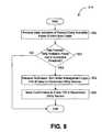
- FIG. 8is a flowchart that depicts exemplary architecture and functionality of the remote meter management logic 314 [ FIG. 3 ].
- the remote meter management logic 314receives data indicative of the FDAP from the collar 103 [ FIG. 1 ]. If the FDAP exceeds or meets a threshold value, as shown in step 901 , the remote meter management logic 314 will receive a notification from meter management logic 214 [ FIG. 7 ]. The remote meter management logic 314 will then send a confirmation to the collar 103 to disconnect the utility service (step 903 ).
- the present inventioncan also be configured in as a wired Ethernet system 910 which has a collar 915 comprising an internal power supply (not shown) capable of supplying both the collar 915 's own power requirements as well as providing a power output 913 capable of supplying a fiber conversion unit 912 and/or its associated backup battery 911 .
- the fiber conversion unit 912is wired with an Ethernet cable 916 to collar 915 .
- the Ethernet fiber from the service provider 917interfaces with the fiber conversion unit 912 .
- This configurationallows the fiber service provider (not shown) to gain the necessary power supply and provide communications for utility based applications from one collar 103 .
- the power supply (not shown) in collar 915can supply power directly to the fiber conversion unit 912 if a battery backup 911 is not utilized.
- the present inventionmay also be in the form of a utility meter 102 with all of the features of the present invention that are described as residing in collar 103 instead incorporated into the utility meter 102 .
- the present inventioncomprises a collar-based system and method for controlling a utility meter. While particular embodiments of the invention have been described, it will be understood, however, that the invention is not limited thereto, since modifications may be made by those skilled in the art, particularly in light of the foregoing teachings. It is, therefore, contemplated by the appended claims to cover any such modifications that incorporate those features or those improvements that embody the spirit and scope of the present invention.
Landscapes
- Business, Economics & Management (AREA)
- Accounting & Taxation (AREA)
- Finance (AREA)
- Engineering & Computer Science (AREA)
- Physics & Mathematics (AREA)
- General Physics & Mathematics (AREA)
- Economics (AREA)
- General Business, Economics & Management (AREA)
- Strategic Management (AREA)
- Development Economics (AREA)
- Theoretical Computer Science (AREA)
- Marketing (AREA)
- Health & Medical Sciences (AREA)
- Public Health (AREA)
- Technology Law (AREA)
- Water Supply & Treatment (AREA)
- General Health & Medical Sciences (AREA)
- Human Resources & Organizations (AREA)
- Primary Health Care (AREA)
- Tourism & Hospitality (AREA)
- Arrangements For Transmission Of Measured Signals (AREA)
- Remote Monitoring And Control Of Power-Distribution Networks (AREA)
Abstract
Description
Claims (33)
Priority Applications (3)
| Application Number | Priority Date | Filing Date | Title |
|---|---|---|---|
| US11/824,131US8140414B2 (en) | 2006-06-29 | 2007-06-29 | System and method for controlling a utility meter |
| US11/955,010US8103563B2 (en) | 2006-06-29 | 2007-12-12 | System and method for monitoring, controlling, and displaying utility information |
| US13/357,581US8407115B2 (en) | 2006-06-29 | 2012-01-24 | System and method for monitoring, controlling, and displaying utility information |
Applications Claiming Priority (2)
| Application Number | Priority Date | Filing Date | Title |
|---|---|---|---|
| US81748706P | 2006-06-29 | 2006-06-29 | |
| US11/824,131US8140414B2 (en) | 2006-06-29 | 2007-06-29 | System and method for controlling a utility meter |
Related Child Applications (1)
| Application Number | Title | Priority Date | Filing Date |
|---|---|---|---|
| US11/955,010Continuation-In-PartUS8103563B2 (en) | 2006-06-29 | 2007-12-12 | System and method for monitoring, controlling, and displaying utility information |
Publications (2)
| Publication Number | Publication Date |
|---|---|
| US20080086394A1 US20080086394A1 (en) | 2008-04-10 |
| US8140414B2true US8140414B2 (en) | 2012-03-20 |
Family
ID=38895145
Family Applications (1)
| Application Number | Title | Priority Date | Filing Date |
|---|---|---|---|
| US11/824,131ActiveUS8140414B2 (en) | 2006-06-29 | 2007-06-29 | System and method for controlling a utility meter |
Country Status (5)
| Country | Link |
|---|---|
| US (1) | US8140414B2 (en) |
| CA (1) | CA2656405A1 (en) |
| GB (1) | GB2453303A (en) |
| MX (1) | MX2009000263A (en) |
| WO (1) | WO2008005359A2 (en) |
Cited By (26)
| Publication number | Priority date | Publication date | Assignee | Title |
|---|---|---|---|---|
| US20120116597A1 (en)* | 2010-11-09 | 2012-05-10 | General Electric Company | Gateway mirroring of metering data between zigbee networks |
| US20130154370A1 (en)* | 2011-12-20 | 2013-06-20 | Kohler Co. | Power management system that includes a generator controller which selectively activates a transfer switch |
| US20150153201A1 (en)* | 2012-01-09 | 2015-06-04 | Movelo Ab | Reporting of meter indication |
| US9151516B2 (en) | 2006-01-27 | 2015-10-06 | Emerson Electric Co. | Smart energy controlled water heater |
| US9188363B2 (en) | 2006-01-27 | 2015-11-17 | Emerson Electric Co. | Smart energy controlled water heater |
| US9310098B2 (en) | 2006-01-27 | 2016-04-12 | Emerson Electric Co. | Water heater control using external temperature sensor |
| US20160182233A1 (en)* | 2014-12-19 | 2016-06-23 | Korea Internet & Security Agency | Power information transmitting and receiving system in smart grid |
| US20160350734A1 (en)* | 2014-06-01 | 2016-12-01 | Gideon Samid | Versatile, Real Time, Two-Ways Payment for Power and Utilities |
| US9535917B1 (en)* | 2012-09-28 | 2017-01-03 | Emc Corporation | Detection of anomalous utility usage |
| US9594098B2 (en) | 2009-09-25 | 2017-03-14 | Belkin International Inc. | Systems and methods for measuring electrical power usage in a structure and systems and methods of calibrating the same |
| US20170141575A1 (en)* | 2015-11-13 | 2017-05-18 | Infinite Invention Llc | Distributed generator automatic provisioning |
| US9762980B2 (en) | 2014-09-26 | 2017-09-12 | Mueller International, Llc | High output integrated utility meter reporting system |
| US9766277B2 (en) | 2009-09-25 | 2017-09-19 | Belkin International, Inc. | Self-calibrating contactless power consumption sensing |
| US9841799B2 (en) | 2011-12-20 | 2017-12-12 | Kohler Co. | System and method for using a network to control a power management system |
| US9857449B2 (en) | 2010-07-02 | 2018-01-02 | Belkin International, Inc. | System and method for monitoring electrical power usage in an electrical power infrastructure of a building |
| US9918145B2 (en) | 2014-09-26 | 2018-03-13 | Mueller International, Llc | High output integrated utility meter reporting system |
| US10193756B2 (en) | 2015-05-12 | 2019-01-29 | The Toronoto-Dominion Bank | Resource allocation based on connected devices |
| US10247765B2 (en) | 2007-09-18 | 2019-04-02 | Georgia Tech Research Corporation | Detecting actuation of electrical devices using electrical noise over a power line |
| US10355955B2 (en) | 2015-05-12 | 2019-07-16 | The Toronto-Dominion Bank | Resource allocation control based on connected devices |
| US20190297395A1 (en)* | 2018-03-24 | 2019-09-26 | Yunteng Huang | Automated meter reading |
| US10693317B2 (en)* | 2016-12-29 | 2020-06-23 | Encored Technologies, Inc. | Server and home appliance having power demand management function and method of managing power usage thereof |
| US10853774B2 (en) | 2015-10-29 | 2020-12-01 | The Toronto-Dominion Bank | Data transfer control based on connected device usage analysis |
| US10878816B2 (en) | 2017-10-04 | 2020-12-29 | The Toronto-Dominion Bank | Persona-based conversational interface personalization using social network preferences |
| US10943605B2 (en) | 2017-10-04 | 2021-03-09 | The Toronto-Dominion Bank | Conversational interface determining lexical personality score for response generation with synonym replacement |
| US11264807B2 (en) | 2019-09-30 | 2022-03-01 | James Arnim White | Renewable energy metering system |
| US11495965B2 (en) | 2016-12-15 | 2022-11-08 | TechSouth Solutions, LLC | Site management systems and methods |
Families Citing this family (25)
| Publication number | Priority date | Publication date | Assignee | Title |
|---|---|---|---|---|
| US8392107B2 (en)* | 2006-06-28 | 2013-03-05 | Georgia Tech Research Corporation | Sub-room-level indoor location system using power line positioning |
| US8494762B2 (en)* | 2006-06-28 | 2013-07-23 | Georgia Tech Research Corporation | Sub room level indoor location system using wideband power line positioning |
| NZ549548A (en)* | 2006-08-31 | 2009-04-30 | Arc Innovations Ltd | Managing supply of a utility to a customer premises |
| US20100039263A1 (en)* | 2008-07-10 | 2010-02-18 | Christopher Way-Fung Chen | System and method for utilization of smart meter infrastructure |
| FR2934053B1 (en)* | 2008-07-18 | 2011-04-29 | Poweo | METHOD AND LUMINOUS DEVICE FOR CONSULTING THE CONSUMPTION OF AN INSTALLATION |
| BRPI1014862A2 (en) | 2009-03-31 | 2016-04-12 | Freestyle Technology Pty Ltd | "communication process and system associated with monitoring and controlling resource consumption" |
| US8886489B2 (en) | 2009-05-12 | 2014-11-11 | Georgia Tech Research Corporation | Motion detecting method and device |
| US8457908B2 (en) | 2009-06-11 | 2013-06-04 | University Of Washington | Sensing events affecting liquid flow in a liquid distribution system |
| US8930152B2 (en)* | 2009-09-25 | 2015-01-06 | University Of Washington | Whole structure contactless power consumption sensing |
| NL2003895C2 (en)* | 2009-12-02 | 2011-06-06 | Supergroen V O F | Self-installable system for management and control of energy consumption. |
| US8788191B1 (en) | 2010-03-18 | 2014-07-22 | Georgia Tech Research Corporation | Method and apparatus for using in-home power lines to support low power wireless sensors and to extend the range of low-power wireless devices |
| AU2011248626B2 (en) | 2010-04-26 | 2014-11-06 | Belkin International, Inc. | Electrical event detection device and method of detecting and classifying electrical power usage |
| CN102540999A (en)* | 2011-01-03 | 2012-07-04 | 湖北盛佳电器设备有限公司 | Intelligent control platform of multimedia water consumption management system |
| US8839101B2 (en)* | 2011-01-07 | 2014-09-16 | General Electric Company | Flexible meter configuration software architecture |
| EP2686643A4 (en) | 2011-03-18 | 2014-09-10 | Soneter Llc | Methods and apparatus for fluid flow measurement |
| US8996144B2 (en) | 2011-10-06 | 2015-03-31 | General Electric Company | Remote disconnect switch assembly |
| US9140576B2 (en)* | 2012-01-23 | 2015-09-22 | General Electric Company | Demand response without Time-of-Use metering |
| CN103454531B (en)* | 2013-09-04 | 2016-05-25 | 四川石棉华瑞电子有限公司 | To the system and method for formed aluminum foil productive power monitoring |
| CN107005314B (en) | 2014-09-04 | 2019-07-30 | 华盛顿大学 | Detects the user-driven operating state of an electronic device from a single sensing point |
| US10352814B2 (en) | 2015-11-10 | 2019-07-16 | Phyn Llc | Water leak detection using pressure sensing |
| WO2017218428A1 (en)* | 2016-06-17 | 2017-12-21 | Water Pigeon Inc. | Systems and methods for automated meter reading |
| US10094095B2 (en) | 2016-11-04 | 2018-10-09 | Phyn, Llc | System and method for leak characterization after shutoff of pressurization source |
| CN107067558B (en)* | 2017-03-14 | 2020-04-17 | 中国电力科学研究院 | Distributed agricultural discharge control system |
| US10527516B2 (en) | 2017-11-20 | 2020-01-07 | Phyn Llc | Passive leak detection for building water supply |
| CN111080912B (en)* | 2019-12-09 | 2021-07-16 | 浙江威星智能仪表股份有限公司 | Internet of things gas meter prepayment logic system and method based on photoelectric direct reading information |
Citations (94)
| Publication number | Priority date | Publication date | Assignee | Title |
|---|---|---|---|---|
| US4023043A (en) | 1974-08-16 | 1977-05-10 | Megatherm Corporation | Computerized peak-shaving system for alleviating electric utility peak loads |
| US4419667A (en) | 1979-07-02 | 1983-12-06 | Sangamo Weston, Inc. | System for controlling power distribution to customer loads |
| US4482964A (en)* | 1980-03-10 | 1984-11-13 | Exxon Research And Engineering Co. | Fluid register system |
| US4587417A (en) | 1982-06-10 | 1986-05-06 | Area Lighting Research, Inc. | Field-adjustable power control arrangement and methods of controlling power and of adjusting the timing thereof |
| US4766331A (en) | 1987-09-18 | 1988-08-23 | Reliance Time Controls, Inc. | Timer switch with auxiliary actuator |
| US4804957A (en)* | 1985-11-27 | 1989-02-14 | Triad Communications, Inc. | Utility meter and submetering system |
| US4940976A (en)* | 1988-02-05 | 1990-07-10 | Utilicom Inc. | Automated remote water meter readout system |
| US5214793A (en) | 1991-03-15 | 1993-05-25 | Pulse-Com Corporation | Electronic billboard and vehicle traffic control communication system |
| US5214587A (en)* | 1990-11-28 | 1993-05-25 | Green Richard G | Device for monitoring utility usage |
| US5381462A (en)* | 1992-05-29 | 1995-01-10 | Datran Systems Corporation | Utility monitor communications systems |
| US5502339A (en) | 1989-09-07 | 1996-03-26 | The Trustees Of Boston University | Subscriber electric power load control system |
| US5684965A (en)* | 1992-10-22 | 1997-11-04 | American Express Travel Related Services, Inc. | Automated billing consolidation system and method |
| US5696695A (en) | 1995-01-05 | 1997-12-09 | Tecom Inc. | System for rate-related control of electrical loads |
| US5699276A (en)* | 1995-12-15 | 1997-12-16 | Roos; Charles E. | Utility meter providing an interface between a digital network and home electronics |
| US5767790A (en)* | 1996-03-07 | 1998-06-16 | Jovellana; Bartolome D. | Automatic utility meter monitor |
| US5897607A (en)* | 1997-02-28 | 1999-04-27 | Jenney Systems Associates, Ltd. | Automatic meter reading system |
| US5968393A (en) | 1995-09-12 | 1999-10-19 | Demaline; John Tracey | Hot water controller |
| US5995601A (en)* | 1998-09-30 | 1999-11-30 | Lucent Technologies, Inc. | Automatic remote meter reading system and method employing selectable line interface |
| US6043642A (en)* | 1996-08-01 | 2000-03-28 | Siemens Power Transmission & Distribution, Inc. | Watt-hour meter with communication on diagnostic error detection |
| US6067052A (en)* | 1998-09-18 | 2000-05-23 | Lucent Technologies Inc. | Loop antenna configuration for printed wire board applications |
| US6124800A (en) | 1996-08-21 | 2000-09-26 | Intermec Ip Corp. | Radio-frequency LAN and WAN communication system for route delivery applications or the like |
| US6208266B1 (en)* | 1995-08-23 | 2001-03-27 | Scientific Telemetry Corporation | Remote data acquisition and processing system |
| US6265699B1 (en) | 2000-05-24 | 2001-07-24 | American Water Heater Company | Water heater with electronic control |
| US6293471B1 (en) | 2000-04-27 | 2001-09-25 | Daniel R. Stettin | Heater control device and method to save energy |
| US20010051933A1 (en)* | 2000-06-08 | 2001-12-13 | Rowley Robert H. | Prepaid utility service system |
| US6350967B1 (en) | 2000-05-24 | 2002-02-26 | American Water Heater Company | Energy saving water heater control |
| US20020040355A1 (en)* | 2000-10-02 | 2002-04-04 | Weiner Steven D. | System and method for utility meter swipecard |
| US6375087B1 (en) | 2000-06-14 | 2002-04-23 | International Business Machines Corporation | Method and apparatus for self-programmable temperature and usage control for hot water heaters |
| US6424270B1 (en)* | 1998-10-30 | 2002-07-23 | Schlumberger Resource Management Services, Inc. | Utility meter interface unit |
| US6465764B1 (en) | 2000-08-30 | 2002-10-15 | State Industries, Inc. | Water heater and control system therefor |
| US20030009401A1 (en)* | 2001-04-27 | 2003-01-09 | Enerwise Global Technologies, Inc. | Computerized utility cost estimation method and system |
| US6560409B2 (en) | 2000-01-03 | 2003-05-06 | Honeywell International Inc. | Hot water heater stacking reduction control |
| US20030156041A1 (en)* | 2002-02-18 | 2003-08-21 | Taisto Gregory T. | Method of obtaining a reading of a utility meter |
| US6649881B2 (en) | 1998-06-04 | 2003-11-18 | American Water Heater Company | Electric water heater with pulsed electronic control and detection |
| US20030225713A1 (en)* | 2002-03-08 | 2003-12-04 | Atkinson Roger F. | Prepayment system for power distribution using RFID technology |
| US20040075343A1 (en) | 2002-09-05 | 2004-04-22 | Paul Wareham | System and method for power load management |
| US6737983B1 (en) | 1999-10-26 | 2004-05-18 | John Temple | Display board having illuminated elements and method |
| US20040117330A1 (en) | 2002-03-28 | 2004-06-17 | Ehlers Gregory A. | System and method for controlling usage of a commodity |
| US6785466B1 (en) | 2003-09-22 | 2004-08-31 | Rheem Manufacturing Company | Electric water heater having balanced wattage density water heating |
| US6795644B2 (en) | 1999-07-27 | 2004-09-21 | Kenneth A. Bradenbaugh | Water heater |
| US6819292B2 (en)* | 2001-03-09 | 2004-11-16 | Arad Measuring Technologies Ltd | Meter register |
| US20040243524A1 (en)* | 2003-06-02 | 2004-12-02 | Crichlow Henry B. | System and method for real time generating, presenting, displaying and paying utility bills online |
| US20050021393A1 (en) | 2001-06-12 | 2005-01-27 | Xiaoming Bao | Smart interactive billboard device |
| US6859742B2 (en)* | 2001-07-12 | 2005-02-22 | Landis+Gyr Inc. | Redundant precision time keeping for utility meters |
| US20050083210A1 (en)* | 2002-06-27 | 2005-04-21 | Shuey Kenneth C. | Dynamic self-configuring metering network |
| US6957058B2 (en)* | 2000-12-18 | 2005-10-18 | Sbc Technology Resources, Inc. | Prepaid wireless telephone account regeneration in a wireless access protocol system |
| US6955301B2 (en) | 2003-03-05 | 2005-10-18 | Honeywell International, Inc. | Water heater and control |
| US6961641B1 (en) | 1994-12-30 | 2005-11-01 | Power Measurement Ltd. | Intra-device communications architecture for managing electrical power distribution and consumption |
| US20050246295A1 (en)* | 2004-04-08 | 2005-11-03 | Cameron Richard N | Method and system for remotely monitoring meters |
| US6965303B2 (en) | 2002-12-10 | 2005-11-15 | Current Technologies, Llc | Power line communication system and method |
| US6980973B1 (en)* | 1999-09-07 | 2005-12-27 | Visa International Service Association | Self-paying smart utility meter and payment service |
| US6989514B2 (en) | 2002-10-11 | 2006-01-24 | Synapse, Inc. | System and method for controlling temperature control elements that are used to alter liquid temperature |
| US6993417B2 (en) | 2001-09-10 | 2006-01-31 | Osann Jr Robert | System for energy sensing analysis and feedback |
| US20060031180A1 (en) | 2004-08-03 | 2006-02-09 | Uscl Corporation | Integrated metrology systems and information and control apparatus for interaction with integrated metrology systems |
| US7010363B2 (en) | 2003-06-13 | 2006-03-07 | Battelle Memorial Institute | Electrical appliance energy consumption control methods and electrical energy consumption systems |
| US20060069661A1 (en)* | 2004-09-24 | 2006-03-30 | Scoggins Sean M | System and method for automated configuration of meters |
| US7043459B2 (en)* | 1997-12-19 | 2006-05-09 | Constellation Energy Group, Inc. | Method and apparatus for metering electricity usage and electronically providing information associated therewith |
| US20060106741A1 (en)* | 2004-11-17 | 2006-05-18 | San Vision Energy Technology Inc. | Utility monitoring system and method for relaying personalized real-time utility consumption information to a consumer |
| US20060129498A1 (en)* | 2001-01-17 | 2006-06-15 | Smart Disaster Response Technologies, Inc. | Methods, apparatus, media, and signals for monitoring utility usage |
| US7065431B2 (en) | 2001-11-15 | 2006-06-20 | Synapse, Inc. | System and method for controlling temperature of a liquid residing within a tank |
| US7064679B2 (en)* | 1997-09-05 | 2006-06-20 | Silver Spring Networks, Inc. | Electronic electric meter for networked meter reading |
| US7075414B2 (en) | 2003-05-13 | 2006-07-11 | Current Technologies, Llc | Device and method for communicating data signals through multiple power line conductors |
| US7117825B2 (en) | 2004-06-30 | 2006-10-10 | Synapse, Inc. | System and method for preventing overheating of water within a water heater tank |
| US7230544B2 (en)* | 2002-04-22 | 2007-06-12 | Cellnet Innovations, Inc. | Intelligent two-way telemetry |
| US20070203860A1 (en)* | 2006-02-24 | 2007-08-30 | Gridpoint, Inc. | Energy budget manager |
| US20070205915A1 (en) | 2006-02-16 | 2007-09-06 | Elster Electricty, Llc | Load control unit in communication with a fixed network meter reading system |
| US7274305B1 (en) | 2002-10-16 | 2007-09-25 | Carina Technology, Inc. | Electrical utility communications and control system |
| US20070255612A1 (en)* | 2006-04-28 | 2007-11-01 | Baraty Mohammad R | Methods, apparatus, media and signals for facilitating real-time management of a utility supply |
| US7310052B2 (en)* | 2005-07-06 | 2007-12-18 | Bowman Eric L | Wireless meter-reading system and methods thereof |
| US7336200B2 (en)* | 2003-09-05 | 2008-02-26 | Itron, Inc. | Data communication protocol in an automatic meter reading system |
| US20080052253A1 (en)* | 2006-08-28 | 2008-02-28 | Emeter Corporation | System and method for message-bus-based advanced meter information system |
| US20080048883A1 (en)* | 2003-02-14 | 2008-02-28 | Energy Technology Group, Inc. | Methods of performing automated meter reading and processing meter data |
| US20080129538A1 (en)* | 1999-02-23 | 2008-06-05 | Raj Vaswani | Electronic electric meter for networked meter reading |
| US20080133065A1 (en) | 2003-08-20 | 2008-06-05 | Cannon Technologies, Inc. | Utility load control management communications protocol |
| US20080177678A1 (en)* | 2007-01-24 | 2008-07-24 | Paul Di Martini | Method of communicating between a utility and its customer locations |
| US20080191695A1 (en)* | 2005-03-31 | 2008-08-14 | Koninklijke Philips Electronics N. V. | Mri System Comprising a Scan Room Inferface for A/D-Conversion of Mr Signals Between a Receiver Coil Unit and a Remote Signal Processing Unit |
| US20080238710A1 (en) | 2007-03-23 | 2008-10-02 | Jeff Tolnar | system and method for demand dispatch and load management |
| US7432477B2 (en) | 2005-04-19 | 2008-10-07 | Robert Teti | Set-back control for both HVAC and water heater via a single programmable thermostat |
| US7432823B2 (en)* | 2005-11-09 | 2008-10-07 | Distribution Control Systems, Inc. | Tamper detection apparatus for electrical meters |
| US7453373B2 (en)* | 2004-10-29 | 2008-11-18 | Itron, Inc. | Integrated meter module and utility metering system |
| US7503287B2 (en) | 2003-10-20 | 2009-03-17 | Bunn-O-Matic Corporation | System, method and apparatus for heating water |
| US20090091472A1 (en)* | 2002-10-30 | 2009-04-09 | Mark Ocondi | Intelligent wireless multicast network |
| US20090105888A1 (en) | 2007-11-08 | 2009-04-23 | Sequentric Energy Systems, Llc | Methods, circuits, and computer program products for generation following load management |
| US7525423B2 (en)* | 2000-04-14 | 2009-04-28 | Current Technologies, Llc | Automated meter reading communication system and method |
| US20090157488A1 (en)* | 2007-12-12 | 2009-06-18 | Carina Technology, Inc. | Work order management system and method |
| US20090210293A1 (en)* | 2000-08-04 | 2009-08-20 | Nick Steele | Information transactions over a network |
| US20090326725A1 (en)* | 2008-05-19 | 2009-12-31 | Michael James Carlson | Managing Electric Power Consumption |
| US20100145837A1 (en)* | 2008-12-05 | 2010-06-10 | Lava Four, Llc | Network for authentication, authorization, and accounting of recharging processes for vehicles equipped with electrically powered propulsion systems |
| US20100174667A1 (en)* | 2009-01-06 | 2010-07-08 | Gm Global Technology Operations, Inc. | Charging cable with controller |
| US20100174668A1 (en)* | 2008-09-15 | 2010-07-08 | General Electric Company | Energy management of clothes dryer appliance |
| US20100306033A1 (en)* | 2009-06-01 | 2010-12-02 | Dror Oved | Electrical power metering and billing network |
| US20110119166A1 (en)* | 2009-11-16 | 2011-05-19 | Leon Steinberg | System and method for renewable energy generation |
| US7999696B2 (en)* | 2004-10-20 | 2011-08-16 | Electro Industries/Gauge Tech | On-line web accessed energy meter |
| US8013732B2 (en)* | 1998-06-22 | 2011-09-06 | Sipco, Llc | Systems and methods for monitoring and controlling remote devices |
- 2007
- 2007-06-29CACA002656405Apatent/CA2656405A1/ennot_activeAbandoned
- 2007-06-29USUS11/824,131patent/US8140414B2/enactiveActive
- 2007-06-29WOPCT/US2007/015178patent/WO2008005359A2/enactiveApplication Filing
- 2007-06-29GBGB0901368Apatent/GB2453303A/ennot_activeWithdrawn
- 2007-06-29MXMX2009000263Apatent/MX2009000263A/enunknown
Patent Citations (98)
| Publication number | Priority date | Publication date | Assignee | Title |
|---|---|---|---|---|
| US4023043A (en) | 1974-08-16 | 1977-05-10 | Megatherm Corporation | Computerized peak-shaving system for alleviating electric utility peak loads |
| US4419667A (en) | 1979-07-02 | 1983-12-06 | Sangamo Weston, Inc. | System for controlling power distribution to customer loads |
| US4482964A (en)* | 1980-03-10 | 1984-11-13 | Exxon Research And Engineering Co. | Fluid register system |
| US4587417A (en) | 1982-06-10 | 1986-05-06 | Area Lighting Research, Inc. | Field-adjustable power control arrangement and methods of controlling power and of adjusting the timing thereof |
| US4804957A (en)* | 1985-11-27 | 1989-02-14 | Triad Communications, Inc. | Utility meter and submetering system |
| US4766331A (en) | 1987-09-18 | 1988-08-23 | Reliance Time Controls, Inc. | Timer switch with auxiliary actuator |
| US4940976A (en)* | 1988-02-05 | 1990-07-10 | Utilicom Inc. | Automated remote water meter readout system |
| US5502339A (en) | 1989-09-07 | 1996-03-26 | The Trustees Of Boston University | Subscriber electric power load control system |
| US5214587A (en)* | 1990-11-28 | 1993-05-25 | Green Richard G | Device for monitoring utility usage |
| US5214793A (en) | 1991-03-15 | 1993-05-25 | Pulse-Com Corporation | Electronic billboard and vehicle traffic control communication system |
| US5381462A (en)* | 1992-05-29 | 1995-01-10 | Datran Systems Corporation | Utility monitor communications systems |
| US5684965A (en)* | 1992-10-22 | 1997-11-04 | American Express Travel Related Services, Inc. | Automated billing consolidation system and method |
| US6961641B1 (en) | 1994-12-30 | 2005-11-01 | Power Measurement Ltd. | Intra-device communications architecture for managing electrical power distribution and consumption |
| US5696695A (en) | 1995-01-05 | 1997-12-09 | Tecom Inc. | System for rate-related control of electrical loads |
| US6208266B1 (en)* | 1995-08-23 | 2001-03-27 | Scientific Telemetry Corporation | Remote data acquisition and processing system |
| US5968393A (en) | 1995-09-12 | 1999-10-19 | Demaline; John Tracey | Hot water controller |
| US5699276A (en)* | 1995-12-15 | 1997-12-16 | Roos; Charles E. | Utility meter providing an interface between a digital network and home electronics |
| US5767790A (en)* | 1996-03-07 | 1998-06-16 | Jovellana; Bartolome D. | Automatic utility meter monitor |
| US6043642A (en)* | 1996-08-01 | 2000-03-28 | Siemens Power Transmission & Distribution, Inc. | Watt-hour meter with communication on diagnostic error detection |
| US6124800A (en) | 1996-08-21 | 2000-09-26 | Intermec Ip Corp. | Radio-frequency LAN and WAN communication system for route delivery applications or the like |
| US5897607A (en)* | 1997-02-28 | 1999-04-27 | Jenney Systems Associates, Ltd. | Automatic meter reading system |
| US7064679B2 (en)* | 1997-09-05 | 2006-06-20 | Silver Spring Networks, Inc. | Electronic electric meter for networked meter reading |
| US7043459B2 (en)* | 1997-12-19 | 2006-05-09 | Constellation Energy Group, Inc. | Method and apparatus for metering electricity usage and electronically providing information associated therewith |
| US6649881B2 (en) | 1998-06-04 | 2003-11-18 | American Water Heater Company | Electric water heater with pulsed electronic control and detection |
| US8013732B2 (en)* | 1998-06-22 | 2011-09-06 | Sipco, Llc | Systems and methods for monitoring and controlling remote devices |
| US6067052A (en)* | 1998-09-18 | 2000-05-23 | Lucent Technologies Inc. | Loop antenna configuration for printed wire board applications |
| US5995601A (en)* | 1998-09-30 | 1999-11-30 | Lucent Technologies, Inc. | Automatic remote meter reading system and method employing selectable line interface |
| US6424270B1 (en)* | 1998-10-30 | 2002-07-23 | Schlumberger Resource Management Services, Inc. | Utility meter interface unit |
| US7772989B2 (en)* | 1999-02-23 | 2010-08-10 | Silver Spring Networks, Inc. | Electronic electric meter for networked meter reading |
| US20080129538A1 (en)* | 1999-02-23 | 2008-06-05 | Raj Vaswani | Electronic electric meter for networked meter reading |
| US6795644B2 (en) | 1999-07-27 | 2004-09-21 | Kenneth A. Bradenbaugh | Water heater |
| US6980973B1 (en)* | 1999-09-07 | 2005-12-27 | Visa International Service Association | Self-paying smart utility meter and payment service |
| US6737983B1 (en) | 1999-10-26 | 2004-05-18 | John Temple | Display board having illuminated elements and method |
| US6560409B2 (en) | 2000-01-03 | 2003-05-06 | Honeywell International Inc. | Hot water heater stacking reduction control |
| US7525423B2 (en)* | 2000-04-14 | 2009-04-28 | Current Technologies, Llc | Automated meter reading communication system and method |
| US6293471B1 (en) | 2000-04-27 | 2001-09-25 | Daniel R. Stettin | Heater control device and method to save energy |
| US6350967B1 (en) | 2000-05-24 | 2002-02-26 | American Water Heater Company | Energy saving water heater control |
| US6265699B1 (en) | 2000-05-24 | 2001-07-24 | American Water Heater Company | Water heater with electronic control |
| US20010051933A1 (en)* | 2000-06-08 | 2001-12-13 | Rowley Robert H. | Prepaid utility service system |
| US6375087B1 (en) | 2000-06-14 | 2002-04-23 | International Business Machines Corporation | Method and apparatus for self-programmable temperature and usage control for hot water heaters |
| US20090210293A1 (en)* | 2000-08-04 | 2009-08-20 | Nick Steele | Information transactions over a network |
| US6465764B1 (en) | 2000-08-30 | 2002-10-15 | State Industries, Inc. | Water heater and control system therefor |
| US20020040355A1 (en)* | 2000-10-02 | 2002-04-04 | Weiner Steven D. | System and method for utility meter swipecard |
| US6957058B2 (en)* | 2000-12-18 | 2005-10-18 | Sbc Technology Resources, Inc. | Prepaid wireless telephone account regeneration in a wireless access protocol system |
| US20060129498A1 (en)* | 2001-01-17 | 2006-06-15 | Smart Disaster Response Technologies, Inc. | Methods, apparatus, media, and signals for monitoring utility usage |
| US6819292B2 (en)* | 2001-03-09 | 2004-11-16 | Arad Measuring Technologies Ltd | Meter register |
| US20030009401A1 (en)* | 2001-04-27 | 2003-01-09 | Enerwise Global Technologies, Inc. | Computerized utility cost estimation method and system |
| US20050021393A1 (en) | 2001-06-12 | 2005-01-27 | Xiaoming Bao | Smart interactive billboard device |
| US6859742B2 (en)* | 2001-07-12 | 2005-02-22 | Landis+Gyr Inc. | Redundant precision time keeping for utility meters |
| US6993417B2 (en) | 2001-09-10 | 2006-01-31 | Osann Jr Robert | System for energy sensing analysis and feedback |
| US7065431B2 (en) | 2001-11-15 | 2006-06-20 | Synapse, Inc. | System and method for controlling temperature of a liquid residing within a tank |
| US20030156041A1 (en)* | 2002-02-18 | 2003-08-21 | Taisto Gregory T. | Method of obtaining a reading of a utility meter |
| US20030225713A1 (en)* | 2002-03-08 | 2003-12-04 | Atkinson Roger F. | Prepayment system for power distribution using RFID technology |
| US20040117330A1 (en) | 2002-03-28 | 2004-06-17 | Ehlers Gregory A. | System and method for controlling usage of a commodity |
| US20040139038A1 (en)* | 2002-03-28 | 2004-07-15 | Ehlers Gregory A. | System and method for controlling delivering of a commodity |
| US7230544B2 (en)* | 2002-04-22 | 2007-06-12 | Cellnet Innovations, Inc. | Intelligent two-way telemetry |
| US20050083210A1 (en)* | 2002-06-27 | 2005-04-21 | Shuey Kenneth C. | Dynamic self-configuring metering network |
| US20040075343A1 (en) | 2002-09-05 | 2004-04-22 | Paul Wareham | System and method for power load management |
| US6989514B2 (en) | 2002-10-11 | 2006-01-24 | Synapse, Inc. | System and method for controlling temperature control elements that are used to alter liquid temperature |
| US7274305B1 (en) | 2002-10-16 | 2007-09-25 | Carina Technology, Inc. | Electrical utility communications and control system |
| US20090091472A1 (en)* | 2002-10-30 | 2009-04-09 | Mark Ocondi | Intelligent wireless multicast network |
| US6965303B2 (en) | 2002-12-10 | 2005-11-15 | Current Technologies, Llc | Power line communication system and method |
| US20080048883A1 (en)* | 2003-02-14 | 2008-02-28 | Energy Technology Group, Inc. | Methods of performing automated meter reading and processing meter data |
| US6955301B2 (en) | 2003-03-05 | 2005-10-18 | Honeywell International, Inc. | Water heater and control |
| US7075414B2 (en) | 2003-05-13 | 2006-07-11 | Current Technologies, Llc | Device and method for communicating data signals through multiple power line conductors |
| US7098783B2 (en)* | 2003-06-02 | 2006-08-29 | Crichlow Henry B | System and method for real time generating, presenting, displaying and paying utility bills online |
| US20040243524A1 (en)* | 2003-06-02 | 2004-12-02 | Crichlow Henry B. | System and method for real time generating, presenting, displaying and paying utility bills online |
| US7010363B2 (en) | 2003-06-13 | 2006-03-07 | Battelle Memorial Institute | Electrical appliance energy consumption control methods and electrical energy consumption systems |
| US20080133065A1 (en) | 2003-08-20 | 2008-06-05 | Cannon Technologies, Inc. | Utility load control management communications protocol |
| US7336200B2 (en)* | 2003-09-05 | 2008-02-26 | Itron, Inc. | Data communication protocol in an automatic meter reading system |
| US6785466B1 (en) | 2003-09-22 | 2004-08-31 | Rheem Manufacturing Company | Electric water heater having balanced wattage density water heating |
| US7503287B2 (en) | 2003-10-20 | 2009-03-17 | Bunn-O-Matic Corporation | System, method and apparatus for heating water |
| US20050246295A1 (en)* | 2004-04-08 | 2005-11-03 | Cameron Richard N | Method and system for remotely monitoring meters |
| US7117825B2 (en) | 2004-06-30 | 2006-10-10 | Synapse, Inc. | System and method for preventing overheating of water within a water heater tank |
| US20060031180A1 (en) | 2004-08-03 | 2006-02-09 | Uscl Corporation | Integrated metrology systems and information and control apparatus for interaction with integrated metrology systems |
| US20060069661A1 (en)* | 2004-09-24 | 2006-03-30 | Scoggins Sean M | System and method for automated configuration of meters |
| US7999696B2 (en)* | 2004-10-20 | 2011-08-16 | Electro Industries/Gauge Tech | On-line web accessed energy meter |
| US7453373B2 (en)* | 2004-10-29 | 2008-11-18 | Itron, Inc. | Integrated meter module and utility metering system |
| US20060106741A1 (en)* | 2004-11-17 | 2006-05-18 | San Vision Energy Technology Inc. | Utility monitoring system and method for relaying personalized real-time utility consumption information to a consumer |
| US7746072B2 (en)* | 2005-03-31 | 2010-06-29 | Koninklijke Philips Electronics N.V. | MRI system comprising a scan room interface for A/D-conversion of MR signals between a receiver coil unit and a remote signal processing unit |
| US20080191695A1 (en)* | 2005-03-31 | 2008-08-14 | Koninklijke Philips Electronics N. V. | Mri System Comprising a Scan Room Inferface for A/D-Conversion of Mr Signals Between a Receiver Coil Unit and a Remote Signal Processing Unit |
| US7432477B2 (en) | 2005-04-19 | 2008-10-07 | Robert Teti | Set-back control for both HVAC and water heater via a single programmable thermostat |
| US7310052B2 (en)* | 2005-07-06 | 2007-12-18 | Bowman Eric L | Wireless meter-reading system and methods thereof |
| US7432823B2 (en)* | 2005-11-09 | 2008-10-07 | Distribution Control Systems, Inc. | Tamper detection apparatus for electrical meters |
| US20070205915A1 (en) | 2006-02-16 | 2007-09-06 | Elster Electricty, Llc | Load control unit in communication with a fixed network meter reading system |
| US20070203860A1 (en)* | 2006-02-24 | 2007-08-30 | Gridpoint, Inc. | Energy budget manager |
| US20070255612A1 (en)* | 2006-04-28 | 2007-11-01 | Baraty Mohammad R | Methods, apparatus, media and signals for facilitating real-time management of a utility supply |
| US20080052253A1 (en)* | 2006-08-28 | 2008-02-28 | Emeter Corporation | System and method for message-bus-based advanced meter information system |
| US20080177678A1 (en)* | 2007-01-24 | 2008-07-24 | Paul Di Martini | Method of communicating between a utility and its customer locations |
| US20080238710A1 (en) | 2007-03-23 | 2008-10-02 | Jeff Tolnar | system and method for demand dispatch and load management |
| US20090105888A1 (en) | 2007-11-08 | 2009-04-23 | Sequentric Energy Systems, Llc | Methods, circuits, and computer program products for generation following load management |
| US20090157488A1 (en)* | 2007-12-12 | 2009-06-18 | Carina Technology, Inc. | Work order management system and method |
| US20090326725A1 (en)* | 2008-05-19 | 2009-12-31 | Michael James Carlson | Managing Electric Power Consumption |
| US20100174668A1 (en)* | 2008-09-15 | 2010-07-08 | General Electric Company | Energy management of clothes dryer appliance |
| US20100145837A1 (en)* | 2008-12-05 | 2010-06-10 | Lava Four, Llc | Network for authentication, authorization, and accounting of recharging processes for vehicles equipped with electrically powered propulsion systems |
| US20100174667A1 (en)* | 2009-01-06 | 2010-07-08 | Gm Global Technology Operations, Inc. | Charging cable with controller |
| US20100306033A1 (en)* | 2009-06-01 | 2010-12-02 | Dror Oved | Electrical power metering and billing network |
| US20110119166A1 (en)* | 2009-11-16 | 2011-05-19 | Leon Steinberg | System and method for renewable energy generation |
Non-Patent Citations (4)
| Title |
|---|
| Competitive edge PowerView by Coleman Andrew, V131 N20, pp. 40-43, Nov. 1, 1993.* |
| Correcting and Replacing FPL, Business wire, p. 5324, Jul. 7, 2003.* |
| ONT powering options abound; Meghan Fuller, Lightwave, Tulsa Mar. 2006 vol. 23, Iss 3 pp. 17 2 pgs.* |
| Pepco Technologies keeps power on; Transmission & Distribution World Overland Park, May 2000, vol. 52, Iss 5; p. 18 1 pgs.* |
Cited By (37)
| Publication number | Priority date | Publication date | Assignee | Title |
|---|---|---|---|---|
| US9151516B2 (en) | 2006-01-27 | 2015-10-06 | Emerson Electric Co. | Smart energy controlled water heater |
| US9188363B2 (en) | 2006-01-27 | 2015-11-17 | Emerson Electric Co. | Smart energy controlled water heater |
| US9310098B2 (en) | 2006-01-27 | 2016-04-12 | Emerson Electric Co. | Water heater control using external temperature sensor |
| US9752798B2 (en) | 2006-01-27 | 2017-09-05 | Emerson Electric Co. | Water heater control using external temperature sensor |
| US9605872B2 (en) | 2006-01-27 | 2017-03-28 | Emerson Electric Co. | Smart energy controlled water heater |
| US11119141B2 (en) | 2007-09-18 | 2021-09-14 | Georgia Tech Research Corporation | Detecting actuation of electrical devices using electrical noise over a power line |
| US10247765B2 (en) | 2007-09-18 | 2019-04-02 | Georgia Tech Research Corporation | Detecting actuation of electrical devices using electrical noise over a power line |
| US9594098B2 (en) | 2009-09-25 | 2017-03-14 | Belkin International Inc. | Systems and methods for measuring electrical power usage in a structure and systems and methods of calibrating the same |
| US10371728B2 (en) | 2009-09-25 | 2019-08-06 | Belkin International, Inc. | Self-calibrating contactless power consumption sensing |
| US9766277B2 (en) | 2009-09-25 | 2017-09-19 | Belkin International, Inc. | Self-calibrating contactless power consumption sensing |
| US10459012B2 (en) | 2010-07-02 | 2019-10-29 | Belkin International, Inc. | System for monitoring electrical power usage of a structure and method of same |
| US10345423B2 (en) | 2010-07-02 | 2019-07-09 | Belkin International Inc. | System and method for monitoring electrical power usage in an electrical power infrastructure of a building |
| US9857449B2 (en) | 2010-07-02 | 2018-01-02 | Belkin International, Inc. | System and method for monitoring electrical power usage in an electrical power infrastructure of a building |
| US8718798B2 (en)* | 2010-11-09 | 2014-05-06 | General Electric Company | Gateway mirroring of metering data between zigbee networks |
| US20120116597A1 (en)* | 2010-11-09 | 2012-05-10 | General Electric Company | Gateway mirroring of metering data between zigbee networks |
| US9841799B2 (en) | 2011-12-20 | 2017-12-12 | Kohler Co. | System and method for using a network to control a power management system |
| US9281716B2 (en)* | 2011-12-20 | 2016-03-08 | Kohler Co. | Generator controller configured for preventing automatic transfer switch from supplying power to the selected load |
| US20130154370A1 (en)* | 2011-12-20 | 2013-06-20 | Kohler Co. | Power management system that includes a generator controller which selectively activates a transfer switch |
| US20150153201A1 (en)* | 2012-01-09 | 2015-06-04 | Movelo Ab | Reporting of meter indication |
| US9535917B1 (en)* | 2012-09-28 | 2017-01-03 | Emc Corporation | Detection of anomalous utility usage |
| US20160350734A1 (en)* | 2014-06-01 | 2016-12-01 | Gideon Samid | Versatile, Real Time, Two-Ways Payment for Power and Utilities |
| US9762980B2 (en) | 2014-09-26 | 2017-09-12 | Mueller International, Llc | High output integrated utility meter reporting system |
| US9918145B2 (en) | 2014-09-26 | 2018-03-13 | Mueller International, Llc | High output integrated utility meter reporting system |
| US20160182233A1 (en)* | 2014-12-19 | 2016-06-23 | Korea Internet & Security Agency | Power information transmitting and receiving system in smart grid |
| US10355955B2 (en) | 2015-05-12 | 2019-07-16 | The Toronto-Dominion Bank | Resource allocation control based on connected devices |
| US10193756B2 (en) | 2015-05-12 | 2019-01-29 | The Toronoto-Dominion Bank | Resource allocation based on connected devices |
| US10938700B2 (en) | 2015-05-12 | 2021-03-02 | The Toronto-Dominion Bank | Resource allocation control based on connected devices |
| US11108667B2 (en) | 2015-05-12 | 2021-08-31 | The Toronto-Dominion Bank | Resource allocation control based on connected devices |
| US10853774B2 (en) | 2015-10-29 | 2020-12-01 | The Toronto-Dominion Bank | Data transfer control based on connected device usage analysis |
| US10431986B2 (en)* | 2015-11-13 | 2019-10-01 | Infinite Invention Inc. | Distributed generator automatic provisioning |
| US20170141575A1 (en)* | 2015-11-13 | 2017-05-18 | Infinite Invention Llc | Distributed generator automatic provisioning |
| US11495965B2 (en) | 2016-12-15 | 2022-11-08 | TechSouth Solutions, LLC | Site management systems and methods |
| US10693317B2 (en)* | 2016-12-29 | 2020-06-23 | Encored Technologies, Inc. | Server and home appliance having power demand management function and method of managing power usage thereof |
| US10878816B2 (en) | 2017-10-04 | 2020-12-29 | The Toronto-Dominion Bank | Persona-based conversational interface personalization using social network preferences |
| US10943605B2 (en) | 2017-10-04 | 2021-03-09 | The Toronto-Dominion Bank | Conversational interface determining lexical personality score for response generation with synonym replacement |
| US20190297395A1 (en)* | 2018-03-24 | 2019-09-26 | Yunteng Huang | Automated meter reading |
| US11264807B2 (en) | 2019-09-30 | 2022-03-01 | James Arnim White | Renewable energy metering system |
Also Published As
| Publication number | Publication date |
|---|---|
| MX2009000263A (en) | 2009-04-15 |
| US20080086394A1 (en) | 2008-04-10 |
| CA2656405A1 (en) | 2008-01-10 |
| WO2008005359A3 (en) | 2008-10-16 |
| GB2453303A (en) | 2009-04-01 |
| WO2008005359A2 (en) | 2008-01-10 |
| GB0901368D0 (en) | 2009-03-11 |
Similar Documents
| Publication | Publication Date | Title |
|---|---|---|
| US8140414B2 (en) | System and method for controlling a utility meter | |
| US8103563B2 (en) | System and method for monitoring, controlling, and displaying utility information | |
| US8639390B2 (en) | Integrated metrology systems and information and control apparatus for interaction with integrated metrology system | |
| EP2096416B1 (en) | Management platform and associated method for managing smart meters | |
| CN105260885A (en) | Internet of things mobile phone APP self-service prepayment and cloud management system | |
| US20120166233A1 (en) | Method And Apparatus For Enhancing Consumer Awareness Of Utility Consumption And Cost Data | |
| CN105867274B (en) | Electric control system and method are connect based on remote bill control, the anti-intelligent residential district dress table visited one house after another | |
| WO2010132469A2 (en) | System and method for selective disconnection of electrical service to end customers | |
| CN204214498U (en) | A kind of combustible gas metering arrangement | |
| KR102429289B1 (en) | Autonomous integrated remote meter reading and fare notification system | |
| JP3202005B2 (en) | Automatic meter reading system for electric power | |
| Kaliappan et al. | IOT Based Smart Prepaid Energy Recharge Scheme for EB | |
| Bhakthavathsalam et al. | Zigbee based energy monitoring system with e-billing through GSM network | |
| CN105551225A (en) | Electric power remote meter reading system | |
| Gliwan et al. | Remotely Controlled Single-Phase Electric Meter Supporting Different Tariffs | |
| Deepika et al. | IoT based prepaid electricity | |
| Julihi et al. | Wireless home energy meter manager using android: a preliminary study | |
| Amutha et al. | Smart Energy Meter Using GSM for Home Automation | |
| JP2017077059A (en) | Notification system | |
| Students | A Review on Digital Energy Management Systems | |
| CN115131915A (en) | Visual electric power marketing service terminal equipment and implementation method thereof | |
| GB2456125A (en) | Electricity supply monitoring apparatus | |
| Gopichand et al. | AUTOMATION OF ELECTRICITY BILL GENERATION BASED ON IOT | |
| GB2435732A (en) | A utility metering system incorporating a private / public radio network | |
| Mandlik et al. | Design of an intelligent SMS based remote metering system |
Legal Events
| Date | Code | Title | Description |
|---|---|---|---|
| AS | Assignment | Owner name:CARINA TECHNOLOGY, INC.,ALABAMA Free format text:ASSIGNMENT OF ASSIGNORS INTEREST;ASSIGNORS:O'NEIL, ADRIAN;HARBIN, BENJAMIN;REEL/FRAME:024306/0372 Effective date:20071220 Owner name:CARINA TECHNOLOGY, INC., ALABAMA Free format text:ASSIGNMENT OF ASSIGNORS INTEREST;ASSIGNORS:O'NEIL, ADRIAN;HARBIN, BENJAMIN;REEL/FRAME:024306/0372 Effective date:20071220 | |
| AS | Assignment | Owner name:WX PROPERTIES LLC, ALABAMA Free format text:SECURITY AGREEMENT;ASSIGNOR:CARINA TECHNOLOGY, INC.;REEL/FRAME:026546/0153 Effective date:20110630 | |
| STCF | Information on status: patent grant | Free format text:PATENTED CASE | |
| REMI | Maintenance fee reminder mailed | ||
| FPAY | Fee payment | Year of fee payment:4 | |
| SULP | Surcharge for late payment | ||
| FEPP | Fee payment procedure | Free format text:MAINTENANCE FEE REMINDER MAILED (ORIGINAL EVENT CODE: REM.); ENTITY STATUS OF PATENT OWNER: LARGE ENTITY | |
| FEPP | Fee payment procedure | Free format text:7.5 YR SURCHARGE - LATE PMT W/IN 6 MO, LARGE ENTITY (ORIGINAL EVENT CODE: M1555); ENTITY STATUS OF PATENT OWNER: LARGE ENTITY | |
| MAFP | Maintenance fee payment | Free format text:PAYMENT OF MAINTENANCE FEE, 8TH YEAR, LARGE ENTITY (ORIGINAL EVENT CODE: M1552); ENTITY STATUS OF PATENT OWNER: LARGE ENTITY Year of fee payment:8 | |
| FEPP | Fee payment procedure | Free format text:MAINTENANCE FEE REMINDER MAILED (ORIGINAL EVENT CODE: REM.); ENTITY STATUS OF PATENT OWNER: LARGE ENTITY | |
| FEPP | Fee payment procedure | Free format text:11.5 YR SURCHARGE- LATE PMT W/IN 6 MO, LARGE ENTITY (ORIGINAL EVENT CODE: M1556); ENTITY STATUS OF PATENT OWNER: LARGE ENTITY | |
| MAFP | Maintenance fee payment | Free format text:PAYMENT OF MAINTENANCE FEE, 12TH YEAR, LARGE ENTITY (ORIGINAL EVENT CODE: M1553); ENTITY STATUS OF PATENT OWNER: LARGE ENTITY Year of fee payment:12 |