US8140013B1 - Wireless communication device and method - Google Patents
Wireless communication device and methodDownload PDFInfo
- Publication number
- US8140013B1 US8140013B1US12/239,602US23960208AUS8140013B1US 8140013 B1US8140013 B1US 8140013B1US 23960208 AUS23960208 AUS 23960208AUS 8140013 B1US8140013 B1US 8140013B1
- Authority
- US
- United States
- Prior art keywords
- radio
- response
- bind
- range
- host computer
- Prior art date
- Legal status (The legal status is an assumption and is not a legal conclusion. Google has not performed a legal analysis and makes no representation as to the accuracy of the status listed.)
- Expired - Fee Related, expires
Links
- 230000006854communicationEffects0.000titleclaimsabstractdescription35
- 238000004891communicationMethods0.000titleclaimsabstractdescription35
- 238000000034methodMethods0.000titleclaimsabstractdescription25
- 230000004044responseEffects0.000claimsdescription37
- 238000012508change requestMethods0.000claimsdescription14
- 238000010586diagramMethods0.000description15
- 238000005516engineering processMethods0.000description11
- 230000036039immunityEffects0.000description6
- 241000218691CupressaceaeSpecies0.000description5
- 230000008569processEffects0.000description5
- 239000000758substrateSubstances0.000description5
- 230000003321amplificationEffects0.000description4
- 230000008859changeEffects0.000description4
- 230000006870functionEffects0.000description4
- 238000003199nucleic acid amplification methodMethods0.000description4
- 230000002093peripheral effectEffects0.000description4
- 239000004065semiconductorSubstances0.000description4
- 230000008901benefitEffects0.000description3
- 230000005540biological transmissionEffects0.000description3
- 230000010354integrationEffects0.000description3
- 230000006855networkingEffects0.000description3
- 238000012545processingMethods0.000description3
- 230000009467reductionEffects0.000description3
- 235000014676Phragmites communisNutrition0.000description2
- 230000009471actionEffects0.000description2
- 210000002569neuronAnatomy0.000description2
- 238000001228spectrumMethods0.000description2
- 230000000007visual effectEffects0.000description2
- 241001165050OcalaSpecies0.000description1
- 230000007175bidirectional communicationEffects0.000description1
- 239000000969carrierSubstances0.000description1
- 238000004590computer programMethods0.000description1
- 238000012937correctionMethods0.000description1
- 238000013461designMethods0.000description1
- 239000003112inhibitorSubstances0.000description1
- 230000002452interceptive effectEffects0.000description1
- 230000007246mechanismEffects0.000description1
- 238000012986modificationMethods0.000description1
- 230000004048modificationEffects0.000description1
- 230000003287optical effectEffects0.000description1
- 230000035945sensitivityEffects0.000description1
- 239000000779smokeSubstances0.000description1
Images


Classifications
- H—ELECTRICITY
- H04—ELECTRIC COMMUNICATION TECHNIQUE
- H04W—WIRELESS COMMUNICATION NETWORKS
- H04W76/00—Connection management
- H04W76/10—Connection setup
- H04W76/14—Direct-mode setup
- H—ELECTRICITY
- H04—ELECTRIC COMMUNICATION TECHNIQUE
- H04B—TRANSMISSION
- H04B17/00—Monitoring; Testing
- H04B17/30—Monitoring; Testing of propagation channels
- H04B17/309—Measuring or estimating channel quality parameters
- H04B17/318—Received signal strength
- H04B17/327—Received signal code power [RSCP]
- H—ELECTRICITY
- H04—ELECTRIC COMMUNICATION TECHNIQUE
- H04B—TRANSMISSION
- H04B17/00—Monitoring; Testing
- H04B17/30—Monitoring; Testing of propagation channels
- H04B17/382—Monitoring; Testing of propagation channels for resource allocation, admission control or handover
Definitions
- Embodiments of this inventionrelate to computer systems and, more particularly, to a wireless communication device and associated method.
- alarm sensors and various types of actuatorshave generally been hard wired to control panels. Signals from the sensors were received at the control panel and distributed as required. Control signals were also transmitted to the devices from the control panel as required.
- sensorssuch as smoke alarms, motion detectors, floor sensors and other types of sensors have been typically hard wired to a central control panel. At the central control panel the sensors are monitored and some appropriate pre-established action is taken when the sensor is actuated. For example, a particular light or alarm siren may be turned on when a sensor is actuated or an alarm may be sent to the police or fire department.
- wireless devicesare not physically connected to another wireless device, such as the host computer. Therefore, many wireless devices may be paired to a host to create a “virtual cable.” During the “pairing” or “binding” process, two wireless devices agree upon parameters to be used for transmitting information so that each device can confirm it is receiving data from the other remote wireless device.
- Some pairing or binding methodsrequire the use of buttons which add cost and complexity to the device. Other methods require users to identify a device to be paired from a number of devices, which can add complexity to the pairing process. Thus, the implementation of existing pairing methods in a wireless device often results in an increase in the cost and number of components used in the device. Existing pairing methods may also require a user to perform many steps, which can be cumbersome, particularly if the user is unfamiliar with the pairing process or if many devices need pairing.
- FIG. 1is a block diagram of an embodiment of a system that connects sensors and actuators to a host computer.
- FIG. 2is a block diagram of an embodiment of a single chip radio and micro controller.
- FIG. 3is a flow diagram showing the operation of the system that connects sensors and actuators to a host computer, according to one embodiment.
- FIG. 4is a block flow diagram showing how a command is sent to a sensor according to one embodiment.
- FIG. 5is a block diagram of an embodiment of a system that connects sensors and actuators to a host computer.
- FIG. 6is a block diagram of a system that performs a binding process according to one embodiment.
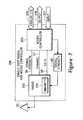
- FIG. 7is a block diagram of an embodiment of a single chip radio and micro controller.
- FIG. 8is a flow diagram of one embodiment of a method associated with the system and single chip radio and micro controller shown in FIGS. 6 and 7 , respectively.
- Described hereinis a method and apparatus for establishing a wireless link between devices.
- the following descriptionsets forth numerous specific details such as examples of specific systems, components, methods, and so forth, in order to provide a good understanding of several embodiments of the present invention. It will be apparent to one skilled in the art, however, that at least some embodiments of the present invention may be practiced without these specific details. In other instances, well-known components or methods are not described in detail or are presented in simple block diagram format in order to avoid unnecessarily obscuring the present disclosure. Thus, the specific details set forth are merely exemplary. Particular implementations may vary from these exemplary details and still be contemplated to be within the spirit and scope of the present invention.
- Embodiments of the present inventionprovide a system that includes a wireless link that can be used for devices such as sensors, cameras and actuators.
- the wireless linkhas high noise immunity, operates at high speed, can carry real time data such as camera images, and can connect sensors or actuators to the Internet.
- Embodiments of the present inventionprovide a wireless interface to industrial devices such an industrial device network may be rapidly installed in an existing building.
- FIG. 1is an overall block diagram of one embodiment of a system that connects a plurality of sensors 107 and actuators 108 to a host computer 101 .
- Host computer 101may be a stand alone computer such as, for example, a personal computer. Furthermore, it may be connected to the Internet through a connection that is not specifically shown in the drawing.
- sensors 107 A, 107 B and 107 Care merely representative and in most specific applications there may be a plurality of such sensors.
- actuators 108 A and 108 Bare shown in FIG. 1 ; however, the system may include many such actuators.
- Actuatorsmay perform a wide variety of functions, for example, the actuators may be devices that turn on a siren or turn on a warning light.
- the overall function of the systemis to connect sensors 107 and actuators 108 to host 101 .
- the systemincludes a power line interface network 102 , an industrial device node 104 , a radio transmitter-receiver 105 , and a single chip radio and a micro controller 106 .
- the power line network 102includes network interfaces 102 A and 102 C that communicate through a power line network 102 B.
- the radio link from the single chip radio and micro controller 106 to radio device 105merely transmits the data from the sensors 107 and actuators 108 to the radio 105 , which is then transmitted to the industrial device node 104 . Commands can also be transmitted back to the actuators 108 or to sensors 107 via this radio link.
- FIG. 2is a block diagram of the single chip radio and micro controller 106 .
- the single chip radio and micro controller 106includes a radio transmitter-receiver 202 and a programmable micro controller 203 , which reside on a common carrier substrate.
- the common carrier substratemay be, for example, an integrated circuit (IC) die substrate, a multi-chip module substrate, or the like.
- ICintegrated circuit
- the term “single chip”may hereinafter be used to indicate that these components reside on a common carrier substrate.
- the single chip radio and micro controller 106provides bi-directional communication with sensors 107 and actuators 108 . That is, the single chip radio and micro controller 106 both (1) receives data from sensors 107 and transmits the data to radio 105 and (2) receives commands from radio 105 and transmits these commands to the sensors 107 or to actuators 108 .
- the sensor 107is a camera
- imageswould be sent from the camera to single chip radio and micro controller 106 and commands could be sent from the single chip radio and micro controller to the camera to instruct the camera to change its direction of view.
- Microcontroller 203can, for example, be the microcontroller developed by Cypress Semiconductor Corporation of San Jose, Calif. under the trademarks Programmable System-on-ChipTM and PSoCTM.
- the Programmable System-on-Chip microprocessoris a true System-on-Chip.
- the PSoCTMis a high-performance, field-programmable, mixed-signal array suitable for embedded-control functions in consumer, industrial, office automation, telecom and automotive applications.
- the PSoCTM deviceprovides highly stable, instrumentation quality analog performance, including rail-to-rail inputs; programmable gain; and 14-bit analog-to-digital converters (up to four independent converters are available in a single PSoCTM device).
- the Cypress Semiconductor Corporation PSoCTMhas low noise, low input leakage and low voltage offset, and it has an 8-bit micro controller core. In various other embodiments various other types of micro controllers can be used.
- the micro controller 203has analog input-output 205 , data output channel 206 and data input channel 207 .
- the input output channels 205 , 206 and 207can be connected to sensors such as sensors 107 and actuators 108 .
- the radio 202can be a normal state of the art radio transmitter receiver. Radio 202 has an associated antenna 201 .
- the industrial device node 104 shown in FIG. 1can be a commercially available industrial device node.
- industrial device node 104may include the type of microcontroller developed by Cypress Semiconductor Corporation of San Jose, Calif. under the trademark Neuron®.
- the Neuro® chips marketed by Cypressmay be commercially available under the designations CY7C53120L8 and CY7C53150L.
- the Neuron® micro controlleris a 3.3 volt microcontroller that has been optimized for control networking applications.
- the low power specification, increased I/O performance and higher memory integrationmakes this micro controller suitable for use for collecting data from sensors and actuators and for reporting such data.
- the difference between the CY7C53120L8 and CY7C53150Lis that the CY7C53120L8 has 16 Kbyte of ROM, 4 Kbyte of RAM and 8 Kbyte of internal EEPROM. On the other hand, the CY7C53150L has 4 Kbyte of RAM and 2.7 Kbyte of EEPROM. Both devices feature three 8 bit pipelined processors that enable concurrent processing of application code and network traffic at speeds of up to 20 MHz. Both the CY7C53120L8 and CY7C53150L have a hardware-based serial communications interface (UART) and serial peripheral interface (SPI) engine that is scalable to 2.5 Mbit/s, and a programmable low voltage inhibitor (LVI). Both devices have in-system programming via an 11-pin configurable I/O block and a flexible five-pin communications port that can be configured to interface with a variety of 5 and 3.3V media transceivers over a wide range of data rates.
- UARThardware-based serial communications interface
- SPIserial peripheral interface
- LTI
- the particular industrial device node chosen for any particular specific applicationdepends upon the specific engineering specifications of the particular application. Different specific embodiments would use different industrial device nodes. In addition to the specific industrial device node described above, in other embodiments other industrial device nodes by other manufacturers can be used.
- the power line network 102can consist of commercially available components. Two of the companies that market such components are Intelogis Technologies Inc., located in Draper, Utah, and Intellon Inc. located in Ocala, Fla. Intellon markets a power line network technology under the trademark PowerPacket.
- the Intellon power line networkuses an enhanced form of orthogonal frequency-division multiplexing (OFDM).
- OFDMorthogonal frequency-division multiplexing
- the power line networking system marketed by Intellonutilizes forward error-correction to minimize errors. It is noted that OFDM is a variation of the frequency-division multiplexing (FDM) used in phone line networking and in technology found in DSL modems.
- OFDMdivides the available range of frequencies which includes frequencies in the range 4.3 MHz to 20.9 MHz, into 84 separate carriers. OFDM sends packets of data simultaneously along several of the carrier frequencies, allowing for increased speed and reliability. If noise or a surge in power usage disrupts one of the frequencies, the PowerPacket chip may sense such a disruption and switch that data to another carrier. This rate-adaptive design allows PowerPacket to maintain an Ethernet-class connection throughout the power-line network without losing any data.
- FIG. 3is a block flow diagram illustrating the operation of the system. That is, FIG. 3 indicates how data is transmitted from sensors 107 to computer 101 . As indicated by block 301 , data from the sensors 107 is sent to the microcontroller 203 . This data can either be transmitted on analog I/O 205 if the sensors 107 provide analog data or the data from the sensors 107 can be provided to microcontroller 203 as digital data on input 207 . Which input channel is connected to the sensor depends on the particular characteristics of the particular sensor 107 .
- an analog to digital converterthat is part of micro controller 203 (but which is not explicitly shown in the drawing) converts the analog signal to a digital signal. This is indicated by block 302 .
- the digital signal which indicates a value from sensors 107is transferred to radio 202 and transmitted over the air. Since radio 202 and micro controller 203 are on a single chip, the transmission from micro controller 203 to radio 202 can be done on a bus that is internal to the chip. In this embodiment, they are connected by a Serial Peripheral Interface (SPI) bus. It is noted that the PSoCTM from Cypress Semiconductor Corporation, which was described above, includes an SPI bus. SPI is a standard parallel Small Computer System Interface (SCSI) type of bus. Thus, data can be transferred at a high rate of speed.
- SPISerial Peripheral Interface
- the signalsare received by radio transmitter/receiver 105 . From radio transmitter/receiver 105 , the signals are transmitted to industrial device node 104 .
- the industrial device node 104sends the signals over the over line network 102 . That is, the industrial device node 104 sends the signals to power line interface device 103 C, which in turn transmits the signals over the power line network. The signals are in turn detected by power line network interface device 102 A.
- the host computer 101may be a personal computer or it may be some other type of network computer.
- the computer 101may in turn be connected to the Internet.
- FIG. 4illustrates how data is sent from computer 101 to actuators 108 .
- the computer 101transmits a command to power line network 102 .
- the commandis transmitted through the power line network 102 , that is, the command goes from interface device 102 A, through the network 102 B, and then to power line network interface 103 C. After passing through the power line network 102 , the command may arrive at industrial device node 104 .
- the industrial device node 104sends the command to radio transmitter 105 , which transmits the command over the air as indicated by block 403 .
- the commandis received by antenna 201 and sent to radio receiver 202 as indicated by block 404 .
- the commandis sent to micro controller 203 as indicated by block 406 .
- the micro controller 203in turn sends the command to actuator 108 as indicated by block 408 .
- micro controller 203 and industrial device node 104are programmable device. These programmable devices can include programs that detect a particular sequence of signals from sensors 107 and possible from external sources such as from a timer or manual switch.
- these programmable unitsmay initiate action. They, rather than host computer 101 , may initiate signals that are sent to actuators 108 . These programmable units can also send control signals to sensors 107 , as for example, to change the orientation of a camera.
- FIG. 5One embodiment of a system that connects a plurality of sensors 107 and actuators 108 to a host computer 101 is shown in FIG. 5 .
- the difference between the first embodiment described above with respect to FIG. 1 and this alternate embodimentis the fact that in this alternate embodiment there is a direct hard wired connection 501 from the single chip radio and micro controller 106 to the a second industrial device node 502 .
- the industrial device node 502is in turn connected to a power line network interface 503 C.
- the power line network interface 503 Cis connected to the power line network 102 in the same manner that power line interface 103 C is connected to power line network 102 .
- both industrial device node 104 and industrial device node 502are connected to the power line network 102 , and from there to computer 101 .
- the programming in single chip receiver 106 in this second embodimenthas an added subroutine which detects that the wireless link between radio device 105 and radio 202 is not operating. In this situation signals are sent and received from host computer 101 via the hard wired backup link 501 rather than via the radio link. This backup hard wired link provides added security that the system can remain operational even if some of the links in the system fail to operate for some reason.
- the sensors and the actuatorsare shown as separate units; however, in many systems sensors and actuators are combined in one physical unit.
- the term sensor/actuatoris used to mean either a sensor or an actuator or a unit that combines both sensor and actuator functions.
- a heat or fire detectormay be combined with an alarm bell, such that when the sensor detects a fire, the alarm bell is sounded and at the same time a signal is sent to the single chip radio micro controller that is connected to the sensor.
- sensor/actuator unitsare commercially available. Many of the commercially available sensors and actuator units provide analog or digital signal outputs and/or can accept analog or digital command signals.
- sensor/actuatoras used herein is intended to mean any type of sensor, any type of actuator, or any type of combined sensor and actuator. Any sensor or actuator that provides an analog or digital output signal, and/or a port to receive digital or analog signals, can be used in specific embodiments of the present invention. As a matter of engineering detail, voltage levels may be taken into account and adjusted appropriately.
- FIG. 6is a block diagram of an embodiment of a system that connects a plurality of sensors 107 and actuators 108 to a host computer 101 using the single chip radio and microcontroller 106 and the radio 105 .
- FIG. 7is a block diagram of the single chip radio and micro controller 106 shown in FIGS. 1 and 6 .
- Like numbers in the figures, particularly FIGS. 1 and 6refer to like elements, and their attendant descriptions we provide above.
- the single chip radio and micro controller 106transmits the data from the sensors 107 and actuators 108 to the radio 105 , which then transmits the data to the industrial device node 104 . Commands can also be transmitted back to the actuators 108 or to sensors 107 via the radio link between the radio 105 and the single chip radio and micro controller 106 .
- the normal wireless operating rangecan refer to a range of distances between the host computer 101 and the single chip radio and micro controller 106 when conducting wireless communications.
- the normal wireless operating rangecan also refer to the wireless signal amplification levels or power levels normally used in the single chip radio and micro controller 106 when conducting normal data and message communications.
- the single chip radio and micro controller 106When the single chip radio and micro controller 106 seeks to be connected to the host computer 101 it can reduce its normal operating range to a reduced binding range. This can occur when the radio and micro controller 106 (or host computer 101 ) powers up, when the radio and micro controller 106 does not know the identification number of the host computer 101 , or when the radio and micro controller 106 (or host computer 101 ) loses or drops any previously established wireless connection for any reason. Or the single chip radio and micro controller 106 can reduce its operating range from the normal operating range to the reduced binding range when a user presses a button (not shown) located on, e.g., the radio chip and micro controller 106 .
- the reduced binding rangecan refer to a reduced narrower range of distances between the radio and micro controller 106 and the host computer 101 or, more particularly to radio 105 .
- the host computer 101we refer to the host computer 101 as the system including the radio 105 .
- the radio and micro controller 106can be physically located next to the host computer 101 to conduct wireless communications particularly those relating to binding.
- the single chip radio and micro controller 106switches to the reduced binding range by reducing the amplification level of signals transmitted to the host computer 101 .
- the single chip radio and micro controller 106can send a bind channel change request 22 on all channels 24 requesting any host to enter into a pairing or binding mode. All channels 24 can include any channels that the host computer 101 may currently be operating on. Because the radio and micro controller 106 is transmitting at a low power level, the bind channel change request 22 can only be processed by a host computer 101 that is in relatively close proximity to the radio and micro controller 106 . The binding handshake exchange, therefore, can be initiated by a user moving the radio and micro controller 106 close to the host computer 101 .
- the reduced binding rangemay be around 6-12 inches or 15-30 centimeters.
- the reduced binding rangereduces the possibility that the single chip radio and micro controller 106 unintentionally binds to the wrong host.
- the host computer 101can reduce the transmit power level and/or receive sensitivity responsive to the bind channel change request 22 .
- the host computer 101 and the single chip radio and micro controller 106enter a pairing or binding mode where each is configured to operate on a particular bind channel.
- the bind channelis used for binding operations only. For example, in current spread spectrum wireless systems, this could be channel 78 (not shown) while channels 0-77 (not shown) are used for normal communications. Any predefined channel may suffice.
- the bind channel change request 22can identify the bind channel that the host computer 101 and the single chip radio and micro controller 106 can use for conducting binding operations. The bind channel change request 22 notifies the host computer 101 to change to the bind mode.
- binding operationsthe single chip radio and micro controller 106 and the host computer 101 exchange binding messages 24 , 26 , and 28 successfully if they are in relatively close proximity.
- the bind request 24causes the host computer to send back a bind response 26 that identifies a wireless channel for conducting normal wireless communications.
- the response 26can also include an identifier that is used by the single chip radio and micro controller 106 to identify wireless communications from the host computer 101 .
- the single chip radio and micro controller 106sends a control response 28 back to the host computer 101 that acknowledges the previous bind response 26 and causes both the single chip radio and micro controller 106 and the host computer 101 to revert back to a normal operating mode.
- the radio and micro controller 106may visually and/or audibly notify the user that the binding operations were successfully completed.
- the visual and/or audible notificationcan take on any form known to a person of reasonable skill in the art, including lighting light emitting diode (LED) located on the host computer 101 or controlled by the radio 106 .
- LEDlighting light emitting diode
- the host computer 101 and the single chip radio and micro controller 106switch to the normal wireless operating range to communicate with each other.
- the single chip radio and micro controller 106 and the host computer 101may increase the signal strengths of their transmit and receive signals when operating in the normal wireless operating mode.
- the reduced binding rangemay be around 6-12 inches or 15-30 centimeters.
- the reduced binding rangereduces the possibility that the single chip radio and micro controller 106 unintentionally binds to the wrong host computer.
- the normal operating rangeis around 10-20 meters. These are only exemplary ranges.
- the reduced binding and the normal operating rangescan have any range known to a person of skill in the art.
- the radio 106 and/or host 101can vary the signal strengths of transmit or receive signals and the corresponding amount of signal strength reduction according to the desired operating parameters of the wireless system.
- the single chip radio and micro controller 106includes a micro controller 203 that controls the operation of a radio 202 as we explain in more detail above.
- the radio 202can be any conventional transceiver that transmits and receives wireless signals over any available channel.
- the single chip radio and micro controller 106can include the micro controller 203 .
- the micro controller 203can be a reprogrammable flash type micro controller, or any other type of controller known to a person of skill in the art.
- a reprogrammable flash type micro controller 203allows continuous firmware changes and eliminates the need for an external memory, e.g., electrically erasable programmable read only memory (EEPROM), to store binding parameters.
- a high speed bi-directional connectioncouples the radio 202 and the controller 203 and is integrated into the single chip. In an embodiment, the high speed bi-directional connection is a SCSI bus.
- the micro controller 203sends data 58 to the radio 202 that is then encoded into wireless signals that the antenna 55 transmits over one of the available wireless channels. Similarly, the radio 202 decodes any signals it receives over the wireless channel into digital data that it sends to the micro controller 203 for additional processing.
- the micro controller 203outputs a signal strength control signal 56 that is used by the radio 202 to adjust the amplification of the transmitted and/or received wireless signals. For example, a lower value is sent on signal strength signal 56 when the micro controller 203 wants the radio 202 to operate in the reduced binding range.
- the radio 202then varies the amplification of transmit or receive signals according to the signal 56 .
- a signal strength controller or monitor 60can direct the radio 202 to increase or decrease the signal strength of any of the signals transmitted during the binding mode operation. If the host 101 determines that the signal strength of the bind channel change request signal 22 ( FIG. 6 ) or the bind request packet 24 is below a predetermined threshold, the host 101 may ignore the received packet, thereby preventing binding to a wrong device.
- the normal transmit or received signal strengths and the corresponding amount of signal strength reductioncan be varied according to the desired operating parameters of the wireless system.
- the radio 202transmits wireless signals using a Bluetooth, IEEE 802.11, or some other spread spectrum transmission protocol. It is notable that the reduced binding range can be used with or by any wireless system that performs binding operations.
- the micro controller 203operates the radio 202 in both the normal communications range and the reduced binding range.
- the micro controller 203can automatically operate the radio 202 in the reduced binding range when pairing with a host computer 101 and can operate the radio 202 in the normal communications range after it is successfully paired with the host computer 101 .
- the micro controller 203can change between the different channels by varying the channel signal value 57 and controls the sending of the bind channel change request signal 22 on each of the plurality of different wireless channels.
- the micro controller 203can also switch the radio 202 to start operating on the bind channel by setting an associated channel value 57 .
- the micro controller 203can activate a visual indication of successful bind operations by e.g., lighting an associated LED.
- the reduced binding rangedoes not require any additional circuitry in the radio 202 .
- alternative ways to reduce the effective communication range between the single chip radio and micro controller 202 and the host computer 101include bypassing the antenna 55 .
- Other hardwarecould also be used to trigger the radio 106 and the host 101 to enter the pairing mode.
- the single chip radio and microcontroller 106switches to using the reduced binding range when detecting that the host computer 101 is within a threshold proximity.
- a proximity switchsuch as a magnetic reed switch could be used as a trigger to indicate when the single chip radio and micro controller 106 is held close enough to the host computer 101 (and its associated radio 105 ) for effectively starting and successfully concluding binding.
- the host computer 101can include a large magnet that activates the magnetic reed switch when the two devices are within binding range.
- the radio 202can be a transceiver operating at various frequency bands, e.g., the 2.4 GHz ISM (industrial, scientific, and medical) bands.
- the radio 202can include interference immunity circuitry 210 to prevent noise from substantially interfering with the wireless communication between the single chip radio and micro controller 106 and radio device 105 .
- the interference immunity circuitry 210can allow the single chip radio and micro controller 106 to operate well in crowded RF environments.
- the interference immunity circuitry 210can include the binding technology described above and in U.S. patent application Ser. No. 11/027,005, filed Dec. 30, 2004, and titled Method and Apparatus for Binding Wireless Devices.
- the interference immunity circuitry 210can alternatively use any wireless immunity circuitry known to a person of reasonable skill in the art.
- the integration of the radio 202 and the micro controller 203 on a single chipenables a component reduction that adds up to significant savings for wireless PC peripherals.
- the integrationalso reduces power consumption extending battery life.
- FIG. 8is a flow diagram of a method 800 associated with the system and single chip radio and micro controller shown in FIGS. 6 and 7 , respectively.
- the single chip radio and micro controller 106enters into a bind mode at 802 .
- the single chip radio and micro controller 106may not have an identification number for the host 101 or operating channel configured for sending wireless communications. Or the wireless connection may be dropped or lost.
- the single chip radio and micro controller 203transmits a bind channel change request 22 on a plurality of channels.
- the bind channel change request 22may include a bind channel over which the radio 106 can wireless communicate with the host 101 .
- the host 101acknowledges receipt of the bind channel change request 22 by changing to the bind channel.
- the radio 106also changes to the bind channel at 808 . By doing so, the host 101 and the radio 106 establish a wireless link that allows for the transmission and receipt of messages over the bind channel.
- the single chip radio and micro controller 106transmits a bind request 24 soliciting a bind response 26 from the host 101 .
- the host 101may check the signal strength of the received bind request signal 24 to determine whether to respond. If, for example, the bind request signal 24 is below a predefined threshold, the host 101 may not respond to prevent two host devices, in close proximity, from binding to the same radio 106 . If a received signal strength indication (RSSI) level is above the predefined threshold, the host 101 transmits a response 26 to the single chip radio and micro controller 106 at 812 .
- the response 26identifies to the radio 106 , the channel that is going to be used for normal communications and well as providing a host 101 identification number or value.
- RSSIreceived signal strength indication
- the radio 106transmits a control response 28 at 814 .
- the control response 28acknowledges receipt of the response 26 as well as provides any other control information to the host 101 .
- the host 101 and the single chip radio and micro controller 106exit the bind mode and begin operating at the normal wireless communication range using the normal communication channel.
- Certain embodimentsmay be implemented as a computer program product that may include instructions stored on a computer-readable medium. These instructions may be used to program a general-purpose or special-purpose processor to perform the described operations.
- a computer-readable mediumincludes any mechanism for storing or transmitting information in a form (e.g., software, processing application) readable by a computer.
- the computer-readable mediummay include, but is not limited to, magnetic storage medium (e.g., floppy diskette); optical storage medium (e.g., CD-ROM); magneto-optical storage medium; read-only memory (ROM); random-access memory (RAM); erasable programmable memory (e.g., EPROM and EEPROM); flash memory; or another type of medium suitable for storing electronic instructions.
- some embodimentsmay be practiced in distributed computing environments where the computer-readable medium is stored on and/or executed by more than one computer system.
- the information transferred between computer systemsmay either be pulled or pushed across the communication medium connecting the computer systems.
Landscapes
- Engineering & Computer Science (AREA)
- Computer Networks & Wireless Communication (AREA)
- Signal Processing (AREA)
- Physics & Mathematics (AREA)
- Electromagnetism (AREA)
- Quality & Reliability (AREA)
- Selective Calling Equipment (AREA)
Abstract
Description
Claims (20)
Priority Applications (1)
| Application Number | Priority Date | Filing Date | Title |
|---|---|---|---|
| US12/239,602US8140013B1 (en) | 2003-06-04 | 2008-09-26 | Wireless communication device and method |
Applications Claiming Priority (5)
| Application Number | Priority Date | Filing Date | Title |
|---|---|---|---|
| US47653003P | 2003-06-04 | 2003-06-04 | |
| US85967504A | 2004-06-02 | 2004-06-02 | |
| US11/027,005US7848703B1 (en) | 2004-12-30 | 2004-12-30 | Method and apparatus for binding wireless devices |
| US97639807P | 2007-09-28 | 2007-09-28 | |
| US12/239,602US8140013B1 (en) | 2003-06-04 | 2008-09-26 | Wireless communication device and method |
Related Parent Applications (1)
| Application Number | Title | Priority Date | Filing Date |
|---|---|---|---|
| US11/027,005Continuation-In-PartUS7848703B1 (en) | 2003-06-04 | 2004-12-30 | Method and apparatus for binding wireless devices |
Publications (1)
| Publication Number | Publication Date |
|---|---|
| US8140013B1true US8140013B1 (en) | 2012-03-20 |
Family
ID=45813403
Family Applications (1)
| Application Number | Title | Priority Date | Filing Date |
|---|---|---|---|
| US12/239,602Expired - Fee RelatedUS8140013B1 (en) | 2003-06-04 | 2008-09-26 | Wireless communication device and method |
Country Status (1)
| Country | Link |
|---|---|
| US (1) | US8140013B1 (en) |
Cited By (4)
| Publication number | Priority date | Publication date | Assignee | Title |
|---|---|---|---|---|
| US20100177707A1 (en)* | 2009-01-13 | 2010-07-15 | Metrologic Instruments, Inc. | Method and apparatus for increasing the SNR at the RF antennas of wireless end-devices on a wireless communication network, while minimizing the RF power transmitted by the wireless coordinator and routers |
| US20120144473A1 (en)* | 2006-08-30 | 2012-06-07 | Apple Inc. | Pairing of wireless devices using a wired medium |
| US20120182905A1 (en)* | 2011-01-13 | 2012-07-19 | Sony Corporation | Communication system and communication device |
| RU2674882C1 (en)* | 2017-08-24 | 2018-12-13 | Общество с ограниченной ответственностью "СОВРЕМЕННЫЕ РАДИО ТЕХНОЛОГИИ" | Single unit radio modem |
Citations (45)
| Publication number | Priority date | Publication date | Assignee | Title |
|---|---|---|---|---|
| US5680102A (en) | 1994-07-29 | 1997-10-21 | Dimango Products | RF data communication link for wireless audible indication system |
| US5900806A (en) | 1992-05-22 | 1999-05-04 | Issa; Darrell E. | Alarm sensor multiplexing |
| US5955700A (en) | 1997-12-30 | 1999-09-21 | Motorola, Inc. | Housing unit including a latching mechanism with a cam |
| US6238338B1 (en) | 1999-07-19 | 2001-05-29 | Altec, Inc. | Biosignal monitoring system and method |
| US20010049740A1 (en) | 2000-03-22 | 2001-12-06 | Karpoff Wayne T. | Method and system for providing multimedia information on demand over wide area networks |
| US20030006737A1 (en) | 1998-03-10 | 2003-01-09 | Lafollette Rodney M. | Micro power supply with integrated charging capability |
| US20030063003A1 (en) | 2001-09-28 | 2003-04-03 | Bero Robert J. | Proximity monitoring communication system |
| US20030073461A1 (en) | 1999-10-12 | 2003-04-17 | John Sinclair | Wireless comumnication and control system |
| US20030138941A1 (en) | 2001-10-26 | 2003-07-24 | Haiqing Gong | Sample preparation integrated chip |
| US20030151600A1 (en) | 2002-02-14 | 2003-08-14 | Tsuneo Takeuchi | Display device, electronic appliance and camera |
| US6615301B1 (en) | 1998-03-09 | 2003-09-02 | Samsung Electronics, Co., Ltd | Integrated data transceiver circuit for use with a serial bus and bus interface |
| US20030178395A1 (en) | 2000-05-24 | 2003-09-25 | Duignan Michael T. | Method and apparatus for fabrication of miniature structures |
| US20030190906A1 (en) | 2002-04-09 | 2003-10-09 | Honeywell International, Inc. | Security control and communication system and method |
| US6690056B1 (en) | 1999-04-06 | 2004-02-10 | Peregrine Semiconductor Corporation | EEPROM cell on SOI |
| US6708288B1 (en) | 2000-10-31 | 2004-03-16 | Hewlett-Packard Development Company, L.P. | Compiler-based checkpointing for support of error recovery |
| US6741178B1 (en) | 1992-06-17 | 2004-05-25 | Micron Technology, Inc | Electrically powered postage stamp or mailing or shipping label operative with radio frequency (RF) communication |
| US20040107435A1 (en) | 2002-08-21 | 2004-06-03 | Nippon Telegraph And Telephone Corporation | Information providing apparatus and information providing method |
| US20040130446A1 (en) | 2003-01-06 | 2004-07-08 | Chen Thomas C. H. | Wireless communication and global location enabled intelligent health monitoring system |
| US20040139110A1 (en) | 2002-12-31 | 2004-07-15 | Lamarca Anthony G. | Sensor network control and calibration system |
| US20040176032A1 (en) | 2002-03-26 | 2004-09-09 | Sakari Kotola | Radio frequency identification (RF-ID) based discovery for short range radio communication with reader device having transponder functionality |
| US6823186B2 (en) | 2000-12-28 | 2004-11-23 | Nokia Corporation | Apparatus, and associated method, for allocating channel capacity in a wireless communication system |
| US20050048919A1 (en) | 2003-08-28 | 2005-03-03 | Alcatel | Distributed pairing between different terminals |
| US20050064814A1 (en) | 2003-07-22 | 2005-03-24 | Sony Corporation | Communication apparatus |
| US6956480B2 (en) | 2000-06-16 | 2005-10-18 | Nokia Mobile Phones Limited | Electronic apparatus including a device for preventing loss or theft |
| US6961541B2 (en) | 2002-05-24 | 2005-11-01 | Aeroscout, Inc. | Method and apparatus for enhancing security in a wireless network using distance measurement techniques |
| US6970183B1 (en) | 2000-06-14 | 2005-11-29 | E-Watch, Inc. | Multimedia surveillance and monitoring system including network configuration |
| US20050266798A1 (en) | 2004-05-31 | 2005-12-01 | Seamus Moloney | Linking security association to entries in a contact directory of a wireless device |
| US20050282588A1 (en) | 2004-06-22 | 2005-12-22 | Nokia Corporation | Intuitive energy management of a short-range communication transceiver associated with a mobile terminal |
| US20050287950A1 (en)* | 2004-06-23 | 2005-12-29 | Jan-Willem Helden | Method and apparatus for pairing and configuring wireless devices |
| US20060035590A1 (en) | 2004-03-16 | 2006-02-16 | Morris Martin G | High-reliability computer interface for wireless input devices |
| US20060053276A1 (en) | 2004-09-03 | 2006-03-09 | Lortz Victor B | Device introduction and access control framework |
| US7026983B2 (en) | 2000-07-18 | 2006-04-11 | Hewlett-Packard Development Company, L.P. | Location data diffusion and location discovery |
| US20060105712A1 (en) | 2004-11-12 | 2006-05-18 | Microsoft Corporation | Wireless device support for electronic devices |
| US7072615B1 (en) | 1999-08-25 | 2006-07-04 | Cedardell Limited | Automatic installation process for wireless communication system |
| US20060149963A1 (en) | 2003-11-13 | 2006-07-06 | Lu Hongqian K | System and method for data communications allowing slave device to be network peers |
| US20060183462A1 (en) | 2005-02-11 | 2006-08-17 | Nokia Corporation | Managing an access account using personal area networks and credentials on a mobile device |
| US20060199536A1 (en) | 2005-03-07 | 2006-09-07 | Broadcom Corporation | Automatic network and device configuration for handheld devices based on bluetooth device proximity |
| US20060234630A1 (en) | 2004-12-23 | 2006-10-19 | Frederick Lai | Ping feature for electronic devices |
| US7142814B2 (en) | 2002-12-11 | 2006-11-28 | Shary Nassimi | Automatic Bluetooth inquiry mode headset |
| US7173990B2 (en)* | 2001-12-27 | 2007-02-06 | Dsp Group Inc. | Joint equalization, soft-demapping and phase error correction in wireless system with receive diversity |
| US7174130B2 (en) | 2001-09-12 | 2007-02-06 | Agere Systems Inc. | Security apparatus and method during BLUETOOTH pairing |
| US7209705B2 (en) | 2001-11-14 | 2007-04-24 | Samsung Electronics Co., Ltd. | Method and apparatus for optional automatic configuration of wireless communications device behavior within small area transmitter service regions |
| US20070093207A1 (en) | 2005-10-25 | 2007-04-26 | Samsung Electronics Co., Ltd. | Method and apparatus for automatic bluetooth connection in a mobile communication terminal |
| US7379447B2 (en) | 2003-05-02 | 2008-05-27 | Microsoft Corporation | Slotted seeded channel hopping for capacity improvement in wireless networks |
| US7848703B1 (en)* | 2004-12-30 | 2010-12-07 | Cypress Semiconductor Corporation | Method and apparatus for binding wireless devices |
- 2008
- 2008-09-26USUS12/239,602patent/US8140013B1/ennot_activeExpired - Fee Related
Patent Citations (46)
| Publication number | Priority date | Publication date | Assignee | Title |
|---|---|---|---|---|
| US5900806A (en) | 1992-05-22 | 1999-05-04 | Issa; Darrell E. | Alarm sensor multiplexing |
| US6741178B1 (en) | 1992-06-17 | 2004-05-25 | Micron Technology, Inc | Electrically powered postage stamp or mailing or shipping label operative with radio frequency (RF) communication |
| US5680102A (en) | 1994-07-29 | 1997-10-21 | Dimango Products | RF data communication link for wireless audible indication system |
| US5955700A (en) | 1997-12-30 | 1999-09-21 | Motorola, Inc. | Housing unit including a latching mechanism with a cam |
| US6615301B1 (en) | 1998-03-09 | 2003-09-02 | Samsung Electronics, Co., Ltd | Integrated data transceiver circuit for use with a serial bus and bus interface |
| US6765363B2 (en) | 1998-03-10 | 2004-07-20 | U.S. Microbattery, Inc. | Micro power supply with integrated charging capability |
| US20030006737A1 (en) | 1998-03-10 | 2003-01-09 | Lafollette Rodney M. | Micro power supply with integrated charging capability |
| US6690056B1 (en) | 1999-04-06 | 2004-02-10 | Peregrine Semiconductor Corporation | EEPROM cell on SOI |
| US6238338B1 (en) | 1999-07-19 | 2001-05-29 | Altec, Inc. | Biosignal monitoring system and method |
| US7072615B1 (en) | 1999-08-25 | 2006-07-04 | Cedardell Limited | Automatic installation process for wireless communication system |
| US20030073461A1 (en) | 1999-10-12 | 2003-04-17 | John Sinclair | Wireless comumnication and control system |
| US20010049740A1 (en) | 2000-03-22 | 2001-12-06 | Karpoff Wayne T. | Method and system for providing multimedia information on demand over wide area networks |
| US20030178395A1 (en) | 2000-05-24 | 2003-09-25 | Duignan Michael T. | Method and apparatus for fabrication of miniature structures |
| US6970183B1 (en) | 2000-06-14 | 2005-11-29 | E-Watch, Inc. | Multimedia surveillance and monitoring system including network configuration |
| US6956480B2 (en) | 2000-06-16 | 2005-10-18 | Nokia Mobile Phones Limited | Electronic apparatus including a device for preventing loss or theft |
| US7026983B2 (en) | 2000-07-18 | 2006-04-11 | Hewlett-Packard Development Company, L.P. | Location data diffusion and location discovery |
| US6708288B1 (en) | 2000-10-31 | 2004-03-16 | Hewlett-Packard Development Company, L.P. | Compiler-based checkpointing for support of error recovery |
| US6823186B2 (en) | 2000-12-28 | 2004-11-23 | Nokia Corporation | Apparatus, and associated method, for allocating channel capacity in a wireless communication system |
| US7174130B2 (en) | 2001-09-12 | 2007-02-06 | Agere Systems Inc. | Security apparatus and method during BLUETOOTH pairing |
| US20030063003A1 (en) | 2001-09-28 | 2003-04-03 | Bero Robert J. | Proximity monitoring communication system |
| US20030138941A1 (en) | 2001-10-26 | 2003-07-24 | Haiqing Gong | Sample preparation integrated chip |
| US7209705B2 (en) | 2001-11-14 | 2007-04-24 | Samsung Electronics Co., Ltd. | Method and apparatus for optional automatic configuration of wireless communications device behavior within small area transmitter service regions |
| US7173990B2 (en)* | 2001-12-27 | 2007-02-06 | Dsp Group Inc. | Joint equalization, soft-demapping and phase error correction in wireless system with receive diversity |
| US20030151600A1 (en) | 2002-02-14 | 2003-08-14 | Tsuneo Takeuchi | Display device, electronic appliance and camera |
| US20040176032A1 (en) | 2002-03-26 | 2004-09-09 | Sakari Kotola | Radio frequency identification (RF-ID) based discovery for short range radio communication with reader device having transponder functionality |
| US20030190906A1 (en) | 2002-04-09 | 2003-10-09 | Honeywell International, Inc. | Security control and communication system and method |
| US6961541B2 (en) | 2002-05-24 | 2005-11-01 | Aeroscout, Inc. | Method and apparatus for enhancing security in a wireless network using distance measurement techniques |
| US20040107435A1 (en) | 2002-08-21 | 2004-06-03 | Nippon Telegraph And Telephone Corporation | Information providing apparatus and information providing method |
| US7142814B2 (en) | 2002-12-11 | 2006-11-28 | Shary Nassimi | Automatic Bluetooth inquiry mode headset |
| US20040139110A1 (en) | 2002-12-31 | 2004-07-15 | Lamarca Anthony G. | Sensor network control and calibration system |
| US20040130446A1 (en) | 2003-01-06 | 2004-07-08 | Chen Thomas C. H. | Wireless communication and global location enabled intelligent health monitoring system |
| US7379447B2 (en) | 2003-05-02 | 2008-05-27 | Microsoft Corporation | Slotted seeded channel hopping for capacity improvement in wireless networks |
| US20050064814A1 (en) | 2003-07-22 | 2005-03-24 | Sony Corporation | Communication apparatus |
| US20050048919A1 (en) | 2003-08-28 | 2005-03-03 | Alcatel | Distributed pairing between different terminals |
| US20060149963A1 (en) | 2003-11-13 | 2006-07-06 | Lu Hongqian K | System and method for data communications allowing slave device to be network peers |
| US20060035590A1 (en) | 2004-03-16 | 2006-02-16 | Morris Martin G | High-reliability computer interface for wireless input devices |
| US20050266798A1 (en) | 2004-05-31 | 2005-12-01 | Seamus Moloney | Linking security association to entries in a contact directory of a wireless device |
| US20050282588A1 (en) | 2004-06-22 | 2005-12-22 | Nokia Corporation | Intuitive energy management of a short-range communication transceiver associated with a mobile terminal |
| US20050287950A1 (en)* | 2004-06-23 | 2005-12-29 | Jan-Willem Helden | Method and apparatus for pairing and configuring wireless devices |
| US20060053276A1 (en) | 2004-09-03 | 2006-03-09 | Lortz Victor B | Device introduction and access control framework |
| US20060105712A1 (en) | 2004-11-12 | 2006-05-18 | Microsoft Corporation | Wireless device support for electronic devices |
| US20060234630A1 (en) | 2004-12-23 | 2006-10-19 | Frederick Lai | Ping feature for electronic devices |
| US7848703B1 (en)* | 2004-12-30 | 2010-12-07 | Cypress Semiconductor Corporation | Method and apparatus for binding wireless devices |
| US20060183462A1 (en) | 2005-02-11 | 2006-08-17 | Nokia Corporation | Managing an access account using personal area networks and credentials on a mobile device |
| US20060199536A1 (en) | 2005-03-07 | 2006-09-07 | Broadcom Corporation | Automatic network and device configuration for handheld devices based on bluetooth device proximity |
| US20070093207A1 (en) | 2005-10-25 | 2007-04-26 | Samsung Electronics Co., Ltd. | Method and apparatus for automatic bluetooth connection in a mobile communication terminal |
Non-Patent Citations (19)
| Title |
|---|
| U.S. Appl. No. 12/962,608: "Method and Apparatus for Binding Wireless Devices," Beard et al., filed on Dec. 7, 2010; 24 pages. |
| U.S. Appl. No. 13/287,521: "Method and Apparatus for Binding Wireless Devices," Beard, et al., filed on Nov. 2, 2011; 29 pages. |
| USPTO Advisory Action for U.S. Appl. No. 10/859,675 dated Jan. 12, 2007; 3 pages. |
| USPTO Final Rejection for U.S. Appl. No. 10/859,675 dated May 26, 2009; 7 pages. |
| USPTO Final Rejection for U.S. Appl. No. 10/859,675 dated Nov. 2, 2006; 8 pages. |
| USPTO Final Rejection for U.S. Appl. No. 11/027,005 dated Nov. 1, 2007; 20 pages. |
| USPTO Final Rejection for U.S. Appl. No. 11/027,005 dated Nov. 5, 2008; 14 pages. |
| USPTO Non-Final Rejection for U.S. Appl. No. 10/859,675 dated Jul. 12, 2006; 8 pages. |
| USPTO Non-Final Rejection for U.S. Appl. No. 10/859,675 dated Nov. 19, 2007; 7 pages. |
| USPTO Non-Final Rejection for U.S. Appl. No. 11/027,005 dated Feb. 16, 2010; 10 pages. |
| USPTO Non-Final Rejection for U.S. Appl. No. 11/027,005 dated May 14, 2007; 12 pages. |
| USPTO Non-Final Rejection for U.S. Appl. No. 11/027,005 dated May 15, 2008; 13 pages. |
| USPTO Non-Final Rejection for U.S. Appl. No. 12/962,608 dated Apr. 1, 2011; 23 pages. |
| USPTO Non-Final Rejection for U.S. Appl. No. 13/287,521 dated Dec. 7, 2011; 14 pages. |
| USPTO Notice of Allowance for U.S. Appl. No. 11/027,005 dated Jan. 28, 2009; 14 pages. |
| USPTO Notice of Allowance for U.S. Appl. No. 11/027,005 dated Jul. 27, 2010; 11 pages. |
| USPTO Notice of Allowance for U.S. Appl. No. 11/027,005 dated May 13, 2009; 13 pages. |
| USPTO Notice of Allowance for U.S. Appl. No. 11/027,005 dated Oct. 28, 2009; 13 pages. |
| USPTO Requirement for Restriction/Election for U.S. Appl. No. 10/859,675 dated Apr. 19, 2007; 3 pages. |
Cited By (4)
| Publication number | Priority date | Publication date | Assignee | Title |
|---|---|---|---|---|
| US20120144473A1 (en)* | 2006-08-30 | 2012-06-07 | Apple Inc. | Pairing of wireless devices using a wired medium |
| US20100177707A1 (en)* | 2009-01-13 | 2010-07-15 | Metrologic Instruments, Inc. | Method and apparatus for increasing the SNR at the RF antennas of wireless end-devices on a wireless communication network, while minimizing the RF power transmitted by the wireless coordinator and routers |
| US20120182905A1 (en)* | 2011-01-13 | 2012-07-19 | Sony Corporation | Communication system and communication device |
| RU2674882C1 (en)* | 2017-08-24 | 2018-12-13 | Общество с ограниченной ответственностью "СОВРЕМЕННЫЕ РАДИО ТЕХНОЛОГИИ" | Single unit radio modem |
Similar Documents
| Publication | Publication Date | Title |
|---|---|---|
| US8442437B1 (en) | Method and apparatus for binding wireless devices | |
| CA2311245C (en) | Multi tier wireless communication system | |
| CN102203833A (en) | Discovery protocol | |
| US20210126808A1 (en) | Multiprotocol audio/voice internet-of-things devices and related system | |
| US10945211B2 (en) | Underwater power saving mechanism for use in an communication network | |
| JP2009529294A5 (en) | ||
| US9001813B2 (en) | Radio system with configurable links | |
| US8140013B1 (en) | Wireless communication device and method | |
| US20090243847A1 (en) | Extension cord with environmental condition sensing ability | |
| CN107211201A (en) | Load control system, communicator, load control device and login method | |
| US8942186B2 (en) | Transmission and reception channel selection for communicating between a transmitter unit and a receiver unit | |
| US20180027638A1 (en) | Smart lighting system with ultra-low standby consumption | |
| US8547235B2 (en) | Security device and security system determining if the user can hear an audible alarm | |
| CN108427309A (en) | Intelligent home control system | |
| US20060255932A1 (en) | Method and Arrangement for Generating a Warning Signal in Two Devices Which are Adapted for Wireless Communication with One Another | |
| JPS631332A (en) | Home control device | |
| CN103426268A (en) | Method and system for preventing thievery for mobile equipment by aid of WIFI (wireless fidelity) module | |
| KR200415596Y1 (en) | Light on / off control system | |
| JP4661150B2 (en) | Lighting device communication setting method and lighting device | |
| CN112985508A (en) | Coding and communication method for multifunctional sensor output | |
| CN113225139A (en) | Underwater real-time bidirectional wireless communication method and device, electronic device and underwater equipment | |
| JP2004334445A (en) | Security glass and glass breakage detection device | |
| CN105139601A (en) | Wireless forwarding device for realizing connection between wired alarm detectors and wireless alarm host machine | |
| KR101568095B1 (en) | Low power can transeiver and operating method thereof | |
| JPH09149984A (en) | Game machine control system |
Legal Events
| Date | Code | Title | Description |
|---|---|---|---|
| AS | Assignment | Owner name:CYPRESS SEMICONDUCTOR CORPORATION, CALIFORNIA Free format text:ASSIGNMENT OF ASSIGNORS INTEREST;ASSIGNORS:BEARD, PAUL, MR.;WRIGHT, DAVID, MR.;SIGNING DATES FROM 20081120 TO 20081208;REEL/FRAME:021955/0520 | |
| ZAAA | Notice of allowance and fees due | Free format text:ORIGINAL CODE: NOA | |
| ZAAB | Notice of allowance mailed | Free format text:ORIGINAL CODE: MN/=. | |
| ZAAA | Notice of allowance and fees due | Free format text:ORIGINAL CODE: NOA | |
| ZAAB | Notice of allowance mailed | Free format text:ORIGINAL CODE: MN/=. | |
| STCF | Information on status: patent grant | Free format text:PATENTED CASE | |
| AS | Assignment | Owner name:MORGAN STANLEY SENIOR FUNDING, INC., NEW YORK Free format text:SECURITY INTEREST;ASSIGNORS:CYPRESS SEMICONDUCTOR CORPORATION;SPANSION LLC;REEL/FRAME:035240/0429 Effective date:20150312 | |
| FPAY | Fee payment | Year of fee payment:4 | |
| AS | Assignment | Owner name:MONTEREY RESEARCH, LLC, CALIFORNIA Free format text:ASSIGNMENT OF ASSIGNORS INTEREST;ASSIGNOR:CYPRESS SEMICONDUCTOR CORPORATION;REEL/FRAME:049717/0618 Effective date:20190628 | |
| AS | Assignment | Owner name:CYPRESS SEMICONDUCTOR CORPORATION, CALIFORNIA Free format text:RELEASE BY SECURED PARTY;ASSIGNOR:MORGAN STANLEY SENIOR FUNDING INC.,;REEL/FRAME:049989/0248 Effective date:20190628 | |
| MAFP | Maintenance fee payment | Free format text:PAYMENT OF MAINTENANCE FEE, 8TH YEAR, LARGE ENTITY (ORIGINAL EVENT CODE: M1552); ENTITY STATUS OF PATENT OWNER: LARGE ENTITY Year of fee payment:8 | |
| AS | Assignment | Owner name:MORGAN STANLEY SENIOR FUNDING, INC., NEW YORK Free format text:CORRECTIVE ASSIGNMENT TO CORRECT THE 8647899 PREVIOUSLY RECORDED ON REEL 035240 FRAME 0429. ASSIGNOR(S) HEREBY CONFIRMS THE SECURITY INTERST;ASSIGNORS:CYPRESS SEMICONDUCTOR CORPORATION;SPANSION LLC;REEL/FRAME:058002/0470 Effective date:20150312 | |
| FEPP | Fee payment procedure | Free format text:MAINTENANCE FEE REMINDER MAILED (ORIGINAL EVENT CODE: REM.); ENTITY STATUS OF PATENT OWNER: LARGE ENTITY | |
| LAPS | Lapse for failure to pay maintenance fees | Free format text:PATENT EXPIRED FOR FAILURE TO PAY MAINTENANCE FEES (ORIGINAL EVENT CODE: EXP.); ENTITY STATUS OF PATENT OWNER: LARGE ENTITY | |
| STCH | Information on status: patent discontinuation | Free format text:PATENT EXPIRED DUE TO NONPAYMENT OF MAINTENANCE FEES UNDER 37 CFR 1.362 | |
| FP | Lapsed due to failure to pay maintenance fee | Effective date:20240320 |