US8139910B2 - Systems and methods for control of ultra short pulse amplification - Google Patents
Systems and methods for control of ultra short pulse amplificationDownload PDFInfo
- Publication number
- US8139910B2 US8139910B2US12/259,176US25917608AUS8139910B2US 8139910 B2US8139910 B2US 8139910B2US 25917608 AUS25917608 AUS 25917608AUS 8139910 B2US8139910 B2US 8139910B2
- Authority
- US
- United States
- Prior art keywords
- pulse
- control
- bragg grating
- controlling
- pass
- Prior art date
- Legal status (The legal status is an assumption and is not a legal conclusion. Google has not performed a legal analysis and makes no representation as to the accuracy of the status listed.)
- Expired - Fee Related
Links
Images


Classifications
- H—ELECTRICITY
- H01—ELECTRIC ELEMENTS
- H01S—DEVICES USING THE PROCESS OF LIGHT AMPLIFICATION BY STIMULATED EMISSION OF RADIATION [LASER] TO AMPLIFY OR GENERATE LIGHT; DEVICES USING STIMULATED EMISSION OF ELECTROMAGNETIC RADIATION IN WAVE RANGES OTHER THAN OPTICAL
- H01S3/00—Lasers, i.e. devices using stimulated emission of electromagnetic radiation in the infrared, visible or ultraviolet wave range
- H01S3/005—Optical devices external to the laser cavity, specially adapted for lasers, e.g. for homogenisation of the beam or for manipulating laser pulses, e.g. pulse shaping
- H01S3/0057—Temporal shaping, e.g. pulse compression, frequency chirping
- G—PHYSICS
- G02—OPTICS
- G02B—OPTICAL ELEMENTS, SYSTEMS OR APPARATUS
- G02B6/00—Light guides; Structural details of arrangements comprising light guides and other optical elements, e.g. couplings
- G02B6/24—Coupling light guides
- G02B6/26—Optical coupling means
- G02B6/27—Optical coupling means with polarisation selective and adjusting means
- G02B6/2706—Optical coupling means with polarisation selective and adjusting means as bulk elements, i.e. free space arrangements external to a light guide, e.g. polarising beam splitters
- G—PHYSICS
- G02—OPTICS
- G02B—OPTICAL ELEMENTS, SYSTEMS OR APPARATUS
- G02B6/00—Light guides; Structural details of arrangements comprising light guides and other optical elements, e.g. couplings
- G02B6/24—Coupling light guides
- G02B6/26—Optical coupling means
- G02B6/28—Optical coupling means having data bus means, i.e. plural waveguides interconnected and providing an inherently bidirectional system by mixing and splitting signals
- G02B6/293—Optical coupling means having data bus means, i.e. plural waveguides interconnected and providing an inherently bidirectional system by mixing and splitting signals with wavelength selective means
- G02B6/29304—Optical coupling means having data bus means, i.e. plural waveguides interconnected and providing an inherently bidirectional system by mixing and splitting signals with wavelength selective means operating by diffraction, e.g. grating
- G02B6/29305—Optical coupling means having data bus means, i.e. plural waveguides interconnected and providing an inherently bidirectional system by mixing and splitting signals with wavelength selective means operating by diffraction, e.g. grating as bulk element, i.e. free space arrangement external to a light guide
- G02B6/2931—Diffractive element operating in reflection
- G—PHYSICS
- G02—OPTICS
- G02B—OPTICAL ELEMENTS, SYSTEMS OR APPARATUS
- G02B6/00—Light guides; Structural details of arrangements comprising light guides and other optical elements, e.g. couplings
- G02B6/24—Coupling light guides
- G02B6/26—Optical coupling means
- G02B6/28—Optical coupling means having data bus means, i.e. plural waveguides interconnected and providing an inherently bidirectional system by mixing and splitting signals
- G02B6/293—Optical coupling means having data bus means, i.e. plural waveguides interconnected and providing an inherently bidirectional system by mixing and splitting signals with wavelength selective means
- G02B6/29304—Optical coupling means having data bus means, i.e. plural waveguides interconnected and providing an inherently bidirectional system by mixing and splitting signals with wavelength selective means operating by diffraction, e.g. grating
- G02B6/29316—Light guides comprising a diffractive element, e.g. grating in or on the light guide such that diffracted light is confined in the light guide
- G02B6/29317—Light guides of the optical fibre type
- G02B6/29319—With a cascade of diffractive elements or of diffraction operations
- G02B6/2932—With a cascade of diffractive elements or of diffraction operations comprising a directional router, e.g. directional coupler, circulator
- H—ELECTRICITY
- H01—ELECTRIC ELEMENTS
- H01S—DEVICES USING THE PROCESS OF LIGHT AMPLIFICATION BY STIMULATED EMISSION OF RADIATION [LASER] TO AMPLIFY OR GENERATE LIGHT; DEVICES USING STIMULATED EMISSION OF ELECTROMAGNETIC RADIATION IN WAVE RANGES OTHER THAN OPTICAL
- H01S3/00—Lasers, i.e. devices using stimulated emission of electromagnetic radiation in the infrared, visible or ultraviolet wave range
- H01S3/05—Construction or shape of optical resonators; Accommodation of active medium therein; Shape of active medium
- H01S3/08—Construction or shape of optical resonators or components thereof
- H01S3/081—Construction or shape of optical resonators or components thereof comprising three or more reflectors
- H01S3/083—Ring lasers
- H—ELECTRICITY
- H01—ELECTRIC ELEMENTS
- H01S—DEVICES USING THE PROCESS OF LIGHT AMPLIFICATION BY STIMULATED EMISSION OF RADIATION [LASER] TO AMPLIFY OR GENERATE LIGHT; DEVICES USING STIMULATED EMISSION OF ELECTROMAGNETIC RADIATION IN WAVE RANGES OTHER THAN OPTICAL
- H01S3/00—Lasers, i.e. devices using stimulated emission of electromagnetic radiation in the infrared, visible or ultraviolet wave range
- H01S3/23—Arrangements of two or more lasers not provided for in groups H01S3/02 - H01S3/22, e.g. tandem arrangements of separate active media
- H01S3/2308—Amplifier arrangements, e.g. MOPA
- H01S3/2325—Multi-pass amplifiers, e.g. regenerative amplifiers
- H01S3/235—Regenerative amplifiers
Definitions
- the present inventionrelates to stretching and compressing electromagnetic pulses, and more particularly laser pulses.
- Chirped pulse amplificationis very useful for producing ultrashort-duration high-intensity pulses for use in high peak power ultrashort pulse laser systems.
- CPAincreases the energy of an ultrashort laser pulse while avoiding optical amplifier damage.
- the duration of the pulseis increased by first dispersing the ultrashort laser pulse temporally as a function of wavelength (a process called “chirping”) to produce a chirped pulse, then amplifying the chirped pulse, and then recompressing the chirped pulse to significantly shorten its duration. Lengthening the pulse in time reduces the peak power of the pulse and, thus, allows energy to be added to the pulse without reaching a damage threshold of the pulse amplifier and optical components.
- the amount of pulse amplification that can be achievedis typically proportional to the amount of pulse stretching and compression. Typically, the greater the amount of stretching and compression, the greater the possible pulse amplification.
- a fiber Bragg gratingmay be used for chirping a pulse and recompressing the pulse.
- the amount of stretching or compression by the fiber Bragg gratingis substantially fixed by the physical dimensions of the fiber Bragg grating.
- various sizes of fiber Bragg gratingsare used for chirping and/or compressing pulses.
- nominal adjustments to the pulse lengthmay be provided by physically, mechanically, or thermally stretching the optical fiber of the fiber Bragg grating to modify the length of the optical fiber.
- the amount of adjustment to the pulse lengthis relatively small and the optical fiber may suffer damage from the physical stress and strain of the stretching. There is, therefore, a need for improved systems and methods of stretching and compressing optical pulses.
- Various embodiments of the inventioninclude a CPA system for amplifying a chirped pulse to a high power.
- the CPA systemis configured to stretch and/or compress the pulse using multiple passes through a Bragg grating.
- the Bragg gratingincludes a fiber Bragg grating, a volume Bragg grating, a fiber Bragg grating, a volume fiber Bragg grating, a bulk grating, a chirped fiber Bragg grating (CFBG), a chirped volume Bragg grating (CVBG), a Gires-Tournois Interferometer (GTI) in planar waveguide, a Fabry-Perot GTI, and/or the like.
- CFBGchirped fiber Bragg grating
- CVBGchirped volume Bragg grating
- Gires-Tournois InterferometerGTI
- Bragg gratingis intended to further include a Bragg waveguide.
- a Bragg waveguidecould be a Bragg fiber, a fiber Bragg grating, and/or the like.
- Bragg fibersare characterized in U.S. patent application entitled “Bragg Fibers in Systems for the Generation of High Peak Power Light,” Ser. No. 11/112,256, filed Apr. 22, 2005.
- the multiple passes of the pulse through the Bragg gratingenable stretching and/or compression of the pulse multiple times.
- the number of passes through the Bragg gratingdetermines the amount of stretching and/or compression of the pulse. For example, a pulse can be stretched by a greater amount using multiple passes than using a single pass. Likewise, the pulse can be compressed by a greater amount using multiple passes than using a single pass. The number of passes may be selected to control the amount of stretching and/or compression.
- Beam steering opticsmay be configured for directing the pulse through the Bragg grating multiple times.
- the beam steering opticsmay direct the pulse through multiple paths within a volume Bragg grating.
- the beam steering opticsincludes a switch configured to control the number of times a pulse passes through a Bragg grating.
- a pulsemay traverse multiple Bragg gratings, each multiple times.
- a volume Bragg gratingis configured to both stretch and compress a pulse multiple times, using beam steering optics to direct the pulse through appropriate paths.
- the pulseis amplified between passes through the Bragg grating.
- the Bragg grating, beam steering optic components, amplifiers, delay lines, switches, and/or the likemay be mounted and/or fabricated on a wafer.
- Various embodiments of the inventioninclude a laser system comprising a source configured to emit a pulse, a Bragg grating configured to receive the pulse and compress the pulse to generate a compressed pulse, and beam steering optics configured to direct the compressed pulse into the Bragg grating one or more times to further compress the compressed pulse.
- Various embodiments of the inventioninclude a laser system comprising a source configured to emit a pulse, a Bragg grating configured to receive the laser pulse and stretch the pulse to generate a stretched laser pulse, and beam steering optics configured to direct the stretched pulse into the Bragg grating one or more times to further stretch the stretched pulse.
- Various embodiments of the inventioninclude a system comprising a volume Bragg grating configured to receive a laser pulse, and beam steering optics configured to direct the laser pulse into the volume Bragg grating two or more times, each of the two or more times being to compress the laser pulse, or direct the laser pulse into the volume Bragg grating two or more times, each of the two or more times being to stretch the laser pulse.
- Various embodiments of the inventioninclude a system comprising a Bragg grating configured to receive a pulse and output a compressed or stretched the pulse, and a switch configured to receive the compressed or stretched pulse from the Bragg grating and, in a first state, to direct the compressed or stretched pulse one or more times into the Bragg grating for further compression or stretching to produce a multiply stretched or multiply compressed pulse and, in a second state, to direct the multiply compressed or multiply stretched pulse as an output pulse.
- Various embodiments of the inventioninclude a method comprising receiving a pulse in a Bragg grating, compressing the pulse using the Bragg grating to generate a compressed pulse, directing the compressed pulse into the Bragg grating, and further compressing the compressed pulse one or more times using the Bragg grating to generate a multiply compressed pulse.
- Various embodiments of the inventioninclude a method comprising receiving a pulse in a Bragg grating, stretching the pulse using the Bragg grating to generate a stretched pulse, directing the stretched pulse into the Bragg grating, and further stretching the stretched pulse one or more times using the Bragg grating to generate a multiply stretched pulse.
- Various embodiments of the inventioninclude a method comprising receiving a pulse in a first Bragg grating, stretching the pulse using the first Bragg grating two or more times to generate a multiply stretched pulse, amplifying the multiply stretched pulse to generate an amplified pulse, and compressing the amplified pulse two or more times using a second Bragg grating.
- Various embodimentsinclude a method of controlling a high-power ultra-short pulse system containing a seed source generator generating seed pulses, a pulse stretcher, a power amplifier, a compressor, and a control system, where the pulse stretcher increases a duration of the seed pulses, the power amplifier amplifies a power of the stretched pulses, and the compressor decreases a duration of the amplified pulses.
- the methodcomprises controlling at least one of average power output of the compressor to a specified value, output pulse repetition rate to a specified value, compressor output pulse energy to a specified value, and pulse power output of the compressor to a specified value.
- the methodalso comprises control-system controlling of at least one of power output of the stretcher, power output of the power amplifier, power output of a seed pulse amplifier optically located between the stretcher and the pulse picker, pulse picker output pulse repetition rate, pulse picker EOM bias current to minimize pulse picker output power level at a given seed amp pump-current, and a half-wave plate position to minimize optical power losses in the compressor.
- Various embodimentsinclude a method of using remote communication with a high-power, ultra-short pulse ablation system containing a seed source generator configured for generating seed pulses, a pulse stretcher, a power amplifier, a compressor, and a control system.
- the pulse stretcherincreases the duration of the seed pulses
- the power amplifieramplifies the power of the stretched pulses
- the compressordecreases the duration of the amplified pulses.
- Various embodimentsalso include a method of remotely accessing the control system of the high-power, ultra-short pulse system from a remotely located command station and two-way communication between the command station and the control system.
- Various embodimentscan furnish status information from the ultra-short pulse system to the command station and provide information from the command station to the ultra-short pulse system.
- information from the command stationincludes at least one of remote updating of software of the control system, remotely improving operations of an application of the ultra-short pulse system, remote maintenance of the ultra-short pulse system, remotely controlling operation of an application, and remotely controlling operation of an ultra-short pulse system test.
- FIG. 1Ais a block diagram illustrating various embodiments of a chirped pulse system.
- FIG. 1Bis a block diagram illustrating various embodiments of a chirped pulse system including a tunable multi-pass compressor.
- FIG. 2is a block diagram illustrating a chirped pulse amplifier including a multi-pass Bragg grating in which the pulse is both stretched and compressed, according to various embodiments.
- FIG. 3is a block diagram of alternative embodiments of the chirped pulse amplifier of FIG. 1A , illustrating details of a multi-pass stretcher and a multi-pass compressor.
- FIG. 4is a block diagram illustrating further details of the multi-pass compressor of FIG. 1A , according to various embodiments including a multi-pass Bragg grating.
- FIG. 5Ais a block diagram illustrating further details of the multi-pass stretcher of FIG. 1A , according to various embodiments including a multi-pass loop.
- FIG. 5Bis a block diagram illustrating further details of the multi-pass stretcher of FIG. 1A , according to various embodiments including a Bragg waveguide.
- FIG. 5Cis a block diagram illustrating further details of the multi-pass stretcher of FIG. 1A , according to various embodiments including a Bragg waveguide and a reflector.
- FIG. 5Dis a block diagram illustrating further details of the multi-pass stretcher of FIG. 1A , according to various embodiments including a Bragg waveguide and a reflector.
- FIG. 6is a block diagram illustrating alternative embodiments of a fiber Bragg grating used for stretching a pulse.
- FIG. 7is a flow diagram illustrating methods for stretching a pulse, according to various embodiments.
- FIG. 8is a flow diagram illustrating methods for compressing a pulse, according to various embodiments.
- FIG. 9is a block diagram of a method of tuning the stretching of a pulse, according to various embodiments.
- FIG. 10is a block diagram of a method of tuning the compression of a pulse, according to various embodiments.
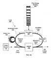
- FIG. 1Ais a block diagram illustrating various embodiments of a chirped pulse system generally designated 100 .
- the chirped pulse system 100includes a pulse source 110 , an optional multi-pass stretcher 120 , an amplifier 130 and an optional multi-pass compressor 140 .
- the pulse source 110is configured to generate a pulse having a duration, amplitude, mode, and phase profile.
- the pulse source 110comprises, for example, a ring laser, a laser oscillator, a chirped pulse source, a quasi-continuous wave laser, or the like.
- the pulse source 100generates a chirped pulse.
- multi-pass stretcher 120is optional.
- Chirped pulse system 100includes at least one of the multi-pass stretcher 120 and the multi-pass compressor 140 .
- the multi-pass stretcher 120is replaced by a single-pass stretcher of the prior art.
- These embodimentsinclude the multi-pass compressor 140 .
- the multi-pass stretcher 120is configured to receive the pulse from the pulse source 110 and includes one or more Bragg gratings through which the pulse is directed one or more times.
- the pulsetraverses at least one Bragg grating multiple times, and may pass through multiple Bragg gratings one or more times each.
- the Bragg gratingmay be fabricated using a photorefractive glass that has an altered refractive index in areas that have been exposed to UV light. The areas of altered refractive index may be arranged so as to stretch and/or compress a pulse. Optionally, the path of the pulse through the Bragg grating determines whether the pulse is stretched or compressed.
- the Bragg gratingis a chirped volume Bragg grating (CVBG) configured to stretch (or chirp) a pulse.
- CVBGvolume Bragg grating
- the volume Bragg gratingoptionally includes a cross-sectional aspect ratio in which one dimension is significantly larger than another dimension.
- the volume Bragg gratingmay have a cross-sectional height of microns and a cross sectional width on the order of one or more millimeters.
- the volume Bragg gratingmay act as a single mode waveguide in one dimension and as a bulk optic in another dimension.
- the cross-sectional dimensionsmay be in ratios of at least 1:1, 1:5, 1:10, 1:50, 1:100, 1:500, 1:1000, 1:5000, and 1:10,000. Embodiments with aspect ratios greater than 1:1 may be particularly suited for fabrication on a wafer.
- the amplifier 130is configured to receive the stretched pulse from the multi-pass stretcher 120 and amplify the pulse. In some embodiments, the amplifier 130 is configured to amplify the pulse between passes through a Bragg grating of the multi-pass stretcher 120 . In various embodiments, the amplifier 130 includes a doped fiber amplifier, a semiconductor optical amplifier, a double-clad fiber amplifier, a photonic crystal fiber amplifier, Raman amplifier, and/or the like. In some embodiments, the amplifier 130 comprises a tapered fiber bundle amplifier. Further details of an amplifier including a tapered fiber bundle may be found within U.S. Provisional Patent Application Ser. No.
- the amplifiercomprises a high order mode fiber amplifier such as that described in U.S. patent application Ser. No. 11/491,219, entitled “High Order Mode Optical Amplifier in an Ultrashort Pulse Laser System.”
- the multi-pass compressor 140is configured to receive the amplified pulse from the amplifier 130 and includes one or more Bragg gratings configured to receive the amplified pulse one or more times.
- the amplified pulsetraverses at least one Bragg grating multiple times, and may pass through multiple Bragg gratings one or more times each.
- the temporal dispersion caused by the Bragg gratingmay be controlled by stretching the Bragg grating using a mechanical stretcher or a temperature controller.
- the Bragg gratingis a volume Bragg grating its dispersion properties may be controlled by heating or cooling the volume Bragg grating.
- the multi-pass compressor 140is replaced by a single-pass compressor of the prior art. These embodiments include the multi-pass stretcher 120 .
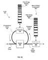
- FIG. 1Bis a block diagram illustrating various embodiments of a chirped pulse system generally designated 101 and including a tunable multi-pass compressor.
- the chirped pulse system 101 in FIG. 1Bdiffers from the chirped pulse system 100 in FIG. 1A in that the chirped pulse system 101 includes a tunable multi-pass compressor 150 and/or an optional second stage compressor 160 .
- the chirped pulse system 101is an alternative embodiment of the Chirped pulse system 100 .
- the tunable multi-pass compressor 150 and/or an optional second stage compressor 160represent alternative embodiments of the multi-pass compressor 140 .
- the tunable multi-pass compressor 150is configured to be tuned by controlling the number of passes of the pulse through a Bragg grating, and thus, controlling the output pulse width.
- the tunable multi-pass compressor 150is configured to provide fine control of the pulse width and the second stage compressor 160 is configured to provide coarse compression.
- the second stage compressor 160includes a single pass compressor or a multi-pass compressor.
- the second stage compressor 160optionally includes a Bragg grating, e.g. a fiber Bragg grating or a Bragg waveguide.
- chirped pulse system 101is configured such that the second stage compressor 160 receives a pulse from the amplifier 130 and the output of the second stage compressor 160 is received by the tunable multi-pass compressor 150 . In these embodiments, the pulse may be substantially compressed prior to being received by the tunable multi-pass compressor 150 .
- FIG. 2is a block diagram illustrating part of chirped pulse system 100 , according to various embodiments. These embodiments include a multi-pass Bragg grating in which the pulse is both stretched and compressed.
- a chirped pulse amplifierincludes a single Bragg grating which is used for both stretching a pulse using multiple passes and for compressing a pulse using multiple passes.
- the path of the pulse through a multi-pass Bragg gratingdetermines whether the pulse is stretched or compressed.
- the pulsemay be directed through a multi-pass stretching path in the Bragg grating for stretching the pulse. Further, the pulse may be directed through a multi-pass compression path in the same Bragg grating resulting in compression of the pulse.
- the embodiments illustrated in FIG. 2include a chirped pulse amplifier 200 including a multi-pass Bragg grating 220 in which the pulse is both stretched and compressed, according to various embodiments.
- the chirped pulse amplifier 200includes embodiments of the multi-pass stretcher 120 , the amplifier 130 and the multi-pass compressor 140 .
- the chirped pulse amplifier 200includes beam steering optic components 210 , a multi-pass Bragg grating 220 , and the amplifier 130 .
- the multi-pass Bragg grating 220is part of both multi-pass stretcher 120 and multi-pass compressor 140 .
- a pulse 205from pulse source 110 , is directed through a stretching path 212 in the multi-pass Bragg grating 220 using one or more beam steering optics 210 .
- the beam steering optics 210include beam splitters, optical fibers, phase rotators, prisms, reflectors, lenses, tapered fiber bundles, Bragg waveguides, optical combiners, and/or the like.
- the multi-pass Bragg grating 220is configured to receive the pulse 205 and output a stretched pulse 215 .
- the beam steering optics 210are configured to further direct the stretched pulse 215 again into the stretching path 212 in the multi-pass Bragg grating 220 for additional stretching. After being stretched two or more times the multi-pass Bragg grating 220 outputs the stretched pulse 215 as a multiply-stretched pulse 225 .
- the multiply-stretched pulse 225may be directed using one or more beam steering optics 210 to the amplifier 130 .
- the amplifier 130is configured to amplify the multiply stretched pulse 225 and output an amplified pulse 235 , as described elsewhere herein.
- the amplified pulse 235may be directed, using beam steering optics 210 , to the multi-pass Bragg grating 220 for compression.
- the beam steering optics 210are further configured to direct the amplified pulse 235 into a compression path 242 in the multi-pass Bragg grating 220 for generating a compressed pulse 245 , and to direct the compressed pulse 245 again into the compression path 242 in the multi-pass Bragg grating 220 for additional compression. After being compressed two or more times the compressed pulse 245 is output as a multiply-compressed pulse 255 .
- the pulse 205 , the stretching path 212 and the compression path 242are depicted as spatially offset for purposes of illustration. However, a practitioner with ordinary skill in the art will recognize that in some embodiments, there may not be a spatial offset between the stretching path 212 and the compression path 242 and that they may overlap within the multi-pass Bragg grating 220 .
- the multi-pass Bragg grating 220 , the amplifier 130 , the pulse source 110 , and/or the one or more of the beam steering optics 210may be mounted and/or fabricated on a wafer.
- FIG. 3is a block diagram of alternative embodiments of the chirped pulse amplifier of FIG. 1A , illustrating details of a multi-pass stretcher and a multi-pass compressor.
- beam steering opticsare used for directing a pulse through multiple paths within volume Bragg gratings to stretch and/or compress the pulse.
- the multiple paths through a volume Bragg gratingmay be separated in space using the beam steering optics.
- the multi-pass stretcher 120includes an optional lens 310 , beam steering optics 210 , and an optional first volume Bragg grating 320 configured to stretch a pulse 305 multiple times.
- the multi-pass compressor 140includes an optional lens(es) 310 , beam steering optics 210 and a second optional volume Bragg grating 320 ′ configured to compress an amplified pulse 335 multiple times.
- the pulse source 110is configured to provide a pulse 305 .
- the lens 310may be used to configure the pulse 305 to converge or diverge.
- the pulse 305may be directed to the first volume Bragg grating 320 using one or more beam steering optics 210 .
- the first volume Bragg grating 320is configured to receive the pulse 305 from the pulse source 110 and output a stretched pulse 315 .
- the stretched pulse 315may be directed, using the beam steering optics 210 , into the first volume Bragg grating 320 again for additional stretching.
- the stretched pulse 315may be further stretched one or more times in the first volume Bragg grating 320 and output as a multiply-stretched pulse 325 .
- the multiply-stretched pulse 325may be directed using one or more beam steering optics 210 to the amplifier 130 .
- the amplifier 130is configured to amplify the multiply stretched pulse 325 and output an amplified pulse 335 .
- the amplified pulse 335may be directed, using beam steering optics 210 and/or a lens(es) 310 , to the second volume Bragg grating 320 ′.
- the second volume Bragg grating 320 ′is configured to receive the amplified pulse 335 from the amplifier 130 and output a compressed pulse 345 .
- the compressed pulse 345may be directed, using one or more beam steering optics 210 , into the second volume Bragg grating 320 ′ again for additional compression.
- the compressed pulse 345may be further compressed one or more times in the second multi-pass Bragg Grating 320 ′ and output as a multiply-compressed pulse 355 .
- the volume Bragg gratings 320 and/or 320 ′, the amplifier 130 , pulse source 110 , one or more lenses 310 and/or the one or more of the beam steering optics 210may be mounted and/or fabricated on a wafer.
- the volume Bragg gratings 320 and 320 ′are illustrated in FIG. 3 as single gratings. However, the volume Bragg gratings 320 and/or 320 ′ may be configured as multiple gratings, configured to receive one or more passes of a pulse. In some embodiment, at least one of the volume Bragg gratings 320 and/or 320 ′ is configured to receive two or more passes of a pulse.
- FIG. 4is a block diagram illustrating further details of the multi-pass compressor 140 of FIG. 1A , according to various embodiments including a multi-pass Bragg grating.
- a pulseis received by a volume Bragg grating at an incident angle configured such that the pulse passes through a path including multiple reflections along the interior of the volume Bragg grating. The number of reflections may be determined from the incident angle of the pulse and the width of the volume Bragg grating.
- a lensmay be disposed in the path of the incident pulse and configured to provide for conditioning the pulse, e.g. adjusting convergence or divergence of the pulse.
- the multi-pass compressor 140includes beam steering optics 210 , an optional lens 310 , a volume Bragg grating 430 , and an optional volume Bragg grating 440 .
- the pulse source 110is configured to emit an incident pulse 405 and the beam steering optics 210 are configured to direct the incident pulse 405 toward the volume Bragg grating 430 at an incident angle 410 with respect to a normal 460 to a plane of the volume Bragg grating 430 .
- An optional lens 310is configured to provide for divergence or convergence of the incident pulse 405 .
- the incident pulse 405enters the volume Bragg grating 430 through an aperture 420 .
- the aperture 420is normal to the incident pulse 405 .
- the incident pulse 405is compressed to generate a compressed pulse 415 .
- the optional volume Bragg grating 440is configured to both further compress the compressed pulse 415 and to reflect the compressed pulse 415 into the volume Bragg grating 430 for additional compression.
- the compressed pulse 415may undergo multiple reflections within the volume Bragg gratings 430 and 440 , through an appropriate angle 410 . With each reflection, the compressed pulse 415 is further compressed.
- the compressed pulse 415may be emitted as a multiply compressed pulse 425 from the volume Bragg grating 430 at an aperture 450 .
- the number of reflections within the volume Bragg grating 430may be dependent on the length of the volume Bragg grating 430 and/or the volume Bragg grating 440 . A greater length will result in a greater number of reflections.
- the volume Bragg grating 430 and the volume Bragg grating 440may be configured to emit the multiply compressed pulse 425 from the volume Bragg grating 440 instead of 430 .
- the length of the volume Bragg gratings 430 and/or 440may be used to control the number of reflections.
- the number of reflections within the volume Bragg grating 430may also be dependent on the angle 410 .
- a smaller angle 410may result in a greater number of reflections.
- the number of the reflections of the compressed pulse 415and therefore the width of the output pulse, may be tuned by adjusting the incident angle 410 .
- a reflectoris disposed in place of the volume Bragg grating 440 .
- These embodimentsoptionally include a movable embodiment of aperture 450 disposed within the reflector.
- the number of reflections that a pulse experiencesmay be controlled by positioning the aperture 450 .
- the aperture 450may be positioned such that the compressed pulse 415 is reflected nine times before reaching the aperture 450 , or the aperture 450 may be positioned such that the compressed pulse 415 is reflected eleven times before reaching the aperture 450 .
- the aperture 450is movable to select between one and thirty-five reflections.
- the number of reflections, and the amount of compressioncan be controlled by positioning the aperture 450 .
- the volume Bragg gratings 430 and 440are configured to compress the incident pulse 405 .
- the volume Bragg gratings 430 and 440may be configured to stretch the pulse 405 .
- the volume Bragg grating 430 and/or 440 , the lens 310 , the beam steering optics 210 , and/or the pulse source 110may be mounted and/or fabricated on a wafer.
- multiple passes within a Bragg gratingmay be accomplished by directing a pulse through multiple paths that are spatially separated, to stretch or compress the pulse.
- the multiple paths through the Bragg gratingmay be separated in time instead of position.
- the separation in time of the multiple paths through the Bragg gratingmay be accomplished using a switch.
- the switchmay be used to select the number of passes through the Bragg grating, thus, determining the width of the stretched or compressed pulse.
- a switchcan be an optical switch, such as an acousto-optic modulator (AOM) switch, an electro-optic modulator (EOM) switch, or a 2 ⁇ 2 switch, or a mechanical switch such as a movable micro mirror, and/or the like.
- AOMacousto-optic modulator
- EOMelectro-optic modulator
- 2 ⁇ 2 switcha mechanical switch such as a movable micro mirror, and/or the like.
- FIG. 5Ais a block diagram illustrating further details of the multi-pass stretcher 120 of FIG. 1A , according to various embodiments including a multi-pass loop 500 .
- the loop 500includes a switch 520 , a circulator 540 , a fiber Bragg grating 550 , and an optional delay line 560 .
- amplifier 130is included within loop 500 . In other embodiments, amplifier 130 is separate from loop 500 .
- the switch 520is configured to receive a pulse 515 from the pulse source 110 and direct a switched pulse 525 to the amplifier 130 .
- the amplifiermay be configured to receive the switched pulse 525 and output an amplified pulse 535 .
- the amplified pulse 535may be directed to the circulator 540 .
- the circulator 540is configured to direct the amplified pulse 535 into the fiber Bragg grating 550 or other Bragg grating.
- the fiber Bragg grating 550is configured to receive the amplified pulse 535 from the circulator 540 and return a stretched pulse 545 to the circulator 540 .
- the circulator 540is further configured to direct the stretched pulse 545 to the delay line 560 .
- the delay line 560is configured to output a delayed pulse 555 to the switch 520 .
- the same pulsecan be directed around the loop 500 (i.e., from the switch 520 , through the amplifier 130 , the circulator 540 , the fiber Bragg grating 550 and the delay line 560 ) multiple times.
- a delayed pulse received at the switch 520can be directed again to the circulator 540 .
- the pulseis again (optionally) amplified by the amplifier 130 , and further stretched as a result of being directed into and out of the fiber Bragg grating 550 .
- the state of the switch 520may be changed such that the delayed pulse 555 is directed as an output pulse 565 , rather than towards the amplifier 130 and/or circulator 540 .
- the switch 520may be used to control the number of times the pulse is directed through the loop 500 .
- the switch 520includes a counter, a timer, a sensor, and/or the like.
- the countermay be configured to count the number of times the compressed pulse is direct into the fiber Bragg grating 550 .
- the timermay be used to measure a delay time between changes in the state of the switch 520 .
- the amount of stretching applied to the pulsecan be tuned by controlling the number of times the pulse is directed through the elements in the loop 500 .
- the output pulse width of the loop 500may be tuned by opening or closing the switch 520 at appropriate times.
- the loop 500is designed to stretch the pulse using from one to one hundred passes, such that the width of the output pulse 565 may be tunable to one hundred different pulse widths.
- the loop 500may be configured for selection of more or fewer than one hundred passes.
- the loop 500may be used to stretch the pulse at least 1, 2, 10, 30, 100, or more times.
- the pulseis attenuated, for example two percent, with each pass through the loop 500 .
- the pulsewill be attenuated about fifty percent after thirty-four passes.
- the pulsemay be amplified between passes, for example using the amplifier 130 , to compensate, or more than compensate, for the attenuation.
- the pulses 515 , 525 , 535 , 545 , and/or 555may be communicated between the switch 520 , the amplifier 130 , the circulator 540 , the fiber Bragg grating 550 , and/or the delay line 560 using beam steering optics described elsewhere herein.
- a fiber optic, a high order mode fiber optic, and/or a tapered fiber bundlemay be used to direct a pulse between any elements of the loop 500 , e.g., the switch 520 and the amplifier 130 , the amplifier 130 and the circulator 540 , the circulator 540 and the fiber Bragg grating 550 , the circulator 540 and the delay line 560 , and/or the delay line 560 and the switch 520 .
- FIG. 5Bis a block diagram illustrating further details of the multi-pass stretcher of FIG. 1A , according to various embodiments including a Bragg waveguide 570 .
- FIG. 5Bdiffers from FIG. 5A in that a Bragg waveguide 570 is used to stretch the pulse, instead of the circulator 540 and the fiber Bragg grating 550 .
- the pulseis further stretched as a result of passing through the Bragg waveguide 570 , instead of being directed into the fiber Bragg grating 550 by the circulator 540 .
- FIG. 5Cis a block diagram illustrating further details of the multi-pass stretcher of FIG. 1A , according to various embodiments including a Bragg waveguide 570 and a reflector 580 .
- FIG. 5Bdiffers from FIG. 5A in that a Bragg waveguide 570 and a reflector 580 is used to stretch the pulse, instead of the fiber Bragg grating 550 .
- the pulseis further stretched as a result of being directed into the fiber Bragg waveguide 570 by the circulator 540 .
- the reflector 580may return the pulse back through the Bragg waveguide 570 to the circulator 540 .
- the fiber Bragg grating 550 and Bragg waveguideare used configured to stretch a pulse.
- the fiber Bragg grating 550may be configured to compress a pulse.
- the pulsemay be compressed multiple times in one Bragg grating for fine adjustment and compressed a large amount one time in another Bragg grating for a coarse adjustment.
- Embodiments of the loop 500 that are configured to compress a pulsetypically do not include the amplifier 130 .
- FIG. 5Dis a block diagram illustrating details of the tunable multi-pass compressor 150 and second stage compressor 160 of FIG. 1B , according to various embodiments including a multi-pass loop 500 .
- FIG. 5Ddiffers from FIG. 5 A in that the embodiments of loop 500 illustrated are configured to compress the pulse instead of stretch the pulse, and a second stage compressor 502 comprising a fiber Bragg grating 550 ′ is configured for further compressing the output pulse 565 .
- FIG. 5Dfurther differs from FIG. 5A in that the optional amplifier 130 and the optional delay line 560 are omitted.
- the loop 500includes the switch 520 , the circulator 540 , and the fiber Bragg grating 550 .
- the loop 500may further include the delay line 560 when configured for compressing a pulse.
- the pulsecan be compressed multiple times.
- the same pulsecan be directed around the loop 500 (i.e., from the switch 520 , through the circulator 540 , the fiber Bragg grating 550 and back to the switch 520 ) multiple times.
- a pulse received at the switch 520can be directed again to the circulator 540 .
- the pulse againis directed into and out of the fiber Bragg grating 550 and thus, further compressed.
- the state of switch 520may be changed such that the compressed pulse 545 is directed as an output pulse 565 , rather than towards the circulator 540 .
- the compression of the pulsemay be tunable.
- the amount of compressing experienced by the pulse, and thus, the pulse widthcan be tuned by controlling the number of times the pulse is directed through the loop 500 , using the switch 520 .
- the output pulse width of the loop 500may be tuned by opening or closing the switch 520 at appropriate times.
- the loop 500may be designed to compress the pulse using from one to one hundred passes, such that the width of the output pulse 565 may be tunable to one hundred available pulse widths.
- the loop 500may be configured for selection of more or fewer than one hundred passes.
- the loop 500may be used to compress the pulse at least 1, 2, 10, 30, 100, or more times.
- the pulseis attenuated, for example two percent, each pass through the loop 500 . When the attenuation is two percent per pass, the pulse will be attenuated about fifty percent after thirty-four passes.
- the second stage compressor 502comprises a circulator 540 and the fiber Bragg grating 550 ′ and is disposed to compress the output pulse 565 .
- the fiber Bragg grating 550 ′ in the second stage compressor 502is configured to compress the pulse by a greater degree than a single pass through the fiber Bragg grating 550 in the loop 500 .
- the loop 500may be used for fine adjustment of the compression of the pulse, whereas the second stage compressor 502 may be used for large scale compression of the pulse.
- a multi-pass Bragg grating(e.g., a volume Bragg grating) may be used in the second stage compressor 502 instead of the fiber Bragg Grating 550 ′, for greater compression of the output pulse 565 .
- a volume Bragg grating, Bragg waveguide, or other Bragg gratingmay be substituted for the fiber Bragg grating 550 and/or the fiber Bragg grating 550 ′.
- the switch 520 , the amplifier 130 , the circulator 540 , the fiber Bragg grating 550 , the delay line 560 , the pulse source 110 , and/or beam steering optic componentsmay be mounted and/or fabricated on a wafer.
- FIG. 6is a block diagram illustrating details of the multi-pass stretcher 120 of FIG. 1A , including one or more multi-pass path 600 , according to various embodiments.
- the multi-pass stretcher 120includes one or more beam steering optics 210 , a volume Bragg grating 640 , a switch 650 , an optional delay line 560 and an optional volume Bragg grating 640 ′, which may be disposed to form the path 600 for a pulse 615 .
- the volume Bragg grating 640 and/or 640 ′could be replaced by a fiber Bragg grating or any other Bragg waveguide.
- the beam steering optic 210is configured to receive the pulse 615 from the pulse source 110 and direct the pulse 615 to the volume Bragg grating 640 .
- the volume Bragg grating 640may be configured to stretch the pulse 615 and return a stretched pulse 625 , via the beam steering optics 210 , the switch 650 , and the delay line 560 , to the volume Bragg grating 640 ′.
- the volume Bragg grating 640 ′may further stretch the stretched pulse 625 and return the stretched pulse 625 to the switch 650 via the delay line 560 .
- the volume Bragg grating 640is replaced by a reflecting element. In these embodiments, Volume Bragg grating 640 may be used alone to stretch the Pulse 615 .
- the stretched pulse 625may be directed through the path 600 multiple times in a first state of the switch 650 , thus, producing a multiply stretched pulse.
- the switch 650may direct the stretched pulse 625 through the path 600 to the volume Bragg grating 640 again.
- the stretched pulse 625is directed out of the path 600 as an output pulse 635 .
- the switch 650is configured to adjust the polarization of the pulse in order to control whether it is again directed into the volume Bragg grating 640 or directed as output.
- the stretched pulse 625is again directed in and out of the volume Bragg grating 640 and 640 ′ and thus, further stretched.
- the delay line 560may be used to control distortion as the length of the stretched pulse 625 increases.
- the embodiments of the multi-pass stretcher 120 illustrated in FIG. 6can include an embodiment of Amplifier 130 configured to amplify the stretched pulse 625 between passes though the volume Bragg grating 640 and/or volume Bragg grating 640 ′.
- the width of the output pulse 635may be tunable.
- the amount of further stretching applied to the stretched pulse 625and thus, the width of the output pulse 635 , can be tuned by controlling the number of times the stretched pulse 625 is directed through the elements in the path 600 .
- the output pulse width of the path 600may be tuned by changing the states of the switch 650 at appropriate times.
- the path 600may be configured to stretch the pulse 615 using from one to one hundred passes such that the width of the output pulse 635 may be tunable to select one of one hundred available pulse widths.
- the switchmay be configured for selection from more or fewer than one hundred passes.
- the stretched pulse 625may be directed between the switch 650 , the volume Bragg grating 640 and 640 ′, and/or the delay line 560 using beam steering optics 210 described elsewhere herein.
- an optic fiberfor example a tapered fiber bundle, may be used to direct a pulse between any elements of the path 600 , e.g., the switch 650 , the volume Bragg grating 640 and 640 ′, the delay line 560 and/or other beam steering optics 210 .
- the volume Bragg grating 640 and/or 640 ′are illustrated as configured to stretch the pulse 615 .
- the volume Bragg grating 640 and/or 640 ′may be configured to compress the pulse 615 in the path 600 instead of stretch the pulse 615 .
- such a path 600 configured to compress a pulsemay be coupled to a second stage compressor, such as that illustrated in FIG. 5D .
- a volume Bragg grating or Bragg waveguide plus a reflectormay be substituted for the volume Bragg grating 640 and/or 640 ′.
- the volume Bragg grating 640 and/or 640 ′, the switch 650 , the delay line 560 , the beam steering optics 210 and/or the pulse source 110may be mounted and/or fabricated on a wafer.
- Various embodimentsinclude methods for stretching or compressing a pulse including directing the pulse through a Bragg grating multiple times. The multiple passes through the Bragg grating result in further stretching or compression of the pulse to create multiply stretched or multiply compressed pulses.
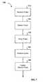
- FIG. 7is a block diagram illustrating a method 700 for stretching a pulse, according to various embodiments.
- a pulseis received by a Bragg grating (e.g., the fiber Bragg grating 550 , the volume Bragg grating 320 , Bragg waveguide 570 , and/or the like) from a pulse source.
- Beam steering opticse.g., the beam steering optics 210
- the beam steering opticsinclude a lens configured to produce a converging or diverging pulse.
- the beam steering opticsare configured to rotate the pulse, split the pulse, amplify the pulse, delay the pulse, switch the pulse, reflect the pulse, modify polarization of the pulse, and/or the like.
- a pulse(e.g., pulse 205 ) is stretched by a Bragg grating (e.g., Bragg grating 220 ) to produce a stretched pulse 215 .
- the path that the pulse followse.g., the stretching path 212 or the compression path 242 ) into and out of the Bragg grating 220 determines whether the pulse is stretched compressed.
- the beam steering opticse.g., beam steering optics 210
- the length of the stretched pulse 215may approach the length of the stretching path 212 into and out of the Bragg grating 220 as the stretched pulse 215 is stretched.
- the stretched pulse 215is delayed to avoid distortion, truncation and/or the like.
- the step 730further includes amplifying the stretched pulse 215 .
- the amount of stretching possibleis limited by a length of a delay line, such as delay line 560 .
- the stretched pulse 215is amplified instead of delayed in step 730 .
- the stretched pulse 215is redirected to the Bragg grating 220 using beam steering optics 210 .
- the stretched pulse 215is redirected to the stretching path 212 through the Bragg grating 220 configured to stretch the stretched pulse 215 again.
- the stretched pulse 215is stretched further using the Bragg grating 220 , to produce a multiply stretched pulse.
- the method 700includes further stretching the stretched pulse 215 in the same Bragg grating 220 .
- multiple paths of the stretched pulse 215 through the Bragg grating 220can be separated spatially.
- the beam steering optics 210may be used to provide the spatial separation of the paths.
- the multiple paths of the stretched pulse 215 through a fiber Bragg grating 220may be separated in the time domain, using beam steering optics 210 , including a switch, e.g. the switch 520 illustrated in FIG. 5A .
- the method 700includes directing the stretched pulse 215 into separate Bragg gratings 220 .
- the method 700 for stretching a pulseis described as being comprised of various steps (e.g., receiving a pulse 710 , stretching the pulse 720 , delaying the pulse 730 , redirecting the pulse 740 , and further stretching the pulse 750 ), fewer or more steps may comprise the method 700 and still fall within the scope of various embodiments. For example, steps 730 - 750 may be repeated multiple times.
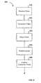
- FIG. 8is a block diagram illustrating a method 800 for compressing a pulse through spatially separated multiple paths, according to one embodiment.
- the steps 810 - 850are similar to the steps 710 - 750 respectively, except that the pulse is compressed instead of stretched.
- a pulse(e.g., the pulse 235 ) is received by the Bragg grating 220 .
- the pulse 235is compressed by the Bragg grating 220 .
- the beam steering optics. 210are configured to direct the pulse 235 through the compression path 242 in the Bragg grating 220 .
- a compressed pulsee.g., the compressed pulse 245 is delayed.
- the compressed pulse 245is redirected, using the beam steering optics 210 , to the compression path 242 through the Bragg grating 220 for further compression.
- the compressed pulse 245is further compressed using the Bragg grating 220 , to generate a multiply compressed pulse.
- the pulse 235can be compressed by the same Bragg grating 220 used for stretching an input pulse 205 , using the beam steering optics 210 to select the stretching path 212 or the compression path 242 , as described elsewhere herein.
- the amount of compression that is possibleis limited by the length of a delay line, such as delay line 560 .
- the method 800 for stretching a pulseis described as being comprised of various steps (e.g., receiving a pulse in step 810 , compressing the pulse in step 820 , delaying the pulse in step 830 , redirecting the pulse in step 840 , and further compressing the pulse in step 850 ), fewer or more steps may comprise the method 800 and still fall within the scope of various embodiments. For example, the steps 840 and 850 may be repeated multiple times.
- the width of a stretched or compressed pulsemay be tuned by turning a switch on or off at appropriate times.
- the number of passes through a grating for stretching or compressing the pulsemay be controlled using the switch to direct the pulse into the grating multiple times, or away from the grating.
- the switchcan be used to control the width of the stretched or the compressed pulse.
- FIG. 9is a block diagram of a method 900 of tuning the stretching of a pulse, according to various embodiments.
- a pulsee.g., the pulse 515
- a fiber Bragg gratinge.g., the fiber Bragg grating 550
- the pulse 515may be directed to the fiber Bragg grating using beam steering optics 210 .
- the pulse 515is stretched using the fiber Bragg grating 550 .
- a step 930includes determining if a loop time has elapsed.
- the loop timeis a time a pulse has been in a loop such as loop 500 .
- the longer the loop timemore times a pulse will have passed through a Bragg grating configured to stretch the pulse. Thus, the longer the loop time, the greater the stretching that will occur.
- a timermay be coupled to the switch 520 and set to change the state of the switch 520 after a predetermined loop time has elapsed. If the loop time has not elapsed, the stretched pulse 545 is directed, e.g., using the switch 520 , to be stretched again.
- the stretched pulse 545is delayed. As the length of the stretched pulse increases, as a result of multiple stretching steps, the delay may be useful in accommodating longer stretched pulses 545 from the fiber Bragg grating 550 and/or associated beam steering optics 210 to prevent truncation of the stretched pulse 545 when the switch 520 is changed to direct the stretched pulse 545 as output.
- the step 940further includes amplifying the stretched pulse 545 .
- the stretched pulse 545is amplified instead of delayed in step 940 .
- the stretched pulse 545may be stretched again in step 920 , to generate a multiply stretched pulse.
- step 940is omitted and the stretched pulse 545 is stretched again at step 920 , directly after step 930 .
- the stretched pulse 545may be stretched multiple times in a loop comprising the steps 920 , 930 , and 940 .
- the switch 520may change state and the stretched pulse 545 is output at step 950 .
- a sensordetermines a property of the output pulse.
- the property determined by the sensor in step 960includes the length of the stretched pulse 545 , the intensity of the stretched pulse 545 , the power of the stretched pulse 545 , a wavelength of the stretched pulse 545 , and/or the like.
- the loop timeis changed based on the property determined in step 960 .
- the method 900 for stretching a pulseis described as being comprised of various steps (e.g., receiving a pulse in step 910 , stretching the pulse in step 920 , determining if the loop time has elapsed in step 930 , delaying the pulse in step 940 , outputting the pulse in step 950 ), and sensing a property of the stretched pulse in step 960 , fewer or more steps may comprise the method 900 and still fall within the scope of various embodiments.
- FIG. 10is a block diagram illustrating a method 1000 of tuning the compression of a pulse, according to various embodiments.
- the steps 1010 - 1060are similar to the steps 910 - 960 respectively, except where the method 1000 of FIG. 10 differs from the method of FIG. 9 in that the pulse is compressed instead of stretched, using multiple passes through s Bragg grating.
- steps 1020 - 1050may be used for fine compression adjustment and a second stage compressor may follow step 1050 for coarse compression.
- the Bragg gratingcan be tuned mechanically, thermally, or using a piezo device.
- optically compression or expansion devicesother than Bragg gratings may be used.
- the systems and methods disclosed herein with reference to stretching a pulsemay be adapted by one of ordinary skill in the art to compressing a pulse.
- the systems and methods disclosed herein with reference to compressing a pulsemay be adapted by one of ordinary skill in the art to stretching a pulse.
- those examples including a fiber Bragg grating or volume Bragg gratingmay be adapted by reversing direction of the grating.
- those examples including a Bragg waveguidemay be adapted by changing the characteristics of the Bragg waveguide.
- the systems and methods described hereinmay be adapted to other types of pulse stretching and compressing optics, other than Bragg gratings.
Landscapes
- Physics & Mathematics (AREA)
- Electromagnetism (AREA)
- Engineering & Computer Science (AREA)
- Plasma & Fusion (AREA)
- Optics & Photonics (AREA)
- Optical Modulation, Optical Deflection, Nonlinear Optics, Optical Demodulation, Optical Logic Elements (AREA)
- Lasers (AREA)
Abstract
Description
- U.S. Provisional Patent Application Ser. No. 60/761,736, filed on Jan. 23, 2006, entitled “METHOD OF DISPERSION COMPENSATION IN A CPA SYSTEM,”
- U.S. Provisional Patent Application Ser. No. 60/762,284, filed on Jan. 25, 2006, entitled “USP LASER FIBER AMPLIFIER,”
- U.S. Provisional Patent Application Ser. No. 60/763,002, filed on Jan. 26, 2006, entitled “SEED CONTROL IN ULTRA-SHORT PULSE LASER SYSTEMS,”
- U.S. Provisional Patent Application Ser. No. 60/762,791, filed on Jan. 26, 2006, entitled “AMPLIFIER CONTROL IN ULTRA-SHORT PULSE LASER SYSTEMS” and
- U.S. Provisional Patent Application Ser. No. 60/762,790, filed on Jan. 26, 2006, entitled “METHOD OF REMOTE ACCESS TO AN ULTRA-SHORT PULSE LASER SYSTEM.”
- co-pending U.S. patent application entitled “Bragg Fibers in Systems for the Generation of High Peak Power Light,” Ser. No. 11/112,256, filed Apr. 22, 2005, which in turn claims the benefit and priority of U.S. provisional patent application Ser. Nos. 60/635,734, filed on Dec. 13, 2004, and entitled “Bragg Fibers For The Generation Of High Peak Power Light,” and 60/636,376, filed on Dec. 16, 2004, and entitled “Bragg Fibers In Systems For The Generation Of High Peak Power Light;” and
- co-pending U.S. patent application entitled “High Order Mode Optical Amplifier in an Ultrashort Pulse Laser System,” Ser. No. 11/491,219, filed on Jul. 20, 2006, which in turn claims the benefit and priority of U.S. Provisional Patent Application entitled “Chirped Pulse Amplifier System Including Tapered Fiber Bundle,” Ser. No. 60/793,960, filed on Apr. 20, 2006.
- The disclosures of all of the above U.S. patents and patent applications are incorporated by reference herein.
Claims (28)
Priority Applications (7)
| Application Number | Priority Date | Filing Date | Title |
|---|---|---|---|
| US12/259,176US8139910B2 (en) | 2006-01-23 | 2008-10-27 | Systems and methods for control of ultra short pulse amplification |
| US12/363,646US9130344B2 (en) | 2006-01-23 | 2009-01-30 | Automated laser tuning |
| US12/363,636US20090216494A1 (en) | 2006-01-23 | 2009-01-30 | Network Laser System with Remote Diagnostics |
| PCT/US2009/005854WO2010051022A1 (en) | 2008-10-27 | 2009-10-27 | Network laser system with remote diagnostics |
| EP09823931AEP2377210A1 (en) | 2008-10-27 | 2009-10-27 | Network laser system with remote diagnostics |
| EP20090829443EP2380250A1 (en) | 2008-10-27 | 2009-10-27 | Automated laser tuning |
| PCT/US2009/005853WO2010062342A1 (en) | 2008-10-27 | 2009-10-27 | Automated laser tuning |
Applications Claiming Priority (7)
| Application Number | Priority Date | Filing Date | Title |
|---|---|---|---|
| US76173606P | 2006-01-23 | 2006-01-23 | |
| US76228406P | 2006-01-25 | 2006-01-25 | |
| US76279006P | 2006-01-26 | 2006-01-26 | |
| US76279106P | 2006-01-26 | 2006-01-26 | |
| US76300206P | 2006-01-26 | 2006-01-26 | |
| US11/615,883US7444049B1 (en) | 2006-01-23 | 2006-12-22 | Pulse stretcher and compressor including a multi-pass Bragg grating |
| US12/259,176US8139910B2 (en) | 2006-01-23 | 2008-10-27 | Systems and methods for control of ultra short pulse amplification |
Related Parent Applications (1)
| Application Number | Title | Priority Date | Filing Date |
|---|---|---|---|
| US11/615,883DivisionUS7444049B1 (en) | 2006-01-23 | 2006-12-22 | Pulse stretcher and compressor including a multi-pass Bragg grating |
Related Child Applications (1)
| Application Number | Title | Priority Date | Filing Date |
|---|---|---|---|
| US11/740,874Continuation-In-PartUS8232687B2 (en) | 2006-01-23 | 2007-04-26 | Intelligent laser interlock system |
Publications (2)
| Publication Number | Publication Date |
|---|---|
| US20090323740A1 US20090323740A1 (en) | 2009-12-31 |
| US8139910B2true US8139910B2 (en) | 2012-03-20 |
Family
ID=39874363
Family Applications (2)
| Application Number | Title | Priority Date | Filing Date |
|---|---|---|---|
| US11/615,883ActiveUS7444049B1 (en) | 2006-01-23 | 2006-12-22 | Pulse stretcher and compressor including a multi-pass Bragg grating |
| US12/259,176Expired - Fee RelatedUS8139910B2 (en) | 2006-01-23 | 2008-10-27 | Systems and methods for control of ultra short pulse amplification |
Family Applications Before (1)
| Application Number | Title | Priority Date | Filing Date |
|---|---|---|---|
| US11/615,883ActiveUS7444049B1 (en) | 2006-01-23 | 2006-12-22 | Pulse stretcher and compressor including a multi-pass Bragg grating |
Country Status (1)
| Country | Link |
|---|---|
| US (2) | US7444049B1 (en) |
Cited By (3)
| Publication number | Priority date | Publication date | Assignee | Title |
|---|---|---|---|---|
| US20140153594A1 (en)* | 2012-11-30 | 2014-06-05 | Industrial Technology Research Institute | Apparatus for generating pulse train with adjustable time interval |
| US20170203385A1 (en)* | 2015-03-30 | 2017-07-20 | Jiangsu University | Device and method for laser-inducing cavitation strengthening with multi-system automatic coordination work |
| CN111769428A (en)* | 2020-06-01 | 2020-10-13 | 浙江大学 | An all-fiber high-energy pulse regeneration and amplification device and method based on 2×3 optical switch |
Families Citing this family (38)
| Publication number | Priority date | Publication date | Assignee | Title |
|---|---|---|---|---|
| US8724207B1 (en) | 2000-01-04 | 2014-05-13 | University Of Central Florida Research Foundation, Inc. | Laser pulse temporal, spectral and spatial shaping devices based on volume diffractive gratings with spatially variable parameters |
| US7361171B2 (en) | 2003-05-20 | 2008-04-22 | Raydiance, Inc. | Man-portable optical ablation system |
| US9022037B2 (en) | 2003-08-11 | 2015-05-05 | Raydiance, Inc. | Laser ablation method and apparatus having a feedback loop and control unit |
| US8173929B1 (en) | 2003-08-11 | 2012-05-08 | Raydiance, Inc. | Methods and systems for trimming circuits |
| US8921733B2 (en) | 2003-08-11 | 2014-12-30 | Raydiance, Inc. | Methods and systems for trimming circuits |
| US8135050B1 (en) | 2005-07-19 | 2012-03-13 | Raydiance, Inc. | Automated polarization correction |
| US8189971B1 (en) | 2006-01-23 | 2012-05-29 | Raydiance, Inc. | Dispersion compensation in a chirped pulse amplification system |
| US7444049B1 (en) | 2006-01-23 | 2008-10-28 | Raydiance, Inc. | Pulse stretcher and compressor including a multi-pass Bragg grating |
| US8232687B2 (en) | 2006-04-26 | 2012-07-31 | Raydiance, Inc. | Intelligent laser interlock system |
| US9130344B2 (en) | 2006-01-23 | 2015-09-08 | Raydiance, Inc. | Automated laser tuning |
| US7822347B1 (en) | 2006-03-28 | 2010-10-26 | Raydiance, Inc. | Active tuning of temporal dispersion in an ultrashort pulse laser system |
| US7777940B1 (en)* | 2007-02-09 | 2010-08-17 | University Of Central Florida Research Foundation, Inc. | Extreme chirped pulse amplification and phase control |
| US8036537B2 (en) | 2007-06-13 | 2011-10-11 | International Business Machines Corporation | Optical pulse amplication apparatus and method |
| US7831113B1 (en) | 2007-10-18 | 2010-11-09 | Hrl Laboratories, Llc | Optical pulse position modulator with chirp compensation |
| US7903326B2 (en) | 2007-11-30 | 2011-03-08 | Radiance, Inc. | Static phase mask for high-order spectral phase control in a hybrid chirped pulse amplifier system |
| US20090273828A1 (en)* | 2008-04-30 | 2009-11-05 | Raydiance, Inc. | High average power ultra-short pulsed laser based on an optical amplification system |
| US8125704B2 (en) | 2008-08-18 | 2012-02-28 | Raydiance, Inc. | Systems and methods for controlling a pulsed laser by combining laser signals |
| US9696476B1 (en)* | 2009-05-15 | 2017-07-04 | Optigrate Corporation | Volume Moiré Bragg gratings in a photosensitive material |
| US20110038390A1 (en)* | 2009-07-29 | 2011-02-17 | Lockheed Martin Corporation | Multi-plate composite volume bragg gratings, systems and methods of use thereof |
| FR2953945B1 (en)* | 2009-12-10 | 2011-12-30 | Fastlite | DEVICE FOR THE COMPENSATION OF TIME DISPERSION APPLIED TO THE GENERATION OF ULTRA BRIEF LUMINOUS PULSES. |
| US9054479B2 (en)* | 2010-02-24 | 2015-06-09 | Alcon Lensx, Inc. | High power femtosecond laser with adjustable repetition rate |
| US8279901B2 (en)* | 2010-02-24 | 2012-10-02 | Alcon Lensx, Inc. | High power femtosecond laser with adjustable repetition rate and simplified structure |
| US8855150B2 (en)* | 2010-04-29 | 2014-10-07 | Lockheed Martin Corporation | Tiled bragg grating and laser systems therefrom |
| KR20140018183A (en) | 2010-09-16 | 2014-02-12 | 레이디안스, 아이엔씨. | Laser based processing of layered materials |
| US8554037B2 (en) | 2010-09-30 | 2013-10-08 | Raydiance, Inc. | Hybrid waveguide device in powerful laser systems |
| CN103403983A (en) | 2010-12-30 | 2013-11-20 | 洛克希德马丁公司 | Compact high energy mid wave OPCPA laser |
| WO2013039668A1 (en) | 2011-09-14 | 2013-03-21 | Fianium, Inc. | Methods and apparatus pertaining to picosecond pulsed fiber based lasers |
| US8908739B2 (en)* | 2011-12-23 | 2014-12-09 | Alcon Lensx, Inc. | Transverse adjustable laser beam restrictor |
| DE102016222528A1 (en)* | 2016-11-16 | 2018-05-17 | InnoLas Photonics GmbH | Laser arrangement and a method for optical amplification of ultrashort laser pulses |
| US10862260B2 (en)* | 2017-01-03 | 2020-12-08 | Innoven Energy Llc | Integration of direct compressor with primary laser source and fast compressor |
| US11133637B2 (en)* | 2018-10-26 | 2021-09-28 | The Government Of The United States Of America, As Represented By The Secretary Of The Navy | Apparatus and method for tunable frequency parametric down-conversion of high peak power lasers through dual chirp pulse mixing |
| US11233372B2 (en)* | 2019-06-25 | 2022-01-25 | Lumentum Operations Llc | Femtosecond pulse stretching fiber oscillator |
| CN114389133A (en)* | 2022-03-24 | 2022-04-22 | 广东利元亨智能装备股份有限公司 | Chirp pulse amplification method, laser processing apparatus, and storage medium |
| LT7045B (en) | 2022-06-30 | 2024-02-12 | Uab "Ekspla" | Method for controlling pulse duration and energy of laser radiation, device for implementing the method, and laser system with the integrated device |
| GB2620444A (en) | 2022-07-08 | 2024-01-10 | Coherent Scotland Ltd | Passively double-passed chirped-fiber-Bragg-grating |
| GB2624219A (en) | 2022-11-11 | 2024-05-15 | Coherent Scotland Ltd | Fiber-optic pulse picker and stretcher |
| CN117471720B (en)* | 2023-12-27 | 2024-04-09 | 武汉中科锐择光电科技有限公司 | Ultra-short pulse shaping device based on acousto-optic delay line |
| CN119921166B (en)* | 2025-03-28 | 2025-07-25 | 中国科学院长春光学精密机械与物理研究所 | A high-power pulse width and repetition rate tunable laser |
Citations (474)
| Publication number | Priority date | Publication date | Assignee | Title |
|---|---|---|---|---|
| US2436662A (en) | 1944-09-02 | 1948-02-24 | Gen Electric | Pulse generator |
| US3459960A (en) | 1967-05-02 | 1969-08-05 | Atomic Energy Commission | High energy pulse generator utilizing a decoupling transformer |
| US3549256A (en) | 1968-11-19 | 1970-12-22 | United Aircraft Corp | Laser pulse compression ranging system using double-chirped pulses |
| US3599019A (en) | 1967-08-25 | 1971-08-10 | Nippon Electric Co | Laser device with selective oscillation |
| US3602836A (en) | 1969-04-01 | 1971-08-31 | American Optical Corp | Laser structure with a segmented laser rod |
| US3622907A (en) | 1970-01-27 | 1971-11-23 | United Aircraft Corp | Composite oscillator amplifier laser |
| US3626318A (en) | 1970-03-10 | 1971-12-07 | American Optical Corp | Tandem oscillator disc amplifier with trivalent neodymium input disc and trivalent neodymium plus ytterbium output discs |
| US3628179A (en) | 1969-03-12 | 1971-12-14 | American Optical Corp | Stacked composite plate laser |
| US3631362A (en) | 1968-08-27 | 1971-12-28 | Gen Electric | Face-pumped, face-cooled laser device |
| US3646469A (en) | 1970-03-20 | 1972-02-29 | United Aircraft Corp | Travelling wave regenerative laser amplifier |
| US3654624A (en) | 1969-03-17 | 1972-04-04 | Precision Instr Co | Laser recording system using drum mounted record strips |
| US3696308A (en) | 1970-08-21 | 1972-10-03 | Hadron Inc | Segmented laser apparatus and method of making the same |
| US3735282A (en) | 1972-06-14 | 1973-05-22 | F Gans | Liquid-cooled, segmented glass laser |
| US3806829A (en) | 1971-04-13 | 1974-04-23 | Sys Inc | Pulsed laser system having improved energy control with improved power supply laser emission energy sensor and adjustable repetition rate control features |
| US3808549A (en) | 1972-03-30 | 1974-04-30 | Corning Glass Works | Optical waveguide light source |
| US3851267A (en) | 1972-10-18 | 1974-11-26 | Atomic Energy Commission | Modular disc laser |
| US3942127A (en) | 1975-04-11 | 1976-03-02 | The United States Of America As Represented By The Secretary Of The Navy | Aspheric cassegrain laser power amplifier system |
| US3963953A (en) | 1975-04-29 | 1976-06-15 | Westinghouse Electric Corporation | Color mismatch accentuating device |
| US4061427A (en) | 1976-10-15 | 1977-12-06 | Nasa | Laser extensometer |
| US4194813A (en) | 1978-10-13 | 1980-03-25 | The United States Of America As Represented By The United States Department Of Energy | Vacuum aperture isolator for retroreflection from laser-irradiated target |
| US4289378A (en) | 1978-06-21 | 1981-09-15 | Ernst Remy | Apparatus for adjusting the focal point of an operating laser beam focused by an objective |
| US4389617A (en) | 1981-03-13 | 1983-06-21 | The United States Of America As Represented By The United States Department Of Energy | Combination ring cavity and backward Raman waveguide amplifier |
| US4394623A (en) | 1981-01-27 | 1983-07-19 | Kurnit Norman A | Ring cavity for a raman capillary waveguide amplifier |
| US4590598A (en) | 1984-06-13 | 1986-05-20 | Britt Corporation | Pulsed laser system |
| US4622095A (en) | 1985-10-18 | 1986-11-11 | Ibm Corporation | Laser stimulated halogen gas etching of metal substrates |
| US4655547A (en) | 1985-04-09 | 1987-04-07 | Bell Communications Research, Inc. | Shaping optical pulses by amplitude and phase masking |
| US4673795A (en) | 1984-10-15 | 1987-06-16 | General Electric Company | Integrated robotic laser material processing and imaging system |
| US4718418A (en) | 1983-11-17 | 1988-01-12 | Lri L.P. | Apparatus for ophthalmological surgery |
| US4722591A (en) | 1986-03-17 | 1988-02-02 | Cincinnati Milacron Inc. | Laser beam combiner |
| US4730113A (en) | 1985-02-19 | 1988-03-08 | United Kingdom Atomic Energy Authority | Safety system for a laser-utility facility |
| US4750809A (en) | 1985-05-01 | 1988-06-14 | Spectra-Physics, Inc. | Pulse compression |
| US4808000A (en) | 1986-10-15 | 1989-02-28 | Union Oil Company Of California | Positioning device and method |
| US4815079A (en) | 1987-12-17 | 1989-03-21 | Polaroid Corporation | Optical fiber lasers and amplifiers |
| US4824598A (en) | 1987-10-20 | 1989-04-25 | The United States Of America As Represented By The United States Department Of Energy | Synthetic laser medium |
| US4827125A (en) | 1987-04-29 | 1989-05-02 | The United States Of America As Represented By The Secretary Of The Department Of Health And Human Services | Confocal scanning laser microscope having no moving parts |
| US4829529A (en) | 1987-06-15 | 1989-05-09 | Spectra-Physics, Inc. | Laser diode pumped fiber lasers with pump cavity |
| US4835670A (en) | 1988-01-21 | 1989-05-30 | Honeywell Inc. | Microcomputer fuel burner control having safety interlock means |
| US4847846A (en) | 1987-03-25 | 1989-07-11 | Sony Corporation | Semiconductor laser chip |
| US4849036A (en) | 1987-11-02 | 1989-07-18 | The United States Of America As Represented By The United States Department Of Energy | Composite polymer-glass edge cladding for laser disks |
| US4848340A (en) | 1988-02-10 | 1989-07-18 | Intelligent Surgical Lasers | Eyetracker and method of use |
| US4856011A (en) | 1985-01-30 | 1989-08-08 | Ricoh Company, Ltd. | Semiconductor laser control circuit |
| US4902127A (en) | 1988-03-22 | 1990-02-20 | Board Of Trustees Of Leland Stanford, Jr. University | Eye-safe coherent laser radar |
| US4907586A (en) | 1988-03-31 | 1990-03-13 | Intelligent Surgical Lasers | Method for reshaping the eye |
| US4913520A (en) | 1988-10-25 | 1990-04-03 | Spectra Physics | Optical fiber for pulse compression |
| US4915757A (en) | 1988-05-05 | 1990-04-10 | Spectra-Physics, Inc. | Creation of three dimensional objects |
| US4928316A (en) | 1988-02-04 | 1990-05-22 | Bell Communications Research, Inc. | Optical systems and methods based upon temporal stretching, modulation and recompression of ultrashort pulses |
| US4947398A (en) | 1988-10-20 | 1990-08-07 | Mitsubishi Denki Kabushiki Kaisha | Laser device with wavelength stabilization control and method of operating the same |
| US4950268A (en) | 1987-02-27 | 1990-08-21 | Xintec Corporation | Laser driver and control circuit |
| US4972423A (en) | 1988-12-30 | 1990-11-20 | Alfano Robert R | Method and apparatus for generating ultrashort light pulses |
| US4983034A (en) | 1987-12-10 | 1991-01-08 | Simmonds Precision Products, Inc. | Composite integrity monitoring |
| US4988348A (en) | 1989-05-26 | 1991-01-29 | Intelligent Surgical Lasers, Inc. | Method for reshaping the cornea |
| US4994059A (en) | 1986-05-09 | 1991-02-19 | Gv Medical, Inc. | Laser catheter feedback system |
| US5010555A (en) | 1986-10-22 | 1991-04-23 | Madey John M J | Non-linear intractivity optical devices for free electron lasers |
| US5014290A (en) | 1988-10-28 | 1991-05-07 | Moore Robert M | Method and apparatus for generating radiation blockers |
| US5022042A (en) | 1990-09-10 | 1991-06-04 | General Dynamics Corp. | High power laser array with stable wavelength |
| US5031236A (en) | 1986-12-29 | 1991-07-09 | British Telecommunications Public Limited Company | Polarization insensitive optical signal reception |
| US5043991A (en) | 1989-12-28 | 1991-08-27 | General Dynamics Corp. Electronics Division | Device for compensating for thermal instabilities of laser diodes |
| US5053171A (en) | 1986-10-14 | 1991-10-01 | Allergan, Inc. | Manufacture of ophthalmic lenses by excimer laser |
| US5095487A (en) | 1990-12-14 | 1992-03-10 | The University Of Rochester | System for generating pluralities of optical pulses with predetermined frequencies in a temporally and spatially overlapped relationship |
| US5098426A (en) | 1989-02-06 | 1992-03-24 | Phoenix Laser Systems, Inc. | Method and apparatus for precision laser surgery |
| US5122439A (en) | 1989-08-28 | 1992-06-16 | International Business Machines Corp. | Forming a pattern on a substrate |
| US5132996A (en) | 1988-10-28 | 1992-07-21 | Kermath Manufacturing Company | X-ray imaging system with a sweeping linear detector |
| US5146088A (en) | 1989-12-21 | 1992-09-08 | Vg Instruments Group Limited | Method and apparatus for surface analysis |
| US5154707A (en) | 1987-02-27 | 1992-10-13 | Rink Dan L | Method and apparatus for external control of surgical lasers |
| US5159402A (en) | 1990-03-26 | 1992-10-27 | General Electric Company | Optical sensor safety system for monitoring laser crystals and optical components |
| US5162643A (en) | 1991-02-26 | 1992-11-10 | Imra America, Inc. | Light detecting system |
| US5166818A (en) | 1991-03-11 | 1992-11-24 | Bell Communications Research, Inc. | Optical pulse-shaping device and method, and optical communications station and method |
| US5187759A (en) | 1991-11-07 | 1993-02-16 | At&T Bell Laboratories | High gain multi-mode optical amplifier |
| US5204867A (en) | 1991-06-10 | 1993-04-20 | Laser Photonics, Inc. | Method and apparatus to dynamically control the resonator gain of a laser |
| US5206455A (en) | 1991-03-28 | 1993-04-27 | Quantic Industries, Inc. | Laser initiated ordnance systems |
| US5217003A (en) | 1991-03-18 | 1993-06-08 | Wilk Peter J | Automated surgical system and apparatus |
| US5233182A (en) | 1990-07-20 | 1993-08-03 | Max-Planck-Gesellschaft Zur Foerderung Der Wissenschaften E.V. | Method and apparatus for the acquisition of data for determining the duration and chirp of ultrashort laser pulses |
| US5237576A (en) | 1992-05-05 | 1993-08-17 | At&T Bell Laboratories | Article comprising an optical fiber laser |
| US5255117A (en) | 1992-02-14 | 1993-10-19 | The United States Of America As Represented By The Secretary Of The Navy | Advanced eye or sensor protection and high speed variable optical attenuation system |
| US5257273A (en) | 1991-03-27 | 1993-10-26 | Gec-Marconi Limited | Amplifier/filter combination |
| US5265107A (en) | 1992-02-05 | 1993-11-23 | Bell Communications Research, Inc. | Broadband absorber having multiple quantum wells of different thicknesses |
| US5267077A (en) | 1990-11-05 | 1993-11-30 | At&T Bell Laboratories | Spherical multicomponent optical isolator |
| US5278853A (en) | 1991-05-28 | 1994-01-11 | Mitsubishi Gas Chemical Co., Ltd. | Optical isolator |
| US5291501A (en) | 1989-12-22 | 1994-03-01 | University Of Southhampton | Optical fibre with doped core and doped inner cladding, for use in an optical fibre laser |
| US5293186A (en) | 1989-11-08 | 1994-03-08 | British Technology Group Ltd. | Contact lens |
| US5301347A (en) | 1991-10-30 | 1994-04-05 | The United States Of America As Represented By The Secretary Of The Air Force | Multi-system laser safety shutter controller |
| US5302835A (en) | 1993-03-22 | 1994-04-12 | Imra America, Inc. | Light detection system having a polarization plane rotating means and a polarizing beamsplitter |
| US5309453A (en) | 1981-07-27 | 1994-05-03 | Jersey Nuclear-Avco Isotopes, Inc. | Single pulse injection locking |
| US5313262A (en) | 1992-09-30 | 1994-05-17 | Imra America, Inc. | Systems and methods for object detection using beam widening optics |
| US5315431A (en) | 1992-04-20 | 1994-05-24 | Fuji Electrochemical Co., Ltd. | Optical isolator |
| US5315436A (en) | 1990-06-06 | 1994-05-24 | Lowenhar Herman Leonard | Fiber optics system |
| US5329398A (en) | 1992-11-05 | 1994-07-12 | Novatec Laser Systems, Inc. | Single grating laser pulse stretcher and compressor |
| US5331131A (en) | 1992-09-29 | 1994-07-19 | Bausch & Lomb Incorporated | Scanning technique for laser ablation |
| US5355383A (en) | 1992-12-03 | 1994-10-11 | The United States Of America As Represented By The Administrator Of The National Aeronautics And Space Administration | Method and apparatus for detection and control of prelasing in a Q-switched laser |
| US5367143A (en) | 1992-12-30 | 1994-11-22 | International Business Machines Corporation | Apparatus and method for multi-beam drilling |
| US5400350A (en) | 1994-03-31 | 1995-03-21 | Imra America, Inc. | Method and apparatus for generating high energy ultrashort pulses |
| US5409376A (en) | 1993-03-10 | 1995-04-25 | Murphy; Quentin M. | Apparatus and process for laser-assisted driling |
| US5411918A (en) | 1990-07-18 | 1995-05-02 | Raychem Limited | Processing microchips |
| US5414725A (en) | 1993-08-03 | 1995-05-09 | Imra America, Inc. | Harmonic partitioning of a passively mode-locked laser |
| US5418809A (en) | 1994-05-31 | 1995-05-23 | General Electric Company | Modular slab assembly for a face-pumped laser |
| US5428471A (en) | 1992-07-30 | 1995-06-27 | Alcatel Network Systems, Inc. | Fail-safe automatic shut-down apparatus and method for high output power optical communications system |
| US5430572A (en) | 1993-09-30 | 1995-07-04 | At&T Corp. | High power, high gain, low noise, two-stage optical amplifier |
| US5440573A (en) | 1994-03-22 | 1995-08-08 | Imra America, Inc. | Method and apparatus for controlling laser emmision wavelength using non-linear effects |
| US5446813A (en) | 1994-08-08 | 1995-08-29 | Industrial Technology Research Institute | Optical isolator |
| US5450427A (en) | 1994-10-21 | 1995-09-12 | Imra America, Inc. | Technique for the generation of optical pulses in modelocked lasers by dispersive control of the oscillation pulse width |
| US5479422A (en) | 1994-08-12 | 1995-12-26 | Imra America, Inc. | Controllabel dual-wavelength operation of modelocked lasers |
| US5489984A (en) | 1994-04-01 | 1996-02-06 | Imra America, Inc. | Differential ranging measurement system and method utilizing ultrashort pulses |
| US5493579A (en) | 1994-03-16 | 1996-02-20 | Coherent, Inc. | Laser system with collinear process and alignment beams |
| US5499134A (en) | 1994-08-24 | 1996-03-12 | Imra America | Optical pulse amplification using chirped Bragg gratings |
| US5517043A (en) | 1994-10-25 | 1996-05-14 | Dalsa, Inc. | Split pixel interline transfer imaging device |
| US5520679A (en) | 1992-12-03 | 1996-05-28 | Lasersight, Inc. | Ophthalmic surgery method using non-contact scanning laser |
| US5548098A (en) | 1993-03-25 | 1996-08-20 | Mitsubishi Denki Kabushiki Kaisha | Laser cutting machine |
| US5572335A (en) | 1994-04-01 | 1996-11-05 | Xerox Corporation | Method and system for transferring image data between two devices having different bandwidths |
| US5572358A (en) | 1994-12-16 | 1996-11-05 | Clark-Mxr, Inc. | Regenerative amplifier incorporating a spectral filter within the resonant cavity |
| US5585642A (en) | 1995-02-15 | 1996-12-17 | Loma Linda University Medical Center | Beamline control and security system for a radiation treatment facility |
| US5585913A (en) | 1994-04-01 | 1996-12-17 | Imra America Inc. | Ultrashort pulsewidth laser ranging system employing a time gate producing an autocorrelation and method therefore |
| US5585652A (en) | 1994-10-25 | 1996-12-17 | Dalsa, Inc. | Method and apparatus for real-time background illumination subtraction |
| US5590142A (en) | 1993-02-25 | 1996-12-31 | British Telecommunications Public Limited Company | Mode-locked fibre ring laser stabilization |
| US5592327A (en) | 1994-12-16 | 1997-01-07 | Clark-Mxr, Inc. | Regenerative amplifier incorporating a spectral filter within the resonant cavity |
| US5596668A (en) | 1995-06-30 | 1997-01-21 | Lucent Technologies Inc. | Single mode optical transmission fiber, and method of making the fiber |
| US5602673A (en) | 1993-12-29 | 1997-02-11 | Lucent Technologies Inc. | Optical isolator without polarization mode dispersion |
| US5602677A (en) | 1993-05-18 | 1997-02-11 | Thomson-Csf | Dispersive optical delay line and use thereof for the compression/expansion of laser pulses |
| US5615043A (en) | 1993-05-07 | 1997-03-25 | Lightwave Electronics Co. | Multi-pass light amplifier |
| US5617434A (en) | 1994-06-30 | 1997-04-01 | Massachusetts Inst. Of Technology | Stretched-pulse fiber laser |
| US5625544A (en) | 1996-04-25 | 1997-04-29 | Programmable Microelectronics Corp. | Charge pump |
| US5624587A (en) | 1993-03-08 | 1997-04-29 | Mitsubishi Denki Kabushiki Kaisha | Laser machining apparatus and method of setting focus thereof |
| US5627848A (en) | 1995-09-05 | 1997-05-06 | Imra America, Inc. | Apparatus for producing femtosecond and picosecond pulses from modelocked fiber lasers cladding pumped with broad area diode laser arrays |
| US5631771A (en) | 1991-09-19 | 1997-05-20 | Lucent Technologies Inc. | Optical isolator with polarization dispersion and differential transverse deflection correction |
| US5633750A (en) | 1995-05-01 | 1997-05-27 | Ando Electric Co., Ltd. | Optical fiber amplifier |
| US5633885A (en) | 1994-09-29 | 1997-05-27 | Imra America, Inc. | Frequency chirp control and compensation for obtaining broad bandwidth ultrashort optical pulses from wavelength-tunable lasers |
| US5642447A (en) | 1994-12-21 | 1997-06-24 | E-Tek Dynamics, Inc. | Fiber optic network transmission system with integrated optical isolator couplers |
| US5644424A (en) | 1996-03-18 | 1997-07-01 | Washington State University Research Foundation | Laser amplifier and method |
| US5651018A (en) | 1993-01-07 | 1997-07-22 | Sdl, Inc. | Wavelength-stabilized, high power semiconductor laser |
| US5657153A (en) | 1995-03-21 | 1997-08-12 | Sdl, Inc. | Optical amplifier with complementary modulation signal inputs |
| US5656186A (en) | 1994-04-08 | 1997-08-12 | The Regents Of The University Of Michigan | Method for controlling configuration of laser induced breakdown and ablation |
| US5661829A (en) | 1996-03-19 | 1997-08-26 | Oplink Communications, Inc. | Optical isolator |
| US5663731A (en) | 1995-08-25 | 1997-09-02 | Imra America, Inc. | Method and apparatus for time invariant pulse detection |
| US5665942A (en) | 1993-11-05 | 1997-09-09 | Microfield Graphics, Inc. (Softboard, Inc.) | Optical-scanning system employing laser and laser safety control |
| US5666722A (en) | 1994-04-14 | 1997-09-16 | Hewlett-Packard Company | Method of manufacturing printed circuit boards |
| US5670067A (en) | 1993-08-04 | 1997-09-23 | Fujitsu Limited | Apparatus for laser cutting wiring in accordance with a measured size of the wiring |
| US5677769A (en) | 1995-05-30 | 1997-10-14 | Imra America | Optical sensor utilizing rare-earth-doped integrated-optic lasers |
| US5689361A (en) | 1996-01-22 | 1997-11-18 | Lucent Technologies Inc. | Apparatus and method for femtosecond pulse compression based on selective attenuation of a portion of an input power spectrum |
| US5689519A (en) | 1993-12-20 | 1997-11-18 | Imra America, Inc. | Environmentally stable passively modelocked fiber laser pulse source |
| US5694501A (en) | 1994-11-02 | 1997-12-02 | Electrophotonics Corporation | Apparatus and method of bragg intra-grating strain control |
| US5696782A (en) | 1995-05-19 | 1997-12-09 | Imra America, Inc. | High power fiber chirped pulse amplification systems based on cladding pumped rare-earth doped fibers |
| US5701319A (en) | 1995-10-20 | 1997-12-23 | Imra America, Inc. | Method and apparatus for generating ultrashort pulses with adjustable repetition rates from passively modelocked fiber lasers |
| US5703639A (en) | 1994-10-25 | 1997-12-30 | Dalsa, Inc. | Charge coupled device pulse discriminator |
| US5708669A (en) | 1996-09-24 | 1998-01-13 | Lucent Technologies Inc. | Article comprising a cladding-pumped optical fiber laser |
| US5710424A (en) | 1995-10-18 | 1998-01-20 | Imra America, Inc. | Multiple field of view detector with background cancellation |
| US5720894A (en) | 1996-01-11 | 1998-02-24 | The Regents Of The University Of California | Ultrashort pulse high repetition rate laser system for biological tissue processing |
| US5726855A (en) | 1995-08-15 | 1998-03-10 | The Regents Of The University Of Michigan | Apparatus and method for enabling the creation of multiple extended conduction paths in the atmosphere |
| US5734762A (en) | 1995-09-15 | 1998-03-31 | Qualop Systems Corporation | Optical isolator system and method |
| US5736709A (en) | 1996-08-12 | 1998-04-07 | Armco Inc. | Descaling metal with a laser having a very short pulse width and high average power |
| US5739933A (en) | 1995-06-02 | 1998-04-14 | Alcatel N.V. | Optically controlled optical switching module, method of optically controlling an optical switching network, and optical switching network |
| US5771253A (en) | 1995-10-13 | 1998-06-23 | The Board Of Trustees Of The Leland Stanford Junior University | High performance micromechanical tunable verticle cavity surface emitting laser |
| US5770864A (en) | 1996-12-31 | 1998-06-23 | Pitney Bowes Inc. | Apparatus and method for dimensional weighing utilizing a laser scanner or sensor |
| US5778016A (en) | 1994-04-01 | 1998-07-07 | Imra America, Inc. | Scanning temporal ultrafast delay methods and apparatuses therefor |
| US5781289A (en) | 1996-11-05 | 1998-07-14 | Sabsabi; Mohamad | Method and apparatus for rapid in situ analysis of preselected components of homogeneous solid compositions, especially pharmaceutical compositions |
| US5788688A (en) | 1992-11-05 | 1998-08-04 | Bauer Laboratories, Inc. | Surgeon's command and control |
| US5790574A (en) | 1994-08-24 | 1998-08-04 | Imar Technology Company | Low cost, high average power, high brightness solid state laser |
| US5815519A (en) | 1996-03-25 | 1998-09-29 | Hamamatsu Photonics, K.K. | Ultrashort pulse laser apparatus |
| US5818630A (en) | 1997-06-25 | 1998-10-06 | Imra America, Inc. | Single-mode amplifiers and compressors based on multi-mode fibers |
| US5822097A (en) | 1993-11-19 | 1998-10-13 | Thomson-Csf | Linear extension device for coherent optical wave pulses and extension and compression device used to obtain high power pulses |
| US5844149A (en) | 1996-09-19 | 1998-12-01 | Nkk Corporation | Method for analyzing solid specimen and apparatus therefor |
| US5847863A (en) | 1996-04-25 | 1998-12-08 | Imra America, Inc. | Hybrid short-pulse amplifiers with phase-mismatch compensated pulse stretchers and compressors |
| US5847825A (en) | 1996-09-25 | 1998-12-08 | Board Of Regents University Of Nebraska Lincoln | Apparatus and method for detection and concentration measurement of trace metals using laser induced breakdown spectroscopy |
| US5862287A (en) | 1996-12-13 | 1999-01-19 | Imra America, Inc. | Apparatus and method for delivery of dispersion compensated ultrashort optical pulses with high peak power |
| US5862845A (en) | 1998-05-19 | 1999-01-26 | Universite Laval | Use of ultrafast intense laser for processing lignocellulosic material |
| US5867304A (en) | 1997-04-25 | 1999-02-02 | Imra America, Inc. | Use of aperiodic quasi-phase-matched gratings in ultrashort pulse sources |
| US5875408A (en) | 1995-07-17 | 1999-02-23 | Imra America, Inc. | Automated vehicle guidance system and method for automatically guiding a vehicle |
| US5880877A (en) | 1997-01-28 | 1999-03-09 | Imra America, Inc. | Apparatus and method for the generation of high-power femtosecond pulses from a fiber amplifier |
| US5880823A (en) | 1994-06-10 | 1999-03-09 | Lu; Chih-Shun | Method and apparatus for measuring atomic vapor density in deposition systems |
| US5898485A (en) | 1995-03-31 | 1999-04-27 | Imra America, Inc. | Method and apparatus for multiple target ranging |
| US5907157A (en) | 1996-02-01 | 1999-05-25 | Jeol Ltd. | Method and apparatus for preparing specimen |
| US5920668A (en) | 1997-10-24 | 1999-07-06 | Imra America, Inc. | Compact fiber laser unit |
| US5929430A (en) | 1997-01-14 | 1999-07-27 | California Institute Of Technology | Coupled opto-electronic oscillator |
| US5936716A (en) | 1996-05-31 | 1999-08-10 | Pinsukanjana; Paul Ruengrit | Method of controlling multi-species epitaxial deposition |
| US5999847A (en) | 1997-10-21 | 1999-12-07 | Elstrom; John A. | Apparatus and method for delivery of surgical and therapeutic agents |
| US6016452A (en) | 1996-03-19 | 2000-01-18 | Kasevich; Raymond S. | Dynamic heating method and radio frequency thermal treatment |
| US6020591A (en) | 1997-07-11 | 2000-02-01 | Imra America, Inc. | Two-photon microscopy with plane wave illumination |
| US6034975A (en) | 1998-03-09 | 2000-03-07 | Imra America, Inc. | High power, passively modelocked fiber laser, and method of construction |
| US6041020A (en) | 1997-04-21 | 2000-03-21 | University Of Delaware | Gas-coupled laser acoustic detection |
| US6061373A (en) | 1998-10-13 | 2000-05-09 | Tyco Submarine Systems, Ltd. | Safety interlocking system for an optical fiber amplifier and pump source |
| US6071276A (en) | 1992-04-10 | 2000-06-06 | Abela; George S. | Cell transfection apparatus and method |
| US6072811A (en) | 1998-02-11 | 2000-06-06 | Imra America | Integrated passively modelocked fiber lasers and method for constructing the same |
| US6075588A (en) | 1996-05-31 | 2000-06-13 | The Regents Of The University Of California | Integrated multi-channel optical-based flux monitor and method |
| US6081369A (en) | 1996-01-19 | 2000-06-27 | Sdl., Inc. | Fiber amplifiers and pumping sources for fiber amplifiers |
| US6088153A (en) | 1997-06-26 | 2000-07-11 | Scientific-Atlanta, Inc. | Multi-functional optical isolator |
| US6099522A (en) | 1989-02-06 | 2000-08-08 | Visx Inc. | Automated laser workstation for high precision surgical and industrial interventions |
| US6122097A (en) | 1998-04-16 | 2000-09-19 | Positive Light, Inc. | System and method for amplifying an optical pulse using a diode-pumped, Q-switched, extracavity frequency-doubled laser to pump an optical amplifier |
| US6120857A (en) | 1998-05-18 | 2000-09-19 | The Regents Of The University Of California | Low work function surface layers produced by laser ablation using short-wavelength photons |
| US6130780A (en) | 1998-02-19 | 2000-10-10 | Massachusetts Institute Of Technology | High omnidirectional reflector |
| US6134003A (en) | 1991-04-29 | 2000-10-17 | Massachusetts Institute Of Technology | Method and apparatus for performing optical measurements using a fiber optic imaging guidewire, catheter or endoscope |
| US6141140A (en) | 1997-12-08 | 2000-10-31 | Samsung Electronics Co., Ltd. | Optical modulator using isolator and optical transmitter including the same |
| US6151338A (en) | 1997-02-19 | 2000-11-21 | Sdl, Inc. | High power laser optical amplifier system |
| US6154310A (en) | 1997-11-21 | 2000-11-28 | Imra America, Inc. | Ultrashort-pulse source with controllable multiple-wavelength output |
| US6156030A (en) | 1997-06-04 | 2000-12-05 | Y-Beam Technologies, Inc. | Method and apparatus for high precision variable rate material removal and modification |
| US6161543A (en) | 1993-02-22 | 2000-12-19 | Epicor, Inc. | Methods of epicardial ablation for creating a lesion around the pulmonary veins |
| US6168590B1 (en) | 1997-08-12 | 2001-01-02 | Y-Beam Technologies, Inc. | Method for permanent hair removal |
| US6172611B1 (en) | 1998-10-19 | 2001-01-09 | Telcom Semiconductor, Inc. | Independent hardware thermal sensing and monitoring |
| US6175437B1 (en) | 1998-12-18 | 2001-01-16 | Electric Power Research Institute, Inc. | Apparatus and method for high bandwidth laser-based data communication |
| US6181463B1 (en) | 1997-03-21 | 2001-01-30 | Imra America, Inc. | Quasi-phase-matched parametric chirped pulse amplification systems |
| US6179421B1 (en) | 1997-04-17 | 2001-01-30 | Avimo Group Limited | Ocular microcirculation examination and treatment apparatus |
| US6198766B1 (en) | 1998-03-17 | 2001-03-06 | International Business Machines Corporation | Method and apparatus for adaptive pre-demodulation pulse shaping |
| US6198568B1 (en)* | 1997-04-25 | 2001-03-06 | Imra America, Inc. | Use of Chirped Quasi-phase-matched materials in chirped pulse amplification systems |
| US6201914B1 (en) | 1997-04-15 | 2001-03-13 | UNIVERSITé LAVAL | Tapered waveguide for optical dispersion compensation |
| US6208458B1 (en) | 1997-03-21 | 2001-03-27 | Imra America, Inc. | Quasi-phase-matched parametric chirped pulse amplification systems |
| US6246816B1 (en) | 1999-07-30 | 2001-06-12 | Litton Systems, Inc. | Wavelength stabilized laser light source |
| US6249630B1 (en) | 1996-12-13 | 2001-06-19 | Imra America, Inc. | Apparatus and method for delivery of dispersion-compensated ultrashort optical pulses with high peak power |
| US6252892B1 (en) | 1998-09-08 | 2001-06-26 | Imra America, Inc. | Resonant fabry-perot semiconductor saturable absorbers and two photon absorption power limiters |
| US6256328B1 (en) | 1998-05-15 | 2001-07-03 | University Of Central Florida | Multiwavelength modelocked semiconductor diode laser |
| US20010009250A1 (en) | 2000-01-25 | 2001-07-26 | Herman Peter R. | Burst-ultrafast laser machining method |
| US6269108B1 (en) | 1999-05-26 | 2001-07-31 | University Of Central Florida | Multi-wavelengths infrared laser |
| US6271650B1 (en) | 2000-04-13 | 2001-08-07 | Intel Corporation | Method and apparatus to provide a DC-DC converter with ripple regulation and multiphase current sharing |
| US6275250B1 (en) | 1998-05-26 | 2001-08-14 | Sdl, Inc. | Fiber gain medium marking system pumped or seeded by a modulated laser diode source and method of energy control |
| US6275512B1 (en) | 1998-11-25 | 2001-08-14 | Imra America, Inc. | Mode-locked multimode fiber laser pulse source |
| US6281471B1 (en) | 1999-12-28 | 2001-08-28 | Gsi Lumonics, Inc. | Energy-efficient, laser-based method and system for processing target material |
| US20010021294A1 (en) | 1997-12-15 | 2001-09-13 | University Of Southern California, Non-Profit Organization | Tuning of optical dispersion by using a tunable fiber bragg grating |
| US6290910B1 (en) | 1999-03-03 | 2001-09-18 | University Of North Florida | Continuously variable volume chamber for flow injection analysis |
| US6303903B1 (en) | 1999-08-11 | 2001-10-16 | Matsushita Electric Industrial Co., Ltd | Method and apparatus for determining focus position of a laser |
| US6314115B1 (en) | 1998-05-15 | 2001-11-06 | University Of Central Florida | Hybrid WDM-TDM optical communication and data link |
| US20010046243A1 (en) | 2000-05-17 | 2001-11-29 | Schie David Chaimers | Apparatus and method for programmable control of laser diode modulation and operating point |
| US6325792B1 (en) | 1991-11-06 | 2001-12-04 | Casimir A. Swinger | Ophthalmic surgical laser and method |
| US6327074B1 (en) | 1998-11-25 | 2001-12-04 | University Of Central Florida | Display medium using emitting particles dispersed in a transparent host |
| US6327282B2 (en) | 1999-02-02 | 2001-12-04 | University Of Central Florida | Yb-doped:YCOB laser |
| US6335821B1 (en) | 1999-02-10 | 2002-01-01 | Oki Electric Industrial Co. Ltd. | Optical fiber amplifier and a method for controlling the same |
| US20020003130A1 (en) | 2000-01-10 | 2002-01-10 | Yunlong Sun | Laser system and method for processing a memory link with a burst of laser pulses having ultrashort pulse widths |
| US6340806B1 (en) | 1999-12-28 | 2002-01-22 | General Scanning Inc. | Energy-efficient method and system for processing target material using an amplified, wavelength-shifted pulse train |
| US6355908B1 (en) | 1999-03-31 | 2002-03-12 | Matsushita Electric Industrial Co., Ltd. | Method and apparatus for focusing a laser |
| US6359681B1 (en) | 1996-04-01 | 2002-03-19 | Lockheed Martin Corporation | Combined laser/FLIR optics system |
| US6362454B1 (en) | 1999-10-01 | 2002-03-26 | Matsushita Electric Industrial Co., Ltd. | Method for drilling circular holes with a laser beam |
| US6365869B1 (en) | 2000-08-11 | 2002-04-02 | Matsushita Electric Industrial Co., Ltd. | Apparatus for laser processing foil material |
| US6366395B1 (en) | 2000-03-30 | 2002-04-02 | Nortel Networks Limited | Optical amplifier gain control |
| US6370171B1 (en) | 1998-09-21 | 2002-04-09 | Armin Horn | Laser machine tool |
| US6370422B1 (en) | 1998-03-19 | 2002-04-09 | Board Of Regents, The University Of Texas System | Fiber-optic confocal imaging apparatus and methods of use |
| US20020051606A1 (en) | 2000-10-31 | 2002-05-02 | Sumitomo Electric Industries, Ltd. | Optical loss filter |
| US6396317B1 (en) | 1999-05-28 | 2002-05-28 | Peco Ii, Inc., | Digital voltage controlled oscillator |
| US6400871B1 (en) | 2000-05-19 | 2002-06-04 | Hrl Laboratories, Llc | Phase control mechanism for coherent fiber amplifier arrays |
| US6404944B1 (en) | 2000-03-17 | 2002-06-11 | Unveristy Of Central Florida | Monolithic integrated active semiconductor optical switch for a 1×N interconnect switch |
| US20020071454A1 (en) | 2000-09-22 | 2002-06-13 | Hong Lin | Actively mode-locked fiber laser with controlled chirp output |
| US6407363B2 (en) | 2000-03-30 | 2002-06-18 | Electro Scientific Industries, Inc. | Laser system and method for single press micromachining of multilayer workpieces |
| US6418154B1 (en) | 1999-06-07 | 2002-07-09 | Coherent, Inc. | Pulsed diode-pumped solid-state laser |
| US6418256B1 (en) | 1999-02-23 | 2002-07-09 | Lasercomm, Inc. | High order spatial mode optical fiber |
| US20020091325A1 (en) | 1998-08-19 | 2002-07-11 | Scimed Life Systems, Inc. | Optical scanning and imaging system and method |
| US6421169B1 (en) | 1997-02-14 | 2002-07-16 | Telefonaktiebolaget Lm Ericsson | Optical fiber amplifier having variable gain |
| US20020095142A1 (en) | 2001-01-17 | 2002-07-18 | Lai Ming | Solid-state laser for customized cornea ablation |
| US20020097468A1 (en)* | 2001-01-24 | 2002-07-25 | Fsona Communications Corporation | Laser communication system |
| US6433303B1 (en) | 2000-03-31 | 2002-08-13 | Matsushita Electric Industrial Co., Ltd. | Method and apparatus using laser pulses to make an array of microcavity holes |
| US6433760B1 (en) | 1999-01-14 | 2002-08-13 | University Of Central Florida | Head mounted display with eyetracking capability |
| US6433305B1 (en) | 1999-12-23 | 2002-08-13 | Matsushita Electric Industries Co., Ltd. | Method and apparatus for drilling holes with sub-wavelength pitch with laser |
| US20020118934A1 (en) | 2001-02-23 | 2002-08-29 | Yochay Danziger | Method and system for dispersion management with Raman amplification |
| US6463314B1 (en) | 1998-03-24 | 2002-10-08 | Japan Science And Technology Corporation | Nanosecond gate spectroscopic diagnostic device |
| US20020153500A1 (en) | 2001-01-30 | 2002-10-24 | Fordahl Craig A. | Apparatus and method for focal point control for laser machining |
| US20020167581A1 (en) | 2001-03-29 | 2002-11-14 | Cordingley James J. | Methods and systems for thermal-based laser processing a multi-material device |
| US20020167974A1 (en) | 2001-04-04 | 2002-11-14 | Kennedy John T. | Q-switched cavity dumped CO2 laser for material processing |
| US6485413B1 (en) | 1991-04-29 | 2002-11-26 | The General Hospital Corporation | Methods and apparatus for forward-directed optical scanning instruments |
| US6486435B1 (en) | 1998-04-14 | 2002-11-26 | Fraunhofer-Gesellschaft Zur Forderung Der Angewandten Forschung E.V. | Device and method for structuring the surface of floor coverings which have already been laid |
| US20020176676A1 (en) | 2001-01-25 | 2002-11-28 | Johnson Steven G. | Photonic crystal optical waveguides having tailored dispersion profiles |
| US20020186915A1 (en) | 2001-06-08 | 2002-12-12 | Tai-Cheng Yu | Optical isolator |
| US6496099B2 (en) | 1996-06-24 | 2002-12-17 | Computer Motion, Inc. | General purpose distributed operating room control system |
| US20020191901A1 (en) | 2001-06-15 | 2002-12-19 | Richard Jensen | Monitoring and control of all-optical cross connect fabrics using multiple laser sources |
| US20030011782A1 (en) | 2000-02-18 | 2003-01-16 | Naohiro Tanno | Optical interference tomographic image observing apparatus |
| US20030031410A1 (en) | 2001-08-08 | 2003-02-13 | Schnitzer Mark J. | Multi-photon endoscopy |
| US6522460B2 (en) | 1998-07-17 | 2003-02-18 | Telefonaktiebolaget Lm Ericsson (Publ) | Optical fiber amplifier control |
| US6522674B1 (en) | 1999-09-21 | 2003-02-18 | Komatsu Ltd. | Pulsed laser control system |
| US6525873B2 (en) | 2000-04-13 | 2003-02-25 | Corning Incorporated | Optical amplifiers with a simple gain/output control device |
| US6526085B2 (en) | 1998-10-05 | 2003-02-25 | Lambda Physik Ag | Performance control system and method for gas discharge lasers |
| US6526327B2 (en) | 1998-01-12 | 2003-02-25 | University Of Central Florida | One-step rapid manufacturing of metal and composite parts |
| US20030039442A1 (en) | 2001-08-24 | 2003-02-27 | Aaron Bond | Grating dispersion compensator and method of manufacture |
| US6529319B2 (en) | 2000-12-14 | 2003-03-04 | Electronics And Telecommunications Research Institute | Automatic gain-controlled optical fiber amplifier |
| US20030055413A1 (en) | 2001-07-02 | 2003-03-20 | Altshuler Gregory B. | Fiber laser device for medical/cosmetic procedures |
| US20030053508A1 (en) | 2001-06-22 | 2003-03-20 | The Regents Of The University Of California. | Solid state laser disk amplifier architecture: the normal-incidence stack |
| US20030060808A1 (en) | 2000-10-04 | 2003-03-27 | Wilk Peter J. | Telemedical method and system |
| US6541731B2 (en) | 2000-01-25 | 2003-04-01 | Aculight Corporation | Use of multiple laser sources for rapid, flexible machining and production of vias in multi-layered substrates |
| US6547453B1 (en) | 2000-01-12 | 2003-04-15 | Ciena Corporation | Systems and methods for detecting fault conditions and detecting and preventing potentially dangerous conditions in an optical system |
| US6556733B2 (en) | 2001-07-04 | 2003-04-29 | Hon Hai Precision Ind. Co., Ltd. | Optical isolator and method for making same |
| US6555781B2 (en) | 1999-05-10 | 2003-04-29 | Nanyang Technological University | Ultrashort pulsed laser micromachining/submicromachining using an acoustooptic scanning device with dispersion compensation |
| US20030086647A1 (en) | 1997-12-15 | 2003-05-08 | Willner Alan E | Devices and applications based on tunable wave-guiding bragg gratings with nonlinear group delays |
| US20030095266A1 (en) | 2001-11-16 | 2003-05-22 | Vincent Detalle | Method and apparatus for three-dimensional compositional mapping of heterogeneous materials |
| US6570704B2 (en) | 2001-03-14 | 2003-05-27 | Northrop Grumman Corporation | High average power chirped pulse fiber amplifier array |
| US6574024B1 (en) | 2000-03-31 | 2003-06-03 | Matsushita Electric Industrial Co., Ltd. | Laser beam homogenization by scanning a beam onto a mask |
| US6573813B1 (en) | 1999-04-23 | 2003-06-03 | Massachusetts Institute Of Technology | All-dielectric coaxial waveguide with annular sections |
| US6576917B1 (en) | 1997-03-11 | 2003-06-10 | University Of Central Florida | Adjustable bore capillary discharge |
| US6580553B2 (en) | 2001-07-10 | 2003-06-17 | Samsung Electronics Co., Ltd | Automatic gain control device of optical fiber amplifier |
| US6587488B1 (en) | 2000-11-08 | 2003-07-01 | Maxios Laser Corporation | Control of parasitic laser oscillations in solid-state lasers by frustrating total internal reflections |
| JP2003181661A (en) | 2001-12-18 | 2003-07-02 | Nec Corp | Laser pulse irradiation method and ultra-short pulse laser apparatus |
| US20030123496A1 (en) | 1999-07-13 | 2003-07-03 | Broutin Scott L. | Method and apparatus for active numeric temperature compensation of an etalon in a wavelength stabilized laser |
| US6597497B2 (en) | 2001-10-04 | 2003-07-22 | Shih-Yuan Wang | Semiconductor optical amplifier with transverse laser cavity intersecting optical signal path and method of fabrication thereof |
| US20030142705A1 (en) | 2002-01-31 | 2003-07-31 | The Regents Of The University Of California | High energy, high average power solid state green or UV laser |
| US6603903B1 (en) | 2000-03-06 | 2003-08-05 | Arroyo Optics Inc. | Fabrication of photosensitive strong grating couplers |
| US6603911B2 (en) | 1998-10-14 | 2003-08-05 | Massachusetts Institute Of Technology | Omnidirectional multilayer device for enhanced optical waveguiding |
| US20030156605A1 (en) | 2002-02-18 | 2003-08-21 | Richardson David J. | Pulsed light sources |
| US20030161365A1 (en) | 2001-11-21 | 2003-08-28 | General Atomics | Laser containing a distributed gain medium |
| US20030161378A1 (en) | 2002-02-26 | 2003-08-28 | Zhang Guangzhi Z | External cavity laser with high spectral purity output |
| US6621045B1 (en) | 2002-07-25 | 2003-09-16 | Matsushita Electric Industrial Co., Ltd. | Workpiece stabilization with gas flow |
| US20030178396A1 (en) | 2002-03-22 | 2003-09-25 | Andrei Naumov | Automated trim processing system |
| US6627844B2 (en) | 2001-11-30 | 2003-09-30 | Matsushita Electric Industrial Co., Ltd. | Method of laser milling |
| US6627421B1 (en) | 1999-04-13 | 2003-09-30 | Imarx Therapeutics, Inc. | Methods and systems for applying multi-mode energy to biological samples |
| US6642477B1 (en) | 2001-10-23 | 2003-11-04 | Imra America, Inc. | Method for laser drilling a counter-tapered through-hole in a material |
| US20030205561A1 (en) | 2000-06-09 | 2003-11-06 | Sumitomo Heavy Industries, Ltd. | Laser processing apparatus and method |
| US20030214714A1 (en) | 2002-05-14 | 2003-11-20 | Yu Zheng | Free-space optical isolator |
| US6654161B2 (en) | 1998-11-25 | 2003-11-25 | University Of Central Florida | Dispersed crystallite up-conversion displays |
| JP2003344883A (en) | 2002-05-30 | 2003-12-03 | Nec Corp | SBS reflector and high repetition pulse laser system using the same |
| US20030223689A1 (en) | 2001-12-31 | 2003-12-04 | Koch Barry J. | System for higher-order dispersion compensation including phase modulation |
| US6661820B1 (en) | 1999-08-09 | 2003-12-09 | Perceptron, Inc. | Method and system for maximizing safe laser power of structured laser light projectors used with imaging sensors |
| US6661816B2 (en) | 1998-06-11 | 2003-12-09 | University Of Central Florida | Multiwavelength modelocked lasers |
| US20030235381A1 (en) | 2002-06-20 | 2003-12-25 | Hunt Jeffrey H. | Fiber-optic based surface spectroscopy |
| US6671298B1 (en) | 2002-05-22 | 2003-12-30 | University Of Central Florida | Photonic arbitrary waveform generation and RF and microwave synthesis with a modelocked external cavity semi-conductor laser |
| US20040000942A1 (en) | 2002-05-10 | 2004-01-01 | Kapteyn Henry C. | Downchirped pulse amplification |
| US6677552B1 (en) | 2001-11-30 | 2004-01-13 | Positive Light, Inc. | System and method for laser micro-machining |
| US6681079B1 (en) | 2000-05-18 | 2004-01-20 | Nortel Networks Limited | Optical fibre monitoring system |
| US6690686B2 (en) | 1998-05-15 | 2004-02-10 | University Of Central Florida | Method for reducing amplitude noise in multi-wavelength modelocked semiconductor lasers |
| US6695835B2 (en) | 2001-02-28 | 2004-02-24 | Nidek Co., Ltd. | Laser treatment apparatus |
| US6696008B2 (en) | 2000-05-25 | 2004-02-24 | Westar Photonics Inc. | Maskless laser beam patterning ablation of multilayered structures with continuous monitoring of ablation |
| US6697402B2 (en) | 2001-07-19 | 2004-02-24 | Analog Modules, Inc. | High-power pulsed laser diode driver |
| US20040037505A1 (en) | 2002-06-21 | 2004-02-26 | Teraxion Inc. | Fiber Bragg Grating interferometers for chromatic dispersion compensation |
| US6700698B1 (en) | 1999-07-06 | 2004-03-02 | Qinetiq Limited | Multi-pass optical amplifier |
| US6700094B1 (en) | 1997-02-06 | 2004-03-02 | Compact Laser Solutions Gmbh | Device for laser writing on materials |
| US20040042061A1 (en) | 2002-08-30 | 2004-03-04 | Islam Mohammed N. | Controlling ASE in optical amplification stages implementing time modulated pump signals |
| US20040049552A1 (en) | 1999-09-29 | 2004-03-11 | Tetsuro Motoyama | Method and system for remote diagnostic, control and information collection based on various communication modes for sending messages to a resource manager |
| US6706998B2 (en) | 2002-01-11 | 2004-03-16 | Electro Scientific Industries, Inc. | Simulated laser spot enlargement |
| US6706036B2 (en) | 1991-08-02 | 2004-03-16 | Shui T. Lai | Method and apparatus for surgery of the cornea using short laser pulses having shallow ablation depth |
| US6710293B2 (en) | 2002-07-25 | 2004-03-23 | Matsushita Electric Industrial Co., Ltd. | System for and method of custom microfilter design with beamsplitter characterization |
| US6710288B2 (en) | 2002-07-25 | 2004-03-23 | Matsushita Electric Industrial Co., Ltd. | Method and apparatus for aligning a work piece in a laser drilling system |
| US6711334B2 (en) | 2001-05-16 | 2004-03-23 | Thomas Szkopek | Multimode fiber for narrowband bragg gratings |
| US6716475B1 (en) | 1999-03-18 | 2004-04-06 | Massachusetts Institute Of Technology | Biocompatible photonic crystals |
| US6720519B2 (en) | 2001-11-30 | 2004-04-13 | Matsushita Electric Industrial Co., Ltd. | System and method of laser drilling |
| US6723991B1 (en) | 2000-10-20 | 2004-04-20 | Imra America, Inc. | Single-shot differential spectroscopy and spectral-imaging at submillimeter wavelengths |
| US6728273B2 (en) | 1997-05-20 | 2004-04-27 | The Regents Of The University Of California | Ultrashort-pulse laser machining system employing a parametric amplifier |
| US6728439B2 (en) | 2001-01-31 | 2004-04-27 | Omniguide Communications | Electromagnetic mode conversion in photonic crystal multimode waveguides |
| US6735229B1 (en) | 2002-05-23 | 2004-05-11 | University Of Central Florida | Ultralow noise optical clock for high speed sampling applications |
| US6735368B2 (en) | 1997-05-16 | 2004-05-11 | Mesophotonics Limited | Optical delay device |
| US6738144B1 (en) | 1999-12-17 | 2004-05-18 | University Of Central Florida | Non-invasive method and low-coherence apparatus system analysis and process control |
| US6738408B2 (en) | 2000-09-11 | 2004-05-18 | Communications Research Laboratory, Independent Administrative Institution | Mode-locked laser apparatus |
| US20040101001A1 (en) | 2002-11-07 | 2004-05-27 | Dr. Thorald Bergmann | Driver for pockels cells and using this pockels cell within laser systems |
| US6744555B2 (en) | 1997-11-21 | 2004-06-01 | Imra America, Inc. | Ultrashort-pulse source with controllable wavelength output |
| US6747795B2 (en) | 2000-06-30 | 2004-06-08 | The General Hospital Corporation | Fiber-coupled multiplexed confocal microscope |
| US6749285B2 (en) | 2002-07-25 | 2004-06-15 | Matsushita Electric Industrial Co., Ltd. | Method of milling repeatable exit holes in ink-jet nozzles |
| US20040128081A1 (en) | 2002-12-18 | 2004-07-01 | Herschel Rabitz | Quantum dynamic discriminator for molecular agents |
| US6760356B2 (en)* | 2002-04-08 | 2004-07-06 | The Regents Of The University Of California | Application of Yb:YAG short pulse laser system |
| US20040134896A1 (en) | 1999-12-28 | 2004-07-15 | Bo Gu | Laser-based method and system for memory link processing with picosecond lasers |
| US20040134894A1 (en) | 1999-12-28 | 2004-07-15 | Bo Gu | Laser-based system for memory link processing with picosecond lasers |
| US6774869B2 (en) | 2000-12-22 | 2004-08-10 | Board Of Trustees Operating Michigan State University | Teleportal face-to-face system |
| US20040160995A1 (en) | 2003-02-14 | 2004-08-19 | Thomas Sauter | Laser system and method for generation of a pulse sequence with controllable parameters and computer program product |
| US6782207B1 (en) | 2001-04-27 | 2004-08-24 | Research Foundation Of The University Of Central Florida, Incorpoated | Narrow band transmitting-receiving telescope system |
| US6785445B2 (en) | 2001-03-30 | 2004-08-31 | Canon Kabushiki Kaisha | Near field light probe, near field optical microscope, near field light lithography apparatus, and near field light storage apparatus that have the near field light probe |
| US6785303B1 (en) | 1999-03-12 | 2004-08-31 | Max-Planck-Gesellschaft Zur Forderung Der Wissenschaften E. V. | Generation of stabilized, ultra-short light pulses and the use thereof for synthesizing optical frequencies |
| US6787733B2 (en) | 2000-04-27 | 2004-09-07 | Laser Zentrum Hannover E.V. | Laser machining of materials |
| US6788864B2 (en) | 2001-04-12 | 2004-09-07 | Omniguide Communications | High index-contrast fiber waveguides and applications |
| US6787734B2 (en) | 2002-07-25 | 2004-09-07 | Matsushita Electric Industrial Co., Ltd. | System and method of laser drilling using a continuously optimized depth of focus |
| US6791060B2 (en) | 1999-05-28 | 2004-09-14 | Electro Scientific Industries, Inc. | Beam shaping and projection imaging with solid state UV gaussian beam to form vias |
| US6791071B2 (en) | 2001-09-18 | 2004-09-14 | Samsung Electronics Co., Ltd. | Apparatus for measuring aperture size of near-field optical probe and method thereof |
| US6795461B1 (en) | 2001-04-23 | 2004-09-21 | Thomas H. Blair | Optoelectric module |
| EP1462831A1 (en) | 2003-03-21 | 2004-09-29 | Her Majesty in Right of Canada as Represented by the Minister of Industry | Bragg grating and method of producing a bragg using an ultrafast laser |
| US6801550B1 (en) | 2003-05-30 | 2004-10-05 | Bae Systems Information And Electronic Systems Integration Inc. | Multiple emitter side pumping method and apparatus for fiber lasers |
| US6801557B2 (en) | 2000-04-07 | 2004-10-05 | Gang Liu | Laser driver for a laser sensing system |
| US6801551B1 (en) | 1998-05-15 | 2004-10-05 | University Of Central Florida | Programmable multiwavelength modelocked laser |
| US6804574B2 (en) | 2002-07-25 | 2004-10-12 | Matsushita Electric Industrial Co., Ltd. | Method of using a computer with a laser drilling system |
| US6803539B2 (en) | 2002-07-25 | 2004-10-12 | Matsushita Electrical Industrial Co., Ltd. | System and method of aligning a microfilter in a laser drilling system using a CCD camera |
| US6807353B1 (en) | 2001-12-19 | 2004-10-19 | Sandia Corporation | Microfabricated bragg waveguide |
| US6807375B2 (en) | 2001-01-09 | 2004-10-19 | University Of Central Florida | Free-space optical communications with partially coherent beams |
| US6815638B2 (en) | 2002-07-25 | 2004-11-09 | Matsushita Electric Industrial Co., Ltd. | Method of determining a minimum pulse width for a short pulse laser system |
| US6819837B2 (en) | 2002-05-31 | 2004-11-16 | Matsushita Electric Industrial Co., Ltd. | Method of temporarily adjusting the index of refraction of ring resonator with precision laser micromachining |
| US6819702B2 (en) | 2002-09-11 | 2004-11-16 | Bookham Technology Plc | Pump laser diode with improved wavelength stability |
| US20040226925A1 (en) | 2003-03-07 | 2004-11-18 | Bo Gu | Laser system and method for material processing with ultra fast lasers |
| US6822251B1 (en) | 2003-11-10 | 2004-11-23 | University Of Central Florida Research Foundation | Monolithic silicon EUV collector |
| US20040231682A1 (en) | 2003-05-20 | 2004-11-25 | Richard Stoltz | Scanned small spot ablation with a high-rep-rate |
| US20040233944A1 (en) | 2001-01-30 | 2004-11-25 | Marcos Dantus | Laser system using ultra-short laser pulses |
| US6824540B1 (en) | 2000-11-06 | 2004-11-30 | Surgilight, Inc. | Apparatus and methods for the treatment of presbyopia using fiber-coupled-lasers |
| WO2004105100A2 (en) | 2003-05-20 | 2004-12-02 | Raydiance, Inc. | Trains of ablation pulses from multiple optical amplifiers |
| US6829517B2 (en) | 2002-07-25 | 2004-12-07 | Matsushita Electronic Industrial Co., Ltd. | Computer system for use with laser drilling system |
| US6834134B2 (en) | 2000-04-11 | 2004-12-21 | 3M Innovative Properties Company | Method and apparatus for generating frequency modulated pulses |
| US6836703B2 (en) | 2001-09-07 | 2004-12-28 | Computer Motion, Inc. | Modularity system for computer assisted surgery |
| WO2004114473A2 (en) | 2003-05-20 | 2004-12-29 | Raydiance, Inc. | Controlling pulse energy of an optically-pumped amplifier by repetition rate |
| US20040263950A1 (en) | 2003-06-03 | 2004-12-30 | Imra America, Inc. | In-line, high energy fiber chirped pulse amplification system |
| US20050018986A1 (en) | 2001-12-17 | 2005-01-27 | Alexander Argyros | Ring structures in optical fibres |
| US20050036527A1 (en) | 2003-08-15 | 2005-02-17 | Khazaei Hamid R. | Feedback mechanisms for stabilizing a laser system |
| US20050035097A1 (en) | 2003-08-11 | 2005-02-17 | Richard Stoltz | Altering the emission of an ablation beam for safety or control |
| US20050038487A1 (en) | 2003-08-11 | 2005-02-17 | Richard Stoltz | Controlling pulse energy of an optical amplifier by controlling pump diode current |
| WO2005018063A2 (en) | 2003-08-11 | 2005-02-24 | Raydiance, Inc. | Pulse streaming of optically-pumped amplifiers |
| WO2005018060A2 (en) | 2003-08-11 | 2005-02-24 | Raydiance, Inc. | Optical amplifier with spaced thin slabs |
| US20050065502A1 (en) | 2003-08-11 | 2005-03-24 | Richard Stoltz | Enabling or blocking the emission of an ablation beam based on color of target |
| US20050061779A1 (en) | 2003-08-06 | 2005-03-24 | Walter Blumenfeld | Laser ablation feedback spectroscopy |
| US20050067388A1 (en) | 2003-08-19 | 2005-03-31 | Yunlong Sun | Methods of and laser systems for link processing using laser pulses with specially tailored power profiles |
| US20050074974A1 (en) | 2003-10-02 | 2005-04-07 | Richard Stoltz | Semiconductor manufacturing using optical ablation |
| US6878900B2 (en) | 2000-01-27 | 2005-04-12 | National Research Council Of Canada | Method and apparatus for repair of defects in materials with short laser pulses |
| US20050077275A1 (en) | 2003-10-14 | 2005-04-14 | Richard Stoltz | Composite cutting with optical ablation technique |
| US6882772B1 (en) | 1998-03-02 | 2005-04-19 | The University Of Melbourne | Optical device for dispersion compensation |
| US6885683B1 (en) | 2000-05-23 | 2005-04-26 | Imra America, Inc. | Modular, high energy, widely-tunable ultrafast fiber source |
| US6887804B2 (en) | 2000-01-10 | 2005-05-03 | Electro Scientific Industries, Inc. | Passivation processing over a memory link |
| US20050107773A1 (en) | 2002-01-18 | 2005-05-19 | Carl Zeiss Meditec Ag | Femtosescond laser system for the exact manipulation of material and tissues |
| US20050105865A1 (en) | 2003-06-30 | 2005-05-19 | Imra America, Inc. | All-fiber chirped pulse amplification systems |
| US6897405B2 (en) | 2001-11-30 | 2005-05-24 | Matsushita Electric Industrial Co., Ltd. | Method of laser milling using constant tool path algorithm |
| US20050111073A1 (en) | 2003-11-20 | 2005-05-26 | Lightwaves 2020, Inc., Corporation Of California | Integrated variable optical attenuator and related components |
| US20050111500A1 (en) | 2000-05-23 | 2005-05-26 | Imra America, Inc. | Utilization of Yb: and Nd: mode-locked oscillators in solid-state short pulse laser systems |
| US6902561B2 (en) | 2002-03-23 | 2005-06-07 | Intralase Corp. | System and method for improved material processing using a laser beam |
| US20050127049A1 (en) | 2002-03-22 | 2005-06-16 | Ludger Woeste | Method for material processing and/or material analysis using lasers |
| JP2005174993A (en) | 2003-12-08 | 2005-06-30 | Mitsubishi Cable Ind Ltd | Pulse fiber laser equipment |
| US20050154380A1 (en) | 2003-12-23 | 2005-07-14 | Debenedictis Leonard C. | Method and apparatus for monitoring and controlling laser-induced tissue treatment |
| US20050167405A1 (en) | 2003-08-11 | 2005-08-04 | Richard Stoltz | Optical ablation using material composition analysis |
| US20050171518A1 (en) | 2003-08-11 | 2005-08-04 | Richard Stoltz | Controlling pulse energy of an optical amplifier by controlling pump diode current |
| US20050171516A1 (en) | 2003-05-20 | 2005-08-04 | Richard Stoltz | Man-portable optical ablation system |
| US6928490B1 (en) | 1999-05-20 | 2005-08-09 | St. Louis University | Networking infrastructure for an operating room |
| US20050177143A1 (en) | 2003-08-11 | 2005-08-11 | Jeff Bullington | Remotely-controlled ablation of surfaces |
| US20050175280A1 (en) | 2004-02-11 | 2005-08-11 | Jeffrey Nicholson | Fiber amplifier for generating femtosecond pulses in single mode fiber |
| US20050195726A1 (en) | 2004-02-09 | 2005-09-08 | Jeff Bullington | Semiconductor-type processing for solid-state lasers |
| US6943359B2 (en) | 2001-03-13 | 2005-09-13 | University Of Utah | Structured organic materials and devices using low-energy particle beams |
| US20050218122A1 (en) | 2004-03-31 | 2005-10-06 | Imra America, Inc. | Pulsed laser processing with controlled thermal and physical alterations |
| US20050226287A1 (en) | 2004-03-31 | 2005-10-13 | Imra America, Inc. | Femtosecond laser processing system with process parameters, controls and feedback |
| US20050226286A1 (en) | 2004-03-31 | 2005-10-13 | Imra America, Inc. | Modular fiber-based chirped pulse amplification system |
| US20050225846A1 (en) | 2004-03-31 | 2005-10-13 | Imra America, Inc. | Method and apparatus for controlling and protecting pulsed high power fiber amplifier systems |
| US20050226278A1 (en) | 2004-03-31 | 2005-10-13 | Xinhua Gu | High power short pulse fiber laser |
| US6956680B2 (en) | 1999-12-30 | 2005-10-18 | Thales Avionics S.A. | Network structure using high dispersion volume holography |
| US20050232560A1 (en) | 2001-12-11 | 2005-10-20 | Blazephotonics Limited | Method and apparatus relating to optical fibre waveguides |
| US20050238070A1 (en) | 2004-03-25 | 2005-10-27 | Gennady Imeshev | Optical parametric amplification, optical parametric generation, and optical pumping in optical fibers systems |
| US20050253482A1 (en) | 2004-01-30 | 2005-11-17 | Alex Kapps | Sensory feedback system for electroactive polymer based transducers |
| US20050265407A1 (en) | 2004-05-14 | 2005-12-01 | Braun Alan M | Compact semiconductor-based chirped-pulse amplifier system and method |
| US20050271094A1 (en) | 2004-05-14 | 2005-12-08 | Miller Robert J D | Method and apparatus for high power optical amplification in the infrared wavelength range (0.7-20 mum) |
| US20050271340A1 (en) | 2004-04-08 | 2005-12-08 | Ori Weisberg | Photonic crystal waveguides and systems using such waveguides |
| US20060016891A1 (en) | 2004-07-23 | 2006-01-26 | James Giebel | Laser power control arrangements in electro-optical readers |
| US6994703B2 (en) | 1992-08-10 | 2006-02-07 | Intuitive Surgical | Method and apparatus for performing minimally invasive cardiac procedures |
| US20060030951A1 (en) | 2000-10-05 | 2006-02-09 | Davlin Karl A | Distributed input/output control systems and methods |
| US7002733B2 (en) | 2003-01-30 | 2006-02-21 | Quantum Photonics, Inc. | Methods and devices for amplifying optical signals using a depolarizer |
| US7006730B2 (en) | 2002-03-15 | 2006-02-28 | Lucent Technologies Inc. | Multichannel integrated tunable thermo-optic lens and dispersion compensator |
| US20060050750A1 (en) | 2004-06-24 | 2006-03-09 | The Regents Of The University Of California | Hyper dispersion pulse compressor for chirped pulse amplification systems |
| US20060056480A1 (en) | 2004-09-15 | 2006-03-16 | Mielke Michael M | Actively stabilized systems for the generation of ultrashort optical pulses |
| US20060064079A1 (en) | 2003-08-11 | 2006-03-23 | Richard Stoltz | Ablative material removal with a preset removal rate or volume or depth |
| US20060067604A1 (en) | 2004-09-29 | 2006-03-30 | Bull Jeffrey D | Method and apparatus for enhancing the extinction ratio in mode converters |
| US7022119B2 (en) | 1996-05-30 | 2006-04-04 | Technolas Gmbh Ophthalmologische Systeme | Excimer laser eye surgery system |
| US7031571B2 (en) | 2003-03-21 | 2006-04-18 | Her Majesty The Queen In Right Of Canada, As Represented By The Minister Of Industry Through The Communications Research Centre Canada | Bragg grating and method of producing a Bragg grating using an ultrafast laser |
| US20060084957A1 (en) | 2003-08-11 | 2006-04-20 | Peter Delfyett | Laser ablation method and apparatus having a feedback loop and control unit |
| US20060093265A1 (en) | 2004-10-29 | 2006-05-04 | Matsushita Electric Industrial Co., Ltd. | Ultrafast laser machining system and method for forming diffractive structures in optical fibers |
| US20060093012A1 (en) | 2004-10-29 | 2006-05-04 | Rajminder Singh | Multimode long period fiber Bragg grating machined by ultrafast laser direct writing |
| US20060120418A1 (en) | 2004-12-07 | 2006-06-08 | Imra America, Inc. | Yb: and Nd: mode-locked oscillators and fiber systems incorporated in solid-state short pulse laser systems |
| US20060126679A1 (en) | 2004-12-13 | 2006-06-15 | Brennan James F Iii | Bragg fibers in systems for the generation of high peak power light |
| US20060131288A1 (en) | 2000-01-10 | 2006-06-22 | Yunlong Sun | Processing a memory link with a set of at least two laser pulses |
| US7068408B2 (en) | 2003-07-09 | 2006-06-27 | Sony Corporation | Optical apparatus and laser display apparatus having laser beam scanner each |
| US7088756B2 (en) | 2003-07-25 | 2006-08-08 | Imra America, Inc. | Polarization maintaining dispersion controlled fiber laser source of ultrashort pulses |
| US7095772B1 (en) | 2003-05-22 | 2006-08-22 | Research Foundation Of The University Of Central Florida, Inc. | Extreme chirped/stretched pulsed amplification and laser |
| US20060187974A1 (en) | 2001-01-30 | 2006-08-24 | Marcos Dantus | Control system and apparatus for use with ultra-fast laser |
| US7099549B2 (en) | 2003-02-12 | 2006-08-29 | California Institute Of Technology | Radial Bragg ring resonator |
| US7097640B2 (en) | 1996-06-24 | 2006-08-29 | Intuitive Surgical, Inc. | Multi-functional surgical control system and switching interface |
| US20060209908A1 (en) | 2003-10-24 | 2006-09-21 | Nkt Research & Innovation A/S | An Optical System For Providing Short Laser-Pulses |
| US20060221449A1 (en) | 2005-01-24 | 2006-10-05 | Glebov Leonid B | Stretching and compression of laser pulses by means of high efficiency volume diffractive gratings with variable periods in photo-thermo-refractive glass |
| US7132289B2 (en) | 2000-12-25 | 2006-11-07 | Osaka University | Method for introducing foreign matters into living cells |
| US20060250025A1 (en) | 2005-04-20 | 2006-11-09 | Kabushiki Kaisha Yaskawa Denki | Internal pressure explosion-proof system |
| US20060268949A1 (en) | 2005-05-24 | 2006-11-30 | Christoph Gohle | Method and radiation source for generating pulsed coherent radiation |
| US7171074B2 (en) | 2004-11-16 | 2007-01-30 | Furakawa Electric North America Inc. | Large mode area fibers using higher order modes |
| US20070025728A1 (en) | 2003-04-15 | 2007-02-01 | Japan Science And Technology Agency | Optical pulse compressor and optical function generator, optical pulse compressing method and optical function generating method |
| US20070047965A1 (en) | 2005-08-29 | 2007-03-01 | Polaronyx, Inc. | Dynamic amplitude and spectral shaper in fiber laser amplification system |
| US20070064304A1 (en) | 2005-09-22 | 2007-03-22 | Brennan James Francis Iii | Wavelength-stabilized pump diodes for pumping gain media in an ultrashort pulsed laser system |
| US20070098025A1 (en) | 2005-11-03 | 2007-05-03 | Gwangju Institute Of Science And Technology | High-repetition-rate femtosecond regenerative amplification system |
| US20070106416A1 (en) | 2006-06-05 | 2007-05-10 | Griffiths Joseph J | Method and system for adaptively controlling a laser-based material processing process and method and system for qualifying same |
| US7217266B2 (en) | 2001-05-30 | 2007-05-15 | Anderson R Rox | Apparatus and method for laser treatment with spectroscopic feedback |
| US20070121686A1 (en) | 2005-11-30 | 2007-05-31 | Raydiance, Inc. | Combination optical isolator and pulse compressor |
| US20070196048A1 (en) | 2006-01-12 | 2007-08-23 | Almantas Galvanauskas | Optical waveform shaping |
| US20070229939A1 (en) | 2005-01-26 | 2007-10-04 | Aculight Corporation | Method and apparatus for spectral-beam combining of fiber-amplified laser beams using high-efficiency dielectric diffractive gratings |
| US7289707B1 (en) | 2006-05-12 | 2007-10-30 | Np Photonics, Inc | Multi-core optical fiber image amplifier and method of drawing |
| US20070253455A1 (en) | 2006-04-26 | 2007-11-01 | Stadler Andrew D | Intelligent Laser Interlock System |
| US7321605B2 (en)* | 2004-05-24 | 2008-01-22 | Asml Holding, N.V. | Helical optical pulse stretcher |
| US7321713B2 (en) | 2004-09-17 | 2008-01-22 | Massachusetts Institute Of Technology | Silicon based on-chip photonic band gap cladding waveguide |
| US7332234B2 (en) | 2001-09-17 | 2008-02-19 | Finisar Corporation | Optoelectronic device capable of participating in in-band traffic |
| US7413565B2 (en) | 2002-01-16 | 2008-08-19 | Intuitive Surgical, Inc. | Minimally invasive surgical training using robotics and telecollaboration |
| US20080240184A1 (en) | 2007-03-27 | 2008-10-02 | Imra America, Inc. | Beam stabilized fiber laser |
| US7444049B1 (en) | 2006-01-23 | 2008-10-28 | Raydiance, Inc. | Pulse stretcher and compressor including a multi-pass Bragg grating |
| US20090219610A1 (en) | 2005-09-21 | 2009-09-03 | Gerard Mourou | Optical Pule Amplifier with High Peak and High Average Power |
| US7584756B2 (en) | 2004-08-17 | 2009-09-08 | Amo Development, Llc | Apparatus and method for correction of aberrations in laser system optics |
| US20090244695A1 (en) | 2008-03-27 | 2009-10-01 | Andrius Marcinkevicius | Ultra-high power parametric amplifier system at high repetition rates |
| US20090245302A1 (en) | 2008-03-31 | 2009-10-01 | Electro Scientific Industries, Inc. | Methods and systems for dynamically generating tailored laser pulses |
| US20090257464A1 (en) | 2001-01-30 | 2009-10-15 | Board Of Trustees Of Michigan State University | Control system and apparatus for use with ultra-fast laser |
| US20090273828A1 (en) | 2008-04-30 | 2009-11-05 | Raydiance, Inc. | High average power ultra-short pulsed laser based on an optical amplification system |
| US20090297155A1 (en) | 2006-08-11 | 2009-12-03 | Weiner Andrew M | Wideband microwave and millimeter wave filters using photonic spectral filtering |
| US20100040095A1 (en) | 2008-08-18 | 2010-02-18 | Raydiance, Inc. | Systems and methods for controlling a pulsed laser by combining laser signals |
| US20100118899A1 (en) | 2008-11-10 | 2010-05-13 | Electro Scientific Industries, Inc. | Generating laser pulses of prescribed pulse shapes programmed through combination of separate electrical and optical modulators |
| US7728967B2 (en) | 2005-07-07 | 2010-06-01 | Kabushiki Kaisha Toshiba | Laser-based maintenance apparatus |
| US20100142034A1 (en) | 2006-12-01 | 2010-06-10 | Wise Frank W | Divided-pulse amplification of short pulses |
| US7773294B2 (en) | 2007-08-13 | 2010-08-10 | Institut National D'optique | Low-average-power parabolic pulse amplification |
| US7787175B1 (en) | 2006-01-20 | 2010-08-31 | Raydiance, Inc. | Pulse selecting in a chirped pulse amplification system |
| US7822347B1 (en) | 2006-03-28 | 2010-10-26 | Raydiance, Inc. | Active tuning of temporal dispersion in an ultrashort pulse laser system |
Family Cites Families (2)
| Publication number | Priority date | Publication date | Assignee | Title |
|---|---|---|---|---|
| US644944A (en)* | 1899-07-26 | 1900-03-06 | Arthur Amin Prall | Storm-front for buggies. |
| US6177334B1 (en)* | 1998-12-01 | 2001-01-23 | United Microelectronics Corp. | Manufacturing method capable of preventing corrosion of metal oxide semiconductor |
- 2006
- 2006-12-22USUS11/615,883patent/US7444049B1/enactiveActive
- 2008
- 2008-10-27USUS12/259,176patent/US8139910B2/ennot_activeExpired - Fee Related
Patent Citations (517)
| Publication number | Priority date | Publication date | Assignee | Title |
|---|---|---|---|---|
| US2436662A (en) | 1944-09-02 | 1948-02-24 | Gen Electric | Pulse generator |
| US3459960A (en) | 1967-05-02 | 1969-08-05 | Atomic Energy Commission | High energy pulse generator utilizing a decoupling transformer |
| US3599019A (en) | 1967-08-25 | 1971-08-10 | Nippon Electric Co | Laser device with selective oscillation |
| US3631362A (en) | 1968-08-27 | 1971-12-28 | Gen Electric | Face-pumped, face-cooled laser device |
| US3549256A (en) | 1968-11-19 | 1970-12-22 | United Aircraft Corp | Laser pulse compression ranging system using double-chirped pulses |
| US3628179A (en) | 1969-03-12 | 1971-12-14 | American Optical Corp | Stacked composite plate laser |
| US3654624A (en) | 1969-03-17 | 1972-04-04 | Precision Instr Co | Laser recording system using drum mounted record strips |
| US3602836A (en) | 1969-04-01 | 1971-08-31 | American Optical Corp | Laser structure with a segmented laser rod |
| US3622907A (en) | 1970-01-27 | 1971-11-23 | United Aircraft Corp | Composite oscillator amplifier laser |
| US3626318A (en) | 1970-03-10 | 1971-12-07 | American Optical Corp | Tandem oscillator disc amplifier with trivalent neodymium input disc and trivalent neodymium plus ytterbium output discs |
| US3646469A (en) | 1970-03-20 | 1972-02-29 | United Aircraft Corp | Travelling wave regenerative laser amplifier |
| US3696308A (en) | 1970-08-21 | 1972-10-03 | Hadron Inc | Segmented laser apparatus and method of making the same |
| US3806829A (en) | 1971-04-13 | 1974-04-23 | Sys Inc | Pulsed laser system having improved energy control with improved power supply laser emission energy sensor and adjustable repetition rate control features |
| US3808549A (en) | 1972-03-30 | 1974-04-30 | Corning Glass Works | Optical waveguide light source |
| US3735282A (en) | 1972-06-14 | 1973-05-22 | F Gans | Liquid-cooled, segmented glass laser |
| US3851267A (en) | 1972-10-18 | 1974-11-26 | Atomic Energy Commission | Modular disc laser |
| US3942127A (en) | 1975-04-11 | 1976-03-02 | The United States Of America As Represented By The Secretary Of The Navy | Aspheric cassegrain laser power amplifier system |
| US3963953A (en) | 1975-04-29 | 1976-06-15 | Westinghouse Electric Corporation | Color mismatch accentuating device |
| US4061427A (en) | 1976-10-15 | 1977-12-06 | Nasa | Laser extensometer |
| US4289378A (en) | 1978-06-21 | 1981-09-15 | Ernst Remy | Apparatus for adjusting the focal point of an operating laser beam focused by an objective |
| US4194813A (en) | 1978-10-13 | 1980-03-25 | The United States Of America As Represented By The United States Department Of Energy | Vacuum aperture isolator for retroreflection from laser-irradiated target |
| US4394623A (en) | 1981-01-27 | 1983-07-19 | Kurnit Norman A | Ring cavity for a raman capillary waveguide amplifier |
| US4389617A (en) | 1981-03-13 | 1983-06-21 | The United States Of America As Represented By The United States Department Of Energy | Combination ring cavity and backward Raman waveguide amplifier |
| US5309453A (en) | 1981-07-27 | 1994-05-03 | Jersey Nuclear-Avco Isotopes, Inc. | Single pulse injection locking |
| US4718418A (en) | 1983-11-17 | 1988-01-12 | Lri L.P. | Apparatus for ophthalmological surgery |
| US4590598A (en) | 1984-06-13 | 1986-05-20 | Britt Corporation | Pulsed laser system |
| US4673795A (en) | 1984-10-15 | 1987-06-16 | General Electric Company | Integrated robotic laser material processing and imaging system |
| US4856011A (en) | 1985-01-30 | 1989-08-08 | Ricoh Company, Ltd. | Semiconductor laser control circuit |
| US4730113A (en) | 1985-02-19 | 1988-03-08 | United Kingdom Atomic Energy Authority | Safety system for a laser-utility facility |
| US4655547A (en) | 1985-04-09 | 1987-04-07 | Bell Communications Research, Inc. | Shaping optical pulses by amplitude and phase masking |
| US4750809A (en) | 1985-05-01 | 1988-06-14 | Spectra-Physics, Inc. | Pulse compression |
| US4622095A (en) | 1985-10-18 | 1986-11-11 | Ibm Corporation | Laser stimulated halogen gas etching of metal substrates |
| US4722591A (en) | 1986-03-17 | 1988-02-02 | Cincinnati Milacron Inc. | Laser beam combiner |
| US4994059A (en) | 1986-05-09 | 1991-02-19 | Gv Medical, Inc. | Laser catheter feedback system |
| US5053171A (en) | 1986-10-14 | 1991-10-01 | Allergan, Inc. | Manufacture of ophthalmic lenses by excimer laser |
| US4808000A (en) | 1986-10-15 | 1989-02-28 | Union Oil Company Of California | Positioning device and method |
| US5010555A (en) | 1986-10-22 | 1991-04-23 | Madey John M J | Non-linear intractivity optical devices for free electron lasers |
| US5031236A (en) | 1986-12-29 | 1991-07-09 | British Telecommunications Public Limited Company | Polarization insensitive optical signal reception |
| US4950268A (en) | 1987-02-27 | 1990-08-21 | Xintec Corporation | Laser driver and control circuit |
| US5154707A (en) | 1987-02-27 | 1992-10-13 | Rink Dan L | Method and apparatus for external control of surgical lasers |
| US4847846A (en) | 1987-03-25 | 1989-07-11 | Sony Corporation | Semiconductor laser chip |
| US4827125A (en) | 1987-04-29 | 1989-05-02 | The United States Of America As Represented By The Secretary Of The Department Of Health And Human Services | Confocal scanning laser microscope having no moving parts |
| US4829529A (en) | 1987-06-15 | 1989-05-09 | Spectra-Physics, Inc. | Laser diode pumped fiber lasers with pump cavity |
| US4824598A (en) | 1987-10-20 | 1989-04-25 | The United States Of America As Represented By The United States Department Of Energy | Synthetic laser medium |
| US4849036A (en) | 1987-11-02 | 1989-07-18 | The United States Of America As Represented By The United States Department Of Energy | Composite polymer-glass edge cladding for laser disks |
| US4983034A (en) | 1987-12-10 | 1991-01-08 | Simmonds Precision Products, Inc. | Composite integrity monitoring |
| US4815079A (en) | 1987-12-17 | 1989-03-21 | Polaroid Corporation | Optical fiber lasers and amplifiers |
| US4835670A (en) | 1988-01-21 | 1989-05-30 | Honeywell Inc. | Microcomputer fuel burner control having safety interlock means |
| US4928316A (en) | 1988-02-04 | 1990-05-22 | Bell Communications Research, Inc. | Optical systems and methods based upon temporal stretching, modulation and recompression of ultrashort pulses |
| US4848340A (en) | 1988-02-10 | 1989-07-18 | Intelligent Surgical Lasers | Eyetracker and method of use |
| US4902127A (en) | 1988-03-22 | 1990-02-20 | Board Of Trustees Of Leland Stanford, Jr. University | Eye-safe coherent laser radar |
| US4907586A (en) | 1988-03-31 | 1990-03-13 | Intelligent Surgical Lasers | Method for reshaping the eye |
| US4915757A (en) | 1988-05-05 | 1990-04-10 | Spectra-Physics, Inc. | Creation of three dimensional objects |
| US4947398A (en) | 1988-10-20 | 1990-08-07 | Mitsubishi Denki Kabushiki Kaisha | Laser device with wavelength stabilization control and method of operating the same |
| US4913520A (en) | 1988-10-25 | 1990-04-03 | Spectra Physics | Optical fiber for pulse compression |
| US5014290A (en) | 1988-10-28 | 1991-05-07 | Moore Robert M | Method and apparatus for generating radiation blockers |
| US5132996A (en) | 1988-10-28 | 1992-07-21 | Kermath Manufacturing Company | X-ray imaging system with a sweeping linear detector |
| US4972423A (en) | 1988-12-30 | 1990-11-20 | Alfano Robert R | Method and apparatus for generating ultrashort light pulses |
| US5098426A (en) | 1989-02-06 | 1992-03-24 | Phoenix Laser Systems, Inc. | Method and apparatus for precision laser surgery |
| US6099522A (en) | 1989-02-06 | 2000-08-08 | Visx Inc. | Automated laser workstation for high precision surgical and industrial interventions |
| US4988348A (en) | 1989-05-26 | 1991-01-29 | Intelligent Surgical Lasers, Inc. | Method for reshaping the cornea |
| US5122439A (en) | 1989-08-28 | 1992-06-16 | International Business Machines Corp. | Forming a pattern on a substrate |
| US5293186A (en) | 1989-11-08 | 1994-03-08 | British Technology Group Ltd. | Contact lens |
| US5146088A (en) | 1989-12-21 | 1992-09-08 | Vg Instruments Group Limited | Method and apparatus for surface analysis |
| US5291501A (en) | 1989-12-22 | 1994-03-01 | University Of Southhampton | Optical fibre with doped core and doped inner cladding, for use in an optical fibre laser |
| US5043991A (en) | 1989-12-28 | 1991-08-27 | General Dynamics Corp. Electronics Division | Device for compensating for thermal instabilities of laser diodes |
| US5159402A (en) | 1990-03-26 | 1992-10-27 | General Electric Company | Optical sensor safety system for monitoring laser crystals and optical components |
| US5315436A (en) | 1990-06-06 | 1994-05-24 | Lowenhar Herman Leonard | Fiber optics system |
| US5411918A (en) | 1990-07-18 | 1995-05-02 | Raychem Limited | Processing microchips |
| US5233182A (en) | 1990-07-20 | 1993-08-03 | Max-Planck-Gesellschaft Zur Foerderung Der Wissenschaften E.V. | Method and apparatus for the acquisition of data for determining the duration and chirp of ultrashort laser pulses |
| US5022042A (en) | 1990-09-10 | 1991-06-04 | General Dynamics Corp. | High power laser array with stable wavelength |
| US5267077A (en) | 1990-11-05 | 1993-11-30 | At&T Bell Laboratories | Spherical multicomponent optical isolator |
| US5095487A (en) | 1990-12-14 | 1992-03-10 | The University Of Rochester | System for generating pluralities of optical pulses with predetermined frequencies in a temporally and spatially overlapped relationship |
| US5162643A (en) | 1991-02-26 | 1992-11-10 | Imra America, Inc. | Light detecting system |
| US5166818A (en) | 1991-03-11 | 1992-11-24 | Bell Communications Research, Inc. | Optical pulse-shaping device and method, and optical communications station and method |
| US5217003A (en) | 1991-03-18 | 1993-06-08 | Wilk Peter J | Automated surgical system and apparatus |
| US5257273A (en) | 1991-03-27 | 1993-10-26 | Gec-Marconi Limited | Amplifier/filter combination |
| US5206455A (en) | 1991-03-28 | 1993-04-27 | Quantic Industries, Inc. | Laser initiated ordnance systems |
| US6485413B1 (en) | 1991-04-29 | 2002-11-26 | The General Hospital Corporation | Methods and apparatus for forward-directed optical scanning instruments |
| US6134003A (en) | 1991-04-29 | 2000-10-17 | Massachusetts Institute Of Technology | Method and apparatus for performing optical measurements using a fiber optic imaging guidewire, catheter or endoscope |
| US5278853A (en) | 1991-05-28 | 1994-01-11 | Mitsubishi Gas Chemical Co., Ltd. | Optical isolator |
| US5204867A (en) | 1991-06-10 | 1993-04-20 | Laser Photonics, Inc. | Method and apparatus to dynamically control the resonator gain of a laser |
| US7220255B2 (en) | 1991-08-02 | 2007-05-22 | Lai Shui T | Method and apparatus for laser surgery of the cornea |
| US6706036B2 (en) | 1991-08-02 | 2004-03-16 | Shui T. Lai | Method and apparatus for surgery of the cornea using short laser pulses having shallow ablation depth |
| US5631771A (en) | 1991-09-19 | 1997-05-20 | Lucent Technologies Inc. | Optical isolator with polarization dispersion and differential transverse deflection correction |
| US5301347A (en) | 1991-10-30 | 1994-04-05 | The United States Of America As Represented By The Secretary Of The Air Force | Multi-system laser safety shutter controller |
| US6325792B1 (en) | 1991-11-06 | 2001-12-04 | Casimir A. Swinger | Ophthalmic surgical laser and method |
| US5187759A (en) | 1991-11-07 | 1993-02-16 | At&T Bell Laboratories | High gain multi-mode optical amplifier |
| US5265107A (en) | 1992-02-05 | 1993-11-23 | Bell Communications Research, Inc. | Broadband absorber having multiple quantum wells of different thicknesses |
| US5255117A (en) | 1992-02-14 | 1993-10-19 | The United States Of America As Represented By The Secretary Of The Navy | Advanced eye or sensor protection and high speed variable optical attenuation system |
| US6071276A (en) | 1992-04-10 | 2000-06-06 | Abela; George S. | Cell transfection apparatus and method |
| US6190380B1 (en) | 1992-04-10 | 2001-02-20 | George S. Abela | Cell transfection apparatus and method |
| US5315431A (en) | 1992-04-20 | 1994-05-24 | Fuji Electrochemical Co., Ltd. | Optical isolator |
| US5237576A (en) | 1992-05-05 | 1993-08-17 | At&T Bell Laboratories | Article comprising an optical fiber laser |
| US5428471A (en) | 1992-07-30 | 1995-06-27 | Alcatel Network Systems, Inc. | Fail-safe automatic shut-down apparatus and method for high output power optical communications system |
| US6994703B2 (en) | 1992-08-10 | 2006-02-07 | Intuitive Surgical | Method and apparatus for performing minimally invasive cardiac procedures |
| US5331131A (en) | 1992-09-29 | 1994-07-19 | Bausch & Lomb Incorporated | Scanning technique for laser ablation |
| US5313262A (en) | 1992-09-30 | 1994-05-17 | Imra America, Inc. | Systems and methods for object detection using beam widening optics |
| US5788688A (en) | 1992-11-05 | 1998-08-04 | Bauer Laboratories, Inc. | Surgeon's command and control |
| US5329398A (en) | 1992-11-05 | 1994-07-12 | Novatec Laser Systems, Inc. | Single grating laser pulse stretcher and compressor |
| US5355383A (en) | 1992-12-03 | 1994-10-11 | The United States Of America As Represented By The Administrator Of The National Aeronautics And Space Administration | Method and apparatus for detection and control of prelasing in a Q-switched laser |
| US5520679A (en) | 1992-12-03 | 1996-05-28 | Lasersight, Inc. | Ophthalmic surgery method using non-contact scanning laser |
| US5367143A (en) | 1992-12-30 | 1994-11-22 | International Business Machines Corporation | Apparatus and method for multi-beam drilling |
| US5651018A (en) | 1993-01-07 | 1997-07-22 | Sdl, Inc. | Wavelength-stabilized, high power semiconductor laser |
| US6161543A (en) | 1993-02-22 | 2000-12-19 | Epicor, Inc. | Methods of epicardial ablation for creating a lesion around the pulmonary veins |
| US5590142A (en) | 1993-02-25 | 1996-12-31 | British Telecommunications Public Limited Company | Mode-locked fibre ring laser stabilization |
| US5624587A (en) | 1993-03-08 | 1997-04-29 | Mitsubishi Denki Kabushiki Kaisha | Laser machining apparatus and method of setting focus thereof |
| US5409376A (en) | 1993-03-10 | 1995-04-25 | Murphy; Quentin M. | Apparatus and process for laser-assisted driling |
| US5302835A (en) | 1993-03-22 | 1994-04-12 | Imra America, Inc. | Light detection system having a polarization plane rotating means and a polarizing beamsplitter |
| US5548098A (en) | 1993-03-25 | 1996-08-20 | Mitsubishi Denki Kabushiki Kaisha | Laser cutting machine |
| US5615043A (en) | 1993-05-07 | 1997-03-25 | Lightwave Electronics Co. | Multi-pass light amplifier |
| US5602677A (en) | 1993-05-18 | 1997-02-11 | Thomson-Csf | Dispersive optical delay line and use thereof for the compression/expansion of laser pulses |
| US5414725A (en) | 1993-08-03 | 1995-05-09 | Imra America, Inc. | Harmonic partitioning of a passively mode-locked laser |
| US5670067A (en) | 1993-08-04 | 1997-09-23 | Fujitsu Limited | Apparatus for laser cutting wiring in accordance with a measured size of the wiring |
| US5430572A (en) | 1993-09-30 | 1995-07-04 | At&T Corp. | High power, high gain, low noise, two-stage optical amplifier |
| US5665942A (en) | 1993-11-05 | 1997-09-09 | Microfield Graphics, Inc. (Softboard, Inc.) | Optical-scanning system employing laser and laser safety control |
| US5822097A (en) | 1993-11-19 | 1998-10-13 | Thomson-Csf | Linear extension device for coherent optical wave pulses and extension and compression device used to obtain high power pulses |
| US5923686A (en) | 1993-12-20 | 1999-07-13 | Imra America, Inc. | Environmentally stable passively modelocked fiber laser pulse source |
| US5689519A (en) | 1993-12-20 | 1997-11-18 | Imra America, Inc. | Environmentally stable passively modelocked fiber laser pulse source |
| US5602673A (en) | 1993-12-29 | 1997-02-11 | Lucent Technologies Inc. | Optical isolator without polarization mode dispersion |
| US5493579A (en) | 1994-03-16 | 1996-02-20 | Coherent, Inc. | Laser system with collinear process and alignment beams |
| US5440573A (en) | 1994-03-22 | 1995-08-08 | Imra America, Inc. | Method and apparatus for controlling laser emmision wavelength using non-linear effects |
| US5400350A (en) | 1994-03-31 | 1995-03-21 | Imra America, Inc. | Method and apparatus for generating high energy ultrashort pulses |
| US5489984A (en) | 1994-04-01 | 1996-02-06 | Imra America, Inc. | Differential ranging measurement system and method utilizing ultrashort pulses |
| US5778016A (en) | 1994-04-01 | 1998-07-07 | Imra America, Inc. | Scanning temporal ultrafast delay methods and apparatuses therefor |
| US5585913A (en) | 1994-04-01 | 1996-12-17 | Imra America Inc. | Ultrashort pulsewidth laser ranging system employing a time gate producing an autocorrelation and method therefore |
| US5572335A (en) | 1994-04-01 | 1996-11-05 | Xerox Corporation | Method and system for transferring image data between two devices having different bandwidths |
| US20020097761A1 (en) | 1994-04-01 | 2002-07-25 | Imra America, Inc. | Scanning temporal ultrafast delay methods and apparatuses therefor |
| US5656186A (en) | 1994-04-08 | 1997-08-12 | The Regents Of The University Of Michigan | Method for controlling configuration of laser induced breakdown and ablation |
| USRE37585E1 (en) | 1994-04-08 | 2002-03-19 | The Regents Of The University Of Michigan | Method for controlling configuration of laser induced breakdown and ablation |
| US5666722A (en) | 1994-04-14 | 1997-09-16 | Hewlett-Packard Company | Method of manufacturing printed circuit boards |
| US5418809A (en) | 1994-05-31 | 1995-05-23 | General Electric Company | Modular slab assembly for a face-pumped laser |
| US5880823A (en) | 1994-06-10 | 1999-03-09 | Lu; Chih-Shun | Method and apparatus for measuring atomic vapor density in deposition systems |
| US5617434A (en) | 1994-06-30 | 1997-04-01 | Massachusetts Inst. Of Technology | Stretched-pulse fiber laser |
| US5446813A (en) | 1994-08-08 | 1995-08-29 | Industrial Technology Research Institute | Optical isolator |
| US5479422A (en) | 1994-08-12 | 1995-12-26 | Imra America, Inc. | Controllabel dual-wavelength operation of modelocked lasers |
| US5790574A (en) | 1994-08-24 | 1998-08-04 | Imar Technology Company | Low cost, high average power, high brightness solid state laser |
| US5499134A (en) | 1994-08-24 | 1996-03-12 | Imra America | Optical pulse amplification using chirped Bragg gratings |
| US5633885A (en) | 1994-09-29 | 1997-05-27 | Imra America, Inc. | Frequency chirp control and compensation for obtaining broad bandwidth ultrashort optical pulses from wavelength-tunable lasers |
| US5450427A (en) | 1994-10-21 | 1995-09-12 | Imra America, Inc. | Technique for the generation of optical pulses in modelocked lasers by dispersive control of the oscillation pulse width |
| US5517043A (en) | 1994-10-25 | 1996-05-14 | Dalsa, Inc. | Split pixel interline transfer imaging device |
| US5703639A (en) | 1994-10-25 | 1997-12-30 | Dalsa, Inc. | Charge coupled device pulse discriminator |
| US5585652A (en) | 1994-10-25 | 1996-12-17 | Dalsa, Inc. | Method and apparatus for real-time background illumination subtraction |
| US5694501A (en) | 1994-11-02 | 1997-12-02 | Electrophotonics Corporation | Apparatus and method of bragg intra-grating strain control |
| US5572358A (en) | 1994-12-16 | 1996-11-05 | Clark-Mxr, Inc. | Regenerative amplifier incorporating a spectral filter within the resonant cavity |
| US5592327A (en) | 1994-12-16 | 1997-01-07 | Clark-Mxr, Inc. | Regenerative amplifier incorporating a spectral filter within the resonant cavity |
| US5642447A (en) | 1994-12-21 | 1997-06-24 | E-Tek Dynamics, Inc. | Fiber optic network transmission system with integrated optical isolator couplers |
| US5585642A (en) | 1995-02-15 | 1996-12-17 | Loma Linda University Medical Center | Beamline control and security system for a radiation treatment facility |
| US5657153A (en) | 1995-03-21 | 1997-08-12 | Sdl, Inc. | Optical amplifier with complementary modulation signal inputs |
| US5898485A (en) | 1995-03-31 | 1999-04-27 | Imra America, Inc. | Method and apparatus for multiple target ranging |
| US5633750A (en) | 1995-05-01 | 1997-05-27 | Ando Electric Co., Ltd. | Optical fiber amplifier |
| US5696782A (en) | 1995-05-19 | 1997-12-09 | Imra America, Inc. | High power fiber chirped pulse amplification systems based on cladding pumped rare-earth doped fibers |
| US5677769A (en) | 1995-05-30 | 1997-10-14 | Imra America | Optical sensor utilizing rare-earth-doped integrated-optic lasers |
| US5739933A (en) | 1995-06-02 | 1998-04-14 | Alcatel N.V. | Optically controlled optical switching module, method of optically controlling an optical switching network, and optical switching network |
| US5596668A (en) | 1995-06-30 | 1997-01-21 | Lucent Technologies Inc. | Single mode optical transmission fiber, and method of making the fiber |
| US5875408A (en) | 1995-07-17 | 1999-02-23 | Imra America, Inc. | Automated vehicle guidance system and method for automatically guiding a vehicle |
| US5726855A (en) | 1995-08-15 | 1998-03-10 | The Regents Of The University Of Michigan | Apparatus and method for enabling the creation of multiple extended conduction paths in the atmosphere |
| US5663731A (en) | 1995-08-25 | 1997-09-02 | Imra America, Inc. | Method and apparatus for time invariant pulse detection |
| US5627848A (en) | 1995-09-05 | 1997-05-06 | Imra America, Inc. | Apparatus for producing femtosecond and picosecond pulses from modelocked fiber lasers cladding pumped with broad area diode laser arrays |
| US5734762A (en) | 1995-09-15 | 1998-03-31 | Qualop Systems Corporation | Optical isolator system and method |
| US5771253A (en) | 1995-10-13 | 1998-06-23 | The Board Of Trustees Of The Leland Stanford Junior University | High performance micromechanical tunable verticle cavity surface emitting laser |
| US5710424A (en) | 1995-10-18 | 1998-01-20 | Imra America, Inc. | Multiple field of view detector with background cancellation |
| US5701319A (en) | 1995-10-20 | 1997-12-23 | Imra America, Inc. | Method and apparatus for generating ultrashort pulses with adjustable repetition rates from passively modelocked fiber lasers |
| US6621040B1 (en) | 1996-01-11 | 2003-09-16 | The Regents Of The University Of California | Ultrashort pulse laser machining of metals and alloys |
| US5720894A (en) | 1996-01-11 | 1998-02-24 | The Regents Of The University Of California | Ultrashort pulse high repetition rate laser system for biological tissue processing |
| US6081369A (en) | 1996-01-19 | 2000-06-27 | Sdl., Inc. | Fiber amplifiers and pumping sources for fiber amplifiers |
| US5689361A (en) | 1996-01-22 | 1997-11-18 | Lucent Technologies Inc. | Apparatus and method for femtosecond pulse compression based on selective attenuation of a portion of an input power spectrum |
| US5907157A (en) | 1996-02-01 | 1999-05-25 | Jeol Ltd. | Method and apparatus for preparing specimen |
| US5644424A (en) | 1996-03-18 | 1997-07-01 | Washington State University Research Foundation | Laser amplifier and method |
| US6016452A (en) | 1996-03-19 | 2000-01-18 | Kasevich; Raymond S. | Dynamic heating method and radio frequency thermal treatment |
| US5661829A (en) | 1996-03-19 | 1997-08-26 | Oplink Communications, Inc. | Optical isolator |
| US5815519A (en) | 1996-03-25 | 1998-09-29 | Hamamatsu Photonics, K.K. | Ultrashort pulse laser apparatus |
| US6359681B1 (en) | 1996-04-01 | 2002-03-19 | Lockheed Martin Corporation | Combined laser/FLIR optics system |
| US5625544A (en) | 1996-04-25 | 1997-04-29 | Programmable Microelectronics Corp. | Charge pump |
| US5847863A (en) | 1996-04-25 | 1998-12-08 | Imra America, Inc. | Hybrid short-pulse amplifiers with phase-mismatch compensated pulse stretchers and compressors |
| US7022119B2 (en) | 1996-05-30 | 2006-04-04 | Technolas Gmbh Ophthalmologische Systeme | Excimer laser eye surgery system |
| US5936716A (en) | 1996-05-31 | 1999-08-10 | Pinsukanjana; Paul Ruengrit | Method of controlling multi-species epitaxial deposition |
| US6075588A (en) | 1996-05-31 | 2000-06-13 | The Regents Of The University Of California | Integrated multi-channel optical-based flux monitor and method |
| US6496099B2 (en) | 1996-06-24 | 2002-12-17 | Computer Motion, Inc. | General purpose distributed operating room control system |
| US7097640B2 (en) | 1996-06-24 | 2006-08-29 | Intuitive Surgical, Inc. | Multi-functional surgical control system and switching interface |
| US5736709A (en) | 1996-08-12 | 1998-04-07 | Armco Inc. | Descaling metal with a laser having a very short pulse width and high average power |
| US5844149A (en) | 1996-09-19 | 1998-12-01 | Nkk Corporation | Method for analyzing solid specimen and apparatus therefor |
| US5708669A (en) | 1996-09-24 | 1998-01-13 | Lucent Technologies Inc. | Article comprising a cladding-pumped optical fiber laser |
| US5847825A (en) | 1996-09-25 | 1998-12-08 | Board Of Regents University Of Nebraska Lincoln | Apparatus and method for detection and concentration measurement of trace metals using laser induced breakdown spectroscopy |
| US5781289A (en) | 1996-11-05 | 1998-07-14 | Sabsabi; Mohamad | Method and apparatus for rapid in situ analysis of preselected components of homogeneous solid compositions, especially pharmaceutical compositions |
| US6249630B1 (en) | 1996-12-13 | 2001-06-19 | Imra America, Inc. | Apparatus and method for delivery of dispersion-compensated ultrashort optical pulses with high peak power |
| US5862287A (en) | 1996-12-13 | 1999-01-19 | Imra America, Inc. | Apparatus and method for delivery of dispersion compensated ultrashort optical pulses with high peak power |
| US5770864A (en) | 1996-12-31 | 1998-06-23 | Pitney Bowes Inc. | Apparatus and method for dimensional weighing utilizing a laser scanner or sensor |
| US5929430A (en) | 1997-01-14 | 1999-07-27 | California Institute Of Technology | Coupled opto-electronic oscillator |
| US5880877A (en) | 1997-01-28 | 1999-03-09 | Imra America, Inc. | Apparatus and method for the generation of high-power femtosecond pulses from a fiber amplifier |
| US6014249A (en) | 1997-01-28 | 2000-01-11 | Imra America, Inc. | Apparatus and method for the generation of high-power femtosecond pulses from a fiber amplifier |
| US6700094B1 (en) | 1997-02-06 | 2004-03-02 | Compact Laser Solutions Gmbh | Device for laser writing on materials |
| US6421169B1 (en) | 1997-02-14 | 2002-07-16 | Telefonaktiebolaget Lm Ericsson | Optical fiber amplifier having variable gain |
| US6151338A (en) | 1997-02-19 | 2000-11-21 | Sdl, Inc. | High power laser optical amplifier system |
| US6576917B1 (en) | 1997-03-11 | 2003-06-10 | University Of Central Florida | Adjustable bore capillary discharge |
| US6208458B1 (en) | 1997-03-21 | 2001-03-27 | Imra America, Inc. | Quasi-phase-matched parametric chirped pulse amplification systems |
| US6181463B1 (en) | 1997-03-21 | 2001-01-30 | Imra America, Inc. | Quasi-phase-matched parametric chirped pulse amplification systems |
| US6201914B1 (en) | 1997-04-15 | 2001-03-13 | UNIVERSITé LAVAL | Tapered waveguide for optical dispersion compensation |
| US6179421B1 (en) | 1997-04-17 | 2001-01-30 | Avimo Group Limited | Ocular microcirculation examination and treatment apparatus |
| US6041020A (en) | 1997-04-21 | 2000-03-21 | University Of Delaware | Gas-coupled laser acoustic detection |
| US5867304A (en) | 1997-04-25 | 1999-02-02 | Imra America, Inc. | Use of aperiodic quasi-phase-matched gratings in ultrashort pulse sources |
| US6198568B1 (en)* | 1997-04-25 | 2001-03-06 | Imra America, Inc. | Use of Chirped Quasi-phase-matched materials in chirped pulse amplification systems |
| US6735368B2 (en) | 1997-05-16 | 2004-05-11 | Mesophotonics Limited | Optical delay device |
| US6728273B2 (en) | 1997-05-20 | 2004-04-27 | The Regents Of The University Of California | Ultrashort-pulse laser machining system employing a parametric amplifier |
| US6482199B1 (en) | 1997-06-04 | 2002-11-19 | Joseph Neev | Method and apparatus for high precision variable rate material, removal and modification |
| US6156030A (en) | 1997-06-04 | 2000-12-05 | Y-Beam Technologies, Inc. | Method and apparatus for high precision variable rate material removal and modification |
| US5818630A (en) | 1997-06-25 | 1998-10-06 | Imra America, Inc. | Single-mode amplifiers and compressors based on multi-mode fibers |
| US6088153A (en) | 1997-06-26 | 2000-07-11 | Scientific-Atlanta, Inc. | Multi-functional optical isolator |
| US6020591A (en) | 1997-07-11 | 2000-02-01 | Imra America, Inc. | Two-photon microscopy with plane wave illumination |
| US6168590B1 (en) | 1997-08-12 | 2001-01-02 | Y-Beam Technologies, Inc. | Method for permanent hair removal |
| US5999847A (en) | 1997-10-21 | 1999-12-07 | Elstrom; John A. | Apparatus and method for delivery of surgical and therapeutic agents |
| US5920668A (en) | 1997-10-24 | 1999-07-06 | Imra America, Inc. | Compact fiber laser unit |
| US6154310A (en) | 1997-11-21 | 2000-11-28 | Imra America, Inc. | Ultrashort-pulse source with controllable multiple-wavelength output |
| US6334011B1 (en) | 1997-11-21 | 2001-12-25 | Imra America, Inc. | Ultrashort-pulse source with controllable multiple-wavelength output |
| US6549547B2 (en) | 1997-11-21 | 2003-04-15 | Imra America, Inc. | Ultrashort-pulse source with controllable multiple-wavelength output |
| US6744555B2 (en) | 1997-11-21 | 2004-06-01 | Imra America, Inc. | Ultrashort-pulse source with controllable wavelength output |
| US6141140A (en) | 1997-12-08 | 2000-10-31 | Samsung Electronics Co., Ltd. | Optical modulator using isolator and optical transmitter including the same |
| US20010021294A1 (en) | 1997-12-15 | 2001-09-13 | University Of Southern California, Non-Profit Organization | Tuning of optical dispersion by using a tunable fiber bragg grating |
| US20030086647A1 (en) | 1997-12-15 | 2003-05-08 | Willner Alan E | Devices and applications based on tunable wave-guiding bragg gratings with nonlinear group delays |
| US6526327B2 (en) | 1998-01-12 | 2003-02-25 | University Of Central Florida | One-step rapid manufacturing of metal and composite parts |
| US6072811A (en) | 1998-02-11 | 2000-06-06 | Imra America | Integrated passively modelocked fiber lasers and method for constructing the same |
| US6130780A (en) | 1998-02-19 | 2000-10-10 | Massachusetts Institute Of Technology | High omnidirectional reflector |
| US6330383B1 (en) | 1998-02-20 | 2001-12-11 | University Of Southern California | Disperson compensation by using tunable nonlinearly-chirped gratings |
| US6882772B1 (en) | 1998-03-02 | 2005-04-19 | The University Of Melbourne | Optical device for dispersion compensation |
| US6034975A (en) | 1998-03-09 | 2000-03-07 | Imra America, Inc. | High power, passively modelocked fiber laser, and method of construction |
| US6198766B1 (en) | 1998-03-17 | 2001-03-06 | International Business Machines Corporation | Method and apparatus for adaptive pre-demodulation pulse shaping |
| US6370422B1 (en) | 1998-03-19 | 2002-04-09 | Board Of Regents, The University Of Texas System | Fiber-optic confocal imaging apparatus and methods of use |
| US6463314B1 (en) | 1998-03-24 | 2002-10-08 | Japan Science And Technology Corporation | Nanosecond gate spectroscopic diagnostic device |
| US6486435B1 (en) | 1998-04-14 | 2002-11-26 | Fraunhofer-Gesellschaft Zur Forderung Der Angewandten Forschung E.V. | Device and method for structuring the surface of floor coverings which have already been laid |
| US6122097A (en) | 1998-04-16 | 2000-09-19 | Positive Light, Inc. | System and method for amplifying an optical pulse using a diode-pumped, Q-switched, extracavity frequency-doubled laser to pump an optical amplifier |
| US6647031B2 (en) | 1998-05-15 | 2003-11-11 | University Of Central Florida | Hybrid WDM-TDM optical communication and data link |
| US6256328B1 (en) | 1998-05-15 | 2001-07-03 | University Of Central Florida | Multiwavelength modelocked semiconductor diode laser |
| US6314115B1 (en) | 1998-05-15 | 2001-11-06 | University Of Central Florida | Hybrid WDM-TDM optical communication and data link |
| US6801551B1 (en) | 1998-05-15 | 2004-10-05 | University Of Central Florida | Programmable multiwavelength modelocked laser |
| US6690686B2 (en) | 1998-05-15 | 2004-02-10 | University Of Central Florida | Method for reducing amplitude noise in multi-wavelength modelocked semiconductor lasers |
| US6120857A (en) | 1998-05-18 | 2000-09-19 | The Regents Of The University Of California | Low work function surface layers produced by laser ablation using short-wavelength photons |
| US5862845A (en) | 1998-05-19 | 1999-01-26 | Universite Laval | Use of ultrafast intense laser for processing lignocellulosic material |
| US6275250B1 (en) | 1998-05-26 | 2001-08-14 | Sdl, Inc. | Fiber gain medium marking system pumped or seeded by a modulated laser diode source and method of energy control |
| US6661816B2 (en) | 1998-06-11 | 2003-12-09 | University Of Central Florida | Multiwavelength modelocked lasers |
| US6522460B2 (en) | 1998-07-17 | 2003-02-18 | Telefonaktiebolaget Lm Ericsson (Publ) | Optical fiber amplifier control |
| US20020091325A1 (en) | 1998-08-19 | 2002-07-11 | Scimed Life Systems, Inc. | Optical scanning and imaging system and method |
| US6819694B2 (en) | 1998-09-08 | 2004-11-16 | Imra America, Inc. | Resonant fabry-perot semiconductor saturable absorbers and two photon absorption power limiters |
| US6252892B1 (en) | 1998-09-08 | 2001-06-26 | Imra America, Inc. | Resonant fabry-perot semiconductor saturable absorbers and two photon absorption power limiters |
| US6370171B1 (en) | 1998-09-21 | 2002-04-09 | Armin Horn | Laser machine tool |
| US6526085B2 (en) | 1998-10-05 | 2003-02-25 | Lambda Physik Ag | Performance control system and method for gas discharge lasers |
| US6061373A (en) | 1998-10-13 | 2000-05-09 | Tyco Submarine Systems, Ltd. | Safety interlocking system for an optical fiber amplifier and pump source |
| US6603911B2 (en) | 1998-10-14 | 2003-08-05 | Massachusetts Institute Of Technology | Omnidirectional multilayer device for enhanced optical waveguiding |
| US6172611B1 (en) | 1998-10-19 | 2001-01-09 | Telcom Semiconductor, Inc. | Independent hardware thermal sensing and monitoring |
| US6654161B2 (en) | 1998-11-25 | 2003-11-25 | University Of Central Florida | Dispersed crystallite up-conversion displays |
| US6327074B1 (en) | 1998-11-25 | 2001-12-04 | University Of Central Florida | Display medium using emitting particles dispersed in a transparent host |
| US20050008044A1 (en) | 1998-11-25 | 2005-01-13 | Fermann Martin E. | Mode-locked multi-mode fiber laser pulse source |
| US20030202547A1 (en) | 1998-11-25 | 2003-10-30 | Fermann Martin E. | Multi-mode fiber amplifier |
| US6501590B2 (en) | 1998-11-25 | 2002-12-31 | University Of Central Florida | Display medium using emitting particles dispersed in a transparent host |
| US6275512B1 (en) | 1998-11-25 | 2001-08-14 | Imra America, Inc. | Mode-locked multimode fiber laser pulse source |
| US6175437B1 (en) | 1998-12-18 | 2001-01-16 | Electric Power Research Institute, Inc. | Apparatus and method for high bandwidth laser-based data communication |
| US6433760B1 (en) | 1999-01-14 | 2002-08-13 | University Of Central Florida | Head mounted display with eyetracking capability |
| US6327282B2 (en) | 1999-02-02 | 2001-12-04 | University Of Central Florida | Yb-doped:YCOB laser |
| US6335821B1 (en) | 1999-02-10 | 2002-01-01 | Oki Electric Industrial Co. Ltd. | Optical fiber amplifier and a method for controlling the same |
| US6418256B1 (en) | 1999-02-23 | 2002-07-09 | Lasercomm, Inc. | High order spatial mode optical fiber |
| US6290910B1 (en) | 1999-03-03 | 2001-09-18 | University Of North Florida | Continuously variable volume chamber for flow injection analysis |
| US6785303B1 (en) | 1999-03-12 | 2004-08-31 | Max-Planck-Gesellschaft Zur Forderung Der Wissenschaften E. V. | Generation of stabilized, ultra-short light pulses and the use thereof for synthesizing optical frequencies |
| US6716475B1 (en) | 1999-03-18 | 2004-04-06 | Massachusetts Institute Of Technology | Biocompatible photonic crystals |
| US6355908B1 (en) | 1999-03-31 | 2002-03-12 | Matsushita Electric Industrial Co., Ltd. | Method and apparatus for focusing a laser |
| US6627421B1 (en) | 1999-04-13 | 2003-09-30 | Imarx Therapeutics, Inc. | Methods and systems for applying multi-mode energy to biological samples |
| US6573813B1 (en) | 1999-04-23 | 2003-06-03 | Massachusetts Institute Of Technology | All-dielectric coaxial waveguide with annular sections |
| US6555781B2 (en) | 1999-05-10 | 2003-04-29 | Nanyang Technological University | Ultrashort pulsed laser micromachining/submicromachining using an acoustooptic scanning device with dispersion compensation |
| US6928490B1 (en) | 1999-05-20 | 2005-08-09 | St. Louis University | Networking infrastructure for an operating room |
| US6567431B2 (en) | 1999-05-26 | 2003-05-20 | University Of Central Florida | Multi-wavelengths infrared laser |
| US6269108B1 (en) | 1999-05-26 | 2001-07-31 | University Of Central Florida | Multi-wavelengths infrared laser |
| US6396317B1 (en) | 1999-05-28 | 2002-05-28 | Peco Ii, Inc., | Digital voltage controlled oscillator |
| US6791060B2 (en) | 1999-05-28 | 2004-09-14 | Electro Scientific Industries, Inc. | Beam shaping and projection imaging with solid state UV gaussian beam to form vias |
| US6418154B1 (en) | 1999-06-07 | 2002-07-09 | Coherent, Inc. | Pulsed diode-pumped solid-state laser |
| US6700698B1 (en) | 1999-07-06 | 2004-03-02 | Qinetiq Limited | Multi-pass optical amplifier |
| US20030123496A1 (en) | 1999-07-13 | 2003-07-03 | Broutin Scott L. | Method and apparatus for active numeric temperature compensation of an etalon in a wavelength stabilized laser |
| US6246816B1 (en) | 1999-07-30 | 2001-06-12 | Litton Systems, Inc. | Wavelength stabilized laser light source |
| US6661820B1 (en) | 1999-08-09 | 2003-12-09 | Perceptron, Inc. | Method and system for maximizing safe laser power of structured laser light projectors used with imaging sensors |
| US6303903B1 (en) | 1999-08-11 | 2001-10-16 | Matsushita Electric Industrial Co., Ltd | Method and apparatus for determining focus position of a laser |
| US6522674B1 (en) | 1999-09-21 | 2003-02-18 | Komatsu Ltd. | Pulsed laser control system |
| US20040049552A1 (en) | 1999-09-29 | 2004-03-11 | Tetsuro Motoyama | Method and system for remote diagnostic, control and information collection based on various communication modes for sending messages to a resource manager |
| US6362454B1 (en) | 1999-10-01 | 2002-03-26 | Matsushita Electric Industrial Co., Ltd. | Method for drilling circular holes with a laser beam |
| US6738144B1 (en) | 1999-12-17 | 2004-05-18 | University Of Central Florida | Non-invasive method and low-coherence apparatus system analysis and process control |
| US6433305B1 (en) | 1999-12-23 | 2002-08-13 | Matsushita Electric Industries Co., Ltd. | Method and apparatus for drilling holes with sub-wavelength pitch with laser |
| US6281471B1 (en) | 1999-12-28 | 2001-08-28 | Gsi Lumonics, Inc. | Energy-efficient, laser-based method and system for processing target material |
| US20040134896A1 (en) | 1999-12-28 | 2004-07-15 | Bo Gu | Laser-based method and system for memory link processing with picosecond lasers |
| US6340806B1 (en) | 1999-12-28 | 2002-01-22 | General Scanning Inc. | Energy-efficient method and system for processing target material using an amplified, wavelength-shifted pulse train |
| US20040134894A1 (en) | 1999-12-28 | 2004-07-15 | Bo Gu | Laser-based system for memory link processing with picosecond lasers |
| US6727458B2 (en) | 1999-12-28 | 2004-04-27 | Gsi Lumonics, Inc. | Energy-efficient, laser-based method and system for processing target material |
| US6956680B2 (en) | 1999-12-30 | 2005-10-18 | Thales Avionics S.A. | Network structure using high dispersion volume holography |
| US6574250B2 (en) | 2000-01-10 | 2003-06-03 | Electro Scientific Industries, Inc. | Laser system and method for processing a memory link with a burst of laser pulses having ultrashort pulse widths |
| US20020003130A1 (en) | 2000-01-10 | 2002-01-10 | Yunlong Sun | Laser system and method for processing a memory link with a burst of laser pulses having ultrashort pulse widths |
| US20060131288A1 (en) | 2000-01-10 | 2006-06-22 | Yunlong Sun | Processing a memory link with a set of at least two laser pulses |
| US6887804B2 (en) | 2000-01-10 | 2005-05-03 | Electro Scientific Industries, Inc. | Passivation processing over a memory link |
| US6547453B1 (en) | 2000-01-12 | 2003-04-15 | Ciena Corporation | Systems and methods for detecting fault conditions and detecting and preventing potentially dangerous conditions in an optical system |
| US6552301B2 (en) | 2000-01-25 | 2003-04-22 | Peter R. Herman | Burst-ultrafast laser machining method |
| US6541731B2 (en) | 2000-01-25 | 2003-04-01 | Aculight Corporation | Use of multiple laser sources for rapid, flexible machining and production of vias in multi-layered substrates |
| US20010009250A1 (en) | 2000-01-25 | 2001-07-26 | Herman Peter R. | Burst-ultrafast laser machining method |
| US6878900B2 (en) | 2000-01-27 | 2005-04-12 | National Research Council Of Canada | Method and apparatus for repair of defects in materials with short laser pulses |
| US20030011782A1 (en) | 2000-02-18 | 2003-01-16 | Naohiro Tanno | Optical interference tomographic image observing apparatus |
| US6603903B1 (en) | 2000-03-06 | 2003-08-05 | Arroyo Optics Inc. | Fabrication of photosensitive strong grating couplers |
| US6404944B1 (en) | 2000-03-17 | 2002-06-11 | Unveristy Of Central Florida | Monolithic integrated active semiconductor optical switch for a 1×N interconnect switch |
| US6407363B2 (en) | 2000-03-30 | 2002-06-18 | Electro Scientific Industries, Inc. | Laser system and method for single press micromachining of multilayer workpieces |
| US6366395B1 (en) | 2000-03-30 | 2002-04-02 | Nortel Networks Limited | Optical amplifier gain control |
| US6433303B1 (en) | 2000-03-31 | 2002-08-13 | Matsushita Electric Industrial Co., Ltd. | Method and apparatus using laser pulses to make an array of microcavity holes |
| US6574024B1 (en) | 2000-03-31 | 2003-06-03 | Matsushita Electric Industrial Co., Ltd. | Laser beam homogenization by scanning a beam onto a mask |
| US6801557B2 (en) | 2000-04-07 | 2004-10-05 | Gang Liu | Laser driver for a laser sensing system |
| US6834134B2 (en) | 2000-04-11 | 2004-12-21 | 3M Innovative Properties Company | Method and apparatus for generating frequency modulated pulses |
| US6271650B1 (en) | 2000-04-13 | 2001-08-07 | Intel Corporation | Method and apparatus to provide a DC-DC converter with ripple regulation and multiphase current sharing |
| US6525873B2 (en) | 2000-04-13 | 2003-02-25 | Corning Incorporated | Optical amplifiers with a simple gain/output control device |
| US6787733B2 (en) | 2000-04-27 | 2004-09-07 | Laser Zentrum Hannover E.V. | Laser machining of materials |
| US20010046243A1 (en) | 2000-05-17 | 2001-11-29 | Schie David Chaimers | Apparatus and method for programmable control of laser diode modulation and operating point |
| US6681079B1 (en) | 2000-05-18 | 2004-01-20 | Nortel Networks Limited | Optical fibre monitoring system |
| US6400871B1 (en) | 2000-05-19 | 2002-06-04 | Hrl Laboratories, Llc | Phase control mechanism for coherent fiber amplifier arrays |
| US6885683B1 (en) | 2000-05-23 | 2005-04-26 | Imra America, Inc. | Modular, high energy, widely-tunable ultrafast fiber source |
| US20050111500A1 (en) | 2000-05-23 | 2005-05-26 | Imra America, Inc. | Utilization of Yb: and Nd: mode-locked oscillators in solid-state short pulse laser systems |
| US20080232407A1 (en) | 2000-05-23 | 2008-09-25 | Imra America, Inc. | Utilization of yb: and nd: mode-locked oscillators in solid-state short pulse laser system |
| US20050163426A1 (en) | 2000-05-23 | 2005-07-28 | Imra America, Inc. | Modular, high energy, widely-tunable ultrafast fiber source |
| US6696008B2 (en) | 2000-05-25 | 2004-02-24 | Westar Photonics Inc. | Maskless laser beam patterning ablation of multilayered structures with continuous monitoring of ablation |
| US20030205561A1 (en) | 2000-06-09 | 2003-11-06 | Sumitomo Heavy Industries, Ltd. | Laser processing apparatus and method |
| US6747795B2 (en) | 2000-06-30 | 2004-06-08 | The General Hospital Corporation | Fiber-coupled multiplexed confocal microscope |
| US6365869B1 (en) | 2000-08-11 | 2002-04-02 | Matsushita Electric Industrial Co., Ltd. | Apparatus for laser processing foil material |
| US6738408B2 (en) | 2000-09-11 | 2004-05-18 | Communications Research Laboratory, Independent Administrative Institution | Mode-locked laser apparatus |
| US20020071454A1 (en) | 2000-09-22 | 2002-06-13 | Hong Lin | Actively mode-locked fiber laser with controlled chirp output |
| US20030060808A1 (en) | 2000-10-04 | 2003-03-27 | Wilk Peter J. | Telemedical method and system |
| US20060030951A1 (en) | 2000-10-05 | 2006-02-09 | Davlin Karl A | Distributed input/output control systems and methods |
| US6723991B1 (en) | 2000-10-20 | 2004-04-20 | Imra America, Inc. | Single-shot differential spectroscopy and spectral-imaging at submillimeter wavelengths |
| US20020051606A1 (en) | 2000-10-31 | 2002-05-02 | Sumitomo Electric Industries, Ltd. | Optical loss filter |
| US6824540B1 (en) | 2000-11-06 | 2004-11-30 | Surgilight, Inc. | Apparatus and methods for the treatment of presbyopia using fiber-coupled-lasers |
| US6587488B1 (en) | 2000-11-08 | 2003-07-01 | Maxios Laser Corporation | Control of parasitic laser oscillations in solid-state lasers by frustrating total internal reflections |
| US6529319B2 (en) | 2000-12-14 | 2003-03-04 | Electronics And Telecommunications Research Institute | Automatic gain-controlled optical fiber amplifier |
| US6774869B2 (en) | 2000-12-22 | 2004-08-10 | Board Of Trustees Operating Michigan State University | Teleportal face-to-face system |
| US7132289B2 (en) | 2000-12-25 | 2006-11-07 | Osaka University | Method for introducing foreign matters into living cells |
| US6807375B2 (en) | 2001-01-09 | 2004-10-19 | University Of Central Florida | Free-space optical communications with partially coherent beams |
| US20020095142A1 (en) | 2001-01-17 | 2002-07-18 | Lai Ming | Solid-state laser for customized cornea ablation |
| US20020097468A1 (en)* | 2001-01-24 | 2002-07-25 | Fsona Communications Corporation | Laser communication system |
| US20020176676A1 (en) | 2001-01-25 | 2002-11-28 | Johnson Steven G. | Photonic crystal optical waveguides having tailored dispersion profiles |
| US20060187974A1 (en) | 2001-01-30 | 2006-08-24 | Marcos Dantus | Control system and apparatus for use with ultra-fast laser |
| US20040233944A1 (en) | 2001-01-30 | 2004-11-25 | Marcos Dantus | Laser system using ultra-short laser pulses |
| US20020153500A1 (en) | 2001-01-30 | 2002-10-24 | Fordahl Craig A. | Apparatus and method for focal point control for laser machining |
| US20090257464A1 (en) | 2001-01-30 | 2009-10-15 | Board Of Trustees Of Michigan State University | Control system and apparatus for use with ultra-fast laser |
| US6728439B2 (en) | 2001-01-31 | 2004-04-27 | Omniguide Communications | Electromagnetic mode conversion in photonic crystal multimode waveguides |
| US20020118934A1 (en) | 2001-02-23 | 2002-08-29 | Yochay Danziger | Method and system for dispersion management with Raman amplification |
| US6695835B2 (en) | 2001-02-28 | 2004-02-24 | Nidek Co., Ltd. | Laser treatment apparatus |
| US6943359B2 (en) | 2001-03-13 | 2005-09-13 | University Of Utah | Structured organic materials and devices using low-energy particle beams |
| US6570704B2 (en) | 2001-03-14 | 2003-05-27 | Northrop Grumman Corporation | High average power chirped pulse fiber amplifier array |
| US20020167581A1 (en) | 2001-03-29 | 2002-11-14 | Cordingley James J. | Methods and systems for thermal-based laser processing a multi-material device |
| US6785445B2 (en) | 2001-03-30 | 2004-08-31 | Canon Kabushiki Kaisha | Near field light probe, near field optical microscope, near field light lithography apparatus, and near field light storage apparatus that have the near field light probe |
| US6697408B2 (en) | 2001-04-04 | 2004-02-24 | Coherent, Inc. | Q-switched cavity dumped CO2 laser for material processing |
| US20020167974A1 (en) | 2001-04-04 | 2002-11-14 | Kennedy John T. | Q-switched cavity dumped CO2 laser for material processing |
| US6788864B2 (en) | 2001-04-12 | 2004-09-07 | Omniguide Communications | High index-contrast fiber waveguides and applications |
| US20050259944A1 (en) | 2001-04-12 | 2005-11-24 | Emilia Anderson | High index-contrast fiber waveguides and applications |
| US6795461B1 (en) | 2001-04-23 | 2004-09-21 | Thomas H. Blair | Optoelectric module |
| US6782207B1 (en) | 2001-04-27 | 2004-08-24 | Research Foundation Of The University Of Central Florida, Incorpoated | Narrow band transmitting-receiving telescope system |
| US6711334B2 (en) | 2001-05-16 | 2004-03-23 | Thomas Szkopek | Multimode fiber for narrowband bragg gratings |
| US7217266B2 (en) | 2001-05-30 | 2007-05-15 | Anderson R Rox | Apparatus and method for laser treatment with spectroscopic feedback |
| US20020186915A1 (en) | 2001-06-08 | 2002-12-12 | Tai-Cheng Yu | Optical isolator |
| US20020191901A1 (en) | 2001-06-15 | 2002-12-19 | Richard Jensen | Monitoring and control of all-optical cross connect fabrics using multiple laser sources |
| US20030053508A1 (en) | 2001-06-22 | 2003-03-20 | The Regents Of The University Of California. | Solid state laser disk amplifier architecture: the normal-incidence stack |
| US20030055413A1 (en) | 2001-07-02 | 2003-03-20 | Altshuler Gregory B. | Fiber laser device for medical/cosmetic procedures |
| US6556733B2 (en) | 2001-07-04 | 2003-04-29 | Hon Hai Precision Ind. Co., Ltd. | Optical isolator and method for making same |
| US6580553B2 (en) | 2001-07-10 | 2003-06-17 | Samsung Electronics Co., Ltd | Automatic gain control device of optical fiber amplifier |
| US6697402B2 (en) | 2001-07-19 | 2004-02-24 | Analog Modules, Inc. | High-power pulsed laser diode driver |
| US20030031410A1 (en) | 2001-08-08 | 2003-02-13 | Schnitzer Mark J. | Multi-photon endoscopy |
| US20030039442A1 (en) | 2001-08-24 | 2003-02-27 | Aaron Bond | Grating dispersion compensator and method of manufacture |
| US6836703B2 (en) | 2001-09-07 | 2004-12-28 | Computer Motion, Inc. | Modularity system for computer assisted surgery |
| US7332234B2 (en) | 2001-09-17 | 2008-02-19 | Finisar Corporation | Optoelectronic device capable of participating in in-band traffic |
| US6791071B2 (en) | 2001-09-18 | 2004-09-14 | Samsung Electronics Co., Ltd. | Apparatus for measuring aperture size of near-field optical probe and method thereof |
| US6597497B2 (en) | 2001-10-04 | 2003-07-22 | Shih-Yuan Wang | Semiconductor optical amplifier with transverse laser cavity intersecting optical signal path and method of fabrication thereof |
| US6642477B1 (en) | 2001-10-23 | 2003-11-04 | Imra America, Inc. | Method for laser drilling a counter-tapered through-hole in a material |
| US20030095266A1 (en) | 2001-11-16 | 2003-05-22 | Vincent Detalle | Method and apparatus for three-dimensional compositional mapping of heterogeneous materials |
| US20030161365A1 (en) | 2001-11-21 | 2003-08-28 | General Atomics | Laser containing a distributed gain medium |
| US6937629B2 (en) | 2001-11-21 | 2005-08-30 | General Atomics | Laser containing a distributed gain medium |
| US6897405B2 (en) | 2001-11-30 | 2005-05-24 | Matsushita Electric Industrial Co., Ltd. | Method of laser milling using constant tool path algorithm |
| US6677552B1 (en) | 2001-11-30 | 2004-01-13 | Positive Light, Inc. | System and method for laser micro-machining |
| US6627844B2 (en) | 2001-11-30 | 2003-09-30 | Matsushita Electric Industrial Co., Ltd. | Method of laser milling |
| US6720519B2 (en) | 2001-11-30 | 2004-04-13 | Matsushita Electric Industrial Co., Ltd. | System and method of laser drilling |
| US20050232560A1 (en) | 2001-12-11 | 2005-10-20 | Blazephotonics Limited | Method and apparatus relating to optical fibre waveguides |
| US20050018986A1 (en) | 2001-12-17 | 2005-01-27 | Alexander Argyros | Ring structures in optical fibres |
| JP2003181661A (en) | 2001-12-18 | 2003-07-02 | Nec Corp | Laser pulse irradiation method and ultra-short pulse laser apparatus |
| US6807353B1 (en) | 2001-12-19 | 2004-10-19 | Sandia Corporation | Microfabricated bragg waveguide |
| US20030223689A1 (en) | 2001-12-31 | 2003-12-04 | Koch Barry J. | System for higher-order dispersion compensation including phase modulation |
| US6706998B2 (en) | 2002-01-11 | 2004-03-16 | Electro Scientific Industries, Inc. | Simulated laser spot enlargement |
| US7413565B2 (en) | 2002-01-16 | 2008-08-19 | Intuitive Surgical, Inc. | Minimally invasive surgical training using robotics and telecollaboration |
| US20050107773A1 (en) | 2002-01-18 | 2005-05-19 | Carl Zeiss Meditec Ag | Femtosescond laser system for the exact manipulation of material and tissues |
| US20030142705A1 (en) | 2002-01-31 | 2003-07-31 | The Regents Of The University Of California | High energy, high average power solid state green or UV laser |
| US6917631B2 (en) | 2002-02-18 | 2005-07-12 | University Of Southampton | Pulsed light sources |
| US20030156605A1 (en) | 2002-02-18 | 2003-08-21 | Richardson David J. | Pulsed light sources |
| US7233607B2 (en) | 2002-02-18 | 2007-06-19 | University Of Southampton | Pulsed light sources |
| US20030161378A1 (en) | 2002-02-26 | 2003-08-28 | Zhang Guangzhi Z | External cavity laser with high spectral purity output |
| US7006730B2 (en) | 2002-03-15 | 2006-02-28 | Lucent Technologies Inc. | Multichannel integrated tunable thermo-optic lens and dispersion compensator |
| US20050127049A1 (en) | 2002-03-22 | 2005-06-16 | Ludger Woeste | Method for material processing and/or material analysis using lasers |
| US20030178396A1 (en) | 2002-03-22 | 2003-09-25 | Andrei Naumov | Automated trim processing system |
| US6902561B2 (en) | 2002-03-23 | 2005-06-07 | Intralase Corp. | System and method for improved material processing using a laser beam |
| US6760356B2 (en)* | 2002-04-08 | 2004-07-06 | The Regents Of The University Of California | Application of Yb:YAG short pulse laser system |
| US20040000942A1 (en) | 2002-05-10 | 2004-01-01 | Kapteyn Henry C. | Downchirped pulse amplification |
| US7072101B2 (en) | 2002-05-10 | 2006-07-04 | The Regents Of The University Of Colorado | Downchirped pulse amplification |
| US20030214714A1 (en) | 2002-05-14 | 2003-11-20 | Yu Zheng | Free-space optical isolator |
| US6671298B1 (en) | 2002-05-22 | 2003-12-30 | University Of Central Florida | Photonic arbitrary waveform generation and RF and microwave synthesis with a modelocked external cavity semi-conductor laser |
| US6735229B1 (en) | 2002-05-23 | 2004-05-11 | University Of Central Florida | Ultralow noise optical clock for high speed sampling applications |
| JP2003344883A (en) | 2002-05-30 | 2003-12-03 | Nec Corp | SBS reflector and high repetition pulse laser system using the same |
| US6819837B2 (en) | 2002-05-31 | 2004-11-16 | Matsushita Electric Industrial Co., Ltd. | Method of temporarily adjusting the index of refraction of ring resonator with precision laser micromachining |
| US20030235381A1 (en) | 2002-06-20 | 2003-12-25 | Hunt Jeffrey H. | Fiber-optic based surface spectroscopy |
| US20040037505A1 (en) | 2002-06-21 | 2004-02-26 | Teraxion Inc. | Fiber Bragg Grating interferometers for chromatic dispersion compensation |
| US6815638B2 (en) | 2002-07-25 | 2004-11-09 | Matsushita Electric Industrial Co., Ltd. | Method of determining a minimum pulse width for a short pulse laser system |
| US6804574B2 (en) | 2002-07-25 | 2004-10-12 | Matsushita Electric Industrial Co., Ltd. | Method of using a computer with a laser drilling system |
| US6710288B2 (en) | 2002-07-25 | 2004-03-23 | Matsushita Electric Industrial Co., Ltd. | Method and apparatus for aligning a work piece in a laser drilling system |
| US6749285B2 (en) | 2002-07-25 | 2004-06-15 | Matsushita Electric Industrial Co., Ltd. | Method of milling repeatable exit holes in ink-jet nozzles |
| US6621045B1 (en) | 2002-07-25 | 2003-09-16 | Matsushita Electric Industrial Co., Ltd. | Workpiece stabilization with gas flow |
| US6787734B2 (en) | 2002-07-25 | 2004-09-07 | Matsushita Electric Industrial Co., Ltd. | System and method of laser drilling using a continuously optimized depth of focus |
| US6829517B2 (en) | 2002-07-25 | 2004-12-07 | Matsushita Electronic Industrial Co., Ltd. | Computer system for use with laser drilling system |
| US6803539B2 (en) | 2002-07-25 | 2004-10-12 | Matsushita Electrical Industrial Co., Ltd. | System and method of aligning a microfilter in a laser drilling system using a CCD camera |
| US6710293B2 (en) | 2002-07-25 | 2004-03-23 | Matsushita Electric Industrial Co., Ltd. | System for and method of custom microfilter design with beamsplitter characterization |
| US20040042061A1 (en) | 2002-08-30 | 2004-03-04 | Islam Mohammed N. | Controlling ASE in optical amplification stages implementing time modulated pump signals |
| US6819702B2 (en) | 2002-09-11 | 2004-11-16 | Bookham Technology Plc | Pump laser diode with improved wavelength stability |
| US20040101001A1 (en) | 2002-11-07 | 2004-05-27 | Dr. Thorald Bergmann | Driver for pockels cells and using this pockels cell within laser systems |
| US20040128081A1 (en) | 2002-12-18 | 2004-07-01 | Herschel Rabitz | Quantum dynamic discriminator for molecular agents |
| US7002733B2 (en) | 2003-01-30 | 2006-02-21 | Quantum Photonics, Inc. | Methods and devices for amplifying optical signals using a depolarizer |
| US7099549B2 (en) | 2003-02-12 | 2006-08-29 | California Institute Of Technology | Radial Bragg ring resonator |
| US20040160995A1 (en) | 2003-02-14 | 2004-08-19 | Thomas Sauter | Laser system and method for generation of a pulse sequence with controllable parameters and computer program product |
| US7116688B2 (en) | 2003-02-14 | 2006-10-03 | 20/10 Perfect Vision Optische Geraete Gmbh | Laser system and method for generation of a pulse sequence with controllable parameters and computer program product |
| US20040226925A1 (en) | 2003-03-07 | 2004-11-18 | Bo Gu | Laser system and method for material processing with ultra fast lasers |
| EP1462831A1 (en) | 2003-03-21 | 2004-09-29 | Her Majesty in Right of Canada as Represented by the Minister of Industry | Bragg grating and method of producing a bragg using an ultrafast laser |
| US7031571B2 (en) | 2003-03-21 | 2006-04-18 | Her Majesty The Queen In Right Of Canada, As Represented By The Minister Of Industry Through The Communications Research Centre Canada | Bragg grating and method of producing a Bragg grating using an ultrafast laser |
| US20070025728A1 (en) | 2003-04-15 | 2007-02-01 | Japan Science And Technology Agency | Optical pulse compressor and optical function generator, optical pulse compressing method and optical function generating method |
| WO2004114473A2 (en) | 2003-05-20 | 2004-12-29 | Raydiance, Inc. | Controlling pulse energy of an optically-pumped amplifier by repetition rate |
| US20040231682A1 (en) | 2003-05-20 | 2004-11-25 | Richard Stoltz | Scanned small spot ablation with a high-rep-rate |
| US20050171516A1 (en) | 2003-05-20 | 2005-08-04 | Richard Stoltz | Man-portable optical ablation system |
| WO2004105100A2 (en) | 2003-05-20 | 2004-12-02 | Raydiance, Inc. | Trains of ablation pulses from multiple optical amplifiers |
| US7361171B2 (en) | 2003-05-20 | 2008-04-22 | Raydiance, Inc. | Man-portable optical ablation system |
| US20050213630A1 (en) | 2003-05-20 | 2005-09-29 | Raydiance, Inc. | Amplifying of high energy laser pulses |
| US7963958B2 (en) | 2003-05-20 | 2011-06-21 | Raydiance, Inc. | Portable optical ablation system |
| US7095772B1 (en) | 2003-05-22 | 2006-08-22 | Research Foundation Of The University Of Central Florida, Inc. | Extreme chirped/stretched pulsed amplification and laser |
| US6801550B1 (en) | 2003-05-30 | 2004-10-05 | Bae Systems Information And Electronic Systems Integration Inc. | Multiple emitter side pumping method and apparatus for fiber lasers |
| US7518788B2 (en) | 2003-06-03 | 2009-04-14 | Imra America, Inc. | In-line, high energy fiber chirped pulse amplification system |
| US20040263950A1 (en) | 2003-06-03 | 2004-12-30 | Imra America, Inc. | In-line, high energy fiber chirped pulse amplification system |
| US7257302B2 (en) | 2003-06-03 | 2007-08-14 | Imra America, Inc. | In-line, high energy fiber chirped pulse amplification system |
| US20070273960A1 (en) | 2003-06-03 | 2007-11-29 | Fermann Martin E | In-line, high energy fiber chirped pulse amplification system |
| US20050105865A1 (en) | 2003-06-30 | 2005-05-19 | Imra America, Inc. | All-fiber chirped pulse amplification systems |
| US7068408B2 (en) | 2003-07-09 | 2006-06-27 | Sony Corporation | Optical apparatus and laser display apparatus having laser beam scanner each |
| US7088756B2 (en) | 2003-07-25 | 2006-08-08 | Imra America, Inc. | Polarization maintaining dispersion controlled fiber laser source of ultrashort pulses |
| US20050061779A1 (en) | 2003-08-06 | 2005-03-24 | Walter Blumenfeld | Laser ablation feedback spectroscopy |
| WO2005018062A2 (en) | 2003-08-11 | 2005-02-24 | Raydiance, Inc. | Optical pulse stretching and compressing |
| US20050215985A1 (en) | 2003-08-11 | 2005-09-29 | Michael Mielke | Method of generating an ultra-short pulse using a high-frequency ring oscillator |
| US20050065502A1 (en) | 2003-08-11 | 2005-03-24 | Richard Stoltz | Enabling or blocking the emission of an ablation beam based on color of target |
| WO2005018061A2 (en) | 2003-08-11 | 2005-02-24 | Raydiance, Inc. | Pumping of optically-pumped amplifiers |
| US20050171518A1 (en) | 2003-08-11 | 2005-08-04 | Richard Stoltz | Controlling pulse energy of an optical amplifier by controlling pump diode current |
| WO2005018060A2 (en) | 2003-08-11 | 2005-02-24 | Raydiance, Inc. | Optical amplifier with spaced thin slabs |
| WO2005018063A2 (en) | 2003-08-11 | 2005-02-24 | Raydiance, Inc. | Pulse streaming of optically-pumped amplifiers |
| US20050177143A1 (en) | 2003-08-11 | 2005-08-11 | Jeff Bullington | Remotely-controlled ablation of surfaces |
| US20050167405A1 (en) | 2003-08-11 | 2005-08-04 | Richard Stoltz | Optical ablation using material composition analysis |
| US20060064079A1 (en) | 2003-08-11 | 2006-03-23 | Richard Stoltz | Ablative material removal with a preset removal rate or volume or depth |
| US20050038487A1 (en) | 2003-08-11 | 2005-02-17 | Richard Stoltz | Controlling pulse energy of an optical amplifier by controlling pump diode current |
| US20050035097A1 (en) | 2003-08-11 | 2005-02-17 | Richard Stoltz | Altering the emission of an ablation beam for safety or control |
| US7367969B2 (en) | 2003-08-11 | 2008-05-06 | Raydiance, Inc. | Ablative material removal with a preset removal rate or volume or depth |
| US20060084957A1 (en) | 2003-08-11 | 2006-04-20 | Peter Delfyett | Laser ablation method and apparatus having a feedback loop and control unit |
| US7143769B2 (en) | 2003-08-11 | 2006-12-05 | Richard Stoltz | Controlling pulse energy of an optical amplifier by controlling pump diode current |
| US20050036527A1 (en) | 2003-08-15 | 2005-02-17 | Khazaei Hamid R. | Feedback mechanisms for stabilizing a laser system |
| US20050067388A1 (en) | 2003-08-19 | 2005-03-31 | Yunlong Sun | Methods of and laser systems for link processing using laser pulses with specially tailored power profiles |
| US20050074974A1 (en) | 2003-10-02 | 2005-04-07 | Richard Stoltz | Semiconductor manufacturing using optical ablation |
| US20050077275A1 (en) | 2003-10-14 | 2005-04-14 | Richard Stoltz | Composite cutting with optical ablation technique |
| US20060209908A1 (en) | 2003-10-24 | 2006-09-21 | Nkt Research & Innovation A/S | An Optical System For Providing Short Laser-Pulses |
| US6822251B1 (en) | 2003-11-10 | 2004-11-23 | University Of Central Florida Research Foundation | Monolithic silicon EUV collector |
| US20050111073A1 (en) | 2003-11-20 | 2005-05-26 | Lightwaves 2020, Inc., Corporation Of California | Integrated variable optical attenuator and related components |
| JP2005174993A (en) | 2003-12-08 | 2005-06-30 | Mitsubishi Cable Ind Ltd | Pulse fiber laser equipment |
| US20050154380A1 (en) | 2003-12-23 | 2005-07-14 | Debenedictis Leonard C. | Method and apparatus for monitoring and controlling laser-induced tissue treatment |
| US20050253482A1 (en) | 2004-01-30 | 2005-11-17 | Alex Kapps | Sensory feedback system for electroactive polymer based transducers |
| US20050195726A1 (en) | 2004-02-09 | 2005-09-08 | Jeff Bullington | Semiconductor-type processing for solid-state lasers |
| US20050175280A1 (en) | 2004-02-11 | 2005-08-11 | Jeffrey Nicholson | Fiber amplifier for generating femtosecond pulses in single mode fiber |
| US20050238070A1 (en) | 2004-03-25 | 2005-10-27 | Gennady Imeshev | Optical parametric amplification, optical parametric generation, and optical pumping in optical fibers systems |
| US20050225846A1 (en) | 2004-03-31 | 2005-10-13 | Imra America, Inc. | Method and apparatus for controlling and protecting pulsed high power fiber amplifier systems |
| US20050226278A1 (en) | 2004-03-31 | 2005-10-13 | Xinhua Gu | High power short pulse fiber laser |
| US20050218122A1 (en) | 2004-03-31 | 2005-10-06 | Imra America, Inc. | Pulsed laser processing with controlled thermal and physical alterations |
| US20050226287A1 (en) | 2004-03-31 | 2005-10-13 | Imra America, Inc. | Femtosecond laser processing system with process parameters, controls and feedback |
| US7505196B2 (en) | 2004-03-31 | 2009-03-17 | Imra America, Inc. | Method and apparatus for controlling and protecting pulsed high power fiber amplifier systems |
| US20050226286A1 (en) | 2004-03-31 | 2005-10-13 | Imra America, Inc. | Modular fiber-based chirped pulse amplification system |
| US20050271340A1 (en) | 2004-04-08 | 2005-12-08 | Ori Weisberg | Photonic crystal waveguides and systems using such waveguides |
| US20050265407A1 (en) | 2004-05-14 | 2005-12-01 | Braun Alan M | Compact semiconductor-based chirped-pulse amplifier system and method |
| US20050271094A1 (en) | 2004-05-14 | 2005-12-08 | Miller Robert J D | Method and apparatus for high power optical amplification in the infrared wavelength range (0.7-20 mum) |
| US7321605B2 (en)* | 2004-05-24 | 2008-01-22 | Asml Holding, N.V. | Helical optical pulse stretcher |
| US20060050750A1 (en) | 2004-06-24 | 2006-03-09 | The Regents Of The University Of California | Hyper dispersion pulse compressor for chirped pulse amplification systems |
| US20060016891A1 (en) | 2004-07-23 | 2006-01-26 | James Giebel | Laser power control arrangements in electro-optical readers |
| US7584756B2 (en) | 2004-08-17 | 2009-09-08 | Amo Development, Llc | Apparatus and method for correction of aberrations in laser system optics |
| US20060056480A1 (en) | 2004-09-15 | 2006-03-16 | Mielke Michael M | Actively stabilized systems for the generation of ultrashort optical pulses |
| US7321713B2 (en) | 2004-09-17 | 2008-01-22 | Massachusetts Institute Of Technology | Silicon based on-chip photonic band gap cladding waveguide |
| US20060067604A1 (en) | 2004-09-29 | 2006-03-30 | Bull Jeffrey D | Method and apparatus for enhancing the extinction ratio in mode converters |
| US20060093265A1 (en) | 2004-10-29 | 2006-05-04 | Matsushita Electric Industrial Co., Ltd. | Ultrafast laser machining system and method for forming diffractive structures in optical fibers |
| US20060093012A1 (en) | 2004-10-29 | 2006-05-04 | Rajminder Singh | Multimode long period fiber Bragg grating machined by ultrafast laser direct writing |
| US7171074B2 (en) | 2004-11-16 | 2007-01-30 | Furakawa Electric North America Inc. | Large mode area fibers using higher order modes |
| US20060120418A1 (en) | 2004-12-07 | 2006-06-08 | Imra America, Inc. | Yb: and Nd: mode-locked oscillators and fiber systems incorporated in solid-state short pulse laser systems |
| US7349452B2 (en) | 2004-12-13 | 2008-03-25 | Raydiance, Inc. | Bragg fibers in systems for the generation of high peak power light |
| US20060210275A1 (en) | 2004-12-13 | 2006-09-21 | Raydiance, Inc. | High-order Bragg fiber dispersion correction |
| US20060126679A1 (en) | 2004-12-13 | 2006-06-15 | Brennan James F Iii | Bragg fibers in systems for the generation of high peak power light |
| US20060221449A1 (en) | 2005-01-24 | 2006-10-05 | Glebov Leonid B | Stretching and compression of laser pulses by means of high efficiency volume diffractive gratings with variable periods in photo-thermo-refractive glass |
| US20070229939A1 (en) | 2005-01-26 | 2007-10-04 | Aculight Corporation | Method and apparatus for spectral-beam combining of fiber-amplified laser beams using high-efficiency dielectric diffractive gratings |
| US20060250025A1 (en) | 2005-04-20 | 2006-11-09 | Kabushiki Kaisha Yaskawa Denki | Internal pressure explosion-proof system |
| US20060268949A1 (en) | 2005-05-24 | 2006-11-30 | Christoph Gohle | Method and radiation source for generating pulsed coherent radiation |
| US7728967B2 (en) | 2005-07-07 | 2010-06-01 | Kabushiki Kaisha Toshiba | Laser-based maintenance apparatus |
| US20070047965A1 (en) | 2005-08-29 | 2007-03-01 | Polaronyx, Inc. | Dynamic amplitude and spectral shaper in fiber laser amplification system |
| US20090219610A1 (en) | 2005-09-21 | 2009-09-03 | Gerard Mourou | Optical Pule Amplifier with High Peak and High Average Power |
| US20070064304A1 (en) | 2005-09-22 | 2007-03-22 | Brennan James Francis Iii | Wavelength-stabilized pump diodes for pumping gain media in an ultrashort pulsed laser system |
| US20070098025A1 (en) | 2005-11-03 | 2007-05-03 | Gwangju Institute Of Science And Technology | High-repetition-rate femtosecond regenerative amplification system |
| US20070121686A1 (en) | 2005-11-30 | 2007-05-31 | Raydiance, Inc. | Combination optical isolator and pulse compressor |
| US20070196048A1 (en) | 2006-01-12 | 2007-08-23 | Almantas Galvanauskas | Optical waveform shaping |
| US7787175B1 (en) | 2006-01-20 | 2010-08-31 | Raydiance, Inc. | Pulse selecting in a chirped pulse amplification system |
| US7444049B1 (en) | 2006-01-23 | 2008-10-28 | Raydiance, Inc. | Pulse stretcher and compressor including a multi-pass Bragg grating |
| US7822347B1 (en) | 2006-03-28 | 2010-10-26 | Raydiance, Inc. | Active tuning of temporal dispersion in an ultrashort pulse laser system |
| US20070253455A1 (en) | 2006-04-26 | 2007-11-01 | Stadler Andrew D | Intelligent Laser Interlock System |
| US7289707B1 (en) | 2006-05-12 | 2007-10-30 | Np Photonics, Inc | Multi-core optical fiber image amplifier and method of drawing |
| US20070106416A1 (en) | 2006-06-05 | 2007-05-10 | Griffiths Joseph J | Method and system for adaptively controlling a laser-based material processing process and method and system for qualifying same |
| US20090297155A1 (en) | 2006-08-11 | 2009-12-03 | Weiner Andrew M | Wideband microwave and millimeter wave filters using photonic spectral filtering |
| US20100142034A1 (en) | 2006-12-01 | 2010-06-10 | Wise Frank W | Divided-pulse amplification of short pulses |
| US20080240184A1 (en) | 2007-03-27 | 2008-10-02 | Imra America, Inc. | Beam stabilized fiber laser |
| US7773294B2 (en) | 2007-08-13 | 2010-08-10 | Institut National D'optique | Low-average-power parabolic pulse amplification |
| US20090244695A1 (en) | 2008-03-27 | 2009-10-01 | Andrius Marcinkevicius | Ultra-high power parametric amplifier system at high repetition rates |
| US20090245302A1 (en) | 2008-03-31 | 2009-10-01 | Electro Scientific Industries, Inc. | Methods and systems for dynamically generating tailored laser pulses |
| US20090273828A1 (en) | 2008-04-30 | 2009-11-05 | Raydiance, Inc. | High average power ultra-short pulsed laser based on an optical amplification system |
| US20100040095A1 (en) | 2008-08-18 | 2010-02-18 | Raydiance, Inc. | Systems and methods for controlling a pulsed laser by combining laser signals |
| US20100118899A1 (en) | 2008-11-10 | 2010-05-13 | Electro Scientific Industries, Inc. | Generating laser pulses of prescribed pulse shapes programmed through combination of separate electrical and optical modulators |
Non-Patent Citations (70)
| Title |
|---|
| Agostinelli, J. et al., "Optical Pulse Shaping with a Grating Pair," Applied Optics, vol. 18, No. 14, pp. 2500-2504, Jul. 15, 1979. |
| Anastassiou et al., "Photonic Bandgap Fibers Exploiting Omnidirectional Reflectivity Enable Flexible Delivery of Infrared Lasers for Tissue Cutting," Proceedings of the SPIE-the International Society for Optical Engineering, SPIE, US, vol. 5317, No. 1, Jan. 1, 2004, pp. 29-38, XP002425586 ISSN: 0277-786X. |
| Benoit, G. et al., "Dynamic All-optical Tuning of Transverse Resonant Cavity Modes in Photonic Bandgap Fibers,"Optics Letters, vol. 30, No. 13, Jul. 1, 2005, pp. 1620-1622. |
| Chen, L. et al., "Ultrashort Optical Pulse Interaction with Fibre Gratings and Device Applications," 1997, Canaga, located at http://www.collectionscanada.ca/obj/s4/f2/dsk2/ftp04/mq29402.pfd. |
| Chen, X. et al., "Highly Birefringent Hollow-core Photonic Bandgap Fiber," Optics Express, vol. 12, No. 16, Aug. 9, 2004, pp. 3888-3893. |
| Chen, Y. et al., "Dispersion-Managed Mode Locking", Journal of the Optical Society of America B, Nov. 1999, pp. 1999-2004, vol. 16, No. 11, Optical Society of America. |
| Dasgupta, S. et al., "Design of Dispersion-Compensating Bragg Fiber with an Ultrahigh Figure of Merit," Optics Letters, Aug. 1, 2005, vol. 30, No. 15, Optical Society of America. |
| De Matos et al., "Multi-kilowatt, Picosecond Pulses from an All-fiber Chirped Pulse Amplification System Using Air-core Photonic Bandgalp Fiber", Lasers and Electro-optics, 2004, (CLEO), Conference on San Francisco, CA USA, May 20-21, 2004, Piscataway, NJ, USA, IEEE, vol. May 17, 2004, pp. 973-974, XP010745448 ISBN: 978-1-55752-777-6. |
| De Matos, C.J.S. et al., "All-fiber Chirped Pulse Amplification using Highly-dispersive Air-core Photonic Bandgap Fiber," Nov. 3, 2003, Optics Express, pp. 2832-2837, vol. 11, No. 22. |
| Delfyett, P. et al., "Ultrafast Semiconductor Laser-Diode-Seeded Cr:LiSAF Rengerative Amplifier System", Applied Optics, May 20, 1997, pp. 3375-3380, vol. 36, No. 15, Octoical Society of America. |
| Eggleton, et al., "Electrically Tunable Power Efficient Dispersion Compensating Fiber Bragg Grating," IEEE Photonics Technology Letters, vol. 11, No. 7, pp. 854-856, Jul. 1999. |
| Engeness et al., "Dispersion Tailoring and Compensation by Modal Interations in Omniguide Fibers," Optics Express, May 19, 2003, pp. 1175-1196, vol. 11, No. 10. |
| Fink et al., "Guiding Optical Light in Air Using an All-Dielectric Structure," Journal of Lightwave Technology, Nov. 1999, pp. 2039-2041, vol. 17, No. 11. |
| Folkenberg, J.R., et al., "Broadband Single-polarization Photonic Crystal Fiber," Optics Letters, vol. 30, No. 12, Jun. 15, 2005, pp. 1446-1448. |
| Folkenberg, J.R., et al., "Polarization Maintaining Large Mode Area Photonic Crystal Fiber," Optics Express vol. 12, No. 5, Mar. 8, 2004, pp. 956-960. |
| Futami, F., et al., "Wideband Fibre Dispersion Equalisation up to Fourth-order for Long-distance Sub-picosecond Optical Pulse Transmission," Electronics Letters, vol. 35, No. 25, Dec. 9, 1999. |
| Galvanauskas, A. et al., "Chirped-pulse-amplification Circuits for Fiber Amplifiers, Based on Chirped-period Quasi-phase, matching gratings", Optics Letters, Nov. 1, 1998, p. 1695-1697, vol. 23, No. 21, Optical Society of America. |
| Hartl et al., "In-line high energy Yb Fiber Laser Based Chirped Pulse Amplifier System", Laser and Electro-Optics, 2004, (CLEO) Conference of San Francisco, CA USA May 20-21, 2004, Piscataway, NJ, USA, IEEE, vol. 1, May 17, 2004, pp. 563-565, XP010745382, ISBN: 978-1-55752-7777-. |
| Hellstrom, E. et al., "Third-order Dispersion Compensation Using a Phase Modulator", Journal of Lightwave Technology, vol. 21, No. 5, pp. 1188-1197, May 2003. |
| Heritage, J. P. et al., "Picosecond Pulse Shaping by Spectral Phase and Amplitude Manipulation," Optics Letters, vol. 10, No. 12, pp. 609-611, Dec. 1985. |
| Heritage, J.P. et al., "Spectral Windowing of Frequency-Modulated Optical Pulses in a Grating Compressor," Applied Physics Letters, vol. 47, No. 2, pp. 87-89, Jul. 15, 1985. |
| Hill, K. et al., "Fiber Bragg Grating Technology Fundamentals and Overview," Journal of Lightwave Technology, Aug. 1997, vol. 15, No. 8, pp. 1263-1276. |
| Ibanescu et al., "Analysis of Mode Structure in Hollow Dielctric Waveguide Fibers,"Physical Review E 67, 2003, The American Physical Society. |
| Jiang, et al., "Fully Dispersion Compensated ~500 fs Pulse Transmission Over 50 km Single Mode Fiber," Optics Letters, vol. 30, No. 12, pp. 1449-1451, Jun. 15, 2005. |
| Jiang, et al., "Fully Dispersion Compensated ~500 fs Pulse Transmission Over 50 km Single Mode Fiber," Purdue University ECE Annual Research Summary, Jul. 1, 2004-Jun. 30, 2005. |
| Jiang, et al., "Fully Dispersion Compensated ˜500 fs Pulse Transmission Over 50 km Single Mode Fiber," Optics Letters, vol. 30, No. 12, pp. 1449-1451, Jun. 15, 2005. |
| Jiang, et al., "Fully Dispersion Compensated ˜500 fs Pulse Transmission Over 50 km Single Mode Fiber," Purdue University ECE Annual Research Summary, Jul. 1, 2004-Jun. 30, 2005. |
| Killey, et al., "Electronic Dispersion Compensation by Signal Predistortion Using Digital Processing and a Dual-Drive Mach-Zehnder Modulator," IEEE Photonics Technology Letters, vol. 17, No. 3, pp. 714-716, Mar. 2005. |
| Kim, K. et al., "1.4kW High Peak Power Generation from an All Semiconductor Mode-locked Master Oscillator Power Amplifier System Based on eXtreme Chirped Pulse Amplification (X-CPA)", Optics Express, Jun. 2, 2005, pp. 4600-4606, vol. 13, No. 12. |
| Koechner, "Solid State Laser Engineering", Oct. 29, 1999, Section 5.5, pp. 270-277, 5th Edition, Springer. |
| Kwon, et al., "Tunable Dispersion Slope Compensator Using a Chirped Fiber Bragg Grating Tuned by a Fan-shaped Thin Metallic Heat Channel," IEEE Photonics Technology Letters, vol. 18, No. 1, pp. 118-120, Jan. 1, 2006. |
| Kyungbum, Kim et al., "1.4kW High Peak Power Generation from an all Semiconductor Mode-locked Master Oscillator Power Amplifier System Based on eXtreme Chirped Pulse Amplification (X-CPA)", Optics Express, Jun. 2, 2005, pp. 4600-4606, vol. 13, No. 12. |
| Levy et al., "Engineering Space-Variant Inhomogeneous Media for Polarization Control," Optics Letters, Aug. 1, 2004, pp. 1718-1720, vol. 29, No. 15, Optical Society of America. |
| Liao, K. et al.., "Large-aperture Chirped Volume Bragg Grating Based Fiber CPA System," Optics Express, Apr. 16, 2007, vol. 15, No. 8, pp. 4876-4882. |
| Limpert et al., "All Fiber Chiped-Pulse Amplification System Based on Compression in Air-Guiding Photonic Bandgap Fiber", Optics Express, Dec. 1, 2003, vol. 11, No. 24, pp. 3332-3337. |
| Lo, S. et al., "Semiconductor Hollow Optical Waveguides Formed by Omni-directional Reflectors", Optics Express, vol. 12, No. 26, Dec. 27, 2004, pp. 6589-6593. |
| Malinowski A. et al., "Short Pulse High Power Fiber Laser Systems," Proceedings of the 2005 Conference on Lasers and Electro-Optics (CLEO), Paper No. CThG3, pp. 1647-1649, May 26, 2005. |
| Mehier-Humbert, S. et al., "Physical Methods for Gene Transfer: Improving the Kinetics of Gene Delivery Into Cells," Advanced Drug Delivery Reviews, vol. 57, pp. 733-753, 2005. |
| Mohammed, W. et al., "Selective Excitation of the TE01 Mode in Hollow-Glass Waveguide Using a Subwavelength Grating," IEEE Photonics Technology Letters, Jul. 2005, vol. 17, No. 7, IEEE. |
| Nibbering, E.T.J., et al. "Spectral Determination of the Amplitude and the Phase of Intense Ultrashort Optical Pulses," Journal Optical Society of America B, vol. 13, No. 2, pp. 317-329, Feb. 1996. |
| Nicholson, J. et al., "Propagation of Femotsecond Pulses in Large-mode-area, Higher-order-mode Fiber," Optics Letters, vol. 31, No. 21, 2005, pp. 3191-3193. |
| Noda, J. et al., "Polarization-maintaining Fibers and Their Applications", Journal of Lightwave Technology, vol. Lt-4, No. 8 Aug. 1986, pp. 1071-1089. |
| Palfrey et al., "Generation of 16-FSEC Frequency-tunable Pulses by Optical Pulse compression" Optics Letters, OSA, Optical Society of america, Washington, DC, USA, vol. 10, No. 11, Nov. 1, 1985, pp. 562-564, XP000710358 ISSN: 0146-9592. |
| Pelusi, M. D. et al., "Electrooptic Phase Modulation of Stretched 250-fs Pulses for Suppression of Third-Order Fiber Disperson in Transmission," IEEE Photonics Technology Letters, vol. 11, No. 11, pp. 1461-1463, Nov. 1999. |
| Pelusi, M. D. et al., "Phase Modulation of Stretched Optical Pulses for Suppression of Third-order Dispersion Effects in fibre Transmission," Electronics Letters, vol. 34, No. 17, pp. 1675-1677, Aug. 20, 1998. |
| Price et al., "Advances in High Power, Short Pulse, Fiber Laser Systems and Technology", Photonics West 2005, San Jose, California, Jan. 2005, pp. 5709-3720. |
| Price et al., "Advances in High Power, Short Pulse, Fiber Laser Systems and Technology", Proceedings of SPIE-vol. 5709, Fiber Lasers II: Technology, Systems, and Applications, Apr. 2005, pp. 184-192. |
| Ramachandran, S., et al., "High-power Amplification in a 2040-mum2 Higher Order Mode," SPIE Photonics West 2007, Post-deadline. |
| Ramachandran, S., et al., "High-power Amplification in a 2040-μm2 Higher Order Mode," SPIE Photonics West 2007, Post-deadline. |
| Resan et al., "Dispersion-Managed Semiconductor Mode-Locked Ring Laser", Optics Letters, Aug. 1, 2003, pp. 1371-1373, vol. 28, No. 15, Optical Society of America. |
| Schreiber, T., et al., "Design and High Power Operation of a Stress-induced single Polarization Single-transverse Mode LMA Yb-doped Photonic Crystal Fiber," Fiber Lasers III: Technology, Systems, and Applications, Andrew J.W. Brown, Johan Nilsson, Donald J. Harter, Andreas Tunnermann, eds., Proc. of SPIE, vol. 6102, pp. 61020C-1-61020C-9, 2006. |
| Schreiber, T., et al., "Stress-induced Single-polarization Single-transverse Mode Photonic Crystal Fiber with Low Nonlinearity," Optics Express, vol. 13, No. 19, Sep. 19, 2005, pp. 7621-7630. |
| Siegman, "Unstable Optical Resonators", Applied Optics, Feb. 1974, pp. 353-367, vol. 13, No. 2. |
| Stock et al., "Chirped Pulse Amplification in an Erbium-doped Diber Oscillator/Erbium-doped Fiber Amplifier System", Optics Communications, North-Holland Publishing Co., Amsterdam, NL, vol. 106, No. 4/5/06, Mar. 15, 1994, pp. 249-252, XP000429901, ISSN: 0030-4018. |
| Strickland et al., "Compression of Amplified Chirped Optical Pulses", Optics Communications, North-Holland Publishing Co., Amersterdam, NL, vol. 56, No. 3, Dec. 1, 1985, pp. 219-221, XP024444933 ISSN: 0030-4018 (retrieved on Dec. 11, 1985. |
| Temelkuran, B. et al., "Wavelength-scalable Hollow Optical Fibres with Large Photonic Bandgaps for CO2 Laser Transmission," Nature, Dec. 12, 2002, pp. 650-653. |
| Thurston, R.N. et al., "Analysis of Picosecond Pulse Shape Synthesis by Spectral Masking in a Grating Pulse Compressor," IEEE Journal of Quantum Electronics, vol. EQ-22, No. 5, pp. 682-696, May 1986. |
| Weiner, A.M. et al., "Synthesis of Phase-coherent, Picosecond Optical Square Pulses," Optics Letters, vol. 11, No. 3, pp. 153-155, Mar. 1986. |
| Weiner, A.M., "Femtosecond Optical Pulse Shaping and Processing," Prog. Quant. Electr. 1995, vol. 19, pp. 161-237, 1995. |
| Weiner, A.M., "High-resolution femtosecond Pulse Shaping," Journal of the Optical Society of America B. vol. 5, No. 8, pp. 1563-1572, Aug. 1988. |
| Wells, D.J., "Gene Therapy Progress and Prospects: electroporation and Other Physical Methods," Gene Therapy, Nature Publishing Group, vol. 11, pp. 1363-1369, Aug. 5, 2004, (http://www.nature.com/gt). |
| White, W.E., et al., "Compensation of Higher-order Frequency-dependent Phase Terms in Chirped-pulse Amplification Systems," Optics Letters, vol. 18, No. 16, pp. 1343-1345, Aug. 15, 1993. |
| Yamakawa et al., "1 Hz, 1 ps, terawatt Nd: glass laser", Optics Communications, North-Holland Publishing Co. Amsterdam, NL, vol. 112, No. 1-2, Nov. 1, 1994, pp. 37-42, XP024424285. |
| Yan et al., Ultrashort Pulse Measurement Using Interferometric Autocorrelator Based on Two-photon-absorbtion Detector at 1.55mum Wavelength Region., 2005, Proceedings of SPIE vol. 5633, Advanced Materials and Devices for Sensing and Imaging II, pp. 424-429. |
| Yan et al., Ultrashort Pulse Measurement Using Interferometric Autocorrelator Based on Two-photon-absorbtion Detector at 1.55μm Wavelength Region., 2005, Proceedings of SPIE vol. 5633, Advanced Materials and Devices for Sensing and Imaging II, pp. 424-429. |
| Yeh, et al. "Theory of Bragg Fiber", Journal of the Optical Society America, Sep. 1978, pp. 1196, vol. 68, No. 9., pp. 1196-1201. |
| Yi, Y. et al., "Sharp Bending of On-Chip silicon Bragg Cladding Waveguide With Light Guiding on Low Index Core Materials", IEEE Journal of Selected Topics in Quantum Electronics, vol. 12, No. 6, Nov./Dec. 2006, pp. 1345-1348. |
| Yi, Y., et al., "On-chip Si-based Bragg Cladding Waveguide with High Index Contrast Bilayers", Optics Express, vol. 12, No. 20, Oct. 4, 2004, pp. 4775-4780. |
| Yin, D. et al., "Integrated ARROW Waveguides with Hollow Cores", Optics Express, vol. 12, No. 12, Jun. 14, 2004, pp. 2710-2715. |
| Zhou, S. et al., "Compensation of nonlinear Phase Shifts with Third-order Dispersion in Short-pulse Fiber Amplifiers," Optics Express, vol. 13, No. 13, pp. 4869-2877, Jun. 27, 2005. |
Cited By (5)
| Publication number | Priority date | Publication date | Assignee | Title |
|---|---|---|---|---|
| US20140153594A1 (en)* | 2012-11-30 | 2014-06-05 | Industrial Technology Research Institute | Apparatus for generating pulse train with adjustable time interval |
| US8995054B2 (en)* | 2012-11-30 | 2015-03-31 | Industrial Technology Research Institute | Apparatus for generating pulse train with adjustable time interval |
| US20170203385A1 (en)* | 2015-03-30 | 2017-07-20 | Jiangsu University | Device and method for laser-inducing cavitation strengthening with multi-system automatic coordination work |
| US10814431B2 (en)* | 2015-03-30 | 2020-10-27 | Jiangsu University | Device for laser-inducing cavitation strengthening with multi-system automatic coordination work |
| CN111769428A (en)* | 2020-06-01 | 2020-10-13 | 浙江大学 | An all-fiber high-energy pulse regeneration and amplification device and method based on 2×3 optical switch |
Also Published As
| Publication number | Publication date |
|---|---|
| US7444049B1 (en) | 2008-10-28 |
| US20090323740A1 (en) | 2009-12-31 |
Similar Documents
| Publication | Publication Date | Title |
|---|---|---|
| US8139910B2 (en) | Systems and methods for control of ultra short pulse amplification | |
| US8189971B1 (en) | Dispersion compensation in a chirped pulse amplification system | |
| US5541947A (en) | Selectively triggered, high contrast laser | |
| US8619357B2 (en) | Static phase mask for high-order spectral phase control in a hybrid chirped pulse amplifier system | |
| US8135050B1 (en) | Automated polarization correction | |
| JP7451656B2 (en) | Laser beam method and system | |
| TWI586058B (en) | High power femtosecond laser with variable repetition rate | |
| US7233442B1 (en) | Method and apparatus for spectral-beam combining of high-power fiber lasers | |
| RU2589270C2 (en) | High-power femtosecond laser with controlled repetition frequency | |
| US7199924B1 (en) | Apparatus and method for spectral-beam combining of high-power fiber lasers | |
| USRE50026E1 (en) | Tunable pulse width laser | |
| JP5851517B2 (en) | Short pulse fiber laser | |
| EP3103166B1 (en) | High power ultrashort pulsed fiber laser | |
| US8493650B2 (en) | Method and apparatus for suppression of four-wave mixing using polarization control with a high power polarization maintaining fiber amplifier system | |
| JP2013077831A (en) | Modular fiber-based chirped pulse amplification system | |
| US20210333565A1 (en) | Multi-aperture laser system | |
| JP2000028971A (en) | Pump indicating optical switching element | |
| JPH10206753A (en) | Variable wavelength optical device | |
| JP7705407B2 (en) | Broadband illumination tuning | |
| US20230275385A1 (en) | Short pulse laser system | |
| WO1995020178A1 (en) | Single grating laser pulse stretcher and compressor | |
| Yang et al. | Wideband wavelength tunable fiber ring laser with flattened output power spectrum | |
| US20040208543A1 (en) | Multiplexer and pulse generating laser device | |
| WO2019186096A1 (en) | Optical filter control | |
| EP0742912A1 (en) | Single grating laser pulse stretcher and compressor |
Legal Events
| Date | Code | Title | Description |
|---|---|---|---|
| STCF | Information on status: patent grant | Free format text:PATENTED CASE | |
| AS | Assignment | Owner name:RAYDIANCE, INC., CALIFORNIA Free format text:ASSIGNMENT OF ASSIGNORS INTEREST;ASSIGNORS:STADLER, ANDREW D.;GOLDMAN, DAVID;FARLEY, MARK;AND OTHERS;SIGNING DATES FROM 20040113 TO 20120202;REEL/FRAME:028650/0731 | |
| AS | Assignment | Owner name:SAMSUNG ELECTRONICS CO., LTD., KOREA, REPUBLIC OF Free format text:SECURITY AGREEMENT;ASSIGNOR:RAYDIANCE, INC.;REEL/FRAME:031240/0141 Effective date:20130917 | |
| FEPP | Fee payment procedure | Free format text:PAT HOLDER NO LONGER CLAIMS SMALL ENTITY STATUS, ENTITY STATUS SET TO UNDISCOUNTED (ORIGINAL EVENT CODE: STOL); ENTITY STATUS OF PATENT OWNER: LARGE ENTITY | |
| AS | Assignment | Owner name:HORIZON TECHNOLOGY FINANCE CORPORATION AND HORIZON Free format text:SECURITY INTEREST;ASSIGNOR:RAYDIANCE, INC.;REEL/FRAME:034768/0309 Effective date:20141230 | |
| AS | Assignment | Owner name:RAYDIANCE, INC., CALIFORNIA Free format text:RELEASE BY SECURED PARTY;ASSIGNOR:SAMSUNG ELECTRONICS CO., LTD.;REEL/FRAME:034793/0856 Effective date:20141229 | |
| AS | Assignment | Owner name:RAYD, LLC, CALIFORNIA Free format text:ASSIGNMENT OF ASSIGNORS INTEREST;ASSIGNOR:RAYDIANCE, INC.;REEL/FRAME:036557/0164 Effective date:20150723 Owner name:COHERENT, INC., CALIFORNIA Free format text:ASSIGNMENT OF ASSIGNORS INTEREST;ASSIGNOR:RAYD, LLC;REEL/FRAME:036557/0196 Effective date:20150722 | |
| FPAY | Fee payment | Year of fee payment:4 | |
| SULP | Surcharge for late payment | ||
| AS | Assignment | Owner name:BARCLAYS BANK PLC, AS COLLATERAL AGENT, NEW YORK Free format text:NOTICE OF GRANT OF SECURITY INTEREST IN PATENTS;ASSIGNOR:COHERENT, INC.;REEL/FRAME:040575/0001 Effective date:20161107 | |
| FEPP | Fee payment procedure | Free format text:MAINTENANCE FEE REMINDER MAILED (ORIGINAL EVENT CODE: REM.); ENTITY STATUS OF PATENT OWNER: LARGE ENTITY | |
| LAPS | Lapse for failure to pay maintenance fees | Free format text:PATENT EXPIRED FOR FAILURE TO PAY MAINTENANCE FEES (ORIGINAL EVENT CODE: EXP.); ENTITY STATUS OF PATENT OWNER: LARGE ENTITY | |
| STCH | Information on status: patent discontinuation | Free format text:PATENT EXPIRED DUE TO NONPAYMENT OF MAINTENANCE FEES UNDER 37 CFR 1.362 | |
| FP | Lapsed due to failure to pay maintenance fee | Effective date:20200320 | |
| AS | Assignment | Owner name:COHERENT, INC., CALIFORNIA Free format text:PATENT RELEASE AND REASSIGNMENT - RELEASE OF REEL/FRAME 040575/0001;ASSIGNOR:BARCLAYS BANK PLC, AS COLLATERAL AGENT;REEL/FRAME:060562/0650 Effective date:20220701 |