US8139110B2 - Calibration of a gesture recognition interface system - Google Patents
Calibration of a gesture recognition interface systemDownload PDFInfo
- Publication number
- US8139110B2 US8139110B2US11/933,814US93381407AUS8139110B2US 8139110 B2US8139110 B2US 8139110B2US 93381407 AUS93381407 AUS 93381407AUS 8139110 B2US8139110 B2US 8139110B2
- Authority
- US
- United States
- Prior art keywords
- background surface
- calibration pattern
- calibration
- light
- images
- Prior art date
- Legal status (The legal status is an assumption and is not a legal conclusion. Google has not performed a legal analysis and makes no representation as to the accuracy of the status listed.)
- Active, expires
Links
Images


Classifications
- G—PHYSICS
- G06—COMPUTING OR CALCULATING; COUNTING
- G06F—ELECTRIC DIGITAL DATA PROCESSING
- G06F3/00—Input arrangements for transferring data to be processed into a form capable of being handled by the computer; Output arrangements for transferring data from processing unit to output unit, e.g. interface arrangements
- G06F3/01—Input arrangements or combined input and output arrangements for interaction between user and computer
- G06F3/03—Arrangements for converting the position or the displacement of a member into a coded form
- G06F3/041—Digitisers, e.g. for touch screens or touch pads, characterised by the transducing means
- G06F3/042—Digitisers, e.g. for touch screens or touch pads, characterised by the transducing means by opto-electronic means
- G06F3/0425—Digitisers, e.g. for touch screens or touch pads, characterised by the transducing means by opto-electronic means using a single imaging device like a video camera for tracking the absolute position of a single or a plurality of objects with respect to an imaged reference surface, e.g. video camera imaging a display or a projection screen, a table or a wall surface, on which a computer generated image is displayed or projected
- G—PHYSICS
- G06—COMPUTING OR CALCULATING; COUNTING
- G06F—ELECTRIC DIGITAL DATA PROCESSING
- G06F3/00—Input arrangements for transferring data to be processed into a form capable of being handled by the computer; Output arrangements for transferring data from processing unit to output unit, e.g. interface arrangements
- G06F3/01—Input arrangements or combined input and output arrangements for interaction between user and computer
- G06F3/03—Arrangements for converting the position or the displacement of a member into a coded form
- G06F3/041—Digitisers, e.g. for touch screens or touch pads, characterised by the transducing means
- G06F3/0416—Control or interface arrangements specially adapted for digitisers
- G06F3/0418—Control or interface arrangements specially adapted for digitisers for error correction or compensation, e.g. based on parallax, calibration or alignment
Definitions
- the present inventionrelates generally to interface systems, and specifically to calibration of a gesture recognition interface system.
- touch sensitive screenscan allow a user to provide inputs to a computer without a mouse and/or a keyboard, such that desk area is not needed to operate the computer.
- touch sensitive screensinclude pressure sensitive membranes, beam break techniques with circumferential light sources and sensors, and acoustic ranging techniques.
- these types of computer interfacescan only provide information to the computer regarding the touch event, itself, and thus can be limited in application.
- touch sensitive screenscan be prohibitively expensive and impractical for very large display sizes, such as those used for presentations.
- Some interfacescan include imaging equipment to capture images that correspond to inputs.
- Such interfacesmay include one or more cameras that can be registered to a display device in order to properly relate the position of inputs provided by an input device to positions of display content on the display device.
- Such interfacestypically require a manual calibration step that can be lengthy and can include additional equipment. As a result, such an interface can be expensive, and a setup time for the interface can be complicated and can require a high degree of precision.
- any change in the interface systeme.g., unintended bump
- One embodiment of the inventionincludes a gesture recognition interface system that determines input gestures based on changes in relative locations of an input object to initiate device inputs associated with the input gestures.
- the systemcomprises at least one light source positioned to illuminate a background surface in a first light spectrum to generate a light contrast difference between the input object and the background surface.
- the systemalso comprises a display device configured to display at least one calibration pattern on the background surface in a second light spectrum in response to a calibration command and at least one camera configured to receive images of the background surface in both the first light spectrum and the second light spectrum.
- the systemfurther comprises an automated calibration component configured to issue the calibration command and to associate features of the at least one calibration pattern in the received images with known physical locations.
- Another embodiment of the inventionincludes a method for calibrating a gesture recognition interface system.
- the methodcomprises providing at least one light source configured to illuminate a background surface in a first light spectrum to generate a reflected light contrast between an input object and the illuminated background surface and providing at least one camera configured to receive images of the illuminated background surface to a gesture recognition controller that determines input gestures based on the reflected light contrast.
- the at least one cameracomprises a filter configured to pass a first amount of the first light spectrum and a second amount of a second light spectrum.
- the methodalso comprises confirming that the at least one light source is deactivated, adjusting an exposure of at least one camera, and displaying at least one calibration pattern on the background surface in the second light spectrum.
- the methodfurther comprises associating features of the at least one calibration pattern with known physical locations based on the received images.
- the interface systemcomprises means for receiving images of a background surface and means for generating infrared (IR) illumination to provide a brightness contrast between the background surface and an input object.
- the systemalso comprises means for generating three-dimensional location information associated with the input object based on the received images and means for translating changes in the three-dimensional location information of the input object into a given input gesture.
- the systemfurther comprises means for displaying at least one calibration pattern in visible light on the background surface and means for calibrating the means for generating the three-dimensional location information based on features of the at least one calibration pattern in the received images.
- FIG. 1illustrates an example of a gesture recognition interface system in accordance with an aspect of the invention.
- FIG. 2illustrates an example of a graph of filter performance of a camera in a gesture recognition interface system in accordance with an aspect of the invention.
- FIG. 3illustrates an example of a calibration pattern for a gesture recognition interface system in accordance with an aspect of the invention.
- FIG. 4illustrates another example of a calibration pattern for a gesture recognition interface system in accordance with an aspect of the invention.
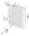
- FIG. 5illustrates an example of a calibration procedure in accordance with an aspect of the invention.
- FIG. 6illustrates an example of a method for calibrating a gesture recognition interface system in accordance with an aspect of the invention.
- the present inventionrelates generally to interface systems, and specifically to calibration of a gesture recognition interface system.
- a useremploys an input object to provide simulated inputs to a computer or other electronic device associated with the visible light images.
- the simulated inputsare provided by gestures using the input object.
- the usercould provide gestures that include motion and/or contact with a background surface using the input object.
- the input objectcould be, for example, the user's hand; a wand, stylus, pointing stick; or a variety of other devices with which the user can gesture.
- the simulated inputscould be, for example, simulated mouse inputs.
- At least one light sourceilluminates the input object and the background surface behind the input object in a first light spectrum to generate a plurality of images of the input object that are captured by at least one camera.
- the first light spectrumcan be non-visible light, such as infrared (IR) light.
- the at least one cameracan include a pair of stereo cameras.
- the plurality of images of the input objectcould be a plurality of matched pairs of images of the input object, such that each image of the matched pair corresponds to the input object from a different perspective at substantially the same time.
- the plurality of imagescan be employed to determine a three-dimensional location of the input object, with changes in the location being employed to determine physical motion of the input object.
- a controllercan be operative to receive the plurality of images to determine the three-dimensional location information associated with the input object.
- the controllercould then translate the simulated inputs into device inputs based on the three-dimensional location information.
- the controllercould interpret gesture inputs based on motion associated with the one or more end-points of the input object and translate the gesture inputs into inputs to a computer or other device.
- the controllercould also compare the motion associated with the input object with a plurality of predefined gestures stored in a memory, such that a match with a given predefined gesture could correspond to a particular device input.
- the gesture recognition systemcan be calibrated prior to operation, such that the gesture recognition system can accurately detect the location of the input object during normal operation.
- the gesture recognition systemcan be calibrated in an automated manner, such that lengthy and specific manual calibration can be avoided.
- the light sourcescan be deactivated, and a second light spectrum can be shined onto the background surface.
- the second light spectrumcan be, for example, visible light, such that visible white light can be shined onto the background surface.
- the at least one cameracan include a filter that not only permits passage of the first light spectrum, but also permits passage of a small amount of visible light. The at least one camera can thus adjust its exposure to increase the amount of white light that is passed.
- a calibration patterncan then be displayed in the visible light spectrum on the background surface.
- the controllercan thus associate the features of the calibration pattern with known physical locations, such as based on parallax separation of the features of the calibration pattern.
- the calibration patterncan include separate calibration patterns, such as to define projection boundaries and to associate physical locations of the features.
- the light sourcescan thus be reactivated and the at least one camera exposure can be readjusted, such that the gesture recognition system can be ready to receive and translate simulated inputs.
- FIG. 1illustrates an example of a gesture recognition interface system 10 in accordance with an aspect of the invention.
- the gesture recognition interface system 10includes a first camera 12 and a second camera 14 . Coupled to each of the first camera 12 and the second camera 14 , respectively, is a first IR light source 16 and a second IR light source 18 .
- the first camera 12 and the second camera 14may each include an IR filter, such that the respective camera may pass IR light and substantially filter other light spectrums.
- the IR filters of the first camera 12 and the second camera 14may also be configured to receive a small amount of the visible light spectrum relative to the IR spectrum during a calibration procedure, as explained below.
- the first IR light source 16 and the second IR light source 18each illuminate a background surface 20 which can be retroreflective.
- IR light from the first IR light source 16can be reflected substantially directly back to the first camera 12 and IR light from the second IR light source 18 can be reflected substantially directly back to the second camera 14 .
- an object that is placed above the background surface 20may reflect a significantly lesser amount of IR light back to each of the first camera 12 and the second camera 14 , respectively. Therefore, such an object can appear to each of the first camera 12 and the second camera 14 as a silhouette image, such that it can appear as a substantially darker object in the foreground of a highly illuminated background surface.
- the background surface 20may not be completely retroreflective, but may include a Lambertian factor to facilitate viewing by users at various angles relative to the background surface 20 .
- An input object 22can provide simulated inputs over the background surface 20 .
- the input object 22is demonstrated as a user's hand, such that the simulated inputs can be provided through hand gestures. It is to be understood that the use of a hand to provide simulated inputs via hand gestures is but one example implementation of the gesture recognition interface system 10 . Examples of other types of input objects could include a stylus, wand, pointing stick, or any of a variety of devices that could provide gestures to simulate inputs. It is to be further understood that the input object 22 can be sensorless, in that it need not be specially designed or suited for use in the gesture recognition interface system 10 .
- a user's naked handcould be used as the input object, and thus a user need not wear a glove that includes retroreflective material or one or more position sensors to provide gesture inputs to the gesture recognition interface system 10 in accordance with an aspect of the invention.
- the first camera 12 and the second camera 14each receive separate silhouette images of the input object 22 , where each of the separate silhouette images received, respectively, by the first camera 12 and the second camera 14 are a matched pair.
- each of the first camera 12 and the second camera 14could rapidly take still photograph images at, for example, sixty times per second, such that each still photograph image taken by the first camera 12 is matched to a still photograph image taken by the second camera 14 at substantially the same time.
- the input objectcan appear to be in a different location relative to the retroreflective screen in each silhouette image matched pair captured by each of the first camera 12 and the second camera 14 , respectively, due to parallax caused by the different mounted locations of each of the first camera 12 and the second camera 14 .
- the first camera 12 and the second camera 14can each provide their respective separate silhouette images of the input object 22 to a controller 24 .
- the controller 24could reside, for example, within a computer (not shown) for which the gesture recognition interface system 10 is designed to provide a gesture recognition interface. It is to be understood, however, that the hosting of a controller is not limited to a standalone computer, but could be included in embedded processors.
- the controller 24can process the respective silhouette images associated with the input object 22 to generate three-dimensional location data associated with the input object 22 .
- each of the first camera 12 and the second camera 14could be mounted at a pre-determined angle relative to the background surface 20 .
- the controller 24could determine the three-dimensional physical location of the input object 22 based on a relative parallax separation of the matched pair of images of the input object 22 at a given time.
- the controller 24could also determine the three-dimensional physical location of at least one end-point, such as a fingertip, associated with the input object 22 .
- the gesture recognition interface system 10can also include a projector 26 configured to project image data.
- the projector 26can provide an output interface, such as, for example, computer monitor data, for which the user can interact and provide inputs using the input object 22 .
- the projector 26can project the image data onto the background surface 20 . Because the IR light sources 16 and 18 do not illuminate visible light, the IR illumination does not interfere with the image data projected from the projector 26 . The user can thus employ the input object 22 directly onto the image data to simulate inputs, such as, for example, mouse inputs.
- the controller 24includes an automated calibration component 28 .
- the automated calibration component 28can be configured, such as in response to a manual input, to begin a calibration procedure, such that the controller 24 can be calibrated to accurately calculate the three-dimensional physical location of the input object 22 .
- the automated calibration component 28can deactivate the first IR light source 16 and the second IR light source 18 .
- the projector 26can project visible white light onto the background surface 20 .
- the first and second camera 12 and 14can include IR filters that can be configured to pass a relatively small amount of visible light.
- FIG. 2illustrates an example of a graph 50 of filter performance of the first camera 12 and the second camera 14 of the gesture recognition interface system 10 in accordance with an aspect of the invention. Specifically, the graph 50 illustrates a plot of wavelength of light in nanometers versus percentage of transmission, such that higher percentages indicate greater amounts of light passed for a given wavelength.
- the graph 50demonstrates that, at higher wavelengths (e.g., beginning at approximately 680 nm), the filter passes a substantial amount of the light. As a result, IR light (e.g., around approximately 850 nm) is substantially completely passed by the filter.
- the filteris also configured to pass a relatively small amount of the visible light spectrum, from approximately 360 nm to approximately 670 nm. In the example of FIG. 2 , the graph 50 demonstrates a small peak at approximately 500 nm. It is to be understood that the graph 50 in the example of FIG. 2 is demonstrated as an ideal plot, such that it demonstrates a very linear performance across the demonstrated ranges of wavelength. As such, the plot of wavelength versus transmission percentage for a given filter to be used with the gesture recognition interface system 10 is likely to include non-linear variations, particularly from one filter to another.
- a filter configured to provide the performance demonstrated by the graph 50can typically be commercially available at a price that can be significantly cheaper than one that is configured to pass substantially nothing but IR light.
- a filtersuch as described by the graph 50 in the example of FIG. 2 , and such that it is capable of implementing a small amount of visible light in the performance of a calibration procedure, as described below, substantial cost-savings can be achieved for the gesture recognition interface system 10 .
- the filteris designed to pass substantially greater IR light than visible light, the illumination of IR light from the IR light sources 16 and 18 onto the retroreflective background surface 20 ensures that very little content of the image data projected from the projector 26 is received by the first and second cameras 12 and 14 .
- the projected image data in the visible spectrumdoes not affect the images of the IR light contrast between the input object 22 and the background surface 20 with respect to gesture recognition.
- the automated calibration component 28can command the first and second cameras 12 and 14 to increase their respective exposure.
- changes in exposurecan include changes in exposure time (i.e., image detection integration time), camera aperture opening, and/or camera amplifier gain.
- the automated calibration component 28then commands the controller 24 to project a calibration pattern onto the background surface 20 in the visible light spectrum.
- the calibration patterncan include defined features in the visible light spectrum, such as lines, dots, squares, and/or any of a variety of features that are non-uniform across the entirety of the projection of the calibration pattern.
- the first and second cameras 12 and 14can capture images of the defined features and the controller 24 can ascertain a reflected light contrast between the features of the calibration pattern and the visible white light.
- the controller 24can thus determine a location of the features of the calibration pattern based on parallax separation, similar to determining the location of the input object 22 . Because the controller 24 identifies that the calibration pattern features are located directly on the background surface 20 , the controller 24 can associate the locations of the features with known physical locations in two-dimensional space. Accordingly, the controller 24 is calibrated, such that it can subsequently extrapolate the location of the input object 22 in three-dimensional space.
- the controller 24can be commanded to provide a first calibration pattern that defines a projection boundary of the projector 26 relative to the background surface 20 .
- a calibration patterncould include horizontal and vertical lines that are projected toward the edge of the projection area of the projector 26 . Therefore, the controller 24 can determine the presence of the lines and thus indicate that the lines are projected onto the background surface 20 , as opposed to the projection being skewed, such as by being projected off one or more edges of the background surface 20 .
- FIG. 3illustrates an example of a calibration pattern 100 for the gesture recognition interface system 10 in accordance with an aspect of the invention.
- the calibration pattern 100includes a non-continuous border 102 that can be located near the edges of the projection area of the projector 26 , and also includes a first gap 104 , a second gap 106 , and a third gap 108 .
- the non-continuous border 102can be projected in any of a variety of colors.
- the non-continuous border 102can be black, such that it contrasts significantly relative to the visible white light of the background surface 20 .
- the non-continuous border 102can be projected in a color that is more easily passed by the filter of the first and second cameras 12 and 14 , such as based on the approximately 500 nm peak (i.e., green) in the example of FIG. 2 .
- the calibration patternis projected onto the background surface 20 in the viewing area of the first and second cameras 12 and 14 by the projector 26 in the visible light spectrum.
- the longer side of the non-continuous border 102 with the first gap 104can be designated a top side, as indicated in the example of FIG. 3 , such that the shorter side of the non-continuous border 102 with no gap is a left side.
- the non-continuous border 102can be used to set a boundary for the projector 26 .
- the controller 24can receive the images of the calibration pattern 100 via the first and second cameras 12 and 14 to attempt to identify the four sides of the non-continuous border 102 . If one of the edges of the border 102 is missing, such as based on being projected off the edge of the background surface, the controller 24 can adjust the projection of the calibration pattern 100 .
- the projection of the calibration pattern 100can be zoomed, shifted, and/or otherwise adjusted until the controller 24 can identify each side of the non-continuous border 102 .
- the projector 26 or the background surface 20can be moved, such as based on servo control, until the controller 24 can identify each side of the non-continuous border 102 .
- the controller 24can change the calibration pattern 100 , such as by shortening a side of the non-continuous border 102 until the controller 24 can identify each side of the non-continuous border 102 .
- the automated calibration component 28 and/or the controller 24can be programmed to recognize the non-continuous border 102 and to identify the orientation of the non-continuous border 102 via the first, second, and third gaps 104 , 106 , and 108 .
- the controller 24can be calibrated to properly identify a two-dimensional X-Y coordinate location on the background surface 20 .
- FIG. 4illustrates another example of a calibration pattern 150 for a gesture recognition interface system in accordance with an aspect of the invention.
- the calibration pattern 150includes a repeated pattern of features that contrast with the background surface 20 , demonstrated in the example of FIG. 4 as a plurality of black dots 152 .
- the black dots 152can be sized to be approximately the size of a fingertip in diameter (e.g., 1 ⁇ 2′′), and can thus be tuned by the automated calibration component 28 to be detected.
- the automated calibration component 28calibrates the controller 24 by detecting the position of the black dots 152 via the first camera 12 relative to the second camera 14 . Specifically, the controller 24 determines a parallax separation between the black dots 152 in the images received from the first camera 12 and the images received from the second camera 14 . By identifying the parallax separation of the black dots 152 relative to a zero-height location of the black dots 152 based on their projection onto the background surface 20 , the controller 24 can thus calculate a calibrated location of the background surface 20 . Therefore, subsequent to calibration, the controller 24 can extrapolate a three-dimensional physical location of the input object 22 in the viewing area of the first camera 12 and the second camera 14 relative to the height of the background surface 20 .
- the calibration pattern 100nor the calibration pattern 150 are intended to be limited by the respective examples of FIGS. 3 and 4 .
- the calibration pattern 100can be continuous, such that orientation is not based on the first, second, and third gaps 104 , 106 , and 108 , or is not necessary.
- the calibration pattern 100can include non-intersecting line segments at each edge, with each line segment being individually and/or sequentially moved from the outer projection edge inward in a frame-by-frame manner until identified by the controller.
- the calibration pattern 150need not be a series of black dots 152 , but could be any of a variety of patterns that has distinct and clearly ascertainable features for identification by the automated calibration component 28 .
- the automated calibration component 28can command the controller 24 to project a single calibration pattern that incorporates the features of the calibration pattern 100 and the calibration pattern 150 .
- the single calibration patterncan be implemented to both define the projection boundaries relative to the background surface and to associate the features with the two-dimensional physical locations.
- the automated calibration component 28can reactivate the first and second IR light sources 16 and 18 .
- the automated calibration component 28can decrease the exposure of the first and second cameras 12 and 14 to the amount at which the first and second cameras 12 and 14 were set prior to the calibration procedure.
- the exposure of the first and second cameras 12 and 14can be set to receive the IR light that is provided by the first and second IR light sources 16 and 18 and reflected from the background surface 20 . Accordingly, the gesture recognition interface system 10 is ready to receive and translate simulated inputs via the input object 22 .
- the gesture recognition interface system 10 in the example of FIG. 1is intended to represent but one example of a gesture recognition interface system in accordance with an aspect of the invention.
- the gesture recognition interface system 10could include more than two cameras that each supply respective silhouette images of the input object 22 to the controller 24 .
- the example of FIG. 1demonstrates that the background surface 20 is mounted on a table 30 . It is to be understood that such an arrangement is demonstrated only for the sake of ergonomic concerns, but that the background surface 20 can be placed in a variety of different arrangements for each of the cameras 12 and 14 to be capable of receiving the respective silhouette images of the input object 22 .
- the table 30could mount the projector 26 underneath, such that the background surface 20 displays rear-projected image data.
- the light sources 16 and 18are not limited to IR light sources, and the projection of the calibration pattern, such as calibration patterns 100 and 150 , is not limited to visible light. Therefore, other light spectrums could be provided from the light sources 16 and 18 , and/or the calibration pattern can be projected in a different, non-visible light spectrum.
- the gesture recognition interface system 10may not include a projector at all.
- the background surface 20could be a liquid crystal display (LCD) screen.
- the image data and the calibration patterncould be displayed on the background surface 20 as an LCD image, and not a projected image.
- gesture inputscan be simulated above it, similar to as described above.
- the silhouette imagescan be based on a light contrast of IR light reflected from the input object relative to a substantially less reflective background surface 20 that is the LCD screen.
- the calibration pattern(s)can still be displayed in the visible light spectrum upon deactivation of the IR light sources, as described above. Accordingly, the gesture recognition interface system 10 can be configured in any of a variety of ways.
- FIG. 5illustrates an example of a calibration procedure 200 in accordance with an aspect of the invention.
- the calibration procedure 200can be implemented in the gesture recognition interface system 10 in the example of FIG. 1 .
- the calibration procedure 200demonstrates an overhead view of the projector 26 projecting a predefined calibration pattern 202 onto the background surface 20 .
- the projection of the predefined calibration pattern 202can be performed during a calibration procedure, such as in response to a manual input.
- the predefined calibration pattern 202can be projected in the visible light spectrum to users of the gesture recognition interface system 10 as it is being projected onto the background surface 20 after deactivation of the IR light sources 16 and 18 .
- FIG. 5it is to be assumed that the projection boundaries of the projector 26 relative to the background surface 20 have already been defined.
- the predefined calibration pattern 202is demonstrated as a plurality of equally spaced dots 204 . It is to be understood, however, that the predefined calibration pattern 202 is not limited to the dots 204 demonstrated in the example of FIG. 5 , but that any distinct and identifiable pattern may be implemented in the calibration procedure 200 .
- the first and second cameras 12 and 14can each capture images of the projected predefined calibration pattern and provide the images to the controller 24 (not shown in the example of FIG. 5 ).
- the physical location of each of the dots 204 of the predefined calibration patterncan thus be specifically identified by the controller 24 .
- the controller 24can identify the location of each of the dots 204 based on a parallax separation of the dots 204 in the images received from the camera 12 relative to the dots 204 in the images received from the camera 14 .
- the controller 24can thus correlate the location of the features of the predefined calibration pattern 202 appearing in the images of the cameras 12 and 14 with the precise physical locations on the background surface 20 . As a result, the controller 24 can extrapolate three-dimensional locations of the input object 22 based on the calibration information that is calculated based on the physical locations of the dots 204 on the background surface 20 . Accordingly, calibration of the gesture recognition interface system 10 is achieved.
- FIG. 6a methodology in accordance with various aspects of the present invention will be better appreciated with reference to FIG. 6 . While, for purposes of simplicity of explanation, the methodologies of FIG. 6 are shown and described as executing serially, it is to be understood and appreciated that the present invention is not limited by the illustrated order, as some aspects could, in accordance with the present invention, occur in different orders and/or concurrently with other aspects from that shown and described herein. Moreover, not all illustrated features may be required to implement a methodology in accordance with an aspect of the present invention.
- FIG. 6illustrates an example of a method 250 for calibrating a gesture recognition interface system in accordance with an aspect of the invention.
- at least one light sourceis confirmed to be deactivated, the light source providing illumination onto a background surface in a first light spectrum.
- the illuminationcan be provided onto the background surface to generate a reflected light contrast between an input object and the illuminated background surface.
- the first light spectrumcan be IR light, and the background surface could be retroreflective.
- the background surfacecould also be an output display, such that it displays image data such as computer monitor data.
- an exposureis adjusted for at least one camera that is filtered to pass the first light spectrum and substantially less of a second light spectrum. The adjustment can be to increase the exposure.
- the at least one cameracan be configured to provide a plurality of images of the reflected light contrast between the input object and the illuminated background surface to a gesture recognition controller.
- the at least one cameracan be collocated with the respective at least one light source, such that the retroreflectivity of the background surface provides more light to be reflected to the respective camera.
- At 256at least one calibration pattern is projected onto the background surface in the second light spectrum.
- the second light spectrumcan be visible light.
- features of the at least one calibration patternare associated with known physical locations.
- the at least one calibration patterncan include a first calibration pattern with features that define the projection boundaries of a projector that projects the calibration pattern relative to the background surface.
- the at least one calibration patterncan also include a second calibration pattern with features that are associated with the known physical locations in two-dimensional space on the background surface. The association can occur based on a parallax separation of the features in images received at each of multiple stereo cameras.
- the at least one light sourcecan be reactivated to resume providing illumination in the first light spectrum.
- the exposure of the at least one camerais readjusted to its pre-calibration setting. The readjustment can be to decrease the exposure.
- the camerasBased on the intensity of the at least one light source and the passing of substantially more of the first light spectrum, the cameras can receive clear images that are substantially unaffected by image data that is projected in the second light spectrum. As a result, images of a reflected light contrast between an input object and the background surface can be provided to the gesture recognition controller. Based on the calibration procedure, a parallax separation of the images can be used to extrapolate a three-dimensional physical location of the input object. Therefore, gesture inputs can be simulated and translated into device inputs.
Landscapes
- Engineering & Computer Science (AREA)
- General Engineering & Computer Science (AREA)
- Theoretical Computer Science (AREA)
- Human Computer Interaction (AREA)
- Physics & Mathematics (AREA)
- General Physics & Mathematics (AREA)
- Multimedia (AREA)
- User Interface Of Digital Computer (AREA)
Abstract
Description
Claims (17)
Priority Applications (2)
| Application Number | Priority Date | Filing Date | Title |
|---|---|---|---|
| US11/933,814US8139110B2 (en) | 2007-11-01 | 2007-11-01 | Calibration of a gesture recognition interface system |
| EP08014912AEP2068230B1 (en) | 2007-11-01 | 2008-08-22 | Calibration of a gesture recognition interface system |
Applications Claiming Priority (1)
| Application Number | Priority Date | Filing Date | Title |
|---|---|---|---|
| US11/933,814US8139110B2 (en) | 2007-11-01 | 2007-11-01 | Calibration of a gesture recognition interface system |
Publications (2)
| Publication Number | Publication Date |
|---|---|
| US20090116742A1 US20090116742A1 (en) | 2009-05-07 |
| US8139110B2true US8139110B2 (en) | 2012-03-20 |
Family
ID=40568328
Family Applications (1)
| Application Number | Title | Priority Date | Filing Date |
|---|---|---|---|
| US11/933,814Active2031-01-18US8139110B2 (en) | 2007-11-01 | 2007-11-01 | Calibration of a gesture recognition interface system |
Country Status (2)
| Country | Link |
|---|---|
| US (1) | US8139110B2 (en) |
| EP (1) | EP2068230B1 (en) |
Cited By (9)
| Publication number | Priority date | Publication date | Assignee | Title |
|---|---|---|---|---|
| US20100277411A1 (en)* | 2009-05-01 | 2010-11-04 | Microsoft Corporation | User tracking feedback |
| US20110156999A1 (en)* | 2009-12-30 | 2011-06-30 | Industrial Technology Research Institute | Gesture recognition methods and systems |
| US20110296352A1 (en)* | 2010-05-27 | 2011-12-01 | Microsoft Corporation | Active calibration of a natural user interface |
| US20130033571A1 (en)* | 2011-08-03 | 2013-02-07 | General Electric Company | Method and system for cropping a 3-dimensional medical dataset |
| US9613328B2 (en) | 2012-12-21 | 2017-04-04 | Industrial Technology Research Institute | Workflow monitoring and analysis system and method thereof |
| US9653044B2 (en) | 2014-02-14 | 2017-05-16 | Microsoft Technology Licensing, Llc | Interactive display system |
| US9720506B2 (en) | 2014-01-14 | 2017-08-01 | Microsoft Technology Licensing, Llc | 3D silhouette sensing system |
| DE102016003021A1 (en)* | 2016-03-12 | 2017-09-14 | Audi Ag | Motor vehicle control device and method for determining a position of an installed in a motor vehicle optical sensor |
| US20190050619A1 (en)* | 2017-08-09 | 2019-02-14 | Synaptics Incorporated | Providing test patterns for sensor calibration |
Families Citing this family (75)
| Publication number | Priority date | Publication date | Assignee | Title |
|---|---|---|---|---|
| US8180114B2 (en)* | 2006-07-13 | 2012-05-15 | Northrop Grumman Systems Corporation | Gesture recognition interface system with vertical display |
| US8589824B2 (en) | 2006-07-13 | 2013-11-19 | Northrop Grumman Systems Corporation | Gesture recognition interface system |
| US8972902B2 (en)* | 2008-08-22 | 2015-03-03 | Northrop Grumman Systems Corporation | Compound gesture recognition |
| US9696808B2 (en)* | 2006-07-13 | 2017-07-04 | Northrop Grumman Systems Corporation | Hand-gesture recognition method |
| US8234578B2 (en)* | 2006-07-25 | 2012-07-31 | Northrop Grumman Systems Corporatiom | Networked gesture collaboration system |
| US8432448B2 (en) | 2006-08-10 | 2013-04-30 | Northrop Grumman Systems Corporation | Stereo camera intrusion detection system |
| US8139110B2 (en) | 2007-11-01 | 2012-03-20 | Northrop Grumman Systems Corporation | Calibration of a gesture recognition interface system |
| US9377874B2 (en)* | 2007-11-02 | 2016-06-28 | Northrop Grumman Systems Corporation | Gesture recognition light and video image projector |
| KR20090063679A (en)* | 2007-12-14 | 2009-06-18 | 삼성전자주식회사 | Image display device with pointing function and method |
| US9367166B1 (en)* | 2007-12-21 | 2016-06-14 | Cypress Semiconductor Corporation | System and method of visualizing capacitance sensing system operation |
| US20100066983A1 (en)* | 2008-06-17 | 2010-03-18 | Jun Edward K Y | Methods and systems related to a projection surface |
| US8345920B2 (en)* | 2008-06-20 | 2013-01-01 | Northrop Grumman Systems Corporation | Gesture recognition interface system with a light-diffusive screen |
| US9417700B2 (en) | 2009-05-21 | 2016-08-16 | Edge3 Technologies | Gesture recognition systems and related methods |
| US8054290B2 (en)* | 2009-05-27 | 2011-11-08 | Microsoft Corporation | Image contrast enhancement in depth sensor |
| WO2011009108A2 (en)* | 2009-07-17 | 2011-01-20 | Universal Robotics, Inc. | System and method for automatic calibration of stereo images |
| US9274699B2 (en)* | 2009-09-03 | 2016-03-01 | Obscura Digital | User interface for a large scale multi-user, multi-touch system |
| US20110050640A1 (en)* | 2009-09-03 | 2011-03-03 | Niklas Lundback | Calibration for a Large Scale Multi-User, Multi-Touch System |
| US20110055703A1 (en)* | 2009-09-03 | 2011-03-03 | Niklas Lundback | Spatial Apportioning of Audio in a Large Scale Multi-User, Multi-Touch System |
| US8730183B2 (en)* | 2009-09-03 | 2014-05-20 | Obscura Digital | Large scale multi-user, multi-touch system |
| US8907894B2 (en)* | 2009-10-20 | 2014-12-09 | Northridge Associates Llc | Touchless pointing device |
| US8396252B2 (en) | 2010-05-20 | 2013-03-12 | Edge 3 Technologies | Systems and related methods for three dimensional gesture recognition in vehicles |
| US20120032946A1 (en)* | 2010-08-04 | 2012-02-09 | Wei-Chung Wang | New calibration procedures for three-dimensional digital image correlation |
| US8655093B2 (en) | 2010-09-02 | 2014-02-18 | Edge 3 Technologies, Inc. | Method and apparatus for performing segmentation of an image |
| US8467599B2 (en) | 2010-09-02 | 2013-06-18 | Edge 3 Technologies, Inc. | Method and apparatus for confusion learning |
| US8582866B2 (en) | 2011-02-10 | 2013-11-12 | Edge 3 Technologies, Inc. | Method and apparatus for disparity computation in stereo images |
| US8666144B2 (en) | 2010-09-02 | 2014-03-04 | Edge 3 Technologies, Inc. | Method and apparatus for determining disparity of texture |
| US8682030B2 (en) | 2010-09-24 | 2014-03-25 | Microsoft Corporation | Interactive display |
| US9477302B2 (en) | 2012-08-10 | 2016-10-25 | Google Inc. | System and method for programing devices within world space volumes |
| US20150153715A1 (en)* | 2010-09-29 | 2015-06-04 | Google Inc. | Rapidly programmable locations in space |
| US8970589B2 (en) | 2011-02-10 | 2015-03-03 | Edge 3 Technologies, Inc. | Near-touch interaction with a stereo camera grid structured tessellations |
| KR101423536B1 (en)* | 2011-06-14 | 2014-08-01 | 한국전자통신연구원 | System for constructiing mixed reality using print medium and method therefor |
| US9207767B2 (en)* | 2011-06-29 | 2015-12-08 | International Business Machines Corporation | Guide mode for gesture spaces |
| EP2924548B1 (en)* | 2011-07-18 | 2020-01-01 | MultiTaction Oy | Correction of touch screen camera geometry |
| US8896688B2 (en)* | 2011-11-04 | 2014-11-25 | Hewlett-Packard Development Company, L.P. | Determining position in a projection capture system |
| US9672609B1 (en) | 2011-11-11 | 2017-06-06 | Edge 3 Technologies, Inc. | Method and apparatus for improved depth-map estimation |
| US9070019B2 (en) | 2012-01-17 | 2015-06-30 | Leap Motion, Inc. | Systems and methods for capturing motion in three-dimensional space |
| US10691219B2 (en) | 2012-01-17 | 2020-06-23 | Ultrahaptics IP Two Limited | Systems and methods for machine control |
| US12260023B2 (en) | 2012-01-17 | 2025-03-25 | Ultrahaptics IP Two Limited | Systems and methods for machine control |
| US8638989B2 (en) | 2012-01-17 | 2014-01-28 | Leap Motion, Inc. | Systems and methods for capturing motion in three-dimensional space |
| US9501152B2 (en) | 2013-01-15 | 2016-11-22 | Leap Motion, Inc. | Free-space user interface and control using virtual constructs |
| US11493998B2 (en) | 2012-01-17 | 2022-11-08 | Ultrahaptics IP Two Limited | Systems and methods for machine control |
| US8693731B2 (en) | 2012-01-17 | 2014-04-08 | Leap Motion, Inc. | Enhanced contrast for object detection and characterization by optical imaging |
| US20150253428A1 (en) | 2013-03-15 | 2015-09-10 | Leap Motion, Inc. | Determining positional information for an object in space |
| US9679215B2 (en) | 2012-01-17 | 2017-06-13 | Leap Motion, Inc. | Systems and methods for machine control |
| GB2499979A (en)* | 2012-01-20 | 2013-09-11 | Light Blue Optics Ltd | Touch-sensitive image display devices |
| US20140362052A1 (en)* | 2012-01-20 | 2014-12-11 | Light Blue Optics Ltd | Touch Sensitive Image Display Devices |
| US9134814B2 (en)* | 2012-04-05 | 2015-09-15 | Seiko Epson Corporation | Input device, display system and input method |
| US9747306B2 (en)* | 2012-05-25 | 2017-08-29 | Atheer, Inc. | Method and apparatus for identifying input features for later recognition |
| US9285893B2 (en) | 2012-11-08 | 2016-03-15 | Leap Motion, Inc. | Object detection and tracking with variable-field illumination devices |
| US10609285B2 (en) | 2013-01-07 | 2020-03-31 | Ultrahaptics IP Two Limited | Power consumption in motion-capture systems |
| US9465461B2 (en) | 2013-01-08 | 2016-10-11 | Leap Motion, Inc. | Object detection and tracking with audio and optical signals |
| US9459697B2 (en) | 2013-01-15 | 2016-10-04 | Leap Motion, Inc. | Dynamic, free-space user interactions for machine control |
| JP6111706B2 (en)* | 2013-02-01 | 2017-04-12 | セイコーエプソン株式会社 | Position detection apparatus, adjustment method, and adjustment program |
| US9372541B2 (en) | 2013-03-11 | 2016-06-21 | Honeywell International Inc. | Gesture recognition system operability verification |
| US10721448B2 (en) | 2013-03-15 | 2020-07-21 | Edge 3 Technologies, Inc. | Method and apparatus for adaptive exposure bracketing, segmentation and scene organization |
| JP6044426B2 (en)* | 2013-04-02 | 2016-12-14 | 富士通株式会社 | Information operation display system, display program, and display method |
| US9411432B2 (en)* | 2013-04-18 | 2016-08-09 | Fuji Xerox Co., Ltd. | Systems and methods for enabling gesture control based on detection of occlusion patterns |
| US9916009B2 (en) | 2013-04-26 | 2018-03-13 | Leap Motion, Inc. | Non-tactile interface systems and methods |
| JP2014220720A (en)* | 2013-05-09 | 2014-11-20 | 株式会社東芝 | Electronic apparatus, information processing method, and program |
| US9609262B2 (en)* | 2013-06-27 | 2017-03-28 | Intel Corporation | Device for adaptive projection |
| US10281987B1 (en) | 2013-08-09 | 2019-05-07 | Leap Motion, Inc. | Systems and methods of free-space gestural interaction |
| US10846942B1 (en) | 2013-08-29 | 2020-11-24 | Ultrahaptics IP Two Limited | Predictive information for free space gesture control and communication |
| US9632572B2 (en) | 2013-10-03 | 2017-04-25 | Leap Motion, Inc. | Enhanced field of view to augment three-dimensional (3D) sensory space for free-space gesture interpretation |
| US9996638B1 (en) | 2013-10-31 | 2018-06-12 | Leap Motion, Inc. | Predictive information for free space gesture control and communication |
| GB2523077A (en)* | 2013-12-23 | 2015-08-19 | Light Blue Optics Ltd | Touch sensing systems |
| US9613262B2 (en) | 2014-01-15 | 2017-04-04 | Leap Motion, Inc. | Object detection and tracking for providing a virtual device experience |
| JP6349838B2 (en)* | 2014-01-21 | 2018-07-04 | セイコーエプソン株式会社 | POSITION DETECTION DEVICE, POSITION DETECTION SYSTEM, AND POSITION DETECTION DEVICE CONTROL METHOD |
| JP6394190B2 (en)* | 2014-03-18 | 2018-09-26 | 富士ゼロックス株式会社 | System and method enabling gesture control based on occlusion pattern detection |
| US9785247B1 (en) | 2014-05-14 | 2017-10-10 | Leap Motion, Inc. | Systems and methods of tracking moving hands and recognizing gestural interactions |
| US9741169B1 (en) | 2014-05-20 | 2017-08-22 | Leap Motion, Inc. | Wearable augmented reality devices with object detection and tracking |
| CN204480228U (en) | 2014-08-08 | 2015-07-15 | 厉动公司 | motion sensing and imaging device |
| DE102014113389A1 (en)* | 2014-09-17 | 2016-03-17 | Pilz Gmbh & Co. Kg | Method and device for identifying structural elements of a projected structural pattern in camera images |
| US10656720B1 (en) | 2015-01-16 | 2020-05-19 | Ultrahaptics IP Two Limited | Mode switching for integrated gestural interaction and multi-user collaboration in immersive virtual reality environments |
| TWI653563B (en)* | 2016-05-24 | 2019-03-11 | 仁寶電腦工業股份有限公司 | Projection touch image selection method |
| US11698457B2 (en)* | 2019-09-04 | 2023-07-11 | Pixart Imaging Inc. | Object detecting system and object detecting method |
Citations (97)
| Publication number | Priority date | Publication date | Assignee | Title |
|---|---|---|---|---|
| US4468694A (en) | 1980-12-30 | 1984-08-28 | International Business Machines Corporation | Apparatus and method for remote displaying and sensing of information using shadow parallax |
| JPS62264390A (en) | 1986-05-12 | 1987-11-17 | Omron Tateisi Electronics Co | Visual sense recognizing device for supervisory robot |
| US4843568A (en) | 1986-04-11 | 1989-06-27 | Krueger Myron W | Real time perception of and response to the actions of an unencumbered participant/user |
| US4924506A (en) | 1986-07-22 | 1990-05-08 | Schlumberger Systems & Services, Inc. | Method for directly measuring area and volume using binocular stereo vision |
| JPH0431996A (en) | 1990-05-28 | 1992-02-04 | Matsushita Electric Works Ltd | Image recognition type burgler sensor |
| JPH04271423A (en) | 1991-02-27 | 1992-09-28 | Nippon Telegr & Teleph Corp <Ntt> | Information input method |
| US5220441A (en) | 1990-09-28 | 1993-06-15 | Eastman Kodak Company | Mechanism for determining parallax between digital images |
| US5239373A (en) | 1990-12-26 | 1993-08-24 | Xerox Corporation | Video computational shared drawing space |
| EP0571702A2 (en) | 1992-05-26 | 1993-12-01 | Takenaka Corporation | Hand pointing type input unit and wall computer module |
| US5475422A (en) | 1993-06-21 | 1995-12-12 | Nippon Telegraph And Telephone Corporation | Method and apparatus for reconstructing three-dimensional objects |
| US5483261A (en) | 1992-02-14 | 1996-01-09 | Itu Research, Inc. | Graphical input controller and method with rear screen image detection |
| US5563988A (en) | 1994-08-01 | 1996-10-08 | Massachusetts Institute Of Technology | Method and system for facilitating wireless, full-body, real-time user interaction with a digitally represented visual environment |
| WO1998013746A1 (en) | 1996-09-27 | 1998-04-02 | Samsung Electronics Co. Ltd. | Method for feeding information into a computer |
| DE19739285C1 (en) | 1997-09-08 | 1998-11-19 | Siemens Nixdorf Inf Syst | Data representation and virtual input device |
| EP0913790A1 (en) | 1997-10-29 | 1999-05-06 | Takenaka Corporation | Hand pointing apparatus |
| US5913727A (en) | 1995-06-02 | 1999-06-22 | Ahdoot; Ned | Interactive movement and contact simulation game |
| US5999185A (en) | 1992-03-30 | 1999-12-07 | Kabushiki Kaisha Toshiba | Virtual reality control using image, model and control data to manipulate interactions |
| US6002808A (en) | 1996-07-26 | 1999-12-14 | Mitsubishi Electric Information Technology Center America, Inc. | Hand gesture control system |
| WO2000002187A1 (en) | 1998-07-01 | 2000-01-13 | Deluca Michael J | Stereoscopic user interface method and apparatus |
| WO2000021023A1 (en) | 1998-10-07 | 2000-04-13 | Intel Corporation | Controlling a pointer using digital video |
| WO2000055802A1 (en) | 1999-03-17 | 2000-09-21 | Siemens Aktiengesellschaft | Interaction device |
| US6147678A (en) | 1998-12-09 | 2000-11-14 | Lucent Technologies Inc. | Video hand image-three-dimensional computer interface with multiple degrees of freedom |
| US6195104B1 (en) | 1997-12-23 | 2001-02-27 | Philips Electronics North America Corp. | System and method for permitting three-dimensional navigation through a virtual reality environment using camera-based gesture inputs |
| US6204852B1 (en) | 1998-12-09 | 2001-03-20 | Lucent Technologies Inc. | Video hand image three-dimensional computer interface |
| US6222465B1 (en) | 1998-12-09 | 2001-04-24 | Lucent Technologies Inc. | Gesture-based computer interface |
| US20010006426A1 (en) | 1996-07-18 | 2001-07-05 | Korea Institute Of Science And Technology | Holographic projection screen for displaying a three-dimensional color images and optical display system using the holographic screen |
| US20010043719A1 (en) | 1997-03-21 | 2001-11-22 | Kenichi Harakawa | Hand pointing device |
| US6327381B1 (en) | 1994-12-29 | 2001-12-04 | Worldscape, Llc | Image transformation and synthesis methods |
| US6353428B1 (en) | 1997-02-28 | 2002-03-05 | Siemens Aktiengesellschaft | Method and device for detecting an object in an area radiated by waves in the invisible spectral range |
| US6359612B1 (en) | 1998-09-30 | 2002-03-19 | Siemens Aktiengesellschaft | Imaging system for displaying image information that has been acquired by means of a medical diagnostic imaging device |
| US20020090146A1 (en) | 2001-01-09 | 2002-07-11 | Siemens Aktiengesellschaft | Hand recognition with position determination |
| EP1223537A2 (en) | 2001-01-09 | 2002-07-17 | Siemens Aktiengesellschaft | Controllable device with user authentication |
| US20020093666A1 (en)* | 2001-01-17 | 2002-07-18 | Jonathan Foote | System and method for determining the location of a target in a room or small area |
| US20020122113A1 (en) | 1999-08-09 | 2002-09-05 | Foote Jonathan T. | Method and system for compensating for parallax in multiple camera systems |
| US20020126161A1 (en) | 1994-07-05 | 2002-09-12 | Hitachi, Ltd. | Information processing system |
| US20020186221A1 (en) | 2001-06-05 | 2002-12-12 | Reactrix Systems, Inc. | Interactive video display system |
| US6512507B1 (en) | 1998-03-31 | 2003-01-28 | Seiko Epson Corporation | Pointing position detection device, presentation system, and method, and computer-readable medium |
| WO2003026299A1 (en) | 2001-09-14 | 2003-03-27 | Accenture Global Services Gmbh | Lab window collaboration |
| US20030058341A1 (en) | 2001-09-27 | 2003-03-27 | Koninklijke Philips Electronics N.V. | Video based detection of fall-down and other events |
| US20030067537A1 (en) | 2001-10-04 | 2003-04-10 | Myers Kenneth J. | System and method for three-dimensional data acquisition |
| US20030085866A1 (en) | 2000-06-06 | 2003-05-08 | Oliver Bimber | Extended virtual table: an optical extension for table-like projection systems |
| US20030156756A1 (en) | 2002-02-15 | 2003-08-21 | Gokturk Salih Burak | Gesture recognition system using depth perceptive sensors |
| US20030218761A1 (en) | 2002-05-22 | 2003-11-27 | Carlo Tomasi | Method and apparatus for approximating depth of an object's placement onto a monitored region with applications to virtual interface devices |
| US6681031B2 (en) | 1998-08-10 | 2004-01-20 | Cybernet Systems Corporation | Gesture-controlled interfaces for self-service machines and other applications |
| US6695770B1 (en) | 1999-04-01 | 2004-02-24 | Dominic Kin Leung Choy | Simulated human interaction systems |
| US20040046747A1 (en) | 2000-09-26 | 2004-03-11 | Eugenio Bustamante | Providing input signals |
| US6714901B1 (en) | 1997-11-19 | 2004-03-30 | Inria Institut National De Recherche En Informatique Et En Automatique | Electronic device for processing image-data, for simulating the behaviour of a deformable object |
| US6720949B1 (en) | 1997-08-22 | 2004-04-13 | Timothy R. Pryor | Man machine interfaces and applications |
| US20040108990A1 (en) | 2001-01-08 | 2004-06-10 | Klony Lieberman | Data input device |
| US20040113885A1 (en) | 2001-05-31 | 2004-06-17 | Yakup Genc | New input devices for augmented reality applications |
| US20040125207A1 (en) | 2002-08-01 | 2004-07-01 | Anurag Mittal | Robust stereo-driven video-based surveillance |
| US6788809B1 (en) | 2000-06-30 | 2004-09-07 | Intel Corporation | System and method for gesture recognition in three dimensions using stereo imaging and color vision |
| US20040183775A1 (en) | 2002-12-13 | 2004-09-23 | Reactrix Systems | Interactive directed light/sound system |
| US6796656B1 (en) | 2003-06-14 | 2004-09-28 | Imatte, Inc. | Generating a matte signal from a retro reflective component of a front projection screen |
| US20040193413A1 (en) | 2003-03-25 | 2004-09-30 | Wilson Andrew D. | Architecture for controlling a computer using hand gestures |
| US6806849B2 (en) | 1998-04-20 | 2004-10-19 | Lightspace Technologies Ab | Multi-planar volumetric display system and method of operation using multi-planar interlacing |
| US20040239761A1 (en) | 2003-05-26 | 2004-12-02 | S1 Corporation | Method of intruder detection and device thereof |
| US20050002074A1 (en) | 2003-07-03 | 2005-01-06 | Holotouch, Inc. | Holographic human-machine interfaces |
| US20050012817A1 (en) | 2003-07-15 | 2005-01-20 | International Business Machines Corporation | Selective surveillance system with active sensor management policies |
| US6857746B2 (en) | 2002-07-01 | 2005-02-22 | Io2 Technology, Llc | Method and system for free-space imaging display and interface |
| US20050052714A1 (en) | 2003-07-24 | 2005-03-10 | Zebra Imaging, Inc. | Enhanced environment visualization using holographic stereograms |
| US20050068537A1 (en) | 2002-07-17 | 2005-03-31 | New York University | Method and apparatus for determining a bidirectional reflectance distribution function of a subject |
| US20050088714A1 (en) | 1997-07-08 | 2005-04-28 | Kremen Stanley H. | Method for creating a holographic screen that reconstructs uniformly magnified three-dimensional images from projected integral photographs |
| US20050110964A1 (en) | 2002-05-28 | 2005-05-26 | Matthew Bell | Interactive video window display system |
| US20050151850A1 (en) | 2004-01-14 | 2005-07-14 | Korea Institute Of Science And Technology | Interactive presentation system |
| US20050166163A1 (en) | 2004-01-23 | 2005-07-28 | Chang Nelson L.A. | Systems and methods of interfacing with a machine |
| US6950534B2 (en) | 1998-08-10 | 2005-09-27 | Cybernet Systems Corporation | Gesture-controlled interfaces for self-service machines and other applications |
| US6956573B1 (en) | 1996-11-15 | 2005-10-18 | Sarnoff Corporation | Method and apparatus for efficiently representing storing and accessing video information |
| US20050275628A1 (en) | 2002-01-25 | 2005-12-15 | Alias Systems Corp. | System for physical rotation of volumetric display enclosures to facilitate viewing |
| US20050285945A1 (en) | 2004-06-25 | 2005-12-29 | Hitachi, Ltd. | Imaging apparatus |
| US20050286101A1 (en) | 2004-04-13 | 2005-12-29 | Board Of Regents, The University Of Texas System | Holographic projector |
| US6983065B1 (en) | 2001-12-28 | 2006-01-03 | Cognex Technology And Investment Corporation | Method for extracting features from an image using oriented filters |
| US20060010400A1 (en)* | 2004-06-28 | 2006-01-12 | Microsoft Corporation | Recognizing gestures and using gestures for interacting with software applications |
| US20060036944A1 (en) | 2004-08-10 | 2006-02-16 | Microsoft Corporation | Surface UI for gesture-based interaction |
| US20060052953A1 (en) | 2003-01-02 | 2006-03-09 | Sociedad Espanola De Carburos Metalicos, S.A. | Analyzing system for the detection of reducing and oxidizing gases in a carrier gas with a metal-oxide-semiconductor sensor arrangement |
| US20060092178A1 (en) | 2004-10-29 | 2006-05-04 | Tanguay Donald O Jr | Method and system for communicating through shared media |
| US20060125799A1 (en) | 2004-08-06 | 2006-06-15 | Hillis W D | Touch driven method and apparatus to integrate and display multiple image layers forming alternate depictions of same subject matter |
| EP1689172A1 (en) | 2001-06-05 | 2006-08-09 | Reactrix Systems, Inc. | Interactive video display system |
| US20060187196A1 (en) | 2005-02-08 | 2006-08-24 | Underkoffler John S | System and method for gesture based control system |
| US20060203363A1 (en) | 2003-08-08 | 2006-09-14 | Patrick Levy-Rosenthal | Three-dimensional image display system |
| US20060209021A1 (en) | 2005-03-19 | 2006-09-21 | Jang Hee Yoo | Virtual mouse driving apparatus and method using two-handed gestures |
| US20070024590A1 (en) | 2004-02-18 | 2007-02-01 | Krepec Rafal J | Camera assisted pen tablet |
| US20070064092A1 (en) | 2005-09-09 | 2007-03-22 | Sandbeg Roy B | Mobile video teleconferencing system and control method |
| WO2008001202A2 (en) | 2006-06-28 | 2008-01-03 | Nokia Corporation | Touchless gesture based input |
| EP1879129A1 (en) | 2006-07-13 | 2008-01-16 | Northrop Grumman Corporation | Gesture recognition simultation system and method |
| EP1879130A2 (en) | 2006-07-13 | 2008-01-16 | Northrop Grumman Corporation | Gesture recognition interface system |
| US20080028325A1 (en) | 2006-07-25 | 2008-01-31 | Northrop Grumman Corporation | Networked gesture collaboration system |
| US20080043106A1 (en) | 2006-08-10 | 2008-02-21 | Northrop Grumman Corporation | Stereo camera intrusion detection system |
| US20080150913A1 (en)* | 2002-05-28 | 2008-06-26 | Matthew Bell | Computer vision based touch screen |
| US20080244468A1 (en) | 2006-07-13 | 2008-10-02 | Nishihara H Keith | Gesture Recognition Interface System with Vertical Display |
| US20090015791A1 (en)* | 2007-07-12 | 2009-01-15 | Nelson Liang An Chang | System and method for generating correspondence mappings using infrared patterns |
| US20090103780A1 (en) | 2006-07-13 | 2009-04-23 | Nishihara H Keith | Hand-Gesture Recognition Method |
| EP2056185A2 (en) | 2007-11-02 | 2009-05-06 | Northrop Grumman Space & Mission Systems Corporation | Gesture recognition light and video image projector |
| US20090135162A1 (en)* | 2005-03-10 | 2009-05-28 | Koninklijke Philips Electronics, N.V. | System and Method For Detecting the Location, Size and Shape of Multiple Objects That Interact With a Touch Screen Display |
| EP2068230A2 (en) | 2007-11-01 | 2009-06-10 | Northrop Grumman Space & Mission Systems Corp. | Calibration of a gesture recognition interface system |
| GB2460937A (en) | 2008-06-20 | 2009-12-23 | Northrop Grumman Corp | A gesture recognition system |
| US20100050133A1 (en) | 2008-08-22 | 2010-02-25 | Nishihara H Keith | Compound Gesture Recognition |
Family Cites Families (2)
| Publication number | Priority date | Publication date | Assignee | Title |
|---|---|---|---|---|
| JP3640156B2 (en)* | 2000-02-22 | 2005-04-20 | セイコーエプソン株式会社 | Pointed position detection system and method, presentation system, and information storage medium |
| WO2003091987A1 (en)* | 2002-04-26 | 2003-11-06 | Idemitsu Kosan Co., Ltd. | Sound absorbing body, sound absorbing structural body, and method of manufacturing these bodies |
- 2007
- 2007-11-01USUS11/933,814patent/US8139110B2/enactiveActive
- 2008
- 2008-08-22EPEP08014912Apatent/EP2068230B1/ennot_activeNot-in-force
Patent Citations (104)
| Publication number | Priority date | Publication date | Assignee | Title |
|---|---|---|---|---|
| US4468694A (en) | 1980-12-30 | 1984-08-28 | International Business Machines Corporation | Apparatus and method for remote displaying and sensing of information using shadow parallax |
| US4843568A (en) | 1986-04-11 | 1989-06-27 | Krueger Myron W | Real time perception of and response to the actions of an unencumbered participant/user |
| JPS62264390A (en) | 1986-05-12 | 1987-11-17 | Omron Tateisi Electronics Co | Visual sense recognizing device for supervisory robot |
| US4924506A (en) | 1986-07-22 | 1990-05-08 | Schlumberger Systems & Services, Inc. | Method for directly measuring area and volume using binocular stereo vision |
| JPH0431996A (en) | 1990-05-28 | 1992-02-04 | Matsushita Electric Works Ltd | Image recognition type burgler sensor |
| US5220441A (en) | 1990-09-28 | 1993-06-15 | Eastman Kodak Company | Mechanism for determining parallax between digital images |
| US5239373A (en) | 1990-12-26 | 1993-08-24 | Xerox Corporation | Video computational shared drawing space |
| JPH04271423A (en) | 1991-02-27 | 1992-09-28 | Nippon Telegr & Teleph Corp <Ntt> | Information input method |
| US5483261A (en) | 1992-02-14 | 1996-01-09 | Itu Research, Inc. | Graphical input controller and method with rear screen image detection |
| US5999185A (en) | 1992-03-30 | 1999-12-07 | Kabushiki Kaisha Toshiba | Virtual reality control using image, model and control data to manipulate interactions |
| EP0571702A2 (en) | 1992-05-26 | 1993-12-01 | Takenaka Corporation | Hand pointing type input unit and wall computer module |
| EP0571702A3 (en) | 1992-05-26 | 1994-10-12 | Takenaka Corp | Hand pointing type input unit and wall computer module. |
| US5475422A (en) | 1993-06-21 | 1995-12-12 | Nippon Telegraph And Telephone Corporation | Method and apparatus for reconstructing three-dimensional objects |
| US20020126161A1 (en) | 1994-07-05 | 2002-09-12 | Hitachi, Ltd. | Information processing system |
| US5563988A (en) | 1994-08-01 | 1996-10-08 | Massachusetts Institute Of Technology | Method and system for facilitating wireless, full-body, real-time user interaction with a digitally represented visual environment |
| US6327381B1 (en) | 1994-12-29 | 2001-12-04 | Worldscape, Llc | Image transformation and synthesis methods |
| US5913727A (en) | 1995-06-02 | 1999-06-22 | Ahdoot; Ned | Interactive movement and contact simulation game |
| US20010006426A1 (en) | 1996-07-18 | 2001-07-05 | Korea Institute Of Science And Technology | Holographic projection screen for displaying a three-dimensional color images and optical display system using the holographic screen |
| US6002808A (en) | 1996-07-26 | 1999-12-14 | Mitsubishi Electric Information Technology Center America, Inc. | Hand gesture control system |
| WO1998013746A1 (en) | 1996-09-27 | 1998-04-02 | Samsung Electronics Co. Ltd. | Method for feeding information into a computer |
| US6956573B1 (en) | 1996-11-15 | 2005-10-18 | Sarnoff Corporation | Method and apparatus for efficiently representing storing and accessing video information |
| US6353428B1 (en) | 1997-02-28 | 2002-03-05 | Siemens Aktiengesellschaft | Method and device for detecting an object in an area radiated by waves in the invisible spectral range |
| US20010043719A1 (en) | 1997-03-21 | 2001-11-22 | Kenichi Harakawa | Hand pointing device |
| US20050088714A1 (en) | 1997-07-08 | 2005-04-28 | Kremen Stanley H. | Method for creating a holographic screen that reconstructs uniformly magnified three-dimensional images from projected integral photographs |
| US6720949B1 (en) | 1997-08-22 | 2004-04-13 | Timothy R. Pryor | Man machine interfaces and applications |
| DE19739285C1 (en) | 1997-09-08 | 1998-11-19 | Siemens Nixdorf Inf Syst | Data representation and virtual input device |
| EP0913790A1 (en) | 1997-10-29 | 1999-05-06 | Takenaka Corporation | Hand pointing apparatus |
| US6434255B1 (en) | 1997-10-29 | 2002-08-13 | Takenaka Corporation | Hand pointing apparatus |
| US6714901B1 (en) | 1997-11-19 | 2004-03-30 | Inria Institut National De Recherche En Informatique Et En Automatique | Electronic device for processing image-data, for simulating the behaviour of a deformable object |
| US6195104B1 (en) | 1997-12-23 | 2001-02-27 | Philips Electronics North America Corp. | System and method for permitting three-dimensional navigation through a virtual reality environment using camera-based gesture inputs |
| US6512507B1 (en) | 1998-03-31 | 2003-01-28 | Seiko Epson Corporation | Pointing position detection device, presentation system, and method, and computer-readable medium |
| US6806849B2 (en) | 1998-04-20 | 2004-10-19 | Lightspace Technologies Ab | Multi-planar volumetric display system and method of operation using multi-planar interlacing |
| WO2000002187A1 (en) | 1998-07-01 | 2000-01-13 | Deluca Michael J | Stereoscopic user interface method and apparatus |
| US6950534B2 (en) | 1998-08-10 | 2005-09-27 | Cybernet Systems Corporation | Gesture-controlled interfaces for self-service machines and other applications |
| US6681031B2 (en) | 1998-08-10 | 2004-01-20 | Cybernet Systems Corporation | Gesture-controlled interfaces for self-service machines and other applications |
| US6359612B1 (en) | 1998-09-30 | 2002-03-19 | Siemens Aktiengesellschaft | Imaging system for displaying image information that has been acquired by means of a medical diagnostic imaging device |
| WO2000021023A1 (en) | 1998-10-07 | 2000-04-13 | Intel Corporation | Controlling a pointer using digital video |
| US6204852B1 (en) | 1998-12-09 | 2001-03-20 | Lucent Technologies Inc. | Video hand image three-dimensional computer interface |
| US6147678A (en) | 1998-12-09 | 2000-11-14 | Lucent Technologies Inc. | Video hand image-three-dimensional computer interface with multiple degrees of freedom |
| US6222465B1 (en) | 1998-12-09 | 2001-04-24 | Lucent Technologies Inc. | Gesture-based computer interface |
| WO2000055802A1 (en) | 1999-03-17 | 2000-09-21 | Siemens Aktiengesellschaft | Interaction device |
| US6695770B1 (en) | 1999-04-01 | 2004-02-24 | Dominic Kin Leung Choy | Simulated human interaction systems |
| US20020122113A1 (en) | 1999-08-09 | 2002-09-05 | Foote Jonathan T. | Method and system for compensating for parallax in multiple camera systems |
| US20030085866A1 (en) | 2000-06-06 | 2003-05-08 | Oliver Bimber | Extended virtual table: an optical extension for table-like projection systems |
| US6788809B1 (en) | 2000-06-30 | 2004-09-07 | Intel Corporation | System and method for gesture recognition in three dimensions using stereo imaging and color vision |
| US20040046747A1 (en) | 2000-09-26 | 2004-03-11 | Eugenio Bustamante | Providing input signals |
| US20040108990A1 (en) | 2001-01-08 | 2004-06-10 | Klony Lieberman | Data input device |
| EP1223537A2 (en) | 2001-01-09 | 2002-07-17 | Siemens Aktiengesellschaft | Controllable device with user authentication |
| US20020090146A1 (en) | 2001-01-09 | 2002-07-11 | Siemens Aktiengesellschaft | Hand recognition with position determination |
| US20020093666A1 (en)* | 2001-01-17 | 2002-07-18 | Jonathan Foote | System and method for determining the location of a target in a room or small area |
| US20040113885A1 (en) | 2001-05-31 | 2004-06-17 | Yakup Genc | New input devices for augmented reality applications |
| US7259747B2 (en) | 2001-06-05 | 2007-08-21 | Reactrix Systems, Inc. | Interactive video display system |
| EP1689172A1 (en) | 2001-06-05 | 2006-08-09 | Reactrix Systems, Inc. | Interactive video display system |
| US20020186221A1 (en) | 2001-06-05 | 2002-12-12 | Reactrix Systems, Inc. | Interactive video display system |
| WO2003026299A1 (en) | 2001-09-14 | 2003-03-27 | Accenture Global Services Gmbh | Lab window collaboration |
| US20030058341A1 (en) | 2001-09-27 | 2003-03-27 | Koninklijke Philips Electronics N.V. | Video based detection of fall-down and other events |
| US20030067537A1 (en) | 2001-10-04 | 2003-04-10 | Myers Kenneth J. | System and method for three-dimensional data acquisition |
| US6983065B1 (en) | 2001-12-28 | 2006-01-03 | Cognex Technology And Investment Corporation | Method for extracting features from an image using oriented filters |
| US20050275628A1 (en) | 2002-01-25 | 2005-12-15 | Alias Systems Corp. | System for physical rotation of volumetric display enclosures to facilitate viewing |
| US20030156756A1 (en) | 2002-02-15 | 2003-08-21 | Gokturk Salih Burak | Gesture recognition system using depth perceptive sensors |
| US20030218761A1 (en) | 2002-05-22 | 2003-11-27 | Carlo Tomasi | Method and apparatus for approximating depth of an object's placement onto a monitored region with applications to virtual interface devices |
| US20050110964A1 (en) | 2002-05-28 | 2005-05-26 | Matthew Bell | Interactive video window display system |
| US20080150913A1 (en)* | 2002-05-28 | 2008-06-26 | Matthew Bell | Computer vision based touch screen |
| US6857746B2 (en) | 2002-07-01 | 2005-02-22 | Io2 Technology, Llc | Method and system for free-space imaging display and interface |
| US20050068537A1 (en) | 2002-07-17 | 2005-03-31 | New York University | Method and apparatus for determining a bidirectional reflectance distribution function of a subject |
| US20040125207A1 (en) | 2002-08-01 | 2004-07-01 | Anurag Mittal | Robust stereo-driven video-based surveillance |
| US20040183775A1 (en) | 2002-12-13 | 2004-09-23 | Reactrix Systems | Interactive directed light/sound system |
| US20060052953A1 (en) | 2003-01-02 | 2006-03-09 | Sociedad Espanola De Carburos Metalicos, S.A. | Analyzing system for the detection of reducing and oxidizing gases in a carrier gas with a metal-oxide-semiconductor sensor arrangement |
| US20040193413A1 (en) | 2003-03-25 | 2004-09-30 | Wilson Andrew D. | Architecture for controlling a computer using hand gestures |
| US20040239761A1 (en) | 2003-05-26 | 2004-12-02 | S1 Corporation | Method of intruder detection and device thereof |
| US6796656B1 (en) | 2003-06-14 | 2004-09-28 | Imatte, Inc. | Generating a matte signal from a retro reflective component of a front projection screen |
| US20050002074A1 (en) | 2003-07-03 | 2005-01-06 | Holotouch, Inc. | Holographic human-machine interfaces |
| US20050012817A1 (en) | 2003-07-15 | 2005-01-20 | International Business Machines Corporation | Selective surveillance system with active sensor management policies |
| US20050052714A1 (en) | 2003-07-24 | 2005-03-10 | Zebra Imaging, Inc. | Enhanced environment visualization using holographic stereograms |
| US20060203363A1 (en) | 2003-08-08 | 2006-09-14 | Patrick Levy-Rosenthal | Three-dimensional image display system |
| US20050151850A1 (en) | 2004-01-14 | 2005-07-14 | Korea Institute Of Science And Technology | Interactive presentation system |
| US20050166163A1 (en) | 2004-01-23 | 2005-07-28 | Chang Nelson L.A. | Systems and methods of interfacing with a machine |
| US20070024590A1 (en) | 2004-02-18 | 2007-02-01 | Krepec Rafal J | Camera assisted pen tablet |
| US20050286101A1 (en) | 2004-04-13 | 2005-12-29 | Board Of Regents, The University Of Texas System | Holographic projector |
| US20050285945A1 (en) | 2004-06-25 | 2005-12-29 | Hitachi, Ltd. | Imaging apparatus |
| US20060010400A1 (en)* | 2004-06-28 | 2006-01-12 | Microsoft Corporation | Recognizing gestures and using gestures for interacting with software applications |
| US20060125799A1 (en) | 2004-08-06 | 2006-06-15 | Hillis W D | Touch driven method and apparatus to integrate and display multiple image layers forming alternate depictions of same subject matter |
| US20060036944A1 (en) | 2004-08-10 | 2006-02-16 | Microsoft Corporation | Surface UI for gesture-based interaction |
| US20060092178A1 (en) | 2004-10-29 | 2006-05-04 | Tanguay Donald O Jr | Method and system for communicating through shared media |
| US20060187196A1 (en) | 2005-02-08 | 2006-08-24 | Underkoffler John S | System and method for gesture based control system |
| US20090135162A1 (en)* | 2005-03-10 | 2009-05-28 | Koninklijke Philips Electronics, N.V. | System and Method For Detecting the Location, Size and Shape of Multiple Objects That Interact With a Touch Screen Display |
| US20060209021A1 (en) | 2005-03-19 | 2006-09-21 | Jang Hee Yoo | Virtual mouse driving apparatus and method using two-handed gestures |
| US20070064092A1 (en) | 2005-09-09 | 2007-03-22 | Sandbeg Roy B | Mobile video teleconferencing system and control method |
| WO2008001202A3 (en) | 2006-06-28 | 2008-05-22 | Nokia Corp | Touchless gesture based input |
| WO2008001202A2 (en) | 2006-06-28 | 2008-01-03 | Nokia Corporation | Touchless gesture based input |
| EP1879129A1 (en) | 2006-07-13 | 2008-01-16 | Northrop Grumman Corporation | Gesture recognition simultation system and method |
| US7701439B2 (en) | 2006-07-13 | 2010-04-20 | Northrop Grumman Corporation | Gesture recognition simulation system and method |
| US20080013826A1 (en)* | 2006-07-13 | 2008-01-17 | Northrop Grumman Corporation | Gesture recognition interface system |
| US20080244468A1 (en) | 2006-07-13 | 2008-10-02 | Nishihara H Keith | Gesture Recognition Interface System with Vertical Display |
| US20090103780A1 (en) | 2006-07-13 | 2009-04-23 | Nishihara H Keith | Hand-Gesture Recognition Method |
| EP1879130A2 (en) | 2006-07-13 | 2008-01-16 | Northrop Grumman Corporation | Gesture recognition interface system |
| US20080028325A1 (en) | 2006-07-25 | 2008-01-31 | Northrop Grumman Corporation | Networked gesture collaboration system |
| US20080043106A1 (en) | 2006-08-10 | 2008-02-21 | Northrop Grumman Corporation | Stereo camera intrusion detection system |
| US20090015791A1 (en)* | 2007-07-12 | 2009-01-15 | Nelson Liang An Chang | System and method for generating correspondence mappings using infrared patterns |
| EP2068230A2 (en) | 2007-11-01 | 2009-06-10 | Northrop Grumman Space & Mission Systems Corp. | Calibration of a gesture recognition interface system |
| EP2056185A2 (en) | 2007-11-02 | 2009-05-06 | Northrop Grumman Space & Mission Systems Corporation | Gesture recognition light and video image projector |
| US20090316952A1 (en) | 2008-06-20 | 2009-12-24 | Bran Ferren | Gesture recognition interface system with a light-diffusive screen |
| GB2460937A (en) | 2008-06-20 | 2009-12-23 | Northrop Grumman Corp | A gesture recognition system |
| US20100050133A1 (en) | 2008-08-22 | 2010-02-25 | Nishihara H Keith | Compound Gesture Recognition |
Non-Patent Citations (29)
| Title |
|---|
| Bretzner, et al.: "Hand Gesture Recognition Using Multi-Scale Colour Features, Hierarchical Models and Particle Filtering"; Automatic Face and Gesture Recognition, 2002, Proceedings. Fifth IEEE International Conference on, IEEE, Piscataway, NJ, USA, May 20, 2002, pp. 423-428, XP010949393, ISBN: 978-0-7695-1602-8, p. 2. |
| British Search Report for corresponding GB 0909597.7 completed Sep. 17, 2009. |
| British Search Report for corresponding GB0910067.8, completed Oct. 15, 2009. |
| DE Office Action for corresponding DE 10 2009 043 798.3, issued Nov. 10, 2010. |
| Dubois, et al.: "In Vivo Measurement of Surgical Gestures"; IEEE Transactions on Biochemical Engineering, vol. 49, No. 1, Jan. 2002, pp. 49-54. |
| EP Search Report for corresponding EP 07 25 2716, completed Jun. 4, 2010, The Hague. |
| EP Search Report for corresponding EP 07 25 2870 completed Aug. 16, 2010 by Suphi Umut Naci of the Hague. |
| European Search Report for corresponding EP 07 25 2717 completed Sep. 27, 2007 by Martin Müller of the EPO. |
| Fiorentino, et al.: "Spacedesign: A Mixed Reality Workspace for Aesthetic Industrial Design"; Mixed and Augmented Reality, 2002. ISMAR 2002. Proceedings. International Symposium on Sep. 30-Oct. 1, 2002, Piscataway, NJ, USA, IEEE, Sep. 30, 2002, pp. 86-318, XP010620945, ISBN: 0-7695-1781-1; Abstract, Figs. 1, 2: p. 86, left-hand col., ¶4; p. 87, left-hand col., ¶4-right-hand col. |
| German Office Action for corresponding DE 10 2009 034 413.6-53, issued Sep. 29, 2010. |
| Hartley, et al.: "Multiple View Geometry in Computer Vision, Structure Computation"; Jul. 31, 2000, Multiple View Geometry in Computer Vision, Cambridge University Press, GB, pp. 295-311, XP002521742, ISBN: 9780521623049, pp. 295-311, figures 11.1, 11.2 & 11.7. |
| Ishibuci, et al.: "Real Time Hand Gesture Recognition Using 3D Prediction Model"; Proceedings of the International Conference on Systems, Man and Cybernetics. Le Touquet, Oct. 17-20, 1993; New York, IEEE, US LNKD-D0I: 10.1109/ICSMC. 1993. 390870, vol.-, Oct. 17, 1993, pp. 324-328, XP010132504, ISBN: 978-0-7803-0911-1, pp. 325; figures 1-4. |
| Kjeldsen, et al.: "Toward the Use of Gesture in Traditional User Interfaces"; Automatic Face and Gesture Recognition, 1996, Proceedings of the Second International Conference on Killington, VT, USA 14-16 19961014' Los Alamitos, CA, USA, IEEE Comput. Soc., ISBN 978-0-8186-7713-7; whole document. |
| Kjeldsen, et al.: "Toward the Use of Gesture in Traditional User Interfaces"; Automatic Face and Gesture Recognition, 1996, Proceedings of the Second International Conference on Killington, VT, USA 14-16 19961014′ Los Alamitos, CA, USA, IEEE Comput. Soc., ISBN 978-0-8186-7713-7; whole document. |
| Korida, K et al: "An Interactive 3D Interface for a Virtual Ceramic Art Work Environment"; Virtual Systems and Multimedia, 1997. VSMM '97. Proceedings., International Conference on Geneva, Switzerland Sep. 10-12, 1997, Los Alamitos, CA, USA, IEEE Comput. Soc, US, Sep. 10, 1997, pp. 227-234, XP010245649, ISBN: 0-8186-8150-0; Abstract, Figs. 1, 2, 5, 7-11. |
| Leibe, et al.: "Toward Spontaneous Interaction with the Perceptive Workbench"; IEEE Computer Graphics and Applications; p. 54-65XP-000969594; Nov./Dec. 2000. |
| Mitchell: "Virtual Mouse": IP.Com Inc, West Henrietta, NY, US, May 1, 1992 ISSN 1533-0001; whole document. |
| Office Action for corresponding DE 10 2009 025 236.3, issued May 2010. |
| Pajares, et al.: "Usability Analysis of a Pointing Gesture Interface"; Systems, Man and Cybernetic, 2004 IEEE International Conference on , Oct. 10, 2004, ISBN 978-0-7803-8566-5; see e.g. sections 2.1 and 4. |
| Pavlovic, et al.: "Visual Interpretation of Hand Gestures for Human-Computer Interaction: A Review"; Jul. 1, 1997, IEEE Transactions on Pattern Analysis and Machine Intelligence, IEEE Service Center, Los Alamitos, CA, US LNKD-DOI: 10.1109/34.598226, pp. 677-695, XP000698168, ISSN: 0162-8828, pp. 14-16, figure 5. |
| Plesniak, W et al.: "Spatial Interaction with Haptic Holograms"; Multimedia Computing and Systems, 1999, IEEE International Conference on Florence, Italy Jun. 7-11, 1999, Los Alamitos, CA USA, IEEE Comput. Soc. US, vol. 1, Jun. 7, 1999, pp. 413-426, XP010342817 ISBN: 0-7695-0253-9; Abstract, Figs. 7, 8. |
| Rehg: "Visual Analysis of High DOF Articulated Objects with Application to Hand Tracking"; [online] 1995, XP002585209, School of Computer Science Carnegie Mellon University, Retrieved from the Internet: URL: http//www.dtoc/,o;/cgi-bin/GetTRDoc?AD=ADA3066778&Location=U2&doc=GetRDoc.pdf> [retrieved on May 25, 2010], p. 1, 28, 31. |
| Sato, Y et al.: "Real-Time Input of 3D Pose and Gestures of a User's Hand and Its Applications for HCI"; Proceedings IEEE 2001 virtual Reality. (VR). Yokohama, Japan, Mar. 13, 2001, pp. 79-86, XP010535487; ISBN: 0-7695-0948-7; Abstract, Figs. 3, 4, 6, 8. |
| Search Report for corresponding British application No. GB0917797.3; completed Jan. 28, 2010 by Mr. Jeremy Cowen. |
| Search Report for corresponding GB 0715481.8, Date of Search: Nov. 27, 2007. |
| Search Report for corresponding GB 0913330.7; Completed Nov. 3, 2009 by Dr. Russell Maurice. |
| Sonka, et al.: "Image Processing, Analysis, and Machine Vision Second Edition"; Sep. 30, 1998, Thomson, XP002585208, ISBN: 053495393X, p. v-xii, p. 82-89. |
| Sutcliffe, et al.: "Presence, Memory and Interaction in Virtual Environments"; International Journal of Human-Computer Studies, 62 (2005), pp. 307-327. |
| Vamossy, et al.: "Virtual Hand-Hand Gesture Recognition System"; SISY 2007, 5th International Symposium on Intelligent Systems and Informatics, Aug. 24-25, 2007, Subolica, Serbia, IEEE, p. 97-102. |
Cited By (15)
| Publication number | Priority date | Publication date | Assignee | Title |
|---|---|---|---|---|
| US9898675B2 (en) | 2009-05-01 | 2018-02-20 | Microsoft Technology Licensing, Llc | User movement tracking feedback to improve tracking |
| US20100277411A1 (en)* | 2009-05-01 | 2010-11-04 | Microsoft Corporation | User tracking feedback |
| US20110156999A1 (en)* | 2009-12-30 | 2011-06-30 | Industrial Technology Research Institute | Gesture recognition methods and systems |
| US8417026B2 (en)* | 2009-12-30 | 2013-04-09 | Industrial Technology Research Institute | Gesture recognition methods and systems |
| US20110296352A1 (en)* | 2010-05-27 | 2011-12-01 | Microsoft Corporation | Active calibration of a natural user interface |
| US20130033571A1 (en)* | 2011-08-03 | 2013-02-07 | General Electric Company | Method and system for cropping a 3-dimensional medical dataset |
| US8817076B2 (en)* | 2011-08-03 | 2014-08-26 | General Electric Company | Method and system for cropping a 3-dimensional medical dataset |
| US9613328B2 (en) | 2012-12-21 | 2017-04-04 | Industrial Technology Research Institute | Workflow monitoring and analysis system and method thereof |
| US9720506B2 (en) | 2014-01-14 | 2017-08-01 | Microsoft Technology Licensing, Llc | 3D silhouette sensing system |
| US10001845B2 (en) | 2014-01-14 | 2018-06-19 | Microsoft Technology Licensing, Llc | 3D silhouette sensing system |
| US9653044B2 (en) | 2014-02-14 | 2017-05-16 | Microsoft Technology Licensing, Llc | Interactive display system |
| DE102016003021A1 (en)* | 2016-03-12 | 2017-09-14 | Audi Ag | Motor vehicle control device and method for determining a position of an installed in a motor vehicle optical sensor |
| DE102016003021B4 (en)* | 2016-03-12 | 2017-11-23 | Audi Ag | Motor vehicle control device and method for determining a position of an installed in a motor vehicle optical sensor |
| US20190050619A1 (en)* | 2017-08-09 | 2019-02-14 | Synaptics Incorporated | Providing test patterns for sensor calibration |
| US10726233B2 (en)* | 2017-08-09 | 2020-07-28 | Fingerprint Cards Ab | Providing test patterns for sensor calibration |
Also Published As
| Publication number | Publication date |
|---|---|
| EP2068230A3 (en) | 2012-02-22 |
| US20090116742A1 (en) | 2009-05-07 |
| EP2068230B1 (en) | 2012-12-12 |
| EP2068230A2 (en) | 2009-06-10 |
Similar Documents
| Publication | Publication Date | Title |
|---|---|---|
| US8139110B2 (en) | Calibration of a gesture recognition interface system | |
| US9377874B2 (en) | Gesture recognition light and video image projector | |
| US8589824B2 (en) | Gesture recognition interface system | |
| US8180114B2 (en) | Gesture recognition interface system with vertical display | |
| US8345920B2 (en) | Gesture recognition interface system with a light-diffusive screen | |
| US11284049B2 (en) | Gestural control | |
| US12043934B2 (en) | Methods and systems for stitching along a predetermined path | |
| KR101187500B1 (en) | Light projection device and illumination device | |
| US10395389B2 (en) | Calibration based on intrinsic parameter selection and a projected calibration target | |
| JP2005202950A (en) | Pointer tracking across multiple overlapping coordinate input sub-regions that define generally adjacent input regions | |
| TWI473497B (en) | Object tracking apparatus, interactive image display system using object tracking apparatus, and methods thereof | |
| US10073529B2 (en) | Touch and gesture control system and touch and gesture control method | |
| WO2019050459A1 (en) | A touch sensitive apparatus | |
| KR20130064003A (en) | Camera base touch screen apparatus and image acquisition method using the same | |
| US9454263B2 (en) | Correction of touch screen camera geometry | |
| TWI454653B (en) | Systems and methods for determining three-dimensional absolute coordinates of objects | |
| US20060132459A1 (en) | Interpreting an image | |
| CN108475147A (en) | Pattern recognition device, image-recognizing method and image identification unit | |
| JP6399135B1 (en) | Image input / output device and image input / output method | |
| WO2014050161A1 (en) | Electronic board system, optical unit device, and program | |
| US8963835B2 (en) | Method for displaying an item on a display unit | |
| JP2018201246A (en) | Image input and output apparatus and image input and output method | |
| CN102801901A (en) | Object Tracking Device, Interactive Image Playing System Using the Device, and Related Methods | |
| HK1168166A1 (en) | Projection positioning device and method, interactive system and interactive method |
Legal Events
| Date | Code | Title | Description |
|---|---|---|---|
| AS | Assignment | Owner name:NORTHROP GRUMMAN SPACE AND MISSION SYSTEMS CORPORA Free format text:ASSIGNMENT OF ASSIGNORS INTEREST;ASSIGNOR:NISHIHARA, H KEITH;REEL/FRAME:020055/0124 Effective date:20071030 | |
| AS | Assignment | Owner name:NORTHROP GRUMMAN SPACE & MISSION SYSTEMS CORP.,CAL Free format text:ASSIGNMENT OF ASSIGNORS INTEREST;ASSIGNOR:NORTHROP GRUMMAN CORPORTION;REEL/FRAME:023699/0551 Effective date:20091125 Owner name:NORTHROP GRUMMAN SPACE & MISSION SYSTEMS CORP., CA Free format text:ASSIGNMENT OF ASSIGNORS INTEREST;ASSIGNOR:NORTHROP GRUMMAN CORPORTION;REEL/FRAME:023699/0551 Effective date:20091125 | |
| AS | Assignment | Owner name:NORTHROP GRUMMAN SYSTEMS CORPORATION,CALIFORNIA Free format text:ASSIGNMENT OF ASSIGNORS INTEREST;ASSIGNOR:NORTHROP GRUMMAN SPACE & MISSION SYSTEMS CORP.;REEL/FRAME:023915/0446 Effective date:20091210 Owner name:NORTHROP GRUMMAN SYSTEMS CORPORATION, CALIFORNIA Free format text:ASSIGNMENT OF ASSIGNORS INTEREST;ASSIGNOR:NORTHROP GRUMMAN SPACE & MISSION SYSTEMS CORP.;REEL/FRAME:023915/0446 Effective date:20091210 | |
| FEPP | Fee payment procedure | Free format text:PAYOR NUMBER ASSIGNED (ORIGINAL EVENT CODE: ASPN); ENTITY STATUS OF PATENT OWNER: LARGE ENTITY | |
| STCF | Information on status: patent grant | Free format text:PATENTED CASE | |
| FPAY | Fee payment | Year of fee payment:4 | |
| MAFP | Maintenance fee payment | Free format text:PAYMENT OF MAINTENANCE FEE, 8TH YEAR, LARGE ENTITY (ORIGINAL EVENT CODE: M1552); ENTITY STATUS OF PATENT OWNER: LARGE ENTITY Year of fee payment:8 | |
| MAFP | Maintenance fee payment | Free format text:PAYMENT OF MAINTENANCE FEE, 12TH YEAR, LARGE ENTITY (ORIGINAL EVENT CODE: M1553); ENTITY STATUS OF PATENT OWNER: LARGE ENTITY Year of fee payment:12 |