US8139035B2 - Touch sensitive keypad with tactile feedback - Google Patents
Touch sensitive keypad with tactile feedbackDownload PDFInfo
- Publication number
- US8139035B2 US8139035B2US11/472,838US47283806AUS8139035B2US 8139035 B2US8139035 B2US 8139035B2US 47283806 AUS47283806 AUS 47283806AUS 8139035 B2US8139035 B2US 8139035B2
- Authority
- US
- United States
- Prior art keywords
- electrical switch
- biased electrical
- discrete
- keypad
- ring member
- Prior art date
- Legal status (The legal status is an assumption and is not a legal conclusion. Google has not performed a legal analysis and makes no representation as to the accuracy of the status listed.)
- Active, expires
Links
Images


Classifications
- H—ELECTRICITY
- H01—ELECTRIC ELEMENTS
- H01H—ELECTRIC SWITCHES; RELAYS; SELECTORS; EMERGENCY PROTECTIVE DEVICES
- H01H13/00—Switches having rectilinearly-movable operating part or parts adapted for pushing or pulling in one direction only, e.g. push-button switch
- H01H13/70—Switches having rectilinearly-movable operating part or parts adapted for pushing or pulling in one direction only, e.g. push-button switch having a plurality of operating members associated with different sets of contacts, e.g. keyboard
- H01H13/84—Switches having rectilinearly-movable operating part or parts adapted for pushing or pulling in one direction only, e.g. push-button switch having a plurality of operating members associated with different sets of contacts, e.g. keyboard characterised by ergonomic functions, e.g. for miniature keyboards; characterised by operational sensory functions, e.g. sound feedback
- H01H13/85—Switches having rectilinearly-movable operating part or parts adapted for pushing or pulling in one direction only, e.g. push-button switch having a plurality of operating members associated with different sets of contacts, e.g. keyboard characterised by ergonomic functions, e.g. for miniature keyboards; characterised by operational sensory functions, e.g. sound feedback characterised by tactile feedback features
- G—PHYSICS
- G06—COMPUTING OR CALCULATING; COUNTING
- G06F—ELECTRIC DIGITAL DATA PROCESSING
- G06F3/00—Input arrangements for transferring data to be processed into a form capable of being handled by the computer; Output arrangements for transferring data from processing unit to output unit, e.g. interface arrangements
- G06F3/01—Input arrangements or combined input and output arrangements for interaction between user and computer
- G06F3/016—Input arrangements with force or tactile feedback as computer generated output to the user
- G—PHYSICS
- G06—COMPUTING OR CALCULATING; COUNTING
- G06F—ELECTRIC DIGITAL DATA PROCESSING
- G06F1/00—Details not covered by groups G06F3/00 - G06F13/00 and G06F21/00
- G06F1/16—Constructional details or arrangements
- G06F1/1613—Constructional details or arrangements for portable computers
- G06F1/1626—Constructional details or arrangements for portable computers with a single-body enclosure integrating a flat display, e.g. Personal Digital Assistants [PDAs]
- G—PHYSICS
- G06—COMPUTING OR CALCULATING; COUNTING
- G06F—ELECTRIC DIGITAL DATA PROCESSING
- G06F1/00—Details not covered by groups G06F3/00 - G06F13/00 and G06F21/00
- G06F1/16—Constructional details or arrangements
- G06F1/1613—Constructional details or arrangements for portable computers
- G06F1/1633—Constructional details or arrangements of portable computers not specific to the type of enclosures covered by groups G06F1/1615 - G06F1/1626
- G06F1/1662—Details related to the integrated keyboard
- G—PHYSICS
- G06—COMPUTING OR CALCULATING; COUNTING
- G06F—ELECTRIC DIGITAL DATA PROCESSING
- G06F1/00—Details not covered by groups G06F3/00 - G06F13/00 and G06F21/00
- G06F1/16—Constructional details or arrangements
- G06F1/1613—Constructional details or arrangements for portable computers
- G06F1/1633—Constructional details or arrangements of portable computers not specific to the type of enclosures covered by groups G06F1/1615 - G06F1/1626
- G06F1/1684—Constructional details or arrangements related to integrated I/O peripherals not covered by groups G06F1/1635 - G06F1/1675
- G06F1/169—Constructional details or arrangements related to integrated I/O peripherals not covered by groups G06F1/1635 - G06F1/1675 the I/O peripheral being an integrated pointing device, e.g. trackball in the palm rest area, mini-joystick integrated between keyboard keys, touch pads or touch stripes
- G—PHYSICS
- G06—COMPUTING OR CALCULATING; COUNTING
- G06F—ELECTRIC DIGITAL DATA PROCESSING
- G06F3/00—Input arrangements for transferring data to be processed into a form capable of being handled by the computer; Output arrangements for transferring data from processing unit to output unit, e.g. interface arrangements
- G06F3/01—Input arrangements or combined input and output arrangements for interaction between user and computer
- G06F3/02—Input arrangements using manually operated switches, e.g. using keyboards or dials
- G06F3/0202—Constructional details or processes of manufacture of the input device
- G—PHYSICS
- G06—COMPUTING OR CALCULATING; COUNTING
- G06F—ELECTRIC DIGITAL DATA PROCESSING
- G06F3/00—Input arrangements for transferring data to be processed into a form capable of being handled by the computer; Output arrangements for transferring data from processing unit to output unit, e.g. interface arrangements
- G06F3/01—Input arrangements or combined input and output arrangements for interaction between user and computer
- G06F3/03—Arrangements for converting the position or the displacement of a member into a coded form
- G06F3/033—Pointing devices displaced or positioned by the user, e.g. mice, trackballs, pens or joysticks; Accessories therefor
- G06F3/0354—Pointing devices displaced or positioned by the user, e.g. mice, trackballs, pens or joysticks; Accessories therefor with detection of 2D relative movements between the device, or an operating part thereof, and a plane or surface, e.g. 2D mice, trackballs, pens or pucks
- G06F3/03547—Touch pads, in which fingers can move on a surface
- H—ELECTRICITY
- H04—ELECTRIC COMMUNICATION TECHNIQUE
- H04M—TELEPHONIC COMMUNICATION
- H04M1/00—Substation equipment, e.g. for use by subscribers
- H04M1/02—Constructional features of telephone sets
- H04M1/23—Construction or mounting of dials or of equivalent devices; Means for facilitating the use thereof
- G—PHYSICS
- G06—COMPUTING OR CALCULATING; COUNTING
- G06F—ELECTRIC DIGITAL DATA PROCESSING
- G06F2203/00—Indexing scheme relating to G06F3/00 - G06F3/048
- G06F2203/041—Indexing scheme relating to G06F3/041 - G06F3/045
- G06F2203/04105—Pressure sensors for measuring the pressure or force exerted on the touch surface without providing the touch position
- H—ELECTRICITY
- H01—ELECTRIC ELEMENTS
- H01H—ELECTRIC SWITCHES; RELAYS; SELECTORS; EMERGENCY PROTECTIVE DEVICES
- H01H2215/00—Tactile feedback
- H01H2215/004—Collapsible dome or bubble
- H01H2215/01—Part of spacer
- H—ELECTRICITY
- H01—ELECTRIC ELEMENTS
- H01H—ELECTRIC SWITCHES; RELAYS; SELECTORS; EMERGENCY PROTECTIVE DEVICES
- H01H2219/00—Legends
- H01H2219/002—Legends replaceable; adaptable
- H01H2219/022—Plasma display
- H01H2219/024—Plasma display programmable
- H—ELECTRICITY
- H04—ELECTRIC COMMUNICATION TECHNIQUE
- H04M—TELEPHONIC COMMUNICATION
- H04M2250/00—Details of telephonic subscriber devices
- H04M2250/22—Details of telephonic subscriber devices including a touch pad, a touch sensor or a touch detector
Definitions
- FIG. 4is a cross-sectional view through the mobile phone 1 with the plate member 8 in a non-depressed or idle position.
- FIG. 5is the same view with the plate member 8 in a depressed position.
- the housing 2 of the mobile phoneincludes a front cover 3 a with a transparent window for viewing the display 3 , a top member 25 , a bottom member 26 and a rear cover 27 .
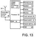
- the interior components of the mobile phone 1such as the battery, printed circuit board, antenna, speaker, inner frame, shielding, etc. are diagrammatically represented by block 30 .
Landscapes
- Engineering & Computer Science (AREA)
- Theoretical Computer Science (AREA)
- General Engineering & Computer Science (AREA)
- Human Computer Interaction (AREA)
- Physics & Mathematics (AREA)
- General Physics & Mathematics (AREA)
- Computer Hardware Design (AREA)
- Signal Processing (AREA)
- Telephone Set Structure (AREA)
- Input From Keyboards Or The Like (AREA)
Abstract
Description
Claims (29)
Priority Applications (6)
| Application Number | Priority Date | Filing Date | Title |
|---|---|---|---|
| US11/472,838US8139035B2 (en) | 2006-06-21 | 2006-06-21 | Touch sensitive keypad with tactile feedback |
| EP11170328.6AEP2367094B1 (en) | 2006-06-21 | 2007-06-12 | Touch sensitive keypad with tactile feedback |
| CN2007800230942ACN101473288B (en) | 2006-06-21 | 2007-06-12 | Touch sensitive keypad, electronic device having the same, and method of registering key strokes and keys |
| PCT/EP2007/005167WO2007147507A2 (en) | 2006-06-21 | 2007-06-12 | Touch sensitive keypad with tactile feedback |
| KR1020087029101AKR100996646B1 (en) | 2006-06-21 | 2007-06-12 | Touch sensitive keypad with tactile feedback |
| EP07764614.9AEP2035910B1 (en) | 2006-06-21 | 2007-06-12 | Touch sensitive keypad with tactile feedback |
Applications Claiming Priority (1)
| Application Number | Priority Date | Filing Date | Title |
|---|---|---|---|
| US11/472,838US8139035B2 (en) | 2006-06-21 | 2006-06-21 | Touch sensitive keypad with tactile feedback |
Publications (2)
| Publication Number | Publication Date |
|---|---|
| US20070296702A1 US20070296702A1 (en) | 2007-12-27 |
| US8139035B2true US8139035B2 (en) | 2012-03-20 |
Family
ID=38474144
Family Applications (1)
| Application Number | Title | Priority Date | Filing Date |
|---|---|---|---|
| US11/472,838Active2028-05-22US8139035B2 (en) | 2006-06-21 | 2006-06-21 | Touch sensitive keypad with tactile feedback |
Country Status (5)
| Country | Link |
|---|---|
| US (1) | US8139035B2 (en) |
| EP (2) | EP2035910B1 (en) |
| KR (1) | KR100996646B1 (en) |
| CN (1) | CN101473288B (en) |
| WO (1) | WO2007147507A2 (en) |
Cited By (6)
| Publication number | Priority date | Publication date | Assignee | Title |
|---|---|---|---|---|
| US20100069940A1 (en)* | 2008-09-12 | 2010-03-18 | Miller Matthew C | Ultrasonic Device for Fingertip Control |
| US20100271315A1 (en)* | 2009-04-28 | 2010-10-28 | Microsoft Corporation | Encoding and decoding adaptive input device inputs |
| US20110095988A1 (en)* | 2009-10-24 | 2011-04-28 | Tara Chand Singhal | Integrated control mechanism for handheld electronic devices |
| US20140346936A1 (en)* | 2013-05-27 | 2014-11-27 | Samsung Electronics Co., Ltd. | Protection cover |
| US9107688B2 (en) | 2008-09-12 | 2015-08-18 | Ethicon Endo-Surgery, Inc. | Activation feature for surgical instrument with pencil grip |
| US20180329444A1 (en)* | 2015-10-23 | 2018-11-15 | Behr-Hella Thermocontrol Gmbh | Operating unit for a vehicle component, in particular for a heating, ventilation and/or air conditioning system |
Families Citing this family (120)
| Publication number | Priority date | Publication date | Assignee | Title |
|---|---|---|---|---|
| US7333092B2 (en) | 2002-02-25 | 2008-02-19 | Apple Computer, Inc. | Touch pad for handheld device |
| KR101129272B1 (en)* | 2006-03-13 | 2012-03-26 | 엘지전자 주식회사 | Keypad assembly and mobile terminal having the same |
| USD589919S1 (en)* | 2006-06-14 | 2009-04-07 | Nokia Corporation | Handset |
| US8022935B2 (en) | 2006-07-06 | 2011-09-20 | Apple Inc. | Capacitance sensing electrode with integrated I/O mechanism |
| EP2052313A2 (en)* | 2006-08-17 | 2009-04-29 | Nokia Corporation | Scrollbar and touchpad with tactile and/or audible feedback |
| US8274479B2 (en) | 2006-10-11 | 2012-09-25 | Apple Inc. | Gimballed scroll wheel |
| CA121359S (en)* | 2007-01-19 | 2008-02-21 | Nokia Corp | Handset |
| US7973763B2 (en)* | 2007-04-13 | 2011-07-05 | Htc Corporation | Electronic devices with sensible orientation structures, and associated methods |
| US8319670B2 (en)* | 2007-06-12 | 2012-11-27 | Elektrobit Wireless Communications Oy | Input arrangement |
| AU318969S (en)* | 2007-06-20 | 2008-04-21 | Nokia Corp | Key buttons for a handset |
| TWM327128U (en)* | 2007-07-05 | 2008-02-11 | D Link Corp | Network device having display unit |
| US20090009480A1 (en)* | 2007-07-06 | 2009-01-08 | Sony Ericsson Mobile Communications Ab | Keypad with tactile touch glass |
| US9442584B2 (en)* | 2007-07-30 | 2016-09-13 | Qualcomm Incorporated | Electronic device with reconfigurable keypad |
| US20090046065A1 (en)* | 2007-08-17 | 2009-02-19 | Eric Liu | Sensor-keypad combination for mobile computing devices and applications thereof |
| CN101388962A (en)* | 2007-09-11 | 2009-03-18 | 鸿富锦精密工业(深圳)有限公司 | Button function automatic switching system and method |
| USD585862S1 (en)* | 2007-11-13 | 2009-02-03 | Nokia Corporation | Handset |
| US20090153490A1 (en)* | 2007-12-12 | 2009-06-18 | Nokia Corporation | Signal adaptation in response to orientation or movement of a mobile electronic device |
| JP5127840B2 (en)* | 2007-12-14 | 2013-01-23 | 富士通株式会社 | Display panel structure, electronic device using the same, and portable information device |
| US8243038B2 (en) | 2009-07-03 | 2012-08-14 | Tactus Technologies | Method for adjusting the user interface of a device |
| US8553005B2 (en) | 2008-01-04 | 2013-10-08 | Tactus Technology, Inc. | User interface system |
| US9274612B2 (en) | 2008-01-04 | 2016-03-01 | Tactus Technology, Inc. | User interface system |
| US9720501B2 (en) | 2008-01-04 | 2017-08-01 | Tactus Technology, Inc. | Dynamic tactile interface |
| US8922510B2 (en) | 2008-01-04 | 2014-12-30 | Tactus Technology, Inc. | User interface system |
| US9557915B2 (en) | 2008-01-04 | 2017-01-31 | Tactus Technology, Inc. | Dynamic tactile interface |
| US9052790B2 (en) | 2008-01-04 | 2015-06-09 | Tactus Technology, Inc. | User interface and methods |
| US8456438B2 (en) | 2008-01-04 | 2013-06-04 | Tactus Technology, Inc. | User interface system |
| US9423875B2 (en) | 2008-01-04 | 2016-08-23 | Tactus Technology, Inc. | Dynamic tactile interface with exhibiting optical dispersion characteristics |
| US9430074B2 (en) | 2008-01-04 | 2016-08-30 | Tactus Technology, Inc. | Dynamic tactile interface |
| US9588683B2 (en) | 2008-01-04 | 2017-03-07 | Tactus Technology, Inc. | Dynamic tactile interface |
| US8947383B2 (en) | 2008-01-04 | 2015-02-03 | Tactus Technology, Inc. | User interface system and method |
| US8179377B2 (en) | 2009-01-05 | 2012-05-15 | Tactus Technology | User interface system |
| US20160187981A1 (en) | 2008-01-04 | 2016-06-30 | Tactus Technology, Inc. | Manual fluid actuator |
| US9298261B2 (en) | 2008-01-04 | 2016-03-29 | Tactus Technology, Inc. | Method for actuating a tactile interface layer |
| US9612659B2 (en) | 2008-01-04 | 2017-04-04 | Tactus Technology, Inc. | User interface system |
| US8179375B2 (en) | 2008-01-04 | 2012-05-15 | Tactus Technology | User interface system and method |
| US9552065B2 (en) | 2008-01-04 | 2017-01-24 | Tactus Technology, Inc. | Dynamic tactile interface |
| US8570295B2 (en) | 2008-01-04 | 2013-10-29 | Tactus Technology, Inc. | User interface system |
| US8704790B2 (en) | 2010-10-20 | 2014-04-22 | Tactus Technology, Inc. | User interface system |
| US9128525B2 (en) | 2008-01-04 | 2015-09-08 | Tactus Technology, Inc. | Dynamic tactile interface |
| US8547339B2 (en)* | 2008-01-04 | 2013-10-01 | Tactus Technology, Inc. | System and methods for raised touch screens |
| US8154527B2 (en) | 2008-01-04 | 2012-04-10 | Tactus Technology | User interface system |
| US9063627B2 (en) | 2008-01-04 | 2015-06-23 | Tactus Technology, Inc. | User interface and methods |
| US8982055B2 (en)* | 2008-01-15 | 2015-03-17 | Sony Corporation | Wireless mobile communication terminals and methods for forming the same |
| USD597539S1 (en)* | 2008-02-29 | 2009-08-04 | Nokia Corporation | Front cover of a handset |
| USD591281S1 (en)* | 2008-02-29 | 2009-04-28 | Nokia Corporation | Front cover of a handset |
| USD589484S1 (en)* | 2008-02-29 | 2009-03-31 | Nokia Corporation | Handset |
| EP2104020A1 (en)* | 2008-03-20 | 2009-09-23 | British Telecmmunications public limited campany | A device |
| USD592654S1 (en)* | 2008-03-27 | 2009-05-19 | Nokia Corporation | Front cover for a handset |
| USD596153S1 (en)* | 2008-03-27 | 2009-07-14 | Nokia Corporation | Handset |
| USD637986S1 (en)* | 2008-04-14 | 2011-05-17 | Nokia Corporation | Handset |
| USD613706S1 (en)* | 2008-06-06 | 2010-04-13 | Nokia Corporation | Handset |
| USD608324S1 (en)* | 2008-06-06 | 2010-01-19 | Nokia Corporation | Handset |
| USD609702S1 (en)* | 2008-06-30 | 2010-02-09 | Nokia Corporation | Set of keys for a handset |
| USD609668S1 (en)* | 2008-08-29 | 2010-02-09 | Fih (Hong Kong) Limited | Mobile phone |
| USD616406S1 (en)* | 2008-09-19 | 2010-05-25 | Fih (Hong Kong) Limited | Mobile phone |
| USD598419S1 (en)* | 2008-10-31 | 2009-08-18 | Nokia Corporation | Handset |
| US20100123676A1 (en)* | 2008-11-17 | 2010-05-20 | Kevin Scott Kirkup | Dual input keypad for a portable electronic device |
| US9588684B2 (en) | 2009-01-05 | 2017-03-07 | Tactus Technology, Inc. | Tactile interface for a computing device |
| WO2010078596A1 (en) | 2009-01-05 | 2010-07-08 | Tactus Technology, Inc. | User interface system |
| USD606062S1 (en)* | 2009-02-17 | 2009-12-15 | Nokia Corporation | Handset |
| USD605644S1 (en)* | 2009-02-17 | 2009-12-08 | Nokia Corporation | Handset |
| USD608355S1 (en)* | 2009-03-06 | 2010-01-19 | Nokia Corporation | Handset front cover |
| US8674951B2 (en) | 2009-06-16 | 2014-03-18 | Intel Corporation | Contoured thumb touch sensor apparatus |
| USD617292S1 (en)* | 2009-06-18 | 2010-06-08 | Cheng Uei Precision Industry Co., Ltd. | Mobile phone |
| WO2011003113A1 (en) | 2009-07-03 | 2011-01-06 | Tactus Technology | User interface enhancement system |
| TW201104523A (en)* | 2009-07-22 | 2011-02-01 | Wistron Corp | Modular touch control assembly and electronic device having the same |
| WO2011087816A1 (en) | 2009-12-21 | 2011-07-21 | Tactus Technology | User interface system |
| CN102782617B (en) | 2009-12-21 | 2015-10-07 | 泰克图斯科技公司 | User interface system |
| US9298262B2 (en) | 2010-01-05 | 2016-03-29 | Tactus Technology, Inc. | Dynamic tactile interface |
| USD631454S1 (en)* | 2010-01-07 | 2011-01-25 | Fih (Hong Kong) Limited | Mobile phone |
| US8619035B2 (en) | 2010-02-10 | 2013-12-31 | Tactus Technology, Inc. | Method for assisting user input to a device |
| US9092056B2 (en)* | 2010-02-22 | 2015-07-28 | Panasonic Corporation Of North America | Keyboard having selectively viewable glyphs |
| WO2011112984A1 (en) | 2010-03-11 | 2011-09-15 | Tactus Technology | User interface system |
| USD628185S1 (en)* | 2010-04-12 | 2010-11-30 | Nokia Corporation | Handset |
| USD630609S1 (en)* | 2010-04-15 | 2011-01-11 | Nokia Corporation | Handset |
| WO2011133605A1 (en) | 2010-04-19 | 2011-10-27 | Tactus Technology | Method of actuating a tactile interface layer |
| WO2011133604A1 (en) | 2010-04-19 | 2011-10-27 | Tactus Technology | User interface system |
| CN102262464B (en)* | 2010-05-25 | 2014-10-29 | 深圳富泰宏精密工业有限公司 | Touch transparent keyboard |
| EP2390765A1 (en)* | 2010-05-27 | 2011-11-30 | Research In Motion Limited | Touch-sensitive display |
| CN103124946B (en) | 2010-10-20 | 2016-06-29 | 泰克图斯科技公司 | User interface system and method |
| WO2012055563A1 (en)* | 2010-10-28 | 2012-05-03 | Marquardt Gmbh | Switch control panel |
| US9029723B2 (en) | 2010-12-30 | 2015-05-12 | Blackberry Limited | Keypad apparatus and methods |
| US9636582B2 (en) | 2011-04-18 | 2017-05-02 | Microsoft Technology Licensing, Llc | Text entry by training touch models |
| US9069394B2 (en) | 2012-03-20 | 2015-06-30 | Google Inc. | Fully clickable trackpad |
| WO2014047656A2 (en) | 2012-09-24 | 2014-03-27 | Tactus Technology, Inc. | Dynamic tactile interface and methods |
| US9405417B2 (en) | 2012-09-24 | 2016-08-02 | Tactus Technology, Inc. | Dynamic tactile interface and methods |
| US9330544B2 (en)* | 2012-11-20 | 2016-05-03 | Immersion Corporation | System and method for simulated physical interactions with haptic effects |
| USD709848S1 (en)* | 2013-02-12 | 2014-07-29 | Nokia Corporation | Handset |
| USD745508S1 (en) | 2013-03-15 | 2015-12-15 | Intel Corporation | Computing device with sensor |
| USD732526S1 (en) | 2013-04-16 | 2015-06-23 | Intel Corporation | Computing device with sensor |
| USD720323S1 (en)* | 2013-06-20 | 2014-12-30 | Nokia Corporation | Handset |
| US9557813B2 (en) | 2013-06-28 | 2017-01-31 | Tactus Technology, Inc. | Method for reducing perceived optical distortion |
| USD720714S1 (en)* | 2013-07-01 | 2015-01-06 | Nokia Corporation | Handset |
| USD737237S1 (en)* | 2013-07-01 | 2015-08-25 | Microsoft Mobile Oy | Handset |
| EP3014400B1 (en) | 2013-08-09 | 2020-06-03 | Apple Inc. | Tactile switch for an electronic device |
| USD720715S1 (en)* | 2013-11-07 | 2015-01-06 | Nokia Corporation | Handset |
| US10048802B2 (en) | 2014-02-12 | 2018-08-14 | Apple Inc. | Rejection of false turns of rotary inputs for electronic devices |
| US9335848B2 (en)* | 2014-02-14 | 2016-05-10 | Lenovo Enterprise Solutions (Singapore) Pte. Ltd. | Apparatus for providing a three dimensional tactile display of an electronic device |
| USD721672S1 (en)* | 2014-02-19 | 2015-01-27 | Nokia Corporation | Handset |
| US9304599B2 (en) | 2014-03-21 | 2016-04-05 | Dell Products L.P. | Gesture controlled adaptive projected information handling system input and output devices |
| EP3251139B1 (en) | 2015-03-08 | 2021-04-28 | Apple Inc. | Compressible seal for rotatable and translatable input mechanisms |
| EP3286775B1 (en)* | 2015-04-20 | 2021-05-19 | Lutron Technology Company LLC | Control devices having independently suspended buttons for controlled actuation |
| US9898095B2 (en)* | 2015-06-29 | 2018-02-20 | Synaptics Incorporated | Low-profile capacitive pointing stick |
| USD795830S1 (en)* | 2015-10-22 | 2017-08-29 | Microsoft Corporation | Handset |
| USD793983S1 (en)* | 2016-01-04 | 2017-08-08 | Microsoft Corporation | Handset |
| US10061399B2 (en) | 2016-07-15 | 2018-08-28 | Apple Inc. | Capacitive gap sensor ring for an input device |
| US10019097B2 (en) | 2016-07-25 | 2018-07-10 | Apple Inc. | Force-detecting input structure |
| USD803807S1 (en)* | 2016-07-29 | 2017-11-28 | Hmd Global Oy | Handset |
| KR102410937B1 (en) | 2017-04-18 | 2022-06-20 | 현대자동차주식회사 | Card type smart key and control method thereof |
| US10962935B1 (en) | 2017-07-18 | 2021-03-30 | Apple Inc. | Tri-axis force sensor |
| US11360440B2 (en) | 2018-06-25 | 2022-06-14 | Apple Inc. | Crown for an electronic watch |
| US11561515B2 (en) | 2018-08-02 | 2023-01-24 | Apple Inc. | Crown for an electronic watch |
| CN211293787U (en) | 2018-08-24 | 2020-08-18 | 苹果公司 | Electronic watch |
| CN209625187U (en) | 2018-08-30 | 2019-11-12 | 苹果公司 | Electronic Watches and Electronic Devices |
| US11194299B1 (en) | 2019-02-12 | 2021-12-07 | Apple Inc. | Variable frictional feedback device for a digital crown of an electronic watch |
| US11550268B2 (en) | 2020-06-02 | 2023-01-10 | Apple Inc. | Switch module for electronic crown assembly |
| US11775099B2 (en) | 2020-10-16 | 2023-10-03 | Samsung Electro-Mechanics Co., Ltd. | Touch sensing module and electronic device including the same |
| US12092996B2 (en) | 2021-07-16 | 2024-09-17 | Apple Inc. | Laser-based rotation sensor for a crown of an electronic watch |
| FR3126138B1 (en)* | 2021-08-16 | 2023-08-04 | Somfy Activites Sa | Manual control device in which the return of the control button is done by a toroidal element |
| US12189347B2 (en) | 2022-06-14 | 2025-01-07 | Apple Inc. | Rotation sensor for a crown of an electronic watch |
Citations (21)
| Publication number | Priority date | Publication date | Assignee | Title |
|---|---|---|---|---|
| US4088855A (en)* | 1977-02-28 | 1978-05-09 | Korry Manufacturing Co. | Keyboard electro-mechanical switch with coil spring contact |
| US4500758A (en)* | 1983-07-05 | 1985-02-19 | Hewlett-Packard Company | Keyboard switch assembly having sensory feedback |
| DE9105230U1 (en) | 1991-04-27 | 1991-07-04 | Alcatel Sel Ag, 70435 Stuttgart | Push button switch with lighting |
| US5138119A (en)* | 1991-03-15 | 1992-08-11 | Lucas Duralith Corporation | Backlit tactile keyboard with improved tactile and electrical characteristics |
| US5140116A (en) | 1989-09-19 | 1992-08-18 | Schmitt Walter Stefan | Illuminated push-button switch |
| US5887995A (en) | 1997-09-23 | 1999-03-30 | Compaq Computer Corporation | Touchpad overlay with tactile response |
| US5917906A (en) | 1997-10-01 | 1999-06-29 | Ericsson Inc. | Touch pad with tactile feature |
| JP2000200141A (en) | 1999-01-01 | 2000-07-18 | Smk Corp | Tablet with switch |
| US6118435A (en)* | 1997-04-10 | 2000-09-12 | Idec Izumi Corporation | Display unit with touch panel |
| US20020021280A1 (en)* | 2000-08-11 | 2002-02-21 | Alps Electric Co., Ltd. | Input device which allows button input operation and coordinate input operation to be performed in the same operation plane |
| US20030011972A1 (en) | 2001-07-13 | 2003-01-16 | Koo Ja-Goun | Control of LCD display backlight by actuation of a latch in a notebook computer |
| WO2003100092A2 (en) | 2002-05-28 | 2003-12-04 | Evotec Neurosciences Gmbh | Diagnostic and therapeutic use of cyp11a1 for neurodegenerative diseases |
| WO2004107146A2 (en) | 2003-05-30 | 2004-12-09 | Therefore Limited | A data input method for a computing device |
| EP1513055A2 (en) | 2001-08-10 | 2005-03-09 | Alps Electric Co., Ltd. | Input apparatus for performing input operation corresponding to indication marks and coordinate input operation on the same operational plane |
| US20050052425A1 (en)* | 2003-08-18 | 2005-03-10 | Zadesky Stephen Paul | Movable touch pad with added functionality |
| DE102004040395A1 (en) | 2003-08-23 | 2005-03-24 | Marquardt Gmbh | Electrical switch used as short-stroke key for keyboard or operating field has housing base provided with recess on its underside receiving projections of housing cover side edge |
| US20060034042A1 (en)* | 2004-08-10 | 2006-02-16 | Kabushiki Kaisha Toshiba | Electronic apparatus having universal human interface |
| US20060079279A1 (en) | 2004-10-13 | 2006-04-13 | Hsuan-Yu Lin | Mobille phone having the function of a mouse |
| US20060238514A1 (en)* | 2005-04-26 | 2006-10-26 | Rosenberg Paul K | Slide pad membrane |
| US7279647B2 (en)* | 2005-06-17 | 2007-10-09 | Harald Philipp | Control panel |
| US20070236472A1 (en)* | 2006-04-10 | 2007-10-11 | Microsoft Corporation | Universal user interface device |
Family Cites Families (1)
| Publication number | Priority date | Publication date | Assignee | Title |
|---|---|---|---|---|
| US7636748B2 (en)* | 2003-09-29 | 2009-12-22 | Microsoft Corporation | Display configurations for a data processing device |
- 2006
- 2006-06-21USUS11/472,838patent/US8139035B2/enactiveActive
- 2007
- 2007-06-12CNCN2007800230942Apatent/CN101473288B/enactiveActive
- 2007-06-12WOPCT/EP2007/005167patent/WO2007147507A2/enactiveApplication Filing
- 2007-06-12EPEP07764614.9Apatent/EP2035910B1/enactiveActive
- 2007-06-12EPEP11170328.6Apatent/EP2367094B1/ennot_activeNot-in-force
- 2007-06-12KRKR1020087029101Apatent/KR100996646B1/ennot_activeExpired - Fee Related
Patent Citations (21)
| Publication number | Priority date | Publication date | Assignee | Title |
|---|---|---|---|---|
| US4088855A (en)* | 1977-02-28 | 1978-05-09 | Korry Manufacturing Co. | Keyboard electro-mechanical switch with coil spring contact |
| US4500758A (en)* | 1983-07-05 | 1985-02-19 | Hewlett-Packard Company | Keyboard switch assembly having sensory feedback |
| US5140116A (en) | 1989-09-19 | 1992-08-18 | Schmitt Walter Stefan | Illuminated push-button switch |
| US5138119A (en)* | 1991-03-15 | 1992-08-11 | Lucas Duralith Corporation | Backlit tactile keyboard with improved tactile and electrical characteristics |
| DE9105230U1 (en) | 1991-04-27 | 1991-07-04 | Alcatel Sel Ag, 70435 Stuttgart | Push button switch with lighting |
| US6118435A (en)* | 1997-04-10 | 2000-09-12 | Idec Izumi Corporation | Display unit with touch panel |
| US5887995A (en) | 1997-09-23 | 1999-03-30 | Compaq Computer Corporation | Touchpad overlay with tactile response |
| US5917906A (en) | 1997-10-01 | 1999-06-29 | Ericsson Inc. | Touch pad with tactile feature |
| JP2000200141A (en) | 1999-01-01 | 2000-07-18 | Smk Corp | Tablet with switch |
| US20020021280A1 (en)* | 2000-08-11 | 2002-02-21 | Alps Electric Co., Ltd. | Input device which allows button input operation and coordinate input operation to be performed in the same operation plane |
| US20030011972A1 (en) | 2001-07-13 | 2003-01-16 | Koo Ja-Goun | Control of LCD display backlight by actuation of a latch in a notebook computer |
| EP1513055A2 (en) | 2001-08-10 | 2005-03-09 | Alps Electric Co., Ltd. | Input apparatus for performing input operation corresponding to indication marks and coordinate input operation on the same operational plane |
| WO2003100092A2 (en) | 2002-05-28 | 2003-12-04 | Evotec Neurosciences Gmbh | Diagnostic and therapeutic use of cyp11a1 for neurodegenerative diseases |
| WO2004107146A2 (en) | 2003-05-30 | 2004-12-09 | Therefore Limited | A data input method for a computing device |
| US20050052425A1 (en)* | 2003-08-18 | 2005-03-10 | Zadesky Stephen Paul | Movable touch pad with added functionality |
| DE102004040395A1 (en) | 2003-08-23 | 2005-03-24 | Marquardt Gmbh | Electrical switch used as short-stroke key for keyboard or operating field has housing base provided with recess on its underside receiving projections of housing cover side edge |
| US20060034042A1 (en)* | 2004-08-10 | 2006-02-16 | Kabushiki Kaisha Toshiba | Electronic apparatus having universal human interface |
| US20060079279A1 (en) | 2004-10-13 | 2006-04-13 | Hsuan-Yu Lin | Mobille phone having the function of a mouse |
| US20060238514A1 (en)* | 2005-04-26 | 2006-10-26 | Rosenberg Paul K | Slide pad membrane |
| US7279647B2 (en)* | 2005-06-17 | 2007-10-09 | Harald Philipp | Control panel |
| US20070236472A1 (en)* | 2006-04-10 | 2007-10-11 | Microsoft Corporation | Universal user interface device |
Non-Patent Citations (2)
| Title |
|---|
| EP Office Action , Application No. 06 776 914.1-1527, Sep. 27, 2010, 7 pgs. |
| International Search Report, Application No. PCT/EP2006/008110 mailed Mar. 27, 2008, 13 pgs. |
Cited By (7)
| Publication number | Priority date | Publication date | Assignee | Title |
|---|---|---|---|---|
| US20100069940A1 (en)* | 2008-09-12 | 2010-03-18 | Miller Matthew C | Ultrasonic Device for Fingertip Control |
| US9023071B2 (en)* | 2008-09-12 | 2015-05-05 | Ethicon Endo-Surgery, Inc. | Ultrasonic device for fingertip control |
| US9107688B2 (en) | 2008-09-12 | 2015-08-18 | Ethicon Endo-Surgery, Inc. | Activation feature for surgical instrument with pencil grip |
| US20100271315A1 (en)* | 2009-04-28 | 2010-10-28 | Microsoft Corporation | Encoding and decoding adaptive input device inputs |
| US20110095988A1 (en)* | 2009-10-24 | 2011-04-28 | Tara Chand Singhal | Integrated control mechanism for handheld electronic devices |
| US20140346936A1 (en)* | 2013-05-27 | 2014-11-27 | Samsung Electronics Co., Ltd. | Protection cover |
| US20180329444A1 (en)* | 2015-10-23 | 2018-11-15 | Behr-Hella Thermocontrol Gmbh | Operating unit for a vehicle component, in particular for a heating, ventilation and/or air conditioning system |
Also Published As
| Publication number | Publication date |
|---|---|
| US20070296702A1 (en) | 2007-12-27 |
| KR20080111563A (en) | 2008-12-23 |
| KR100996646B1 (en) | 2010-11-25 |
| CN101473288A (en) | 2009-07-01 |
| CN101473288B (en) | 2012-04-11 |
| EP2035910B1 (en) | 2013-05-22 |
| WO2007147507A3 (en) | 2008-04-17 |
| EP2367094A1 (en) | 2011-09-21 |
| EP2367094B1 (en) | 2013-04-24 |
| WO2007147507A2 (en) | 2007-12-27 |
| EP2035910A2 (en) | 2009-03-18 |
Similar Documents
| Publication | Publication Date | Title |
|---|---|---|
| US8139035B2 (en) | Touch sensitive keypad with tactile feedback | |
| US7010333B2 (en) | Radiotelephone terminal with dual-sided keypad apparatus | |
| US20070287512A1 (en) | Layered mobile device | |
| US20080051041A1 (en) | Hybrid portrait-landscape handheld device with trackball navigation and qwerty hide-away keyboard | |
| EP1887597B1 (en) | Mobile terminal | |
| CN101529873A (en) | Electronic device with keypad assembly | |
| WO2008028499A1 (en) | Mobile electronic device with competing input devices | |
| US20050277448A1 (en) | Soft buttons on LCD module with tactile feedback | |
| US20080080919A1 (en) | Three row qwerty keyboard layout for compact landscape portable handheld messaging devices | |
| US8401597B2 (en) | Mobile terminal device | |
| JP2006065611A (en) | Input device and input system using the same | |
| US20110043476A1 (en) | Scrollbar and Touchpad with Tactile and/or Audible Feedback | |
| US8350728B2 (en) | Keyboard with integrated and numeric keypad | |
| CN102630134B (en) | Electronic mobile device seamless key/display structure | |
| EP1895382A1 (en) | Three row qwerty keyboard layout for compact landscape portable handheld messaging devices | |
| US8643604B2 (en) | Seamless button array panels for handheld communication devices | |
| WO2008055513A1 (en) | Wireless mobile communication terminal with adaptive user interface | |
| CN101122809A (en) | Handheld electronic device and operation method thereof | |
| EP1895381A1 (en) | Hybrid portrait-landscape handheld device with trackball navigation and qwerty hide-away keyboard | |
| US8749962B2 (en) | Keypad assembly with a contoured keypad facade for a mobile computing device | |
| JP2006217261A (en) | Small electronic equipment | |
| HK1111789A (en) | Three row qwerty keyboard layout for compact landscape portable handheld messaging devices | |
| HK1112078A (en) | Hybrid portrait-landscape handheld device with trackball navigation and qwerty hide-away keyboard |
Legal Events
| Date | Code | Title | Description |
|---|---|---|---|
| AS | Assignment | Owner name:NOKIA CORPORATION, FINLAND Free format text:ASSIGNMENT OF ASSIGNORS INTEREST;ASSIGNORS:STRAWN, ANDREW;BICK, ANDREW RAYMOND;REEL/FRAME:018417/0193 Effective date:20060815 Owner name:NOKIA CORPORATION, FINLAND Free format text:ASSIGNMENT OF ASSIGNORS INTEREST;ASSIGNORS:LEITH, DAREN;BRADFORD, SIMON;MILES, LUKE;AND OTHERS;REEL/FRAME:018417/0200;SIGNING DATES FROM 20060807 TO 20060920 Owner name:NOKIA CORPORATION, FINLAND Free format text:ASSIGNMENT OF ASSIGNORS INTEREST;ASSIGNOR:TOMPKIN, CRISPIAN GRANT;REEL/FRAME:018417/0340 Effective date:20061002 Owner name:NOKIA CORPORATION, FINLAND Free format text:ASSIGNMENT OF ASSIGNORS INTEREST;ASSIGNORS:LEITH, DAREN;BRADFORD, SIMON;MILES, LUKE;AND OTHERS;SIGNING DATES FROM 20060807 TO 20060920;REEL/FRAME:018417/0200 | |
| FEPP | Fee payment procedure | Free format text:PAYOR NUMBER ASSIGNED (ORIGINAL EVENT CODE: ASPN); ENTITY STATUS OF PATENT OWNER: LARGE ENTITY | |
| STCF | Information on status: patent grant | Free format text:PATENTED CASE | |
| AS | Assignment | Owner name:NOKIA TECHNOLOGIES OY, FINLAND Free format text:ASSIGNMENT OF ASSIGNORS INTEREST;ASSIGNOR:NOKIA CORPORATION;REEL/FRAME:035603/0543 Effective date:20150116 | |
| FPAY | Fee payment | Year of fee payment:4 | |
| MAFP | Maintenance fee payment | Free format text:PAYMENT OF MAINTENANCE FEE, 8TH YEAR, LARGE ENTITY (ORIGINAL EVENT CODE: M1552); ENTITY STATUS OF PATENT OWNER: LARGE ENTITY Year of fee payment:8 | |
| MAFP | Maintenance fee payment | Free format text:PAYMENT OF MAINTENANCE FEE, 12TH YEAR, LARGE ENTITY (ORIGINAL EVENT CODE: M1553); ENTITY STATUS OF PATENT OWNER: LARGE ENTITY Year of fee payment:12 |