US8138925B2 - RFID systems and methods for automatically detecting and/or directing the physical configuration of a complex system - Google Patents
RFID systems and methods for automatically detecting and/or directing the physical configuration of a complex systemDownload PDFInfo
- Publication number
- US8138925B2 US8138925B2US12/354,335US35433509AUS8138925B2US 8138925 B2US8138925 B2US 8138925B2US 35433509 AUS35433509 AUS 35433509AUS 8138925 B2US8138925 B2US 8138925B2
- Authority
- US
- United States
- Prior art keywords
- mateable
- rfid
- components
- rfid tag
- information
- Prior art date
- Legal status (The legal status is an assumption and is not a legal conclusion. Google has not performed a legal analysis and makes no representation as to the accuracy of the status listed.)
- Active, expires
Links
Images


Classifications
- G—PHYSICS
- G06—COMPUTING OR CALCULATING; COUNTING
- G06K—GRAPHICAL DATA READING; PRESENTATION OF DATA; RECORD CARRIERS; HANDLING RECORD CARRIERS
- G06K17/00—Methods or arrangements for effecting co-operative working between equipments covered by two or more of main groups G06K1/00 - G06K15/00, e.g. automatic card files incorporating conveying and reading operations
- G06K17/0003—Automatic card files incorporating selecting, conveying and possibly reading and/or writing operations
- G06K17/0006—Automatic card files incorporating selecting, conveying and possibly reading and/or writing operations with random access selection of a record carrier from the card-file, e.g. the carriers are suspended on the selection device which in part of the card magazine
- G—PHYSICS
- G06—COMPUTING OR CALCULATING; COUNTING
- G06K—GRAPHICAL DATA READING; PRESENTATION OF DATA; RECORD CARRIERS; HANDLING RECORD CARRIERS
- G06K19/00—Record carriers for use with machines and with at least a part designed to carry digital markings
- G06K19/06—Record carriers for use with machines and with at least a part designed to carry digital markings characterised by the kind of the digital marking, e.g. shape, nature, code
- G06K19/067—Record carriers with conductive marks, printed circuits or semiconductor circuit elements, e.g. credit or identity cards also with resonating or responding marks without active components
- G06K19/07—Record carriers with conductive marks, printed circuits or semiconductor circuit elements, e.g. credit or identity cards also with resonating or responding marks without active components with integrated circuit chips
- G06K19/0716—Record carriers with conductive marks, printed circuits or semiconductor circuit elements, e.g. credit or identity cards also with resonating or responding marks without active components with integrated circuit chips at least one of the integrated circuit chips comprising a sensor or an interface to a sensor
- G06K19/0717—Record carriers with conductive marks, printed circuits or semiconductor circuit elements, e.g. credit or identity cards also with resonating or responding marks without active components with integrated circuit chips at least one of the integrated circuit chips comprising a sensor or an interface to a sensor the sensor being capable of sensing environmental conditions such as temperature history or pressure
- G—PHYSICS
- G06—COMPUTING OR CALCULATING; COUNTING
- G06K—GRAPHICAL DATA READING; PRESENTATION OF DATA; RECORD CARRIERS; HANDLING RECORD CARRIERS
- G06K19/00—Record carriers for use with machines and with at least a part designed to carry digital markings
- G06K19/06—Record carriers for use with machines and with at least a part designed to carry digital markings characterised by the kind of the digital marking, e.g. shape, nature, code
- G06K19/067—Record carriers with conductive marks, printed circuits or semiconductor circuit elements, e.g. credit or identity cards also with resonating or responding marks without active components
- G06K19/07—Record carriers with conductive marks, printed circuits or semiconductor circuit elements, e.g. credit or identity cards also with resonating or responding marks without active components with integrated circuit chips
- G06K19/0723—Record carriers with conductive marks, printed circuits or semiconductor circuit elements, e.g. credit or identity cards also with resonating or responding marks without active components with integrated circuit chips the record carrier comprising an arrangement for non-contact communication, e.g. wireless communication circuits on transponder cards, non-contact smart cards or RFIDs
- G—PHYSICS
- G06—COMPUTING OR CALCULATING; COUNTING
- G06K—GRAPHICAL DATA READING; PRESENTATION OF DATA; RECORD CARRIERS; HANDLING RECORD CARRIERS
- G06K5/00—Methods or arrangements for verifying the correctness of markings on a record carrier; Column detection devices
- G06K5/02—Methods or arrangements for verifying the correctness of markings on a record carrier; Column detection devices the verifying forming a part of the marking action
- H—ELECTRICITY
- H05—ELECTRIC TECHNIQUES NOT OTHERWISE PROVIDED FOR
- H05K—PRINTED CIRCUITS; CASINGS OR CONSTRUCTIONAL DETAILS OF ELECTRIC APPARATUS; MANUFACTURE OF ASSEMBLAGES OF ELECTRICAL COMPONENTS
- H05K7/00—Constructional details common to different types of electric apparatus
- H05K7/14—Mounting supporting structure in casing or on frame or rack
- H05K7/1485—Servers; Data center rooms, e.g. 19-inch computer racks
- H05K7/1498—Resource management, Optimisation arrangements, e.g. configuration, identification, tracking, physical location
- H—ELECTRICITY
- H04—ELECTRIC COMMUNICATION TECHNIQUE
- H04Q—SELECTING
- H04Q1/00—Details of selecting apparatus or arrangements
- H04Q1/02—Constructional details
- H04Q1/14—Distribution frames
- H04Q1/149—Wireguides in connector blocks
Definitions
- the technology of the disclosurerelates generally to the use of radio-frequency identification (RFID) systems, and in particular is directed to RFID-based systems and methods for automatically detecting, directing, and/or configuring the physical configuration of a complex system, such as a telecommunications system.
- RFIDradio-frequency identification
- Typical telecommunications data centersinclude large numbers of optical and electrical cable connections that join various types of network equipment.
- network equipmentinclude electrically-powered (active) units such as servers, switches and routers, and unpowered (passive) units such as fanout boxes and patch panels.
- This network equipmentis often installed within cabinets in standard (e.g., 19′′) equipment racks.
- Each piece of equipmenttypically provides one or more adapters where optical or electrical patch cables can be physically connected to the equipment.
- These patch cablesare generally routed to other network equipment located in the same cabinet or to another cabinet.
- a common issue in telecommunications data center managementis determining the current configuration of all the optical and electrical links among all the network hardware equipment.
- the configuration of optical and electrical linkscan be completely determined if the physical locations of all connected patch cable connectors on installed network equipment are known.
- a patch cable that contains a transmit optical fiber and a receive optical fiberneeds to be connected to the corresponding adapter in the proper orientation or “polarization” so that the transmit/receive process can occur.
- a first aspect disclosed in the detailed descriptionis a radio-frequency identification (RFID) system for detecting, directing, and/or configuring a configuration of a complex system having a set of one or more types of mateable components.
- the systemincludes a set of mateable RFID tags arranged so that each mateable component in the set includes at least one mateable RFID tag.
- the mateable RFID tagsinclude information relating to their associated mateable components and are arranged so that the mating of components results in the mating of the corresponding RFID tags.
- the RFID systemincludes at least one RFID reader adapted to read an RFID tag signal sent from at least one RFID tag in a mated pair of RFID tags, wherein the at least one RFID tag signal contains information about the mated components.
- the RFID systemalso includes an information processing system operably connected to the at least one RFID reader.
- the information processing systemis adapted to receive and process information therefrom to establish a number and type of mated connections that constitute the complex system configuration.
- the information processing systemis also optionally adapted to provide directions for configuring the system so that an end-user can configure the complex system.
- a second aspect disclosed in the detailed descriptionis an RFID configuration detection system for detecting, directing, and/or configuring a configuration of a complex system having a set of one or more types of mateable components.
- the RFID systemincludes at least one mateable RFID tag associated with each mateable component in the set of mateable components and having an antenna electrically connected to an integrated circuit (IC) chip.
- the IC chipis adapted to store information that includes information relating to its associated mateable component.
- the at least one mateable RFID tagis arranged relative to its associated component such that mating two mateable components causes the corresponding at least one mateable RFID tag associated with the two mateable components to mate and exchange the information stored therein, and to communicate information regarding their mated status via at least one wireless RFID tag signal.
- the RFID systemincludes at least one RFID reader adapted to receive the at least one wireless RFID tag signal from each mated pair of components.
- the RFID systemalso includes an information processing system operably connected to the at least one RFID reader.
- the information processing systemis adapted to receive therefrom and process said mated status information to determine the complex system configuration.
- the information processing systemis also optionally adapted to provide directions for configuring the system so that an end-user can configure the complex system.
- a third aspect disclosed in the detailed descriptionis an RFID-based method of detecting and/or directing a configuration of a complex system having a set of one or more types of mateable components.
- the methodincludes providing each mateable component in the set with at least one mateable RFID tag that includes information about its associated mateable component, including arranging the at least one mateable RFID tag so that when two mateable components mate, the corresponding mateable RFID tags mate and exchange information about their respective mateable components.
- the methodalso includes mating a number of mateable components so as to cause the corresponding mateable RFID tags to mate and exchange information about their respective mateable component.
- the methodfurther includes, for each pair of mated components, generating at least one RFID tag signal that includes information relating to the mated components.
- the methodfurther includes receiving and processing the at least one RFID tag signal from each pair of mated components to determine the complex system configuration.
- the methodoptionally includes directing a change in the system configuration by causing an RFID tag to attract the attention of a system end-user with respect to a first mateable component, and then indicating to the system end-user to connect a second mateable component to the first mateable component.
- FIG. 1is a schematic diagram of an example embodiment of an RFID configuration detection system as shown in operable relation with a generalized example of a complex system having a number of juxtaposed mateable components;
- FIG. 2Ais a close-up schematic diagram of an example embodiment of two mateable RFID tags used in the RFID configuration detection system of FIG. 1 , prior to the tags being mated;
- FIG. 2Bis a schematic diagram similar to that of FIG. 2A , but with the two RFID tags mated;
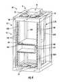
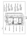
- FIG. 3is a perspective diagram of an example embodiment of a complex system in the form of a telecommunications system cabinet having a number of mateable components that include a cabinet with an equipment rack that holds rack-mountable housings, which in turn house various other types of telecommunications system components;
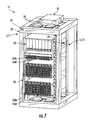
- FIG. 4is a perspective diagram similar to FIG. 3 , illustrating an example embodiment wherein the cabinet includes rail RFID tags arranged along both front vertical rails of the equipment rack to provide RFID tag connection redundancy as well as orientation information of the rack-mountable housing when mounted in the equipment rack;
- FIG. 5Ais a perspective diagram similar to FIG. 3 , illustrating the addition of patch-panel components to the rack-mounted housings, wherein the patch-panel components include patch-panel RFID tags that mate with the corresponding housing RFID tags;
- FIG. 5Bis a close-up front view of an example embodiment of a patch-panel component that includes two patch-panel RFID tags, and wherein each adapter in the patch panel has an associated adapter RFID tag;
- FIG. 5Cis a close-up perspective schematic diagram similar to FIG. 5A , showing in greater detail how the patch-panel RFID tags mate with the housing RFID tags, and how the housing RFID tags mate with the rail RFID tags;
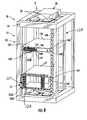
- FIG. 6Ais a perspective diagram similar to FIG. 5A , illustrating the addition to the system of a jumper cable connected to two adapters of different patch panels;
- FIG. 6Bis a close-up side view of the jumper cable and one of its connectors prior to the connector being inserted into an adapter of the patch panel and the jumper RFID tag mating with the adapter RFID tag;
- FIG. 6Cis similar to FIG. 6B , illustrating the jumper cable connector mated with the patch-panel adapter, and the jumper RFID tag mated with the adapter RFID tag, and also showing the subsequent transmission of RFID tag signals from the two RFID tags to the RFID reader;
- FIG. 7is similar to FIG. 6A , and shows the addition to the telecommunications cabinet of another component in the form of rack-mounted electronics;
- FIG. 8is a schematic diagram similar to FIG. 7 , and shows a sample telecommunications cabinet with a single jumper cable joining two adapters on two different patch panels of two different housings;
- FIGS. 9A , 9 B and 9 Cillustrate example embodiments of how individual RFID tags on various system components are provided with unique ID numbers N that include both a product serial number and a physical location in the complex system;
- FIG. 10Ais a schematic close-up side view similar to FIG. 6B , showing the jumper cable connector prior to being connected (mated) to a patch-panel adapter, wherein the adapter has associated therewith four adapter RFID tags arranged on respective sides of the adapter;
- FIG. 10Bis a front-on view of the adapter of FIG. 10A , along with the four associated adapter RFID tags arranged so that a given mating between the jumper RFID tag and one of the adapter RFID tags provides information regarding the orientation of the jumper connector relative to the adapter;
- FIG. 11shows an example of displaying the detected configuration of the example telecommunications system cabinet in the process of being configured.
- a related aspectincludes directing the configuration of the complex system, and in particular the re-configuration of the system.
- a “complex system”means a system having a number of mateable components that, because of their sheer numbers and/or the character of how the components mate, manually tracking the different possible system configurations can be tedious and/or can be relatively difficult and can lead to errors in the system configuration.
- what constitutes a “complex system”is not a function of the number of components per se, but rather is a function of the importance of achieving the proper mating connection among different system components, and the adverse consequences associated with making one or more improper connections.
- a system having just a few mateable componentscan be considered a “complex system” if manually tracking the configuration of the mateable components is problematic due to their location and/or if the adverse consequences to the system are considered severe if the configuration is improper or if the configuration changes due to a component failure or other unintended reason.
- the systems andare described in connection with complex systems based on telecommunications system apparatus.
- Such apparatusincludes components in the form of various types of network equipment, including the associated optical and electrical links in a data center application.
- Each system componente.g., a piece of network equipment such as patch cable connectors, adapters, patch panels and rack-mounted housings, electronics and optical/electrical equipment, etc.
- Each system componentis provided with one or more RFID tags that are able to detect physical mating with RFID tags on other network equipment.
- the RFID tags(which are also referred to in the art as “RFID transponders”) include a switch (e.g., a push-button-type switch) that electrically connects/disconnects and activates/deactivates the RFID antenna so that a person (e.g., a technician) installing components into the complex system can selectively activate the RFID tags during the process.
- the switchprovides a latchable signal to the integrated circuit (IC) as an IC input rather than or in addition to connecting or activating the antenna.
- the techniciancan activate the RFID tag to generate a signal representative of the type of component to which the RFID tag is attached, and where the component is to be connected.
- An example of such an RFID tagis described in U.S.
- the term “component” as used hereinis intended to be widely construed to include, for example, a piece of equipment, device, tool, apparatus, connector, structure, element, constituent, module, part, unit, machinery, gear, etc. that makes up the complex system and that plays a role in determining the complex system configuration.
- some components of the complex systemneed not be considered when detecting the system configuration. What constitutes a component that needs to be considered when detecting the system configuration will depend on the nature of the complex system and the end-user's needs with regard to what constitutes operable and non-operable states of the complex system. For example, in the discussion below, a telecommunications system cabinet is considered, wherein the cabinet has a frame.
- the framecan be considered a “component” because it supports an equipment rack and may be worth identifying as a specific frame amongst a host of such frames in a central office.
- the frame as a componentmay not be considered relevant by the end-user as compared to detecting other components, such as jumper cables, when there is only one frame in a particular closet, for example.
- a “set” of mateable componentsis considered, wherein the set can include some or all of the total number of components that constitute the complex system, as the case may be.
- numbers presented in italicsrepresent identification (ID) numbers N that generally include information having at least one piece of data relating to the component to which it is attached, such as for example, one or more serial numbers, relative locations, orientations, etc.
- ID numbers Nare stored and processed by the RFID configuration detection system in order to detect and communicate (e.g., display) the configuration of the complex system.
- the methods of detecting and/or directing the physical configuration of the complex system using mating RFID tags that exchange information (e.g., in the form of unique component ID numbers N) and that communicate their mating statuscan be used to automatically determine the configuration of any complex system having physically mateable components, and to direct the configuration (including the re-configuration) of the complex system.
- embodimentsinclude configurations wherein one, two, or even more antennas are arranged in each shelf unit and/or wherein each shelf is completely independent of its rack and has one or more readers and one or more antennas associated therewith as needed to establish the configuration-detecting and/or configuration directing functionalities of the present invention as described in detail below.
- FIG. 1is a schematic diagram of an example embodiment of an RFID configuration detection system (“RFID system”) 8 according to embodiments disclosed herein, which is an RFID system capable of automatically detecting and communicating the physical configuration of a complex system.
- RFID system 8also can be used to direct the configuring of the complex system, and in particular, the reconfiguring of the complex system.
- the physical configurationincludes the presence or absence of various parts independent of their connectivity.
- RFID system 8 of some embodimentsmay be configured to serve one or more other functions, such as the function of asset/inventory management, in addition to its configuration detection and configuration directing functions.
- RFID system 8is shown interfaced with an example complex system 10 that includes a set of one or more different types of components 12 .
- the set of components 12include a number (e.g., a subset) of one or more different types of first components 12 A (see, e.g., Inset 1 ) and a number (e.g., a subset) of one or more different types of second components 12 B that are mateable with one, some or all of the first components (see, e.g., Inset 2 ).
- Each first component 12 Ahas associated therewith (e.g., fixed thereto) a first RFID tag 16 A.
- First components 12 Aare all shown schematically as being the same, though in practice a variety of different types of first components are typically included in complex system 10 .
- Each component 12 Ais configured to mate with (e.g., mechanically, electrically or optically connect to) or otherwise be placed in operable relationship with a corresponding second component 12 B that has associated therewith (e.g., fixed thereto) a second RFID tag 16 B.
- RFID tags 16 A and 16 Bare configured to mate (i.e., electrically connect) when first component 12 A mates with or is otherwise arranged in operable relationship to its counterpart second component 12 B.
- components 12 A and/or 12 Bmay be, for example, rack-mountable electronic devices, rack-mountable electrical/optical devices, rack-mountable housings, patch panels, jumper cables, switches, routers, servers, and the like. These components may need to be arranged in the system in a select manner, e.g., a select orientation, and with select connections.
- the terms “first” and “second” componentsare used in the present example for the sake of convenience.
- the various componentscould also include “third” components that mate with the second components, “fourth” components that mate with the third components, etc.
- the inventioncan include embodiments wherein three or more RFID tags may all communicate to each other rather than just two tags in a point-to-point topology, e.g., on a common bus or star configuration, such as shown schematically in some of the components and RFID tags in complex system 10 of FIG. 1 .
- Each RFID tag 16includes a substrate 18 , an IC chip 20 (not shown in FIG. 1 ; see FIGS. 2A and 2B ), an antenna 22 , and electrical contact members 24 .
- Each RFID tag 16is adapted to store information in IC chip 20 . In an example embodiment, this information includes at least one piece of data relating to the RFID tag's 16 associated component 12 .
- Each RFID tag 16is also adapted to mate with an RFID tag of an associated component (via contact members 24 ) and share and store information when the two related components 12 A and 12 B are brought into their operable (or in some cases, an inoperable) configuration in complex system 10 .
- RFID system 8further includes at least one RFID reader 30 that has an RFID antenna system 32 with at least one antenna element 33 .
- RFID reader 30also optionally includes a second antenna system 34 for transmitting wireless data signals SD.
- RFID reader 30and in particular RFID antenna system 32 , is preferably arranged relative to complex system 10 so that it can receive RFID tag signals ST from all of the RFID tags 16 used to monitor the configuration of the complex system. In an example embodiment, this involves strategically arranging a plurality of antenna elements 33 throughout complex system 10 .
- RFID reader 30is configured to switch between antenna elements 33 so that it can selectively interrogate and/or receive RFID tag signals ST from RFID tags 16 located in different regions of complex system 10 .
- multiple RFID readers 30 and multiple antenna elements 33are used to provide RF coverage of complex system 10 .
- RFID system 8further includes an information processing system 40 , such as a computer, operably connected to RFID reader 30 and adapted to store and process information from RFID reader 30 .
- information processing system 40includes a wireless antenna 44 (e.g., a wireless card) that receives wireless data signals SD from RFID reader 30 and that can transmit RF wireless communication signals S 40 to RFID reader 30 (e.g., to elicit the transmission of information from the RFID reader).
- information processing system 40includes a wire (e.g., an Ethernet cable) 46 connected to RFID reader 30 for wired communication with RFID reader 30 via electronic data signals SD and/or electronic communication signals S 40 .
- Information processing system 40can include a database unit 50 adapted (e.g., via database unit software stored on a computer-readable medium) to store and process information, particularly information about RFID tags 16 provided to the information processing system 40 from RFID reader 30 .
- database unit 50includes basic (e.g., background or general) information about complex system 10 , such as its overall structure, the number of components 12 that constitute the system, the different types of components making up the system, orientation information about orientation-sensitive components, etc.
- this basic informationis inputted into database unit 50 (e.g., manually, or via an external computer-readable medium such as a compact disk or so-called “memory stick”) prior to any configuration-status information being received from RFID reader 30 .
- information processing system 40includes a display 60 , such as a standard liquid crystal display (LCD) monitor or personal digital assistant (PDA), to provide two non-limiting examples, that displays (e.g., using graphics and/or alphanumerics) the system configuration information stored in database unit 50 .
- display 60such as a standard liquid crystal display (LCD) monitor or personal digital assistant (PDA), to provide two non-limiting examples, that displays (e.g., using graphics and/or alphanumerics) the system configuration information stored in database unit 50 .
- LCDliquid crystal display
- PDApersonal digital assistant
- the second components 12 Bsuch as for example a second piece of telecommunications network equipment (e.g., a patch panel), being installed into complex system 10 so as to mate with one of the first components 12 A, as illustrated by arrow Al (see also see Inset 2 ).
- This installationmay involve, for example, placing a telecommunications network component into a rack-mounted housing 12 H (not shown in FIG. 1 ; see FIG. 3 ), as illustrated by arrow A 2 , and as discussed in an example embodiment below.
- first component 12 Amates with second component 12 B
- the RFID tag 16 B on second component 12 Belectrically mates with RFID tag 16 A of first component 12 A via respective contact members 24 B and 24 A, as illustrated in Inset 2 .
- RFID tags 16are configured to store information in IC chip 20 , such as ID numbers N, and exchange these numbers with its mated RFID tag. RFID tags 16 are also configured to transmit some or all of this information via a wireless RFID tag signal ST (i.e., RFID tag signals ST A and ST B for RFID tags 16 A and 16 B, respectively) transmitted by antenna 22 .
- RFID reader 30is adapted to transmit RF wireless reader signals SR, which in an example embodiment are used to interrogate (poll) one or more RFID tags 16 .
- reader signals SRare used to write information to one or more RFID tags 16 , or to activate a signaling device 27 , such as a light (e.g., a light emitting diode (LED), on one or more of the RFID tags 16 (see FIG. 2B ).
- RFID reader 30also transmits the pairs of RFID tag ID numbers N (e.g., ID numbers NA and NB for mated RFID tags 16 A and 16 B) for all mated components 12 to information processing system 40 using (wireless and/or wired) data signals SD.
- Database unit 50 within information processing system 40stores and processes the information about complex system 10 .
- database unit 50combines the information received from RFID reader 30 with previously stored basic information about complex system 10 to map all received RFID tag ID numbers N to known component types. Using the pairs of RFID tag ID numbers N, information processing system 40 automatically determines the relative positions (and optionally the component orientation of orientation-sensitive components) of the mated components 12 . As mentioned above, this information can then be displayed on display 60 to provide a user with a (real-time) view of the configuration of complex system 10 .
- information processing system 40automatically indicates which patch panel is attached to which port on a given rack-mounted housing. This information is recorded in database unit 50 without it ever having to be manually entered. In an example embodiment, information processing system 40 also immediately detects when other components 12 (e.g., patch cables, patch panels, housings, switches, routers, and servers in the case of a telecommunications application) are added or removed from complex system 10 (e.g., from any data center cabinets), and automatically updates database unit 50 to reflect any changes in the configuration of complex system 10 . This method leverages the pre-configuration of all RFID tags 16 at manufacture time and also provides a real-time configuration status of complex system 10 .
- components 12e.g., patch cables, patch panels, housings, switches, routers, and servers in the case of a telecommunications application
- a component 12includes more than one RFID tag 16 (e.g., a patch panel with twelve adapters, where each adapter has its own RFID tag)
- a standardized ID number schemeis used for each RFID tag so that its physical position P in complex system 10 (or its position relative to another component) can be determined via its ID number N.
- the RFID tag informationallows the database unit software to determine if the orientation of the installed component is correct.
- FIG. 2Ais a schematic diagram of an example embodiment of two mateable RFID tags 16 A and 16 B according to embodiments disclosed herein, prior to the RFID tags being mated.
- RFID tag substrate 18supports RFID (IC) chip 20 and RFID antenna 22 , which is electrically connected to IC chip 20 .
- IC chip 20is configured to store information, such as the above-mentioned ID number N, which in turn may include one or more pieces of data, such as a serial number, component type, component manufacturer, manufacturing date, installation date, location, lot number, performance parameters (such as attenuation measured during installation), identification of what is at the other end of the component, etc.
- informationis preloaded onto IC chip 20 at manufacture time, or is loaded onto IC chip 20 using RFID reader 30 and reader signals SR.
- contact members 24 Aare “pogo pins” electrically connected to IC chip 20 A, while contact members 24 B are in the form of contact pads or contact slots electrically connected to IC chip 20 B and adapted to mate with contact members 24 A to establish an electrical connection between IC chips 20 A and 20 B, as shown in FIG. 2B .
- Thisallows IC chips 20 A and 20 B to exchange information, such as their respective ID numbers N, as well as a status indicator (e.g., a bit sequence) that indicates that RFID tags 16 A and 16 B are mated.
- this informationis provided to RFID reader 30 in response to subsequent RFID reader polls via reader signals SR.
- This embodimentis preferred when RFID tags 16 require a polling signal from RFID reader 30 to power the IC chip 20 .
- the RFID tags 16automatically transmit this information when they are mated.
- RFID tags 16 A and 16 Bare disconnected, in an example embodiment their disconnected state is saved in their respective IC chips 20 A and 20 B to indicate that they are disconnected from one another.
- This “disconnect” stateis communicated to RFID reader 30 on subsequent RFID reader polls via reader signals SR or is transmitted by the RFID tags 16 at or near the time when the disconnection occurs.
- This disconnect statecan also be displayed using signaling device 27 on one or both of the RFID tags 16 associated with disconnected components 12 .
- FIG. 3is a perspective diagram of an example embodiment of a complex system 10 in the form of a telecommunications system cabinet 12 C.
- Cabinet 12 Cwhich itself is considered a “component,” includes an outer support frame 12 F that supports right and left inner front vertical rails 102 R and 102 L (hereinafter, “right and left front rails”) with respective right and left front faces 103 R and 103 L.
- Support frame 12 Falso supports right and left inner rear vertical rails 104 R and 104 L (hereinafter, “right and left rear rails”), and includes a top panel 108 and a bottom panel 110 .
- Support frame 12 F and top and bottom panels 108 and 110define a frame interior 120 with a front opening 124 .
- support frame 12 Fincludes a frame RFID tag 16 F that includes information about the support frame (e.g., its serial number, its location, its installation date, the types of components it supports, etc.).
- front and rear rails 102 and 104include support brackets (not shown) and define an equipment rack 12 R that supports one or more telecommunications network-related components 12 such as, for example, rack-mountable housings 12 H configured to be stored in a stacked fashion within frame interior 120 .
- each rack-mountable housing 12 Hincludes a front 141 , a top panel 142 , a bottom panel 144 , and right and left side panels 146 R and 146 L that define an open housing interior 148 .
- RFID system 8includes one or more “rail” RFID tags 16 R mounted on front right 102 R (e.g., on front surface 103 R).
- RFID system 8also includes one or more “housing” RFID tags 16 H mounted on each housing 12 H.
- at least one of the housing RFID tags 16 His mounted on one of the housing side panels 146 R or 146 L so as to mate with a corresponding rail RFID tag 16 R when housing 12 H is supported within equipment rack 12 R of cabinet 12 C.
- Other housing RFID tags 16 Hare shown arranged on housing top panel 142 as well as within housing interior 148 for mating with RFID tags on individual patch panels, as discussed below.
- all rail RFID tags 16 R in RFID system 8are programmed at the time of manufacture with the aforementioned unique ID numbers N.
- ID numbers Nindicate, for example, both a serial number N for the component and the relative position P of the component RFID tag.
- ID numbers NR for rail RFID tags 16 Rindicate each RFID tag's 16 R relative position along front rail 102 R. This also allows each rail 102 to be automatically associated with a cabinet ID number N C of the cabinet 12 C (or frame ID number N F of the frame 12 F) in which it is installed.
- all housing RFID tags 16 Hare programmed at the time of manufacture with unique identification numbers N H that indicate both the housing serial number and the position of the RFID tag P H on the housing (e.g., its relative location along the top panel 142 ).
- At least one RFID reader 30is included within, on or near cabinet 12 C.
- RFID reader 30is mounted on frame top panel 108 (as illustrated in FIG. 3 ) or on frame bottom panel 110 .
- RFID reader antenna system 32is preferably arranged to optimize RFID tag communication.
- antenna system 32includes two or more antenna elements 33 arranged in different locations within, on or around cabinet 12 C to ensure that RFID reader 30 can read RFID tag signals ST from all RFID tags 16 of RFID system 8 associated with the complex system 10 defined by cabinet 12 C, and to transmit RFID reader signals SR to one or more of the RFID tags.
- RFID reader 30is configured to switch between antenna elements 33 so that it can selectively interrogate RFID tags 16 with RFID signals SR and/or receive RFID tag signals ST from RFID tags 16 located within different regions of cabinet 12 C.
- An example embodiment of RFID system 8provides various RFID tags 16 arranged such that if a given component 12 of complex system 10 is not installed in its proper orientation, the corresponding RFID tags 16 cannot mate. For example, with reference to FIG. 3 , if housing 12 H were mounted upside down in cabinet 12 C, the corresponding rail RFID tags 16 R and the housing RFID tags 16 H would not mate because there are no rail RFID tags on left front vertical rail 102 L. Failure to generate at least one RFID tag signal ST upon installing housing 12 H would indicate an incorrect housing orientation and thus an incorrect configuration for cabinet 12 C.
- rail RFID tags 16 Rare provided on both right and left front vertical rails 102 R and 102 L.
- the corresponding rail RFID tags 16 R and housing RFID tags 16 Hmate when the housing is added to equipment rack 12 R, but each housing RFID tag 16 H is programmed to indicate if it is on the top or bottom of the particular housing.
- the redundant rail RFID tags 16 Rprovide information about the installation of housing 12 H even with the failure of one of the rail RFID tags, or if there is tag-mating failure on one end of the housing. In an example embodiment, this same redundancy method is applied to some or all of the other components, such as the modules within the housing, or even adapters within the modules.
- both RFID tags 16respond with respective RFID tag signals ST that include the identification number of their mating RFID tag 16 (see e.g., FIG. 1 ) and optionally a status indicator (e.g., a bit sequence) that indicates that RFID tags 16 H and 16 R are mated.
- a status indicatore.g., a bit sequence
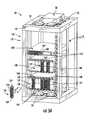
- FIG. 5Ais a schematic diagram similar to FIG. 3 , but showing the insertion of patch panels 12 P in rack-mounted housings 12 H that are already installed within equipment rack 12 R of cabinet 12 C.
- Patch panels 12 Pinclude at least one patch-panel RFID tag 16 P.
- Patch panel 12 Pincludes an array of adapters 12 A, with each adapter having associated therewith an adapter RFID tag 16 A, as illustrated in the close-up front-on view of patch panel 12 P of FIG. 5B .
- FIG. 5Cis a close-up schematic diagram similar to FIG. 5A , showing more details of how patch-panel RFID tags 16 P mate with the corresponding housing RFID tags 16 H, and how rail RFID tags 16 R on right front vertical rail 102 R mate with the corresponding housing RFID tags 16 H.
- adapters 12 Aare omitted for ease of illustration.
- Housing 12 H in FIG. 5Cis shown as having a top front flange 147 and two side front flanges 149 that facilitate mounting the housing in equipment rack 12 R.
- Top front flange 147includes a number housing RFID tags 16 H (three such RFID tags are shown).
- Right-side front flange 149includes another housing RFID tag 16 H.
- housing 12 Hmay include additional housing RFID tags 16 H on a bottom panel 144 to provide a way to detect whether the orientation of the inserted patch panel is incorrect (i.e., installed upside-down).
- FIG. 6Ais a schematic diagram of RFID system 8 and complex system 10 similar to that shown in FIG. 5A , illustrating the addition to cabinet 12 C of another component in the form of a patch cable (or “jumper” cable) 12 J that enables a communication link between two adapters 12 A on two separate patch panels 12 P.
- Jumper cable 12 Jincludes a cable section 231 and connectors 232 A and 232 B at the cable's opposite ends.
- each connector 232 A and 232 B of jumper cable 12 Jrespectively includes a jumper RFID tag 16 JA and 16 JB integrated therewith or otherwise fixed thereto, as shown in the close-up side view of the jumper cable and adapter array 230 of FIG. 6B .
- jumper RFID tags 16 Jare programmed at the time of manufacture with a unique identification number N J that indicates both the jumper cable serial number and the specific connector type used on the jumper cable.
- jumper connector 232 Awhen jumper connector 232 A is installed in a patch panel adapter 12 A, its jumper RFID tag 16 JA automatically mates with the corresponding adapter RFID tag 16 A of patch panel 12 P.
- RFID reader signal SRfrom RFID reader 30
- one or both RFID tagsrespond with transmitting respective RFID tag signals ST (i.e., ST JA and/or ST A ) that include the ID number N of their mating RFID tag.
- only one of the mated RFID tags( 16 JA or 16 A) transmits a RFID tag signal ST that includes both ID numbers N J and N A and optionally a status indicator (e.g., a bit sequence) that indicates that RFID tags 16 JA and 16 A are mated.
- a status indicatore.g., a bit sequence
- FIG. 7is similar to the view of RFID system 8 and cabinet 12 C of FIG. 6A , and shows the addition to equipment rack 12 R of another rack-mounted component in the form of rack-mounted electronics 12 E.
- rack-mounted electronics 12 Eincludes an electronics RFID tag 16 E configured to mate with a corresponding rail RFID tag 16 R on right front face 103 R of right front vertical rail 102 R.
- electronics RFID tag 16 Eis programmed at the time of manufacture with a unique identification number N E that can be used to determine features of rack-mounted electronics 12 E using the database unit software, which in an example embodiment relating to a telecommunications system includes network management software.
- the mated RFID tags 16 E and 16 Rare polled by a signal SR from the RFID reader antenna, in an example they each respond by transmitting respective RFID tag signals ST (i.e., ST E and ST C ) that include the ID number N C and N E of their mating RFID tag, and optionally a status indicator (e.g., a bit sequence) that indicates that RFID tags 16 E and 16 R are mated.
- RFID tag signals STi.e., ST E and ST C
- a status indicatore.g., a bit sequence
- FIG. 8is a schematic diagram similar to FIG. 5A , showing a sample cabinet 12 C wherein a single jumper cable 12 J joins two adapters 12 A on two different patch panels 12 P in two different housings 12 H.
- Each component 12includes one or more RFID tags 16 with a unique ID number N.
- FIGS. 9A , 9 B and 9 Cillustrate an example embodiment of how individual RFID tags 16 on various system components 12 of complex system 10 of FIG. 8 have unique ID numbers N that include, for example, a product serial number and a physical location of the RFID tag 16 in complex system 10 .
- the ID numbers N for the various components 12are shown in italics. In cases where a particular ID number N is not explicitly shown, it can be inferred from neighboring labeled RFID tags.
- FIG. 10Ais a schematic side view of connector 232 A of jumper cable 12 J being connected to an adapter 12 A of patch panel 12 P, wherein the adapter 12 A includes four adapter RFID tags 16 A arranged on respective sides of the adapter 12 A.
- FIG. 10Bis a front-on view of adapter 12 A and the four associated adapter RFID tags 16 A.
- Adapter RFID tags 16 Ainclude information about their respective positions relative to adapter 12 A (i.e., top, bottom, left side, right side).
- the arrangement of adapter RFID tags 16 Aallows for one of the four adapter RFID tags 16 A to mate with the jumper RFID tag 16 JA.
- FIG. 10A and FIG. 10Bit is assumed that four different orientations are possible.
- the arrangement of RFID tags 16 in FIG. 10A and FIG. 10B to establish orientationinvolves two or more RFID tags 16 . This method allows for RFID system 8 to detect whether a given component—here, jumper cable 12 J—is correctly installed in complex system 10 .
- database unit 50(or signaling device 27 ) flags the improper connect condition and in an example embodiment, conspicuously indicates the improper connect condition so that an end-user can immediately spot the incorrect connection and take corrective action (e.g., insert connector 232 A into adapter 12 A in its proper orientation).
- RFID system 8facilitates configuring a complex system such as complex system 10 .
- the component configuration informationis provided to an end-user of complex system 10 (or an end-user of RFID system 8 , as the case may be).
- information about the component configuration of complex system 10is displayed on display 60 of information processing system 40 .
- information processing system 40includes a graphics driver and uses graphics to display a representation of complex system 10 on display 60 .
- FIG. 11shows an example display 60 that displays graphic and/or alphanumeric information about the configuration of the above-described example complex system 10 in the form of telecommunications cabinet 12 C.
- Display 60shows the various network-related components 12 C and a list of mated RFID tags 16 obtained by RFID tag reader 30 .
- the information shown on display 60is provided by database unit 50 and is based on ID number information provided by RFID reader 30 and so is presented in italics in FIG. 11 for the sake of illustration.
- the physical configuration, and hence the physical location, of each component 12 in complex system 10can be inferred from the complete set of neighboring labeled RFID tags that are found to be mated to each other.
- An example of providing a progressive summary of the evolving configuration of complex system 10 as based on individual mated RFID tag data of the type that might be communicated via display 60 of information processing system 40 via the operation of the network management software operating in database unit 50is as follows:
- the configuration of any component 12 in complex system 10can be determined. For example, it is possible to determine how a specific jumper cable 12 J is configured, and this information may be displayed on display 60 as follows:
- This particular telecommunication-based exampleutilizes a method that incorporates detection of a jumper cable to adapters, adapter attachment in patch panels, patch panel attachment to housings, and housing attachment to cabinets. While this hierarchical approach is well-suited for many communications network equipment applications, including data center management, there are other applications where a non-hierarchical interconnection of mating RFID tags is desirable. For example, consider determining the physical configuration of a two-dimensional array of components. RFID tags can be positioned on the four sides of each component, and arranged to mate with corresponding tags on neighboring components. In addition, similar approaches could be used in applications other than communications network equipment applications. For example, similar approaches could be used to assure proper assembly of complex mechanical, electrical, and optical structures, as well as complex structures that employ combinations of electrical, mechanical and optical components.
- RFID tags 16can include switches that allow for the RFID tag 16 to transmit information to RFID reader 30 about the component 12 to which the particular RFID tag 16 is attached.
- the methodincludes actively managing the configuration of complex system 10 as the complex system 10 is being configured, for example, by an on-site technician.
- This methodincludes, for example, activating the RFID tag 16 for a given component (for example, a component 12 A of FIG. 1 ) prior to mating the component 12 with another component (for example, a component 12 B of FIG. 1 ).
- the RFID reader 30receives this RFID tag signal and consults information processing system 40 , which tells the RFID reader 30 to which component 12 B the component 12 A is supposed to be mated.
- RFID reader 30then transmits a signal to the corresponding RFID tag 16 B, which in an example embodiment includes signaling device 27 , such as a light, which is activated by the RFID reader signals via IC chip 20 . This shows the technician to which component 12 B the component 12 A in hand is to be connected.
- signaling device 27such as a light
- RFID tags 16 A and 16 Btransmitting the other tags ID number N to RFID reader 30 , which information is then transmitted to information processing system 40 . If the particular components 12 A and 12 B are not supposed to be connected, then information processing system 40 sends a signal to RFID reader 30 that indicates an incorrect connection. RFID reader 30 then sends a signal to one or both RFID tags 16 A and 16 B to cause signaling device(s) 27 to be activated in a manner that indicates a connection error (e.g., blinking red lights).
- a connection errore.g., blinking red lights
- Embodiments of the present inventionhave a number of advantages, particularly relating to the application to complex telecommunications systems.
- the same method for detecting installed network componentscan be applied to all types of data center network equipment, including components from different companies and manufacturers.
- the ability to automatically monitor the configuration of a complex telecommunications systemcan be used to help guide the system installers to achieve the proper system configuration in less time and with fewer errors in the final system.
- the database unit softwareincludes network management software adapted to determine the current (i.e., real-time) physical configuration of a data center network using information from mated RFID tag pairs on network equipment.
- the system configurationcan be constantly updated as changes are made to the system, such as components being mated (connected) and unmated (disconnected). This eliminates the need to manually record and enter physical location data on network equipment into network management software both during system set-up as well as during system maintenance or when changing the system configuration for any reason. It also ensures that the network management software database is completely accurate, even while new network equipment is being added or removed.
- the RFID configuration detection systemcan be set up to track the correct orientation of orientation-sensitive components and can be configured to provide detection redundancy should one of the RFID tags fail or should two tags fail to properly mate.
Landscapes
- Engineering & Computer Science (AREA)
- Computer Hardware Design (AREA)
- Microelectronics & Electronic Packaging (AREA)
- Physics & Mathematics (AREA)
- General Physics & Mathematics (AREA)
- Theoretical Computer Science (AREA)
- General Engineering & Computer Science (AREA)
- Computer Networks & Wireless Communication (AREA)
- Near-Field Transmission Systems (AREA)
Abstract
Description
- Housing21 is mounted in
Cabinet 1, Rack position6.
21-1←→4301-0 Patch panel 301 is mounted in Housing21,Patch panel position 1, inCabinet 1, Rack position6.
301-7←→4001-1Jumper 4001Connector 1 is mounted inPatch panel 301, Adapter position7, in Housing21,Patch panel position 1, inCabinet 1, Rack position6.
1-14←→22-0Housing 22 is mounted inCabinet 1, Rack position14
22-1←→302-0Patch panel 302 is mounted inHousing 22,Patch panel position 1, inCabinet 1, Rack position14.
302-6←→4001-2Jumper 4001Connector 2 is mounted inPatch panel 302, Adapter position6, inHousing 22,Patch panel position 1, inCabinet 1, Rack position14.
- Housing21 is mounted in
Patch panel 301, Adapter position7, in Housing21,Patch panel position 1, inCabinet 1, Rack position6- with
Patch panel 302, Adapter position6, inHousing 22,Patch panel position 1, inCabinet 1, Rack position14.
Claims (20)
Priority Applications (1)
| Application Number | Priority Date | Filing Date | Title |
|---|---|---|---|
| US12/354,335US8138925B2 (en) | 2008-01-15 | 2009-01-15 | RFID systems and methods for automatically detecting and/or directing the physical configuration of a complex system |
Applications Claiming Priority (2)
| Application Number | Priority Date | Filing Date | Title |
|---|---|---|---|
| US1119408P | 2008-01-15 | 2008-01-15 | |
| US12/354,335US8138925B2 (en) | 2008-01-15 | 2009-01-15 | RFID systems and methods for automatically detecting and/or directing the physical configuration of a complex system |
Publications (2)
| Publication Number | Publication Date |
|---|---|
| US20090195363A1 US20090195363A1 (en) | 2009-08-06 |
| US8138925B2true US8138925B2 (en) | 2012-03-20 |
Family
ID=40445296
Family Applications (1)
| Application Number | Title | Priority Date | Filing Date |
|---|---|---|---|
| US12/354,335Active2030-06-04US8138925B2 (en) | 2008-01-15 | 2009-01-15 | RFID systems and methods for automatically detecting and/or directing the physical configuration of a complex system |
Country Status (6)
| Country | Link |
|---|---|
| US (1) | US8138925B2 (en) |
| EP (1) | EP2235660B1 (en) |
| JP (1) | JP2011510402A (en) |
| CN (1) | CN101952836B (en) |
| CA (1) | CA2712072A1 (en) |
| WO (1) | WO2009091888A1 (en) |
Cited By (91)
| Publication number | Priority date | Publication date | Assignee | Title |
|---|---|---|---|---|
| US20050182306A1 (en)* | 2004-02-17 | 2005-08-18 | Therasense, Inc. | Method and system for providing data communication in continuous glucose monitoring and management system |
| US20080286316A1 (en)* | 2007-05-18 | 2008-11-20 | Heidi Kay | Lipid raft, caveolin protein, and caveolar function modulation compounds and associated synthetic and therapeutic methods |
| US20080319295A1 (en)* | 2007-06-21 | 2008-12-25 | Abbott Diabetes Care, Inc. | Health management devices and methods |
| US20080319296A1 (en)* | 2007-06-21 | 2008-12-25 | Abbott Diabetes Care, Inc. | Health monitor |
| US20100082266A1 (en)* | 2003-04-04 | 2010-04-01 | Abbott Diabetes Care Inc. | Method and System for Transferring Analyte Test Data |
| US20100171610A1 (en)* | 2003-04-28 | 2010-07-08 | Abbott Diabetes Care Inc. | Method and Apparatus for Providing Peak Detection Circuitry for Data Communication Systems |
| US20100235439A1 (en)* | 2003-07-15 | 2010-09-16 | Abbott Diabetes Care Inc. | Glucose Measuring Device Integrated Into A Holster For A Personal Area Network Device |
| US20110044333A1 (en)* | 2008-05-30 | 2011-02-24 | Abbott Diabetes Care Inc. | Close Proximity Communication Device and Methods |
| US20110054282A1 (en)* | 2009-08-31 | 2011-03-03 | Abbott Diabetes Care Inc. | Analyte Monitoring System and Methods for Managing Power and Noise |
| US20110184268A1 (en)* | 2010-01-22 | 2011-07-28 | Abbott Diabetes Care Inc. | Method, Device and System for Providing Analyte Sensor Calibration |
| US20110224525A1 (en)* | 2005-10-31 | 2011-09-15 | Abbott Diabetes Care Inc. | Method and Apparatus for Providing Data Communication in Data Monitoring and Management Systems |
| US20130076589A1 (en)* | 2011-09-26 | 2013-03-28 | Punduit Corp. | Rfid patch cord identification and signaling |
| US8444560B2 (en) | 2007-05-14 | 2013-05-21 | Abbott Diabetes Care Inc. | Method and apparatus for providing data processing and control in a medical communication system |
| US8456301B2 (en) | 2007-05-08 | 2013-06-04 | Abbott Diabetes Care Inc. | Analyte monitoring system and methods |
| US8461985B2 (en) | 2007-05-08 | 2013-06-11 | Abbott Diabetes Care Inc. | Analyte monitoring system and methods |
| US8471714B2 (en) | 2005-05-17 | 2013-06-25 | Abbott Diabetes Care Inc. | Method and system for providing data management in data monitoring system |
| US20130188966A1 (en)* | 2012-01-19 | 2013-07-25 | Huawei Technologies Co., Ltd. | Optical device, and system and method for managing optical device |
| US8543183B2 (en) | 2006-03-31 | 2013-09-24 | Abbott Diabetes Care Inc. | Analyte monitoring and management system and methods therefor |
| US8542122B2 (en) | 2005-02-08 | 2013-09-24 | Abbott Diabetes Care Inc. | Glucose measurement device and methods using RFID |
| US8560038B2 (en) | 2007-05-14 | 2013-10-15 | Abbott Diabetes Care Inc. | Method and apparatus for providing data processing and control in a medical communication system |
| US8571808B2 (en) | 2007-05-14 | 2013-10-29 | Abbott Diabetes Care Inc. | Method and apparatus for providing data processing and control in a medical communication system |
| US8593287B2 (en) | 2007-05-08 | 2013-11-26 | Abbott Diabetes Care Inc. | Analyte monitoring system and methods |
| US8593109B2 (en) | 2006-03-31 | 2013-11-26 | Abbott Diabetes Care Inc. | Method and system for powering an electronic device |
| US8600681B2 (en) | 2007-05-14 | 2013-12-03 | Abbott Diabetes Care Inc. | Method and apparatus for providing data processing and control in a medical communication system |
| US8612163B2 (en) | 2007-05-14 | 2013-12-17 | Abbott Diabetes Care Inc. | Method and apparatus for providing data processing and control in a medical communication system |
| US8635046B2 (en) | 2010-06-23 | 2014-01-21 | Abbott Diabetes Care Inc. | Method and system for evaluating analyte sensor response characteristics |
| US8682615B2 (en) | 2007-05-14 | 2014-03-25 | Abbott Diabetes Care Inc. | Method and apparatus for providing data processing and control in a medical communication system |
| WO2014060416A1 (en)* | 2012-10-15 | 2014-04-24 | Tyco Electronics Raychem Bvba | Telecommunications fiber optic adapter identification system and method |
| US8710993B2 (en) | 2011-11-23 | 2014-04-29 | Abbott Diabetes Care Inc. | Mitigating single point failure of devices in an analyte monitoring system and methods thereof |
| US8834366B2 (en) | 2007-07-31 | 2014-09-16 | Abbott Diabetes Care Inc. | Method and apparatus for providing analyte sensor calibration |
| US8991690B2 (en) | 2012-11-16 | 2015-03-31 | Tyco Electronics Uk Ltd. | System and method for providing power and communication link for RFID managed connectivity using removable module |
| US9008743B2 (en) | 2007-04-14 | 2015-04-14 | Abbott Diabetes Care Inc. | Method and apparatus for providing data processing and control in medical communication system |
| US9069536B2 (en) | 2011-10-31 | 2015-06-30 | Abbott Diabetes Care Inc. | Electronic devices having integrated reset systems and methods thereof |
| US9088452B2 (en) | 2009-04-29 | 2015-07-21 | Abbott Diabetes Care Inc. | Method and system for providing data communication in continuous glucose monitoring and management system |
| US9095290B2 (en) | 2007-03-01 | 2015-08-04 | Abbott Diabetes Care Inc. | Method and apparatus for providing rolling data in communication systems |
| US9111249B2 (en) | 2012-02-14 | 2015-08-18 | Tyco Electronics Uk Ltd | Physical layer management (PLM) system for use with an optical distribution frame using RFID antennas with localized fields |
| US9125548B2 (en) | 2007-05-14 | 2015-09-08 | Abbott Diabetes Care Inc. | Method and apparatus for providing data processing and control in a medical communication system |
| US9204827B2 (en) | 2007-04-14 | 2015-12-08 | Abbott Diabetes Care Inc. | Method and apparatus for providing data processing and control in medical communication system |
| US9226701B2 (en) | 2009-04-28 | 2016-01-05 | Abbott Diabetes Care Inc. | Error detection in critical repeating data in a wireless sensor system |
| US9317656B2 (en) | 2011-11-23 | 2016-04-19 | Abbott Diabetes Care Inc. | Compatibility mechanisms for devices in a continuous analyte monitoring system and methods thereof |
| US9407510B2 (en) | 2013-09-04 | 2016-08-02 | Commscope Technologies Llc | Physical layer system with support for multiple active work orders and/or multiple active technicians |
| US9474475B1 (en) | 2013-03-15 | 2016-10-25 | Abbott Diabetes Care Inc. | Multi-rate analyte sensor data collection with sample rate configurable signal processing |
| US9474848B2 (en) | 2009-03-09 | 2016-10-25 | Thermedx, Llc | Fluid management system |
| US9532737B2 (en) | 2011-02-28 | 2017-01-03 | Abbott Diabetes Care Inc. | Devices, systems, and methods associated with analyte monitoring devices and devices incorporating the same |
| US9574914B2 (en) | 2007-05-08 | 2017-02-21 | Abbott Diabetes Care Inc. | Method and device for determining elapsed sensor life |
| US9615780B2 (en) | 2007-04-14 | 2017-04-11 | Abbott Diabetes Care Inc. | Method and apparatus for providing data processing and control in medical communication system |
| US9622691B2 (en) | 2011-10-31 | 2017-04-18 | Abbott Diabetes Care Inc. | Model based variable risk false glucose threshold alarm prevention mechanism |
| US9662056B2 (en) | 2008-09-30 | 2017-05-30 | Abbott Diabetes Care Inc. | Optimizing analyte sensor calibration |
| US9750444B2 (en) | 2009-09-30 | 2017-09-05 | Abbott Diabetes Care Inc. | Interconnect for on-body analyte monitoring device |
| US9756404B2 (en) | 2014-07-03 | 2017-09-05 | Fiber Mountain, Inc. | Data center path switch with improved path interconnection architecture |
| US9770541B2 (en) | 2014-05-15 | 2017-09-26 | Thermedx, Llc | Fluid management system with pass-through fluid volume measurement |
| US9907492B2 (en) | 2012-09-26 | 2018-03-06 | Abbott Diabetes Care Inc. | Method and apparatus for improving lag correction during in vivo measurement of analyte concentration with analyte concentration variability and range data |
| US9913600B2 (en) | 2007-06-29 | 2018-03-13 | Abbott Diabetes Care Inc. | Analyte monitoring and management device and method to analyze the frequency of user interaction with the device |
| US9936910B2 (en) | 2009-07-31 | 2018-04-10 | Abbott Diabetes Care Inc. | Method and apparatus for providing analyte monitoring and therapy management system accuracy |
| US9962091B2 (en) | 2002-12-31 | 2018-05-08 | Abbott Diabetes Care Inc. | Continuous glucose monitoring system and methods of use |
| US9968306B2 (en) | 2012-09-17 | 2018-05-15 | Abbott Diabetes Care Inc. | Methods and apparatuses for providing adverse condition notification with enhanced wireless communication range in analyte monitoring systems |
| US9980669B2 (en) | 2011-11-07 | 2018-05-29 | Abbott Diabetes Care Inc. | Analyte monitoring device and methods |
| US9989724B2 (en) | 2014-09-29 | 2018-06-05 | Fiber Mountain, Inc. | Data center network |
| US9995883B2 (en)* | 2014-03-26 | 2018-06-12 | Commscope Technologies Llc | Optical adapter module with managed connectivity |
| US10002233B2 (en) | 2007-05-14 | 2018-06-19 | Abbott Diabetes Care Inc. | Method and apparatus for providing data processing and control in a medical communication system |
| US10022499B2 (en) | 2007-02-15 | 2018-07-17 | Abbott Diabetes Care Inc. | Device and method for automatic data acquisition and/or detection |
| US10025960B1 (en) | 2016-06-29 | 2018-07-17 | The United States of America, as represented by the Administrator of the National Aeronautics and Space Administraion | Frequency multiplexed radio frequency identification |
| US10076285B2 (en) | 2013-03-15 | 2018-09-18 | Abbott Diabetes Care Inc. | Sensor fault detection using analyte sensor data pattern comparison |
| US10111608B2 (en) | 2007-04-14 | 2018-10-30 | Abbott Diabetes Care Inc. | Method and apparatus for providing data processing and control in medical communication system |
| US10116558B2 (en) | 2014-01-24 | 2018-10-30 | Fiber Mountain, Inc. | Packet switch using physical layer fiber pathways |
| US10132793B2 (en) | 2012-08-30 | 2018-11-20 | Abbott Diabetes Care Inc. | Dropout detection in continuous analyte monitoring data during data excursions |
| US10136845B2 (en) | 2011-02-28 | 2018-11-27 | Abbott Diabetes Care Inc. | Devices, systems, and methods associated with analyte monitoring devices and devices incorporating the same |
| US10136816B2 (en) | 2009-08-31 | 2018-11-27 | Abbott Diabetes Care Inc. | Medical devices and methods |
| US10159433B2 (en) | 2006-02-28 | 2018-12-25 | Abbott Diabetes Care Inc. | Analyte sensor transmitter unit configuration for a data monitoring and management system |
| US10225628B2 (en) | 2016-09-14 | 2019-03-05 | Fiber Mountain, Inc. | Intelligent fiber port management |
| US10277496B2 (en) | 2014-03-28 | 2019-04-30 | Fiber Mountain, Inc. | Built in alternate links within a switch |
| US10382845B2 (en) | 2014-09-29 | 2019-08-13 | Fiber Mountain, Inc. | System for increasing fiber port density in data center applications |
| US10433773B1 (en) | 2013-03-15 | 2019-10-08 | Abbott Diabetes Care Inc. | Noise rejection methods and apparatus for sparsely sampled analyte sensor data |
| US10713451B2 (en) | 2015-07-31 | 2020-07-14 | Hewlett Packard Enterprise Development Lp | Optical jumper |
| US10963417B2 (en) | 2004-06-04 | 2021-03-30 | Abbott Diabetes Care Inc. | Systems and methods for managing diabetes care data |
| US11006871B2 (en) | 2009-02-03 | 2021-05-18 | Abbott Diabetes Care Inc. | Analyte sensor and apparatus for insertion of the sensor |
| US11113642B2 (en) | 2012-09-27 | 2021-09-07 | Commscope Connectivity Uk Limited | Mobile application for assisting a technician in carrying out an electronic work order |
| US11213226B2 (en) | 2010-10-07 | 2022-01-04 | Abbott Diabetes Care Inc. | Analyte monitoring devices and methods |
| EP3961522A1 (en)* | 2020-08-24 | 2022-03-02 | Bull SAS | Device identification system and process in a datacenter |
| US11295135B2 (en)* | 2020-05-29 | 2022-04-05 | Corning Research & Development Corporation | Asset tracking of communication equipment via mixed reality based labeling |
| US11374808B2 (en) | 2020-05-29 | 2022-06-28 | Corning Research & Development Corporation | Automated logging of patching operations via mixed reality based labeling |
| US11553883B2 (en) | 2015-07-10 | 2023-01-17 | Abbott Diabetes Care Inc. | System, device and method of dynamic glucose profile response to physiological parameters |
| US11596330B2 (en) | 2017-03-21 | 2023-03-07 | Abbott Diabetes Care Inc. | Methods, devices and system for providing diabetic condition diagnosis and therapy |
| US11717225B2 (en) | 2014-03-30 | 2023-08-08 | Abbott Diabetes Care Inc. | Method and apparatus for determining meal start and peak events in analyte monitoring systems |
| US11793936B2 (en) | 2009-05-29 | 2023-10-24 | Abbott Diabetes Care Inc. | Medical device antenna systems having external antenna configurations |
| US11857776B2 (en) | 2019-11-08 | 2024-01-02 | Stryker Corporation | Fluid management systems and methods |
| US12239463B2 (en) | 2020-08-31 | 2025-03-04 | Abbott Diabetes Care Inc. | Systems, devices, and methods for analyte sensor insertion |
| US12268496B2 (en) | 2017-01-23 | 2025-04-08 | Abbott Diabetes Care Inc. | Systems, devices and methods for analyte sensor insertion |
| US12274548B2 (en) | 2006-10-23 | 2025-04-15 | Abbott Diabetes Care Inc. | Sensor insertion devices and methods of use |
| US12279866B2 (en) | 2012-10-30 | 2025-04-22 | Abbott Diabetes Care Inc. | Sensitivity calibration of in vivo sensors used to measure analyte concentration |
| US12290354B2 (en) | 2011-06-16 | 2025-05-06 | Abbott Diabetes Care Inc. | Temperature-compensated analyte monitoring devices, systems, and methods thereof |
Families Citing this family (48)
| Publication number | Priority date | Publication date | Assignee | Title |
|---|---|---|---|---|
| AU2003268119A1 (en)* | 2002-08-21 | 2004-03-11 | Neuroptics, Inc. | Intelligent patient interface for ophthalmic instruments |
| US9652708B2 (en) | 2006-10-31 | 2017-05-16 | Fiber Mountain, Inc. | Protocol for communications between a radio frequency identification (RFID) tag and a connected device, and related systems and methods |
| US9652707B2 (en) | 2006-10-31 | 2017-05-16 | Fiber Mountain, Inc. | Radio frequency identification (RFID) connected tag communications protocol and related systems and methods |
| US9652709B2 (en) | 2006-10-31 | 2017-05-16 | Fiber Mountain, Inc. | Communications between multiple radio frequency identification (RFID) connected tags and one or more devices, and related systems and methods |
| US8421626B2 (en) | 2006-10-31 | 2013-04-16 | Corning Cable Systems, Llc | Radio frequency identification transponder for communicating condition of a component |
| DE102007015111B4 (en)* | 2007-03-29 | 2010-01-07 | Festo Ag & Co. Kg | Sensor device for a fluid power device |
| EP2109059B1 (en)* | 2008-04-09 | 2017-05-17 | Cavea Identification GmbH | Container for receiving articles |
| DE102009009641B4 (en) | 2009-02-19 | 2015-01-08 | Rittal Gmbh & Co. Kg | Control cabinet or rack |
| WO2011015212A1 (en)* | 2009-08-05 | 2011-02-10 | Dieter Kilian | Receiving device with rfid detection of built-in components held therein, and rfid detection method |
| US20110047188A1 (en)* | 2009-08-24 | 2011-02-24 | Carios Martins | Method and System for Automatic Tracking of Information Technology Components and Corresponding Power Outlets in a Data Center |
| EP2507746B1 (en)* | 2009-11-30 | 2015-10-14 | Corning Incorporated | Rfid condition latching |
| US20110173315A1 (en)* | 2010-01-11 | 2011-07-14 | Jerry Aguren | Network physical layer security |
| US8693865B2 (en)* | 2010-01-11 | 2014-04-08 | Hewlett-Packard Development Company, L.P. | Network security using optical attenuation data |
| JP5585110B2 (en) | 2010-02-15 | 2014-09-10 | 日本電気株式会社 | Rack mounting position management system and rack mounting position management method |
| US8172468B2 (en) | 2010-05-06 | 2012-05-08 | Corning Incorporated | Radio frequency identification (RFID) in communication connections, including fiber optic components |
| DE102010019944B4 (en)* | 2010-05-08 | 2012-02-16 | Data Speed Control Gmbh | switch cabinet |
| CN102339414B (en)* | 2010-07-14 | 2014-05-28 | 数伦计算机技术(上海)有限公司 | Security system based on RFID (Radio Frequency Identification Device) |
| CN102542708A (en)* | 2010-12-21 | 2012-07-04 | 数伦计算机技术(上海)有限公司 | Security method based on radio frequency identification (RFID) |
| DE102011017386A1 (en)* | 2011-03-30 | 2012-10-04 | Fujitsu Technology Solutions Intellectual Property Gmbh | Subrack, server and arrangement with such a rack and at least one server |
| US9064022B2 (en) | 2011-05-17 | 2015-06-23 | Adc Telecommunications, Inc. | Component identification and tracking system for telecommunication networks |
| CN102324010A (en)* | 2011-05-18 | 2012-01-18 | 中国科学院长春光学精密机械与物理研究所 | An information automatic identification system for optical detection etalon |
| WO2013095414A1 (en)* | 2011-12-21 | 2013-06-27 | Hewlett-Packard Development Company, L.P. | Proper installation determination based on rfid |
| EP2810449B1 (en)* | 2012-02-01 | 2018-10-03 | Corning Incorporated | Radio frequency identification (rfid) connected tag communications protocol and related systems and methods |
| WO2013116417A1 (en)* | 2012-02-01 | 2013-08-08 | Corning Incorporated | Protocol for communications between a radio frequency identification (rfid) tag and a connected device, and related systems and methods |
| US20130241699A1 (en)* | 2012-03-19 | 2013-09-19 | Redwood Systems, Inc. | Device tracking with lighting system |
| US9165232B2 (en) | 2012-05-14 | 2015-10-20 | Corning Incorporated | Radio-frequency identification (RFID) tag-to-tag autoconnect discovery, and related methods, circuits, and systems |
| ITRM20120222A1 (en)* | 2012-05-16 | 2013-11-17 | Out Line S R L | NEW CONNECTOR FOR OPTICAL FIBER CABLES. |
| CN102708352B (en)* | 2012-06-07 | 2015-02-18 | 南京普天通信股份有限公司 | Method for managing optical fiber jumpers and optical fiber ports by applying pairing two-dimensional code labels |
| US8948740B2 (en)* | 2012-06-08 | 2015-02-03 | Futurewei Technologies, Inc. | Mobile terminal for small cell configuration and maintenance |
| DE102013207755A1 (en)* | 2013-04-29 | 2014-10-30 | Phoenix Contact Gmbh & Co. Kg | Electrical interface module |
| DE102013207760B4 (en) | 2013-04-29 | 2024-02-22 | Phoenix Contact Gmbh & Co. Kg | Electrical interface module |
| US9571904B2 (en)* | 2013-11-21 | 2017-02-14 | Ge Healthcare Bio-Sciences Ab | Systems and methods for status indication in a single-use biomedical and bioprocess system |
| DE102014206387A1 (en) | 2014-04-03 | 2015-10-08 | Phoenix Contact Gmbh & Co. Kg | Electrical interface module |
| DE102014104728A1 (en) | 2014-04-03 | 2015-10-08 | Phoenix Contact Gmbh & Co. Kg | Plant for order-specific assembly of mounting rails with components |
| US9456522B2 (en)* | 2014-04-30 | 2016-09-27 | Oracle International Corporation | Self-determination of equipment rack consumption by rack-mounted appliances |
| CN104133390B (en)* | 2014-07-15 | 2017-07-21 | 宁波永新光学股份有限公司 | A kind of microscopical object lens automatic identifying method |
| FR3027466B1 (en)* | 2014-10-16 | 2018-03-02 | Airbus (S.A.S.) | CONNECTING DEVICE COMPRISING RADIO LABELS, AND METHOD FOR IDENTIFYING THE CONNECTORS OF THIS CONNECTION DEVICE |
| US20160231372A1 (en)* | 2015-02-06 | 2016-08-11 | Ivani, LLC | Wire Diagram Tagging System |
| US20170061040A1 (en)* | 2015-09-02 | 2017-03-02 | Alex Michael Solnick | Automated Three-Dimensional Location Verification of Construction Items |
| JP6506158B2 (en)* | 2015-12-01 | 2019-04-24 | トヨタ自動車株式会社 | Parts management system |
| US10477721B2 (en) | 2016-06-29 | 2019-11-12 | Juniper Networks, Inc. | Mechanism to provide physical location information to any network device |
| US10628182B2 (en)* | 2016-07-11 | 2020-04-21 | Pure Storage, Inc. | Generation of an instruction guide based on a current hardware configuration of a system |
| US10352299B2 (en) | 2016-08-05 | 2019-07-16 | General Electric Company | System and method for automatically updating wind turbine data based on component self-identification |
| WO2018165146A1 (en) | 2017-03-06 | 2018-09-13 | Cummins Filtration Ip, Inc. | Genuine filter recognition with filter monitoring system |
| US10445632B2 (en)* | 2017-04-19 | 2019-10-15 | The Boeing Company | Secure RFID tag systems and methods |
| JP7152158B2 (en)* | 2018-01-25 | 2022-10-12 | Necプラットフォームズ株式会社 | Connection support system, connection support method and program |
| CN108665030A (en)* | 2018-05-11 | 2018-10-16 | 上海宜链物联网有限公司 | A kind of optical fiber pairing detecting system and method based on half active RFID |
| CN108768513A (en)* | 2018-05-11 | 2018-11-06 | 上海宜链物联网有限公司 | A kind of optical fiber pairing detecting system and method based on antenna |
Citations (38)
| Publication number | Priority date | Publication date | Assignee | Title |
|---|---|---|---|---|
| GB2347508A (en) | 1999-02-10 | 2000-09-06 | Lucent Technologies Inc | Addressing and tracing patch cprds in a dedicated telecommunications system |
| US20040052471A1 (en) | 2002-09-13 | 2004-03-18 | Fitel Usa Corp. | Connector systems for dynamically updating information related to a network and methods for developing the connector systems |
| DE10244304B3 (en) | 2002-09-23 | 2004-03-18 | Data-Complex E.K. | Arrangement for monitoring patch panels at distributor points in data networks has patch cables that can be plugged into connections in patch fields with plugs, each fitted with a transponder |
| US20040123998A1 (en) | 2002-12-30 | 2004-07-01 | 3M Innovative Properties Company | Telecommunications terminal |
| US6847856B1 (en)* | 2003-08-29 | 2005-01-25 | Lucent Technologies Inc. | Method for determining juxtaposition of physical components with use of RFID tags |
| US6924781B1 (en) | 1998-09-11 | 2005-08-02 | Visible Tech-Knowledgy, Inc. | Smart electronic label employing electronic ink |
| US6968994B1 (en)* | 2004-07-06 | 2005-11-29 | Nortel Networks Ltd | RF-ID for cable management and port identification |
| US6992567B2 (en) | 1999-12-03 | 2006-01-31 | Gemplus Tag (Australia) Pty Ltd | Electronic label reading system |
| US20060042984A1 (en) | 2004-08-30 | 2006-03-02 | Yahata Neji Co., Ltd. | Methods for displaying packaging bags |
| US20060091207A1 (en) | 2004-11-04 | 2006-05-04 | Footprint Systems Inc. | System and method for tracking installed equipment and deploying spare parts |
| WO2006063023A1 (en) | 2004-12-06 | 2006-06-15 | Commscope Solutions Properties, Llc | Telecommunications patching system that utilizes rfid tags to detect and identify patch cord interconnections |
| US20060153517A1 (en) | 2004-11-03 | 2006-07-13 | Randy Reagan | Methods for configuring and testing fiber drop terminals |
| EP1696680A1 (en) | 2005-02-02 | 2006-08-30 | Thomas Horn | Arrangement to monitor the connection state of several connections |
| US20060206246A1 (en) | 2004-10-28 | 2006-09-14 | Walker Richard C | Second national / international management and security system for responsible global resourcing through technical management to brige cultural and economic desparity |
| US20060257092A1 (en) | 2005-04-19 | 2006-11-16 | Yu Lu | Loop back plug and method |
| US20060292311A1 (en) | 2005-06-28 | 2006-12-28 | Kilburn John I | UV cure equipment with combined light path |
| US20070055470A1 (en) | 2005-09-08 | 2007-03-08 | Rockwell Automation Technologies, Inc. | RFID architecture in an industrial controller environment |
| US20070116411A1 (en) | 2005-11-18 | 2007-05-24 | Mark Benton | Transceiver/fiber optic connector adaptor with patch cord id reading capability |
| US20070176745A1 (en)* | 2006-01-30 | 2007-08-02 | Telect, Inc. | Telecom Equipment With RFIDs |
| US7319397B2 (en) | 2004-08-26 | 2008-01-15 | Avante International Technology, Inc. | RFID device for object monitoring, locating, and tracking |
| US20080021766A1 (en) | 2006-07-14 | 2008-01-24 | Emerson Electric Co. | RFID Detection System and Methods for Enhanced Marketing |
| US20080100467A1 (en) | 2006-10-31 | 2008-05-01 | Downie John D | Radio frequency identification of component connections |
| US20080100456A1 (en) | 2006-10-31 | 2008-05-01 | Downie John D | System for mapping connections using RFID function |
| US20080139306A1 (en) | 2006-12-06 | 2008-06-12 | Lutnick Howard W | Method and apparatus for advertising on a mobile gaming device |
| WO2008076235A1 (en) | 2006-12-14 | 2008-06-26 | Corning Cable Systems Llc | Rfid systems and methods for optical fiber network deployment and maintenance |
| WO2008075123A1 (en) | 2006-12-20 | 2008-06-26 | Telecom Italia S.P.A. | Method and system for managing data locally associated with objects, for example with apparatuses of a telecommunications network |
| US7411500B2 (en) | 2005-09-14 | 2008-08-12 | 3M Innovative Properties Company | Methods of monitoring items or material from manufacturing processes |
| US20080220721A1 (en) | 2007-03-09 | 2008-09-11 | Downie John D | Passive RFID elements having visual indicators |
| US20080240724A1 (en) | 2007-03-26 | 2008-10-02 | Aguren Jerry G | System and method for cable monitoring |
| US7468669B1 (en)* | 2005-06-21 | 2008-12-23 | Avaya Technology Corp. | RFID patch panels and cables |
| US20090032577A1 (en)* | 2007-07-31 | 2009-02-05 | Aguren Jerry G | System and Method for Cable Monitoring |
| US7504945B2 (en) | 2004-12-17 | 2009-03-17 | International Business Machines Corporation | Method and system for tracking and monitoring status of data storage subsystem components |
| US20090079544A1 (en) | 2007-09-20 | 2009-03-26 | Finisar Corporation | Periodic Detection Of Location Of Portable Articles Using An RFID System |
| US20090096581A1 (en)* | 2007-10-12 | 2009-04-16 | Commscope, Inc. Of North Carolina | Communications Patching Systems with Radio Frequency Identification Antenna Switching Circuits |
| US20090224039A1 (en) | 2008-03-06 | 2009-09-10 | Hause Curtis B | Mobile data storage device reader having both radiofrequency and barcode scanners |
| US20090240945A1 (en) | 2007-11-02 | 2009-09-24 | Finisar Corporation | Anticounterfeiting means for optical communication components |
| US20090261955A1 (en) | 2008-04-17 | 2009-10-22 | Finisar Corporation | Intelligent bail |
| US20100080554A1 (en) | 2008-09-30 | 2010-04-01 | Aguren Jerry G | Fiber Optic Cable Diagnostics Using Digital Modulation |
Family Cites Families (2)
| Publication number | Priority date | Publication date | Assignee | Title |
|---|---|---|---|---|
| US6784802B1 (en) | 1999-11-04 | 2004-08-31 | Nordx/Cdt, Inc. | Real time monitoring of cable patch panel |
| DE102006030077A1 (en)* | 2006-06-28 | 2008-01-03 | Weidmüller Interface GmbH & Co. KG | Electrical plug connection with coding |
- 2009
- 2009-01-15WOPCT/US2009/031099patent/WO2009091888A1/enactiveApplication Filing
- 2009-01-15CACA2712072Apatent/CA2712072A1/ennot_activeAbandoned
- 2009-01-15USUS12/354,335patent/US8138925B2/enactiveActive
- 2009-01-15JPJP2010543232Apatent/JP2011510402A/ennot_activeWithdrawn
- 2009-01-15EPEP09701815.4Apatent/EP2235660B1/ennot_activeNot-in-force
- 2009-01-15CNCN200980105750.2Apatent/CN101952836B/ennot_activeExpired - Fee Related
Patent Citations (43)
| Publication number | Priority date | Publication date | Assignee | Title |
|---|---|---|---|---|
| US6924781B1 (en) | 1998-09-11 | 2005-08-02 | Visible Tech-Knowledgy, Inc. | Smart electronic label employing electronic ink |
| GB2347508A (en) | 1999-02-10 | 2000-09-06 | Lucent Technologies Inc | Addressing and tracing patch cprds in a dedicated telecommunications system |
| US6992567B2 (en) | 1999-12-03 | 2006-01-31 | Gemplus Tag (Australia) Pty Ltd | Electronic label reading system |
| US20040052471A1 (en) | 2002-09-13 | 2004-03-18 | Fitel Usa Corp. | Connector systems for dynamically updating information related to a network and methods for developing the connector systems |
| DE10244304B3 (en) | 2002-09-23 | 2004-03-18 | Data-Complex E.K. | Arrangement for monitoring patch panels at distributor points in data networks has patch cables that can be plugged into connections in patch fields with plugs, each fitted with a transponder |
| US20040123998A1 (en) | 2002-12-30 | 2004-07-01 | 3M Innovative Properties Company | Telecommunications terminal |
| US6847856B1 (en)* | 2003-08-29 | 2005-01-25 | Lucent Technologies Inc. | Method for determining juxtaposition of physical components with use of RFID tags |
| US6968994B1 (en)* | 2004-07-06 | 2005-11-29 | Nortel Networks Ltd | RF-ID for cable management and port identification |
| US7319397B2 (en) | 2004-08-26 | 2008-01-15 | Avante International Technology, Inc. | RFID device for object monitoring, locating, and tracking |
| US20060042984A1 (en) | 2004-08-30 | 2006-03-02 | Yahata Neji Co., Ltd. | Methods for displaying packaging bags |
| US20060206246A1 (en) | 2004-10-28 | 2006-09-14 | Walker Richard C | Second national / international management and security system for responsible global resourcing through technical management to brige cultural and economic desparity |
| US20060153517A1 (en) | 2004-11-03 | 2006-07-13 | Randy Reagan | Methods for configuring and testing fiber drop terminals |
| US20060091207A1 (en) | 2004-11-04 | 2006-05-04 | Footprint Systems Inc. | System and method for tracking installed equipment and deploying spare parts |
| WO2006063023A1 (en) | 2004-12-06 | 2006-06-15 | Commscope Solutions Properties, Llc | Telecommunications patching system that utilizes rfid tags to detect and identify patch cord interconnections |
| US20060148279A1 (en)* | 2004-12-06 | 2006-07-06 | Commscope Solutions Properties, Llc | Telecommunications patching system that utilizes RFID tags to detect and identify patch cord interconnections |
| US7504945B2 (en) | 2004-12-17 | 2009-03-17 | International Business Machines Corporation | Method and system for tracking and monitoring status of data storage subsystem components |
| EP1696680A1 (en) | 2005-02-02 | 2006-08-30 | Thomas Horn | Arrangement to monitor the connection state of several connections |
| US20060257092A1 (en) | 2005-04-19 | 2006-11-16 | Yu Lu | Loop back plug and method |
| US7468669B1 (en)* | 2005-06-21 | 2008-12-23 | Avaya Technology Corp. | RFID patch panels and cables |
| US20060292311A1 (en) | 2005-06-28 | 2006-12-28 | Kilburn John I | UV cure equipment with combined light path |
| US20070055470A1 (en) | 2005-09-08 | 2007-03-08 | Rockwell Automation Technologies, Inc. | RFID architecture in an industrial controller environment |
| US7411500B2 (en) | 2005-09-14 | 2008-08-12 | 3M Innovative Properties Company | Methods of monitoring items or material from manufacturing processes |
| US20070116411A1 (en) | 2005-11-18 | 2007-05-24 | Mark Benton | Transceiver/fiber optic connector adaptor with patch cord id reading capability |
| US20070176745A1 (en)* | 2006-01-30 | 2007-08-02 | Telect, Inc. | Telecom Equipment With RFIDs |
| US20080021766A1 (en) | 2006-07-14 | 2008-01-24 | Emerson Electric Co. | RFID Detection System and Methods for Enhanced Marketing |
| US20080100467A1 (en) | 2006-10-31 | 2008-05-01 | Downie John D | Radio frequency identification of component connections |
| US7782202B2 (en) | 2006-10-31 | 2010-08-24 | Corning Cable Systems, Llc | Radio frequency identification of component connections |
| US20080100456A1 (en) | 2006-10-31 | 2008-05-01 | Downie John D | System for mapping connections using RFID function |
| US7772975B2 (en) | 2006-10-31 | 2010-08-10 | Corning Cable Systems, Llc | System for mapping connections using RFID function |
| US20080139306A1 (en) | 2006-12-06 | 2008-06-12 | Lutnick Howard W | Method and apparatus for advertising on a mobile gaming device |
| WO2008076235A1 (en) | 2006-12-14 | 2008-06-26 | Corning Cable Systems Llc | Rfid systems and methods for optical fiber network deployment and maintenance |
| US7760094B1 (en) | 2006-12-14 | 2010-07-20 | Corning Cable Systems Llc | RFID systems and methods for optical fiber network deployment and maintenance |
| WO2008075123A1 (en) | 2006-12-20 | 2008-06-26 | Telecom Italia S.P.A. | Method and system for managing data locally associated with objects, for example with apparatuses of a telecommunications network |
| US20080220721A1 (en) | 2007-03-09 | 2008-09-11 | Downie John D | Passive RFID elements having visual indicators |
| US20080240724A1 (en) | 2007-03-26 | 2008-10-02 | Aguren Jerry G | System and method for cable monitoring |
| US7757936B2 (en) | 2007-07-31 | 2010-07-20 | Hewlett-Packard Development Company, L.P. | System and method for cable monitoring |
| US20090032577A1 (en)* | 2007-07-31 | 2009-02-05 | Aguren Jerry G | System and Method for Cable Monitoring |
| US20090079544A1 (en) | 2007-09-20 | 2009-03-26 | Finisar Corporation | Periodic Detection Of Location Of Portable Articles Using An RFID System |
| US20090096581A1 (en)* | 2007-10-12 | 2009-04-16 | Commscope, Inc. Of North Carolina | Communications Patching Systems with Radio Frequency Identification Antenna Switching Circuits |
| US20090240945A1 (en) | 2007-11-02 | 2009-09-24 | Finisar Corporation | Anticounterfeiting means for optical communication components |
| US20090224039A1 (en) | 2008-03-06 | 2009-09-10 | Hause Curtis B | Mobile data storage device reader having both radiofrequency and barcode scanners |
| US20090261955A1 (en) | 2008-04-17 | 2009-10-22 | Finisar Corporation | Intelligent bail |
| US20100080554A1 (en) | 2008-09-30 | 2010-04-01 | Aguren Jerry G | Fiber Optic Cable Diagnostics Using Digital Modulation |
Cited By (251)
| Publication number | Priority date | Publication date | Assignee | Title |
|---|---|---|---|---|
| US9962091B2 (en) | 2002-12-31 | 2018-05-08 | Abbott Diabetes Care Inc. | Continuous glucose monitoring system and methods of use |
| US10750952B2 (en) | 2002-12-31 | 2020-08-25 | Abbott Diabetes Care Inc. | Continuous glucose monitoring system and methods of use |
| US10039881B2 (en) | 2002-12-31 | 2018-08-07 | Abbott Diabetes Care Inc. | Method and system for providing data communication in continuous glucose monitoring and management system |
| US8682598B2 (en) | 2003-04-04 | 2014-03-25 | Abbott Laboratories | Method and system for transferring analyte test data |
| US20100082266A1 (en)* | 2003-04-04 | 2010-04-01 | Abbott Diabetes Care Inc. | Method and System for Transferring Analyte Test Data |
| US8512246B2 (en) | 2003-04-28 | 2013-08-20 | Abbott Diabetes Care Inc. | Method and apparatus for providing peak detection circuitry for data communication systems |
| US20100171610A1 (en)* | 2003-04-28 | 2010-07-08 | Abbott Diabetes Care Inc. | Method and Apparatus for Providing Peak Detection Circuitry for Data Communication Systems |
| US20100235439A1 (en)* | 2003-07-15 | 2010-09-16 | Abbott Diabetes Care Inc. | Glucose Measuring Device Integrated Into A Holster For A Personal Area Network Device |
| US20050182306A1 (en)* | 2004-02-17 | 2005-08-18 | Therasense, Inc. | Method and system for providing data communication in continuous glucose monitoring and management system |
| US8771183B2 (en) | 2004-02-17 | 2014-07-08 | Abbott Diabetes Care Inc. | Method and system for providing data communication in continuous glucose monitoring and management system |
| US11182332B2 (en) | 2004-06-04 | 2021-11-23 | Abbott Diabetes Care Inc. | Systems and methods for managing diabetes care data |
| US10963417B2 (en) | 2004-06-04 | 2021-03-30 | Abbott Diabetes Care Inc. | Systems and methods for managing diabetes care data |
| US11507530B2 (en) | 2004-06-04 | 2022-11-22 | Abbott Diabetes Care Inc. | Systems and methods for managing diabetes care data |
| US12056079B2 (en) | 2004-06-04 | 2024-08-06 | Abbott Diabetes Care Inc. | Systems and methods for managing diabetes care data |
| US8542122B2 (en) | 2005-02-08 | 2013-09-24 | Abbott Diabetes Care Inc. | Glucose measurement device and methods using RFID |
| US9750440B2 (en) | 2005-05-17 | 2017-09-05 | Abbott Diabetes Care Inc. | Method and system for providing data management in data monitoring system |
| US10206611B2 (en) | 2005-05-17 | 2019-02-19 | Abbott Diabetes Care Inc. | Method and system for providing data management in data monitoring system |
| US8653977B2 (en) | 2005-05-17 | 2014-02-18 | Abbott Diabetes Care Inc. | Method and system for providing data management in data monitoring system |
| US8471714B2 (en) | 2005-05-17 | 2013-06-25 | Abbott Diabetes Care Inc. | Method and system for providing data management in data monitoring system |
| US9332944B2 (en) | 2005-05-17 | 2016-05-10 | Abbott Diabetes Care Inc. | Method and system for providing data management in data monitoring system |
| US8638220B2 (en) | 2005-10-31 | 2014-01-28 | Abbott Diabetes Care Inc. | Method and apparatus for providing data communication in data monitoring and management systems |
| US20110224525A1 (en)* | 2005-10-31 | 2011-09-15 | Abbott Diabetes Care Inc. | Method and Apparatus for Providing Data Communication in Data Monitoring and Management Systems |
| US11064916B2 (en) | 2006-02-28 | 2021-07-20 | Abbott Diabetes Care Inc. | Analyte sensor transmitter unit configuration for a data monitoring and management system |
| US10159433B2 (en) | 2006-02-28 | 2018-12-25 | Abbott Diabetes Care Inc. | Analyte sensor transmitter unit configuration for a data monitoring and management system |
| US11179072B2 (en) | 2006-02-28 | 2021-11-23 | Abbott Diabetes Care Inc. | Analyte sensor transmitter unit configuration for a data monitoring and management system |
| US11179071B2 (en) | 2006-02-28 | 2021-11-23 | Abbott Diabetes Care Inc | Analyte sensor transmitter unit configuration for a data monitoring and management system |
| US10945647B2 (en) | 2006-02-28 | 2021-03-16 | Abbott Diabetes Care Inc. | Analyte sensor transmitter unit configuration for a data monitoring and management system |
| US9743863B2 (en) | 2006-03-31 | 2017-08-29 | Abbott Diabetes Care Inc. | Method and system for powering an electronic device |
| US8543183B2 (en) | 2006-03-31 | 2013-09-24 | Abbott Diabetes Care Inc. | Analyte monitoring and management system and methods therefor |
| US8933664B2 (en) | 2006-03-31 | 2015-01-13 | Abbott Diabetes Care Inc. | Method and system for powering an electronic device |
| US8593109B2 (en) | 2006-03-31 | 2013-11-26 | Abbott Diabetes Care Inc. | Method and system for powering an electronic device |
| US9380971B2 (en) | 2006-03-31 | 2016-07-05 | Abbott Diabetes Care Inc. | Method and system for powering an electronic device |
| US12274548B2 (en) | 2006-10-23 | 2025-04-15 | Abbott Diabetes Care Inc. | Sensor insertion devices and methods of use |
| US10022499B2 (en) | 2007-02-15 | 2018-07-17 | Abbott Diabetes Care Inc. | Device and method for automatic data acquisition and/or detection |
| US10617823B2 (en) | 2007-02-15 | 2020-04-14 | Abbott Diabetes Care Inc. | Device and method for automatic data acquisition and/or detection |
| US9095290B2 (en) | 2007-03-01 | 2015-08-04 | Abbott Diabetes Care Inc. | Method and apparatus for providing rolling data in communication systems |
| US9801545B2 (en) | 2007-03-01 | 2017-10-31 | Abbott Diabetes Care Inc. | Method and apparatus for providing rolling data in communication systems |
| US9204827B2 (en) | 2007-04-14 | 2015-12-08 | Abbott Diabetes Care Inc. | Method and apparatus for providing data processing and control in medical communication system |
| US10349877B2 (en) | 2007-04-14 | 2019-07-16 | Abbott Diabetes Care Inc. | Method and apparatus for providing data processing and control in medical communication system |
| US10111608B2 (en) | 2007-04-14 | 2018-10-30 | Abbott Diabetes Care Inc. | Method and apparatus for providing data processing and control in medical communication system |
| US11039767B2 (en) | 2007-04-14 | 2021-06-22 | Abbott Diabetes Care Inc. | Method and apparatus for providing data processing and control in medical communication system |
| US9008743B2 (en) | 2007-04-14 | 2015-04-14 | Abbott Diabetes Care Inc. | Method and apparatus for providing data processing and control in medical communication system |
| US12310721B2 (en) | 2007-04-14 | 2025-05-27 | Abbott Diabetes Care Inc. | Method and apparatus for providing data processing and control in medical communication system |
| US9615780B2 (en) | 2007-04-14 | 2017-04-11 | Abbott Diabetes Care Inc. | Method and apparatus for providing data processing and control in medical communication system |
| US10178954B2 (en) | 2007-05-08 | 2019-01-15 | Abbott Diabetes Care Inc. | Analyte monitoring system and methods |
| US9574914B2 (en) | 2007-05-08 | 2017-02-21 | Abbott Diabetes Care Inc. | Method and device for determining elapsed sensor life |
| US10653317B2 (en) | 2007-05-08 | 2020-05-19 | Abbott Diabetes Care Inc. | Analyte monitoring system and methods |
| US9000929B2 (en) | 2007-05-08 | 2015-04-07 | Abbott Diabetes Care Inc. | Analyte monitoring system and methods |
| US9649057B2 (en) | 2007-05-08 | 2017-05-16 | Abbott Diabetes Care Inc. | Analyte monitoring system and methods |
| US9035767B2 (en) | 2007-05-08 | 2015-05-19 | Abbott Diabetes Care Inc. | Analyte monitoring system and methods |
| US12357180B2 (en) | 2007-05-08 | 2025-07-15 | Abbott Diabetes Care Inc. | Analyte monitoring system and methods |
| US12396645B2 (en) | 2007-05-08 | 2025-08-26 | Abbott Diabetes Care Inc. | Analyte monitoring system and methods |
| US10952611B2 (en) | 2007-05-08 | 2021-03-23 | Abbott Diabetes Care Inc. | Analyte monitoring system and methods |
| US9949678B2 (en) | 2007-05-08 | 2018-04-24 | Abbott Diabetes Care Inc. | Method and device for determining elapsed sensor life |
| US8456301B2 (en) | 2007-05-08 | 2013-06-04 | Abbott Diabetes Care Inc. | Analyte monitoring system and methods |
| US8593287B2 (en) | 2007-05-08 | 2013-11-26 | Abbott Diabetes Care Inc. | Analyte monitoring system and methods |
| US8461985B2 (en) | 2007-05-08 | 2013-06-11 | Abbott Diabetes Care Inc. | Analyte monitoring system and methods |
| US9314198B2 (en) | 2007-05-08 | 2016-04-19 | Abbott Diabetes Care Inc. | Analyte monitoring system and methods |
| US9177456B2 (en) | 2007-05-08 | 2015-11-03 | Abbott Diabetes Care Inc. | Analyte monitoring system and methods |
| US11696684B2 (en) | 2007-05-08 | 2023-07-11 | Abbott Diabetes Care Inc. | Analyte monitoring system and methods |
| US8612163B2 (en) | 2007-05-14 | 2013-12-17 | Abbott Diabetes Care Inc. | Method and apparatus for providing data processing and control in a medical communication system |
| US10002233B2 (en) | 2007-05-14 | 2018-06-19 | Abbott Diabetes Care Inc. | Method and apparatus for providing data processing and control in a medical communication system |
| US8571808B2 (en) | 2007-05-14 | 2013-10-29 | Abbott Diabetes Care Inc. | Method and apparatus for providing data processing and control in a medical communication system |
| US10143409B2 (en) | 2007-05-14 | 2018-12-04 | Abbott Diabetes Care Inc. | Method and apparatus for providing data processing and control in a medical communication system |
| US11828748B2 (en) | 2007-05-14 | 2023-11-28 | Abbott Diabetes Care Inc. | Method and apparatus for providing data processing and control in a medical communication system |
| US9125548B2 (en) | 2007-05-14 | 2015-09-08 | Abbott Diabetes Care Inc. | Method and apparatus for providing data processing and control in a medical communication system |
| US10261069B2 (en) | 2007-05-14 | 2019-04-16 | Abbott Diabetes Care Inc. | Method and apparatus for providing data processing and control in a medical communication system |
| US10463310B2 (en) | 2007-05-14 | 2019-11-05 | Abbott Diabetes Care Inc. | Method and apparatus for providing data processing and control in a medical communication system |
| US10119956B2 (en) | 2007-05-14 | 2018-11-06 | Abbott Diabetes Care Inc. | Method and apparatus for providing data processing and control in a medical communication system |
| US10634662B2 (en) | 2007-05-14 | 2020-04-28 | Abbott Diabetes Care Inc. | Method and apparatus for providing data processing and control in a medical communication system |
| US10653344B2 (en) | 2007-05-14 | 2020-05-19 | Abbott Diabetes Care Inc. | Method and apparatus for providing data processing and control in a medical communication system |
| US11300561B2 (en) | 2007-05-14 | 2022-04-12 | Abbott Diabetes Care, Inc. | Method and apparatus for providing data processing and control in a medical communication system |
| US10045720B2 (en) | 2007-05-14 | 2018-08-14 | Abbott Diabetes Care Inc. | Method and apparatus for providing data processing and control in a medical communication system |
| US10031002B2 (en) | 2007-05-14 | 2018-07-24 | Abbott Diabetes Care Inc. | Method and apparatus for providing data processing and control in a medical communication system |
| US9483608B2 (en) | 2007-05-14 | 2016-11-01 | Abbott Diabetes Care Inc. | Method and apparatus for providing data processing and control in a medical communication system |
| US9060719B2 (en) | 2007-05-14 | 2015-06-23 | Abbott Diabetes Care Inc. | Method and apparatus for providing data processing and control in a medical communication system |
| US12313622B2 (en) | 2007-05-14 | 2025-05-27 | Abbott Diabetes Care Inc. | Method and apparatus for providing data processing and control in a medical communication system |
| US9801571B2 (en) | 2007-05-14 | 2017-10-31 | Abbott Diabetes Care Inc. | Method and apparatus for providing data processing and control in medical communication system |
| US10820841B2 (en) | 2007-05-14 | 2020-11-03 | Abbot Diabetes Care Inc. | Method and apparatus for providing data processing and control in a medical communication system |
| US12402813B2 (en) | 2007-05-14 | 2025-09-02 | Abbott Diabetes Care Inc. | Method and apparatus for providing data processing and control in a medical communication system |
| US8444560B2 (en) | 2007-05-14 | 2013-05-21 | Abbott Diabetes Care Inc. | Method and apparatus for providing data processing and control in a medical communication system |
| US12326441B2 (en) | 2007-05-14 | 2025-06-10 | Abbott Diabetes Care Inc. | Method and apparatus for providing data processing and control in a medical communication system |
| US8682615B2 (en) | 2007-05-14 | 2014-03-25 | Abbott Diabetes Care Inc. | Method and apparatus for providing data processing and control in a medical communication system |
| US9737249B2 (en) | 2007-05-14 | 2017-08-22 | Abbott Diabetes Care Inc. | Method and apparatus for providing data processing and control in a medical communication system |
| US12390135B2 (en) | 2007-05-14 | 2025-08-19 | Abbott Diabetes Care Inc. | Method and apparatus for providing data processing and control in a medical communication system |
| US10976304B2 (en) | 2007-05-14 | 2021-04-13 | Abbott Diabetes Care Inc. | Method and apparatus for providing data processing and control in a medical communication system |
| US11125592B2 (en) | 2007-05-14 | 2021-09-21 | Abbott Diabetes Care Inc. | Method and apparatus for providing data processing and control in a medical communication system |
| US11119090B2 (en) | 2007-05-14 | 2021-09-14 | Abbott Diabetes Care Inc. | Method and apparatus for providing data processing and control in a medical communication system |
| US8560038B2 (en) | 2007-05-14 | 2013-10-15 | Abbott Diabetes Care Inc. | Method and apparatus for providing data processing and control in a medical communication system |
| US11076785B2 (en) | 2007-05-14 | 2021-08-03 | Abbott Diabetes Care Inc. | Method and apparatus for providing data processing and control in a medical communication system |
| US9797880B2 (en) | 2007-05-14 | 2017-10-24 | Abbott Diabetes Care Inc. | Method and apparatus for providing data processing and control in a medical communication system |
| US9804150B2 (en) | 2007-05-14 | 2017-10-31 | Abbott Diabetes Care Inc. | Method and apparatus for providing data processing and control in a medical communication system |
| US8600681B2 (en) | 2007-05-14 | 2013-12-03 | Abbott Diabetes Care Inc. | Method and apparatus for providing data processing and control in a medical communication system |
| US20080286316A1 (en)* | 2007-05-18 | 2008-11-20 | Heidi Kay | Lipid raft, caveolin protein, and caveolar function modulation compounds and associated synthetic and therapeutic methods |
| US20100076289A1 (en)* | 2007-06-21 | 2010-03-25 | Abbott Diabetes Care Inc. | Health Monitor |
| US20100076284A1 (en)* | 2007-06-21 | 2010-03-25 | Abbott Diabetes Care Inc. | Health Management Devices and Methods |
| US8597188B2 (en) | 2007-06-21 | 2013-12-03 | Abbott Diabetes Care Inc. | Health management devices and methods |
| US20100076291A1 (en)* | 2007-06-21 | 2010-03-25 | Abbott Diabetes Care Inc. | Health Monitor |
| US8617069B2 (en) | 2007-06-21 | 2013-12-31 | Abbott Diabetes Care Inc. | Health monitor |
| US11264133B2 (en) | 2007-06-21 | 2022-03-01 | Abbott Diabetes Care Inc. | Health management devices and methods |
| US20080319295A1 (en)* | 2007-06-21 | 2008-12-25 | Abbott Diabetes Care, Inc. | Health management devices and methods |
| US20080319296A1 (en)* | 2007-06-21 | 2008-12-25 | Abbott Diabetes Care, Inc. | Health monitor |
| US20100076280A1 (en)* | 2007-06-21 | 2010-03-25 | Abbott Diabetes Care Inc. | Health Monitor |
| US20100076290A1 (en)* | 2007-06-21 | 2010-03-25 | Abbott Diabetes Care Inc. | Health Monitor |
| US11276492B2 (en) | 2007-06-21 | 2022-03-15 | Abbott Diabetes Care Inc. | Health management devices and methods |
| US9913600B2 (en) | 2007-06-29 | 2018-03-13 | Abbott Diabetes Care Inc. | Analyte monitoring and management device and method to analyze the frequency of user interaction with the device |
| US10856785B2 (en) | 2007-06-29 | 2020-12-08 | Abbott Diabetes Care Inc. | Analyte monitoring and management device and method to analyze the frequency of user interaction with the device |
| US12426812B2 (en) | 2007-06-29 | 2025-09-30 | Abbott Diabetes Care Inc. | Analyte monitoring and management device and method to analyze the frequency of user interaction with the device |
| US11678821B2 (en) | 2007-06-29 | 2023-06-20 | Abbott Diabetes Care Inc. | Analyte monitoring and management device and method to analyze the frequency of user interaction with the device |
| US8834366B2 (en) | 2007-07-31 | 2014-09-16 | Abbott Diabetes Care Inc. | Method and apparatus for providing analyte sensor calibration |
| US9398872B2 (en) | 2007-07-31 | 2016-07-26 | Abbott Diabetes Care Inc. | Method and apparatus for providing analyte sensor calibration |
| US11770210B2 (en) | 2008-05-30 | 2023-09-26 | Abbott Diabetes Care Inc. | Close proximity communication device and methods |
| US9831985B2 (en) | 2008-05-30 | 2017-11-28 | Abbott Diabetes Care Inc. | Close proximity communication device and methods |
| US20110044333A1 (en)* | 2008-05-30 | 2011-02-24 | Abbott Diabetes Care Inc. | Close Proximity Communication Device and Methods |
| US9184875B2 (en) | 2008-05-30 | 2015-11-10 | Abbott Diabetes Care, Inc. | Close proximity communication device and methods |
| US8509107B2 (en) | 2008-05-30 | 2013-08-13 | Abbott Diabetes Care Inc. | Close proximity communication device and methods |
| US8737259B2 (en) | 2008-05-30 | 2014-05-27 | Abbott Diabetes Care Inc. | Close proximity communication device and methods |
| US12368529B2 (en) | 2008-05-30 | 2025-07-22 | Abbott Diabetes Care Inc. | Close proximity communication device and methods |
| US12279868B2 (en) | 2008-09-30 | 2025-04-22 | Abbott Diabetes Care Inc. | Optimizing analyte sensor calibration |
| US11484234B2 (en) | 2008-09-30 | 2022-11-01 | Abbott Diabetes Care Inc. | Optimizing analyte sensor calibration |
| US9662056B2 (en) | 2008-09-30 | 2017-05-30 | Abbott Diabetes Care Inc. | Optimizing analyte sensor calibration |
| US12274549B2 (en) | 2008-09-30 | 2025-04-15 | Abbott Diabetes Care Inc. | Optimizing analyte sensor calibration |
| US11202592B2 (en) | 2008-09-30 | 2021-12-21 | Abbott Diabetes Care Inc. | Optimizing analyte sensor calibration |
| US11013439B2 (en) | 2008-09-30 | 2021-05-25 | Abbott Diabetes Care Inc. | Optimizing analyte sensor calibration |
| US11464434B2 (en) | 2008-09-30 | 2022-10-11 | Abbott Diabetes Care Inc. | Optimizing analyte sensor calibration |
| US11213229B2 (en) | 2009-02-03 | 2022-01-04 | Abbott Diabetes Care Inc. | Analyte sensor and apparatus for insertion of the sensor |
| US11006872B2 (en) | 2009-02-03 | 2021-05-18 | Abbott Diabetes Care Inc. | Analyte sensor and apparatus for insertion of the sensor |
| US11006871B2 (en) | 2009-02-03 | 2021-05-18 | Abbott Diabetes Care Inc. | Analyte sensor and apparatus for insertion of the sensor |
| US11006870B2 (en) | 2009-02-03 | 2021-05-18 | Abbott Diabetes Care Inc. | Analyte sensor and apparatus for insertion of the sensor |
| US11166656B2 (en) | 2009-02-03 | 2021-11-09 | Abbott Diabetes Care Inc. | Analyte sensor and apparatus for insertion of the sensor |
| US11202591B2 (en) | 2009-02-03 | 2021-12-21 | Abbott Diabetes Care Inc. | Analyte sensor and apparatus for insertion of the sensor |
| US9474848B2 (en) | 2009-03-09 | 2016-10-25 | Thermedx, Llc | Fluid management system |
| US9226701B2 (en) | 2009-04-28 | 2016-01-05 | Abbott Diabetes Care Inc. | Error detection in critical repeating data in a wireless sensor system |
| US10617296B2 (en) | 2009-04-29 | 2020-04-14 | Abbott Diabetes Care Inc. | Method and system for providing data communication in continuous glucose monitoring and management system |
| US10172518B2 (en) | 2009-04-29 | 2019-01-08 | Abbott Diabetes Care Inc. | Method and system for providing data communication in continuous glucose monitoring and management system |
| US9949639B2 (en) | 2009-04-29 | 2018-04-24 | Abbott Diabetes Care Inc. | Method and system for providing data communication in continuous glucose monitoring and management system |
| US9693688B2 (en) | 2009-04-29 | 2017-07-04 | Abbott Diabetes Care Inc. | Method and system for providing data communication in continuous glucose monitoring and management system |
| US9088452B2 (en) | 2009-04-29 | 2015-07-21 | Abbott Diabetes Care Inc. | Method and system for providing data communication in continuous glucose monitoring and management system |
| US11872370B2 (en) | 2009-05-29 | 2024-01-16 | Abbott Diabetes Care Inc. | Medical device antenna systems having external antenna configurations |
| US11793936B2 (en) | 2009-05-29 | 2023-10-24 | Abbott Diabetes Care Inc. | Medical device antenna systems having external antenna configurations |
| US12364815B2 (en) | 2009-05-29 | 2025-07-22 | Abbott Diabetes Care Inc. | Medical device antenna systems having external antenna configurations |
| US12171556B2 (en) | 2009-07-31 | 2024-12-24 | Abbott Diabetes Care Inc. | Method and devices for analyte monitoring calibration |
| US10660554B2 (en) | 2009-07-31 | 2020-05-26 | Abbott Diabetes Care Inc. | Methods and devices for analyte monitoring calibration |
| US9936910B2 (en) | 2009-07-31 | 2018-04-10 | Abbott Diabetes Care Inc. | Method and apparatus for providing analyte monitoring and therapy management system accuracy |
| US11234625B2 (en) | 2009-07-31 | 2022-02-01 | Abbott Diabetes Care Inc. | Method and apparatus for providing analyte monitoring and therapy management system accuracy |
| US10136816B2 (en) | 2009-08-31 | 2018-11-27 | Abbott Diabetes Care Inc. | Medical devices and methods |
| US11635332B2 (en) | 2009-08-31 | 2023-04-25 | Abbott Diabetes Care Inc. | Analyte monitoring system and methods for managing power and noise |
| US11150145B2 (en) | 2009-08-31 | 2021-10-19 | Abbott Diabetes Care Inc. | Analyte monitoring system and methods for managing power and noise |
| US10492685B2 (en) | 2009-08-31 | 2019-12-03 | Abbott Diabetes Care Inc. | Medical devices and methods |
| US10429250B2 (en) | 2009-08-31 | 2019-10-01 | Abbott Diabetes Care, Inc. | Analyte monitoring system and methods for managing power and noise |
| US12315630B2 (en) | 2009-08-31 | 2025-05-27 | Abbott Diabetes Care Inc. | Medical devices and methods |
| US20110054282A1 (en)* | 2009-08-31 | 2011-03-03 | Abbott Diabetes Care Inc. | Analyte Monitoring System and Methods for Managing Power and Noise |
| US8993331B2 (en) | 2009-08-31 | 2015-03-31 | Abbott Diabetes Care Inc. | Analyte monitoring system and methods for managing power and noise |
| USD1010133S1 (en) | 2009-08-31 | 2024-01-02 | Abbott Diabetes Care Inc. | Analyte sensor assembly |
| US10765351B2 (en) | 2009-09-30 | 2020-09-08 | Abbott Diabetes Care Inc. | Interconnect for on-body analyte monitoring device |
| US11259725B2 (en) | 2009-09-30 | 2022-03-01 | Abbott Diabetes Care Inc. | Interconnect for on-body analyte monitoring device |
| US9750444B2 (en) | 2009-09-30 | 2017-09-05 | Abbott Diabetes Care Inc. | Interconnect for on-body analyte monitoring device |
| US20110184268A1 (en)* | 2010-01-22 | 2011-07-28 | Abbott Diabetes Care Inc. | Method, Device and System for Providing Analyte Sensor Calibration |
| US8635046B2 (en) | 2010-06-23 | 2014-01-21 | Abbott Diabetes Care Inc. | Method and system for evaluating analyte sensor response characteristics |
| US11213226B2 (en) | 2010-10-07 | 2022-01-04 | Abbott Diabetes Care Inc. | Analyte monitoring devices and methods |
| US11627898B2 (en) | 2011-02-28 | 2023-04-18 | Abbott Diabetes Care Inc. | Devices, systems, and methods associated with analyte monitoring devices and devices incorporating the same |
| US9532737B2 (en) | 2011-02-28 | 2017-01-03 | Abbott Diabetes Care Inc. | Devices, systems, and methods associated with analyte monitoring devices and devices incorporating the same |
| US10136845B2 (en) | 2011-02-28 | 2018-11-27 | Abbott Diabetes Care Inc. | Devices, systems, and methods associated with analyte monitoring devices and devices incorporating the same |
| US11534089B2 (en) | 2011-02-28 | 2022-12-27 | Abbott Diabetes Care Inc. | Devices, systems, and methods associated with analyte monitoring devices and devices incorporating the same |
| US12290354B2 (en) | 2011-06-16 | 2025-05-06 | Abbott Diabetes Care Inc. | Temperature-compensated analyte monitoring devices, systems, and methods thereof |
| US9380358B2 (en)* | 2011-09-26 | 2016-06-28 | Panduit Corp. | RFID patch cord identification and signaling |
| US20130076589A1 (en)* | 2011-09-26 | 2013-03-28 | Punduit Corp. | Rfid patch cord identification and signaling |
| US11406331B2 (en) | 2011-10-31 | 2022-08-09 | Abbott Diabetes Care Inc. | Model based variable risk false glucose threshold alarm prevention mechanism |
| US9913619B2 (en) | 2011-10-31 | 2018-03-13 | Abbott Diabetes Care Inc. | Model based variable risk false glucose threshold alarm prevention mechanism |
| US9622691B2 (en) | 2011-10-31 | 2017-04-18 | Abbott Diabetes Care Inc. | Model based variable risk false glucose threshold alarm prevention mechanism |
| US9069536B2 (en) | 2011-10-31 | 2015-06-30 | Abbott Diabetes Care Inc. | Electronic devices having integrated reset systems and methods thereof |
| US9465420B2 (en) | 2011-10-31 | 2016-10-11 | Abbott Diabetes Care Inc. | Electronic devices having integrated reset systems and methods thereof |
| US9980669B2 (en) | 2011-11-07 | 2018-05-29 | Abbott Diabetes Care Inc. | Analyte monitoring device and methods |
| US8710993B2 (en) | 2011-11-23 | 2014-04-29 | Abbott Diabetes Care Inc. | Mitigating single point failure of devices in an analyte monitoring system and methods thereof |
| US9317656B2 (en) | 2011-11-23 | 2016-04-19 | Abbott Diabetes Care Inc. | Compatibility mechanisms for devices in a continuous analyte monitoring system and methods thereof |
| US9289179B2 (en) | 2011-11-23 | 2016-03-22 | Abbott Diabetes Care Inc. | Mitigating single point failure of devices in an analyte monitoring system and methods thereof |
| US10939859B2 (en) | 2011-11-23 | 2021-03-09 | Abbott Diabetes Care Inc. | Mitigating single point failure of devices in an analyte monitoring system and methods thereof |
| US10136847B2 (en) | 2011-11-23 | 2018-11-27 | Abbott Diabetes Care Inc. | Mitigating single point failure of devices in an analyte monitoring system and methods thereof |
| US12364419B2 (en) | 2011-11-23 | 2025-07-22 | Abbott Diabetes Care Inc. | Mitigating single point failure of devices in an analyte monitoring system and methods thereof |
| US9743872B2 (en) | 2011-11-23 | 2017-08-29 | Abbott Diabetes Care Inc. | Mitigating single point failure of devices in an analyte monitoring system and methods thereof |
| US9172465B2 (en)* | 2012-01-19 | 2015-10-27 | Huawei Technologies Co., Ltd. | Optical device, and system and method for managing optical device |
| US20130188966A1 (en)* | 2012-01-19 | 2013-07-25 | Huawei Technologies Co., Ltd. | Optical device, and system and method for managing optical device |
| US9361600B2 (en) | 2012-02-14 | 2016-06-07 | Tyco Electronics Uk Ltd | Physical layer management (PLM) system for use with an optical distribution frame in which trays can be selectively removed and re-attached |
| US9111249B2 (en) | 2012-02-14 | 2015-08-18 | Tyco Electronics Uk Ltd | Physical layer management (PLM) system for use with an optical distribution frame using RFID antennas with localized fields |
| US9805332B2 (en) | 2012-02-14 | 2017-10-31 | Commscope Connectivity Uk Limited | Physical layer management (PLM) system for use with an optical distribution frame having trays with selectable patch side |
| US10132793B2 (en) | 2012-08-30 | 2018-11-20 | Abbott Diabetes Care Inc. | Dropout detection in continuous analyte monitoring data during data excursions |
| US10656139B2 (en) | 2012-08-30 | 2020-05-19 | Abbott Diabetes Care Inc. | Dropout detection in continuous analyte monitoring data during data excursions |
| US10345291B2 (en) | 2012-08-30 | 2019-07-09 | Abbott Diabetes Care Inc. | Dropout detection in continuous analyte monitoring data during data excursions |
| US10942164B2 (en) | 2012-08-30 | 2021-03-09 | Abbott Diabetes Care Inc. | Dropout detection in continuous analyte monitoring data during data excursions |
| US11950936B2 (en) | 2012-09-17 | 2024-04-09 | Abbott Diabetes Care Inc. | Methods and apparatuses for providing adverse condition notification with enhanced wireless communication range in analyte monitoring systems |
| US12419589B2 (en) | 2012-09-17 | 2025-09-23 | Abbott Diabetes Care Inc. | Methods and apparatuses for providing adverse condition notification with enhanced wireless communication range in analyte monitoring systems |
| US11612363B2 (en) | 2012-09-17 | 2023-03-28 | Abbott Diabetes Care Inc. | Methods and apparatuses for providing adverse condition notification with enhanced wireless communication range in analyte monitoring systems |
| US9968306B2 (en) | 2012-09-17 | 2018-05-15 | Abbott Diabetes Care Inc. | Methods and apparatuses for providing adverse condition notification with enhanced wireless communication range in analyte monitoring systems |
| US10842420B2 (en) | 2012-09-26 | 2020-11-24 | Abbott Diabetes Care Inc. | Method and apparatus for improving lag correction during in vivo measurement of analyte concentration with analyte concentration variability and range data |
| US12343140B2 (en) | 2012-09-26 | 2025-07-01 | Abbott Diabetes Care Inc. | Method and apparatus for improving lag correction during in vivo measurement of analyte concentration with analyte concentration variability and range data |
| US9907492B2 (en) | 2012-09-26 | 2018-03-06 | Abbott Diabetes Care Inc. | Method and apparatus for improving lag correction during in vivo measurement of analyte concentration with analyte concentration variability and range data |
| US11896371B2 (en) | 2012-09-26 | 2024-02-13 | Abbott Diabetes Care Inc. | Method and apparatus for improving lag correction during in vivo measurement of analyte concentration with analyte concentration variability and range data |
| US11113642B2 (en) | 2012-09-27 | 2021-09-07 | Commscope Connectivity Uk Limited | Mobile application for assisting a technician in carrying out an electronic work order |
| WO2014060416A1 (en)* | 2012-10-15 | 2014-04-24 | Tyco Electronics Raychem Bvba | Telecommunications fiber optic adapter identification system and method |
| US12279866B2 (en) | 2012-10-30 | 2025-04-22 | Abbott Diabetes Care Inc. | Sensitivity calibration of in vivo sensors used to measure analyte concentration |
| US10205287B2 (en) | 2012-11-16 | 2019-02-12 | Commscope Connectivity Uk Limited | Method and system for performing a single localized read transaction in which multiple RFID tags are read |
| US8991690B2 (en) | 2012-11-16 | 2015-03-31 | Tyco Electronics Uk Ltd. | System and method for providing power and communication link for RFID managed connectivity using removable module |
| US9722367B2 (en) | 2012-11-16 | 2017-08-01 | Commscope Connectivity Uk Limited | Method and system for performing a single localized read transaction in which multiple RFID tags are read |
| US9130318B2 (en) | 2012-11-16 | 2015-09-08 | Tyco Electronics Uk Ltd. | Localized reading of RFID tags located on multiple sides of a port from a single side using RFID coupling circuit and portable RFID reader |
| US10433773B1 (en) | 2013-03-15 | 2019-10-08 | Abbott Diabetes Care Inc. | Noise rejection methods and apparatus for sparsely sampled analyte sensor data |
| US12383164B1 (en) | 2013-03-15 | 2025-08-12 | Abbott Diabetes Care Inc. | Noise rejection methods and apparatus for sparsely sampled analyte sensor data |
| US12171548B2 (en) | 2013-03-15 | 2024-12-24 | Abbott Diabetes Care Inc. | Multi-rate analyte sensor data collection with sample rate configurable signal processing |
| US10874336B2 (en) | 2013-03-15 | 2020-12-29 | Abbott Diabetes Care Inc. | Multi-rate analyte sensor data collection with sample rate configurable signal processing |
| US9474475B1 (en) | 2013-03-15 | 2016-10-25 | Abbott Diabetes Care Inc. | Multi-rate analyte sensor data collection with sample rate configurable signal processing |
| US10076285B2 (en) | 2013-03-15 | 2018-09-18 | Abbott Diabetes Care Inc. | Sensor fault detection using analyte sensor data pattern comparison |
| US9905089B2 (en) | 2013-09-04 | 2018-02-27 | Commscope Technologies Llc | Physical layer system with support for multiple active work orders and/or multiple active technicians |
| US9407510B2 (en) | 2013-09-04 | 2016-08-02 | Commscope Technologies Llc | Physical layer system with support for multiple active work orders and/or multiple active technicians |
| US10116558B2 (en) | 2014-01-24 | 2018-10-30 | Fiber Mountain, Inc. | Packet switch using physical layer fiber pathways |
| US10509177B2 (en)* | 2014-03-26 | 2019-12-17 | Commscope Technologies Llc | Optical adapter module with managed connectivity |
| US9995883B2 (en)* | 2014-03-26 | 2018-06-12 | Commscope Technologies Llc | Optical adapter module with managed connectivity |
| US10594588B2 (en) | 2014-03-28 | 2020-03-17 | Fiber Mountain, Inc. | Built in alternate links within a switch |
| US11121959B2 (en) | 2014-03-28 | 2021-09-14 | Fiber Mountain, Inc. | Built in alternate links within a switch |
| US10277496B2 (en) | 2014-03-28 | 2019-04-30 | Fiber Mountain, Inc. | Built in alternate links within a switch |
| US11717225B2 (en) | 2014-03-30 | 2023-08-08 | Abbott Diabetes Care Inc. | Method and apparatus for determining meal start and peak events in analyte monitoring systems |
| US9770541B2 (en) | 2014-05-15 | 2017-09-26 | Thermedx, Llc | Fluid management system with pass-through fluid volume measurement |
| US10518005B2 (en) | 2014-05-15 | 2019-12-31 | Thermedx, Llc | Fluid management system with pass-through fluid volume measurement |
| US9756404B2 (en) | 2014-07-03 | 2017-09-05 | Fiber Mountain, Inc. | Data center path switch with improved path interconnection architecture |
| US10595103B2 (en) | 2014-09-29 | 2020-03-17 | Fiber Mountain Inc. | System for increasing fiber port density in data center applications |
| US9989724B2 (en) | 2014-09-29 | 2018-06-05 | Fiber Mountain, Inc. | Data center network |
| US10382845B2 (en) | 2014-09-29 | 2019-08-13 | Fiber Mountain, Inc. | System for increasing fiber port density in data center applications |
| US11166089B2 (en) | 2014-09-29 | 2021-11-02 | Fiber Mountain, Inc. | System for increasing fiber port density in data center applications |
| US12310757B2 (en) | 2015-07-10 | 2025-05-27 | Abbott Diabetes Care Inc. | System, device and method of dynamic glucose profile response to physiological parameters |
| US11553883B2 (en) | 2015-07-10 | 2023-01-17 | Abbott Diabetes Care Inc. | System, device and method of dynamic glucose profile response to physiological parameters |
| US10713451B2 (en) | 2015-07-31 | 2020-07-14 | Hewlett Packard Enterprise Development Lp | Optical jumper |
| US10025960B1 (en) | 2016-06-29 | 2018-07-17 | The United States of America, as represented by the Administrator of the National Aeronautics and Space Administraion | Frequency multiplexed radio frequency identification |
| US10121030B1 (en) | 2016-06-29 | 2018-11-06 | The United States Of America As Represented By The Administrator Of The National Aeronautics And Space Administration | Frequency multiplexed radio frequency identification |
| US10552651B1 (en) | 2016-06-29 | 2020-02-04 | United States Of America As Represented By The Administrator Of The National Aeronautics And Space | Frequency multiplexed radio frequency identification |
| US11088812B1 (en) | 2016-06-29 | 2021-08-10 | United States Of America As Represented By The Administrator Of The National Aeronautics And Space Administration | Frequency multiplexed radio frequency identification |
| US10567146B1 (en) | 2016-06-29 | 2020-02-18 | United States Of America As Represented By The Administrator Of The National Aeronautics And Space Administration | Frequency multiplexed radio frequency identification |
| US10674235B2 (en) | 2016-09-14 | 2020-06-02 | Fiber Mountain, Inc. | Intelligent fiber port management |
| US11924591B2 (en) | 2016-09-14 | 2024-03-05 | Fiber Mountain, Inc. | Intelligent fiber port management |
| US10225628B2 (en) | 2016-09-14 | 2019-03-05 | Fiber Mountain, Inc. | Intelligent fiber port management |
| US11375297B2 (en) | 2016-09-14 | 2022-06-28 | Fiber Mountain, Inc. | Intelligent fiber port management |
| US12268496B2 (en) | 2017-01-23 | 2025-04-08 | Abbott Diabetes Care Inc. | Systems, devices and methods for analyte sensor insertion |
| US11596330B2 (en) | 2017-03-21 | 2023-03-07 | Abbott Diabetes Care Inc. | Methods, devices and system for providing diabetic condition diagnosis and therapy |
| US12097362B2 (en) | 2019-11-08 | 2024-09-24 | Stryker Corporation | Fluid management systems and methods |
| US12403268B2 (en) | 2019-11-08 | 2025-09-02 | Stryker Corporation | Fluid management systems and methods |
| US11857776B2 (en) | 2019-11-08 | 2024-01-02 | Stryker Corporation | Fluid management systems and methods |
| US12296155B2 (en) | 2019-11-08 | 2025-05-13 | Stryker Corporation | Fluid management systems and methods |
| US12290670B2 (en) | 2019-11-08 | 2025-05-06 | Stryker Corporation | Fluid management systems and methods |
| US12097361B2 (en) | 2019-11-08 | 2024-09-24 | Stryker Corporation | Fluid management systems and methods |
| US11295135B2 (en)* | 2020-05-29 | 2022-04-05 | Corning Research & Development Corporation | Asset tracking of communication equipment via mixed reality based labeling |
| US11374808B2 (en) | 2020-05-29 | 2022-06-28 | Corning Research & Development Corporation | Automated logging of patching operations via mixed reality based labeling |
| US11844189B2 (en) | 2020-08-24 | 2023-12-12 | Bull Sas | Device identification system and process in a datacenter |
| EP3961522A1 (en)* | 2020-08-24 | 2022-03-02 | Bull SAS | Device identification system and process in a datacenter |
| US12239463B2 (en) | 2020-08-31 | 2025-03-04 | Abbott Diabetes Care Inc. | Systems, devices, and methods for analyte sensor insertion |
Also Published As
| Publication number | Publication date |
|---|---|
| WO2009091888A1 (en) | 2009-07-23 |
| EP2235660A1 (en) | 2010-10-06 |
| CN101952836B (en) | 2014-08-06 |
| US20090195363A1 (en) | 2009-08-06 |
| EP2235660B1 (en) | 2015-07-08 |
| CA2712072A1 (en) | 2009-07-23 |
| CN101952836A (en) | 2011-01-19 |
| JP2011510402A (en) | 2011-03-31 |
Similar Documents
| Publication | Publication Date | Title |
|---|---|---|
| US8138925B2 (en) | RFID systems and methods for automatically detecting and/or directing the physical configuration of a complex system | |
| EP3203283B1 (en) | Rfid-based systems and methods for collecting telecommunications network information | |
| US9225539B2 (en) | Storing data relating to cables | |
| US8333518B2 (en) | Radio frequency identification (RFID) in communication connections, including fiber optic components | |
| US8233804B2 (en) | Fiber optic cable diagnostics using digital modulation | |
| US20200301082A1 (en) | Managed connectivity in fiber optic systems and methods thereof | |
| US8264366B2 (en) | Components, systems, and methods for associating sensor data with component location | |
| US20100210135A1 (en) | Patch Panel Cable Information Detection Systems and Methods | |
| US20100079248A1 (en) | Optical fiber connector assembly with wire-based RFID antenna | |
| GB2464204A (en) | RFID Providing Device Orientation Data | |
| US20110221601A1 (en) | Detecting Engagement Conditions Of A Fiber Optic Connector | |
| US20140321810A1 (en) | Connector detection | |
| EP3360290B1 (en) | Communication media and methods for providing indication of signal power to a network entity | |
| Wagner et al. | Automatic discovery of fiber optic structured cabling component locations and connectivity |
Legal Events
| Date | Code | Title | Description |
|---|---|---|---|
| AS | Assignment | Owner name:CORNING CABLE SYSTEMS, LLC, NEW YORK Free format text:ASSIGNMENT OF ASSIGNORS INTEREST;ASSIGNORS:DOWNIE, JOHN DAVID;SUTHERLAND, JAMES SCOTT;WAGNER, RICHARD EDWARD;AND OTHERS;REEL/FRAME:022565/0083;SIGNING DATES FROM 20090409 TO 20090414 Owner name:CORNING CABLE SYSTEMS, LLC, NEW YORK Free format text:ASSIGNMENT OF ASSIGNORS INTEREST;ASSIGNORS:DOWNIE, JOHN DAVID;SUTHERLAND, JAMES SCOTT;WAGNER, RICHARD EDWARD;AND OTHERS;SIGNING DATES FROM 20090409 TO 20090414;REEL/FRAME:022565/0083 | |
| STCF | Information on status: patent grant | Free format text:PATENTED CASE | |
| AS | Assignment | Owner name:CORNING OPTICAL COMMUNICATIONS LLC, NORTH CAROLINA Free format text:CHANGE OF NAME;ASSIGNOR:CORNING CABLE SYSTEMS LLC;REEL/FRAME:033647/0231 Effective date:20131231 Owner name:CCS TECHNOLOGY, INC., DELAWARE Free format text:ASSIGNMENT OF ASSIGNORS INTEREST;ASSIGNOR:CORNING OPTICAL COMMUNICATIONS LLC;REEL/FRAME:033654/0945 Effective date:20140417 | |
| FPAY | Fee payment | Year of fee payment:4 | |
| AS | Assignment | Owner name:CORNING OPTICAL COMMUNICATIONS LLC, NORTH CAROLINA Free format text:MERGER;ASSIGNORS:CCS TECHNOLOGY, INC.;CORNING OPTICAL COMMUNICATIONS BRANDS, INC.;REEL/FRAME:043601/0427 Effective date:20170630 | |
| AS | Assignment | Owner name:CORNING INCORPORATED, NEW YORK Free format text:ASSIGNMENT OF ASSIGNORS INTEREST;ASSIGNOR:CORNING OPTICAL COMMUNICATIONS LLC;REEL/FRAME:050400/0035 Effective date:20160608 Owner name:FIBER MOUNTAIN, INC., CONNECTICUT Free format text:ASSIGNMENT OF ASSIGNORS INTEREST;ASSIGNOR:CORNING INCORPORATED;REEL/FRAME:050400/0459 Effective date:20170301 | |
| FEPP | Fee payment procedure | Free format text:ENTITY STATUS SET TO SMALL (ORIGINAL EVENT CODE: SMAL); ENTITY STATUS OF PATENT OWNER: SMALL ENTITY | |
| MAFP | Maintenance fee payment | Free format text:PAYMENT OF MAINTENANCE FEE, 8TH YR, SMALL ENTITY (ORIGINAL EVENT CODE: M2552); ENTITY STATUS OF PATENT OWNER: SMALL ENTITY Year of fee payment:8 | |
| MAFP | Maintenance fee payment | Free format text:PAYMENT OF MAINTENANCE FEE, 12TH YR, SMALL ENTITY (ORIGINAL EVENT CODE: M2553); ENTITY STATUS OF PATENT OWNER: SMALL ENTITY Year of fee payment:12 |