US8138523B2 - Semiconductor device having silicon on stressed liner (SOL) - Google Patents
Semiconductor device having silicon on stressed liner (SOL)Download PDFInfo
- Publication number
- US8138523B2 US8138523B2US12/575,962US57596209AUS8138523B2US 8138523 B2US8138523 B2US 8138523B2US 57596209 AUS57596209 AUS 57596209AUS 8138523 B2US8138523 B2US 8138523B2
- Authority
- US
- United States
- Prior art keywords
- layer
- substrate
- depositing
- semiconductor layer
- recesses
- Prior art date
- Legal status (The legal status is an assumption and is not a legal conclusion. Google has not performed a legal analysis and makes no representation as to the accuracy of the status listed.)
- Expired - Fee Related, expires
Links
Images


Classifications
- H—ELECTRICITY
- H10—SEMICONDUCTOR DEVICES; ELECTRIC SOLID-STATE DEVICES NOT OTHERWISE PROVIDED FOR
- H10D—INORGANIC ELECTRIC SEMICONDUCTOR DEVICES
- H10D30/00—Field-effect transistors [FET]
- H10D30/01—Manufacture or treatment
- H10D30/021—Manufacture or treatment of FETs having insulated gates [IGFET]
- H—ELECTRICITY
- H10—SEMICONDUCTOR DEVICES; ELECTRIC SOLID-STATE DEVICES NOT OTHERWISE PROVIDED FOR
- H10D—INORGANIC ELECTRIC SEMICONDUCTOR DEVICES
- H10D84/00—Integrated devices formed in or on semiconductor substrates that comprise only semiconducting layers, e.g. on Si wafers or on GaAs-on-Si wafers
- H10D84/01—Manufacture or treatment
- H10D84/0123—Integrating together multiple components covered by H10D12/00 or H10D30/00, e.g. integrating multiple IGBTs
- H10D84/0126—Integrating together multiple components covered by H10D12/00 or H10D30/00, e.g. integrating multiple IGBTs the components including insulated gates, e.g. IGFETs
- H10D84/0165—Integrating together multiple components covered by H10D12/00 or H10D30/00, e.g. integrating multiple IGBTs the components including insulated gates, e.g. IGFETs the components including complementary IGFETs, e.g. CMOS devices
- H10D84/0167—Manufacturing their channels
- H—ELECTRICITY
- H10—SEMICONDUCTOR DEVICES; ELECTRIC SOLID-STATE DEVICES NOT OTHERWISE PROVIDED FOR
- H10D—INORGANIC ELECTRIC SEMICONDUCTOR DEVICES
- H10D30/00—Field-effect transistors [FET]
- H10D30/01—Manufacture or treatment
- H10D30/021—Manufacture or treatment of FETs having insulated gates [IGFET]
- H10D30/027—Manufacture or treatment of FETs having insulated gates [IGFET] of lateral single-gate IGFETs
- H10D30/0275—Manufacture or treatment of FETs having insulated gates [IGFET] of lateral single-gate IGFETs forming single crystalline semiconductor source or drain regions resulting in recessed gates, e.g. forming raised source or drain regions
- H—ELECTRICITY
- H10—SEMICONDUCTOR DEVICES; ELECTRIC SOLID-STATE DEVICES NOT OTHERWISE PROVIDED FOR
- H10D—INORGANIC ELECTRIC SEMICONDUCTOR DEVICES
- H10D30/00—Field-effect transistors [FET]
- H10D30/01—Manufacture or treatment
- H10D30/021—Manufacture or treatment of FETs having insulated gates [IGFET]
- H10D30/027—Manufacture or treatment of FETs having insulated gates [IGFET] of lateral single-gate IGFETs
- H10D30/0278—Manufacture or treatment of FETs having insulated gates [IGFET] of lateral single-gate IGFETs forming single crystalline channels on wafers after forming insulating device isolations
- H—ELECTRICITY
- H10—SEMICONDUCTOR DEVICES; ELECTRIC SOLID-STATE DEVICES NOT OTHERWISE PROVIDED FOR
- H10D—INORGANIC ELECTRIC SEMICONDUCTOR DEVICES
- H10D30/00—Field-effect transistors [FET]
- H10D30/60—Insulated-gate field-effect transistors [IGFET]
- H10D30/791—Arrangements for exerting mechanical stress on the crystal lattice of the channel regions
- H10D30/792—Arrangements for exerting mechanical stress on the crystal lattice of the channel regions comprising applied insulating layers, e.g. stress liners
- H—ELECTRICITY
- H10—SEMICONDUCTOR DEVICES; ELECTRIC SOLID-STATE DEVICES NOT OTHERWISE PROVIDED FOR
- H10D—INORGANIC ELECTRIC SEMICONDUCTOR DEVICES
- H10D30/00—Field-effect transistors [FET]
- H10D30/60—Insulated-gate field-effect transistors [IGFET]
- H10D30/791—Arrangements for exerting mechanical stress on the crystal lattice of the channel regions
- H10D30/798—Arrangements for exerting mechanical stress on the crystal lattice of the channel regions being provided in or under the channel regions
- H—ELECTRICITY
- H10—SEMICONDUCTOR DEVICES; ELECTRIC SOLID-STATE DEVICES NOT OTHERWISE PROVIDED FOR
- H10D—INORGANIC ELECTRIC SEMICONDUCTOR DEVICES
- H10D64/00—Electrodes of devices having potential barriers
- H10D64/01—Manufacture or treatment
- H10D64/015—Manufacture or treatment removing at least parts of gate spacers, e.g. disposable spacers
- H—ELECTRICITY
- H10—SEMICONDUCTOR DEVICES; ELECTRIC SOLID-STATE DEVICES NOT OTHERWISE PROVIDED FOR
- H10D—INORGANIC ELECTRIC SEMICONDUCTOR DEVICES
- H10D84/00—Integrated devices formed in or on semiconductor substrates that comprise only semiconducting layers, e.g. on Si wafers or on GaAs-on-Si wafers
- H10D84/01—Manufacture or treatment
- H10D84/0123—Integrating together multiple components covered by H10D12/00 or H10D30/00, e.g. integrating multiple IGBTs
- H10D84/0126—Integrating together multiple components covered by H10D12/00 or H10D30/00, e.g. integrating multiple IGBTs the components including insulated gates, e.g. IGFETs
- H10D84/0165—Integrating together multiple components covered by H10D12/00 or H10D30/00, e.g. integrating multiple IGBTs the components including insulated gates, e.g. IGFETs the components including complementary IGFETs, e.g. CMOS devices
- H10D84/017—Manufacturing their source or drain regions, e.g. silicided source or drain regions
- H—ELECTRICITY
- H10—SEMICONDUCTOR DEVICES; ELECTRIC SOLID-STATE DEVICES NOT OTHERWISE PROVIDED FOR
- H10D—INORGANIC ELECTRIC SEMICONDUCTOR DEVICES
- H10D84/00—Integrated devices formed in or on semiconductor substrates that comprise only semiconducting layers, e.g. on Si wafers or on GaAs-on-Si wafers
- H10D84/01—Manufacture or treatment
- H10D84/02—Manufacture or treatment characterised by using material-based technologies
- H10D84/03—Manufacture or treatment characterised by using material-based technologies using Group IV technology, e.g. silicon technology or silicon-carbide [SiC] technology
- H10D84/038—Manufacture or treatment characterised by using material-based technologies using Group IV technology, e.g. silicon technology or silicon-carbide [SiC] technology using silicon technology, e.g. SiGe
- H—ELECTRICITY
- H10—SEMICONDUCTOR DEVICES; ELECTRIC SOLID-STATE DEVICES NOT OTHERWISE PROVIDED FOR
- H10D—INORGANIC ELECTRIC SEMICONDUCTOR DEVICES
- H10D86/00—Integrated devices formed in or on insulating or conducting substrates, e.g. formed in silicon-on-insulator [SOI] substrates or on stainless steel or glass substrates
- H10D86/01—Manufacture or treatment
- H—ELECTRICITY
- H10—SEMICONDUCTOR DEVICES; ELECTRIC SOLID-STATE DEVICES NOT OTHERWISE PROVIDED FOR
- H10D—INORGANIC ELECTRIC SEMICONDUCTOR DEVICES
- H10D86/00—Integrated devices formed in or on insulating or conducting substrates, e.g. formed in silicon-on-insulator [SOI] substrates or on stainless steel or glass substrates
- H10D86/201—Integrated devices formed in or on insulating or conducting substrates, e.g. formed in silicon-on-insulator [SOI] substrates or on stainless steel or glass substrates the substrates comprising an insulating layer on a semiconductor body, e.g. SOI
- H—ELECTRICITY
- H10—SEMICONDUCTOR DEVICES; ELECTRIC SOLID-STATE DEVICES NOT OTHERWISE PROVIDED FOR
- H10D—INORGANIC ELECTRIC SEMICONDUCTOR DEVICES
- H10D30/00—Field-effect transistors [FET]
- H10D30/01—Manufacture or treatment
- H10D30/021—Manufacture or treatment of FETs having insulated gates [IGFET]
- H10D30/031—Manufacture or treatment of FETs having insulated gates [IGFET] of thin-film transistors [TFT]
- H10D30/0321—Manufacture or treatment of FETs having insulated gates [IGFET] of thin-film transistors [TFT] comprising silicon, e.g. amorphous silicon or polysilicon
- H10D30/0323—Manufacture or treatment of FETs having insulated gates [IGFET] of thin-film transistors [TFT] comprising silicon, e.g. amorphous silicon or polysilicon comprising monocrystalline silicon
Definitions
- the present inventiongenerally relates to semiconductor devices for integrated circuits, and more particularly to such semiconductor devices having a stress liner to enhance the performance of the devices.
- semiconductor devicesinclude integrated circuits having complementary pairs of P-channel transistors and N-channel transistors formed on a common semiconductor substrate.
- CMOS technologiesare typically used to fabricate IC (integrated circuit) chips for high density and high-performance applications due to, e.g., the high operation efficiency, high switching speed, and good scaling properties that are characteristic of CMOS devices.
- Technological innovations in semiconductor fabrication technologiesare driving market demands for CMOS solutions for higher speed, higher integration density, and lower power applications.
- CMOS transistorsmust be formed with, e.g., thinner gate electrodes, smaller channel lengths, and shallower drain/source extension diffusion regions. This downscaling generally results in transistors having higher channel resistance and higher junction/contact parasitic resistances, leading to degraded performance.
- CMOS fabrication techniquescan be implemented to effectively reduce parasitic gate and junction resistances and increase channel conductivity.
- DSLdual stress liner
- DSL technologiesare premised on findings that the application of compressive stress to the conduction channel of a P-type transistor can improve the carrier (holes) mobility within the channel, while the application of tensile stress to the conduction channel of an N-type transistor can improve the carrier (electrons) mobility within the channel.
- various DSL techniqueshave been developed to form a compressive stress insulating liner over the gate structure of P-type transistors while forming tensile stress insulating liners over the gate structures of N-type transistor devices, so as to increase charge carrier mobility in the channels of the complementary transistors.
- Embodiments of the inventionprovide a method of fabricating an integrated circuit and an integrated circuit having Silicon on a stressed liner.
- the methodcomprises providing a semiconductor substrate comprising an outer semiconductor layer, and an embedded disposable layer beneath said outer semiconductor layer; removing at least a portion of the embedded disposable layer to form a void within the substrate, beneath said semiconductor layer; depositing a material in said void to form a stress liner within the substrate; and forming a transistor on said outer semiconductor layer.
- the semiconductor layer of the substrateseparates the transistor from the stress liner.
- the substrateincludes isolation regions; and the removing at least a portion of the disposable layer includes forming recesses in said isolation regions, and removing at least a portion of the disposable layer via said recesses.
- the depositingincludes depositing said material in the void via said recesses, and the depositing a material in the void includes adding end caps in said recesses at lateral ends of the stress liner.
- the disposable layeris a SiGe layer.
- the stress lineris a compressive stress layer. In one embodiment, the stress liner is a tensile stress layer.
- the providing the semiconductor substrateincludes forming the disposable layer in the semiconductor substrate. This forming may be done by epitaxially growing an SiGe layer on a surface of the substrate, and epitaxially growing the semiconductor layer on the SiGe layer. Also, in an embodiment, the forming the transistor includes implanting ions in the surface of the substrate to form source and drain regions, and annealing the substrate to activate the ions. In one embodiment, the annealing is done after the removing at least a portion of the disposable layer, and before the depositing the material in the void.
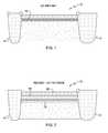
- FIG. 1shows a ground plant (GP) implant in a semiconductor structure.
- FIG. 2illustrates SiGe and Si layers epitaxial grown in a recess formed in the semiconductor structure of FIG. 1 .
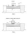
- FIG. 3depicts a gate formed on the semiconductor structure.
- FIG. 4shows a disposable spacer on the gate, and a source/drain implant.
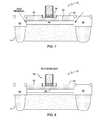
- FIG. 5shows an offset spacer around the gate of the semiconductor structure.
- FIG. 6illustrates recesses formed in isolation regions of the semiconductor structure.
- FIG. 7depicts removal of an SiGe layer from the semiconductor structure.
- FIG. 8shows an annealing step
- FIG. 9illustrates formation of a stress layer inside the semiconductor structure.
- the present inventionrelates to ICs. More particularly, the present invention relates to integrated circuits having stress liners which improve reliability and performance without incurring area penalties or layout inefficiencies.
- the inventioncan be applied to various types of ICs, such as memory devices including dynamic random access memories (DRAMs), static random access memories (SRAMs), non-volatile memories including programmable read-only memories (PROM) and flash memories, optoelectronic devices, logic devices, communication devices, digital signal processors (DSPs), microcontrollers, system-on-chip, as well as other types of devices.
- DRAMsdynamic random access memories
- SRAMsstatic random access memories
- PROMprogrammable read-only memories
- DSPsdigital signal processors
- microcontrollerssystem-on-chip, as well as other types of devices.
- FIG. 1illustrates a semiconductor substrate 10 that may be a conventional semiconductor substrate including isolation regions 14 .
- the base semiconductor substrate 10may comprise any semiconductor material including, but not limited to: Si, SiC, SiGe, SiGeC, Ge alloys, GaAs, InAs, InP, other III-V or II-VI compound semiconductors, or organic semiconductor structures.
- the base semiconductor substrate 10may be comprised of a Si-containing semiconductor material, i.e., a semiconductor material that includes silicon. Further, the base semiconductor substrate 10 may be doped or contain both doped and undoped regions.
- the base semiconductor substrate 10may be a bulk semiconductor structure, it may also include a layered structure with one or more buried insulator layers (not shown).
- Isolation regions 14are provided to separate the structure shown in FIG. 1 from adjacent semiconductor structures.
- the isolation regionscomprise shallow trench isolation (STI) regions.
- STIscomprise trenches formed in the substrate 10 and filled with dielectric material, such as silicon oxide. Other types of isolation regions may also be used.
- trenches 14may be formed by lithography and etching.
- the lithography stepincludes applying a photoresist to the surface of the substrate 10 , exposing the photoresist and developing the exposed photoresist using a conventional resist developer.
- the etching step used in forming the trenches 14may includes any standard Si directional reactive ion etch process. Other dry etching processes such as plasma etching, ion beam etching and laser ablation may also be employed. Portions of the substrate 10 that are protected by the patterned photoresist are not removed during etching. After etching, the patterned photoresist is removed utilizing a conventional resist stripping process.
- a high energy, ground plant (GP) implantis performed to form a layer 16 of high concentration silicon within the semiconductor substrate 10 .
- Any suitable GP proceduremay be used to form layer 16 .
- the portion of substrate 10 above that layeris etched away to form a recess at the top of the semiconductor recess.
- a SiGe layer 18is epitaxially grown on layer 16
- a Si layer 20is grown on that SiGe layer 18 . Any suitable procedures may be used to form this recess and to grow epitaxially layers 18 and 20 .
- the recess etchmay be any suitable etch process.
- a standard plasma etch machinemay be used at a temperature of 40-100° C., a pressure of 1-10 torr, and with HBr, CF 4 , and O 2 precursor gases.
- the epitaxial SiGe layer 18may be formed by any suitable standard process. For example, reduced-temperature chemical vapor deposition (“RTCVD”), ultra-high vacuum chemical vapor deposition (“UHCVD”), molecular beam epitaxy (“MBE”), or a small or large batch furnace-based process may be used.
- RTCVDreduced-temperature chemical vapor deposition
- UHCVDultra-high vacuum chemical vapor deposition
- MBEmolecular beam epitaxy
- a silicon-bearing precursor DCS (dichlorosilane), a germanium-bearing precursor GeH 4 (germane), and a p-doping precursor B 2 H 6 (diborane)may be used to grow a SiGe layer.
- the epitaxial deposition processmay also include a carbon-bearing precursor SiH 3 CH 3 (mono-methyl-silane).
- a RTCVD processmay be used at a temperature range of 450-800° C. and a
- the silicon layer 20is epitaxially grown on the SiGe layer 18 .
- the Si layermay comprise any semiconducting material including, but not limited to Si, strained Si, SiC, SiGe, SiGeC, Si alloys, Ge, Ge alloys, GaAs, InAs, and InP, or any combination thereof.
- a number of different sourcesmay be used for the deposition of epitaxial silicon. Silicon sources for epitaxial growth include silicon tetrachloride, dichlorosilane (SiH 2 Cl 2 ), and silane (SiH 4 ).
- the temperature for epitaxial silicon depositiontypically ranges from 550° C. to 900° C. Although a higher temperature typically results in faster deposition, the faster deposition may result in crystal defects and film cracking.
- a gate regionis then formed.
- a blanket layer of gate dielectric 22is formed on the surface of the layer 20 .
- the gate dielectric 22is comprised of an insulating material having a dielectric constant of, for example, about 4.0 or greater. In one embodiment, dielectric 22 may have a dielectric constant greater than 7.0.
- the dielectric constants mentioned hereinare relative to a vacuum, unless otherwise stated. Note that SiO 2 typically has a dielectric constant that is about 4.0.
- the gate dielectric 22 employed in the present inventionincludes, but is not limited to: an oxide, nitride, oxynitride and/or silicates including metal silicates, aluminates, titanates and nitrides.
- the gate dielectric 22may be comprised of an oxide such as, for example, SiO 2 , HfO 2 , ZrO 2 , Al 2 O 3 , TiO 2 , La 2 O 3 , SrTiO 3 , LaAlO 3 , Y 2 O 3 and mixtures thereof.
- the gate dielectric 22can be formed by a thermal growing process such as, for example, oxidation.
- the gate dielectric 22can be formed by a deposition process such as, for example, chemical vapor deposition (CVD), plasma-assisted CVD, atomic layer or pulsed deposition (ALD or ALPD), evaporation, reactive sputtering, chemical solution deposition or other like deposition processes.
- CVDchemical vapor deposition
- ALD or ALPDatomic layer or pulsed deposition
- evaporationreactive sputtering
- chemical solution deposition or other like deposition processeschemical solution deposition or other like deposition processes.
- the gate dielectric 22may also be formed utilizing any combination of the above processes.
- the physical thickness of the gate dielectric 22may vary, but typically, the gate dielectric 22 has a thickness from about 0.5 to about 10 nm, with a thickness from about 0.5 to about 2 nm being more typical.
- a blanket layer of polysilicon or another gate conductor material or combination thereof, which becomes the gate conductor 24 shown in FIG. 3is formed on the gate dielectric 22 utilizing a known deposition process such as, for example, physical vapor deposition, CVD or evaporation.
- the thickness, i.e., height, of the gate conductor 24 deposited at this point of the processmay vary depending on the deposition process employed.
- the gate conductor 24has a vertical thickness from about 20 to about 180 nm, with a thickness from about 40 to about 150 nm being more typical.
- the gate conductor 24can comprise any conductive material that is typically employed as a gate of a CMOS structure.
- conductive materialsthat can be employed as the gate conductor 24 include, but are not limited to: polysilicon, conductive metals or conductive metal alloys, conductive silicides, conductive nitrides, polySiGe and combinations thereof, including multilayers thereof.
- a barrier layermay be formed between multiple layers of gate conductors.
- the blanket layer of gate conductor material 24may be doped or undoped. If doped, an in-situ doping deposition process may be employed in forming the same. Alternatively, a doped gate conductor layer can be formed by deposition, ion implantation and annealing.
- dopant ionsinclude As, P, B, Sb, Bi, In, Al, Ga, Ti or mixtures thereof.
- a disposable spacer 26may be used during the doping of the gate conductor.
- the disposable spacer 26is formed over the sidewalls of the gate electrode 24 .
- the disposable spacercan be comprised of any suitable material; and for example this spacer can be comprised of photoresist, organic material, or anti-reflective coating (ARC) organic material.
- ARCanti-reflective coating
- an Anti-Reflective Coatingcan be comprised of a material such as propylene glycol monomethyl ether.
- the disposable spacercan be formed by forming an organic layer (such as a ARC layer) over the substrate and gate structure. Then the organic layer may be anisotropically RIE etched to form the disposable spacer.
- the disposable spacer 26can have a width between 10 and 1000 angstroms.
- An optional dielectric cap(not shown), such as an oxide or a nitride, may be formed on the gate conductor 24 .
- the optional dielectric capis typically removed before or immediately after the diffusion regions to be subsequently formed have been silicided.
- a conventional deposition processsuch as CVD or PECVD can be used in forming this optional dielectric cap.
- the optional dielectric capmay have a thickness from about 10 to about 50 nm.
- diffusion regions 32 and 34are formed utilizing a conventional deep ion implantation process.
- the diffusion regions 32 , 34which subsequently become the source/drain regions, may have a junction depth that is less than 50 nm.
- the diffusion regionsare present on each side of the gate structure 22 , 24 , 26 at the footprint thereof.
- the region between the diffusion regions 32 , 34 directly beneath the gate structure 22 , 24 , 26is the device channel 36 .
- the blanket gate conductor 24 , the gate dielectric 22 and optionally the dielectric capare then patterned by lithography and etching so as to provide at least one patterned gate region shown in FIG. 5 at 40 .
- the patterned gate regionsmay have the same dimension, i.e., length, or they can have variable dimensions to improve device performance.
- Each patterned gate region at this point of the fabrication processmay include at least a stack of the gate conductor 24 and the gate dielectric 22 .
- the lithography stepincludes applying a photoresist to the upper surface of the gate conductor 24 , exposing the photoresist to a desired pattern of radiation and developing the exposed photoresist utilizing a conventional resist developer.
- the pattern in the photoresistis then transferred to the blanket layer of gate conductor 24 and the gate dielectric 22 utilizing one or more dry etching steps.
- the patterned photoresistmay be removed after the pattern has been transferred into the blanket layer of gate conductor 24 .
- the photoresistmay be applied to the cap and the above processing is performed.
- Suitable dry etching processesthat can be used in forming the patterned gate region 40 include, but are not limited to: reactive-ion etching, ion beam etching, plasma etching or laser ablation.
- a wet or dry etching processcan also be used to remove portions of the gate dielectric 22 that are not protected by the patterned gate conductor 24 .
- Disposable spacer 26is removed and, with reference to FIG. 5 , an offset spacer (i.e., diffusion spacer) 42 is formed on exposed sidewalls of each patterned gate region.
- the offset spacer 42is comprised of an insulator such as an oxide, nitride, oxynitride, or carbon-containing silicon oxide, nitride, oxynitride, and/or any combination thereof.
- the offset spacer 42can be formed by deposition and etching or by thermal techniques.
- the width of the offset spacer 42may be adjusted to compensate for different diffusion rates of p-type dopants and n-type dopants that are used in forming the diffusion regions 32 and 34 .
- the offset spacer 42has a lateral width from about 3 to about 20 nm, with a lateral width from about 7 to about 15 nm being even more typical.
- the width of the offset spacercan be scaled below 3 nm or even eliminated if an advanced thermal process such as a laser anneal is used in activating the dopants within the diffusion regions 32 , 34 .
- a halo implantmay be performed at this point of the process utilizing a conventional halo ion implantation process. Although a halo ion implantation can be used, it does not represent the formation of another diffusion region. The structure including the diffusion regions 32 and 34 and offset spacer 42 is shown in FIG. 5 . Alternatively, for device silicon thickness under 10 nm, a halo implant is not typically required as the device threshold voltage becomes controlled more strongly by the gate electrode.
- the next step, illustrated in FIG. 6is a selective etching of the isolation trenches 14 to form recesses 46 , until lateral access is provided to the SiGe layer 18 .
- This etchingmay be performed in a conventional manner, for example by an anisotropic plasma etch.
- the processthen continues, as illustrated in FIG. 7 , with the removal of the SiGe layer 18 by selective lateral etching.
- SiGecan be removed, either by oxidizing chemistry (such as by etching with a solution having 40 ml of 70% HNO 3 +20 ml of H 2 O 2 +5 ml of 0.5% HF) or by isotropic plasma etching.
- FIG. 7illustrates a view of the substrate 10 after the etching of the trenches 14 and lateral etching of the SiGe layer 18 .
- there is an empty void 44 under the silicon epilayer 20and more specifically, directly beneath channel region 36 .
- Layer 20 and gate region 40may be physically supported above void 44 in any suitable way.
- layer 20may be anchored at STI regions (not shown) located above and below the plane of FIG. 7 .
- supports(not shown) may be located around the void 44 to maintain the structure.
- an annealing stepis performed to activate ions at the source and drain regions 32 , 34 .
- Any suitable annealing processmay be employed, and for instance, a Rapid Thermal Anneal (RTA) may be used.
- RTARapid Thermal Anneal
- the structuremay be put into the chamber of the RTA device, and heated to a temperature range between 300° C. and 600° C. for 1 to 5 minutes in an N 2 and O 2 environment. This treatment may be carried out at 0.5 to 1.5 atm using the N 2 and O 2 gas, respectively.
- the stress inducing materialcomprises a tensile stress inducing material, and, for example, silicon nitride may be used.
- the thickness of the tensile stress layerfor example, is about 400-1000 ⁇ and preferably about 500 ⁇ . Other thicknesses may also be useful.
- Various techniquescan be used to form the tensile stress layer.
- the first stress layercan be formed using chemical deposition techniques, such as low pressure CVD (LPCVD), plasma enhanced CVD (PECVD), rapid thermal CVD (RTCVD) or BTBAS-based CVD.
- the tensile stress layerin accordance with one embodiment of the invention, may be deposited by PECVD using a SiH 4 precursor.
- the stress layercomprises compressive stress material, and, for example, silicon nitride may also be used to form a compressive stress layer.
- the thickness of the stress layeris about 400-1000 ⁇ .
- the thickness of the second stress layeris about 600 ⁇ .
- Other thicknessesare also useful.
- Various techniquessuch as low pressure CVD (LPCVD), plasma enhanced CVD (PECVD), high density plasma CVD (HDPCVD), rapid thermal CVD (RTCVD) or BTBAS-based CVD can be used to form the second stress layer.
- the second stress layeris formed by HDPCVD using a silane (SiH 4 ) precursor.
- both tensile and compressive stress linersmay be formed in void 44 .
- substrate 10may be provided with both P-type and N-type transistors, with the P-type transistor directly above the compressive stress liner, and the N-type transistor directly above the tensile stress liner.
- silicidemay be added at the ends of the stress liner to form end caps 60 .
- the processthen continues with the filling of the trenches 14 with a dielectric. This dielectric may be the same as that used in the STI process.
- a final spacer 62may be added around gate structure 22 , 24 , and a top silicon layer 64 may be added on the semiconductor substrate.
- Spacer 62 and layer 64may be formed or added in any suitable way, and, for example, conventional techniques may be used.
- a buried oxide (BOX) layermay be formed in substrate 10 .
- a BOX layermay be formed in any suitable way.
- the initial substrate 10can be formed using a layer transfer process, such as a bonding process, in which a BOX is formed.
- a technique referred to as separation by implanted oxygen (SIMOX)can be used to form a BOX layer.
- ionstypically oxygen
- the substrate containing the implanted ionsis annealed under conditions that are capable of forming a buried insulating layer, i.e., BOX.
- the device illustrated in FIG. 9is then obtained.
Landscapes
- Insulated Gate Type Field-Effect Transistor (AREA)
- Metal-Oxide And Bipolar Metal-Oxide Semiconductor Integrated Circuits (AREA)
- Thin Film Transistor (AREA)
Abstract
Description
Claims (16)
Priority Applications (5)
| Application Number | Priority Date | Filing Date | Title |
|---|---|---|---|
| US12/575,962US8138523B2 (en) | 2009-10-08 | 2009-10-08 | Semiconductor device having silicon on stressed liner (SOL) |
| JP2010226294AJP5671294B2 (en) | 2009-10-08 | 2010-10-06 | Integrated circuit and manufacturing method thereof |
| KR1020100098494AKR20110038594A (en) | 2009-10-08 | 2010-10-08 | Semiconductor device with silicon (SOL) on stress liner |
| US13/365,764US8399933B2 (en) | 2009-10-08 | 2012-02-03 | Semiconductor device having silicon on stressed liner (SOL) |
| US13/765,830US8664058B2 (en) | 2009-10-08 | 2013-02-13 | Semiconductor device having silicon on stressed liner (SOL) |
Applications Claiming Priority (1)
| Application Number | Priority Date | Filing Date | Title |
|---|---|---|---|
| US12/575,962US8138523B2 (en) | 2009-10-08 | 2009-10-08 | Semiconductor device having silicon on stressed liner (SOL) |
Related Child Applications (1)
| Application Number | Title | Priority Date | Filing Date |
|---|---|---|---|
| US13/365,764DivisionUS8399933B2 (en) | 2009-10-08 | 2012-02-03 | Semiconductor device having silicon on stressed liner (SOL) |
Publications (2)
| Publication Number | Publication Date |
|---|---|
| US20110084315A1 US20110084315A1 (en) | 2011-04-14 |
| US8138523B2true US8138523B2 (en) | 2012-03-20 |
Family
ID=43854138
Family Applications (3)
| Application Number | Title | Priority Date | Filing Date |
|---|---|---|---|
| US12/575,962Expired - Fee RelatedUS8138523B2 (en) | 2009-10-08 | 2009-10-08 | Semiconductor device having silicon on stressed liner (SOL) |
| US13/365,764ActiveUS8399933B2 (en) | 2009-10-08 | 2012-02-03 | Semiconductor device having silicon on stressed liner (SOL) |
| US13/765,830ActiveUS8664058B2 (en) | 2009-10-08 | 2013-02-13 | Semiconductor device having silicon on stressed liner (SOL) |
Family Applications After (2)
| Application Number | Title | Priority Date | Filing Date |
|---|---|---|---|
| US13/365,764ActiveUS8399933B2 (en) | 2009-10-08 | 2012-02-03 | Semiconductor device having silicon on stressed liner (SOL) |
| US13/765,830ActiveUS8664058B2 (en) | 2009-10-08 | 2013-02-13 | Semiconductor device having silicon on stressed liner (SOL) |
Country Status (3)
| Country | Link |
|---|---|
| US (3) | US8138523B2 (en) |
| JP (1) | JP5671294B2 (en) |
| KR (1) | KR20110038594A (en) |
Cited By (6)
| Publication number | Priority date | Publication date | Assignee | Title |
|---|---|---|---|---|
| US20120126289A1 (en)* | 2005-06-30 | 2012-05-24 | Freescale Semiconductor, Inc. | Method of forming a semiconductor structure |
| US20120235238A1 (en)* | 2011-03-16 | 2012-09-20 | International Business Machines Corporation | Fully-depleted son |
| US8664058B2 (en)* | 2009-10-08 | 2014-03-04 | International Business Machines Corporation | Semiconductor device having silicon on stressed liner (SOL) |
| US8928082B2 (en)* | 2013-02-26 | 2015-01-06 | Semiconductor Manufacturing International (Shanghai) Corporation | JLT (junction-less transistor) device and method for fabricating the same |
| US9472445B2 (en) | 2013-12-23 | 2016-10-18 | Samsung Electronics Co., Ltd. | Semiconductor memory device and method of fabricating the same |
| US10043903B2 (en) | 2015-12-21 | 2018-08-07 | Samsung Electronics Co., Ltd. | Semiconductor devices with source/drain stress liner |
Families Citing this family (9)
| Publication number | Priority date | Publication date | Assignee | Title |
|---|---|---|---|---|
| JP2012221560A (en) | 2011-04-04 | 2012-11-12 | Yazaki Corp | Electric wire holder and room lamp for vehicle with the same |
| US20130137238A1 (en)* | 2011-11-30 | 2013-05-30 | Taiwan Semiconductor Manufacturing Company, Ltd. | Method for forming high mobility channels in iii-v family channel devices |
| CN103730361B (en)* | 2012-10-10 | 2018-02-13 | 中国科学院微电子研究所 | Semiconductor device manufacturing method |
| US8878251B2 (en)* | 2012-10-17 | 2014-11-04 | Seoul National University R&Db Foundation | Silicon-compatible compound junctionless field effect transistor |
| US10170315B2 (en)* | 2013-07-17 | 2019-01-01 | Globalfoundries Inc. | Semiconductor device having local buried oxide |
| US9252272B2 (en)* | 2013-11-18 | 2016-02-02 | Globalfoundries Inc. | FinFET semiconductor device having local buried oxide |
| JP6275559B2 (en) | 2014-06-13 | 2018-02-07 | ルネサスエレクトロニクス株式会社 | Semiconductor device and manufacturing method thereof |
| US9368343B1 (en) | 2015-01-07 | 2016-06-14 | International Business Machines Corporation | Reduced external resistance finFET device |
| CN119767749A (en)* | 2025-02-28 | 2025-04-04 | 北京中科新微特科技开发股份有限公司 | Semiconductor device and method for manufacturing the same |
Citations (17)
| Publication number | Priority date | Publication date | Assignee | Title |
|---|---|---|---|---|
| US6717216B1 (en) | 2002-12-12 | 2004-04-06 | International Business Machines Corporation | SOI based field effect transistor having a compressive film in undercut area under the channel and a method of making the device |
| US20040126985A1 (en) | 2002-12-30 | 2004-07-01 | Bendernagel Robert E. | Formation of patterned silicon-on-insulator (SOI)/silicon-on-nothing (SON) composite structure by porous Si engineering |
| US20040235262A1 (en) | 2003-05-20 | 2004-11-25 | Sharp Laboratories Of America, Inc. | Silicon-on-nothing fabrication process |
| US20050020085A1 (en) | 2003-07-22 | 2005-01-27 | Sharp Laboratories Of America, Inc. | Fabrication of silicon-on-nothing (SON) MOSFET fabrication using selective etching of Si1-xGex layer |
| US20050214997A1 (en) | 2004-03-23 | 2005-09-29 | Sharp Laboratories Of America, Inc. | Method to form local "silicon-on-nothing" or "silicon-on-insulator" wafers with tensile-strained silicon |
| US20060081836A1 (en) | 2004-10-14 | 2006-04-20 | Yoshinobu Kimura | Semiconductor device and method of manufacturing the same |
| US20060208342A1 (en) | 2005-03-17 | 2006-09-21 | Korea Advanced Institute Of Science And Technology | Silicon-on-nothing metal oxide semiconductor field effect transistor and method of manufacturing the same |
| US20070158743A1 (en) | 2006-01-11 | 2007-07-12 | International Business Machines Corporation | Thin silicon single diffusion field effect transistor for enhanced drive performance with stress film liners |
| US20070277728A1 (en) | 2006-05-30 | 2007-12-06 | Sadaka Mariam G | Method for forming a semiconductor structure having a strained silicon layer |
| US20080157292A1 (en) | 2006-12-29 | 2008-07-03 | Texas Instruments Inc. | High-stress liners for semiconductor fabrication |
| US20080283824A1 (en)* | 2003-11-05 | 2008-11-20 | International Business Machines Corporation, | Method and structure for forming strained si for cmos devices |
| US20090014807A1 (en) | 2007-07-13 | 2009-01-15 | Chartered Semiconductor Manufacturing, Ltd. | Dual stress liners for integrated circuits |
| US20090014808A1 (en) | 2007-07-15 | 2009-01-15 | Kyoung-Woo Lee | Methods For Forming Self-Aligned Dual Stress Liners For CMOS Semiconductor Devices |
| US20090032874A1 (en) | 2007-07-05 | 2009-02-05 | Stmicroelectronics Sa | Method for integrating silicon-on-nothing devices with standard cmos devices |
| US20090090974A1 (en) | 2007-10-08 | 2009-04-09 | International Business Machines Corporation | Dual stress liner structure having substantially planar interface between liners and related method |
| US20090184374A1 (en) | 2008-01-22 | 2009-07-23 | International Business Machines Corporation | Anisotropic stress generation by stress-generating liners having a sublithographic width |
| US20090212329A1 (en)* | 2007-06-05 | 2009-08-27 | International Business Machines Corporation | Super hybrid soi cmos devices |
Family Cites Families (8)
| Publication number | Priority date | Publication date | Assignee | Title |
|---|---|---|---|---|
| JP4258034B2 (en)* | 1998-05-27 | 2009-04-30 | ソニー株式会社 | Semiconductor device and manufacturing method of semiconductor device |
| JP2006108403A (en)* | 2004-10-06 | 2006-04-20 | Seiko Epson Corp | Semiconductor device and manufacturing method of semiconductor device |
| US7262087B2 (en)* | 2004-12-14 | 2007-08-28 | International Business Machines Corporation | Dual stressed SOI substrates |
| US7659581B2 (en)* | 2005-11-30 | 2010-02-09 | International Business Machines Corporation | Transistor with dielectric stressor element fully underlying the active semiconductor region |
| JP5055846B2 (en)* | 2006-06-09 | 2012-10-24 | ソニー株式会社 | Semiconductor device and manufacturing method thereof |
| JP2008004795A (en)* | 2006-06-23 | 2008-01-10 | Seiko Epson Corp | Manufacturing method of semiconductor device |
| JP2009164217A (en)* | 2007-12-28 | 2009-07-23 | Seiko Epson Corp | Semiconductor device manufacturing method and semiconductor device |
| US8138523B2 (en)* | 2009-10-08 | 2012-03-20 | International Business Machines Corporation | Semiconductor device having silicon on stressed liner (SOL) |
- 2009
- 2009-10-08USUS12/575,962patent/US8138523B2/ennot_activeExpired - Fee Related
- 2010
- 2010-10-06JPJP2010226294Apatent/JP5671294B2/ennot_activeExpired - Fee Related
- 2010-10-08KRKR1020100098494Apatent/KR20110038594A/ennot_activeWithdrawn
- 2012
- 2012-02-03USUS13/365,764patent/US8399933B2/enactiveActive
- 2013
- 2013-02-13USUS13/765,830patent/US8664058B2/enactiveActive
Patent Citations (17)
| Publication number | Priority date | Publication date | Assignee | Title |
|---|---|---|---|---|
| US6717216B1 (en) | 2002-12-12 | 2004-04-06 | International Business Machines Corporation | SOI based field effect transistor having a compressive film in undercut area under the channel and a method of making the device |
| US20040126985A1 (en) | 2002-12-30 | 2004-07-01 | Bendernagel Robert E. | Formation of patterned silicon-on-insulator (SOI)/silicon-on-nothing (SON) composite structure by porous Si engineering |
| US20040235262A1 (en) | 2003-05-20 | 2004-11-25 | Sharp Laboratories Of America, Inc. | Silicon-on-nothing fabrication process |
| US20050020085A1 (en) | 2003-07-22 | 2005-01-27 | Sharp Laboratories Of America, Inc. | Fabrication of silicon-on-nothing (SON) MOSFET fabrication using selective etching of Si1-xGex layer |
| US20080283824A1 (en)* | 2003-11-05 | 2008-11-20 | International Business Machines Corporation, | Method and structure for forming strained si for cmos devices |
| US20050214997A1 (en) | 2004-03-23 | 2005-09-29 | Sharp Laboratories Of America, Inc. | Method to form local "silicon-on-nothing" or "silicon-on-insulator" wafers with tensile-strained silicon |
| US20060081836A1 (en) | 2004-10-14 | 2006-04-20 | Yoshinobu Kimura | Semiconductor device and method of manufacturing the same |
| US20060208342A1 (en) | 2005-03-17 | 2006-09-21 | Korea Advanced Institute Of Science And Technology | Silicon-on-nothing metal oxide semiconductor field effect transistor and method of manufacturing the same |
| US20070158743A1 (en) | 2006-01-11 | 2007-07-12 | International Business Machines Corporation | Thin silicon single diffusion field effect transistor for enhanced drive performance with stress film liners |
| US20070277728A1 (en) | 2006-05-30 | 2007-12-06 | Sadaka Mariam G | Method for forming a semiconductor structure having a strained silicon layer |
| US20080157292A1 (en) | 2006-12-29 | 2008-07-03 | Texas Instruments Inc. | High-stress liners for semiconductor fabrication |
| US20090212329A1 (en)* | 2007-06-05 | 2009-08-27 | International Business Machines Corporation | Super hybrid soi cmos devices |
| US20090032874A1 (en) | 2007-07-05 | 2009-02-05 | Stmicroelectronics Sa | Method for integrating silicon-on-nothing devices with standard cmos devices |
| US20090014807A1 (en) | 2007-07-13 | 2009-01-15 | Chartered Semiconductor Manufacturing, Ltd. | Dual stress liners for integrated circuits |
| US20090014808A1 (en) | 2007-07-15 | 2009-01-15 | Kyoung-Woo Lee | Methods For Forming Self-Aligned Dual Stress Liners For CMOS Semiconductor Devices |
| US20090090974A1 (en) | 2007-10-08 | 2009-04-09 | International Business Machines Corporation | Dual stress liner structure having substantially planar interface between liners and related method |
| US20090184374A1 (en) | 2008-01-22 | 2009-07-23 | International Business Machines Corporation | Anisotropic stress generation by stress-generating liners having a sublithographic width |
Cited By (9)
| Publication number | Priority date | Publication date | Assignee | Title |
|---|---|---|---|---|
| US20120126289A1 (en)* | 2005-06-30 | 2012-05-24 | Freescale Semiconductor, Inc. | Method of forming a semiconductor structure |
| US8587070B2 (en)* | 2005-06-30 | 2013-11-19 | Freescale Semiconductor, Inc. | Method of forming a semiconductor structure |
| US8664058B2 (en)* | 2009-10-08 | 2014-03-04 | International Business Machines Corporation | Semiconductor device having silicon on stressed liner (SOL) |
| US20120235238A1 (en)* | 2011-03-16 | 2012-09-20 | International Business Machines Corporation | Fully-depleted son |
| US8455308B2 (en)* | 2011-03-16 | 2013-06-04 | International Business Machines Corporation | Fully-depleted SON |
| US8742504B2 (en) | 2011-03-16 | 2014-06-03 | International Business Machines Corporation | Fully-depleted son |
| US8928082B2 (en)* | 2013-02-26 | 2015-01-06 | Semiconductor Manufacturing International (Shanghai) Corporation | JLT (junction-less transistor) device and method for fabricating the same |
| US9472445B2 (en) | 2013-12-23 | 2016-10-18 | Samsung Electronics Co., Ltd. | Semiconductor memory device and method of fabricating the same |
| US10043903B2 (en) | 2015-12-21 | 2018-08-07 | Samsung Electronics Co., Ltd. | Semiconductor devices with source/drain stress liner |
Also Published As
| Publication number | Publication date |
|---|---|
| JP2011082519A (en) | 2011-04-21 |
| KR20110038594A (en) | 2011-04-14 |
| US8664058B2 (en) | 2014-03-04 |
| US20120199941A1 (en) | 2012-08-09 |
| US20130149823A1 (en) | 2013-06-13 |
| JP5671294B2 (en) | 2015-02-18 |
| US20110084315A1 (en) | 2011-04-14 |
| US8399933B2 (en) | 2013-03-19 |
Similar Documents
| Publication | Publication Date | Title |
|---|---|---|
| US8138523B2 (en) | Semiconductor device having silicon on stressed liner (SOL) | |
| CN106033757B (en) | High mobility device with anti-punch through layer and method of forming the same | |
| EP2641271B1 (en) | STRUCTURE AND METHOD FOR Vt TUNING AND SHORT CHANNEL CONTROL WITH HIGH K/METAL GATE MOSFETs | |
| US7226820B2 (en) | Transistor fabrication using double etch/refill process | |
| US10741453B2 (en) | FinFET device | |
| KR100845175B1 (en) | A bulk non-planar transistor having a strained channel with enhanced mobility and methods of fabrication | |
| US7838887B2 (en) | Source/drain carbon implant and RTA anneal, pre-SiGe deposition | |
| EP3188227A1 (en) | Fin-fet device and fabrication method thereof | |
| US8253177B2 (en) | Strained channel transistor | |
| KR101600553B1 (en) | Methods for fabricating mos devices having epitaxially grown stress-inducing source and drain regions | |
| US8114727B2 (en) | Disposable spacer integration with stress memorization technique and silicon-germanium | |
| US10665512B2 (en) | Stress modulation of nFET and pFET fin structures | |
| US20060234455A1 (en) | Structures and methods for forming a locally strained transistor | |
| US11688741B2 (en) | Gate-all-around devices with isolated and non-isolated epitaxy regions for strain engineering | |
| CN103155123A (en) | Method and structure for pFET junction profile with SiGe channel | |
| US9583378B2 (en) | Formation of germanium-containing channel region by thermal condensation utilizing an oxygen permeable material | |
| US7648880B2 (en) | Nitride-encapsulated FET (NNCFET) | |
| US11575003B2 (en) | Creation of stress in the channel of a nanosheet transistor |
Legal Events
| Date | Code | Title | Description |
|---|---|---|---|
| AS | Assignment | Owner name:INTERNATIONAL BUSINESS MACHINES CORPORATION, NEW Y Free format text:ASSIGNMENT OF ASSIGNORS INTEREST;ASSIGNORS:BEDELL, STEPHEN W.;CHANG, JOSEPHINE B.;LIN, CHUNG-HSUN;SIGNING DATES FROM 20090930 TO 20091001;REEL/FRAME:023346/0713 | |
| STCF | Information on status: patent grant | Free format text:PATENTED CASE | |
| AS | Assignment | Owner name:GLOBALFOUNDRIES U.S. 2 LLC, NEW YORK Free format text:ASSIGNMENT OF ASSIGNORS INTEREST;ASSIGNOR:INTERNATIONAL BUSINESS MACHINES CORPORATION;REEL/FRAME:036550/0001 Effective date:20150629 | |
| FPAY | Fee payment | Year of fee payment:4 | |
| AS | Assignment | Owner name:GLOBALFOUNDRIES INC., CAYMAN ISLANDS Free format text:ASSIGNMENT OF ASSIGNORS INTEREST;ASSIGNORS:GLOBALFOUNDRIES U.S. 2 LLC;GLOBALFOUNDRIES U.S. INC.;REEL/FRAME:036779/0001 Effective date:20150910 | |
| AS | Assignment | Owner name:WILMINGTON TRUST, NATIONAL ASSOCIATION, DELAWARE Free format text:SECURITY AGREEMENT;ASSIGNOR:GLOBALFOUNDRIES INC.;REEL/FRAME:049490/0001 Effective date:20181127 | |
| FEPP | Fee payment procedure | Free format text:MAINTENANCE FEE REMINDER MAILED (ORIGINAL EVENT CODE: REM.); ENTITY STATUS OF PATENT OWNER: LARGE ENTITY | |
| LAPS | Lapse for failure to pay maintenance fees | Free format text:PATENT EXPIRED FOR FAILURE TO PAY MAINTENANCE FEES (ORIGINAL EVENT CODE: EXP.); ENTITY STATUS OF PATENT OWNER: LARGE ENTITY | |
| STCH | Information on status: patent discontinuation | Free format text:PATENT EXPIRED DUE TO NONPAYMENT OF MAINTENANCE FEES UNDER 37 CFR 1.362 | |
| FP | Lapsed due to failure to pay maintenance fee | Effective date:20200320 | |
| AS | Assignment | Owner name:GLOBALFOUNDRIES INC., CAYMAN ISLANDS Free format text:RELEASE BY SECURED PARTY;ASSIGNOR:WILMINGTON TRUST, NATIONAL ASSOCIATION;REEL/FRAME:054636/0001 Effective date:20201117 | |
| AS | Assignment | Owner name:GLOBALFOUNDRIES U.S. INC., NEW YORK Free format text:RELEASE BY SECURED PARTY;ASSIGNOR:WILMINGTON TRUST, NATIONAL ASSOCIATION;REEL/FRAME:056987/0001 Effective date:20201117 |