US8137609B2 - Apparatus and method for cooling part cake in laser sintering - Google Patents
Apparatus and method for cooling part cake in laser sinteringDownload PDFInfo
- Publication number
- US8137609B2 US8137609B2US13/194,311US201113194311AUS8137609B2US 8137609 B2US8137609 B2US 8137609B2US 201113194311 AUS201113194311 AUS 201113194311AUS 8137609 B2US8137609 B2US 8137609B2
- Authority
- US
- United States
- Prior art keywords
- part cake
- build
- cake
- laser sintering
- enclosure
- Prior art date
- Legal status (The legal status is an assumption and is not a legal conclusion. Google has not performed a legal analysis and makes no representation as to the accuracy of the status listed.)
- Active
Links
- 238000000149argon plasma sinteringMethods0.000titleclaimsabstractdescription67
- 238000001816coolingMethods0.000titleclaimsabstractdescription40
- 238000000034methodMethods0.000titleclaimsdescription32
- 239000011261inert gasSubstances0.000claimsabstractdescription63
- 239000012809cooling fluidSubstances0.000claimsabstractdescription37
- 230000006835compressionEffects0.000claimsdescription23
- 238000007906compressionMethods0.000claimsdescription23
- 239000012530fluidSubstances0.000claimsdescription16
- 238000004519manufacturing processMethods0.000claims1
- 239000000843powderSubstances0.000abstractdescription70
- 230000003647oxidationEffects0.000abstractdescription12
- 238000007254oxidation reactionMethods0.000abstractdescription12
- 239000011148porous materialSubstances0.000abstractdescription2
- IJGRMHOSHXDMSA-UHFFFAOYSA-NAtomic nitrogenChemical compoundN#NIJGRMHOSHXDMSA-UHFFFAOYSA-N0.000description20
- 230000008569processEffects0.000description14
- 239000003570airSubstances0.000description10
- QVGXLLKOCUKJST-UHFFFAOYSA-Natomic oxygenChemical compound[O]QVGXLLKOCUKJST-UHFFFAOYSA-N0.000description10
- 239000001301oxygenSubstances0.000description10
- 229910052760oxygenInorganic materials0.000description10
- 230000007246mechanismEffects0.000description9
- 229910052757nitrogenInorganic materials0.000description9
- 238000006073displacement reactionMethods0.000description8
- 238000004891communicationMethods0.000description6
- 239000007789gasSubstances0.000description5
- 238000010438heat treatmentMethods0.000description5
- 230000009471actionEffects0.000description4
- 230000008859changeEffects0.000description4
- 230000008901benefitEffects0.000description3
- 229910001873dinitrogenInorganic materials0.000description3
- 239000000463materialSubstances0.000description3
- 238000000110selective laser sinteringMethods0.000description3
- CURLTUGMZLYLDI-UHFFFAOYSA-NCarbon dioxideChemical compoundO=C=OCURLTUGMZLYLDI-UHFFFAOYSA-N0.000description2
- 238000013461designMethods0.000description2
- 238000002845discolorationMethods0.000description2
- 239000002184metalSubstances0.000description2
- 238000012544monitoring processMethods0.000description2
- 229920000642polymerPolymers0.000description2
- 230000007480spreadingEffects0.000description2
- 239000004952PolyamideSubstances0.000description1
- 230000002411adverseEffects0.000description1
- 239000012080ambient airSubstances0.000description1
- 230000015572biosynthetic processEffects0.000description1
- 229910002092carbon dioxideInorganic materials0.000description1
- 239000001569carbon dioxideSubstances0.000description1
- UBAZGMLMVVQSCD-UHFFFAOYSA-Ncarbon dioxide;molecular oxygenChemical compoundO=O.O=C=OUBAZGMLMVVQSCD-UHFFFAOYSA-N0.000description1
- 239000000919ceramicSubstances0.000description1
- 238000011960computer-aided designMethods0.000description1
- 238000000151depositionMethods0.000description1
- 239000013013elastic materialSubstances0.000description1
- 238000003384imaging methodMethods0.000description1
- 238000003780insertionMethods0.000description1
- 230000037431insertionEffects0.000description1
- 238000002844meltingMethods0.000description1
- 230000008018meltingEffects0.000description1
- 239000000203mixtureSubstances0.000description1
- 230000004048modificationEffects0.000description1
- 238000012986modificationMethods0.000description1
- QJGQUHMNIGDVPM-UHFFFAOYSA-Nnitrogen groupChemical group[N]QJGQUHMNIGDVPM-UHFFFAOYSA-N0.000description1
- 239000012466permeateSubstances0.000description1
- 229920002647polyamidePolymers0.000description1
- 238000002360preparation methodMethods0.000description1
- 239000010453quartzSubstances0.000description1
- 238000011084recoveryMethods0.000description1
- 238000004064recyclingMethods0.000description1
- 238000007789sealingMethods0.000description1
- VYPSYNLAJGMNEJ-UHFFFAOYSA-Nsilicon dioxideInorganic materialsO=[Si]=OVYPSYNLAJGMNEJ-UHFFFAOYSA-N0.000description1
- 238000005245sinteringMethods0.000description1
- 239000007787solidSubstances0.000description1
- 230000000007visual effectEffects0.000description1
Images


Classifications
- B—PERFORMING OPERATIONS; TRANSPORTING
- B29—WORKING OF PLASTICS; WORKING OF SUBSTANCES IN A PLASTIC STATE IN GENERAL
- B29C—SHAPING OR JOINING OF PLASTICS; SHAPING OF MATERIAL IN A PLASTIC STATE, NOT OTHERWISE PROVIDED FOR; AFTER-TREATMENT OF THE SHAPED PRODUCTS, e.g. REPAIRING
- B29C35/00—Heating, cooling or curing, e.g. crosslinking or vulcanising; Apparatus therefor
- B29C35/16—Cooling
- B—PERFORMING OPERATIONS; TRANSPORTING
- B33—ADDITIVE MANUFACTURING TECHNOLOGY
- B33Y—ADDITIVE MANUFACTURING, i.e. MANUFACTURING OF THREE-DIMENSIONAL [3-D] OBJECTS BY ADDITIVE DEPOSITION, ADDITIVE AGGLOMERATION OR ADDITIVE LAYERING, e.g. BY 3-D PRINTING, STEREOLITHOGRAPHY OR SELECTIVE LASER SINTERING
- B33Y10/00—Processes of additive manufacturing
- B—PERFORMING OPERATIONS; TRANSPORTING
- B33—ADDITIVE MANUFACTURING TECHNOLOGY
- B33Y—ADDITIVE MANUFACTURING, i.e. MANUFACTURING OF THREE-DIMENSIONAL [3-D] OBJECTS BY ADDITIVE DEPOSITION, ADDITIVE AGGLOMERATION OR ADDITIVE LAYERING, e.g. BY 3-D PRINTING, STEREOLITHOGRAPHY OR SELECTIVE LASER SINTERING
- B33Y30/00—Apparatus for additive manufacturing; Details thereof or accessories therefor
- B—PERFORMING OPERATIONS; TRANSPORTING
- B33—ADDITIVE MANUFACTURING TECHNOLOGY
- B33Y—ADDITIVE MANUFACTURING, i.e. MANUFACTURING OF THREE-DIMENSIONAL [3-D] OBJECTS BY ADDITIVE DEPOSITION, ADDITIVE AGGLOMERATION OR ADDITIVE LAYERING, e.g. BY 3-D PRINTING, STEREOLITHOGRAPHY OR SELECTIVE LASER SINTERING
- B33Y40/00—Auxiliary operations or equipment, e.g. for material handling
- B33Y40/20—Post-treatment, e.g. curing, coating or polishing
- B—PERFORMING OPERATIONS; TRANSPORTING
- B29—WORKING OF PLASTICS; WORKING OF SUBSTANCES IN A PLASTIC STATE IN GENERAL
- B29C—SHAPING OR JOINING OF PLASTICS; SHAPING OF MATERIAL IN A PLASTIC STATE, NOT OTHERWISE PROVIDED FOR; AFTER-TREATMENT OF THE SHAPED PRODUCTS, e.g. REPAIRING
- B29C35/00—Heating, cooling or curing, e.g. crosslinking or vulcanising; Apparatus therefor
- B29C35/02—Heating or curing, e.g. crosslinking or vulcanizing during moulding, e.g. in a mould
- B29C35/08—Heating or curing, e.g. crosslinking or vulcanizing during moulding, e.g. in a mould by wave energy or particle radiation
- B29C35/0805—Heating or curing, e.g. crosslinking or vulcanizing during moulding, e.g. in a mould by wave energy or particle radiation using electromagnetic radiation
- B29C2035/0838—Heating or curing, e.g. crosslinking or vulcanizing during moulding, e.g. in a mould by wave energy or particle radiation using electromagnetic radiation using laser
- B—PERFORMING OPERATIONS; TRANSPORTING
- B29—WORKING OF PLASTICS; WORKING OF SUBSTANCES IN A PLASTIC STATE IN GENERAL
- B29C—SHAPING OR JOINING OF PLASTICS; SHAPING OF MATERIAL IN A PLASTIC STATE, NOT OTHERWISE PROVIDED FOR; AFTER-TREATMENT OF THE SHAPED PRODUCTS, e.g. REPAIRING
- B29C35/00—Heating, cooling or curing, e.g. crosslinking or vulcanising; Apparatus therefor
- B29C35/16—Cooling
- B29C2035/1658—Cooling using gas
- B29C2035/1666—Cooling using gas dried air
- B—PERFORMING OPERATIONS; TRANSPORTING
- B29—WORKING OF PLASTICS; WORKING OF SUBSTANCES IN A PLASTIC STATE IN GENERAL
- B29C—SHAPING OR JOINING OF PLASTICS; SHAPING OF MATERIAL IN A PLASTIC STATE, NOT OTHERWISE PROVIDED FOR; AFTER-TREATMENT OF THE SHAPED PRODUCTS, e.g. REPAIRING
- B29C35/00—Heating, cooling or curing, e.g. crosslinking or vulcanising; Apparatus therefor
- B29C35/16—Cooling
- B29C2035/1658—Cooling using gas
- B29C2035/1675—Cooling using gas other than air
- B29C2035/1683—Cooling using gas other than air inert gas
- B—PERFORMING OPERATIONS; TRANSPORTING
- B29—WORKING OF PLASTICS; WORKING OF SUBSTANCES IN A PLASTIC STATE IN GENERAL
- B29C—SHAPING OR JOINING OF PLASTICS; SHAPING OF MATERIAL IN A PLASTIC STATE, NOT OTHERWISE PROVIDED FOR; AFTER-TREATMENT OF THE SHAPED PRODUCTS, e.g. REPAIRING
- B29C2791/00—Shaping characteristics in general
- B29C2791/004—Shaping under special conditions
- B29C2791/005—Using a particular environment, e.g. sterile fluids other than air
- B—PERFORMING OPERATIONS; TRANSPORTING
- B29—WORKING OF PLASTICS; WORKING OF SUBSTANCES IN A PLASTIC STATE IN GENERAL
- B29C—SHAPING OR JOINING OF PLASTICS; SHAPING OF MATERIAL IN A PLASTIC STATE, NOT OTHERWISE PROVIDED FOR; AFTER-TREATMENT OF THE SHAPED PRODUCTS, e.g. REPAIRING
- B29C64/00—Additive manufacturing, i.e. manufacturing of three-dimensional [3D] objects by additive deposition, additive agglomeration or additive layering, e.g. by 3D printing, stereolithography or selective laser sintering
- B29C64/10—Processes of additive manufacturing
- B29C64/141—Processes of additive manufacturing using only solid materials
- B29C64/153—Processes of additive manufacturing using only solid materials using layers of powder being selectively joined, e.g. by selective laser sintering or melting
Definitions
- This inventionrelates to laser sintering for the formation of three-dimensional objects from fusible powders and more particularly relates to the cooling of such objects after the sintering has been completed.
- Laser sinteringis a solid imaging process for building three-dimensional objects, layer-by-layer, from a working medium utilizing sliced data sets representing cross sections of the object to be formed.
- an object representationis initially provided by a computer aided design (“CAD”) system.
- the laser sintering systemdispenses a thin layer of heat-fusible powder, normally a fusible polymer powder, polymer coated metal, metal, or ceramic, over a bed of the powder commonly referred to as the “part cake.”
- the laser sintering systemapplies thermal energy to melt those portions of the powder corresponding to a cross-section of the article being built in that powder layer.
- Laserstypically supply the thermal energy through modulation and precise directional control to a targeted area of the powder layer.
- Conventional selective laser sintering systemsuse carbon dioxide lasers and position the laser beam by way of galvanometer driven mirrors that deflect the laser beam.
- the part caketypically includes a movable build platform upon which the bed of powder is disposed. After a powder layer is fused, the build platform moves downward by an incremental distance. The system then dispenses an additional layer of powder onto the previously fused layer and repeats the process of melting and selective fusing of the powder in the next layer, with fused portions of later layers fusing to fused portions of previous layers as appropriate for the article, until the article is complete.
- objectssometimes referred to as “objects,” “parts,” or “builds;” and the “part cake” includes not only the build(s) but the unfused powder surrounding the build(s).
- Each additional layer of powdertypically is dispensed from a powder feed system that dispenses a measured amount of powder on the part cake.
- a powder spreadersuch as a blade or roller, then spreads the powder over the part cake bed in a uniform manner.
- a powder spreadersuch as a blade or roller, then spreads the powder over the part cake bed in a uniform manner.
- a newly formed buildmay require several hours or days to cool and, as a result, the laser sintering system may be inactive during the cooling time, which may cause the system to be unavailable for subsequent builds.
- laser sintering deviceshave been developed that include a removable build chamber in which the build platform and build are contained.
- the build chamber including the new buildmay be separated from the process chamber so that the part can be cooled outside the process chamber. Meanwhile, a fresh build chamber can be inserted and a new build can be prepared without waiting for the previous build to cool.
- the part cake(including the build) can be discolored if the part cake is removed from the laser sintering system while the part cake is above a certain temperature, for example 150° C., as the result of oxidation of the build and powder.
- the discolorationcan permeate many layers deep into the part cake relative to the outermost layer exposed to ambient conditions; therefore, conventional laser sintering systems typically require that the part cake remain in the laser sintering system a certain amount of time simply to prevent discoloration of the build.
- the inventionprovides methods and apparatus for cooling a part cake containing a build produced by laser sintering in which the part cake is compressed about the build to allow the un-fused powder to support the build against distortion during the cooling phase.
- Forced cooling fluidsuch as nitrogen, another inert gas, or air, is forced through the pore volume of the compressed part cake powder to rapidly cool the part cake substantially in the absence of distortion of the build dimensions.
- the inventionis an apparatus for cooling a part cake that comprises an enclosure for containing the part cake in which the enclosure has opposed displaceable wall portions that can be displaced from a laser sintering position to a part cake compression position and provides for forced cooling fluid to pass through the compressed part cake.
- the inventionis a method for cooling a part cake in which an enclosure is provided for the part cake that has displaceable wall portions that can be moved from a laser sintering position to a compression position. The displaceable wall portions are moved to a compression position to compress the part cake, and cooling fluid is forced through the part cake to cool the part cake.
- the part cakeis compressed to from less than about 50% of full density to about 70% of full density, full density being defined as that density achieved by fusing the fusible powder. At this higher bed density the part build inside the part cake is held rigidly in place during the cooling phase and suffers little distortion due to the rapid cooling.
- the enclosure for the part cakehas four sides, each of which is compressible by a displacement rod, and the four sides are designed in a nesting relationship that will allow them to be pushed inwardly from a laser sintering position to a part cake compression position.
- the bottom of the enclosureis formed by the build platform for the part cake, the build platform being movable within the enclosure and lowered within the enclosure as the build is prepared by laser sintering.
- the build platformhas passages formed for the passage of forced cooling fluid through the build platform and into the part cake during the cooling phase.
- the enclosurefits into a cooling housing that contains the displacement rods, and also includes a lid that functions as the lid for the enclosure and part cake as well as the cooling housing once the part cake has been removed from the laser sintering system.
- the part cakeis held in place against the application of forced cooling fluid by the housing lid that is placed on the part cake after the enclosure has been removed from the laser sintering system.
- This lidhas passages for cooling fluid to escape.
- the bottom of the housingprovides a fitting for a source of cooling fluid.
- the cooling fluidcan be nitrogen or another inert gas, or the cooling fluid can be air.
- the enclosurecan be redesigned for removal from the laser sintering system, and placed in the housing in a cooling station.
- the housing containing the enclosurenests in a wheeled cart that can be removed from the laser sintering system and placed in a cooling station for connection to a source of cooling fluid and for compression of the part cake, while a fresh cart with housing, enclosure and part cake is installed in the laser sintering system. In both cases, semi-continuous operation of the system is possible.
- inventions of the present inventioncomprise an inert gas blanket apparatus that is selectively used to cover the part cake and expose the part cake to an inert gas flow to prevent oxidation of the part cake while the part cake is removed from the laser sintering system.
- the inert gascomprises nitrogen
- further embodimentscomprise alternative inert gases (inert gas as defined herein is any gas that does not react chemically with the powder or fused powder of the part cake).
- the inert gas blanket apparatus of certain embodimentsincludes an inert gas supply, a controller with valve devices to selectively control the release of inert gas from the supply, and a lid with a passage to receive the inert gas from the supply and to allow the inert gas to generally expose the part cake to the inert gas to prevent oxidation of the part cake while the inert gas is supplied.
- Some embodiments of the present inventioninclude a gas sensor capable of monitoring the concentration of inert gas and/or oxygen in the air proximate the part cake for purposes of personnel protection.
- the inventionprovides, among other benefits, apparatus and methods for compressing a part cake to support a build against distortion and for speedier cooling with forced cooling fluid.
- the apparatuscan be used with older laser sintering systems adapted for removal of the build and part cake enclosure or with more updated systems having a build and part cake enclosure adapted to be removable for cooling in a separate station.
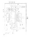
- FIG. 1is a schematic view of a conventional laser sintering system in connection with which the invention described herein may be applied.
- FIG. 2is a perspective view of a laser sintering system with exterior skin removed for clarity and showing both the part building system and a removable part cake enclosure.
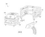
- FIG. 3illustrates in a perspective view an embodiment of portions of the apparatus of the invention in exploded relation, including a wheeled cart for inserting a laser sintering part cake into a laser sintering system.
- FIG. 4illustrates in a perspective view the components of FIG. 3 in assembled relation for laser sintering.
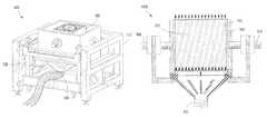
- FIG. 5illustrates in an exploded perspective additional components of the apparatus of FIG. 3 , including a lid for the part cake enclosure and enclosure housing.
- FIG. 6illustrates in an exploded perspective the wheeled cart of FIG. 3 inserting into a cooling station and a Source of cooling fluid for cooling the part cake in accordance with the invention.
- FIG. 7illustrates the assembly of the components of FIG. 6 in preparation for the cooling phase.
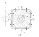
- FIG. 8is a top sectional partial plan view of the part cake enclosure and housing of the invention immediately before part cake compression.
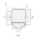
- FIG. 9is a side sectional plan view of the part cake enclosure and housing of the invention showing perforated top and bottom plates, compression of the part cake, and cooling fluid flow through the part cake.
- FIG. 10is a perspective view of the part cake enclosure of the invention.
- FIG. 11is a front plan view of an alternate part cake enclosure being inserted into an enclosure housing.
- FIG. 12is a view illustrating the alternate part cake enclosure in a compressed condition, with cooling fluid flowing through it.
- FIG. 13is an exploded perspective view similar to FIG. 5 , but illustrating the inert gas blanket apparatus of one embodiment of the present invention, wherein the controller and the inert gas supply are not shown to scale for illustrative purposes.
- FIG. 1shown generally as the numeral 150 , illustrates a conventional laser sintering system.
- An outer skin 151 of an industrial designsurrounds the working system.
- An optics scanning system 114directs a laser beam 154 from laser 108 .
- Laser beam 154enters through a laser window 156 that isolates laser 108 and optics 114 from the higher temperature environment inside a process chamber 152 .
- Radiant heating elements 160provide heat to target area 186 and to the areas immediately next to the target area. These radiant heaters 160 can be any number of types including for example quartz rods or flat panels.
- a single powder feed hopper 162is shown with a bottom feed mechanism 164 controlled by a motor (not shown) to control the amount of powder dropped onto the bed below.
- the feed mechanism 164can be of several types, including for example a star feeder, or a rotary drum feeder.
- Powder feed hopper 162is shown on the right hand side of the system but could be on the left hand side.
- a motor(not shown) controls part piston 170 to move downwardly below floor 206 of chamber 152 by a small amount, for example 0.125 mm, to define the thickness of each layer of powder to be processed.
- Roller 180is a counter-rotating roller driven by motor 182 that spreads powder from powder wave 184 across laser target area 186 . When traveling in either direction the roller carries any residual powder not deposited on the target area into overflow cartridges 188 on either end of the chamber.
- Target area 186refers to the top surface of heat-fusible powder (including portions previously sintered, if present) disposed above part piston 170 ; the sintered and unsintered powder disposed on part piston 170 will be referred to herein as part bed 190 .
- part bed 190the sintered and unsintered powder disposed on part piston 170 will be referred to herein as part bed 190 .
- a counter-rotating roller 180is shown the powder can also be spread by other means such as a wiper or a doctor blade.
- the selective laser sintering system shown in FIG. 1can be used as follows to build parts.
- powderis metered from hopper 162 to a position in front of roller 180 to form powder wave 184 .
- counter-rotating roller 180is activated to move powder wave 184 slightly forward and park it at the edge of target area 186 in view of radiant heater elements 160 for pre-heating purposes.
- roller 180is moved back and parked directly under feed hopper 162 .
- Laser 108is then turned on and scans the current layer to selectively fuse the powder on that layer while scanning roller 180 remains parked directly under powder feeder mechanism 164 .
- a second powder wave(not shown) is fed onto the top surface 183 of the roller mechanism.
- the roller 180is activated and traverses completely across target area 186 , spreading the first layer of pre-heated powder 184 across target area 186 , while carrying the second layer of powder on the top surface 183 of the roller mechanism.
- Mounted stationary blade 192dislodges the second layer of powder off the top surface 183 of the roller mechanism as the roller passes under the blade, depositing the second powder wave on the chamber floor while the roller proceeds to feed any excess powder into left overflow 188 .
- roller 180In the next step, roller 180 immediately reverses and moves to park the second powder wave near the left side of target area 186 and in sight of radiant heater elements 160 for pre-heating. In a next step, the roller 180 moves back to the left and parks while the laser action is completed and the second quantity of powder is being pre-heated by radiant heaters 160 . After the laser action is complete, the roller 180 is then activated and moves to the right to spread the second quantity of powder over target area 186 . After leveling the powder, the roller 180 proceeds to the end of its run and drops any excess powder into right overflow 188 . This completes the cycle. Repeated cycles result in the building of a completed part in part bed 190 to define a part cake.
- the collected overflow powder in overflows 188can in some implementations be part of a powder recycling system that returns powder to feed hopper 162 , or the overflows 188 can be used as simple collectors for later manual recycle of powder.
- FIG. 2shown generally by the numeral 200 , shows several key elements of a commercial selective laser sintering with the exterior skin removed for clarity.
- a central process chamber 205contains the radiant heating elements described in FIG. 1 and is where the build process, including the spreading and heating of powder, as well as the laser sintering of part builds is conducted.
- a powder feed hopper 210is located on the left hand side of process chamber 205 . Feed hopper 210 feeds powder to feed mechanism 215 (corresponding to mechanism 164 of FIG. 1 ).
- Overflow collectors 220 on either side of the systemcorrespond to overflows 188 of FIG. 1 .
- Left out (for clarity) in FIG. 2are the laser and optics systems that sit above process chamber 205 and direct the laser beam down through the laser window 225 on top of process chamber 205 .
- Rapid change module 230contains build chamber 235 (similar to part bed 190 of FIG. 1 ), which at the completion of a build contains all of the parts (sintered powder) and unsintered powder after a build, all of which defines the part cake in certain embodiments of the present invention.
- Rapid change module 230includes alignment mechanisms for ensuring that the build chamber 235 , and the part cake within, is aligned within the laser sintering system.
- the wheeled cartcan be removed from the laser sintering system and another wheeled cart with a build chamber can be inserted into the system.
- the system of FIG. 2has the advantage that the build chamber is easily removed and replaced with a different build chamber, increasing the efficiency of the build process.
- FIG. 3shown generally by the numeral 300 illustrates a modification of the laser sintering system of FIG. 2 in accordance with the present invention.
- the build chamber 305is contained within a separate housing 310 that is located on the wheeled cart 320 .
- the wheeled cart 320is inserted and aligned within a laser-sintering frame 315 of the laser sintering system.
- the build chamber 305has been raised into the laser sintering system to a position for laser sintering.
- the external housing 310 for the build chamberincludes displacement rods 325 provided on each side of the build chamber for moving the pairs of opposed displaceable wall portions of build chamber 305 to compress the part cake within the build chamber.
- This compression stepis performed after a laser sintering build has been removed from the laser sintering system of FIG. 2 .
- Compression of the part cake in build chamber 305supports the build during forced cooling by inert gas or air so that the build is not distorted by fast cooling or cooling more quickly in some areas than others. This compression is an aspect of the present invention.
- FIG. 5represented generally by the numeral 400 shows wheeled cart 320 , part cake enclosure 305 , and housing 310 removed from the laser sintering frame 315 and a lid 410 being placed on the housing for sealing the top of the part cake housing and chamber.
- Lid 410keeps the part cake (especially the unfused powder of the part cake) from being blown out of the chamber when forced cooling fluid is applied to the part cake to cool the build.
- the underside of lid 410is perforated so that cooling fluid can pass upwardly through the part cake for forced cooling of the build.
- FIG. 6represented generally by the numeral 500 illustrates wheeled cart 320 , removed from the laser sintering system, to be inserted into a cooling station frame 510 of similar design to the laser-sintering frame 315 of FIG. 5 . Also shown is a source of forced cooling fluid 520 for attachment to the part cake chamber and housing in order that the cooling fluid supplied will be in fluid communication with the part cake.
- FIG. 7shown generally by the numeral 600 illustrates the combination of the wheeled cart 320 within the cooling station frame 510 and attachment of the source of forced cooling fluid 520 to the underside of the housing directly to the underside of the part cake chamber 305 .
- the build platformis perforated so that cooling fluid from the source of forced cooling fluid rises upwardly through the build platform and part cake to exit through the perforated lid (not shown).
- FIG. 8shown generally by the numeral 700 , illustrates an aspect of the present invention.
- the displaceable wall portions of part cake chamber 305are offset at the corners so that the displacement rods 710 can compress the displaceable wall portions against the part cake to compress the part cake and support the build.
- the pairs of opposed displaceable wall portionsare moved inwardly in the direction of the arrows to compress the part cake from a laser sintering position to a part cake compression position and moved outwardly in the direction of the arrows to release the part cake from the part cake compression position.
- the part or build 720is held rigidly while the cooling fluid (inert gas or air) flows through the part cake to maintain the dimensional integrity of the part build as the temperature drops.
- pairs of opposed displaceable wall portionsare in displaceable relation whether only one or both wall portions are moveable, as it is necessary for only one wall portion to move relative to the other wall portion of the pair of opposed displaceable wall portions to define the displaceable relation.
- FIG. 9shown generally by the numeral 800 illustrates forced cooling fluid 810 applied through fluid passages of the perforated build platform 820 and exiting through the perforated lid 830 for the part cake chamber as the pair of opposed displaceable wall portions 840 of the part cake chamber have been moved inwardly to compress the part cake 845 .
- one or more wall portion of the pairs of opposed wall portionsinclude the fluid passages for supplying the cooling fluid through the part cake.
- the build platform 820 and the perforated lid 830are considered wall portions.
- the pair or pairs of opposed displaceable wall portions 840are considered opposed wall portions.
- the build 835is shown in dotted outline within the part cake and corresponds to part build 720 of FIG. 8 .
- displaceable wall portions 840When displaceable wall portions 840 are moved inwardly to compress the part cake 845 this is referred to as the part cake compression position. Before part cake 845 is compressed, displaceable wall portions 840 are in a part cake laser sintering position.
- the density of an uncompressed powder bedis usually close to pour densities (loose powder without any compressive forces exerted), which are about 40% dense.
- the mechanical compression of this inventioncan increase that density up to the 60-80% range. 100% density is defined as the density achieved by fusing the fusible powder. In this 60-80% range of compression the part builds 835 are rigidly supported and suffer little distortion due to high cooling rates.
- FIG. 10shown generally by the numeral 850 , illustrates the part cake enclosure 305 , which is a double walled enclosure having fixed external walls and having internal displaceable wall portions that are offset at the corners in a nesting relationship so that they can be moved inwardly to compress the part cake 865 , surrounding a part build 870 , to a part cake compression position.
- the corners of certain embodiments of the present inventioninclude a generally elastic material to permit movement of one or more wall portions without allowing unfused powder of the part cake to escape the enclosure when the wall portion(s) is/are moved.
- the part cake enclosure 305is precisely located within the wheeled cart via bolts 860 (shown in shadow).
- the present inventionalso includes methods for cooling a part cake containing a build produced by laser sintering.
- the part buildis first produced in a laser sintering system, resulting in a completed build that is still at an elevated temperature.
- the part cakewhich includes the build and the surrounding unfused powder, is then removed from the laser sintering system.
- the removed part cake in an enclosureis then covered with a porous lid and the part cake is compressed by action of the displacement rods against the opposed displaceable wall portions.
- a source of cooling fluidis then attached to the porous bottom of the part build enclosure and forced cooling fluid is passed through the compressed part cake, cooling the part cake, with the compression precluding the part build from distortion during the rapid cooling.
- the buildcan be removed from the part cake and the unfused powder can be removed from the enclosure (or the part cake can be removed from the enclosure) by techniques known in the art.
- FIG. 11shows generally by the numeral 900 .
- FIG. 11illustrates insertion of a modified part cake chamber 910 from an older system into a housing 920 having locators 930 for precisely locating the part cake chamber 910 and displacement rods 940 for compressing the interior displaceable wall portions 945 of the part cake chamber 910 against a part cake 925 and build 915 .
- the inventioncan be adapted for use with these older laser sintering devices by removing the completed build and part cake chamber from the laser sintering system and placing that part cake chamber within a housing having the displacement rods 940 and locators 930 as illustrated in FIG. 11 . As can be seen in FIG.
- part cake chamber 910enclosing part cake 925 with a completed part build 915 (in shadow) has been modified to include movable internal displaceable wall portions 945 , a perforated build platform 950 and a perforated lid 960 , and locators 930 for precise location within a cooling housing.
- displacement rods 940can be used to compress the part cake 925 into a part cake compression position while connected to a supply of forced cooling fluid. This is illustrated in FIG. 12 in which interior displaceable wall portions 945 have compressed part cake 925 and a supply of cooling fluid 935 has been applied to flow upward through part cake 925 to rapidly cool the rigidly supported part build 915 (in shadow).
- FIG. 13a further embodiment of the present invention is disclosed in which an inert gas blanket apparatus 400 ′ is used to prevent oxidation of the portions of the part cake that would otherwise oxidize when exposed to atmospheric conditions.
- oxidation of the part caketypically occurs when the part cake is at temperatures above about a certain amount, such as 150° C. for certain polyamide materials to provide one non-limiting example, and the part cake is exposed to oxygen in the atmosphere (the temperatures and rate of oxidation depend upon the particular material of the part cake and/or the size of the part cake).
- the oxidationundesirably discolors the part cake (including the build) and may adversely affect the material properties of the unfused powder (which is typically reused) and/or the build.
- the insert gas blanket apparatus of the present inventionallows the part cake to be safely removed from the laser sintering system without waiting for the part cake to cool to about 150° C. or less (which for some large part cakes can take 24 hours to cool down to about 150° C. when left in the laser sintering system and when no forced cooling fluid is provided as described above) and/or allows the part cake to be safely and/or quickly cooled while the part cake remains within the laser sintering system.
- the inert gas blanket apparatus 400 ′comprises a lid 410 ′ that selectively covers the part cake. For example, an operator may manually place the lid on the part cake, or automated equipment may be used to place the lid on the part cake.
- the lid 410 ′includes a passage that receives inert gas provided by an inert gas supply 420 ′.
- the inert gas supply 420 ′ of the illustrated embodimentis a nitrogen generator; however, further embodiments include alternative supplies for any inert gas, with one non-limiting example being a pure supply of nitrogen gas.
- the inert gas supplycomprises nitrogen generator
- the nitrogenis separated from the air in the surrounding atmosphere such that the total amounts of nitrogen, oxygen, carbon dioxide, and other gases in the room in which the laser sintering system and/or associated equipment are located is generally preserved despite the relative concentration of nitrogen proximate the inert gas blanket apparatus.
- the inert gas supplycomprises a pure supply of nitrogen gas
- the total amounts of individual gaseswill change with the increasing relative amount of nitrogen provided by the pure supply of nitrogen gas.
- the inert gas supply 420 ′ of FIG. 13provides the inert gas through a hose 430 ′ to the passage in the lid 410 ′ (such that the inert gas supply is in fluid communication with the passage of the lid), and after the inert gas passes through the passage, the inert gas is in fluid communication with the part cake, such that the inert gas forms a blanket that generally displaces oxygen or other non-inert gases that may otherwise come into contact with the part cake, thus reducing or eliminating oxidation of the part cake.
- the inert gas blanket of the present inventionalso comprises a controller 440 ′ that selective controls the flow of inert gas from the inert gas supply 420 ′ to the lid 410 ′.
- the controller 440 ′ of the exemplary embodiment of FIG. 13is in electrical communication with the inert gas supply 420 ′ via cable 450 ′ and is powered by power cord 460 ′; however further embodiments of the present invention may have alternative communication between the controller and inert gas supply and/or alternative power supplies for the controller.
- FIG. 13is illustrated with a compressor line 470 ′ connected to the inert gas supply in order to provide compressed air, such as from a standard compressor, to allow the inert gas supply to operate in a manner known in the art.
- a compressor line 470 ′connected to the inert gas supply in order to provide compressed air, such as from a standard compressor, to allow the inert gas supply to operate in a manner known in the art.
- Further embodiments of the present inventioninclude alternative inert gas supplies that may operate with or without compressed air.
- the controller 440 ′controls at least one valve device (not shown) in flow communication with hose 430 ′ to selectively release inert gas to the lid at a certain time, for a certain duration, and/or at a certain rate.
- the operatorplaces the lid on the part cake enclosure and activates the controller so that the inert gas flows to the passage of the lid.
- the controller 440 ′allows the operator to start and stop the flow of inert gas through hose 430 ′, to set a timer so that the controller automatically stops the flow of inert gas after a certain period of time (such amount of time being sufficient for the part cake to cool a desired amount), and/or to set the flow rate of the inert gas to ensure that a sufficient blanket of inert gas is provided to reduce or eliminate oxidation of the part cake and/or to cool the part cake adequately.
- Controllers of further embodiments of the present inventioninclude alternative and/or additional functions and controls to provide the desired protection and/or cooling of the part cake.
- the lidcomprises a top portion generally parallel to a top surface of the part cake when the lid is covering the part cake, and the passage is provided in the top surface of the part cake.
- the lid 410 ′also comprises sidewalls overhanging the sides of the part cake such that when the inert gas is supplied to the passage, the inert gas generally flows over the top surface of the part cake and between the sides of the part cake and the sidewalls of the lid to generally define a blanket of inert gas over the top surface of the part cake.
- the inert gasmay be provided through the passage and the lid may be configured such that the inert gas flows through the part cake and out one or more wall portions (such as the build platform to provide one non-limiting example) that define fluid passages to not only protect the part cake from oxidation but also cool the part as described above.
- Still further embodiments of the present inventioninclude alternative inert gas blanket apparatus for protecting the part cake from oxidation and/or cooling of the part cake.
- certain embodiments of the present inventionprovide inert gas that may mix with the ambient air surrounding the apparatus while or after the part cake is being cooled and/or blanketed, operators must be careful when operating the apparatus in confined areas in which the amount of oxygen in the air may drop below the amount needed for the operator to breath safely. Therefore, certain embodiments of the present invention include an inert gas sensor and/or an oxygen sensor, such as the oxygen sensor 480 ′ of FIG. 13 , for monitoring the amount of inert gas supplied and/or the amount of oxygen in the surrounding environment (in which the operator would be present) to ensure that a sale level of oxygen is available for the operator to breath.
- an inert gas sensor and/or an oxygen sensorsuch as the oxygen sensor 480 ′ of FIG. 13
- the apparatuswill alert the operator, via an audible and/or visual alarm, and/or will automatically shut off the flow of inert gas.
- Still further embodiments of the present inventioninclude additional and/or alternative safety features that may be used with the present invention if the operator will be using the apparatus in an area in which the oxygen in the air may be replaced with the inert gas to an unsafe level.
Landscapes
- Chemical & Material Sciences (AREA)
- Engineering & Computer Science (AREA)
- Manufacturing & Machinery (AREA)
- Materials Engineering (AREA)
- Physics & Mathematics (AREA)
- Health & Medical Sciences (AREA)
- Oral & Maxillofacial Surgery (AREA)
- Thermal Sciences (AREA)
- Powder Metallurgy (AREA)
Abstract
Description
Claims (12)
Priority Applications (1)
| Application Number | Priority Date | Filing Date | Title |
|---|---|---|---|
| US13/194,311US8137609B2 (en) | 2008-12-18 | 2011-07-29 | Apparatus and method for cooling part cake in laser sintering |
Applications Claiming Priority (2)
| Application Number | Priority Date | Filing Date | Title |
|---|---|---|---|
| US12/338,521US20100155985A1 (en) | 2008-12-18 | 2008-12-18 | Apparatus and Method for Cooling Part Cake in Laser Sintering |
| US13/194,311US8137609B2 (en) | 2008-12-18 | 2011-07-29 | Apparatus and method for cooling part cake in laser sintering |
Related Parent Applications (1)
| Application Number | Title | Priority Date | Filing Date |
|---|---|---|---|
| US12/338,521DivisionUS20100155985A1 (en) | 2008-12-18 | 2008-12-18 | Apparatus and Method for Cooling Part Cake in Laser Sintering |
Publications (2)
| Publication Number | Publication Date |
|---|---|
| US20110285061A1 US20110285061A1 (en) | 2011-11-24 |
| US8137609B2true US8137609B2 (en) | 2012-03-20 |
Family
ID=42264850
Family Applications (2)
| Application Number | Title | Priority Date | Filing Date |
|---|---|---|---|
| US12/338,521AbandonedUS20100155985A1 (en) | 2008-12-18 | 2008-12-18 | Apparatus and Method for Cooling Part Cake in Laser Sintering |
| US13/194,311ActiveUS8137609B2 (en) | 2008-12-18 | 2011-07-29 | Apparatus and method for cooling part cake in laser sintering |
Family Applications Before (1)
| Application Number | Title | Priority Date | Filing Date |
|---|---|---|---|
| US12/338,521AbandonedUS20100155985A1 (en) | 2008-12-18 | 2008-12-18 | Apparatus and Method for Cooling Part Cake in Laser Sintering |
Country Status (1)
| Country | Link |
|---|---|
| US (2) | US20100155985A1 (en) |
Cited By (12)
| Publication number | Priority date | Publication date | Assignee | Title |
|---|---|---|---|---|
| US20110252618A1 (en)* | 2010-04-17 | 2011-10-20 | Evonik Degussa Gmbh | Apparatus for reducing the size of the lower construction chamber of a laser sintering installation |
| CN105922343A (en)* | 2016-06-01 | 2016-09-07 | 安徽万朗磁塑集团有限公司 | Adjustable door seal gum cover cutting and pre-hardening device |
| US9969002B2 (en)* | 2016-07-13 | 2018-05-15 | Matsuura Machinery Corporation | Three-dimensional shaping device |
| US20180200835A1 (en)* | 2017-01-13 | 2018-07-19 | GM Global Technology Operations LLC | Powder bed fusion system with point and area scanning laser beams |
| US10635368B2 (en) | 2016-06-28 | 2020-04-28 | Hewlett-Packard Development Company, L.P. | Management of 3D printing |
| US10981334B2 (en) | 2015-09-30 | 2021-04-20 | Hewlett-Packard Development Company, L.P. | Heating mechanisms for build volumes |
| US11097480B2 (en) | 2016-05-12 | 2021-08-24 | Hewlett-Packard Development Company, L.P. | Post-processing in 3D printing systems using a separate material management apparatus |
| WO2021177932A1 (en)* | 2020-03-02 | 2021-09-10 | Hewlett-Packard Development Company, L.P. | Object decaking |
| US11446863B2 (en) | 2015-03-30 | 2022-09-20 | Renishaw Plc | Additive manufacturing apparatus and methods |
| US11465204B2 (en)* | 2016-07-26 | 2022-10-11 | Hewlett-Packard Development Company, L.P. | Cooling of build material in 3D printing system |
| US11478856B2 (en)* | 2013-06-10 | 2022-10-25 | Renishaw Plc | Selective laser solidification apparatus and method |
| US12011873B2 (en) | 2018-12-14 | 2024-06-18 | Seurat Technologies, Inc. | Additive manufacturing system for object creation from powder using a high flux laser for two-dimensional printing |
Families Citing this family (34)
| Publication number | Priority date | Publication date | Assignee | Title |
|---|---|---|---|---|
| DE102005030854B3 (en)* | 2005-07-01 | 2007-03-08 | Eos Gmbh Electro Optical Systems | Device for producing a three-dimensional object |
| WO2008103985A2 (en)* | 2007-02-23 | 2008-08-28 | The Exone Company, Llc | Replaceable build box for three dimensional printer |
| JP4798185B2 (en) | 2008-08-05 | 2011-10-19 | パナソニック電工株式会社 | Additive manufacturing equipment |
| JP4566286B1 (en)* | 2010-04-14 | 2010-10-20 | 株式会社松浦機械製作所 | Manufacturing equipment for 3D modeling products |
| JP4566284B1 (en)* | 2010-04-14 | 2010-10-20 | 株式会社松浦機械製作所 | Manufacturing equipment for 3D modeling products |
| USD733765S1 (en)* | 2011-11-02 | 2015-07-07 | Gema Switzerland Gmbh | Powder feed hopper |
| DE102011119338A1 (en)* | 2011-11-26 | 2013-05-29 | Voxeljet Technology Gmbh | System for producing three-dimensional models |
| DE102012216515A1 (en)* | 2012-09-17 | 2014-03-20 | Evonik Industries Ag | Process for the layered production of low-distortion three-dimensional objects by means of cooling elements |
| EP2969485B1 (en) | 2013-03-15 | 2019-06-05 | 3D Systems, Inc. | Chute for laser sintering systems |
| CA2900297A1 (en)* | 2013-03-15 | 2014-09-18 | Matterfab Corp. | Cartridge for an additive manufacturing apparatus and method |
| DE102013011676A1 (en)* | 2013-07-11 | 2015-01-15 | Fraunhofer-Gesellschaft zur Förderung der angewandten Forschung e.V. | Device and method for generative component production |
| EP3094476B1 (en)* | 2014-01-16 | 2020-10-07 | Hewlett-Packard Development Company, L.P. | Generating three-dimensional objects |
| KR101872628B1 (en) | 2014-01-16 | 2018-06-28 | 휴렛-팩커드 디벨롭먼트 컴퍼니, 엘.피. | Generating a three-dimensional object |
| WO2015108551A1 (en) | 2014-01-16 | 2015-07-23 | Hewlett-Packard Development Company, L.P. | Generating three-dimensional objects |
| US10889059B2 (en) | 2014-01-16 | 2021-01-12 | Hewlett-Packard Development Company, L.P. | Generating three-dimensional objects |
| US10220564B2 (en) | 2014-01-16 | 2019-03-05 | Hewlett-Packard Development Company, L.P. | Generating three-dimensional objects |
| US20170021456A1 (en)* | 2014-04-10 | 2017-01-26 | Ge Avio S.R.L. | Process for forming a component by means of additive manufacturing, and powder dispensing device for carrying out such a process |
| WO2016202753A1 (en)* | 2015-06-17 | 2016-12-22 | Sintratec Ag | Additive manufacturing device with a heating device |
| US10357827B2 (en) | 2015-07-29 | 2019-07-23 | General Electric Comany | Apparatus and methods for production additive manufacturing |
| US10443115B2 (en)* | 2015-08-20 | 2019-10-15 | General Electric Company | Apparatus and method for direct writing of single crystal super alloys and metals |
| US20170165911A1 (en)* | 2015-12-15 | 2017-06-15 | Nabtesco Corporation | Three dimensional modeling apparatus |
| WO2017194109A1 (en)* | 2016-05-12 | 2017-11-16 | Hewlett-Packard Development Company, L.P. | Additive manufacturing system and method for post-processing |
| CN108778692B (en)* | 2016-05-12 | 2021-06-29 | 惠普发展公司有限责任合伙企业 | Track cooldowns for 3D printed carts |
| US10647060B2 (en) | 2016-11-23 | 2020-05-12 | Shapeways, Inc. | Techniques for manufacturing and cooling three-dimensional objects |
| DE102017200773A1 (en) | 2017-01-18 | 2018-07-19 | Eos Gmbh Electro Optical Systems | Process for aftertreatment and aftertreatment system |
| DE102017101835A1 (en) | 2017-01-31 | 2018-08-02 | Amsis Gmbh | Process for the powder bed-based additive production of at least one component and powder bed additive manufactured component (s) as well as plant and construction platform for carrying out the process |
| DE102017205027A1 (en)* | 2017-03-24 | 2018-09-27 | SLM Solutions Group AG | Apparatus and method for producing three-dimensional workpieces |
| WO2018194652A1 (en)* | 2017-04-21 | 2018-10-25 | Hewlett-Packard Development Company, L.P. | Three-dimensional printer |
| US10926329B2 (en)* | 2017-05-31 | 2021-02-23 | General Electric Company | Methods and apparatuses to grow compression chambers in powder based additive manufacturing to relieve powder loading on grown part |
| DE102017211381A1 (en) | 2017-07-04 | 2019-01-10 | Eos Gmbh Electro Optical Systems | Method for cooling and cooling device |
| US10786946B2 (en) | 2017-09-13 | 2020-09-29 | Thermwood Corporation | Apparatus and methods for compressing material during additive manufacturing |
| CN108311789A (en)* | 2017-12-13 | 2018-07-24 | 浙江灿根智能科技有限公司 | A kind of four-shaft numerically controlled increasing material equipment |
| US12121964B2 (en) | 2018-11-07 | 2024-10-22 | James J. Myrick | Processes, compositions and systems for 2D and 3D printing |
| EP4401949A4 (en)* | 2021-09-13 | 2025-08-27 | Desktop Metal Inc | SYSTEMS AND METHODS FOR PROVIDING INERT ENVIRONMENTS FOR ADDED MANUFACTURING AND PROCESSING |
Citations (53)
| Publication number | Priority date | Publication date | Assignee | Title |
|---|---|---|---|---|
| US2250697A (en) | 1939-07-14 | 1941-07-29 | Armstrong Cork Co | Method and apparatus for the manufacture of cork articles |
| US2301148A (en) | 1938-03-21 | 1942-11-03 | United Cork Companies | Method of producing cork board |
| US2339458A (en) | 1940-08-02 | 1944-01-18 | Mitchell & Smith Inc | Method of making cork insulation |
| US3973762A (en) | 1974-05-17 | 1976-08-10 | Dravo Corporation | Sintering process and apparatus |
| US3986138A (en) | 1974-03-29 | 1976-10-12 | The United States Of America As Represented By The Secretary Of The Air Force | Isothermal gas dynamic laser nozzle |
| US4247508A (en) | 1979-12-03 | 1981-01-27 | Hico Western Products Co. | Molding process |
| US4414028A (en) | 1979-04-11 | 1983-11-08 | Inoue-Japax Research Incorporated | Method of and apparatus for sintering a mass of particles with a powdery mold |
| DE3445613C1 (en) | 1984-12-14 | 1985-07-11 | Jürgen 6074 Rödermark Wisotzki | Method and device for the chipless production of narrow, elongated metal workpieces by means of a laser beam |
| US4697631A (en) | 1984-12-21 | 1987-10-06 | Mannesmann Aktiengesellschaft | Process for the production of an ingot |
| US4740352A (en) | 1984-04-12 | 1988-04-26 | Mitsubishi Corporation | Method for the freeze-pressure molding of metallic powders |
| US4817858A (en) | 1987-05-13 | 1989-04-04 | Bbc Brown Boveri Ag | Method of manufacturing a workpiece of any given cross-sectional dimensions from an oxide-dispersion-hardened nickel-based superalloy with directional coarse columnar crystals |
| US4849154A (en) | 1984-10-04 | 1989-07-18 | Mitsui Petrochemical Industries, Ltd. | Method for molding plastic container with an integrally formed chime structure |
| US4863538A (en) | 1986-10-17 | 1989-09-05 | Board Of Regents, The University Of Texas System | Method and apparatus for producing parts by selective sintering |
| US4944817A (en) | 1986-10-17 | 1990-07-31 | Board Of Regents, The University Of Texas System | Multiple material systems for selective beam sintering |
| DE3908996A1 (en) | 1989-03-18 | 1990-09-20 | Abb Patent Gmbh | Liquid heat sink and method for fabricating it |
| US5132143A (en) | 1986-10-17 | 1992-07-21 | Board Of Regents, The University Of Texas System | Method for producing parts |
| US5204055A (en) | 1989-12-08 | 1993-04-20 | Massachusetts Institute Of Technology | Three-dimensional printing techniques |
| US5304329A (en) | 1992-11-23 | 1994-04-19 | The B. F. Goodrich Company | Method of recovering recyclable unsintered powder from the part bed of a selective laser-sintering machine |
| US5527877A (en) | 1992-11-23 | 1996-06-18 | Dtm Corporation | Sinterable semi-crystalline powder and near-fully dense article formed therewith |
| US5622577A (en) | 1995-08-28 | 1997-04-22 | Delco Electronics Corp. | Rapid prototyping process and cooling chamber therefor |
| US5622216A (en) | 1994-11-22 | 1997-04-22 | Brown; Stuart B. | Method and apparatus for metal solid freeform fabrication utilizing partially solidified metal slurry |
| US5658412A (en) | 1993-01-11 | 1997-08-19 | Eos Gmbh Electro Optical Systems | Method and apparatus for producing a three-dimensional object |
| US5709397A (en) | 1996-05-08 | 1998-01-20 | Hall; John R. | Heavy equipment moving dolly |
| US5753274A (en) | 1995-03-30 | 1998-05-19 | Eos Gmbh Electronics Optical Systems | Apparatus for producing a three-dimensional object |
| US5798469A (en) | 1992-12-29 | 1998-08-25 | International Business Machines Corporation | Non-sintering controlled pattern formation |
| US5846370A (en) | 1997-03-17 | 1998-12-08 | Delco Electronics Corporation | Rapid prototyping process and apparatus therefor |
| US5937265A (en) | 1997-04-24 | 1999-08-10 | Motorola, Inc. | Tooling die insert and rapid method for fabricating same |
| US5993297A (en) | 1994-09-06 | 1999-11-30 | Makino Inc. | Superabrasive grinding wheel with integral coolant passage |
| US6153142A (en) | 1999-02-08 | 2000-11-28 | 3D Systems, Inc. | Stereolithographic method and apparatus for production of three dimensional objects with enhanced thermal control of the build environment |
| US6269540B1 (en) | 1998-10-05 | 2001-08-07 | National Research Council Of Canada | Process for manufacturing or repairing turbine engine or compressor components |
| US6383446B1 (en) | 1999-03-31 | 2002-05-07 | Sumitomo Coal Mining Co., Ltd. | Method and system for automatic electrical sintering |
| US20020057627A1 (en) | 1999-06-19 | 2002-05-16 | Klaus Schubert | Static micromixer |
| US6531086B1 (en) | 1997-04-30 | 2003-03-11 | Speed Part Rp Ab | Method and device for manufacturing three-dimensional bodies |
| US6554600B1 (en) | 1998-10-09 | 2003-04-29 | Eos Gmbh Electro Optical Systems | Device for producing a three-dimensional object, especially a laser sintering machine |
| US20030201255A1 (en) | 2001-02-22 | 2003-10-30 | Karsten Manetsberger | Method and device for selective laser sintering |
| US6656409B1 (en) | 1999-07-07 | 2003-12-02 | Optomec Design Company | Manufacturable geometries for thermal management of complex three-dimensional shapes |
| US20030222066A1 (en) | 2002-05-29 | 2003-12-04 | Low Steven C. | Thermocouple control system for selective laser sintering part bed temperature control |
| US20040012124A1 (en) | 2002-07-10 | 2004-01-22 | Xiaochun Li | Apparatus and method of fabricating small-scale devices |
| US6682688B1 (en) | 2000-06-16 | 2004-01-27 | Matsushita Electric Works, Ltd. | Method of manufacturing a three-dimensional object |
| EP1384565A1 (en) | 2002-07-25 | 2004-01-28 | The Boeing Company | Direct manufacture of aerospace parts |
| US20040067275A1 (en) | 2001-03-16 | 2004-04-08 | Roberto Trebbi | Tablet press machine |
| US6811744B2 (en) | 1999-07-07 | 2004-11-02 | Optomec Design Company | Forming structures from CAD solid models |
| US6932935B1 (en) | 1999-08-06 | 2005-08-23 | Eos Gmbh Electro Optical Systems | Method and device for producing a three-dimensional object |
| US20050263933A1 (en) | 2004-05-28 | 2005-12-01 | 3D Systems, Inc. | Single side bi-directional feed for laser sintering |
| US20050263934A1 (en) | 2004-05-28 | 2005-12-01 | 3D Systems, Inc. | Single side feed parked powder wave heating with wave flattener |
| US20050278933A1 (en) | 2004-06-22 | 2005-12-22 | The Boeing Company | Joint Design For Large SLS Details |
| US20060051233A1 (en) | 2004-03-17 | 2006-03-09 | Mitsubishi Denki Kabushiki Kaisha | Sintered ring magnet and method of manufacturing the same |
| US20060118532A1 (en) | 2004-12-07 | 2006-06-08 | 3D Systems, Inc. | Controlled cooling methods and apparatus for laser sintering part-cake |
| US7134813B2 (en) | 2002-12-19 | 2006-11-14 | Joerg Guehring | Cooling channel geometry |
| US20070023977A1 (en) | 2003-09-15 | 2007-02-01 | Stefan Braun | Substrate sheet for a 3d-shaping method |
| US20070057412A1 (en)* | 2005-03-23 | 2007-03-15 | 3D Systems, Inc. | Apparatus and method for aligning a removable build chamber within a process chamber |
| US7296599B2 (en) | 2005-03-31 | 2007-11-20 | 3D Systems, Inc. | Pneumatic powder transport system |
| US20080036117A1 (en) | 2004-03-18 | 2008-02-14 | Hickerson Kevin P | Apparatus for three dimensional printing using imaged layers |
- 2008
- 2008-12-18USUS12/338,521patent/US20100155985A1/ennot_activeAbandoned
- 2011
- 2011-07-29USUS13/194,311patent/US8137609B2/enactiveActive
Patent Citations (57)
| Publication number | Priority date | Publication date | Assignee | Title |
|---|---|---|---|---|
| US2301148A (en) | 1938-03-21 | 1942-11-03 | United Cork Companies | Method of producing cork board |
| US2250697A (en) | 1939-07-14 | 1941-07-29 | Armstrong Cork Co | Method and apparatus for the manufacture of cork articles |
| US2339458A (en) | 1940-08-02 | 1944-01-18 | Mitchell & Smith Inc | Method of making cork insulation |
| US3986138A (en) | 1974-03-29 | 1976-10-12 | The United States Of America As Represented By The Secretary Of The Air Force | Isothermal gas dynamic laser nozzle |
| US3973762A (en) | 1974-05-17 | 1976-08-10 | Dravo Corporation | Sintering process and apparatus |
| US4414028A (en) | 1979-04-11 | 1983-11-08 | Inoue-Japax Research Incorporated | Method of and apparatus for sintering a mass of particles with a powdery mold |
| US4247508B1 (en) | 1979-12-03 | 1996-10-01 | Dtm Corp | Molding process |
| US4247508A (en) | 1979-12-03 | 1981-01-27 | Hico Western Products Co. | Molding process |
| US4740352A (en) | 1984-04-12 | 1988-04-26 | Mitsubishi Corporation | Method for the freeze-pressure molding of metallic powders |
| US4849154A (en) | 1984-10-04 | 1989-07-18 | Mitsui Petrochemical Industries, Ltd. | Method for molding plastic container with an integrally formed chime structure |
| DE3445613C1 (en) | 1984-12-14 | 1985-07-11 | Jürgen 6074 Rödermark Wisotzki | Method and device for the chipless production of narrow, elongated metal workpieces by means of a laser beam |
| US4697631A (en) | 1984-12-21 | 1987-10-06 | Mannesmann Aktiengesellschaft | Process for the production of an ingot |
| US4863538A (en) | 1986-10-17 | 1989-09-05 | Board Of Regents, The University Of Texas System | Method and apparatus for producing parts by selective sintering |
| US4944817A (en) | 1986-10-17 | 1990-07-31 | Board Of Regents, The University Of Texas System | Multiple material systems for selective beam sintering |
| US5132143A (en) | 1986-10-17 | 1992-07-21 | Board Of Regents, The University Of Texas System | Method for producing parts |
| US4817858A (en) | 1987-05-13 | 1989-04-04 | Bbc Brown Boveri Ag | Method of manufacturing a workpiece of any given cross-sectional dimensions from an oxide-dispersion-hardened nickel-based superalloy with directional coarse columnar crystals |
| DE3908996A1 (en) | 1989-03-18 | 1990-09-20 | Abb Patent Gmbh | Liquid heat sink and method for fabricating it |
| US5204055A (en) | 1989-12-08 | 1993-04-20 | Massachusetts Institute Of Technology | Three-dimensional printing techniques |
| US5304329A (en) | 1992-11-23 | 1994-04-19 | The B. F. Goodrich Company | Method of recovering recyclable unsintered powder from the part bed of a selective laser-sintering machine |
| US5527877A (en) | 1992-11-23 | 1996-06-18 | Dtm Corporation | Sinterable semi-crystalline powder and near-fully dense article formed therewith |
| US5798469A (en) | 1992-12-29 | 1998-08-25 | International Business Machines Corporation | Non-sintering controlled pattern formation |
| US5658412A (en) | 1993-01-11 | 1997-08-19 | Eos Gmbh Electro Optical Systems | Method and apparatus for producing a three-dimensional object |
| US5993297A (en) | 1994-09-06 | 1999-11-30 | Makino Inc. | Superabrasive grinding wheel with integral coolant passage |
| US5622216A (en) | 1994-11-22 | 1997-04-22 | Brown; Stuart B. | Method and apparatus for metal solid freeform fabrication utilizing partially solidified metal slurry |
| US6042774A (en) | 1995-03-30 | 2000-03-28 | Eos Gmbh Electro Optical Systems | Method for producing a three-dimensional object |
| US5753274A (en) | 1995-03-30 | 1998-05-19 | Eos Gmbh Electronics Optical Systems | Apparatus for producing a three-dimensional object |
| US5622577A (en) | 1995-08-28 | 1997-04-22 | Delco Electronics Corp. | Rapid prototyping process and cooling chamber therefor |
| US5709397A (en) | 1996-05-08 | 1998-01-20 | Hall; John R. | Heavy equipment moving dolly |
| US5846370A (en) | 1997-03-17 | 1998-12-08 | Delco Electronics Corporation | Rapid prototyping process and apparatus therefor |
| US5937265A (en) | 1997-04-24 | 1999-08-10 | Motorola, Inc. | Tooling die insert and rapid method for fabricating same |
| US6531086B1 (en) | 1997-04-30 | 2003-03-11 | Speed Part Rp Ab | Method and device for manufacturing three-dimensional bodies |
| US6269540B1 (en) | 1998-10-05 | 2001-08-07 | National Research Council Of Canada | Process for manufacturing or repairing turbine engine or compressor components |
| US6554600B1 (en) | 1998-10-09 | 2003-04-29 | Eos Gmbh Electro Optical Systems | Device for producing a three-dimensional object, especially a laser sintering machine |
| US6153142A (en) | 1999-02-08 | 2000-11-28 | 3D Systems, Inc. | Stereolithographic method and apparatus for production of three dimensional objects with enhanced thermal control of the build environment |
| US6383446B1 (en) | 1999-03-31 | 2002-05-07 | Sumitomo Coal Mining Co., Ltd. | Method and system for automatic electrical sintering |
| US20020057627A1 (en) | 1999-06-19 | 2002-05-16 | Klaus Schubert | Static micromixer |
| US6656409B1 (en) | 1999-07-07 | 2003-12-02 | Optomec Design Company | Manufacturable geometries for thermal management of complex three-dimensional shapes |
| US6811744B2 (en) | 1999-07-07 | 2004-11-02 | Optomec Design Company | Forming structures from CAD solid models |
| US20070001342A1 (en) | 1999-08-06 | 2007-01-04 | Eos Gmbh Electro Optical Systems | Process and device for producing a three-dimensional object |
| US6932935B1 (en) | 1999-08-06 | 2005-08-23 | Eos Gmbh Electro Optical Systems | Method and device for producing a three-dimensional object |
| US6682688B1 (en) | 2000-06-16 | 2004-01-27 | Matsushita Electric Works, Ltd. | Method of manufacturing a three-dimensional object |
| US20030201255A1 (en) | 2001-02-22 | 2003-10-30 | Karsten Manetsberger | Method and device for selective laser sintering |
| US20040067275A1 (en) | 2001-03-16 | 2004-04-08 | Roberto Trebbi | Tablet press machine |
| US20030222066A1 (en) | 2002-05-29 | 2003-12-04 | Low Steven C. | Thermocouple control system for selective laser sintering part bed temperature control |
| US20040012124A1 (en) | 2002-07-10 | 2004-01-22 | Xiaochun Li | Apparatus and method of fabricating small-scale devices |
| EP1384565A1 (en) | 2002-07-25 | 2004-01-28 | The Boeing Company | Direct manufacture of aerospace parts |
| US7134813B2 (en) | 2002-12-19 | 2006-11-14 | Joerg Guehring | Cooling channel geometry |
| US20070023977A1 (en) | 2003-09-15 | 2007-02-01 | Stefan Braun | Substrate sheet for a 3d-shaping method |
| US20060051233A1 (en) | 2004-03-17 | 2006-03-09 | Mitsubishi Denki Kabushiki Kaisha | Sintered ring magnet and method of manufacturing the same |
| US20080036117A1 (en) | 2004-03-18 | 2008-02-14 | Hickerson Kevin P | Apparatus for three dimensional printing using imaged layers |
| US20050263934A1 (en) | 2004-05-28 | 2005-12-01 | 3D Systems, Inc. | Single side feed parked powder wave heating with wave flattener |
| US20050263933A1 (en) | 2004-05-28 | 2005-12-01 | 3D Systems, Inc. | Single side bi-directional feed for laser sintering |
| US20050278933A1 (en) | 2004-06-22 | 2005-12-22 | The Boeing Company | Joint Design For Large SLS Details |
| US20060118532A1 (en) | 2004-12-07 | 2006-06-08 | 3D Systems, Inc. | Controlled cooling methods and apparatus for laser sintering part-cake |
| US20070057412A1 (en)* | 2005-03-23 | 2007-03-15 | 3D Systems, Inc. | Apparatus and method for aligning a removable build chamber within a process chamber |
| US7357629B2 (en) | 2005-03-23 | 2008-04-15 | 3D Systems, Inc. | Apparatus and method for aligning a removable build chamber within a process chamber |
| US7296599B2 (en) | 2005-03-31 | 2007-11-20 | 3D Systems, Inc. | Pneumatic powder transport system |
Non-Patent Citations (2)
| Title |
|---|
| European Search Report for European Application No. EP 0525744.9. |
| European Search Report for European Application No. EP 06006375. |
Cited By (15)
| Publication number | Priority date | Publication date | Assignee | Title |
|---|---|---|---|---|
| US20110252618A1 (en)* | 2010-04-17 | 2011-10-20 | Evonik Degussa Gmbh | Apparatus for reducing the size of the lower construction chamber of a laser sintering installation |
| US11478856B2 (en)* | 2013-06-10 | 2022-10-25 | Renishaw Plc | Selective laser solidification apparatus and method |
| US11780161B2 (en) | 2015-03-30 | 2023-10-10 | Renishaw Plc | Additive manufacturing apparatus and methods |
| US11446863B2 (en) | 2015-03-30 | 2022-09-20 | Renishaw Plc | Additive manufacturing apparatus and methods |
| US10981334B2 (en) | 2015-09-30 | 2021-04-20 | Hewlett-Packard Development Company, L.P. | Heating mechanisms for build volumes |
| US11097480B2 (en) | 2016-05-12 | 2021-08-24 | Hewlett-Packard Development Company, L.P. | Post-processing in 3D printing systems using a separate material management apparatus |
| CN105922343A (en)* | 2016-06-01 | 2016-09-07 | 安徽万朗磁塑集团有限公司 | Adjustable door seal gum cover cutting and pre-hardening device |
| US10635368B2 (en) | 2016-06-28 | 2020-04-28 | Hewlett-Packard Development Company, L.P. | Management of 3D printing |
| US10922036B2 (en) | 2016-06-28 | 2021-02-16 | Hewlett-Packard Development Company, L.P. | Management of 3D printing |
| US9969002B2 (en)* | 2016-07-13 | 2018-05-15 | Matsuura Machinery Corporation | Three-dimensional shaping device |
| US11465204B2 (en)* | 2016-07-26 | 2022-10-11 | Hewlett-Packard Development Company, L.P. | Cooling of build material in 3D printing system |
| US20180200835A1 (en)* | 2017-01-13 | 2018-07-19 | GM Global Technology Operations LLC | Powder bed fusion system with point and area scanning laser beams |
| US10919286B2 (en)* | 2017-01-13 | 2021-02-16 | GM Global Technology Operations LLC | Powder bed fusion system with point and area scanning laser beams |
| US12011873B2 (en) | 2018-12-14 | 2024-06-18 | Seurat Technologies, Inc. | Additive manufacturing system for object creation from powder using a high flux laser for two-dimensional printing |
| WO2021177932A1 (en)* | 2020-03-02 | 2021-09-10 | Hewlett-Packard Development Company, L.P. | Object decaking |
Also Published As
| Publication number | Publication date |
|---|---|
| US20110285061A1 (en) | 2011-11-24 |
| US20100155985A1 (en) | 2010-06-24 |
Similar Documents
| Publication | Publication Date | Title |
|---|---|---|
| US8137609B2 (en) | Apparatus and method for cooling part cake in laser sintering | |
| EP1375115B1 (en) | Ventilation and cooling in selective deposition modeling | |
| EP3554836B1 (en) | Rotary silo additive manufacturing system | |
| JP4805704B2 (en) | Positioning of removable build chambers in high speed prototyping and manufacturing equipment | |
| JP4919326B2 (en) | Temperature management system for a removable build chamber for use in laser sintering systems | |
| KR102615544B1 (en) | Method and apparatus for manufacturing 3D molded parts using spectral converters | |
| EP2992986B1 (en) | Apparatus for producing three-dimensional work pieces by additive layer manufacturing method which comprises a drying device | |
| JP6962622B2 (en) | Gas flow system for additive manufacturing equipment | |
| US11559940B2 (en) | Interchangeable chamber for a device and a method for generatively producing a three-dimensional object | |
| CN107107191A (en) | Increasing material manufacturing apparatus and method | |
| EP1432566B1 (en) | Quantized feed system for solid freeform fabrication | |
| US7074029B2 (en) | Accumulation, control and accounting of fluid by-product from a solid deposition modeling process | |
| EP1790463A1 (en) | Improved stereolithographic apparatus and method | |
| US20090035411A1 (en) | Solid free-form fabrication apparatus and method | |
| KR20170097055A (en) | Method and device for producing 3d shaped articles by layering | |
| CN111163882A (en) | Selective powder delivery for additive manufacturing | |
| WO2017048861A1 (en) | Printhead module for additive manufacturing system | |
| EP3348385A1 (en) | Method and apparatus for manufacturing a three-dimensional object by additive layer manufacturing | |
| US10343300B2 (en) | Method and apparatus for manufacturing porous body | |
| US20210206104A1 (en) | Build unit for three-dimensional printer | |
| EP4137254A1 (en) | Method and apparatus for in situ debinding and sintering of filament or paste extrusion additive manufactured metal or ceramic parts | |
| EP3632589B1 (en) | Additive manufacturing system | |
| US20210107222A1 (en) | Powder bin for additive manufacturing system | |
| US20210107223A1 (en) | Additive manufacturing system with removable module having build plate on kinematic mounts | |
| EP3433076B1 (en) | Heating build material |
Legal Events
| Date | Code | Title | Description |
|---|---|---|---|
| AS | Assignment | Owner name:3D SYSTEMS, INC., SOUTH CAROLINA Free format text:ASSIGNMENT OF ASSIGNORS INTEREST;ASSIGNORS:MCALEA, KEVIN PATRICK;PANG, THOMAS HSING;TUMMALA, PRAVEEN;SIGNING DATES FROM 20081208 TO 20081218;REEL/FRAME:026677/0738 | |
| STCF | Information on status: patent grant | Free format text:PATENTED CASE | |
| FPAY | Fee payment | Year of fee payment:4 | |
| AS | Assignment | Owner name:HSBC BANK USA, NATIONAL ASSOCIATION, AS ADMINISTRA Free format text:SECURITY INTEREST;ASSIGNOR:3D SYSTEMS, INC.;REEL/FRAME:048456/0017 Effective date:20190227 Owner name:HSBC BANK USA, NATIONAL ASSOCIATION, AS ADMINISTRATIVE AGENT, NEW YORK Free format text:SECURITY INTEREST;ASSIGNOR:3D SYSTEMS, INC.;REEL/FRAME:048456/0017 Effective date:20190227 | |
| MAFP | Maintenance fee payment | Free format text:PAYMENT OF MAINTENANCE FEE, 8TH YEAR, LARGE ENTITY (ORIGINAL EVENT CODE: M1552); ENTITY STATUS OF PATENT OWNER: LARGE ENTITY Year of fee payment:8 | |
| AS | Assignment | Owner name:3D SYSTEMS, INC., SOUTH CAROLINA Free format text:RELEASE BY SECURED PARTY;ASSIGNOR:HSBC BANK USA, NATIONAL ASSOCIATION;REEL/FRAME:057651/0374 Effective date:20210824 | |
| MAFP | Maintenance fee payment | Free format text:PAYMENT OF MAINTENANCE FEE, 12TH YEAR, LARGE ENTITY (ORIGINAL EVENT CODE: M1553); ENTITY STATUS OF PATENT OWNER: LARGE ENTITY Year of fee payment:12 |