US8137403B2 - Hemi-interbody spinal fusion implants manufactured from a major long bone ring - Google Patents
Hemi-interbody spinal fusion implants manufactured from a major long bone ringDownload PDFInfo
- Publication number
- US8137403B2 US8137403B2US12/587,196US58719609AUS8137403B2US 8137403 B2US8137403 B2US 8137403B2US 58719609 AUS58719609 AUS 58719609AUS 8137403 B2US8137403 B2US 8137403B2
- Authority
- US
- United States
- Prior art keywords
- implant
- bone
- mid
- vertebral bodies
- leading end
- Prior art date
- Legal status (The legal status is an assumption and is not a legal conclusion. Google has not performed a legal analysis and makes no representation as to the accuracy of the status listed.)
- Expired - Fee Related, expires
Links
- ISQVBYGGNVVVHB-UHFFFAOYSA-NOCC1CCCC1Chemical compoundOCC1CCCC1ISQVBYGGNVVVHB-UHFFFAOYSA-N0.000description1
Images


Classifications
- A—HUMAN NECESSITIES
- A61—MEDICAL OR VETERINARY SCIENCE; HYGIENE
- A61F—FILTERS IMPLANTABLE INTO BLOOD VESSELS; PROSTHESES; DEVICES PROVIDING PATENCY TO, OR PREVENTING COLLAPSING OF, TUBULAR STRUCTURES OF THE BODY, e.g. STENTS; ORTHOPAEDIC, NURSING OR CONTRACEPTIVE DEVICES; FOMENTATION; TREATMENT OR PROTECTION OF EYES OR EARS; BANDAGES, DRESSINGS OR ABSORBENT PADS; FIRST-AID KITS
- A61F2/00—Filters implantable into blood vessels; Prostheses, i.e. artificial substitutes or replacements for parts of the body; Appliances for connecting them with the body; Devices providing patency to, or preventing collapsing of, tubular structures of the body, e.g. stents
- A61F2/02—Prostheses implantable into the body
- A61F2/30—Joints
- A61F2/44—Joints for the spine, e.g. vertebrae, spinal discs
- A61F2/4455—Joints for the spine, e.g. vertebrae, spinal discs for the fusion of spinal bodies, e.g. intervertebral fusion of adjacent spinal bodies, e.g. fusion cages
- A—HUMAN NECESSITIES
- A61—MEDICAL OR VETERINARY SCIENCE; HYGIENE
- A61F—FILTERS IMPLANTABLE INTO BLOOD VESSELS; PROSTHESES; DEVICES PROVIDING PATENCY TO, OR PREVENTING COLLAPSING OF, TUBULAR STRUCTURES OF THE BODY, e.g. STENTS; ORTHOPAEDIC, NURSING OR CONTRACEPTIVE DEVICES; FOMENTATION; TREATMENT OR PROTECTION OF EYES OR EARS; BANDAGES, DRESSINGS OR ABSORBENT PADS; FIRST-AID KITS
- A61F2/00—Filters implantable into blood vessels; Prostheses, i.e. artificial substitutes or replacements for parts of the body; Appliances for connecting them with the body; Devices providing patency to, or preventing collapsing of, tubular structures of the body, e.g. stents
- A61F2/02—Prostheses implantable into the body
- A61F2/28—Bones
- A—HUMAN NECESSITIES
- A61—MEDICAL OR VETERINARY SCIENCE; HYGIENE
- A61F—FILTERS IMPLANTABLE INTO BLOOD VESSELS; PROSTHESES; DEVICES PROVIDING PATENCY TO, OR PREVENTING COLLAPSING OF, TUBULAR STRUCTURES OF THE BODY, e.g. STENTS; ORTHOPAEDIC, NURSING OR CONTRACEPTIVE DEVICES; FOMENTATION; TREATMENT OR PROTECTION OF EYES OR EARS; BANDAGES, DRESSINGS OR ABSORBENT PADS; FIRST-AID KITS
- A61F2/00—Filters implantable into blood vessels; Prostheses, i.e. artificial substitutes or replacements for parts of the body; Appliances for connecting them with the body; Devices providing patency to, or preventing collapsing of, tubular structures of the body, e.g. stents
- A61F2/02—Prostheses implantable into the body
- A61F2/30—Joints
- A61F2/30767—Special external or bone-contacting surface, e.g. coating for improving bone ingrowth
- A—HUMAN NECESSITIES
- A61—MEDICAL OR VETERINARY SCIENCE; HYGIENE
- A61F—FILTERS IMPLANTABLE INTO BLOOD VESSELS; PROSTHESES; DEVICES PROVIDING PATENCY TO, OR PREVENTING COLLAPSING OF, TUBULAR STRUCTURES OF THE BODY, e.g. STENTS; ORTHOPAEDIC, NURSING OR CONTRACEPTIVE DEVICES; FOMENTATION; TREATMENT OR PROTECTION OF EYES OR EARS; BANDAGES, DRESSINGS OR ABSORBENT PADS; FIRST-AID KITS
- A61F2/00—Filters implantable into blood vessels; Prostheses, i.e. artificial substitutes or replacements for parts of the body; Appliances for connecting them with the body; Devices providing patency to, or preventing collapsing of, tubular structures of the body, e.g. stents
- A61F2/02—Prostheses implantable into the body
- A61F2/30—Joints
- A61F2/3094—Designing or manufacturing processes
- A61F2/30965—Reinforcing the prosthesis by embedding particles or fibres during moulding or dipping
- A—HUMAN NECESSITIES
- A61—MEDICAL OR VETERINARY SCIENCE; HYGIENE
- A61F—FILTERS IMPLANTABLE INTO BLOOD VESSELS; PROSTHESES; DEVICES PROVIDING PATENCY TO, OR PREVENTING COLLAPSING OF, TUBULAR STRUCTURES OF THE BODY, e.g. STENTS; ORTHOPAEDIC, NURSING OR CONTRACEPTIVE DEVICES; FOMENTATION; TREATMENT OR PROTECTION OF EYES OR EARS; BANDAGES, DRESSINGS OR ABSORBENT PADS; FIRST-AID KITS
- A61F2/00—Filters implantable into blood vessels; Prostheses, i.e. artificial substitutes or replacements for parts of the body; Appliances for connecting them with the body; Devices providing patency to, or preventing collapsing of, tubular structures of the body, e.g. stents
- A61F2/02—Prostheses implantable into the body
- A61F2/30—Joints
- A61F2/46—Special tools for implanting artificial joints
- A61F2/4603—Special tools for implanting artificial joints for insertion or extraction of endoprosthetic joints or of accessories thereof
- A61F2/4611—Special tools for implanting artificial joints for insertion or extraction of endoprosthetic joints or of accessories thereof of spinal prostheses
- A—HUMAN NECESSITIES
- A61—MEDICAL OR VETERINARY SCIENCE; HYGIENE
- A61F—FILTERS IMPLANTABLE INTO BLOOD VESSELS; PROSTHESES; DEVICES PROVIDING PATENCY TO, OR PREVENTING COLLAPSING OF, TUBULAR STRUCTURES OF THE BODY, e.g. STENTS; ORTHOPAEDIC, NURSING OR CONTRACEPTIVE DEVICES; FOMENTATION; TREATMENT OR PROTECTION OF EYES OR EARS; BANDAGES, DRESSINGS OR ABSORBENT PADS; FIRST-AID KITS
- A61F2/00—Filters implantable into blood vessels; Prostheses, i.e. artificial substitutes or replacements for parts of the body; Appliances for connecting them with the body; Devices providing patency to, or preventing collapsing of, tubular structures of the body, e.g. stents
- A61F2/02—Prostheses implantable into the body
- A61F2/28—Bones
- A61F2002/2817—Bone stimulation by chemical reactions or by osteogenic or biological products for enhancing ossification, e.g. by bone morphogenetic or morphogenic proteins [BMP] or by transforming growth factors [TGF]
- A—HUMAN NECESSITIES
- A61—MEDICAL OR VETERINARY SCIENCE; HYGIENE
- A61F—FILTERS IMPLANTABLE INTO BLOOD VESSELS; PROSTHESES; DEVICES PROVIDING PATENCY TO, OR PREVENTING COLLAPSING OF, TUBULAR STRUCTURES OF THE BODY, e.g. STENTS; ORTHOPAEDIC, NURSING OR CONTRACEPTIVE DEVICES; FOMENTATION; TREATMENT OR PROTECTION OF EYES OR EARS; BANDAGES, DRESSINGS OR ABSORBENT PADS; FIRST-AID KITS
- A61F2/00—Filters implantable into blood vessels; Prostheses, i.e. artificial substitutes or replacements for parts of the body; Appliances for connecting them with the body; Devices providing patency to, or preventing collapsing of, tubular structures of the body, e.g. stents
- A61F2/02—Prostheses implantable into the body
- A61F2/28—Bones
- A61F2002/2835—Bone graft implants for filling a bony defect or an endoprosthesis cavity, e.g. by synthetic material or biological material
- A—HUMAN NECESSITIES
- A61—MEDICAL OR VETERINARY SCIENCE; HYGIENE
- A61F—FILTERS IMPLANTABLE INTO BLOOD VESSELS; PROSTHESES; DEVICES PROVIDING PATENCY TO, OR PREVENTING COLLAPSING OF, TUBULAR STRUCTURES OF THE BODY, e.g. STENTS; ORTHOPAEDIC, NURSING OR CONTRACEPTIVE DEVICES; FOMENTATION; TREATMENT OR PROTECTION OF EYES OR EARS; BANDAGES, DRESSINGS OR ABSORBENT PADS; FIRST-AID KITS
- A61F2/00—Filters implantable into blood vessels; Prostheses, i.e. artificial substitutes or replacements for parts of the body; Appliances for connecting them with the body; Devices providing patency to, or preventing collapsing of, tubular structures of the body, e.g. stents
- A61F2/02—Prostheses implantable into the body
- A61F2/30—Joints
- A61F2002/30001—Additional features of subject-matter classified in A61F2/28, A61F2/30 and subgroups thereof
- A61F2002/30003—Material related properties of the prosthesis or of a coating on the prosthesis
- A61F2002/3006—Properties of materials and coating materials
- A61F2002/30062—(bio)absorbable, biodegradable, bioerodable, (bio)resorbable, resorptive
- A—HUMAN NECESSITIES
- A61—MEDICAL OR VETERINARY SCIENCE; HYGIENE
- A61F—FILTERS IMPLANTABLE INTO BLOOD VESSELS; PROSTHESES; DEVICES PROVIDING PATENCY TO, OR PREVENTING COLLAPSING OF, TUBULAR STRUCTURES OF THE BODY, e.g. STENTS; ORTHOPAEDIC, NURSING OR CONTRACEPTIVE DEVICES; FOMENTATION; TREATMENT OR PROTECTION OF EYES OR EARS; BANDAGES, DRESSINGS OR ABSORBENT PADS; FIRST-AID KITS
- A61F2/00—Filters implantable into blood vessels; Prostheses, i.e. artificial substitutes or replacements for parts of the body; Appliances for connecting them with the body; Devices providing patency to, or preventing collapsing of, tubular structures of the body, e.g. stents
- A61F2/02—Prostheses implantable into the body
- A61F2/30—Joints
- A61F2002/30001—Additional features of subject-matter classified in A61F2/28, A61F2/30 and subgroups thereof
- A61F2002/30108—Shapes
- A61F2002/3011—Cross-sections or two-dimensional shapes
- A61F2002/30182—Other shapes
- A61F2002/30192—J-shaped
- A—HUMAN NECESSITIES
- A61—MEDICAL OR VETERINARY SCIENCE; HYGIENE
- A61F—FILTERS IMPLANTABLE INTO BLOOD VESSELS; PROSTHESES; DEVICES PROVIDING PATENCY TO, OR PREVENTING COLLAPSING OF, TUBULAR STRUCTURES OF THE BODY, e.g. STENTS; ORTHOPAEDIC, NURSING OR CONTRACEPTIVE DEVICES; FOMENTATION; TREATMENT OR PROTECTION OF EYES OR EARS; BANDAGES, DRESSINGS OR ABSORBENT PADS; FIRST-AID KITS
- A61F2/00—Filters implantable into blood vessels; Prostheses, i.e. artificial substitutes or replacements for parts of the body; Appliances for connecting them with the body; Devices providing patency to, or preventing collapsing of, tubular structures of the body, e.g. stents
- A61F2/02—Prostheses implantable into the body
- A61F2/30—Joints
- A61F2002/30001—Additional features of subject-matter classified in A61F2/28, A61F2/30 and subgroups thereof
- A61F2002/30667—Features concerning an interaction with the environment or a particular use of the prosthesis
- A61F2002/30677—Means for introducing or releasing pharmaceutical products, e.g. antibiotics, into the body
- A—HUMAN NECESSITIES
- A61—MEDICAL OR VETERINARY SCIENCE; HYGIENE
- A61F—FILTERS IMPLANTABLE INTO BLOOD VESSELS; PROSTHESES; DEVICES PROVIDING PATENCY TO, OR PREVENTING COLLAPSING OF, TUBULAR STRUCTURES OF THE BODY, e.g. STENTS; ORTHOPAEDIC, NURSING OR CONTRACEPTIVE DEVICES; FOMENTATION; TREATMENT OR PROTECTION OF EYES OR EARS; BANDAGES, DRESSINGS OR ABSORBENT PADS; FIRST-AID KITS
- A61F2/00—Filters implantable into blood vessels; Prostheses, i.e. artificial substitutes or replacements for parts of the body; Appliances for connecting them with the body; Devices providing patency to, or preventing collapsing of, tubular structures of the body, e.g. stents
- A61F2/02—Prostheses implantable into the body
- A61F2/30—Joints
- A61F2/30767—Special external or bone-contacting surface, e.g. coating for improving bone ingrowth
- A61F2/30771—Special external or bone-contacting surface, e.g. coating for improving bone ingrowth applied in original prostheses, e.g. holes or grooves
- A61F2002/30772—Apertures or holes, e.g. of circular cross section
- A61F2002/30774—Apertures or holes, e.g. of circular cross section internally-threaded
- A—HUMAN NECESSITIES
- A61—MEDICAL OR VETERINARY SCIENCE; HYGIENE
- A61F—FILTERS IMPLANTABLE INTO BLOOD VESSELS; PROSTHESES; DEVICES PROVIDING PATENCY TO, OR PREVENTING COLLAPSING OF, TUBULAR STRUCTURES OF THE BODY, e.g. STENTS; ORTHOPAEDIC, NURSING OR CONTRACEPTIVE DEVICES; FOMENTATION; TREATMENT OR PROTECTION OF EYES OR EARS; BANDAGES, DRESSINGS OR ABSORBENT PADS; FIRST-AID KITS
- A61F2/00—Filters implantable into blood vessels; Prostheses, i.e. artificial substitutes or replacements for parts of the body; Appliances for connecting them with the body; Devices providing patency to, or preventing collapsing of, tubular structures of the body, e.g. stents
- A61F2/02—Prostheses implantable into the body
- A61F2/30—Joints
- A61F2/30767—Special external or bone-contacting surface, e.g. coating for improving bone ingrowth
- A61F2/30771—Special external or bone-contacting surface, e.g. coating for improving bone ingrowth applied in original prostheses, e.g. holes or grooves
- A61F2002/30836—Special external or bone-contacting surface, e.g. coating for improving bone ingrowth applied in original prostheses, e.g. holes or grooves knurled
- A—HUMAN NECESSITIES
- A61—MEDICAL OR VETERINARY SCIENCE; HYGIENE
- A61F—FILTERS IMPLANTABLE INTO BLOOD VESSELS; PROSTHESES; DEVICES PROVIDING PATENCY TO, OR PREVENTING COLLAPSING OF, TUBULAR STRUCTURES OF THE BODY, e.g. STENTS; ORTHOPAEDIC, NURSING OR CONTRACEPTIVE DEVICES; FOMENTATION; TREATMENT OR PROTECTION OF EYES OR EARS; BANDAGES, DRESSINGS OR ABSORBENT PADS; FIRST-AID KITS
- A61F2/00—Filters implantable into blood vessels; Prostheses, i.e. artificial substitutes or replacements for parts of the body; Appliances for connecting them with the body; Devices providing patency to, or preventing collapsing of, tubular structures of the body, e.g. stents
- A61F2/02—Prostheses implantable into the body
- A61F2/30—Joints
- A61F2/30767—Special external or bone-contacting surface, e.g. coating for improving bone ingrowth
- A61F2/30771—Special external or bone-contacting surface, e.g. coating for improving bone ingrowth applied in original prostheses, e.g. holes or grooves
- A61F2002/30904—Special external or bone-contacting surface, e.g. coating for improving bone ingrowth applied in original prostheses, e.g. holes or grooves serrated profile, i.e. saw-toothed
- A—HUMAN NECESSITIES
- A61—MEDICAL OR VETERINARY SCIENCE; HYGIENE
- A61F—FILTERS IMPLANTABLE INTO BLOOD VESSELS; PROSTHESES; DEVICES PROVIDING PATENCY TO, OR PREVENTING COLLAPSING OF, TUBULAR STRUCTURES OF THE BODY, e.g. STENTS; ORTHOPAEDIC, NURSING OR CONTRACEPTIVE DEVICES; FOMENTATION; TREATMENT OR PROTECTION OF EYES OR EARS; BANDAGES, DRESSINGS OR ABSORBENT PADS; FIRST-AID KITS
- A61F2/00—Filters implantable into blood vessels; Prostheses, i.e. artificial substitutes or replacements for parts of the body; Appliances for connecting them with the body; Devices providing patency to, or preventing collapsing of, tubular structures of the body, e.g. stents
- A61F2/02—Prostheses implantable into the body
- A61F2/30—Joints
- A61F2/44—Joints for the spine, e.g. vertebrae, spinal discs
- A61F2002/448—Joints for the spine, e.g. vertebrae, spinal discs comprising multiple adjacent spinal implants within the same intervertebral space or within the same vertebra, e.g. comprising two adjacent spinal implants
- A—HUMAN NECESSITIES
- A61—MEDICAL OR VETERINARY SCIENCE; HYGIENE
- A61F—FILTERS IMPLANTABLE INTO BLOOD VESSELS; PROSTHESES; DEVICES PROVIDING PATENCY TO, OR PREVENTING COLLAPSING OF, TUBULAR STRUCTURES OF THE BODY, e.g. STENTS; ORTHOPAEDIC, NURSING OR CONTRACEPTIVE DEVICES; FOMENTATION; TREATMENT OR PROTECTION OF EYES OR EARS; BANDAGES, DRESSINGS OR ABSORBENT PADS; FIRST-AID KITS
- A61F2210/00—Particular material properties of prostheses classified in groups A61F2/00 - A61F2/26 or A61F2/82 or A61F9/00 or A61F11/00 or subgroups thereof
- A61F2210/0004—Particular material properties of prostheses classified in groups A61F2/00 - A61F2/26 or A61F2/82 or A61F9/00 or A61F11/00 or subgroups thereof bioabsorbable
- A—HUMAN NECESSITIES
- A61—MEDICAL OR VETERINARY SCIENCE; HYGIENE
- A61F—FILTERS IMPLANTABLE INTO BLOOD VESSELS; PROSTHESES; DEVICES PROVIDING PATENCY TO, OR PREVENTING COLLAPSING OF, TUBULAR STRUCTURES OF THE BODY, e.g. STENTS; ORTHOPAEDIC, NURSING OR CONTRACEPTIVE DEVICES; FOMENTATION; TREATMENT OR PROTECTION OF EYES OR EARS; BANDAGES, DRESSINGS OR ABSORBENT PADS; FIRST-AID KITS
- A61F2230/00—Geometry of prostheses classified in groups A61F2/00 - A61F2/26 or A61F2/82 or A61F9/00 or A61F11/00 or subgroups thereof
- A61F2230/0002—Two-dimensional shapes, e.g. cross-sections
- A61F2230/0028—Shapes in the form of latin or greek characters
- A61F2230/0041—J-shaped
- A—HUMAN NECESSITIES
- A61—MEDICAL OR VETERINARY SCIENCE; HYGIENE
- A61F—FILTERS IMPLANTABLE INTO BLOOD VESSELS; PROSTHESES; DEVICES PROVIDING PATENCY TO, OR PREVENTING COLLAPSING OF, TUBULAR STRUCTURES OF THE BODY, e.g. STENTS; ORTHOPAEDIC, NURSING OR CONTRACEPTIVE DEVICES; FOMENTATION; TREATMENT OR PROTECTION OF EYES OR EARS; BANDAGES, DRESSINGS OR ABSORBENT PADS; FIRST-AID KITS
- A61F2310/00—Prostheses classified in A61F2/28 or A61F2/30 - A61F2/44 being constructed from or coated with a particular material
- A61F2310/00005—The prosthesis being constructed from a particular material
- A61F2310/00179—Ceramics or ceramic-like structures
- A61F2310/00293—Ceramics or ceramic-like structures containing a phosphorus-containing compound, e.g. apatite
Definitions
- the diaphysisis the shaft of a major long bone between the epiphyses, the ends of the bone forming the joints.
- Human cadaveric diaphyseal boneis used to form implants made of bone utilized in interbody spinal fusion surgery.
- interbody spinal implants in the form of bone dowelscan be formed by making circular cuts transverse to the long axis of the diaphysis.
- the circular cuts required to form cylindrical bone dowelscreate unusable portions of the diaphyseal bone and is not an efficient use of a precious and scarce resource.
- a diaphyseal ringis formed by making two spaced apart cuts approximately perpendicular to the long axis of the diaphyseal portion of a major long bone with the medullary canal forming an opening through the ring.
- Such ringsare generally harvested from femurs for use in the lumbar spine.
- Other bones from the arm or leg or other part of the human skeletonmay be useful in various regions of the spine.
- the cutsare generally spaced apart so as to form a ring of bone having a height corresponding to the restored disc space or slightly greater.
- Diaphyseal ring bone graftsare placed into the spine within and across the height of the space previously occupied by a spinal disc between adjacent vertebral bodies to achieve interbody fusion of those vertebral bodies through the disc space.
- the diaphyseal ring bone graftis incorporated into the bony fusion over time.
- Interbody spinal fusion with diaphyseal bone ringshas had limited success in the past. While all the causes for failure may not yet be appreciated, it is nevertheless believed that a failure to gain congruity at the interfaces of the bone ring implant to the adjacent vertebral bodies, and a failure to achieve stability of the bone ring implant, may be two of the more significant factors subject to the surgeon's control contributing to such failures. Moreover, bone rings are limited to insertion from an anterior approach to the spine and require a relatively large incision for insertion.
- Interbody spinal implantsthat are entirely or almost entirely made of cortical bone or a bone composite material offer the advantages of that material including an appropriate modulus of elasticity and strength for the prescribed use, the capacity to be bioactive, including being osteoconductive, osteoinductive, osteogenic, and to more generally provide a good substrate for the formation of new bone as fusion occurs. Further, by being bioabsorable the bone material is replaced by the patient's own bone over time, thereby preventing stress shielding and leading to the eventual elimination of any foreign body from the implantation site.
- an improved interbody spinal fusion implantmade of bone or a bone composite material having a configuration that provides for an improved congruity of the implant to the vertebral bodies and improved implant stability, that is adapted for insertion from either an at least in part anterior or posterior approach to the spine, and is adapted to be inserted through a relatively small incision.
- an interbody spinal fusion implant made of cortical bonefor insertion at least in part into an implantation space formed across the height of a disc space between adjacent vertebral bodies of a human spine.
- the implantincludes a leading end for insertion first into the disc space, a trailing end opposite the leading end, and a length along a mid-longitudinal axis of the implant.
- the leading endhas a generally straight portion from side to side.
- the implantalso includes opposed upper and lower portions between the leading and trailing ends that are adapted to be placed within the disc space to contact and support the adjacent vertebral bodies.
- the upper and lower portionsare non-arcuate along at least a portion of the length of the implant.
- the implantalso includes an interior facing side, an exterior facing side opposite the interior side, and a maximum width therebetween.
- the maximum width of the implantis less than approximately one-half of the width of the adjacent vertebral bodies into which the implant is adapted to be inserted.
- the interior and exterior sidesconnect the upper and lower portions and the leading and trailing ends.
- the interior sideforms a corner with the generally straight portion of the leading end.
- the interior sideis adapted to be oriented toward an interior side of another implant when inserted within the disc space.
- the implantis preferably manufactured from a bone ring obtained from a major long bone of a human having a medullary canal.
- the interior side of the implantincludes at least a portion of the medullary canal so that when the implant is placed side by side another implant having an interior side with at least a portion of a medullary canal, a passage is formed.
- the passageis adapted to hold bone growth promoting material to permit for the growth of bone from vertebral body to vertebral body through the passage.
- the implantis manufactured from a bone composite material.
- the interior sideincludes a recess so that when the implant is placed side by side another implant having an interior side including a recess, a passage is formed.
- the passageis adapted to hold bone growth promoting material to permit for the growth of bone from vertebral body to vertebral body through the implant.
- an interbody spinal fusion implant made of cortical boneis provided for insertion at least in part into an implantation space formed across the height of a disc space between adjacent vertebral bodies of a human spine.
- the implanthas a leading end that is asymmetrical from side to side.
- the implantis manufactured from a bone ring obtained from a major long bone of a human and includes at least 40 percent of the bone ring from which it is being formed.
- a pair of interbody spinal fusion implants manufactured from a bone composite materialis provided for insertion at least in part into an implantation space formed across the height of a disc space between adjacent vertebral bodies of a human spine.
- Each implanthas a length that is greater than one half the depth of the vertebral bodies adjacent the disc space into which the implant is adapted to be inserted.
- Each implanthas a leading end that is asymmetrical from side to side.
- Each implanthas an interior facing side that includes a recess to form a passage when the implants are placed side by side with the interior sides facing each other.
- the combined width of the pair of implantsis greater than one half the width of the adjacent vertebral bodies into which the implants are adapted to be inserted.
- FIG. 1is a side elevation view of a human long bone in partial cross section illustrating the harvesting of cylindrical dowels of diaphyseal bone.
- FIG. 2is a side elevation view of a human long bone illustrating the harvesting of diaphyseal bone rings in accordance with the present invention.
- FIG. 3is a side elevation view of a diaphyseal bone ring in accordance with a preferred embodiment of the present invention.
- FIG. 4is a top plan view of a preferred embodiment of a bone implant in accordance with the present invention and a second bone implant that is a mirror image thereof illustrated in dashed line, both implants being shown implanted from an anterior approach to the spine in a vertebral body illustrated in dashed line.
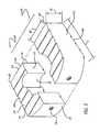
- FIG. 5is a rear perspective view of the implants of FIG. 4 .
- FIG. 6is a top plan view of one of the implants of FIG. 5 .
- FIG. 7is an exterior side elevation view of the implant of FIG. 6 .
- FIG. 8is an interior side elevation view of the implant of FIG. 6 .
- FIG. 9is a leading end view of the implant of FIG. 6 .
- FIG. 10is a trailing end view of the implant of FIG. 6 .
- FIG. 11is a top plan view of another preferred embodiment of a bone implant in accordance with the present invention and a second bone implant that is a mirror image thereof illustrated in dashed line, both implants being shown implanted from an anterior approach to the spine in a vertebral body illustrated in dashed line.
- FIG. 12is a top plan view of another preferred embodiment of a bone implant in accordance with the present invention and a second bone implant that is a mirror image thereof illustrated in dashed line, both implants being shown implanted from a posterior approach to the spine in a vertebral body illustrated in dashed line.
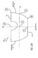
- FIG. 13Ais a top plan view of another preferred embodiment of a bone implant in accordance with the present invention and a second bone implant that is a mirror image thereof illustrated in dashed line, both implants being shown implanted from an anterior approach to the spine in a vertebral body illustrated in dashed line.
- FIG. 13Bis a top plan view of the implant of FIG. 13A illustrating the mid-longitudinal axis and a plane bisecting the mid-longitudinal axis along the length of the implant.
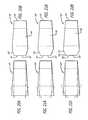
- FIG. 14is a top plan view of another preferred embodiment of a bone implant in accordance with the present invention and a second bone implant that is a mirror image thereof illustrated in dashed line, both implants being shown implanted from an anterior approach to the spine in a vertebral body illustrated in dashed line.
- FIG. 15is a top plan view of another preferred embodiment of a bone implant in accordance with the present invention and a second bone implant that is a mirror image thereof illustrated in dashed line, both implants being shown implanted from a posterior approach to the spine in a vertebral body illustrated in dashed line.
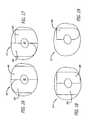
- FIG. 16is a top plan view of a section of diaphyseal bone ring cut across the longitudinal axis of a long bone illustrating the shapes of two implants that can be formed therefrom in accordance with a preferred embodiment of the present invention.
- FIG. 17is a top plan view of a section of diaphyseal bone ring cut across the longitudinal axis of a long bone illustrating the shapes of two implants that can be formed therefrom in accordance with another preferred embodiment of the present invention.
- FIG. 18is a top plan view of a section of diaphyseal bone ring cut across the longitudinal axis of a long bone illustrating the shapes of two implants that can be formed therefrom in accordance with another preferred embodiment of the present invention.
- FIG. 19is a top plan view of a section of diaphyseal bone ring cut across the longitudinal axis of a long bone illustrating the shape of an implant that can be formed therefrom in accordance with another preferred embodiment of the present invention.
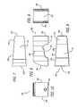
- FIG. 20Ais a side elevation view of a section of diaphyseal bone cut across the longitudinal axis of a long bone illustrating a method of forming a shape of an implant in accordance with a preferred embodiment of the present invention.
- FIG. 20Bis a side elevation view of an implant in accordance with a preferred embodiment of the present invention formed by the method of FIG. 20A .
- FIG. 21Ais a side elevation view of a section of diaphyseal bone cut across the longitudinal axis of a long bone illustrating a method of forming a shape of an implant in accordance with another preferred embodiment of the present invention.
- FIG. 21Bis a side elevation view of an implant in accordance with another preferred embodiment of the present invention formed by the method of FIG. 21A .
- FIG. 22Ais a side elevation view of a section of diaphyseal bone cut across the longitudinal axis of a long bone illustrating a method of forming a shape of an implant in accordance with another preferred embodiment of the present invention.
- FIG. 22Bis a side elevation view of an implant in accordance with another preferred embodiment of the present invention formed by the method of FIG. 22A .
- FIGS. 2 and 3show a preferred method for obtaining a diaphyseal bone ring 50 from a major long bone used to form certain of the implants of the present invention.
- Bone ring 50is formed by making two spaced apart cuts approximately perpendicular to the long axis of the diaphyseal portion of a major long bone with a portion of the medullary canal forming an opening through the ring.
- Such ringsare generally harvested from femurs for use in the lumbar spine.
- Other bones from the arm or leg or other part of the human skeletonmay be useful in various regions of the spine.
- the cutsmay be made into the long bone generally perpendicular to or at other angles transverse to the long axis of the diaphyseal bone to form bone ring 50 having upper and lower surfaces. Making the cuts at an angle to each other creates a bone ring with upper and lower surfaces that are angled relative to each other.
- the angular relationship of the upper and lower surface of the bone ringwhen subsequently formed into an implant and implanted into the spine, positions the adjacent vertebral bodies in angular relationship to each other to restore the natural curvature of the spine, such as lordosis for example.
- bone ring 50has an end 52 with a height that is greater than the height at an end 54 .
- Bone ring 50also has a medullary canal 60 therethrough, shown in outline.
- bone ring 50may be cut into two parts, each part including at least a portion of the medullary canal. Thereafter, the parts are machined to form a desired shape suitable for their intended use as an interbody spinal implant. Examples of tools which may be used to machine the implant include, but are not limited to, burrs, reamers, mills, saws, trephines, chisels, and the like.
- Each part of the bonemay be machined to form an implant having a leading end.
- the leading endmay be shaped to be asymmetrical from side to side and/or may have a straight portion from side to side at the leading end.
- the interior sideincludes at least a portion of the medullary canal and may be machined to be at least in part straight.
- the exterior sidealso may be machined to have a straight portion.
- the trailing end of each partmay be machined to any desired shape suitable for the intended purpose and may be shaped to conform to the anatomical contour of the adjacent vertebral bodies between which the implant is adapted to be inserted. Where it is appropriate, it may be desirable to preserve at least a portion of the natural curvature of the perimeter of the bone ring as part of the configuration of the implant shape.
- FIGS. 4-10show an implant 100 in accordance with a preferred embodiment of the present invention adapted for use from an anterior approach to the spine.
- Implant 100has a leading end 102 for insertion first into the disc space between two adjacent vertebral bodies and a trailing end 104 opposite leading end 102 .
- Implant 100has an upper portion 106 , a lower portion 108 , an interior side 110 , and an exterior facing side 112 opposite interior facing side 110 .
- the phrase “interior side”describes the side of the implant adapted to be orientated toward the interior side of another implant when a pair of implants are inserted side by side into the disc space.
- Interior side 110includes at least a portion of the medullary canal of the bone ring.
- FIG. 4shows a top plan view of a vertebral body V and implants 100 and 100 ′, respectively, inserted from an anterior approach to the spine.
- Implant 100 ′is preferably, but need not be, a mirror image of implant 100 .
- the description of implant 100is equally applicable to implant 100 ′.
- Implant 100is placed side by side with implant 100 ′ so that the portions of the medullary canal of interior sides 110 of each implant are positioned adjacent one another to form a passage 114 therethrough.
- passage 114is adapted to hold bone growth promoting material to permit for the growth of bone from vertebral body to vertebral body through passage 114 .
- the combined width of both implantsis greater than one-half the width of the adjacent vertebral bodies into which the implants are adapted to be inserted.
- leading end 102 and opposed sides 110 , 112are machined to have various configurations.
- Leading end 102can be machined to have a generally planar configuration across at least a portion of its width from side to side.
- leading end 102is preferably machined to have a generally straight portion 116 from side to side that is preferably oriented at approximately 90° to the mid-longitudinal axis of the implant.
- straight portion 116may be adapted to abut that portion of the implantation space.
- Interior side 110is preferably machined to form a corner 118 with generally straight portion 116 of leading end 102 .
- Exterior side 112may be machined to form a corner 120 with generally straight portion 116 of leading end 102 or implant 100 may be machined to have a curved transition from straight portion 116 of leading end 102 to exterior side 112 .
- corners 118 , 120can be machined so either or both of sides 110 , 112 are at a 90° angle to straight portion 116 of leading end 102 to produce at least in part straight portions outwardly facing and at least in part generally parallel to each other, that can be aligned or offset from each other along sides 110 , 112 .
- One or both of sides 110 , 112may also be formed to be at least in part oriented generally parallel to the mid-longitudinal axis of implant 100 .
- leading end 102may be tapered to facilitate insertion of implant 100 between the two adjacent vertebral bodies.
- An example of an implantation space adapted to receive at least a portion of implant 100may be preferably formed with the apparatus and method described by Michelson in U.S. Pat. Nos. 6,159,214 and 6,224,607, the disclosures of which are incorporated herein by reference.
- the instruments and methodare not the subject matter of this application. It is understood that the preparation of the implantation space shown therein are a preferred instrument and method of preparing the implantation spaces and that any method and instrumentation suitable for the purpose may be utilized to prepare the desired implantation space.
- trailing end 104preferably has an asymmetrical curvature from side to side, at least a portion of which is preferably adapted to conform to at least a portion of the peripheral contour of the anterior aspect of the vertebral bodies adjacent the disc space into which the implant is inserted.
- FIGS. 5 and 10show that implant 100 preferably has a driver opening 122 at trailing end 104 for cooperatively engaging an instrument for installing implant 100 into the implantation space.
- Driver opening 122is preferably configured for threaded engagement with an insertion instrument.
- FIGS. 5 , 7 , and 8show at least a portion of upper and lower surfaces 106 , 108 in an angular relationship to each other from trailing end 104 to leading end 102 for allowing for angulation of the adjacent vertebral bodies relative to each other.
- upper and lower surfaces 106 , 108are non-arcuate in a direction along the longitudinal axis of implant 100 .
- upper and lower surfaces 106 , 108may include at least one opening in communication with one another to permit for the growth of bone from vertebral body to vertebral body through implant 100 , though the invention is not so limited.
- Upper and lower surfaces 106 , 108may also be porous and may include a bone ingrowth surface.
- the implants described hereinmay include a bone-engaging surface 124 .
- Bone engaging surface 124preferably has forward facing ratchets 126 facing leading end 102 of implant 100 . Forward facing ratchets 126 resist motion of implant 100 in a direction opposite to the direction of insertion.
- Other preferred embodiments of bone-engaging surfacesmay include the surfaces of the implant being roughened, knurled, splined, or may include at least one protrusion to penetrably engage the bone of the vertebral bodies.
- the implants of the present inventionmay include the surface configuration taught by Michelson in U.S. patent application Ser. No. 09/457,228, entitled “Spinal Implant Surface Configuration,” the disclosure of which is incorporated by reference herein.
- Implant 100is preferably manufactured from a bone ring 50 and includes approximately 40 percent or more of the bone ring from which it is formed. Implant 100 preferably has a length L greater than one-half the depth of the vertebral bodies adjacent the disc space into which the implant is adapted to be inserted as measured between the anterior and posterior aspects of the vertebral bodies. Implant 100 also preferably has a maximum width W that is less than approximately one-half the width of the adjacent vertebral bodies into which the implant is adapted to be inserted.
- the implantinstead of being machined from a single bone portion such as bone ring 50 , the implant can be manufactured from a composite bone material which may include at least one of cortical bone fibers, bone filaments, bone particles, or bone dust, and a material which may or may not be bioactive and/or bioresorbable such as a plastic, ceramic, for example.
- a composite bone materialwhich may include at least one of cortical bone fibers, bone filaments, bone particles, or bone dust, and a material which may or may not be bioactive and/or bioresorbable such as a plastic, ceramic, for example.
- bioresorbable materialsmay include polygalactone.
- FIG. 11shows an implant 200 in accordance with another preferred embodiment of the present invention adapted for use from an anterior approach to the spine.
- Implant 200is similar to implant 100 , except that it has a trailing end 204 that is curved from side to side.
- trailing end 204may be configured in the shape of a half circle from side to side or may be an arc of a circle. Such a configuration of trailing end does not significantly protrude from the disc space between the vertebral bodies and interfere with any delicate neurostructures or vessels that may be present adjacent thereto.
- FIG. 12shows an implant 300 in accordance with another preferred embodiment of the present invention adapted for use from a posterior approach to the spine.
- Implant 300is similar to implant 100 and has a curved transition from straight portion 316 of leading end 302 to exterior side 312 to form a rounded portion 320 .
- Trailing end 304is at least in part straight and can form a corner with exterior side 312 .
- Trailing end 304may have other configurations suitable for its intended purpose.
- FIGS. 13A and 13Bshow an implant 400 in accordance with another preferred embodiment of the present invention adapted for use from an anterior approach to the spine.
- Implant 400has a leading end 402 that is asymmetrical from side to side.
- An example of an implant having an asymmetric leading endis disclosed by Michelson in U.S. Pat. No. 6,350,282, incorporated by reference herein.
- implant 400has a mid-longitudinal axis MLA along its length.
- Mid-longitudinal axis MLAis shown bisected by a plane BPP perpendicular to and bisecting the length of implant 400 along the mid-longitudinal axis MLA.
- Implant 400has a first distance as measured from point C at leading end 402 to plane BPP at point E that is greater than a second distance as measured from plane BPP at point F to the junction of leading end 402 and exterior side 412 at point B.
- Implant 400has a third distance as measured from point A at the junction of leading end 402 and interior side 410 to plane BPP at point D that is greater than the second distance as measured from at point F to point B.
- the third distance from points A to Dis illustrated as being longer than the first distance from points C to E, the third distance can be equal to or less than the first distance.
- the first distance measured from points C to Eis greater than the second distance measured from points B to F; the third distance measured from points A to D can be less than the first distance measured from points C to E; and the third distance measured from points A to D does not equal the second distance measured from points B to F.
- Implant 400preferably has a trailing end 404 that is asymmetrical from side to side. Trailing end 404 may have other configurations suitable for its intended purpose.
- FIG. 14shows an implant 500 in accordance with another preferred embodiment of the present invention adapted for use from an anterior approach to the spine.
- Implant 500is similar to implant 400 , except that it has a trailing end 504 that is symmetrical side to side.
- trailing end 504may be configured in the shape of a half circle from side to side or may be an arc of a circle.
- FIG. 15shows an implant 600 in accordance with another preferred embodiment of the present invention adapted for use from a posterior approach to the spine.
- Implant 600is similar to implant 400 except that trailing end 604 is at least in part straight.
- FIGS. 16-19each show a top plan view of a section of diaphyseal bone ring 50 cut across the longitudinal axis of the long bone shown in FIG. 2 illustrating various shapes of implants that can be formed therefrom.
- FIG. 16shows bone ring 50 being capable of being machined into implants 400 and 500 described above.
- FIG. 17shows bone ring 50 being capable of being machined into implants 100 and 500 described above.
- FIG. 18shows bone ring 50 being capable of being machined into implants 300 and 600 .
- At least a portion of the medullary canalis preferably included in the interior sides of the implants formed from the bone rings. When possible and where it is desired, at least a portion of the natural curvature of the bone ring is preserved and included in the shape of the implants formed.
- FIG. 19shows bone ring 50 being capable of being machined into a single implant, such as implant 200 . It is appreciated that other configuration of implants may be formed in addition to those shown herein without departing from the scope of the present invention.
- FIGS. 20A-22Bshow side elevation views of the diaphyseal bone ring with different configurations of a chamfered tapered end adapted to facilitate the insertion of an implant having a height greater at its a leading end than at its trailing end from the posterior approach to the spine.
- FIGS. 20A and 20Bshow bone ring 50 ′ in accordance with a preferred embodiment of the present invention having a chamfer 128 at end 52 ′ that is configured to provide a portion 56 ′ of end 52 ′ having a reduced height that is generally equal to the height of end 54 ′. The reduced height facilitates introduction into the disc space.
- FIGS. 21A and 21Bshow bone ring 50 ′′ in accordance with another preferred embodiment of the present invention.
- Bone ring 50 ′′is similar to bone ring 50 ′, except that end 52 ′′ has a chamfer 130 that is cut at a steeper angle than chamfer 128 to provide a portion 58 ′′ of end 52 ′′ that has a height that is generally less than the height of end 54 ′′.
- FIGS. 22A and 22Bshow bone ring 50 ′′′ in accordance with another preferred embodiment of the present invention.
- Bone ring 50 ′′′is similar to bone ring 50 ′′, except that end 52 ′′′ is created by making two cuts at different angles to a mid-longitudinal axis between ends 52 ′′′ and 54 ′′′.
- a first cutis made to form a first chamfer 132 and a second cut is made to form second chamfer 134 .
- a portion 59 ′′′ of end 52 ′′′is formed having a height that is generally less than the height of end 54 ′′′.
- the implantmay include, be made of, treated, coated, filled, used in combination with, or have a hollow or medullary canal for containing artificial or naturally occurring materials and/or substances suitable for implantation in the human spine.
- materials and/or substancesinclude any source of osteogenesis, bone growth promoting materials, bone, bone derived substances or products, demineralized bone matrix, mineralizing proteins, ossifying proteins, bone morphogenetic proteins, hydroxyapatite, genes coding for the production of bone, and bone including, but not limited to, cortical bone.
- the implantcan include at least in part of materials that are bioabsorbable and/or resorbable in the body such as bone and/or bone growth promoting materials.
- the implant of the present inventioncan be formed of a porous material or can be formed of a material that intrinsically participates in the growth of bone from one of adjacent vertebral bodies to the other of adjacent vertebral bodies. Where such implants are for posterior implantation, the trailing ends of such implants may be treated with, coated with, or used in combination with chemical substances to inhibit scar tissue formation in the spinal canal.
- the implant of the present inventionmay be modified, or used in combination with materials to make it antibacterial, such as, but not limited to, electroplating or plasma spraying with silver ions or other substance. At least a portion of the implant may be treated to promote bone ingrowth between the implant and the adjacent vertebral bodies.
- the implant of the present inventionmay be used in combination with a spinal fixation implant such as any object, regardless of material, that can be inserted into any portion of the spine, such as but not limited to interbody spinal implants, structural bone grafts, mesh, cages, spacers, staples, bone screws, plates, rods, tethers of synthetic cords or wires, or other spinal fixation hardware
- a spinal fixation implantsuch as any object, regardless of material, that can be inserted into any portion of the spine, such as but not limited to interbody spinal implants, structural bone grafts, mesh, cages, spacers, staples, bone screws, plates, rods, tethers of synthetic cords or wires, or other spinal fixation hardware
Landscapes
- Health & Medical Sciences (AREA)
- Engineering & Computer Science (AREA)
- Biomedical Technology (AREA)
- Orthopedic Medicine & Surgery (AREA)
- Heart & Thoracic Surgery (AREA)
- Cardiology (AREA)
- Oral & Maxillofacial Surgery (AREA)
- Transplantation (AREA)
- Neurology (AREA)
- Vascular Medicine (AREA)
- Life Sciences & Earth Sciences (AREA)
- Animal Behavior & Ethology (AREA)
- General Health & Medical Sciences (AREA)
- Public Health (AREA)
- Veterinary Medicine (AREA)
- Prostheses (AREA)
Abstract
Description
Claims (18)
Priority Applications (1)
| Application Number | Priority Date | Filing Date | Title |
|---|---|---|---|
| US12/587,196US8137403B2 (en) | 2001-04-02 | 2009-10-02 | Hemi-interbody spinal fusion implants manufactured from a major long bone ring |
Applications Claiming Priority (5)
| Application Number | Priority Date | Filing Date | Title |
|---|---|---|---|
| US28111201P | 2001-04-02 | 2001-04-02 | |
| US28118701P | 2001-04-03 | 2001-04-03 | |
| US10/112,745US6989031B2 (en) | 2001-04-02 | 2002-04-02 | Hemi-interbody spinal implant manufactured from a major long bone ring or a bone composite |
| US11/338,395US7611536B2 (en) | 2001-04-02 | 2006-01-24 | Hemi-interbody spinal fusion implants manufactured from a major long bone ring |
| US12/587,196US8137403B2 (en) | 2001-04-02 | 2009-10-02 | Hemi-interbody spinal fusion implants manufactured from a major long bone ring |
Related Parent Applications (1)
| Application Number | Title | Priority Date | Filing Date |
|---|---|---|---|
| US11/338,395ContinuationUS7611536B2 (en) | 2001-04-02 | 2006-01-24 | Hemi-interbody spinal fusion implants manufactured from a major long bone ring |
Publications (2)
| Publication Number | Publication Date |
|---|---|
| US20100030333A1 US20100030333A1 (en) | 2010-02-04 |
| US8137403B2true US8137403B2 (en) | 2012-03-20 |
Family
ID=27381226
Family Applications (3)
| Application Number | Title | Priority Date | Filing Date |
|---|---|---|---|
| US10/112,745Expired - LifetimeUS6989031B2 (en) | 2001-04-02 | 2002-04-02 | Hemi-interbody spinal implant manufactured from a major long bone ring or a bone composite |
| US11/338,395Expired - Fee RelatedUS7611536B2 (en) | 2001-04-02 | 2006-01-24 | Hemi-interbody spinal fusion implants manufactured from a major long bone ring |
| US12/587,196Expired - Fee RelatedUS8137403B2 (en) | 2001-04-02 | 2009-10-02 | Hemi-interbody spinal fusion implants manufactured from a major long bone ring |
Family Applications Before (2)
| Application Number | Title | Priority Date | Filing Date |
|---|---|---|---|
| US10/112,745Expired - LifetimeUS6989031B2 (en) | 2001-04-02 | 2002-04-02 | Hemi-interbody spinal implant manufactured from a major long bone ring or a bone composite |
| US11/338,395Expired - Fee RelatedUS7611536B2 (en) | 2001-04-02 | 2006-01-24 | Hemi-interbody spinal fusion implants manufactured from a major long bone ring |
Country Status (1)
| Country | Link |
|---|---|
| US (3) | US6989031B2 (en) |
Cited By (25)
| Publication number | Priority date | Publication date | Assignee | Title |
|---|---|---|---|---|
| US8834569B2 (en) | 2000-04-19 | 2014-09-16 | Warsaw Orthopedic, Inc. | Artificial hemi-lumbar interbody spinal fusion cage having an asymmetrical leading end |
| WO2016057747A1 (en)* | 2014-10-08 | 2016-04-14 | Globus Medical, Inc. | Standalone interbody implants |
| US9463264B2 (en) | 2014-02-11 | 2016-10-11 | Globus Medical, Inc. | Bone grafts and methods of making and using bone grafts |
| US9463098B2 (en) | 2001-04-02 | 2016-10-11 | Warsaw Orthopedic, Inc. | Spinal fusion implant with bone screws and a bone screw lock |
| US9486483B2 (en) | 2013-10-18 | 2016-11-08 | Globus Medical, Inc. | Bone grafts including osteogenic stem cells, and methods relating to the same |
| US9486327B2 (en) | 2014-05-15 | 2016-11-08 | Globus Medical, Inc. | Standalone interbody implants |
| US9539286B2 (en) | 2013-10-18 | 2017-01-10 | Globus Medical, Inc. | Bone grafts including osteogenic stem cells, and methods relating to the same |
| US9545320B2 (en) | 2014-05-15 | 2017-01-17 | Globus Medical, Inc. | Standalone interbody implants |
| US9579421B2 (en) | 2014-02-07 | 2017-02-28 | Globus Medical Inc. | Bone grafts and methods of making and using bone grafts |
| US9585764B2 (en)* | 2012-07-26 | 2017-03-07 | Warsaw Orthopedic, Inc. | Bone implant device |
| US9730802B1 (en) | 2014-01-14 | 2017-08-15 | Nuvasive, Inc. | Spinal fusion implant and related methods |
| US9795492B1 (en)* | 2012-04-30 | 2017-10-24 | Nuvasive, Inc. | Magnetically connectable interbody spinal implant devices |
| US9968461B2 (en) | 2014-05-15 | 2018-05-15 | Globus Medical, Inc. | Standalone interbody implants |
| US10016529B2 (en) | 2015-06-10 | 2018-07-10 | Globus Medical, Inc. | Biomaterial compositions, implants, and methods of making the same |
| US10130678B2 (en) | 2014-12-29 | 2018-11-20 | Bioventus, LLC. | Systems and methods for improved delivery of osteoinductive molecules in bone repair |
| US10207027B2 (en) | 2012-06-11 | 2019-02-19 | Globus Medical, Inc. | Bioactive bone graft substitutes |
| US10478313B1 (en) | 2014-01-10 | 2019-11-19 | Nuvasive, Inc. | Spinal fusion implant and related methods |
| US10531957B2 (en) | 2015-05-21 | 2020-01-14 | Musculoskeletal Transplant Foundation | Modified demineralized cortical bone fibers |
| US11160666B2 (en) | 2014-05-15 | 2021-11-02 | Globus Medical, Inc. | Laterally insertable intervertebral spinal implant |
| US11298244B2 (en) | 2019-01-31 | 2022-04-12 | K2M, Inc. | Interbody implants and instrumentation |
| US11426489B2 (en) | 2015-06-10 | 2022-08-30 | Globus Medical, Inc. | Biomaterial compositions, implants, and methods of making the same |
| US11534307B2 (en) | 2019-09-16 | 2022-12-27 | K2M, Inc. | 3D printed cervical standalone implant |
| US11896736B2 (en) | 2020-07-13 | 2024-02-13 | Globus Medical, Inc | Biomaterial implants and methods of making the same |
| US12208194B2 (en) | 2018-06-13 | 2025-01-28 | Stryker European Operations Limited | Bone fragment collector and processor |
| US12274629B2 (en) | 2019-12-18 | 2025-04-15 | Stryker European Operations Limited | Bone fragment collector and processor |
Families Citing this family (87)
| Publication number | Priority date | Publication date | Assignee | Title |
|---|---|---|---|---|
| US5609635A (en)* | 1988-06-28 | 1997-03-11 | Michelson; Gary K. | Lordotic interbody spinal fusion implants |
| US6206922B1 (en)* | 1995-03-27 | 2001-03-27 | Sdgi Holdings, Inc. | Methods and instruments for interbody fusion |
| US6033438A (en)* | 1997-06-03 | 2000-03-07 | Sdgi Holdings, Inc. | Open intervertebral spacer |
| US6174311B1 (en)* | 1998-10-28 | 2001-01-16 | Sdgi Holdings, Inc. | Interbody fusion grafts and instrumentation |
| US6241770B1 (en)* | 1999-03-05 | 2001-06-05 | Gary K. Michelson | Interbody spinal fusion implant having an anatomically conformed trailing end |
| CA2363254C (en)* | 1999-03-07 | 2009-05-05 | Discure Ltd. | Method and apparatus for computerized surgery |
| EP1198208B1 (en)* | 1999-05-05 | 2013-07-10 | Warsaw Orthopedic, Inc. | Nested interbody spinal fusion implants |
| US7717961B2 (en)* | 1999-08-18 | 2010-05-18 | Intrinsic Therapeutics, Inc. | Apparatus delivery in an intervertebral disc |
| US7094258B2 (en)* | 1999-08-18 | 2006-08-22 | Intrinsic Therapeutics, Inc. | Methods of reinforcing an annulus fibrosis |
| US7998213B2 (en)* | 1999-08-18 | 2011-08-16 | Intrinsic Therapeutics, Inc. | Intervertebral disc herniation repair |
| CA2425951C (en)* | 1999-08-18 | 2008-09-16 | Intrinsic Therapeutics, Inc. | Devices and method for nucleus pulposus augmentation and retention |
| US8323341B2 (en) | 2007-09-07 | 2012-12-04 | Intrinsic Therapeutics, Inc. | Impaction grafting for vertebral fusion |
| EP1624832A4 (en)* | 1999-08-18 | 2008-12-24 | Intrinsic Therapeutics Inc | Devices and method for augmenting a vertebral disc nucleus |
| US7972337B2 (en) | 2005-12-28 | 2011-07-05 | Intrinsic Therapeutics, Inc. | Devices and methods for bone anchoring |
| US6350283B1 (en)* | 2000-04-19 | 2002-02-26 | Gary K. Michelson | Bone hemi-lumbar interbody spinal implant having an asymmetrical leading end and method of installation thereof |
| AU2001274821A1 (en)* | 2000-06-13 | 2001-12-24 | Gary K. Michelson | Manufactured major long bone ring implant shaped to conform to a prepared intervertebral implantation space |
| US20020111680A1 (en)* | 2000-06-13 | 2002-08-15 | Michelson Gary K. | Ratcheted bone dowel |
| US6749636B2 (en)* | 2001-04-02 | 2004-06-15 | Gary K. Michelson | Contoured spinal fusion implants made of bone or a bone composite material |
| US6989031B2 (en)* | 2001-04-02 | 2006-01-24 | Sdgi Holdings, Inc. | Hemi-interbody spinal implant manufactured from a major long bone ring or a bone composite |
| EP1417000B1 (en) | 2001-07-11 | 2018-07-11 | Nuvasive, Inc. | System for determining nerve proximity during surgery |
| US6471725B1 (en)* | 2001-07-16 | 2002-10-29 | Third Millenium Engineering, Llc | Porous intervertebral distraction spacers |
| JP2005503857A (en) | 2001-09-25 | 2005-02-10 | ヌバシブ, インコーポレイテッド | Systems and methods for performing surgical procedures and surgical diagnosis |
| US7582058B1 (en) | 2002-06-26 | 2009-09-01 | Nuvasive, Inc. | Surgical access system and related methods |
| US8137284B2 (en) | 2002-10-08 | 2012-03-20 | Nuvasive, Inc. | Surgical access system and related methods |
| US7691057B2 (en) | 2003-01-16 | 2010-04-06 | Nuvasive, Inc. | Surgical access system and related methods |
| US7905840B2 (en) | 2003-10-17 | 2011-03-15 | Nuvasive, Inc. | Surgical access system and related methods |
| JP4463819B2 (en) | 2003-09-25 | 2010-05-19 | ヌヴァシヴ インコーポレイテッド | Surgical access system |
| US7918891B1 (en)* | 2004-03-29 | 2011-04-05 | Nuvasive Inc. | Systems and methods for spinal fusion |
| US7648520B2 (en)* | 2004-04-16 | 2010-01-19 | Kyphon Sarl | Pedicle screw assembly |
| WO2006066228A2 (en)* | 2004-12-16 | 2006-06-22 | Innovative Spinal Technologies | Expandable implants for spinal disc replacement |
| US7736380B2 (en)* | 2004-12-21 | 2010-06-15 | Rhausler, Inc. | Cervical plate system |
| USD530423S1 (en) | 2005-03-29 | 2006-10-17 | Nuvasive, Inc. | Intervertebral implant |
| US8147521B1 (en) | 2005-07-20 | 2012-04-03 | Nuvasive, Inc. | Systems and methods for treating spinal deformities |
| US8328851B2 (en) | 2005-07-28 | 2012-12-11 | Nuvasive, Inc. | Total disc replacement system and related methods |
| USD533277S1 (en)* | 2005-11-04 | 2006-12-05 | Quantum Orthopedics, Inc. | Interbody fusion device |
| US20100093829A1 (en)* | 2006-07-07 | 2010-04-15 | Gorman James R | Methods for preventing, postponing or improving the outcome of spinal device and fusion procedures |
| US20080039942A1 (en)* | 2006-08-11 | 2008-02-14 | Bergeron Brian J | Spinal implant |
| US8506636B2 (en) | 2006-09-08 | 2013-08-13 | Theken Spine, Llc | Offset radius lordosis |
| US20080077150A1 (en)* | 2006-09-22 | 2008-03-27 | Linh Nguyen | Steerable rasp/trial member inserter and method of use |
| US7736470B2 (en)* | 2007-01-25 | 2010-06-15 | Exxonmobil Research And Engineering Company | Coker feed method and apparatus |
| US20080234822A1 (en)* | 2007-01-26 | 2008-09-25 | Tutogen Medical, U.S., Inc. | Method and Apparatus for Stabilization and Fusion of Adjacent Bone Segments |
| USD580551S1 (en)* | 2007-02-01 | 2008-11-11 | Zimmer Spine, Inc. | Spinal implant |
| USD585553S1 (en) | 2007-02-22 | 2009-01-27 | Zimmer Spine, Inc. | Spinal implant |
| US8673005B1 (en) | 2007-03-07 | 2014-03-18 | Nuvasive, Inc. | System and methods for spinal fusion |
| US8273127B2 (en)* | 2007-06-06 | 2012-09-25 | Spinesmith Partners, L.P. | Interbody fusion device and associated methods |
| US20090012620A1 (en)* | 2007-07-06 | 2009-01-08 | Jim Youssef | Implantable Cervical Fusion Device |
| EP2208481B1 (en) | 2007-07-27 | 2016-12-28 | R Tree Innovations, LLC | Inter-Body Implantation System |
| US20110196492A1 (en)* | 2007-09-07 | 2011-08-11 | Intrinsic Therapeutics, Inc. | Bone anchoring systems |
| USD671645S1 (en) | 2007-09-18 | 2012-11-27 | Nuvasive, Inc. | Intervertebral implant |
| US9101491B2 (en) | 2007-12-28 | 2015-08-11 | Nuvasive, Inc. | Spinal surgical implant and related methods |
| US8083796B1 (en) | 2008-02-29 | 2011-12-27 | Nuvasive, Inc. | Implants and methods for spinal fusion |
| USD599019S1 (en) | 2008-03-07 | 2009-08-25 | Nuvasive, Inc. | Spinal fusion implant |
| US8333804B1 (en) | 2008-03-27 | 2012-12-18 | Spinelogik, Inc. | Intervertebral fusion device and method of use |
| US8313528B1 (en) | 2008-03-27 | 2012-11-20 | Spinelogik, Inc. | Intervertebral fusion device and method of use |
| USD621509S1 (en) | 2008-10-15 | 2010-08-10 | Nuvasive, Inc. | Intervertebral implant |
| USD754346S1 (en) | 2009-03-02 | 2016-04-19 | Nuvasive, Inc. | Spinal fusion implant |
| US9687357B2 (en) | 2009-03-12 | 2017-06-27 | Nuvasive, Inc. | Vertebral body replacement |
| US9387090B2 (en) | 2009-03-12 | 2016-07-12 | Nuvasive, Inc. | Vertebral body replacement |
| US9351845B1 (en) | 2009-04-16 | 2016-05-31 | Nuvasive, Inc. | Method and apparatus for performing spine surgery |
| US8287597B1 (en) | 2009-04-16 | 2012-10-16 | Nuvasive, Inc. | Method and apparatus for performing spine surgery |
| USD615653S1 (en)* | 2009-06-05 | 2010-05-11 | Horton Kenneth L | Spinal implant |
| USD623747S1 (en)* | 2009-06-30 | 2010-09-14 | Horton Kenneth L | Spinal implant |
| ES2563172T3 (en)* | 2009-07-09 | 2016-03-11 | R Tree Innovations, Llc | Flexible intersomatic implant |
| US9480511B2 (en) | 2009-12-17 | 2016-11-01 | Engage Medical Holdings, Llc | Blade fixation for ankle fusion and arthroplasty |
| US9427324B1 (en) | 2010-02-22 | 2016-08-30 | Spinelogik, Inc. | Intervertebral fusion device and method of use |
| US8956414B2 (en) | 2010-04-21 | 2015-02-17 | Spinecraft, LLC | Intervertebral body implant, instrument and method |
| US8480747B2 (en) | 2010-08-11 | 2013-07-09 | Warsaw Orthopedic, Inc. | Interbody spinal implants with extravertebral support plates |
| US8753396B1 (en) | 2010-09-13 | 2014-06-17 | Theken Spine, Llc | Intervertebral implant having back-out prevention feature |
| EP2651341B1 (en) | 2010-12-16 | 2017-01-04 | Engage Medical Holdings, LLC | Arthroplasty systems and methods |
| US9358122B2 (en) | 2011-01-07 | 2016-06-07 | K2M, Inc. | Interbody spacer |
| US8454694B2 (en) | 2011-03-03 | 2013-06-04 | Warsaw Orthopedic, Inc. | Interbody device and plate for spinal stabilization and instruments for positioning same |
| US8790406B1 (en) | 2011-04-01 | 2014-07-29 | William D. Smith | Systems and methods for performing spine surgery |
| US9687356B1 (en)* | 2011-10-07 | 2017-06-27 | Nuvasive, Inc. | Spinal fusion implants and related methods |
| US9198765B1 (en) | 2011-10-31 | 2015-12-01 | Nuvasive, Inc. | Expandable spinal fusion implants and related methods |
| US9254130B2 (en) | 2011-11-01 | 2016-02-09 | Hyun Bae | Blade anchor systems for bone fusion |
| USD721808S1 (en) | 2011-11-03 | 2015-01-27 | Nuvasive, Inc. | Intervertebral implant |
| USD675320S1 (en) | 2011-11-03 | 2013-01-29 | Nuvasive, Inc. | Intervertebral implant |
| US10238382B2 (en) | 2012-03-26 | 2019-03-26 | Engage Medical Holdings, Llc | Blade anchor for foot and ankle |
| US9283089B2 (en)* | 2012-04-05 | 2016-03-15 | Warsaw Orthopedic, Inc. | Interbody bone implant device |
| US9095385B2 (en) | 2012-11-21 | 2015-08-04 | K2M, Inc. | Adjustable spinal implant insertion instrument |
| USD745159S1 (en) | 2013-10-10 | 2015-12-08 | Nuvasive, Inc. | Intervertebral implant |
| US10194964B2 (en)* | 2014-11-14 | 2019-02-05 | Warsaw Orthopedic, Inc. | Shaped bone graft materials and methods of use |
| USD858769S1 (en) | 2014-11-20 | 2019-09-03 | Nuvasive, Inc. | Intervertebral implant |
| WO2016172026A1 (en) | 2015-04-20 | 2016-10-27 | The Board Of Regents Of The University Of Texas System | Clec11a is a bone growth agent |
| US10390955B2 (en) | 2016-09-22 | 2019-08-27 | Engage Medical Holdings, Llc | Bone implants |
| US10456272B2 (en) | 2017-03-03 | 2019-10-29 | Engage Uni Llc | Unicompartmental knee arthroplasty |
| US11540928B2 (en) | 2017-03-03 | 2023-01-03 | Engage Uni Llc | Unicompartmental knee arthroplasty |
Citations (168)
| Publication number | Priority date | Publication date | Assignee | Title |
|---|---|---|---|---|
| US2677369A (en) | 1952-03-26 | 1954-05-04 | Fred L Knowles | Apparatus for treatment of the spinal column |
| US3426364A (en) | 1966-08-25 | 1969-02-11 | Colorado State Univ Research F | Prosthetic appliance for replacing one or more natural vertebrae |
| US3848601A (en) | 1972-06-14 | 1974-11-19 | G Ma | Method for interbody fusion of the spine |
| US3867728A (en) | 1971-12-30 | 1975-02-25 | Cutter Lab | Prosthesis for spinal repair |
| US3875595A (en) | 1974-04-15 | 1975-04-08 | Edward C Froning | Intervertebral disc prosthesis and instruments for locating same |
| US3905047A (en) | 1973-06-27 | 1975-09-16 | Posta Jr John J | Implantable ceramic bone prosthesis |
| USD245259S (en) | 1976-01-29 | 1977-08-02 | Zimmer U.S.A. Inc. | Tibial prosthesis |
| US4070514A (en) | 1973-06-05 | 1978-01-24 | The United States Of America As Represented By The United States Department Of Energy | Method of fabricating graphite for use as a skeletal prosthesis and product thereof |
| US4309777A (en) | 1980-11-13 | 1982-01-12 | Patil Arun A | Artificial intervertebral disc |
| US4349921A (en) | 1980-06-13 | 1982-09-21 | Kuntz J David | Intervertebral disc prosthesis |
| EP0077159A1 (en) | 1981-10-14 | 1983-04-20 | Brian Norman Atkins | Vertebrae spreader |
| US4501269A (en) | 1981-12-11 | 1985-02-26 | Washington State University Research Foundation, Inc. | Process for fusing bone joints |
| USRE31865E (en) | 1978-06-21 | 1985-04-16 | Artificial joints, in particular coxo-femoral joints | |
| DE3505567A1 (en) | 1984-11-30 | 1986-06-05 | José Manuel Otero Dr. Vigo Pontevedra Vich | Screw-type surgical implant for cervical bones |
| US4599086A (en) | 1985-06-07 | 1986-07-08 | Doty James R | Spine stabilization device and method |
| US4636217A (en) | 1985-04-23 | 1987-01-13 | Regents Of The University Of Minnesota | Anterior spinal implant |
| US4714469A (en) | 1987-02-26 | 1987-12-22 | Pfizer Hospital Products Group, Inc. | Spinal implant |
| EP0260044A1 (en) | 1986-08-29 | 1988-03-16 | John Anthony Norman Shepperd | Spinal implant |
| US4743256A (en) | 1985-10-04 | 1988-05-10 | Brantigan John W | Surgical prosthetic implant facilitating vertebral interbody fusion and method |
| US4759769A (en) | 1987-02-12 | 1988-07-26 | Health & Research Services Inc. | Artificial spinal disc |
| US4759766A (en) | 1984-09-04 | 1988-07-26 | Humboldt-Universitaet Zu Berlin | Intervertebral disc endoprosthesis |
| EP0179695B1 (en) | 1984-09-26 | 1989-03-29 | Pierre Kehr | Vertebral prosthesis, in particular for cervical vertebrae |
| US4820305A (en) | 1986-11-03 | 1989-04-11 | Harms Juergen | Place holder, in particular for a vertebra body |
| US4834757A (en) | 1987-01-22 | 1989-05-30 | Brantigan John W | Prosthetic implant |
| US4863477A (en) | 1987-05-12 | 1989-09-05 | Monson Gary L | Synthetic intervertebral disc prosthesis |
| US4877020A (en) | 1984-11-30 | 1989-10-31 | Vich Jose M O | Apparatus for bone graft |
| US4904261A (en) | 1987-08-06 | 1990-02-27 | A. W. Showell (Surgicraft) Limited | Spinal implants |
| US4911718A (en) | 1988-06-10 | 1990-03-27 | University Of Medicine & Dentistry Of N.J. | Functional and biocompatible intervertebral disc spacer |
| US4936848A (en) | 1989-09-22 | 1990-06-26 | Bagby George W | Implant for vertebrae |
| US4955908A (en) | 1987-07-09 | 1990-09-11 | Sulzer Brothers Limited | Metallic intervertebral prosthesis |
| US4961740A (en) | 1988-10-17 | 1990-10-09 | Surgical Dynamics, Inc. | V-thread fusion cage and method of fusing a bone joint |
| EP0392076A1 (en) | 1989-02-15 | 1990-10-17 | Acromed Corporation | Artificial spinal disc |
| US5015247A (en) | 1988-06-13 | 1991-05-14 | Michelson Gary K | Threaded spinal implant |
| US5015255A (en) | 1989-05-10 | 1991-05-14 | Spine-Tech, Inc. | Spinal stabilization method |
| US5047055A (en) | 1990-12-21 | 1991-09-10 | Pfizer Hospital Products Group, Inc. | Hydrogel intervertebral disc nucleus |
| US5055104A (en) | 1989-11-06 | 1991-10-08 | Surgical Dynamics, Inc. | Surgically implanting threaded fusion cages between adjacent low-back vertebrae by an anterior approach |
| US5059193A (en) | 1989-11-20 | 1991-10-22 | Spine-Tech, Inc. | Expandable spinal implant and surgical method |
| US5122130A (en) | 1988-03-23 | 1992-06-16 | Waldemar Link Gmbh & Co. | Forceps for inserting intervertebral device |
| US5123926A (en) | 1991-02-22 | 1992-06-23 | Madhavan Pisharodi | Artificial spinal prosthesis |
| WO1992014423A1 (en) | 1991-02-22 | 1992-09-03 | Pisharodi Madhavan | Middle expandable intervertebral disk implant and method |
| US5171278A (en) | 1991-02-22 | 1992-12-15 | Madhavan Pisharodi | Middle expandable intervertebral disk implants |
| US5192327A (en) | 1991-03-22 | 1993-03-09 | Brantigan John W | Surgical prosthetic implant for vertebrae |
| US5246458A (en) | 1992-10-07 | 1993-09-21 | Graham Donald V | Artificial disk |
| US5258031A (en) | 1992-01-06 | 1993-11-02 | Danek Medical | Intervertebral disk arthroplasty |
| EP0577179A1 (en) | 1992-06-20 | 1994-01-05 | ESKA Implants GmbH & Co. | An implant for fixing adjacent vertebra |
| US5290312A (en) | 1991-09-03 | 1994-03-01 | Alphatec | Artificial vertebral body |
| US5306309A (en) | 1992-05-04 | 1994-04-26 | Calcitek, Inc. | Spinal disk implant and implantation kit |
| US5306308A (en) | 1989-10-23 | 1994-04-26 | Ulrich Gross | Intervertebral implant |
| EP0599419A3 (en) | 1992-11-26 | 1994-06-29 | Bristol Myers Squibb Co | Disk-shaped implant for reinforcing adjacent vertebrae. |
| US5370697A (en) | 1992-04-21 | 1994-12-06 | Sulzer Medizinaltechnik Ag | Artificial intervertebral disk member |
| EP0627204A2 (en) | 1993-06-04 | 1994-12-07 | ESKA Implants GmbH & Co. | Implant for reinforcing adjacent vertebrae |
| US5397364A (en) | 1993-10-12 | 1995-03-14 | Danek Medical, Inc. | Anterior interbody fusion device |
| US5423855A (en) | 1994-02-15 | 1995-06-13 | Sofamor, S.N.C. | Capped locking clamp for manipulation of surgical implants |
| US5425772A (en) | 1993-09-20 | 1995-06-20 | Brantigan; John W. | Prosthetic implant for intervertebral spinal fusion |
| US5443514A (en) | 1993-10-01 | 1995-08-22 | Acromed Corporation | Method for using spinal implants |
| US5458638A (en) | 1989-07-06 | 1995-10-17 | Spine-Tech, Inc. | Non-threaded spinal implant |
| US5484437A (en) | 1988-06-13 | 1996-01-16 | Michelson; Gary K. | Apparatus and method of inserting spinal implants |
| US5489307A (en) | 1993-02-10 | 1996-02-06 | Spine-Tech, Inc. | Spinal stabilization surgical method |
| US5507813A (en) | 1993-12-09 | 1996-04-16 | Osteotech, Inc. | Shaped materials derived from elongate bone particles |
| US5522899A (en) | 1988-06-28 | 1996-06-04 | Sofamor Danek Properties, Inc. | Artificial spinal fusion implants |
| US5534031A (en) | 1992-01-28 | 1996-07-09 | Asahi Kogaku Kogyo Kabushiki Kaisha | Prosthesis for spanning a space formed upon removal of an intervertebral disk |
| US5571109A (en) | 1993-08-26 | 1996-11-05 | Man Ceramics Gmbh | System for the immobilization of vertebrae |
| WO1996040020A1 (en) | 1995-06-07 | 1996-12-19 | Michelson Gary K | Threaded frusto-conical interbody spinal fusion implants |
| US5593409A (en) | 1988-06-13 | 1997-01-14 | Sofamor Danek Group, Inc. | Interbody spinal fusion implants |
| USD377527S (en) | 1994-06-03 | 1997-01-21 | Sofamor Danek Group, Inc. | Artificial spinal infusion implant |
| US5607424A (en) | 1995-04-10 | 1997-03-04 | Tropiano; Patrick | Domed cage |
| US5609636A (en) | 1994-05-23 | 1997-03-11 | Spine-Tech, Inc. | Spinal implant |
| US5609635A (en) | 1988-06-28 | 1997-03-11 | Michelson; Gary K. | Lordotic interbody spinal fusion implants |
| WO1997023174A1 (en) | 1995-12-21 | 1997-07-03 | Colorado | Interbody-type intervertebral implant |
| WO1997023175A1 (en) | 1995-12-21 | 1997-07-03 | Colorado | Interbody vertebral implant |
| US5645598A (en) | 1996-01-16 | 1997-07-08 | Smith & Nephew, Inc. | Spinal fusion device with porous material |
| US5645084A (en) | 1995-06-07 | 1997-07-08 | Danek Medical, Inc. | Method for spinal fusion without decortication |
| FR2724312B1 (en) | 1995-04-21 | 1997-09-12 | Alby Albert | INTERSOMATIC SPACER |
| US5669909A (en) | 1995-03-27 | 1997-09-23 | Danek Medical, Inc. | Interbody fusion device and method for restoration of normal spinal anatomy |
| EP0637440B1 (en) | 1993-08-06 | 1997-10-15 | Advanced Technical Fabrication | Interbody implant for the spine |
| FR2703580B1 (en) | 1993-03-03 | 1997-10-17 | Gilles Robert | Cervical interbody fusion cage. |
| US5702449A (en) | 1995-06-07 | 1997-12-30 | Danek Medical, Inc. | Reinforced porous spinal implants |
| EP0834295A1 (en) | 1996-10-03 | 1998-04-08 | Medinov-Amp | Vertebral interbody arthrodesis prosthesis |
| US5766252A (en) | 1995-01-24 | 1998-06-16 | Osteonics Corp. | Interbody spinal prosthetic implant and method |
| US5772661A (en) | 1988-06-13 | 1998-06-30 | Michelson; Gary Karlin | Methods and instrumentation for the surgical correction of human thoracic and lumbar spinal disease from the antero-lateral aspect of the spine |
| USD397439S (en) | 1994-07-22 | 1998-08-25 | Tibor Koros | Spinal implant |
| US5800550A (en) | 1996-03-13 | 1998-09-01 | Sertich; Mario M. | Interbody fusion cage |
| US5800547A (en) | 1994-08-20 | 1998-09-01 | Schafer Micomed Gmbh | Ventral intervertebral implant |
| US5814084A (en) | 1996-01-16 | 1998-09-29 | University Of Florida Tissue Bank, Inc. | Diaphysial cortical dowel |
| WO1998044877A1 (en) | 1997-04-07 | 1998-10-15 | Sitiso, Arthit | Intervertebral disk prosthesis and method of making the same |
| FR2761879A1 (en) | 1997-04-11 | 1998-10-16 | Groupe Lepine | Intersomatic cage intervertebral implant |
| WO1998048738A1 (en) | 1997-04-25 | 1998-11-05 | Stryker France S.A. | Two-part intersomatic implant |
| US5846484A (en) | 1997-03-20 | 1998-12-08 | Osteotech, Inc. | Pressure flow system and method for treating a fluid permeable workpiece such as a bone |
| WO1998055052A1 (en) | 1997-06-03 | 1998-12-10 | Sdgi Holdings, Inc. | Open intervertebral spacer |
| US5860973A (en) | 1995-02-27 | 1999-01-19 | Michelson; Gary Karlin | Translateral spinal implant |
| US5865845A (en) | 1996-03-05 | 1999-02-02 | Thalgott; John S. | Prosthetic intervertebral disc |
| US5888222A (en) | 1995-10-16 | 1999-03-30 | Sdgi Holding, Inc. | Intervertebral spacers |
| US5888226A (en) | 1997-11-12 | 1999-03-30 | Rogozinski; Chaim | Intervertebral prosthetic disc |
| US5888227A (en) | 1995-10-20 | 1999-03-30 | Synthes (U.S.A.) | Inter-vertebral implant |
| US5899939A (en) | 1998-01-21 | 1999-05-04 | Osteotech, Inc. | Bone-derived implant for load-supporting applications |
| US5904719A (en) | 1997-07-24 | 1999-05-18 | Techsys Medical, Llc | Interbody fusion device having partial circular section cross-sectional segments |
| US5906635A (en) | 1995-01-23 | 1999-05-25 | Maniglia; Anthony J. | Electromagnetic implantable hearing device for improvement of partial and total sensoryneural hearing loss |
| US5972368A (en) | 1997-06-11 | 1999-10-26 | Sdgi Holdings, Inc. | Bone graft composites and spacers |
| US5989289A (en) | 1995-10-16 | 1999-11-23 | Sdgi Holdings, Inc. | Bone grafts |
| US6034295A (en) | 1995-11-30 | 2000-03-07 | Christoph Rehberg | Implantable device having an internal electrode for stimulating growth of tissue |
| US6037519A (en) | 1997-10-20 | 2000-03-14 | Sdgi Holdings, Inc. | Ceramic fusion implants and compositions |
| US6039762A (en) | 1995-06-07 | 2000-03-21 | Sdgi Holdings, Inc. | Reinforced bone graft substitutes |
| USD425989S (en) | 1996-07-15 | 2000-05-30 | Sofamor Danek Holdings, Inc. | Artificial spinal fusion implant |
| US6080155A (en) | 1988-06-13 | 2000-06-27 | Michelson; Gary Karlin | Method of inserting and preloading spinal implants |
| US6083228A (en) | 1998-06-09 | 2000-07-04 | Michelson; Gary K. | Device and method for preparing a space between adjacent vertebrae to receive an insert |
| US6111164A (en) | 1996-06-21 | 2000-08-29 | Musculoskeletal Transplant Foundation | Bone graft insert |
| US6113638A (en) | 1999-02-26 | 2000-09-05 | Williams; Lytton A. | Method and apparatus for intervertebral implant anchorage |
| US6120503A (en) | 1994-03-28 | 2000-09-19 | Michelson; Gary Karlin | Apparatus instrumentation, and method for spinal fixation |
| US6136031A (en) | 1998-06-17 | 2000-10-24 | Surgical Dynamics, Inc. | Artificial intervertebral disc |
| US6143032A (en) | 1997-11-12 | 2000-11-07 | Schafer Micomed Gmbh | Intervertebral implant |
| US6159214A (en) | 1996-07-31 | 2000-12-12 | Michelson; Gary K. | Milling instrumentation and method for preparing a space between adjacent vertebral bodies |
| US6174311B1 (en)* | 1998-10-28 | 2001-01-16 | Sdgi Holdings, Inc. | Interbody fusion grafts and instrumentation |
| US6179875B1 (en) | 1998-06-17 | 2001-01-30 | Ulrich Gmbh & Co. Kg | Implant for fusing lumbar vertebrae and method of using same |
| US6200347B1 (en) | 1999-01-05 | 2001-03-13 | Lifenet | Composite bone graft, method of making and using same |
| US6206923B1 (en) | 1999-01-08 | 2001-03-27 | Sdgi Holdings, Inc. | Flexible implant using partially demineralized bone |
| US6210412B1 (en) | 1988-06-13 | 2001-04-03 | Gary Karlin Michelson | Method for inserting frusto-conical interbody spinal fusion implants |
| US6224607B1 (en) | 1999-01-25 | 2001-05-01 | Gary K. Michelson | Instrumentation and method for creating an intervertebral space for receiving an implant |
| US6224631B1 (en) | 1998-03-20 | 2001-05-01 | Sulzer Spine-Tech Inc. | Intervertebral implant with reduced contact area and method |
| US6231610B1 (en) | 1999-08-25 | 2001-05-15 | Allegiance Corporation | Anterior cervical column support device |
| US6241770B1 (en) | 1999-03-05 | 2001-06-05 | Gary K. Michelson | Interbody spinal fusion implant having an anatomically conformed trailing end |
| US6241771B1 (en) | 1997-08-13 | 2001-06-05 | Cambridge Scientific, Inc. | Resorbable interbody spinal fusion devices |
| US6245108B1 (en) | 1999-02-25 | 2001-06-12 | Spineco | Spinal fusion implant |
| US6258125B1 (en) | 1998-08-03 | 2001-07-10 | Synthes (U.S.A.) | Intervertebral allograft spacer |
| WO2001049220A1 (en) | 1999-12-30 | 2001-07-12 | Osteotech, Inc. | Intervertebral implants |
| US6270528B1 (en) | 1998-08-06 | 2001-08-07 | Sdgi Holdings, Inc. | Composited intervertebral bone spacers |
| US6277149B1 (en) | 1999-06-08 | 2001-08-21 | Osteotech, Inc. | Ramp-shaped intervertebral implant |
| US20010018614A1 (en) | 1999-03-16 | 2001-08-30 | Bianchi John R. | Implants for orthopedic applications |
| US6294187B1 (en) | 1999-02-23 | 2001-09-25 | Osteotech, Inc. | Load-bearing osteoimplant, method for its manufacture and method of repairing bone using same |
| US6294041B1 (en) | 1998-02-06 | 2001-09-25 | Osteotech, Inc. | Method for an osteoimplant manufacture |
| US20010031254A1 (en) | 1998-11-13 | 2001-10-18 | Bianchi John R. | Assembled implant |
| US6342074B1 (en) | 1999-04-30 | 2002-01-29 | Nathan S. Simpson | Anterior lumbar interbody fusion implant and method for fusing adjacent vertebrae |
| US6348071B1 (en) | 1997-10-31 | 2002-02-19 | Depuy Acromed, Inc. | Spinal disc |
| US6350283B1 (en) | 2000-04-19 | 2002-02-26 | Gary K. Michelson | Bone hemi-lumbar interbody spinal implant having an asymmetrical leading end and method of installation thereof |
| US6371988B1 (en) | 1996-10-23 | 2002-04-16 | Sdgi Holdings, Inc. | Bone grafts |
| US6383221B1 (en) | 1999-01-22 | 2002-05-07 | Osteotech, Inc. | Method for forming an intervertebral implant |
| US6395031B1 (en) | 1998-10-29 | 2002-05-28 | Sdgi Holdings, Inc. | Expandable intervertebral spacers |
| US6402785B1 (en) | 1999-06-04 | 2002-06-11 | Sdgi Holdings, Inc. | Artificial disc implant |
| US20020091447A1 (en) | 2000-11-03 | 2002-07-11 | Osteotech, Inc. | Spinal intervertebral implant and method of making |
| US6423095B1 (en) | 1995-10-16 | 2002-07-23 | Sdgi Holdings, Inc. | Intervertebral spacers |
| US20020099444A1 (en) | 2001-01-22 | 2002-07-25 | Boyd Lawrence M. | Modular interbody fusion implant |
| US20020107571A1 (en) | 2001-02-06 | 2002-08-08 | Foley Kevin T. | Spinal bone implant |
| US20020116065A1 (en) | 1998-10-21 | 2002-08-22 | Jackson Roger P. | Spinal fusion apparatus and method |
| US20020116064A1 (en) | 2001-02-21 | 2002-08-22 | Lance Middleton | Apparatus for fusing adjacent bone structures |
| US6471724B2 (en) | 1995-03-27 | 2002-10-29 | Sdgi Holdings, Inc. | Methods and instruments for interbody fusion |
| US6482233B1 (en) | 1998-01-29 | 2002-11-19 | Synthes(U.S.A.) | Prosthetic interbody spacer |
| US6482584B1 (en) | 1998-11-13 | 2002-11-19 | Regeneration Technologies, Inc. | Cyclic implant perfusion cleaning and passivation process |
| US6485517B1 (en) | 1999-05-05 | 2002-11-26 | Gary K. Michelson | Nested interbody spinal fusion implants |
| US20020193881A1 (en) | 1999-02-04 | 2002-12-19 | Shapiro David E. | Interbody fusion device with anti-rotation features |
| US6511509B1 (en) | 1997-10-20 | 2003-01-28 | Lifenet | Textured bone allograft, method of making and using same |
| US20030028249A1 (en) | 1999-10-18 | 2003-02-06 | Stryker Spine | Intervertebral implant with toothed faces |
| US20030083748A1 (en) | 2001-10-30 | 2003-05-01 | Lee Chong Suh | Intervertebral fusion cage |
| US6562072B1 (en) | 1998-01-23 | 2003-05-13 | Aesculap Ag & Co. Kg | Implant for insertion between spinal column vertebrae |
| US6572654B1 (en) | 2000-10-04 | 2003-06-03 | Albert N. Santilli | Intervertebral spacer |
| US6575981B1 (en) | 1999-02-04 | 2003-06-10 | Sdgi Holdings, Inc. | Methods and instrumentation for vertebral interbody fusion |
| US6629998B1 (en) | 2000-08-23 | 2003-10-07 | Chih-I Lin | Intervertebral retrieval device |
| US6635086B2 (en) | 2000-05-30 | 2003-10-21 | Blacksheep Technologies Incorporated | Implant for placement between cervical vertebrae |
| US6749636B2 (en) | 2001-04-02 | 2004-06-15 | Gary K. Michelson | Contoured spinal fusion implants made of bone or a bone composite material |
| US6808585B2 (en) | 2000-07-03 | 2004-10-26 | Osteotech, Inc. | Osteogenic implants derived from bone |
| US6827740B1 (en) | 1999-12-08 | 2004-12-07 | Gary K. Michelson | Spinal implant surface configuration |
| US6890355B2 (en) | 2001-04-02 | 2005-05-10 | Gary K. Michelson | Artificial contoured spinal fusion implants made of a material other than bone |
| US6923810B1 (en) | 1988-06-13 | 2005-08-02 | Gary Karlin Michelson | Frusto-conical interbody spinal fusion implants |
| US6984245B2 (en) | 2000-02-22 | 2006-01-10 | Sdgi Holdings, Inc. | Anterior impacted bone graft and driver instruments |
| US6989031B2 (en) | 2001-04-02 | 2006-01-24 | Sdgi Holdings, Inc. | Hemi-interbody spinal implant manufactured from a major long bone ring or a bone composite |
| US7048762B1 (en)* | 1997-08-27 | 2006-05-23 | Regeneration Technologies, Inc. | Elongated cortical bone implant |
| US7087082B2 (en) | 1998-08-03 | 2006-08-08 | Synthes (Usa) | Bone implants with central chambers |
| US7115146B2 (en) | 2000-03-22 | 2006-10-03 | Boyer Ii Michael L | Multipiece implants formed of bone material |
| US7156875B2 (en) | 2000-04-19 | 2007-01-02 | Warsaw Orthopedic, Inc. | Arcuate artificial hemi-lumbar interbody spinal fusion implant having an asymmetrical leading end |
| US7534265B1 (en) | 1999-01-11 | 2009-05-19 | Warsaw Orthopedic, Inc. | Intervertebral spacers with side wall accessible interior cavity |
Family Cites Families (11)
| Publication number | Priority date | Publication date | Assignee | Title |
|---|---|---|---|---|
| JPS5729348Y2 (en) | 1975-09-08 | 1982-06-26 | ||
| JPH0655213B2 (en) | 1985-12-27 | 1994-07-27 | 京セラ株式会社 | Lumbar spine block |
| JPS62155846U (en) | 1986-03-26 | 1987-10-03 | ||
| US5306307A (en) | 1991-07-22 | 1994-04-26 | Calcitek, Inc. | Spinal disk implant |
| BE1007549A3 (en) | 1993-09-21 | 1995-08-01 | Beckers Louis Francois Charles | Implant. |
| FR2729557B1 (en) | 1995-01-24 | 1999-01-22 | Stryker Corp | INTERSOMATIC CAGE TYPE IMPLANT, AND INSTRUMENTATION AND METHOD FOR ITS INSTALLATION |
| DE69637631D1 (en) | 1996-08-26 | 2008-09-18 | Chromo Res Inc | ARTIFICIAL HERBS CHROMOSOME |
| EP1221914B1 (en) | 1999-10-19 | 2003-09-03 | SDGI Holdings, Inc. | Cutting tool preparation accessory for mounting the implant |
| EP1263353A2 (en) | 2000-03-10 | 2002-12-11 | SDGI Holdings, Inc. | Synthetic reinforced interbody fusion implants |
| DE20004693U1 (en) | 2000-03-14 | 2001-08-30 | Sofamor Danek GmbH, 94469 Deggendorf | Vertebral implant for insertion in an intervertebral space |
| US6409785B1 (en)* | 2000-08-07 | 2002-06-25 | Bha Technologies, Inc. | Cleanable HEPA filter media |
- 2002
- 2002-04-02USUS10/112,745patent/US6989031B2/ennot_activeExpired - Lifetime
- 2006
- 2006-01-24USUS11/338,395patent/US7611536B2/ennot_activeExpired - Fee Related
- 2009
- 2009-10-02USUS12/587,196patent/US8137403B2/ennot_activeExpired - Fee Related
Patent Citations (211)
| Publication number | Priority date | Publication date | Assignee | Title |
|---|---|---|---|---|
| US2677369A (en) | 1952-03-26 | 1954-05-04 | Fred L Knowles | Apparatus for treatment of the spinal column |
| US3426364A (en) | 1966-08-25 | 1969-02-11 | Colorado State Univ Research F | Prosthetic appliance for replacing one or more natural vertebrae |
| US3867728A (en) | 1971-12-30 | 1975-02-25 | Cutter Lab | Prosthesis for spinal repair |
| US3848601A (en) | 1972-06-14 | 1974-11-19 | G Ma | Method for interbody fusion of the spine |
| US4070514A (en) | 1973-06-05 | 1978-01-24 | The United States Of America As Represented By The United States Department Of Energy | Method of fabricating graphite for use as a skeletal prosthesis and product thereof |
| US3905047A (en) | 1973-06-27 | 1975-09-16 | Posta Jr John J | Implantable ceramic bone prosthesis |
| US3875595A (en) | 1974-04-15 | 1975-04-08 | Edward C Froning | Intervertebral disc prosthesis and instruments for locating same |
| USD245259S (en) | 1976-01-29 | 1977-08-02 | Zimmer U.S.A. Inc. | Tibial prosthesis |
| USRE31865E (en) | 1978-06-21 | 1985-04-16 | Artificial joints, in particular coxo-femoral joints | |
| US4349921A (en) | 1980-06-13 | 1982-09-21 | Kuntz J David | Intervertebral disc prosthesis |
| US4309777A (en) | 1980-11-13 | 1982-01-12 | Patil Arun A | Artificial intervertebral disc |
| EP0077159A1 (en) | 1981-10-14 | 1983-04-20 | Brian Norman Atkins | Vertebrae spreader |
| US4501269A (en) | 1981-12-11 | 1985-02-26 | Washington State University Research Foundation, Inc. | Process for fusing bone joints |
| US4759766A (en) | 1984-09-04 | 1988-07-26 | Humboldt-Universitaet Zu Berlin | Intervertebral disc endoprosthesis |
| EP0179695B1 (en) | 1984-09-26 | 1989-03-29 | Pierre Kehr | Vertebral prosthesis, in particular for cervical vertebrae |
| DE3505567A1 (en) | 1984-11-30 | 1986-06-05 | José Manuel Otero Dr. Vigo Pontevedra Vich | Screw-type surgical implant for cervical bones |
| US4877020A (en) | 1984-11-30 | 1989-10-31 | Vich Jose M O | Apparatus for bone graft |
| US4636217A (en) | 1985-04-23 | 1987-01-13 | Regents Of The University Of Minnesota | Anterior spinal implant |
| US4599086A (en) | 1985-06-07 | 1986-07-08 | Doty James R | Spine stabilization device and method |
| US4743256A (en) | 1985-10-04 | 1988-05-10 | Brantigan John W | Surgical prosthetic implant facilitating vertebral interbody fusion and method |
| US4863476A (en) | 1986-08-29 | 1989-09-05 | Shepperd John A N | Spinal implant |
| EP0260044A1 (en) | 1986-08-29 | 1988-03-16 | John Anthony Norman Shepperd | Spinal implant |
| US4820305A (en) | 1986-11-03 | 1989-04-11 | Harms Juergen | Place holder, in particular for a vertebra body |
| US4834757A (en) | 1987-01-22 | 1989-05-30 | Brantigan John W | Prosthetic implant |
| US4878915A (en) | 1987-01-22 | 1989-11-07 | Brantigan John W | Surgical prosthetic implant facilitating vertebral interbody fusion |
| US4759769A (en) | 1987-02-12 | 1988-07-26 | Health & Research Services Inc. | Artificial spinal disc |
| US4714469A (en) | 1987-02-26 | 1987-12-22 | Pfizer Hospital Products Group, Inc. | Spinal implant |
| US4863477A (en) | 1987-05-12 | 1989-09-05 | Monson Gary L | Synthetic intervertebral disc prosthesis |
| US4955908A (en) | 1987-07-09 | 1990-09-11 | Sulzer Brothers Limited | Metallic intervertebral prosthesis |
| US4904261A (en) | 1987-08-06 | 1990-02-27 | A. W. Showell (Surgicraft) Limited | Spinal implants |
| EP0307241B1 (en) | 1987-09-11 | 1992-12-23 | John W. Brantigan | Surgical prosthetic implant |
| US5122130A (en) | 1988-03-23 | 1992-06-16 | Waldemar Link Gmbh & Co. | Forceps for inserting intervertebral device |
| US4911718A (en) | 1988-06-10 | 1990-03-27 | University Of Medicine & Dentistry Of N.J. | Functional and biocompatible intervertebral disc spacer |
| US5484437A (en) | 1988-06-13 | 1996-01-16 | Michelson; Gary K. | Apparatus and method of inserting spinal implants |
| US5015247A (en) | 1988-06-13 | 1991-05-14 | Michelson Gary K | Threaded spinal implant |
| US7534254B1 (en) | 1988-06-13 | 2009-05-19 | Warsaw Orthopedic, Inc. | Threaded frusto-conical interbody spinal fusion implants |
| US5741253A (en) | 1988-06-13 | 1998-04-21 | Michelson; Gary Karlin | Method for inserting spinal implants |
| US5772661A (en) | 1988-06-13 | 1998-06-30 | Michelson; Gary Karlin | Methods and instrumentation for the surgical correction of human thoracic and lumbar spinal disease from the antero-lateral aspect of the spine |
| US6923810B1 (en) | 1988-06-13 | 2005-08-02 | Gary Karlin Michelson | Frusto-conical interbody spinal fusion implants |
| US6210412B1 (en) | 1988-06-13 | 2001-04-03 | Gary Karlin Michelson | Method for inserting frusto-conical interbody spinal fusion implants |
| US5593409A (en) | 1988-06-13 | 1997-01-14 | Sofamor Danek Group, Inc. | Interbody spinal fusion implants |
| US6080155A (en) | 1988-06-13 | 2000-06-27 | Michelson; Gary Karlin | Method of inserting and preloading spinal implants |
| US5609635A (en) | 1988-06-28 | 1997-03-11 | Michelson; Gary K. | Lordotic interbody spinal fusion implants |
| US5776199A (en) | 1988-06-28 | 1998-07-07 | Sofamor Danek Properties | Artificial spinal fusion implants |
| US5522899A (en) | 1988-06-28 | 1996-06-04 | Sofamor Danek Properties, Inc. | Artificial spinal fusion implants |
| US4961740A (en) | 1988-10-17 | 1990-10-09 | Surgical Dynamics, Inc. | V-thread fusion cage and method of fusing a bone joint |
| US4961740B1 (en) | 1988-10-17 | 1997-01-14 | Surgical Dynamics Inc | V-thread fusion cage and method of fusing a bone joint |
| US5026373A (en) | 1988-10-17 | 1991-06-25 | Surgical Dynamics, Inc. | Surgical method and apparatus for fusing adjacent bone structures |
| EP0392076A1 (en) | 1989-02-15 | 1990-10-17 | Acromed Corporation | Artificial spinal disc |
| US5071437A (en) | 1989-02-15 | 1991-12-10 | Acromed Corporation | Artificial disc |
| US5015255A (en) | 1989-05-10 | 1991-05-14 | Spine-Tech, Inc. | Spinal stabilization method |
| US5062845A (en) | 1989-05-10 | 1991-11-05 | Spine-Tech, Inc. | Method of making an intervertebral reamer |
| US5458638A (en) | 1989-07-06 | 1995-10-17 | Spine-Tech, Inc. | Non-threaded spinal implant |
| US6391058B1 (en) | 1989-07-06 | 2002-05-21 | Sulzer Spine-Tech Inc. | Threaded spinal implant with convex trailing surface |
| US4936848A (en) | 1989-09-22 | 1990-06-26 | Bagby George W | Implant for vertebrae |
| US5306308A (en) | 1989-10-23 | 1994-04-26 | Ulrich Gross | Intervertebral implant |
| US5055104A (en) | 1989-11-06 | 1991-10-08 | Surgical Dynamics, Inc. | Surgically implanting threaded fusion cages between adjacent low-back vertebrae by an anterior approach |
| US5059193A (en) | 1989-11-20 | 1991-10-22 | Spine-Tech, Inc. | Expandable spinal implant and surgical method |
| US5047055A (en) | 1990-12-21 | 1991-09-10 | Pfizer Hospital Products Group, Inc. | Hydrogel intervertebral disc nucleus |
| US5171278A (en) | 1991-02-22 | 1992-12-15 | Madhavan Pisharodi | Middle expandable intervertebral disk implants |
| US5123926A (en) | 1991-02-22 | 1992-06-23 | Madhavan Pisharodi | Artificial spinal prosthesis |
| WO1992014423A1 (en) | 1991-02-22 | 1992-09-03 | Pisharodi Madhavan | Middle expandable intervertebral disk implant and method |
| US5192327A (en) | 1991-03-22 | 1993-03-09 | Brantigan John W | Surgical prosthetic implant for vertebrae |
| US5290312A (en) | 1991-09-03 | 1994-03-01 | Alphatec | Artificial vertebral body |
| US5258031A (en) | 1992-01-06 | 1993-11-02 | Danek Medical | Intervertebral disk arthroplasty |
| US5534031A (en) | 1992-01-28 | 1996-07-09 | Asahi Kogaku Kogyo Kabushiki Kaisha | Prosthesis for spanning a space formed upon removal of an intervertebral disk |
| US5370697A (en) | 1992-04-21 | 1994-12-06 | Sulzer Medizinaltechnik Ag | Artificial intervertebral disk member |
| US5306309A (en) | 1992-05-04 | 1994-04-26 | Calcitek, Inc. | Spinal disk implant and implantation kit |
| EP0577179A1 (en) | 1992-06-20 | 1994-01-05 | ESKA Implants GmbH & Co. | An implant for fixing adjacent vertebra |
| US5246458A (en) | 1992-10-07 | 1993-09-21 | Graham Donald V | Artificial disk |
| EP0599419A3 (en) | 1992-11-26 | 1994-06-29 | Bristol Myers Squibb Co | Disk-shaped implant for reinforcing adjacent vertebrae. |
| US5489307A (en) | 1993-02-10 | 1996-02-06 | Spine-Tech, Inc. | Spinal stabilization surgical method |
| FR2703580B1 (en) | 1993-03-03 | 1997-10-17 | Gilles Robert | Cervical interbody fusion cage. |
| EP0627204A2 (en) | 1993-06-04 | 1994-12-07 | ESKA Implants GmbH & Co. | Implant for reinforcing adjacent vertebrae |
| EP0637440B1 (en) | 1993-08-06 | 1997-10-15 | Advanced Technical Fabrication | Interbody implant for the spine |
| US5683463A (en) | 1993-08-06 | 1997-11-04 | Advanced Technical Fabrication | Intersomatic vertebral column implant |
| US5571109A (en) | 1993-08-26 | 1996-11-05 | Man Ceramics Gmbh | System for the immobilization of vertebrae |
| US5425772A (en) | 1993-09-20 | 1995-06-20 | Brantigan; John W. | Prosthetic implant for intervertebral spinal fusion |
| US5443514A (en) | 1993-10-01 | 1995-08-22 | Acromed Corporation | Method for using spinal implants |
| US5397364A (en) | 1993-10-12 | 1995-03-14 | Danek Medical, Inc. | Anterior interbody fusion device |
| US5507813A (en) | 1993-12-09 | 1996-04-16 | Osteotech, Inc. | Shaped materials derived from elongate bone particles |
| US5423855A (en) | 1994-02-15 | 1995-06-13 | Sofamor, S.N.C. | Capped locking clamp for manipulation of surgical implants |
| US6120503A (en) | 1994-03-28 | 2000-09-19 | Michelson; Gary Karlin | Apparatus instrumentation, and method for spinal fixation |
| US5658337A (en) | 1994-05-23 | 1997-08-19 | Spine-Tech, Inc. | Intervertebral fusion implant |
| US5609636A (en) | 1994-05-23 | 1997-03-11 | Spine-Tech, Inc. | Spinal implant |
| USD377527S (en) | 1994-06-03 | 1997-01-21 | Sofamor Danek Group, Inc. | Artificial spinal infusion implant |
| USD397439S (en) | 1994-07-22 | 1998-08-25 | Tibor Koros | Spinal implant |
| US5800547A (en) | 1994-08-20 | 1998-09-01 | Schafer Micomed Gmbh | Ventral intervertebral implant |
| US5906635A (en) | 1995-01-23 | 1999-05-25 | Maniglia; Anthony J. | Electromagnetic implantable hearing device for improvement of partial and total sensoryneural hearing loss |
| US5766252A (en) | 1995-01-24 | 1998-06-16 | Osteonics Corp. | Interbody spinal prosthetic implant and method |
| US5860973A (en) | 1995-02-27 | 1999-01-19 | Michelson; Gary Karlin | Translateral spinal implant |
| US5782919A (en) | 1995-03-27 | 1998-07-21 | Sdgi Holdings, Inc. | Interbody fusion device and method for restoration of normal spinal anatomy |
| US5669909A (en) | 1995-03-27 | 1997-09-23 | Danek Medical, Inc. | Interbody fusion device and method for restoration of normal spinal anatomy |
| US6471724B2 (en) | 1995-03-27 | 2002-10-29 | Sdgi Holdings, Inc. | Methods and instruments for interbody fusion |
| US5607424A (en) | 1995-04-10 | 1997-03-04 | Tropiano; Patrick | Domed cage |
| FR2724312B1 (en) | 1995-04-21 | 1997-09-12 | Alby Albert | INTERSOMATIC SPACER |
| US5702449A (en) | 1995-06-07 | 1997-12-30 | Danek Medical, Inc. | Reinforced porous spinal implants |
| US5645084A (en) | 1995-06-07 | 1997-07-08 | Danek Medical, Inc. | Method for spinal fusion without decortication |
| US6039762A (en) | 1995-06-07 | 2000-03-21 | Sdgi Holdings, Inc. | Reinforced bone graft substitutes |
| WO1996040020A1 (en) | 1995-06-07 | 1996-12-19 | Michelson Gary K | Threaded frusto-conical interbody spinal fusion implants |
| US6423095B1 (en) | 1995-10-16 | 2002-07-23 | Sdgi Holdings, Inc. | Intervertebral spacers |
| US5888222A (en) | 1995-10-16 | 1999-03-30 | Sdgi Holding, Inc. | Intervertebral spacers |
| US5989289A (en) | 1995-10-16 | 1999-11-23 | Sdgi Holdings, Inc. | Bone grafts |
| US5888227A (en) | 1995-10-20 | 1999-03-30 | Synthes (U.S.A.) | Inter-vertebral implant |
| US6034295A (en) | 1995-11-30 | 2000-03-07 | Christoph Rehberg | Implantable device having an internal electrode for stimulating growth of tissue |
| WO1997023175A1 (en) | 1995-12-21 | 1997-07-03 | Colorado | Interbody vertebral implant |
| WO1997023174A1 (en) | 1995-12-21 | 1997-07-03 | Colorado | Interbody-type intervertebral implant |
| US5814084A (en) | 1996-01-16 | 1998-09-29 | University Of Florida Tissue Bank, Inc. | Diaphysial cortical dowel |
| US5645598A (en) | 1996-01-16 | 1997-07-08 | Smith & Nephew, Inc. | Spinal fusion device with porous material |
| US5865845A (en) | 1996-03-05 | 1999-02-02 | Thalgott; John S. | Prosthetic intervertebral disc |
| US5800550A (en) | 1996-03-13 | 1998-09-01 | Sertich; Mario M. | Interbody fusion cage |
| US6111164A (en) | 1996-06-21 | 2000-08-29 | Musculoskeletal Transplant Foundation | Bone graft insert |
| USD425989S (en) | 1996-07-15 | 2000-05-30 | Sofamor Danek Holdings, Inc. | Artificial spinal fusion implant |
| US6159214A (en) | 1996-07-31 | 2000-12-12 | Michelson; Gary K. | Milling instrumentation and method for preparing a space between adjacent vertebral bodies |
| EP0834295A1 (en) | 1996-10-03 | 1998-04-08 | Medinov-Amp | Vertebral interbody arthrodesis prosthesis |
| US6371988B1 (en) | 1996-10-23 | 2002-04-16 | Sdgi Holdings, Inc. | Bone grafts |
| US5846484A (en) | 1997-03-20 | 1998-12-08 | Osteotech, Inc. | Pressure flow system and method for treating a fluid permeable workpiece such as a bone |
| US5861041A (en) | 1997-04-07 | 1999-01-19 | Arthit Sitiso | Intervertebral disk prosthesis and method of making the same |
| WO1998044877A1 (en) | 1997-04-07 | 1998-10-15 | Sitiso, Arthit | Intervertebral disk prosthesis and method of making the same |
| FR2761879A1 (en) | 1997-04-11 | 1998-10-16 | Groupe Lepine | Intersomatic cage intervertebral implant |
| US6855168B2 (en) | 1997-04-25 | 2005-02-15 | Stryker France | Intersomatic implants in two parts |
| WO1998048738A1 (en) | 1997-04-25 | 1998-11-05 | Stryker France S.A. | Two-part intersomatic implant |
| US6033438A (en)* | 1997-06-03 | 2000-03-07 | Sdgi Holdings, Inc. | Open intervertebral spacer |
| US6409765B1 (en) | 1997-06-03 | 2002-06-25 | Sdgi Holdings, Inc. | Open intervertebral spacer |
| WO1998055052A1 (en) | 1997-06-03 | 1998-12-10 | Sdgi Holdings, Inc. | Open intervertebral spacer |
| US6261586B1 (en) | 1997-06-11 | 2001-07-17 | Sdgi Holdings, Inc. | Bone graft composites and spacers |
| US5972368A (en) | 1997-06-11 | 1999-10-26 | Sdgi Holdings, Inc. | Bone graft composites and spacers |
| US5904719A (en) | 1997-07-24 | 1999-05-18 | Techsys Medical, Llc | Interbody fusion device having partial circular section cross-sectional segments |
| US6241771B1 (en) | 1997-08-13 | 2001-06-05 | Cambridge Scientific, Inc. | Resorbable interbody spinal fusion devices |
| US7048762B1 (en)* | 1997-08-27 | 2006-05-23 | Regeneration Technologies, Inc. | Elongated cortical bone implant |
| US6511509B1 (en) | 1997-10-20 | 2003-01-28 | Lifenet | Textured bone allograft, method of making and using same |
| US6037519A (en) | 1997-10-20 | 2000-03-14 | Sdgi Holdings, Inc. | Ceramic fusion implants and compositions |
| US6348071B1 (en) | 1997-10-31 | 2002-02-19 | Depuy Acromed, Inc. | Spinal disc |
| US6143032A (en) | 1997-11-12 | 2000-11-07 | Schafer Micomed Gmbh | Intervertebral implant |
| US5888226A (en) | 1997-11-12 | 1999-03-30 | Rogozinski; Chaim | Intervertebral prosthetic disc |
| US5899939A (en) | 1998-01-21 | 1999-05-04 | Osteotech, Inc. | Bone-derived implant for load-supporting applications |
| US6562072B1 (en) | 1998-01-23 | 2003-05-13 | Aesculap Ag & Co. Kg | Implant for insertion between spinal column vertebrae |
| US6482233B1 (en) | 1998-01-29 | 2002-11-19 | Synthes(U.S.A.) | Prosthetic interbody spacer |
| US6294041B1 (en) | 1998-02-06 | 2001-09-25 | Osteotech, Inc. | Method for an osteoimplant manufacture |
| US6224631B1 (en) | 1998-03-20 | 2001-05-01 | Sulzer Spine-Tech Inc. | Intervertebral implant with reduced contact area and method |
| US6083228A (en) | 1998-06-09 | 2000-07-04 | Michelson; Gary K. | Device and method for preparing a space between adjacent vertebrae to receive an insert |
| US6179875B1 (en) | 1998-06-17 | 2001-01-30 | Ulrich Gmbh & Co. Kg | Implant for fusing lumbar vertebrae and method of using same |
| US6136031A (en) | 1998-06-17 | 2000-10-24 | Surgical Dynamics, Inc. | Artificial intervertebral disc |
| US6258125B1 (en) | 1998-08-03 | 2001-07-10 | Synthes (U.S.A.) | Intervertebral allograft spacer |
| US7087082B2 (en) | 1998-08-03 | 2006-08-08 | Synthes (Usa) | Bone implants with central chambers |
| US6554863B2 (en) | 1998-08-03 | 2003-04-29 | Synthes | Intervertebral allograft spacer |
| US6270528B1 (en) | 1998-08-06 | 2001-08-07 | Sdgi Holdings, Inc. | Composited intervertebral bone spacers |
| US20020116065A1 (en) | 1998-10-21 | 2002-08-22 | Jackson Roger P. | Spinal fusion apparatus and method |
| US7479160B2 (en)* | 1998-10-28 | 2009-01-20 | Warsaw Orthopedic, Inc. | Interbody fusion grafts and instrumentation |
| US6174311B1 (en)* | 1998-10-28 | 2001-01-16 | Sdgi Holdings, Inc. | Interbody fusion grafts and instrumentation |
| US6395031B1 (en) | 1998-10-29 | 2002-05-28 | Sdgi Holdings, Inc. | Expandable intervertebral spacers |
| US20010031254A1 (en) | 1998-11-13 | 2001-10-18 | Bianchi John R. | Assembled implant |
| US6482584B1 (en) | 1998-11-13 | 2002-11-19 | Regeneration Technologies, Inc. | Cyclic implant perfusion cleaning and passivation process |
| US6200347B1 (en) | 1999-01-05 | 2001-03-13 | Lifenet | Composite bone graft, method of making and using same |
| US6206923B1 (en) | 1999-01-08 | 2001-03-27 | Sdgi Holdings, Inc. | Flexible implant using partially demineralized bone |
| US7534265B1 (en) | 1999-01-11 | 2009-05-19 | Warsaw Orthopedic, Inc. | Intervertebral spacers with side wall accessible interior cavity |
| US6383221B1 (en) | 1999-01-22 | 2002-05-07 | Osteotech, Inc. | Method for forming an intervertebral implant |
| US6224607B1 (en) | 1999-01-25 | 2001-05-01 | Gary K. Michelson | Instrumentation and method for creating an intervertebral space for receiving an implant |
| US6575981B1 (en) | 1999-02-04 | 2003-06-10 | Sdgi Holdings, Inc. | Methods and instrumentation for vertebral interbody fusion |
| US20020193881A1 (en) | 1999-02-04 | 2002-12-19 | Shapiro David E. | Interbody fusion device with anti-rotation features |
| US6294187B1 (en) | 1999-02-23 | 2001-09-25 | Osteotech, Inc. | Load-bearing osteoimplant, method for its manufacture and method of repairing bone using same |
| US6245108B1 (en) | 1999-02-25 | 2001-06-12 | Spineco | Spinal fusion implant |
| US6113638A (en) | 1999-02-26 | 2000-09-05 | Williams; Lytton A. | Method and apparatus for intervertebral implant anchorage |
| US20040064185A1 (en) | 1999-03-05 | 2004-04-01 | Michelson Gary K. | Interbody spinal fusion implant having a reduced width and an anatomically conformed trailing end |
| US20010010020A1 (en) | 1999-03-05 | 2001-07-26 | Michelson Gary K. | Interbody spinal fusion implant having an anatomically conformed trailing end |
| US20050216089A1 (en) | 1999-03-05 | 2005-09-29 | Michelson Gary K | Arcuate interbody spinal fusion implant having a reduced width and an anatomically conformed trailing end |
| US6241770B1 (en) | 1999-03-05 | 2001-06-05 | Gary K. Michelson | Interbody spinal fusion implant having an anatomically conformed trailing end |
| US20010018614A1 (en) | 1999-03-16 | 2001-08-30 | Bianchi John R. | Implants for orthopedic applications |
| US6342074B1 (en) | 1999-04-30 | 2002-01-29 | Nathan S. Simpson | Anterior lumbar interbody fusion implant and method for fusing adjacent vertebrae |
| US20100145463A1 (en) | 1999-05-05 | 2010-06-10 | Michelson Gary K | Nested interbody spinal fusion implants |
| US7637951B2 (en) | 1999-05-05 | 2009-12-29 | Warsaw Orthopedic, Inc. | Nested interbody spinal fusion implants |
| US20040210313A1 (en) | 1999-05-05 | 2004-10-21 | Michelson Gary K. | Method for inserting nested interbody spinal fusion implants |
| US7637954B2 (en) | 1999-05-05 | 2009-12-29 | Warsaw Orthopedic, Inc. | Apparatus for inserting nested interbody spinal fusion implants |
| US6485517B1 (en) | 1999-05-05 | 2002-11-26 | Gary K. Michelson | Nested interbody spinal fusion implants |
| US6402785B1 (en) | 1999-06-04 | 2002-06-11 | Sdgi Holdings, Inc. | Artificial disc implant |
| US6530955B2 (en) | 1999-06-08 | 2003-03-11 | Osteotech, Inc. | Ramp-shaped intervertebral implant |
| US6277149B1 (en) | 1999-06-08 | 2001-08-21 | Osteotech, Inc. | Ramp-shaped intervertebral implant |
| US6231610B1 (en) | 1999-08-25 | 2001-05-15 | Allegiance Corporation | Anterior cervical column support device |
| US20030028249A1 (en) | 1999-10-18 | 2003-02-06 | Stryker Spine | Intervertebral implant with toothed faces |
| US6827740B1 (en) | 1999-12-08 | 2004-12-07 | Gary K. Michelson | Spinal implant surface configuration |
| WO2001049220A1 (en) | 1999-12-30 | 2001-07-12 | Osteotech, Inc. | Intervertebral implants |
| US6984245B2 (en) | 2000-02-22 | 2006-01-10 | Sdgi Holdings, Inc. | Anterior impacted bone graft and driver instruments |
| US7115146B2 (en) | 2000-03-22 | 2006-10-03 | Boyer Ii Michael L | Multipiece implants formed of bone material |
| US7462195B1 (en)* | 2000-04-19 | 2008-12-09 | Warsaw Orthopedic, Inc. | Artificial lumbar interbody spinal implant having an asymmetrical leading end |
| US20060235519A1 (en) | 2000-04-19 | 2006-10-19 | Sdgi Holdings, Inc. | Bone hemi-lumbar arcuate interbody spinal fusion implant having an asymmetrical leading end |
| US7156875B2 (en) | 2000-04-19 | 2007-01-02 | Warsaw Orthopedic, Inc. | Arcuate artificial hemi-lumbar interbody spinal fusion implant having an asymmetrical leading end |
| US7387643B2 (en) | 2000-04-19 | 2008-06-17 | Warsaw Orthopedic, Inc. | Method for installation of artificial hemi-lumbar interbody spinal fusion implant having an asymmetrical leading end |
| US6666890B2 (en) | 2000-04-19 | 2003-12-23 | Gary K. Michelson | Bone hemi-lumbar interbody spinal implant having an asymmetrical leading end and method of installation thereof |
| US20090105821A1 (en) | 2000-04-19 | 2009-04-23 | Michelson Gary K | Artificial hemi-lumbar interbody spinal implant having an asymmetrical leading end |
| US6350283B1 (en) | 2000-04-19 | 2002-02-26 | Gary K. Michelson | Bone hemi-lumbar interbody spinal implant having an asymmetrical leading end and method of installation thereof |
| US7022137B2 (en) | 2000-04-19 | 2006-04-04 | Sdgi Holdings, Inc. | Bone hemi-lumbar interbody spinal fusion implant having an asymmetrical leading end and method of installation thereof |
| US6635086B2 (en) | 2000-05-30 | 2003-10-21 | Blacksheep Technologies Incorporated | Implant for placement between cervical vertebrae |
| US6808585B2 (en) | 2000-07-03 | 2004-10-26 | Osteotech, Inc. | Osteogenic implants derived from bone |
| US6629998B1 (en) | 2000-08-23 | 2003-10-07 | Chih-I Lin | Intervertebral retrieval device |
| US6572654B1 (en) | 2000-10-04 | 2003-06-03 | Albert N. Santilli | Intervertebral spacer |
| US6706067B2 (en)* | 2000-11-03 | 2004-03-16 | Osteotech, Inc. | Spinal intervertebral implant and method of making |
| US20020091447A1 (en) | 2000-11-03 | 2002-07-11 | Osteotech, Inc. | Spinal intervertebral implant and method of making |
| US6468311B2 (en) | 2001-01-22 | 2002-10-22 | Sdgi Holdings, Inc. | Modular interbody fusion implant |
| US20020099444A1 (en) | 2001-01-22 | 2002-07-25 | Boyd Lawrence M. | Modular interbody fusion implant |
| US20020107571A1 (en) | 2001-02-06 | 2002-08-08 | Foley Kevin T. | Spinal bone implant |
| US20020116064A1 (en) | 2001-02-21 | 2002-08-22 | Lance Middleton | Apparatus for fusing adjacent bone structures |
| US6749636B2 (en) | 2001-04-02 | 2004-06-15 | Gary K. Michelson | Contoured spinal fusion implants made of bone or a bone composite material |
| US6890355B2 (en) | 2001-04-02 | 2005-05-10 | Gary K. Michelson | Artificial contoured spinal fusion implants made of a material other than bone |
| US7540882B2 (en)* | 2001-04-02 | 2009-06-02 | Warsaw Orthopedic, Inc. | Artificial spinal fusion implant with asymmetrical leading end |
| US20090270991A1 (en) | 2001-04-02 | 2009-10-29 | Sdgi Holdings, Inc. | Spinal fusion implant with bone screws |
| US7611536B2 (en) | 2001-04-02 | 2009-11-03 | Warsaw Orthopedic, Inc. | Hemi-interbody spinal fusion implants manufactured from a major long bone ring |
| US6989031B2 (en) | 2001-04-02 | 2006-01-24 | Sdgi Holdings, Inc. | Hemi-interbody spinal implant manufactured from a major long bone ring or a bone composite |
| US7455692B2 (en)* | 2001-04-02 | 2008-11-25 | Warsaw Orthopedic, Inc. | Hemi-artificial contoured spinal fusion implants made of a material other than bone |
| US7435262B2 (en) | 2001-04-02 | 2008-10-14 | Warsaw Orthopedic, Inc. | Contoured cortical bone implants |
| US20110208313A1 (en) | 2001-04-02 | 2011-08-25 | Michelson Gary K | Spinal fusion implant with bone screws and a bone screw lock |
| US20030083748A1 (en) | 2001-10-30 | 2003-05-01 | Lee Chong Suh | Intervertebral fusion cage |
Non-Patent Citations (30)
| Title |
|---|
| A picture of a Medtronic, Sofamor Danek Display; titled "Evolving With Your Needs;" Apr. 2000. |
| Bagby, G.W.; Arthrodesis by the Distraction-Compression Method Using a Stainless Steel Implant; Orthopedics, vol. II, No. 6, pp. 931-934 (Jun. 1987). |
| Brochure of University of Florida Tissue Bank; MD-I and MD-II Custom Machine Cortical Dowels; Circa 1996. |
| Brochure of University of Florida Tissue Bank; MD-III Threaded Cortical Dowel; Circa 1996. |
| Butts, M.K., et al.; "Biomechanical Analysis of a New Method for Spinal Interbody Fixation;" 1987 Symposium, American Society of Mechanical Engineers, "Advances in Bioengineering", Boston, MA; Dec. 13-18, 1987; 7 pages. |
| Crawley, Gregory R., et al.; "A Modified Cloward's Technique for Arthrodesis of the Normal Metacarpophalangeal Joint in the Horse;" Veterinary Surgery, vol. 17, No. 3; 1988; pp. 117-127. |
| Crock, H.V.; Practice of Spinal Surgery; Springer-Verlag/Wien, New York; 1983. |
| DeBowes, R.M., et al.; Study of Bovine . . . Steel Baskets; Transactions of the 29th Annual Meeting; Orthopedic Research Society, vol. 8, p. 407; Mar. 8-10, 1983. |
| European Opposition Document, Nov. 27, 1995-Opposing EP Patent No. 425 542 B1 Anterior Spinal Fusion Implant; 5 pages. |
| Glazer, P.A., et al.; Biomechanical Analysis of Multilevel Fixation Methods in the Lumbar Spine; Spine, vol. 22, No. 2, pp. 171-182 (1997). |
| International Search Report mailed Aug. 14, 2000 from corresponding International PCT Application No. PCT/US00/12363, filed May 5, 2000; 1 page. |
| International Search Report mailed on Aug. 15, 2001, of corresponding International Application No. PCT/US01/11723, filed Apr. 19, 2001; 3 pages. |
| Introducing graftech Allografts, Webpage by Osteotech; Jan. 2002. |
| Laparoscopic Bone Dowel Instruments; Brochure of Sofamor Danek; 1995; 2 pages. |
| Laparoscopic Bone Dowel Surgical Technique; Brochure of Sofamor Danek; 1995. |
| Muschler, et al.; The Biology of Spinal Fusion; Spinal Fusion Science and Technique, Cotler and Cotler, pp. 9- 13; Dec. 1989. |
| New IBS Allograft, The C-TLIF Approach, Brochure of OrthoDevelopment; 2002. |
| Otero-Vich, Jose M.; Anterior Cervical Interbody Fusion with Threaded Cylinrical Bone; J. Neurosurg 63:750-753; Nov. 1985. |
| Puros ALIF Bone Graft, Brochure by Sulzer Spine-Tech; 2001. |
| Ray, C.D.; Spinal Interbody Fusions: A Review, Featuring New Generation Techniques; Neurosurgery Quarterly, 7(2):135-156; 1997. |
| Roman, M., et al.; Banked Bone grafting for Bone Defect Repair-Clinical Evaluation of Bone Union and Graft Incorporation; J. Jpn. Orthop. Assoc. 62:461-469; 1988. |
| RTI Precision Machined Allograft: The Surgeon's Choice, Brochure by Regeneration Technologies, Inc.; 2000. |
| RTI Tissue Services, Spinal Allograft, Webpage of Regeneration Technologies, Inc.; 2002. |
| Schmitz et al.; Performance of Alloplastic Materials and Design of an Artificial Disc; the Artificial Disc. Brock, Mayer, Weigel; pp. 23-34; 1991. |
| Thieme; Fusion of the Lumbar Spine; "Anterior Monosegmental Fusion L5-S1;" Atlas of Spinal Operations; 1993; cover page and pp. 270-274. |
| U.S. Appl. No. 60/115,388, filed on Jan. 11, 1999; 80 pages. |
| U.S. Appl. No. 60/118,793, filed on Feb. 4, 1999; 41 pages. |
| What's New at . . . Spine-Tech: Allograft and Thoracolumbar, Brochure Spine-Tech; Circa 2001. |
| White, et al.; Lumbar Spine Surgery, Techniques and Complications; History of Lumbar Spine Surgery; 1994; cover page and pp. 11-15, 27, 30, 35-45, 265-268. |
| Zindrick, et al.; Lumbar Spine Fusion: Different Types and Indications; The Lumbar Spine, vol. 1, Second Edition, pp. 588-593; 1996. |
Cited By (50)
| Publication number | Priority date | Publication date | Assignee | Title |
|---|---|---|---|---|
| US8834569B2 (en) | 2000-04-19 | 2014-09-16 | Warsaw Orthopedic, Inc. | Artificial hemi-lumbar interbody spinal fusion cage having an asymmetrical leading end |
| US9463098B2 (en) | 2001-04-02 | 2016-10-11 | Warsaw Orthopedic, Inc. | Spinal fusion implant with bone screws and a bone screw lock |
| US9795492B1 (en)* | 2012-04-30 | 2017-10-24 | Nuvasive, Inc. | Magnetically connectable interbody spinal implant devices |
| US10207027B2 (en) | 2012-06-11 | 2019-02-19 | Globus Medical, Inc. | Bioactive bone graft substitutes |
| US10792397B2 (en) | 2012-06-11 | 2020-10-06 | Globus Medical, Inc. | Bioactive bone graft substitutes |
| US9585764B2 (en)* | 2012-07-26 | 2017-03-07 | Warsaw Orthopedic, Inc. | Bone implant device |
| US9486483B2 (en) | 2013-10-18 | 2016-11-08 | Globus Medical, Inc. | Bone grafts including osteogenic stem cells, and methods relating to the same |
| US11771804B2 (en) | 2013-10-18 | 2023-10-03 | Globus Medical, Inc. | Bone grafts including osteogenic stem cells, and methods relating to the same |
| US9539286B2 (en) | 2013-10-18 | 2017-01-10 | Globus Medical, Inc. | Bone grafts including osteogenic stem cells, and methods relating to the same |
| US11116874B2 (en) | 2013-10-18 | 2021-09-14 | Globus Medical, Inc. | Bone grafts including osteogenic stem cells, and methods relating to the same |
| US10022474B2 (en) | 2013-10-18 | 2018-07-17 | Globus Medical, Inc. | Bone grafts including osteogenic stem cells, and methods relating to the same |
| US12161780B2 (en) | 2013-10-18 | 2024-12-10 | Globus Medical, Inc. | Bone grafts including osteogenic stem cells, and methods relating to the same |
| US10478313B1 (en) | 2014-01-10 | 2019-11-19 | Nuvasive, Inc. | Spinal fusion implant and related methods |
| US9730802B1 (en) | 2014-01-14 | 2017-08-15 | Nuvasive, Inc. | Spinal fusion implant and related methods |
| US12127948B2 (en) | 2014-01-14 | 2024-10-29 | Globus Medical Inc. | System for implanting a spinal fusion implant and related methods |
| US10335287B2 (en) | 2014-01-14 | 2019-07-02 | Nuvasive, Inc. | Spinal fusion implant and related methods |
| US11497621B2 (en) | 2014-01-14 | 2022-11-15 | Nuvasive, Inc. | Inserter for implanting a spinal implant |
| US9579421B2 (en) | 2014-02-07 | 2017-02-28 | Globus Medical Inc. | Bone grafts and methods of making and using bone grafts |
| US9463264B2 (en) | 2014-02-11 | 2016-10-11 | Globus Medical, Inc. | Bone grafts and methods of making and using bone grafts |
| US9968461B2 (en) | 2014-05-15 | 2018-05-15 | Globus Medical, Inc. | Standalone interbody implants |
| US12245951B2 (en) | 2014-05-15 | 2025-03-11 | Globus Medical, Inc. | Laterally insertable intervertebral spinal implant |
| US12156817B2 (en) | 2014-05-15 | 2024-12-03 | Globus Medical Inc. | Standalone interbody implants |
| US10537438B2 (en) | 2014-05-15 | 2020-01-21 | Globus Medical, Inc. | Standalone interbody implants |
| US10925750B2 (en) | 2014-05-15 | 2021-02-23 | Globus Medical Inc. | Standalone interbody implants |
| US11833060B2 (en) | 2014-05-15 | 2023-12-05 | Globus Medical, Inc. | Laterally insertable intervertebral spinal implant |
| US11160666B2 (en) | 2014-05-15 | 2021-11-02 | Globus Medical, Inc. | Laterally insertable intervertebral spinal implant |
| US10179053B2 (en) | 2014-05-15 | 2019-01-15 | Globus Medical, Inc. | Standalone interbody implants |
| US11331201B2 (en) | 2014-05-15 | 2022-05-17 | Globus Medical, Inc. | Standalone interbody implants |
| US9545320B2 (en) | 2014-05-15 | 2017-01-17 | Globus Medical, Inc. | Standalone interbody implants |
| US9486327B2 (en) | 2014-05-15 | 2016-11-08 | Globus Medical, Inc. | Standalone interbody implants |
| US9980826B2 (en) | 2014-05-15 | 2018-05-29 | Globus Medical, Inc. | Standalone interbody implants |
| WO2016057747A1 (en)* | 2014-10-08 | 2016-04-14 | Globus Medical, Inc. | Standalone interbody implants |
| US11452760B2 (en) | 2014-12-29 | 2022-09-27 | Bioventus, Llc | Systems and methods for improved delivery of osteoinductive molecules in bone repair |
| US10130678B2 (en) | 2014-12-29 | 2018-11-20 | Bioventus, LLC. | Systems and methods for improved delivery of osteoinductive molecules in bone repair |
| US11596517B2 (en) | 2015-05-21 | 2023-03-07 | Musculoskeletal Transplant Foundation | Modified demineralized cortical bone fibers |
| US12295848B2 (en) | 2015-05-21 | 2025-05-13 | Musculoskeletal Transplant Foundation | Implants including modified demineralized cortical bone fibers and methods of making same |
| US10531957B2 (en) | 2015-05-21 | 2020-01-14 | Musculoskeletal Transplant Foundation | Modified demineralized cortical bone fibers |
| US11426489B2 (en) | 2015-06-10 | 2022-08-30 | Globus Medical, Inc. | Biomaterial compositions, implants, and methods of making the same |
| US10016529B2 (en) | 2015-06-10 | 2018-07-10 | Globus Medical, Inc. | Biomaterial compositions, implants, and methods of making the same |
| US12208194B2 (en) | 2018-06-13 | 2025-01-28 | Stryker European Operations Limited | Bone fragment collector and processor |
| US11298244B2 (en) | 2019-01-31 | 2022-04-12 | K2M, Inc. | Interbody implants and instrumentation |
| US11969357B2 (en) | 2019-01-31 | 2024-04-30 | K2M, Inc. | Tritanium AL implants and instrumentation |
| US11918487B2 (en) | 2019-01-31 | 2024-03-05 | K2M, Inc. | Interbody implants and instrumentation |
| US12226320B2 (en) | 2019-01-31 | 2025-02-18 | K2M, Inc. | Tritanium AL implants and instrumentation |
| US11617659B2 (en) | 2019-01-31 | 2023-04-04 | K2M, Inc. | Tritanium Al implants and instrumentation |
| US12303401B2 (en) | 2019-01-31 | 2025-05-20 | K2M, Inc. | Tritanium AL implants and instrumentation |
| US11534307B2 (en) | 2019-09-16 | 2022-12-27 | K2M, Inc. | 3D printed cervical standalone implant |
| US12409045B2 (en) | 2019-09-16 | 2025-09-09 | Vb Spine Us Opco Llc | 3D printed cervical standalone implant |
| US12274629B2 (en) | 2019-12-18 | 2025-04-15 | Stryker European Operations Limited | Bone fragment collector and processor |
| US11896736B2 (en) | 2020-07-13 | 2024-02-13 | Globus Medical, Inc | Biomaterial implants and methods of making the same |
Also Published As
| Publication number | Publication date |
|---|---|
| US20060122702A1 (en) | 2006-06-08 |
| US7611536B2 (en) | 2009-11-03 |
| US20100030333A1 (en) | 2010-02-04 |
| US20020161442A1 (en) | 2002-10-31 |
| US6989031B2 (en) | 2006-01-24 |
Similar Documents
| Publication | Publication Date | Title |
|---|---|---|
| US8137403B2 (en) | Hemi-interbody spinal fusion implants manufactured from a major long bone ring | |
| US6749636B2 (en) | Contoured spinal fusion implants made of bone or a bone composite material | |
| US7163560B2 (en) | Method for graftless spinal fusion | |
| US8105383B2 (en) | Manufactured bone composite implant shaped to conform to a prepared implantation space | |
| US8926703B2 (en) | Spinal fusion implant with bone screws and a bone screw lock | |
| US8562648B2 (en) | Intervertebral implant with movement resistant structure | |
| US6666890B2 (en) | Bone hemi-lumbar interbody spinal implant having an asymmetrical leading end and method of installation thereof | |
| US6440168B1 (en) | Articulating spinal implant | |
| US7018412B2 (en) | Allograft spinal implant | |
| AU2002213124A1 (en) | Graftless spinal fusion device | |
| AU2002338239B2 (en) | Contoured spinal fusion implants | |
| AU2002338239A1 (en) | Contoured spinal fusion implants |
Legal Events
| Date | Code | Title | Description |
|---|---|---|---|
| AS | Assignment | Owner name:SDGI HOLDINGS, INC.,DELAWARE Free format text:ASSIGNMENT OF ASSIGNORS INTEREST;ASSIGNOR:MICHELSON, GARY KARLIN;REEL/FRAME:023444/0796 Effective date:20050517 Owner name:SDGI HOLDINGS, INC., DELAWARE Free format text:ASSIGNMENT OF ASSIGNORS INTEREST;ASSIGNOR:MICHELSON, GARY KARLIN;REEL/FRAME:023444/0796 Effective date:20050517 | |
| AS | Assignment | Owner name:WARSAW ORTHOPEDIC, INC.,INDIANA Free format text:MERGER;ASSIGNOR:SDGI HOLDINGS, INC.;REEL/FRAME:023450/0440 Effective date:20060428 Owner name:WARSAW ORTHOPEDIC, INC., INDIANA Free format text:MERGER;ASSIGNOR:SDGI HOLDINGS, INC.;REEL/FRAME:023450/0440 Effective date:20060428 | |
| ZAAA | Notice of allowance and fees due | Free format text:ORIGINAL CODE: NOA | |
| ZAAB | Notice of allowance mailed | Free format text:ORIGINAL CODE: MN/=. | |
| ZAAA | Notice of allowance and fees due | Free format text:ORIGINAL CODE: NOA | |
| STCF | Information on status: patent grant | Free format text:PATENTED CASE | |
| CC | Certificate of correction | ||
| FPAY | Fee payment | Year of fee payment:4 | |
| MAFP | Maintenance fee payment | Free format text:PAYMENT OF MAINTENANCE FEE, 8TH YEAR, LARGE ENTITY (ORIGINAL EVENT CODE: M1552); ENTITY STATUS OF PATENT OWNER: LARGE ENTITY Year of fee payment:8 | |
| FEPP | Fee payment procedure | Free format text:MAINTENANCE FEE REMINDER MAILED (ORIGINAL EVENT CODE: REM.); ENTITY STATUS OF PATENT OWNER: LARGE ENTITY | |
| LAPS | Lapse for failure to pay maintenance fees | Free format text:PATENT EXPIRED FOR FAILURE TO PAY MAINTENANCE FEES (ORIGINAL EVENT CODE: EXP.); ENTITY STATUS OF PATENT OWNER: LARGE ENTITY | |
| STCH | Information on status: patent discontinuation | Free format text:PATENT EXPIRED DUE TO NONPAYMENT OF MAINTENANCE FEES UNDER 37 CFR 1.362 | |
| FP | Lapsed due to failure to pay maintenance fee | Effective date:20240320 |