US8137401B2 - Intervertebral device having expandable endplates - Google Patents
Intervertebral device having expandable endplatesDownload PDFInfo
- Publication number
- US8137401B2 US8137401B2US11/694,524US69452407AUS8137401B2US 8137401 B2US8137401 B2US 8137401B2US 69452407 AUS69452407 AUS 69452407AUS 8137401 B2US8137401 B2US 8137401B2
- Authority
- US
- United States
- Prior art keywords
- endplate
- plank
- end portion
- pair
- cutout
- Prior art date
- Legal status (The legal status is an assumption and is not a legal conclusion. Google has not performed a legal analysis and makes no representation as to the accuracy of the status listed.)
- Active, expires
Links
- 239000007943implantSubstances0.000claimsabstractdescription17
- 230000033001locomotionEffects0.000description19
- 238000003780insertionMethods0.000description9
- 230000037431insertionEffects0.000description9
- 230000004927fusionEffects0.000description7
- 238000000034methodMethods0.000description7
- 230000001154acute effectEffects0.000description4
- 230000001045lordotic effectEffects0.000description3
- 208000007623LordosisDiseases0.000description2
- 208000008930Low Back PainDiseases0.000description2
- 230000006835compressionEffects0.000description2
- 238000007906compressionMethods0.000description2
- 239000012530fluidSubstances0.000description2
- 208000002193PainDiseases0.000description1
- 230000002411adverseEffects0.000description1
- 230000008468bone growthEffects0.000description1
- 238000000576coating methodMethods0.000description1
- 230000008602contractionEffects0.000description1
- 230000008878couplingEffects0.000description1
- 238000010168coupling processMethods0.000description1
- 238000005859coupling reactionMethods0.000description1
- 230000000694effectsEffects0.000description1
- 210000003141lower extremityAnatomy0.000description1
- 208000028209lumbar disc degenerative diseaseDiseases0.000description1
- 239000000463materialSubstances0.000description1
- 230000003278mimic effectEffects0.000description1
- 238000007493shaping processMethods0.000description1
- 230000035939shockEffects0.000description1
- 210000000273spinal nerve rootAnatomy0.000description1
- 230000000087stabilizing effectEffects0.000description1
- 210000000115thoracic cavityAnatomy0.000description1
Images


Classifications
- A—HUMAN NECESSITIES
- A61—MEDICAL OR VETERINARY SCIENCE; HYGIENE
- A61F—FILTERS IMPLANTABLE INTO BLOOD VESSELS; PROSTHESES; DEVICES PROVIDING PATENCY TO, OR PREVENTING COLLAPSING OF, TUBULAR STRUCTURES OF THE BODY, e.g. STENTS; ORTHOPAEDIC, NURSING OR CONTRACEPTIVE DEVICES; FOMENTATION; TREATMENT OR PROTECTION OF EYES OR EARS; BANDAGES, DRESSINGS OR ABSORBENT PADS; FIRST-AID KITS
- A61F2/00—Filters implantable into blood vessels; Prostheses, i.e. artificial substitutes or replacements for parts of the body; Appliances for connecting them with the body; Devices providing patency to, or preventing collapsing of, tubular structures of the body, e.g. stents
- A61F2/02—Prostheses implantable into the body
- A61F2/30—Joints
- A61F2/44—Joints for the spine, e.g. vertebrae, spinal discs
- A61F2/442—Intervertebral or spinal discs, e.g. resilient
- A61F2/4425—Intervertebral or spinal discs, e.g. resilient made of articulated components
- A—HUMAN NECESSITIES
- A61—MEDICAL OR VETERINARY SCIENCE; HYGIENE
- A61F—FILTERS IMPLANTABLE INTO BLOOD VESSELS; PROSTHESES; DEVICES PROVIDING PATENCY TO, OR PREVENTING COLLAPSING OF, TUBULAR STRUCTURES OF THE BODY, e.g. STENTS; ORTHOPAEDIC, NURSING OR CONTRACEPTIVE DEVICES; FOMENTATION; TREATMENT OR PROTECTION OF EYES OR EARS; BANDAGES, DRESSINGS OR ABSORBENT PADS; FIRST-AID KITS
- A61F2/00—Filters implantable into blood vessels; Prostheses, i.e. artificial substitutes or replacements for parts of the body; Appliances for connecting them with the body; Devices providing patency to, or preventing collapsing of, tubular structures of the body, e.g. stents
- A61F2/02—Prostheses implantable into the body
- A61F2/30—Joints
- A61F2/44—Joints for the spine, e.g. vertebrae, spinal discs
- A61F2/442—Intervertebral or spinal discs, e.g. resilient
- A—HUMAN NECESSITIES
- A61—MEDICAL OR VETERINARY SCIENCE; HYGIENE
- A61F—FILTERS IMPLANTABLE INTO BLOOD VESSELS; PROSTHESES; DEVICES PROVIDING PATENCY TO, OR PREVENTING COLLAPSING OF, TUBULAR STRUCTURES OF THE BODY, e.g. STENTS; ORTHOPAEDIC, NURSING OR CONTRACEPTIVE DEVICES; FOMENTATION; TREATMENT OR PROTECTION OF EYES OR EARS; BANDAGES, DRESSINGS OR ABSORBENT PADS; FIRST-AID KITS
- A61F2/00—Filters implantable into blood vessels; Prostheses, i.e. artificial substitutes or replacements for parts of the body; Appliances for connecting them with the body; Devices providing patency to, or preventing collapsing of, tubular structures of the body, e.g. stents
- A61F2/02—Prostheses implantable into the body
- A61F2/30—Joints
- A61F2/44—Joints for the spine, e.g. vertebrae, spinal discs
- A61F2/4455—Joints for the spine, e.g. vertebrae, spinal discs for the fusion of spinal bodies, e.g. intervertebral fusion of adjacent spinal bodies, e.g. fusion cages
- A—HUMAN NECESSITIES
- A61—MEDICAL OR VETERINARY SCIENCE; HYGIENE
- A61F—FILTERS IMPLANTABLE INTO BLOOD VESSELS; PROSTHESES; DEVICES PROVIDING PATENCY TO, OR PREVENTING COLLAPSING OF, TUBULAR STRUCTURES OF THE BODY, e.g. STENTS; ORTHOPAEDIC, NURSING OR CONTRACEPTIVE DEVICES; FOMENTATION; TREATMENT OR PROTECTION OF EYES OR EARS; BANDAGES, DRESSINGS OR ABSORBENT PADS; FIRST-AID KITS
- A61F2/00—Filters implantable into blood vessels; Prostheses, i.e. artificial substitutes or replacements for parts of the body; Appliances for connecting them with the body; Devices providing patency to, or preventing collapsing of, tubular structures of the body, e.g. stents
- A61F2/02—Prostheses implantable into the body
- A61F2/30—Joints
- A61F2/44—Joints for the spine, e.g. vertebrae, spinal discs
- A61F2/441—Joints for the spine, e.g. vertebrae, spinal discs made of inflatable pockets or chambers filled with fluid, e.g. with hydrogel
- A—HUMAN NECESSITIES
- A61—MEDICAL OR VETERINARY SCIENCE; HYGIENE
- A61F—FILTERS IMPLANTABLE INTO BLOOD VESSELS; PROSTHESES; DEVICES PROVIDING PATENCY TO, OR PREVENTING COLLAPSING OF, TUBULAR STRUCTURES OF THE BODY, e.g. STENTS; ORTHOPAEDIC, NURSING OR CONTRACEPTIVE DEVICES; FOMENTATION; TREATMENT OR PROTECTION OF EYES OR EARS; BANDAGES, DRESSINGS OR ABSORBENT PADS; FIRST-AID KITS
- A61F2/00—Filters implantable into blood vessels; Prostheses, i.e. artificial substitutes or replacements for parts of the body; Appliances for connecting them with the body; Devices providing patency to, or preventing collapsing of, tubular structures of the body, e.g. stents
- A61F2/02—Prostheses implantable into the body
- A61F2/30—Joints
- A61F2002/30001—Additional features of subject-matter classified in A61F2/28, A61F2/30 and subgroups thereof
- A61F2002/30108—Shapes
- A61F2002/3011—Cross-sections or two-dimensional shapes
- A61F2002/30138—Convex polygonal shapes
- A61F2002/30151—Convex polygonal shapes rhomboidal or parallelogram-shaped
- A—HUMAN NECESSITIES
- A61—MEDICAL OR VETERINARY SCIENCE; HYGIENE
- A61F—FILTERS IMPLANTABLE INTO BLOOD VESSELS; PROSTHESES; DEVICES PROVIDING PATENCY TO, OR PREVENTING COLLAPSING OF, TUBULAR STRUCTURES OF THE BODY, e.g. STENTS; ORTHOPAEDIC, NURSING OR CONTRACEPTIVE DEVICES; FOMENTATION; TREATMENT OR PROTECTION OF EYES OR EARS; BANDAGES, DRESSINGS OR ABSORBENT PADS; FIRST-AID KITS
- A61F2/00—Filters implantable into blood vessels; Prostheses, i.e. artificial substitutes or replacements for parts of the body; Appliances for connecting them with the body; Devices providing patency to, or preventing collapsing of, tubular structures of the body, e.g. stents
- A61F2/02—Prostheses implantable into the body
- A61F2/30—Joints
- A61F2002/30001—Additional features of subject-matter classified in A61F2/28, A61F2/30 and subgroups thereof
- A61F2002/30316—The prosthesis having different structural features at different locations within the same prosthesis; Connections between prosthetic parts; Special structural features of bone or joint prostheses not otherwise provided for
- A61F2002/30329—Connections or couplings between prosthetic parts, e.g. between modular parts; Connecting elements
- A61F2002/30331—Connections or couplings between prosthetic parts, e.g. between modular parts; Connecting elements made by longitudinally pushing a protrusion into a complementarily-shaped recess, e.g. held by friction fit
- A61F2002/30362—Connections or couplings between prosthetic parts, e.g. between modular parts; Connecting elements made by longitudinally pushing a protrusion into a complementarily-shaped recess, e.g. held by friction fit with possibility of relative movement between the protrusion and the recess
- A61F2002/3037—Translation along the common longitudinal axis, e.g. piston
- A—HUMAN NECESSITIES
- A61—MEDICAL OR VETERINARY SCIENCE; HYGIENE
- A61F—FILTERS IMPLANTABLE INTO BLOOD VESSELS; PROSTHESES; DEVICES PROVIDING PATENCY TO, OR PREVENTING COLLAPSING OF, TUBULAR STRUCTURES OF THE BODY, e.g. STENTS; ORTHOPAEDIC, NURSING OR CONTRACEPTIVE DEVICES; FOMENTATION; TREATMENT OR PROTECTION OF EYES OR EARS; BANDAGES, DRESSINGS OR ABSORBENT PADS; FIRST-AID KITS
- A61F2/00—Filters implantable into blood vessels; Prostheses, i.e. artificial substitutes or replacements for parts of the body; Appliances for connecting them with the body; Devices providing patency to, or preventing collapsing of, tubular structures of the body, e.g. stents
- A61F2/02—Prostheses implantable into the body
- A61F2/30—Joints
- A61F2002/30001—Additional features of subject-matter classified in A61F2/28, A61F2/30 and subgroups thereof
- A61F2002/30316—The prosthesis having different structural features at different locations within the same prosthesis; Connections between prosthetic parts; Special structural features of bone or joint prostheses not otherwise provided for
- A61F2002/30329—Connections or couplings between prosthetic parts, e.g. between modular parts; Connecting elements
- A61F2002/30383—Connections or couplings between prosthetic parts, e.g. between modular parts; Connecting elements made by laterally inserting a protrusion, e.g. a rib into a complementarily-shaped groove
- A—HUMAN NECESSITIES
- A61—MEDICAL OR VETERINARY SCIENCE; HYGIENE
- A61F—FILTERS IMPLANTABLE INTO BLOOD VESSELS; PROSTHESES; DEVICES PROVIDING PATENCY TO, OR PREVENTING COLLAPSING OF, TUBULAR STRUCTURES OF THE BODY, e.g. STENTS; ORTHOPAEDIC, NURSING OR CONTRACEPTIVE DEVICES; FOMENTATION; TREATMENT OR PROTECTION OF EYES OR EARS; BANDAGES, DRESSINGS OR ABSORBENT PADS; FIRST-AID KITS
- A61F2/00—Filters implantable into blood vessels; Prostheses, i.e. artificial substitutes or replacements for parts of the body; Appliances for connecting them with the body; Devices providing patency to, or preventing collapsing of, tubular structures of the body, e.g. stents
- A61F2/02—Prostheses implantable into the body
- A61F2/30—Joints
- A61F2002/30001—Additional features of subject-matter classified in A61F2/28, A61F2/30 and subgroups thereof
- A61F2002/30316—The prosthesis having different structural features at different locations within the same prosthesis; Connections between prosthetic parts; Special structural features of bone or joint prostheses not otherwise provided for
- A61F2002/30329—Connections or couplings between prosthetic parts, e.g. between modular parts; Connecting elements
- A61F2002/30471—Connections or couplings between prosthetic parts, e.g. between modular parts; Connecting elements connected by a hinged linkage mechanism, e.g. of the single-bar or multi-bar linkage type
- A—HUMAN NECESSITIES
- A61—MEDICAL OR VETERINARY SCIENCE; HYGIENE
- A61F—FILTERS IMPLANTABLE INTO BLOOD VESSELS; PROSTHESES; DEVICES PROVIDING PATENCY TO, OR PREVENTING COLLAPSING OF, TUBULAR STRUCTURES OF THE BODY, e.g. STENTS; ORTHOPAEDIC, NURSING OR CONTRACEPTIVE DEVICES; FOMENTATION; TREATMENT OR PROTECTION OF EYES OR EARS; BANDAGES, DRESSINGS OR ABSORBENT PADS; FIRST-AID KITS
- A61F2/00—Filters implantable into blood vessels; Prostheses, i.e. artificial substitutes or replacements for parts of the body; Appliances for connecting them with the body; Devices providing patency to, or preventing collapsing of, tubular structures of the body, e.g. stents
- A61F2/02—Prostheses implantable into the body
- A61F2/30—Joints
- A61F2002/30001—Additional features of subject-matter classified in A61F2/28, A61F2/30 and subgroups thereof
- A61F2002/30316—The prosthesis having different structural features at different locations within the same prosthesis; Connections between prosthetic parts; Special structural features of bone or joint prostheses not otherwise provided for
- A61F2002/30329—Connections or couplings between prosthetic parts, e.g. between modular parts; Connecting elements
- A61F2002/30476—Connections or couplings between prosthetic parts, e.g. between modular parts; Connecting elements locked by an additional locking mechanism
- A—HUMAN NECESSITIES
- A61—MEDICAL OR VETERINARY SCIENCE; HYGIENE
- A61F—FILTERS IMPLANTABLE INTO BLOOD VESSELS; PROSTHESES; DEVICES PROVIDING PATENCY TO, OR PREVENTING COLLAPSING OF, TUBULAR STRUCTURES OF THE BODY, e.g. STENTS; ORTHOPAEDIC, NURSING OR CONTRACEPTIVE DEVICES; FOMENTATION; TREATMENT OR PROTECTION OF EYES OR EARS; BANDAGES, DRESSINGS OR ABSORBENT PADS; FIRST-AID KITS
- A61F2/00—Filters implantable into blood vessels; Prostheses, i.e. artificial substitutes or replacements for parts of the body; Appliances for connecting them with the body; Devices providing patency to, or preventing collapsing of, tubular structures of the body, e.g. stents
- A61F2/02—Prostheses implantable into the body
- A61F2/30—Joints
- A61F2002/30001—Additional features of subject-matter classified in A61F2/28, A61F2/30 and subgroups thereof
- A61F2002/30316—The prosthesis having different structural features at different locations within the same prosthesis; Connections between prosthetic parts; Special structural features of bone or joint prostheses not otherwise provided for
- A61F2002/30535—Special structural features of bone or joint prostheses not otherwise provided for
- A61F2002/30579—Special structural features of bone or joint prostheses not otherwise provided for with mechanically expandable devices, e.g. fixation devices
- A—HUMAN NECESSITIES
- A61—MEDICAL OR VETERINARY SCIENCE; HYGIENE
- A61F—FILTERS IMPLANTABLE INTO BLOOD VESSELS; PROSTHESES; DEVICES PROVIDING PATENCY TO, OR PREVENTING COLLAPSING OF, TUBULAR STRUCTURES OF THE BODY, e.g. STENTS; ORTHOPAEDIC, NURSING OR CONTRACEPTIVE DEVICES; FOMENTATION; TREATMENT OR PROTECTION OF EYES OR EARS; BANDAGES, DRESSINGS OR ABSORBENT PADS; FIRST-AID KITS
- A61F2/00—Filters implantable into blood vessels; Prostheses, i.e. artificial substitutes or replacements for parts of the body; Appliances for connecting them with the body; Devices providing patency to, or preventing collapsing of, tubular structures of the body, e.g. stents
- A61F2/02—Prostheses implantable into the body
- A61F2/30—Joints
- A61F2002/30001—Additional features of subject-matter classified in A61F2/28, A61F2/30 and subgroups thereof
- A61F2002/30316—The prosthesis having different structural features at different locations within the same prosthesis; Connections between prosthetic parts; Special structural features of bone or joint prostheses not otherwise provided for
- A61F2002/30535—Special structural features of bone or joint prostheses not otherwise provided for
- A61F2002/30604—Special structural features of bone or joint prostheses not otherwise provided for modular
- A—HUMAN NECESSITIES
- A61—MEDICAL OR VETERINARY SCIENCE; HYGIENE
- A61F—FILTERS IMPLANTABLE INTO BLOOD VESSELS; PROSTHESES; DEVICES PROVIDING PATENCY TO, OR PREVENTING COLLAPSING OF, TUBULAR STRUCTURES OF THE BODY, e.g. STENTS; ORTHOPAEDIC, NURSING OR CONTRACEPTIVE DEVICES; FOMENTATION; TREATMENT OR PROTECTION OF EYES OR EARS; BANDAGES, DRESSINGS OR ABSORBENT PADS; FIRST-AID KITS
- A61F2220/00—Fixations or connections for prostheses classified in groups A61F2/00 - A61F2/26 or A61F2/82 or A61F9/00 or A61F11/00 or subgroups thereof
- A61F2220/0025—Connections or couplings between prosthetic parts, e.g. between modular parts; Connecting elements
- A61F2220/0033—Connections or couplings between prosthetic parts, e.g. between modular parts; Connecting elements made by longitudinally pushing a protrusion into a complementary-shaped recess, e.g. held by friction fit
- A—HUMAN NECESSITIES
- A61—MEDICAL OR VETERINARY SCIENCE; HYGIENE
- A61F—FILTERS IMPLANTABLE INTO BLOOD VESSELS; PROSTHESES; DEVICES PROVIDING PATENCY TO, OR PREVENTING COLLAPSING OF, TUBULAR STRUCTURES OF THE BODY, e.g. STENTS; ORTHOPAEDIC, NURSING OR CONTRACEPTIVE DEVICES; FOMENTATION; TREATMENT OR PROTECTION OF EYES OR EARS; BANDAGES, DRESSINGS OR ABSORBENT PADS; FIRST-AID KITS
- A61F2220/00—Fixations or connections for prostheses classified in groups A61F2/00 - A61F2/26 or A61F2/82 or A61F9/00 or A61F11/00 or subgroups thereof
- A61F2220/0025—Connections or couplings between prosthetic parts, e.g. between modular parts; Connecting elements
- A61F2220/0091—Connections or couplings between prosthetic parts, e.g. between modular parts; Connecting elements connected by a hinged linkage mechanism, e.g. of the single-bar or multi-bar linkage type
- A—HUMAN NECESSITIES
- A61—MEDICAL OR VETERINARY SCIENCE; HYGIENE
- A61F—FILTERS IMPLANTABLE INTO BLOOD VESSELS; PROSTHESES; DEVICES PROVIDING PATENCY TO, OR PREVENTING COLLAPSING OF, TUBULAR STRUCTURES OF THE BODY, e.g. STENTS; ORTHOPAEDIC, NURSING OR CONTRACEPTIVE DEVICES; FOMENTATION; TREATMENT OR PROTECTION OF EYES OR EARS; BANDAGES, DRESSINGS OR ABSORBENT PADS; FIRST-AID KITS
- A61F2230/00—Geometry of prostheses classified in groups A61F2/00 - A61F2/26 or A61F2/82 or A61F9/00 or A61F11/00 or subgroups thereof
- A61F2230/0002—Two-dimensional shapes, e.g. cross-sections
- A61F2230/0017—Angular shapes
Definitions
- a motion discThe leading cause of lower back pain arises from rupture or degeneration of lumbar intervertebral discs. Pain in the lower extremities is caused by the compression of spinal nerve roots by a bulging disc, while lower back pain is caused by collapse of the disc and by the adverse effects of articulation weight through a damaged, unstable vertebral joint.
- One proposed method of managing these problemsis to remove the problematic disc and replace it with a prosthetic disc that allows for the natural motion between the adjacent vertebrae (“a motion disc”).
- first generation motion discswere inserted anteriorly, the size of the disc's endplate did not hinder the insertion technique and so was essentially equal to the size of the vertebral endplates opposing the motion disc.
- later generation motion discsseek to insert the motion disc from the posterior or posterolateral directions. These methods of insertion seek to minimize the size of the portal through which the motion disc is inserted. However, such a minimized profile may unacceptable reduce the size of the prosthetic endplate.
- US2005/0256576(Moskowitz) describes an total artificial expansible disc having at least two pairs of substantially parallel shells, which move in multiple directions defined by at least two axes, is disclosed.
- Several methods for implanting the total artificial expansile discare also disclosed.
- the total artificial expansile discoccupies a space defined by a pair of vertebral endplates.
- An expansion devicemoves the pairs of shells in multiple directions.
- a coreis disposed between the pairs of shells, and the core permits the vertebral endplates to move relative to one another.
- US2005/0209698describes an artificial functional spinal unit including an expandable intervertral implant that can be inserted via a posterior surgical approach and used with one or more facet replacement devices to provide an anatomically correct range of motion.
- Lordotic and non-lordotic expandable, articulating implants and cages and methods of insertionare also described.
- Gordonfurther describes an advancing element that can increase height.
- Coppesdescribes a fixed size endplate having an inflatable middle. Coppes relates to an artificial intervertebral disc for placement between adjacent vertebrae.
- the artificial intervertebral discis preferably designed to restore disc height and lordosis, allow for a natural range of motion, absorb shock and provide resistance to motion and axial compression.
- the intervertebral discmay be used in the cervical, the thoracic, or the lumber regions of the spine.
- the artificial intervertebral discmay include either singularly or in combination: an interior at least partially filled with a fluid; a valve for injecting fluid into the interior of the disk; a central region having a stiffness that is preferably greater than the stiffness of the outer regions thus enabling the disc to pivot about the central region.
- the central pivotmay be formed by a center opening, a central chamber, an inner core or a central cable.
- WO2006058281(“Glenn”) discloses a spinal implant to be inserted between two vertebra to support and stabilize adjacent vertebra and allow for physiological motion.
- the inventionincludes an implantable device to support the vertebrae, and a minimally invasive method for inserting and deploying the device within the intervertebral space
- the present inventionrelates to an intervertebral implant having an endplate that can be expanded following its placement in the intervertebral space.
- the endplatecomprises a pair of planks that are slidably received within respective recesses of a base portion of the endplate.
- the planksare set in a contracted position within respective recesses of a base portion of the endplate. This provides the implant with a relatively small profile that is suitable for MIS procedures.
- the planksare slid outward from the recesses to an expanded position that increases the footprint of the implant endplate. This expansion increases the stability of the implant.
- an intervertebral implant devicehaving an expandable endplate, the endplate comprising:
- FIG. 1is a perspective view of an endplate of the present invention having its second base portion removed to fully expose the planks therein.
- FIG. 2is a perspective view of an endplate of a motion disc of the present invention, wherein the planks are in a contracted position.
- FIG. 3is a perspective view of an endplate of a motion disc of the present invention, wherein the planks are in an expanded position.
- FIG. 4 ais a perspective view of a pair of opposed endplates of the present invention, wherein the planks are in a contracted position.
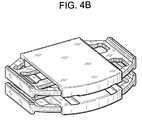
- FIG. 4 bis a perspective view of the pair of opposed endplates of FIG. 4 a , wherein the planks are in an expanded position.
- FIG. 4 cis a perspective view of the pair of opposed endplates of FIG. 4 b having intervertebral struts placed therebetween.
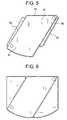
- FIG. 5discloses a parallelogram-type endplate having pivoting planks in a contracted state.
- FIG. 6discloses a parallelogram-type endplate having pivoting planks in an expanded state.
- FIG. 7discloses a fan-type endplate having pivoting planks in a contracted state.
- FIG. 8discloses a fan-type endplate having pivoting planks in an expanded state.
- an intervertebral prosthetic device having an expandable endplatecomprising:
- first and second cutoutsare joined by a third recessed surface 22 in the outer surface of the first base portion.
- the first plank of this embodimenthas a substantially T shape having a first shaft portion 23 having an first outer end portion 25 , a first inner end portion 27 and a first pair of flexible arms 29 extending from the outer end portion
- the first pair of flexible armsis received in the first cutout in a contracted position (not shown) in order to minimize the profile of the endplate.
- the contraction of the armsis caused by the flexible arms bearing against an inner rim 31 of the cutout.
- the plankis slid outwards from the cutout (as shown in FIG. 1 ), and the first pair of flexible arms becomes free of the bias of the inner rim of the cutout, and thereby expands.
- the second plank of this embodimentalso has a substantially T shape having a second shaft portion 33 having a second outer end portion 35 , a second inner end portion 37 and a second pair of flexible arms 39 extending from the outer end portion. It behaves substantially similarly to the first plank during insertion and expansion, sliding from a contracted position to an expanded position.
- the two planksare designed to interweave with one another in both the contracted and expanded positions.
- the endplateis designed so that the first outer end portion of the first plank is slidably received in a recess 41 in the second inner end portion of the second plank.
- the first outer end portion of the first plankis nearly fully received in a recess in the second inner end portion of the second plank.
- a first flange 43 extending from the first outer end portion of the first plankbears against a second flange 45 extending from the second outer end portion of the second plank, thereby preventing further outward movement of the planks so as to partially stabilize the expanded position construct.
- the end portions of the freed flexible armsmay now bear against the first side surface of the base portion so as to prevent retraction of the arms back into the cutouts and to stabilize the expanded position construct.
- the endplate of FIG. 1may further comprise:
- an intervertebral prosthetic devicehaving an expandable endplate, the endplate comprising:
- the inner surface of the endplatehas a functional feature thereon.
- the functional featureis an articulation surface 77 .
- the functional featurecan be an expandable bag that is attached to each of the inner surfaces of the opposed endplates and then filled with a compliant material after insertion.
- FIG. 3there is provided is a perspective view of an endplate of FIG. 2 , wherein the planks are in an expanded position. Extending from the outer end portion of the T shaped plank is handle 76 . After insertion, these handles are pulled outwardly to expand the endplate.
- FIG. 4 aif the implant is to be a fusion cage, then it is desirable to use two endplates 80 having sleeves to enclose planks, shown here in their contracted position.
- FIG. 4 bshows the endplates provided in an opposed relationship with their planks in an expanded position.
- FIG. 4 cis a perspective view of the pair of opposed endplates of FIG. 4 b having intervertebral struts 81 placed therebetween.
- the functional feature upon the inner surface 82 of the endplateis adapted to connect to a first load-bearing strut.
- the embodimentmay further include a second functional feature adapted to connect to a second load-bearing strut.
- the functional featureis a recessed groove 83 .
- endplateshaving throughholes extending between the inner and outer surfaces of the endplates so as to accommodate fusion. This may be accomplished by providing holes through the first and second base portions of each endplate. These througholes are adapted to provide bone growth therethrough in order to facilitate the fusion of the disc space.
- the strutsare provided with an angle, of typically between about 5 and about 15 degrees. These angled struts may be used to provide the endplate with a lordotic orientation.
- the endplateis made expandable by providing pivoting planks within a sleeve.
- an intervertebral prosthetic devicehaving an expandable endplate, the endplate comprising:
- the sleeveitself has a substantially parallelogram shape comprising a first acute corner 97 and a second opposite acute corner 99 .
- the first plankis pivotally connected to the sleeve in the first acute corner of the sleeve
- the second plankis pivotally connected to the sleeve in a second opposite acute corner of the sleeve.
- the endplatesare inserted into the disc space in a contracted position. Once the endplates are in the disc space, the planks are swung out of their respective recesses to their expanded positions.
- the expanded configurationforms a D-shaped footprint, thereby mimicking the footprint of the natural vertebral endplate.
- an intervertebral prosthetic devicehaving an expandable endplate, the endplate comprising:
- the pivot pinextends substantially through a midportion 113 of each plank.
- the endplateIn use, the endplate is inserted into the disc space in a contracted, aligned position. Once the endplate is in the disc space, the planks are rotated about the pivot pin from their respective aligned positions to take their expanded positions.
- the expanded configurationforms a D-shaped footprint, thereby mimicking the footprint of the natural vertebral endplate.
- plank surfacesare recessed to provide nesting with an adjacent plank. This nesting feature not only can allow the individual surfaces of the adjacent planks to combine into a single planar surface, it also locks the planks into their desired orientation.
- the outer surface of an endplate of the present inventioncan be either flat, curved or domed to match the natural vertebral endplate.
- the geometry of the inferior surfacecan be designed so that it will match the shape of the patient's vertebral endplate after the vertebral endplate has been modified by an endplate-shaping instrument.
- the outer surface of this endplatecan further comprise features to promote and secure initial fixation and bony ingrowth including, but not limited to, spikes, keels, teeth, projections (such as dovetails), recesses (such as grooves), throughholes and porous coatings.
Landscapes
- Health & Medical Sciences (AREA)
- Engineering & Computer Science (AREA)
- Biomedical Technology (AREA)
- Neurology (AREA)
- Orthopedic Medicine & Surgery (AREA)
- Cardiology (AREA)
- Oral & Maxillofacial Surgery (AREA)
- Transplantation (AREA)
- Heart & Thoracic Surgery (AREA)
- Vascular Medicine (AREA)
- Life Sciences & Earth Sciences (AREA)
- Animal Behavior & Ethology (AREA)
- General Health & Medical Sciences (AREA)
- Public Health (AREA)
- Veterinary Medicine (AREA)
- Prostheses (AREA)
Abstract
Description
- a) a first base portion having an outer surface adapted for bearing against a natural endplate, an inner surface, first and second side surfaces extending between the outer and inner surfaces, a first cutout opening onto the outer surface and the first side surface and forming a first recessed surface, and
- b) a first plank slidingly receivable within the first cutout and adapted to translate across the first recessed surface.
- a) a
first base portion 1 having anouter surface 3 adapted for bearing against a natural endplate, aninner surface 5, first7 and second9 side surfaces extending between the outer and inner surfaces, afirst cutout 11 opening onto the outer surface and the first side surface and forming a firstrecessed surface 13, and asecond cutout 15 opening onto the outer surface and the second side surface and forming a secondrecessed surface 17, - b) a
first plank 19 slidingly receivable within the first cutout and adapted to translate across the first recessed surface, and - c) a
second plank 21 slidingly receivable within the second cutout and adapted to translate across the second recessed surface.
- a) a
- c) a
second base portion 51 connected with the first base portion and having aninner surface 53 opposing theouter surface 3 of the first base portion to enclose the first plank within the first cutout and the second plank within the second cutout. The purpose of the second base portion is to prevent the planks from moving out of the cutouts, thereby partially stabilizing the expanded position construct.
- c) a
- a) a
sleeve 61 having anouter surface 63 adapted for bearing against a natural endplate, aninner surface 65, first67 andsecond side 69 surfaces extending between the outer and inner surfaces, afirst recess 71 extending into the sleeve from the first side surface, and a second recess extending into the sleeve from the first side surface, - b) a
first plank 73 slidably received in the first recess of the sleeve, and - c) a
second plank 75 slidably received in the second recess of the sleeve.
- a) a
- a) a
sleeve 91 having anouter surface 93 adapted for bearing against a natural endplate, an inner surface, first and second side surfaces extending between the outer and inner surfaces, a first recess extending into the sleeve from the first side surface, and a second recess extending into the sleeve from the first side surface, - b) a
first plank 94 slidably received in the first recess of the sleeve and pivotally connected to the sleeve, and - c) a
second plank 95 slidably received in the second recess of the sleeve and pivotally connected to the sleeve.
- a) a
- a) a first
outer plank 101 having anouter surface 103 adapted for bearing against a natural endplate, and an inner surface, and a first throughhole extending between the outer surface and the inner surface thereof, - b) a second
outer plank 105 having an outer surface adapted for bearing against a natural endplate, and aninner surface 107, and a second throughhole extending between the outer surface and the inner surface thereof, - c) an
inner plank 109 disposed between the inner surfaces of the outer planks and having a third throughhole extending therethrough, and - d) a
pivot pin 111 extending through each of the throughholes to pivotally connect the planks.
- a) a first
Claims (11)
Priority Applications (4)
| Application Number | Priority Date | Filing Date | Title |
|---|---|---|---|
| US11/694,524US8137401B2 (en) | 2007-03-30 | 2007-03-30 | Intervertebral device having expandable endplates |
| PCT/US2008/058563WO2008121759A2 (en) | 2007-03-30 | 2008-03-28 | Intervertebral device having expandable endplates |
| US13/281,833US8574297B2 (en) | 2007-03-30 | 2011-10-26 | Intervertebral device having expandable endplates |
| US14/028,934US8900305B2 (en) | 2007-03-30 | 2013-09-17 | Intervertebral device having expandable endplates |
Applications Claiming Priority (1)
| Application Number | Priority Date | Filing Date | Title |
|---|---|---|---|
| US11/694,524US8137401B2 (en) | 2007-03-30 | 2007-03-30 | Intervertebral device having expandable endplates |
Related Child Applications (1)
| Application Number | Title | Priority Date | Filing Date |
|---|---|---|---|
| US13/281,833ContinuationUS8574297B2 (en) | 2007-03-30 | 2011-10-26 | Intervertebral device having expandable endplates |
Publications (2)
| Publication Number | Publication Date |
|---|---|
| US20080243251A1 US20080243251A1 (en) | 2008-10-02 |
| US8137401B2true US8137401B2 (en) | 2012-03-20 |
Family
ID=39795710
Family Applications (3)
| Application Number | Title | Priority Date | Filing Date |
|---|---|---|---|
| US11/694,524Active2030-08-24US8137401B2 (en) | 2007-03-30 | 2007-03-30 | Intervertebral device having expandable endplates |
| US13/281,833ActiveUS8574297B2 (en) | 2007-03-30 | 2011-10-26 | Intervertebral device having expandable endplates |
| US14/028,934ActiveUS8900305B2 (en) | 2007-03-30 | 2013-09-17 | Intervertebral device having expandable endplates |
Family Applications After (2)
| Application Number | Title | Priority Date | Filing Date |
|---|---|---|---|
| US13/281,833ActiveUS8574297B2 (en) | 2007-03-30 | 2011-10-26 | Intervertebral device having expandable endplates |
| US14/028,934ActiveUS8900305B2 (en) | 2007-03-30 | 2013-09-17 | Intervertebral device having expandable endplates |
Country Status (2)
| Country | Link |
|---|---|
| US (3) | US8137401B2 (en) |
| WO (1) | WO2008121759A2 (en) |
Cited By (23)
| Publication number | Priority date | Publication date | Assignee | Title |
|---|---|---|---|---|
| US20110264154A1 (en)* | 2008-10-31 | 2011-10-27 | Zimmer, Inc. | Expandable arthroplasty plates |
| US20120059471A1 (en)* | 2004-09-23 | 2012-03-08 | Cervitech, Inc. | Prosthesis for partial replacement of a vertebral body |
| US20120296433A1 (en)* | 2010-02-02 | 2012-11-22 | Azadeh Farin | Spine surgery device |
| US8900305B2 (en) | 2007-03-30 | 2014-12-02 | DePuy Synthes Products, LLC | Intervertebral device having expandable endplates |
| US20150265422A1 (en)* | 2011-07-14 | 2015-09-24 | Nlt Spine Ltd. | Laterally Deflectable Implant |
| US9216096B2 (en) | 2010-03-16 | 2015-12-22 | Pinnacle Spine Group, Llc | Intervertebral implants and related tools |
| US9380932B1 (en) | 2011-11-02 | 2016-07-05 | Pinnacle Spine Group, Llc | Retractor devices for minimally invasive access to the spine |
| US9445918B1 (en) | 2012-10-22 | 2016-09-20 | Nuvasive, Inc. | Expandable spinal fusion implants and related instruments and methods |
| US9480574B2 (en) | 2013-03-14 | 2016-11-01 | Benvenue Medical, Inc. | Spinal fusion implants and devices and methods for deploying such implants |
| US9622876B1 (en) | 2012-04-25 | 2017-04-18 | Theken Spine, Llc | Expandable support device and method of use |
| US9642712B2 (en) | 2007-02-21 | 2017-05-09 | Benvenue Medical, Inc. | Methods for treating the spine |
| US9700425B1 (en) | 2011-03-20 | 2017-07-11 | Nuvasive, Inc. | Vertebral body replacement and insertion methods |
| US20170224506A1 (en)* | 2008-02-22 | 2017-08-10 | Howmedica Osteonics Corp. | Adjustable distraction cage with linked locking mechanisms |
| US10070970B2 (en) | 2013-03-14 | 2018-09-11 | Pinnacle Spine Group, Llc | Interbody implants and graft delivery systems |
| US10405988B2 (en) | 2008-02-22 | 2019-09-10 | Howmedica Osteonics Corp. | Spinal implant with expandable fixation |
| US10548738B2 (en) | 2016-04-07 | 2020-02-04 | Howmedica Osteonics Corp. | Expandable interbody implant |
| US11224453B2 (en) | 2014-07-08 | 2022-01-18 | Spinal Elements, Inc. | Apparatus and methods for disrupting intervertebral disc tissue |
| US11471145B2 (en) | 2018-03-16 | 2022-10-18 | Spinal Elements, Inc. | Articulated instrumentation and methods of using the same |
| US20230000642A1 (en)* | 2014-08-22 | 2023-01-05 | Globus Medical, Inc. | Vertebral implants and related methods of use |
| US11564811B2 (en) | 2015-02-06 | 2023-01-31 | Spinal Elements, Inc. | Graft material injector system and method |
| US11583327B2 (en) | 2018-01-29 | 2023-02-21 | Spinal Elements, Inc. | Minimally invasive interbody fusion |
| US11771483B2 (en) | 2017-03-22 | 2023-10-03 | Spinal Elements, Inc. | Minimal impact access system to disc space |
| US12232975B2 (en) | 2008-02-22 | 2025-02-25 | Howmedica Osteonics Corp. | Lockable spinal implant |
Families Citing this family (66)
| Publication number | Priority date | Publication date | Assignee | Title |
|---|---|---|---|---|
| US6793678B2 (en) | 2002-06-27 | 2004-09-21 | Depuy Acromed, Inc. | Prosthetic intervertebral motion disc having dampening |
| AU2004212942A1 (en) | 2003-02-14 | 2004-09-02 | Depuy Spine, Inc. | In-situ formed intervertebral fusion device |
| US20040267367A1 (en) | 2003-06-30 | 2004-12-30 | Depuy Acromed, Inc | Intervertebral implant with conformable endplate |
| US8636802B2 (en) | 2004-03-06 | 2014-01-28 | DePuy Synthes Products, LLC | Dynamized interspinal implant |
| US8366773B2 (en) | 2005-08-16 | 2013-02-05 | Benvenue Medical, Inc. | Apparatus and method for treating bone |
| WO2008103781A2 (en) | 2007-02-21 | 2008-08-28 | Benvenue Medical, Inc. | Devices for treating the spine |
| AU2006279558B2 (en) | 2005-08-16 | 2012-05-17 | Izi Medical Products, Llc | Spinal tissue distraction devices |
| WO2008070863A2 (en) | 2006-12-07 | 2008-06-12 | Interventional Spine, Inc. | Intervertebral implant |
| US8900307B2 (en) | 2007-06-26 | 2014-12-02 | DePuy Synthes Products, LLC | Highly lordosed fusion cage |
| EP2237748B1 (en) | 2008-01-17 | 2012-09-05 | Synthes GmbH | An expandable intervertebral implant |
| US8936641B2 (en) | 2008-04-05 | 2015-01-20 | DePuy Synthes Products, LLC | Expandable intervertebral implant |
| WO2016044824A1 (en)* | 2008-05-07 | 2016-03-24 | George Frey | Configurable intervertebral implant |
| BRPI0921108A2 (en)* | 2008-12-22 | 2016-02-16 | Synthes Gmbh | expandable vertebral body replacement method and system |
| US9526620B2 (en) | 2009-03-30 | 2016-12-27 | DePuy Synthes Products, Inc. | Zero profile spinal fusion cage |
| KR101687435B1 (en) | 2009-07-06 | 2016-12-19 | 신세스 게엠바하 | Expandable fixation assemblies |
| US9393129B2 (en) | 2009-12-10 | 2016-07-19 | DePuy Synthes Products, Inc. | Bellows-like expandable interbody fusion cage |
| US9907560B2 (en) | 2010-06-24 | 2018-03-06 | DePuy Synthes Products, Inc. | Flexible vertebral body shavers |
| US8979860B2 (en) | 2010-06-24 | 2015-03-17 | DePuy Synthes Products. LLC | Enhanced cage insertion device |
| US8623091B2 (en) | 2010-06-29 | 2014-01-07 | DePuy Synthes Products, LLC | Distractible intervertebral implant |
| US20120078372A1 (en) | 2010-09-23 | 2012-03-29 | Thomas Gamache | Novel implant inserter having a laterally-extending dovetail engagement feature |
| US9402732B2 (en) | 2010-10-11 | 2016-08-02 | DePuy Synthes Products, Inc. | Expandable interspinous process spacer implant |
| US9308099B2 (en) | 2011-02-14 | 2016-04-12 | Imds Llc | Expandable intervertebral implants and instruments |
| US8486149B2 (en) | 2011-02-23 | 2013-07-16 | DePuy Synthes Products, LLC | Expandable interbody fusion implant |
| US9248028B2 (en) | 2011-09-16 | 2016-02-02 | DePuy Synthes Products, Inc. | Removable, bone-securing cover plate for intervertebral fusion cage |
| US9913732B2 (en)* | 2011-11-02 | 2018-03-13 | Spinesmith Partners, L.P. | Interbody fusion device with separable retention component for lateral approach and associated methods |
| EP2877127B1 (en) | 2012-07-26 | 2019-08-21 | Synthes GmbH | Expandable implant |
| US9717601B2 (en) | 2013-02-28 | 2017-08-01 | DePuy Synthes Products, Inc. | Expandable intervertebral implant, system, kit and method |
| US9198772B2 (en) | 2013-03-01 | 2015-12-01 | Globus Medical, Inc. | Articulating expandable intervertebral implant |
| US10004607B2 (en) | 2013-03-01 | 2018-06-26 | Globus Medical, Inc. | Articulating expandable intervertebral implant |
| US9770343B2 (en) | 2013-03-01 | 2017-09-26 | Globus Medical Inc. | Articulating expandable intervertebral implant |
| US9204972B2 (en) | 2013-03-01 | 2015-12-08 | Globus Medical, Inc. | Articulating expandable intervertebral implant |
| US9522070B2 (en) | 2013-03-07 | 2016-12-20 | Interventional Spine, Inc. | Intervertebral implant |
| US12193948B2 (en) | 2013-03-13 | 2025-01-14 | Life Spine, Inc. | Expandable implant assembly |
| US10426632B2 (en) | 2013-03-13 | 2019-10-01 | Life Spine, Inc. | Expandable spinal interbody assembly |
| US10085783B2 (en) | 2013-03-14 | 2018-10-02 | Izi Medical Products, Llc | Devices and methods for treating bone tissue |
| EP2777632B1 (en)* | 2013-03-15 | 2020-04-22 | Howmedica Osteonics Corp. | Adjustable distraction cage with linked locking mechanisms. |
| US9795493B1 (en) | 2013-03-15 | 2017-10-24 | Nuvasive, Inc. | Expandable intervertebral implant and methods of use thereof |
| US11426290B2 (en) | 2015-03-06 | 2022-08-30 | DePuy Synthes Products, Inc. | Expandable intervertebral implant, system, kit and method |
| US9913727B2 (en) | 2015-07-02 | 2018-03-13 | Medos International Sarl | Expandable implant |
| JP6949006B2 (en) | 2015-08-25 | 2021-10-13 | アイエムディーエス リミテッド ライアビリティ カンパニー | Expandable facet implant |
| WO2017066226A1 (en)* | 2015-10-16 | 2017-04-20 | Globus Medical, Inc. | Articulating expandable intervertebral implant |
| US11039934B2 (en) | 2016-06-10 | 2021-06-22 | Bryan Barnes Pc. | Expandable spinal fusion device and method |
| US11510788B2 (en) | 2016-06-28 | 2022-11-29 | Eit Emerging Implant Technologies Gmbh | Expandable, angularly adjustable intervertebral cages |
| EP3474784A2 (en) | 2016-06-28 | 2019-05-01 | Eit Emerging Implant Technologies GmbH | Expandable and angularly adjustable intervertebral cages with articulating joint |
| WO2018081322A1 (en) | 2016-10-25 | 2018-05-03 | Imds Llc | Methods and instrumentation for intervertebral cage expansion |
| US10537436B2 (en) | 2016-11-01 | 2020-01-21 | DePuy Synthes Products, Inc. | Curved expandable cage |
| US10888433B2 (en) | 2016-12-14 | 2021-01-12 | DePuy Synthes Products, Inc. | Intervertebral implant inserter and related methods |
| US10398563B2 (en) | 2017-05-08 | 2019-09-03 | Medos International Sarl | Expandable cage |
| US11344424B2 (en) | 2017-06-14 | 2022-05-31 | Medos International Sarl | Expandable intervertebral implant and related methods |
| US10940016B2 (en) | 2017-07-05 | 2021-03-09 | Medos International Sarl | Expandable intervertebral fusion cage |
| US11896494B2 (en) | 2017-07-10 | 2024-02-13 | Life Spine, Inc. | Expandable implant assembly |
| US10945859B2 (en) | 2018-01-29 | 2021-03-16 | Amplify Surgical, Inc. | Expanding fusion cages |
| US11446156B2 (en) | 2018-10-25 | 2022-09-20 | Medos International Sarl | Expandable intervertebral implant, inserter instrument, and related methods |
| US11382764B2 (en) | 2019-06-10 | 2022-07-12 | Life Spine, Inc. | Expandable implant assembly with compression features |
| US12042395B2 (en) | 2019-06-11 | 2024-07-23 | Life Spine, Inc. | Expandable implant assembly |
| US11426286B2 (en) | 2020-03-06 | 2022-08-30 | Eit Emerging Implant Technologies Gmbh | Expandable intervertebral implant |
| US11857432B2 (en) | 2020-04-13 | 2024-01-02 | Life Spine, Inc. | Expandable implant assembly |
| US11602439B2 (en) | 2020-04-16 | 2023-03-14 | Life Spine, Inc. | Expandable implant assembly |
| US12336917B2 (en) | 2020-05-15 | 2025-06-24 | Life Spine, Inc. | Steerable implant assembly |
| US11602440B2 (en) | 2020-06-25 | 2023-03-14 | Life Spine, Inc. | Expandable implant assembly |
| US11554020B2 (en) | 2020-09-08 | 2023-01-17 | Life Spine, Inc. | Expandable implant with pivoting control assembly |
| US11850160B2 (en) | 2021-03-26 | 2023-12-26 | Medos International Sarl | Expandable lordotic intervertebral fusion cage |
| US11752009B2 (en) | 2021-04-06 | 2023-09-12 | Medos International Sarl | Expandable intervertebral fusion cage |
| US11896491B2 (en)* | 2021-10-19 | 2024-02-13 | Loubert S. Suddaby | Expandable total disc replacement implant |
| US11583410B1 (en)* | 2021-10-19 | 2023-02-21 | Loubert S. Suddaby | Expandable total disc replacement implant |
| US12090064B2 (en) | 2022-03-01 | 2024-09-17 | Medos International Sarl | Stabilization members for expandable intervertebral implants, and related systems and methods |
Citations (14)
| Publication number | Priority date | Publication date | Assignee | Title |
|---|---|---|---|---|
| US5928284A (en) | 1998-07-09 | 1999-07-27 | Mehdizadeh; Hamid M. | Disc replacement prosthesis |
| US6102950A (en) | 1999-01-19 | 2000-08-15 | Vaccaro; Alex | Intervertebral body fusion device |
| US20040030387A1 (en)* | 2002-03-11 | 2004-02-12 | Landry Michael E. | Instrumentation and procedure for implanting spinal implant devices |
| US20040087947A1 (en) | 2002-08-28 | 2004-05-06 | Roy Lim | Minimally invasive expanding spacer and method |
| US20040088054A1 (en)* | 2002-11-01 | 2004-05-06 | Bret Berry | Laterally expandable cage |
| US20050060037A1 (en) | 2000-07-07 | 2005-03-17 | Michelson Gary Karlin | Expandable implant with interlocking walls and method for use thereof |
| US20050071007A1 (en) | 2003-09-30 | 2005-03-31 | Malek Michel H. | Intervertebral disc prosthesis |
| US20050197702A1 (en) | 2002-08-15 | 2005-09-08 | Coppes Justin K. | Intervertebral disc implant |
| US20050209698A1 (en) | 2003-08-05 | 2005-09-22 | Gordon Charles R | Expandable intervertebral implant |
| US20050256576A1 (en) | 2004-05-13 | 2005-11-17 | Moskowitz Nathan C | Artificial expansile total lumbar and thoracic discs for posterior placement without supplemental instrumentation and its adaptation for anterior placement of artificial cervical, thoracic and lumbar discs |
| WO2006058281A2 (en) | 2004-11-23 | 2006-06-01 | Glenn Bradley J | Minimally invasive spinal disc stabilizer and insertion tool |
| US7101375B2 (en) | 1997-01-02 | 2006-09-05 | St. Francis Medical Technologies, Inc. | Spine distraction implant |
| US20060224241A1 (en) | 2005-03-31 | 2006-10-05 | Life Spine, Llc | Expandable spinal interbody and intravertebral body devices |
| US20070055378A1 (en) | 2003-07-31 | 2007-03-08 | Ankney David W | Transforaminal prosthetic spinal disc replacement and methods thereof |
Family Cites Families (1)
| Publication number | Priority date | Publication date | Assignee | Title |
|---|---|---|---|---|
| US8137401B2 (en) | 2007-03-30 | 2012-03-20 | Depuy Spine, Inc. | Intervertebral device having expandable endplates |
- 2007
- 2007-03-30USUS11/694,524patent/US8137401B2/enactiveActive
- 2008
- 2008-03-28WOPCT/US2008/058563patent/WO2008121759A2/enactiveApplication Filing
- 2011
- 2011-10-26USUS13/281,833patent/US8574297B2/enactiveActive
- 2013
- 2013-09-17USUS14/028,934patent/US8900305B2/enactiveActive
Patent Citations (14)
| Publication number | Priority date | Publication date | Assignee | Title |
|---|---|---|---|---|
| US7101375B2 (en) | 1997-01-02 | 2006-09-05 | St. Francis Medical Technologies, Inc. | Spine distraction implant |
| US5928284A (en) | 1998-07-09 | 1999-07-27 | Mehdizadeh; Hamid M. | Disc replacement prosthesis |
| US6102950A (en) | 1999-01-19 | 2000-08-15 | Vaccaro; Alex | Intervertebral body fusion device |
| US20050060037A1 (en) | 2000-07-07 | 2005-03-17 | Michelson Gary Karlin | Expandable implant with interlocking walls and method for use thereof |
| US20040030387A1 (en)* | 2002-03-11 | 2004-02-12 | Landry Michael E. | Instrumentation and procedure for implanting spinal implant devices |
| US20050197702A1 (en) | 2002-08-15 | 2005-09-08 | Coppes Justin K. | Intervertebral disc implant |
| US20040087947A1 (en) | 2002-08-28 | 2004-05-06 | Roy Lim | Minimally invasive expanding spacer and method |
| US20040088054A1 (en)* | 2002-11-01 | 2004-05-06 | Bret Berry | Laterally expandable cage |
| US20070055378A1 (en) | 2003-07-31 | 2007-03-08 | Ankney David W | Transforaminal prosthetic spinal disc replacement and methods thereof |
| US20050209698A1 (en) | 2003-08-05 | 2005-09-22 | Gordon Charles R | Expandable intervertebral implant |
| US20050071007A1 (en) | 2003-09-30 | 2005-03-31 | Malek Michel H. | Intervertebral disc prosthesis |
| US20050256576A1 (en) | 2004-05-13 | 2005-11-17 | Moskowitz Nathan C | Artificial expansile total lumbar and thoracic discs for posterior placement without supplemental instrumentation and its adaptation for anterior placement of artificial cervical, thoracic and lumbar discs |
| WO2006058281A2 (en) | 2004-11-23 | 2006-06-01 | Glenn Bradley J | Minimally invasive spinal disc stabilizer and insertion tool |
| US20060224241A1 (en) | 2005-03-31 | 2006-10-05 | Life Spine, Llc | Expandable spinal interbody and intravertebral body devices |
Cited By (54)
| Publication number | Priority date | Publication date | Assignee | Title |
|---|---|---|---|---|
| US20120059471A1 (en)* | 2004-09-23 | 2012-03-08 | Cervitech, Inc. | Prosthesis for partial replacement of a vertebral body |
| US8409285B2 (en)* | 2004-09-23 | 2013-04-02 | Cervitech, Inc. | Prosthesis for partial replacement of a vertebral body |
| US10575963B2 (en) | 2007-02-21 | 2020-03-03 | Benvenue Medical, Inc. | Devices for treating the spine |
| US10285821B2 (en) | 2007-02-21 | 2019-05-14 | Benvenue Medical, Inc. | Devices for treating the spine |
| US10426629B2 (en) | 2007-02-21 | 2019-10-01 | Benvenue Medical, Inc. | Devices for treating the spine |
| US9642712B2 (en) | 2007-02-21 | 2017-05-09 | Benvenue Medical, Inc. | Methods for treating the spine |
| US8900305B2 (en) | 2007-03-30 | 2014-12-02 | DePuy Synthes Products, LLC | Intervertebral device having expandable endplates |
| US11202712B2 (en) | 2008-02-22 | 2021-12-21 | Howmedica Osteonics Corp. | Spinal implant with expandable fixation |
| US20170224506A1 (en)* | 2008-02-22 | 2017-08-10 | Howmedica Osteonics Corp. | Adjustable distraction cage with linked locking mechanisms |
| US10342673B2 (en)* | 2008-02-22 | 2019-07-09 | Howmedica Osteonics Corp. | Adjustable distraction cage with linked locking mechanisms |
| US10405988B2 (en) | 2008-02-22 | 2019-09-10 | Howmedica Osteonics Corp. | Spinal implant with expandable fixation |
| US11191647B2 (en) | 2008-02-22 | 2021-12-07 | Howmedica Osteonics Corp. | Adjustable distraction cage with linked locking mechanisms |
| US12232975B2 (en) | 2008-02-22 | 2025-02-25 | Howmedica Osteonics Corp. | Lockable spinal implant |
| US20110264154A1 (en)* | 2008-10-31 | 2011-10-27 | Zimmer, Inc. | Expandable arthroplasty plates |
| US8845641B2 (en)* | 2008-10-31 | 2014-09-30 | Zimmer, Inc. | Expandable arthroplasty plates |
| US9545319B2 (en) | 2010-02-02 | 2017-01-17 | Azadeh Farin Wald, M.D., Inc., A Medical Corporation | Spine surgery device |
| US9078769B2 (en)* | 2010-02-02 | 2015-07-14 | Azadeh Farin | Spine surgery device |
| US20120296433A1 (en)* | 2010-02-02 | 2012-11-22 | Azadeh Farin | Spine surgery device |
| US11701235B2 (en) | 2010-02-02 | 2023-07-18 | Azadeh Farin Wald, M.D., Inc., A Medical Corporation | Spine surgery device |
| US9649203B2 (en) | 2010-03-16 | 2017-05-16 | Pinnacle Spine Group, Llc | Methods of post-filling an intervertebral implant |
| US9216096B2 (en) | 2010-03-16 | 2015-12-22 | Pinnacle Spine Group, Llc | Intervertebral implants and related tools |
| US9788973B2 (en) | 2010-03-16 | 2017-10-17 | Pinnacle Spine Group, Llc | Spinal implant |
| US10485672B2 (en) | 2011-03-20 | 2019-11-26 | Nuvasive, Inc. | Vertebral body replacement and insertion methods |
| US12186198B2 (en) | 2011-03-20 | 2025-01-07 | Nuvasive, Inc. | Vertebral body replacement and insertion methods |
| US11389301B2 (en) | 2011-03-20 | 2022-07-19 | Nuvasive, Inc. | Vertebral body replacement and insertion methods |
| US9700425B1 (en) | 2011-03-20 | 2017-07-11 | Nuvasive, Inc. | Vertebral body replacement and insertion methods |
| US20150265422A1 (en)* | 2011-07-14 | 2015-09-24 | Nlt Spine Ltd. | Laterally Deflectable Implant |
| US10617530B2 (en) | 2011-07-14 | 2020-04-14 | Seaspine, Inc. | Laterally deflectable implant |
| US12029655B2 (en) | 2011-07-14 | 2024-07-09 | Seaspine, Inc. | Laterally deflectable implant |
| US9380932B1 (en) | 2011-11-02 | 2016-07-05 | Pinnacle Spine Group, Llc | Retractor devices for minimally invasive access to the spine |
| US9622876B1 (en) | 2012-04-25 | 2017-04-18 | Theken Spine, Llc | Expandable support device and method of use |
| US10702392B2 (en) | 2012-04-25 | 2020-07-07 | Theken Spine, Llc | Expandable support device and method of use |
| US12419759B2 (en) | 2012-04-25 | 2025-09-23 | Seaspine Orthopedics Corporation | Expandable support device and method of use |
| US11534312B2 (en) | 2012-04-25 | 2022-12-27 | Theken Spine, Llc | Expandable support device and method of use |
| US10350084B1 (en) | 2012-10-22 | 2019-07-16 | Nuvasive, Inc. | Expandable spinal fusion implant, related instruments and methods |
| US9445918B1 (en) | 2012-10-22 | 2016-09-20 | Nuvasive, Inc. | Expandable spinal fusion implants and related instruments and methods |
| US11399954B2 (en) | 2012-10-22 | 2022-08-02 | Nuvasive, Inc. | Expandable spinal fusion implant, related instruments and methods |
| US12048635B2 (en) | 2012-10-22 | 2024-07-30 | Nuvasive, Inc. | Expandable spinal fusion implant, related instruments and methods |
| US9480574B2 (en) | 2013-03-14 | 2016-11-01 | Benvenue Medical, Inc. | Spinal fusion implants and devices and methods for deploying such implants |
| US10070970B2 (en) | 2013-03-14 | 2018-09-11 | Pinnacle Spine Group, Llc | Interbody implants and graft delivery systems |
| USRE49994E1 (en) | 2013-03-14 | 2024-06-04 | Spinal Elements, Inc. | Spinal fusion implants and devices and methods for deploying such implants |
| US11224453B2 (en) | 2014-07-08 | 2022-01-18 | Spinal Elements, Inc. | Apparatus and methods for disrupting intervertebral disc tissue |
| US12053196B2 (en) | 2014-07-08 | 2024-08-06 | Spinal Elements, Inc. | Apparatus and methods for disrupting inter vertebral disc tissue |
| US20230000642A1 (en)* | 2014-08-22 | 2023-01-05 | Globus Medical, Inc. | Vertebral implants and related methods of use |
| US12083024B2 (en)* | 2014-08-22 | 2024-09-10 | Globus Medical, Inc. | Vertebral implants and related methods of use |
| US11564811B2 (en) | 2015-02-06 | 2023-01-31 | Spinal Elements, Inc. | Graft material injector system and method |
| US12121456B2 (en) | 2015-02-06 | 2024-10-22 | Spinal Elements, Inc. | Graft material injector system and method |
| US11583407B2 (en) | 2016-04-07 | 2023-02-21 | Howmedica Osteonics Corp. | Expandable interbody implant |
| US10548738B2 (en) | 2016-04-07 | 2020-02-04 | Howmedica Osteonics Corp. | Expandable interbody implant |
| US11771483B2 (en) | 2017-03-22 | 2023-10-03 | Spinal Elements, Inc. | Minimal impact access system to disc space |
| US12207856B2 (en) | 2018-01-29 | 2025-01-28 | Spinal Elements, Inc. | Minimally invasive interbody fusion |
| US11583327B2 (en) | 2018-01-29 | 2023-02-21 | Spinal Elements, Inc. | Minimally invasive interbody fusion |
| US11471145B2 (en) | 2018-03-16 | 2022-10-18 | Spinal Elements, Inc. | Articulated instrumentation and methods of using the same |
| US12357291B2 (en) | 2018-03-16 | 2025-07-15 | Spinal Elements, Inc. | Articulated instrumentation and methods of using the same |
Also Published As
| Publication number | Publication date |
|---|---|
| US8574297B2 (en) | 2013-11-05 |
| US8900305B2 (en) | 2014-12-02 |
| US20080243251A1 (en) | 2008-10-02 |
| US20140018921A1 (en) | 2014-01-16 |
| US20120041561A1 (en) | 2012-02-16 |
| WO2008121759A3 (en) | 2009-09-24 |
| WO2008121759A2 (en) | 2008-10-09 |
Similar Documents
| Publication | Publication Date | Title |
|---|---|---|
| US8137401B2 (en) | Intervertebral device having expandable endplates | |
| US20230181332A1 (en) | Expandable and angularly adjustable intervertebral cages with articulating joint | |
| US12390343B2 (en) | Expandable, angularly adjustable intervertebral cages | |
| US6193757B1 (en) | Expandable intervertebral spacers | |
| US7887589B2 (en) | Minimally invasive spinal disc stabilizer and insertion tool | |
| US20080208345A1 (en) | Intervertebral implant | |
| US20060036325A1 (en) | Anterior prosthetic spinal disc replacement | |
| WO2009129605A1 (en) | Artificial intervertebral spacer | |
| CN100560038C (en) | Controlled artificial intervertebral disc implant | |
| US12042397B2 (en) | Intervertebral implant | |
| US12102537B2 (en) | Minimally invasive expandable intervertebral fusion implant |
Legal Events
| Date | Code | Title | Description |
|---|---|---|---|
| AS | Assignment | Owner name:DEPUY SPINE, INC., MASSACHUSETTS Free format text:ASSIGNMENT OF ASSIGNORS INTEREST;ASSIGNORS:STAD, SHAWN;RAMSAY, CHRISTOPHER;REEL/FRAME:019409/0298;SIGNING DATES FROM 20070523 TO 20070524 Owner name:DEPUY SPINE, INC., MASSACHUSETTS Free format text:ASSIGNMENT OF ASSIGNORS INTEREST;ASSIGNORS:STAD, SHAWN;RAMSAY, CHRISTOPHER;SIGNING DATES FROM 20070523 TO 20070524;REEL/FRAME:019409/0298 | |
| STCF | Information on status: patent grant | Free format text:PATENTED CASE | |
| AS | Assignment | Owner name:HAND INNOVATIONS LLC, FLORIDA Free format text:ASSIGNMENT OF ASSIGNORS INTEREST;ASSIGNOR:DEPUY SPINE, LLC;REEL/FRAME:030511/0501 Effective date:20121230 Owner name:DEPUY SYNTHES PRODUCTS, LLC, MASSACHUSETTS Free format text:CHANGE OF NAME;ASSIGNOR:HAND INNOVATIONS LLC;REEL/FRAME:030512/0014 Effective date:20121231 Owner name:DEPUY SPINE, LLC, MASSACHUSETTS Free format text:CHANGE OF NAME;ASSIGNOR:DEPUY SPINE, INC.;REEL/FRAME:030511/0551 Effective date:20121230 | |
| FPAY | Fee payment | Year of fee payment:4 | |
| MAFP | Maintenance fee payment | Free format text:PAYMENT OF MAINTENANCE FEE, 8TH YEAR, LARGE ENTITY (ORIGINAL EVENT CODE: M1552); ENTITY STATUS OF PATENT OWNER: LARGE ENTITY Year of fee payment:8 | |
| MAFP | Maintenance fee payment | Free format text:PAYMENT OF MAINTENANCE FEE, 12TH YEAR, LARGE ENTITY (ORIGINAL EVENT CODE: M1553); ENTITY STATUS OF PATENT OWNER: LARGE ENTITY Year of fee payment:12 |