US8137387B2 - Pedicle screw assembly with inclined surface seat - Google Patents
Pedicle screw assembly with inclined surface seatDownload PDFInfo
- Publication number
- US8137387B2 US8137387B2US11/777,945US77794507AUS8137387B2US 8137387 B2US8137387 B2US 8137387B2US 77794507 AUS77794507 AUS 77794507AUS 8137387 B2US8137387 B2US 8137387B2
- Authority
- US
- United States
- Prior art keywords
- coupling element
- saddle
- projections
- compression nut
- head portion
- Prior art date
- Legal status (The legal status is an assumption and is not a legal conclusion. Google has not performed a legal analysis and makes no representation as to the accuracy of the status listed.)
- Expired - Fee Related, expires
Links
- 230000008878couplingEffects0.000claimsabstractdescription271
- 238000010168coupling processMethods0.000claimsabstractdescription271
- 238000005859coupling reactionMethods0.000claimsabstractdescription271
- 230000006835compressionEffects0.000claimsabstractdescription138
- 238000007906compressionMethods0.000claimsabstractdescription138
- 210000000988bone and boneAnatomy0.000claimsabstractdescription52
- 239000003381stabilizerSubstances0.000claimsabstractdescription38
- 238000007373indentationMethods0.000claimsdescription16
- 230000014759maintenance of locationEffects0.000description29
- 230000000284resting effectEffects0.000description10
- 230000004044responseEffects0.000description8
- 238000003780insertionMethods0.000description6
- 230000037431insertionEffects0.000description6
- 238000000034methodMethods0.000description5
- 239000011295pitchSubstances0.000description5
- 230000007480spreadingEffects0.000description5
- 230000006641stabilisationEffects0.000description5
- 238000011105stabilizationMethods0.000description5
- 238000002513implantationMethods0.000description4
- 230000000295complement effectEffects0.000description3
- 230000013011matingEffects0.000description3
- 238000001356surgical procedureMethods0.000description3
- 229910001069Ti alloyInorganic materials0.000description2
- RTAQQCXQSZGOHL-UHFFFAOYSA-NTitaniumChemical compound[Ti]RTAQQCXQSZGOHL-UHFFFAOYSA-N0.000description2
- 230000000712assemblyEffects0.000description2
- 238000000429assemblyMethods0.000description2
- 230000015572biosynthetic processEffects0.000description2
- 230000004927fusionEffects0.000description2
- 230000007246mechanismEffects0.000description2
- 239000010936titaniumSubstances0.000description2
- 229910052719titaniumInorganic materials0.000description2
- 0CCCC(C*(C1)=C)C1C(C)CChemical compoundCCCC(C*(C1)=C)C1C(C)C0.000description1
- 206010058907Spinal deformityDiseases0.000description1
- 208000020339Spinal injuryDiseases0.000description1
- 230000007797corrosionEffects0.000description1
- 238000005260corrosionMethods0.000description1
- 230000007423decreaseEffects0.000description1
- 230000007547defectEffects0.000description1
- 238000006073displacement reactionMethods0.000description1
- 238000002594fluoroscopyMethods0.000description1
- -1for exampleSubstances0.000description1
- 230000008570general processEffects0.000description1
- 239000007943implantSubstances0.000description1
- 208000014674injuryDiseases0.000description1
- 239000000463materialSubstances0.000description1
- 229910052751metalInorganic materials0.000description1
- 239000002184metalSubstances0.000description1
- 210000005036nerveAnatomy0.000description1
- 230000000399orthopedic effectEffects0.000description1
- 230000008569processEffects0.000description1
- 238000011084recoveryMethods0.000description1
- 230000000717retained effectEffects0.000description1
- 239000007787solidSubstances0.000description1
- 230000000087stabilizing effectEffects0.000description1
- 239000010935stainless steelSubstances0.000description1
- 229910001220stainless steelInorganic materials0.000description1
- 210000000115thoracic cavityAnatomy0.000description1
- 230000008733traumaEffects0.000description1
- 238000012800visualizationMethods0.000description1
Images


Classifications
- A—HUMAN NECESSITIES
- A61—MEDICAL OR VETERINARY SCIENCE; HYGIENE
- A61B—DIAGNOSIS; SURGERY; IDENTIFICATION
- A61B17/00—Surgical instruments, devices or methods
- A61B17/56—Surgical instruments or methods for treatment of bones or joints; Devices specially adapted therefor
- A61B17/58—Surgical instruments or methods for treatment of bones or joints; Devices specially adapted therefor for osteosynthesis, e.g. bone plates, screws or setting implements
- A61B17/68—Internal fixation devices, including fasteners and spinal fixators, even if a part thereof projects from the skin
- A61B17/70—Spinal positioners or stabilisers, e.g. stabilisers comprising fluid filler in an implant
- A61B17/7001—Screws or hooks combined with longitudinal elements which do not contact vertebrae
- A61B17/7035—Screws or hooks, wherein a rod-clamping part and a bone-anchoring part can pivot relative to each other
- A61B17/7037—Screws or hooks, wherein a rod-clamping part and a bone-anchoring part can pivot relative to each other wherein pivoting is blocked when the rod is clamped
- A—HUMAN NECESSITIES
- A61—MEDICAL OR VETERINARY SCIENCE; HYGIENE
- A61B—DIAGNOSIS; SURGERY; IDENTIFICATION
- A61B17/00—Surgical instruments, devices or methods
- A61B17/56—Surgical instruments or methods for treatment of bones or joints; Devices specially adapted therefor
- A61B17/58—Surgical instruments or methods for treatment of bones or joints; Devices specially adapted therefor for osteosynthesis, e.g. bone plates, screws or setting implements
- A61B17/68—Internal fixation devices, including fasteners and spinal fixators, even if a part thereof projects from the skin
- A61B17/70—Spinal positioners or stabilisers, e.g. stabilisers comprising fluid filler in an implant
- A61B17/7001—Screws or hooks combined with longitudinal elements which do not contact vertebrae
- A61B17/7032—Screws or hooks with U-shaped head or back through which longitudinal rods pass
- A—HUMAN NECESSITIES
- A61—MEDICAL OR VETERINARY SCIENCE; HYGIENE
- A61B—DIAGNOSIS; SURGERY; IDENTIFICATION
- A61B90/00—Instruments, implements or accessories specially adapted for surgery or diagnosis and not covered by any of the groups A61B1/00 - A61B50/00, e.g. for luxation treatment or for protecting wound edges
- A61B90/03—Automatic limiting or abutting means, e.g. for safety
- A61B2090/037—Automatic limiting or abutting means, e.g. for safety with a frangible part, e.g. by reduced diameter
Definitions
- This disclosureis directed at skeletal bone fixation systems, and more particularly to a fixation assembly for vertebrae of a spinal column.
- a typical spinal fixation assemblyincludes a fixation device, such as a screw or hook, that can be attached to a portion of a first vertebral body.
- the screwcan be coupled to a stabilization member, such as an elongate rod, that can be linked to one or more additional vertebral bodies using additional screws.
- two or more bone screws and/or hooksare secured to a vertebral body that is to be stabilized. After the screws are secured to the vertebral bodies, the screws are coupled to a spinal stabilization rod that restricts movement of the stabilized vertebra. It is important that the screws have a secure coupling with the spinal stabilization rod in order to prevent movement of the rod relative to the screw after placement.
- a tulip-like coupling element with opposing upright arms or wallsis used to secure the pedicle screw to the rod.
- the coupling element and pedicle screware configured to be coupled to an elongate stabilizer, such as a rod, that is positioned above the head of the pedicle screw.
- a compression membersuch as a compression nut, is configured to mate with the coupling element and provides a compressive force to the rod. The rod is then forced against the head of the pedicle screw, and that force is translated to the coupling element. Accordingly, the forces generated by the compression nut clamp the rod and pedicle screw head together within the coupling element.
- Pedicle screw implantation proceduresare costly, risky and result in painful and lengthy recovery for the patient. Thus, it is important that multiple surgeries to resolve failures in the implants be avoided. Furthermore, it can be a tedious process to position the screws on the vertebral bodies and to interconnect them with the stabilizing rod. Thus, it is desirable that the screws be easily attached to the rods and that, once attached, the coupling between the screw and rod be secure and not prone to failure. In view of the foregoing, there is a need for improved pedicle screw systems.
- a bone stabilizer assemblyincludes a fixation element, a coupling element, a saddle, a compression nut, and retention means for retaining the saddle in the coupling element in a floating configuration that permits a predetermined amount of movement between the saddle and the coupling element.
- the fixation elementis adapted to engage a bone and has a head portion and shank portion.
- the coupling elementhas an internal bore sized to receive the shank portion of the fixation element and a seat adapted to support the head portion of the fixation element.
- the coupling elementis also adapted to receive a stabilizer rod.
- the saddleis movably mounted in the coupling element below the stabilizer rod when the stabilizer rod is in the coupling element.
- the compression nutis engagable with the coupling element.
- the compression nutis adapted to rotatingly move distally into the coupling element to translate a force to the head portion through the rod and the saddle such that the head portion is forced against the seat of the coupling element to prevent relative movement between the fixation element and the coupling element.
- a bone stabilizer assemblyin another aspect, includes a fixation element, a coupling element, and a saddle.
- the fixation elementis adapted to engage a bone and has a head portion and shank portion.
- the coupling elementhas an internal bore sized to receive the shank portion of the fixation element and a seat adapted to support the head portion of the fixation element.
- the coupling elementfurther includes a pair of opposed walls separated by a stabilizer rod-receiving channel. Inner surfaces of the opposed walls include inner threads for mating with a compression nut and opposing indentations located below the inner threads.
- the saddleis movably mounted in the coupling element below the stabilizer rod when the stabilizer rod is in the coupling element.
- the saddleincludes a pair of opposed walls separated by a rod-receiving region. Outer surfaces of the opposed walls include opposing protrusions that extend laterally from the walls. The protrusions are adapted to engage the opposing indentations in the opposed walls of the coupling element so as to retain the saddle within the coupling element when the stabilizer rod is disengaged from the coupling element.
- a bone stabilizer assemblyin another aspect, includes a coupling element and a compression nut.
- the coupling elementincludes a plurality of wall sections defining a longitudinal bore.
- the coupling elementalso includes a transverse channel substantially perpendicular to the bore.
- the compression nutincludes a substantially cylindrical engagement portion having a longitudinal axis.
- a threadis formed on the engagement portion so that the engagement portion is adapted to be threadedly engaged within the bore to the wall sections.
- the threadhas a profile that has a rotation stiffening component and an anti-splay component. The rotation stiffening component and the anti-splay component are integrated.
- a bone stabilizer assemblyin another aspect, includes a coupling element, and a compression nut.
- the coupling elementincludes a plurality of wall sections defining a longitudinal bore and a transverse channel substantially perpendicular to the bore.
- the compression nutincludes a substantially cylindrical engagement portion having a longitudinal axis and a thread formed on the engagement portion so that the engagement portion is adapted to be threadedly engaged within the bore to the wall sections.
- the threadis sloped in a distal direction from a root of the thread to a crest of the thread.
- a bone stabilizer assemblyin another aspect, includes a fixation element, a coupling element, and a compression nut.
- the fixation elementis adapted to engage a bone and having a head portion and shank portion.
- the coupling elementhas an internal bore sized to receive the shank portion of the fixation element and a conical seat for supporting the head portion of the fixation element.
- the coupling elementis adapted to receive a stabilizer rod.
- the compression nutis engagable with the coupling element and is adapted to rotatingly move distally into the coupling element to translate a force to the head portion through the rod such that the head portion is forced against the seat of the coupling element to prevent relative movement between the fixation element and the coupling element.
- a bone stabilizer assemblyin another aspect, includes a fixation element, a coupling element, and a compression nut.
- the fixation elementis adapted to engage a bone and having a head portion and shank portion.
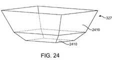
- the coupling elementhas an internal bore sized to receive the shank portion of the fixation element and a pyramid-shaped seat for supporting the head portion of the fixation element.
- the coupling elementis adapted to receive a stabilizer rod.
- the compression nutis engagable with the coupling element and is adapted to rotatingly move distally into the coupling element to translate a force to the head portion through the rod and the saddle such that the head portion is forced against the seat of the coupling element to prevent relative movement between the fixation element and the coupling element.
- FIG. 1 ais an illustration of a human vertebral column.
- FIG. 1 bis a superior view of a typical human vertebra.
- FIG. 1 cis a lateral view of the vertebra depicted in FIG. 1 b.
- FIG. 2is an illustration of a set of pedicle screws implanted into a human vertebral column
- FIG. 3shows an exploded view of a bone fixation assembly according to one embodiment.
- FIG. 4shows a cross-sectional view of the bone fixation assembly depicted in FIG. 3 .
- FIG. 5 ashows a cross-sectional view of a bone fixation assembly according to another embodiment.
- FIG. 5 bis a magnified view of region 5 b depicted in FIG. 5 a.
- FIG. 6 ais a side view of the bottom saddle depicted in FIGS. 3 , 4 and 5 .
- FIG. 6 bis a perspective view of the bottom saddle depicted in FIGS. 3 , 4 and 5 .
- FIG. 7is a side elevation view of the bottom saddle depicted in FIGS. 6 a and 6 b as it is loaded into a bone fixation assembly.
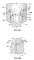
- FIG. 8 ashows a cross-sectional view of a bone fixation assembly according to another embodiment.
- FIG. 8 bis a magnified view of region 8 b depicted in FIG. 8 a.
- FIG. 9shows an exploded view of the bone fixation assembly depicted in FIG. 8 .
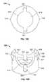
- FIGS. 10 a - 10 dshow various views of the saddle depicted in the bone fixation assembly depicted in FIGS. 8 and 9 .
- FIG. 11is a perspective view of the coupling element depicted in the bone fixation assembly depicted in FIGS. 8 and 9 .
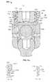
- FIG. 12 ais a cross-sectional view of a bone fixation assembly according to another embodiment.
- FIG. 12 bis a magnified view of region 12 b depicted in FIG. 12 a.
- FIG. 13 ais a cross-sectional view of a bone fixation assembly according to another embodiment.
- FIG. 13 bis a magnified view of region 13 b depicted in FIG. 13 a.
- FIG. 14 ais a side view of the saddle depicted in the bone fixation assembly depicted in FIGS. 13 a and 13 b.
- FIG. 14 bis a perspective view of the saddle depicted in FIG. 14 a.
- FIG. 15 ais a cross-sectional view of a bone fixation assembly according to another embodiment.
- FIG. 15 bis a cross-sectional view of the external threads of the compression nut depicted in FIG. 15 a.
- FIG. 15 cis a cross-sectional view of the internal threads of the coupling element depicted in FIG. 15 a.
- FIG. 16is a cross-sectional view of a compression element of a bone fixation assembly according to one embodiment.
- FIG. 17 ais a cross-sectional view of a compression element of a bone fixation assembly according to another embodiment.
- FIG. 17 bis a cross-sectional view of the external threads of the compression nut depicted in FIG. 17 a.
- FIG. 17 cis a cross-sectional view of the internal threads of the coupling element depicted in FIG. 17 a.
- FIG. 18 ais a cross-sectional exploded view of a compression nut and top saddle according to one embodiment.
- FIG. 18 bis a cross-sectional view of the compression nut and top saddle depicted in FIG. 18 a.
- FIG. 19 ais a cross-sectional exploded view of a compression nut and top saddle according to another embodiment.
- FIG. 19 bis a cross-sectional view of the compression nut and top saddle depicted in FIG. 19 a.
- FIG. 20 ashows a cross-sectional view of the bone fixation assembly according to another embodiment.
- FIG. 20 bis a magnified view of region 20 b depicted in FIG. 20 a.
- FIG. 20 cshows an exploded view of a coupling element according to one embodiment.
- FIG. 21 ashows a cross-sectional view of the bone fixation assembly according to another embodiment.
- FIG. 21 bis a magnified view of region 21 b depicted in FIG. 21 a.
- FIG. 21 cshows a conically-shaped seat of the coupling element according to one embodiment.
- FIG. 22shows a pyramid-shaped seat of the coupling element according to one embodiment.
- FIG. 23 ashows another pyramid-shaped seat of the coupling element.
- FIG. 23 bshows another pyramid-shaped seat of the coupling element.
- FIG. 24shows another pyramid-shaped seat of the coupling element.
- Bone stabilization assembliesare commonly used throughout the skeletal system to stabilize broken, fractured, diseased or deformed bones.
- pedicle screw systemsare particularly well adapted for the fixation and manipulation of the bones of the vertebral column.
- a vertebral pedicleis a dense stem-like structure that projects from the posterior of a vertebra. There are two pedicles per vertebra that connect to other structures (e.g. lamina, vertebral arch). The location of a pedicle P is illustrated in FIGS. 1 b and 1 c , which illustrate a typical vertebral column, a superior view of a typical vertebra, and a lateral view of a typical vertebra, respectively.
- Bone screwshave been used in spinal instrumentation since the 1960s.
- a pedicle screwis a particular type of bone screw designed for implantation into a vertebral pedicle.
- Monoaxial pedicle screwsare still used quite often, but the current standard for implantation is a polyaxial pedicle screw made of titanium or titanium alloy. Titanium alloy is useful, because it is highly resistant to corrosion and fatigue, and is MRI compatible. The screw is threaded and the head is moveable, allowing it to swivel so as to defray vertebral stress.
- Polyaxial pedicle screw lengthsrange from about 30 mm to about 60 mm with diameters ranging from about 5.0 mm to about 8.5 mm.
- Pedicle screwsare used to correct deformity, and or to treat trauma. They can be used in instrumentation procedures to affix rods and plates to the spine. They can also be used to immobilize part of the spine to assist fusion by holding bony structures together. Although pedicle screws are most often used in the lumbar (lumbosacral) spine, they can be implanted in the thoracic and sacral vertebra. The surgeon uses fluoroscopy, conventional x-ray, and sometimes computer-assisted visualization to determine the depth and angle for screw placement. A receiving channel is drilled and the screw is inserted. The screws themselves do not fixate the spinal segment, but act as firm anchor points that can then be connected with a rod. As shown in FIG.
- the screwsare placed down the small bony tube created by the pedicle on each side of the vertebra, between the nerve roots. This allows the screws to grab into the bone of the vertebral body, giving them a solid hold on the vertebra.
- the screwsare placed, one in each of the two pedicles of each vertebra, they are attached to metal rods that connect the screws together.
- the screwsare placed at two or more consecutive spine segments (e.g., lumbar segment 5 and 6) and connected by the rods.
- a poly-axial pedicle screw assemblyincludes a tulip-like coupling element that can be coupled to a fixation element, such as, for example, a screw with a head that removably mates with the coupling element.
- the coupling element and fixation elementare configured to be coupled to an elongate stabilizer, such as a rod, that is positioned between a top and a bottom saddle or between a compression member and bottom saddle.
- a compression membersuch as a compression nut, is configured to mate with the coupling element and provides a compressive force to the top and bottom saddles or to the top of the elongate stabilizer rod to secure the elongate stabilizer rod therebetween.
- the top and bottom saddlesare movably positioned within the coupling element such that they can gradually reposition into a secure engagement with the stabilizer as the compression member provides the compressive force.
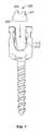
- a pedicle screw assemblyincludes an anchor 105 having a fixation element 110 that is removably coupled to a coupling element 115 .
- the assemblyfurther includes a stabilizer, such as an elongate rod 120 , that can be compressively secured to the anchor 105 , as described below.
- the fixation element 110can be coupled to a skeletal structure, such as a spinal vertebra by being drilled or screwed into, e.g., a pedicle of a vertebra.
- the coupling element 115is used to couple the fixation element 110 to the stabilizer, which can be coupled to multiple fixation elements using additional coupling elements 115 .
- the fixation element or pedicle screw 110can include, for example, an elongate screw having a threaded shank portion 205 with external threads that can be screwed into the bone structure, e.g., pedicle, of a vertebra.
- a head 210is positioned at the upper end of the shank portion 205 .
- the head 210has a shape, such as a rounded shape, that is configured to mate with a correspondingly-shaped seat structure in the coupling element 115 , as described below.
- a drive coupler, such as a drive cavity 215is located within or on the head 210 of the fixation element 110 .
- the drive cavity 215has a shape that is configured to receive a device that can impart rotational movement to the fixation element 110 in order to screw the fixation element 110 into a bone structure.
- the drive cavity 215can have a hexagonal shape that is configured to receive therein an allen-style wrench.
- the drive couplerneed not be a cavity that mates with an allen-style wrench and that other types of drive couplers can be used.
- the fixation element 110can be in forms other than a shank, including, for example, a hook or clamp. Indeed, it should be appreciated that any structure or component configured for attachment to a bone structure can be used in place of the shank portion of the fixation element.
- the coupling element 115is configured to receive the fixation element 110 and the elongate rod 120 .
- the coupling element 115has an internal bore 305 that extends through the coupling element 115 along an axis A (the axis A is shown in FIGS. 3 and 4 ).
- the internal bore 305is sized to receive at least the shank portion 205 of the fixation element therethrough.
- a pair of laterally-opposed, upwardly extending projections 310is separated by the bore 305 .
- the projections 310have internal, threaded surfaces.
- a pair of U-shaped channels 315extends through the coupling element for receiving therein the rod 120 , which extends along an axis that is transverse to the axis A of the bore 305 .
- the upper ends of the projections 310define an entry port that is sized to receive therein a compression nut 410 , as described below.
- the compression nut 410is described herein as having outer threads that are configured to mate with the inner threads on the opposed inner surfaces of the projections 310 of the coupling element 115 .
- the entry portis sized and shaped to facilitate an easy entry of the compression nut 410 into or over the projections 310 of the coupling element.
- a bottom saddle 320 and a top saddle 325are configured to be positioned within the coupling element 115 .
- the saddleseach define a contact surface 330 (shown in FIG. 3 ) that has a contour selected to complement a contour of the outer surface of the rod 120 .
- the contact surfaces 330have rounded contours that complement the rounded, outer surface of the rod 120 .
- the contact surfaces 330can have any shape or contour that complement the shape and contour of the rod 120 .
- the contact surfaces 330can also be roughed, serrated, ribbed, or otherwise finished to improve the frictional engagement between the saddles 320 , 325 and the rod.
- the rod 120can also be correspondingly roughed, serrated, ribbed, or otherwise finished to further improve the frictional engagement between saddles 320 , 325 and the rod.
- the complementing shapes and contours between the contact surfaces 330 and rod 120provide a maximum amount of contact area between the saddles 320 , 325 and rod 120 .
- the rod 120is shown having a rounded or convex outer surface.
- the contact surfaces 330 of the saddles 320 , 325are correspondingly rounded or concave such that the elongate rod 120 can fit snug between the saddles 320 , 325 with the contact surfaces 330 of the saddles 320 , 325 providing a wide area of contact with the outer surface of the elongate rod 120 .
- the contour and shape of the contact surfaces 330can be varied to match any contour of the outer surface of the elongate rod 120 or in any manner to maximize the amount of grip between the saddles and the elongate rod.
- the shank portion 205 of the fixation element 110is inserted through the bore 305 in the coupling element 115 .
- the rounded head 210abuts against and sits within a correspondingly-shaped seat 327 in the bottom of the coupling element 115 in a ball/socket manner, as shown in the cross-sectional view of FIG. 4 .
- the seat 327can have a rounded shape that is configured to provide a secure fit between the head 210 and the coupling element 115 . Because the seat 327 is rounded, the head 210 can be rotated within the seat 327 to move the axis of the shank portion 205 to a desired orientation relative to the coupling element 115 and thereby provide a poly-axial configuration.
- the fixation element 110With the fixation element 110 seated in the coupling element 115 , an operator can position the assembly relative to a bone structure such as a vertebra.
- a drive devicesuch as an Allen wrench
- the bottom saddle 320has an internal bore that is sized to receive therethrough the drive device to provide access to the head 210 of the fixation element 110 .
- the rod 120is loaded into the coupling element 115 by inserting the rod downwardly between the projections 310 through the u-shaped channels 315 , as shown in FIG. 3 .
- the outer surface of the rod 120will eventually abut and sit against the corresponding rounded contact surface 330 of the bottom saddle 320 .
- the compression nut 410 and attached upper saddle 325are then threaded downward into the coupling element 115 by mating the external threads on the compression nut 410 with the internal threads on the projections 310 of the coupling element 115 .
- the compression nut 410can be threaded downward until the rod 120 is compressed between the top and bottom saddles, with the compression nut 410 providing the compression force.
- the coupling element 115has an entry port for the compression nut 410 that facilitates entry or coupling of the compression nut 410 into the coupling element 115 .
- the entry portis defined by the upper edges of the projections 310 .
- the entry porthas a structure that guides the compression nut into a proper engagement with the coupling element 115 .
- one or more large chamfers 425are located on the upper, inner edge of the projections 310 of the coupling element 115 to provide ease of entry for the compression nut 410 into the coupling element 115 .
- the chamfers 425are angled with the angle being in the range of thirty degrees to sixty degrees relative to vertical axis A, although the angle can vary. The chamfers 425 guide the compression nut 410 into proper alignment with the coupling element 115 such that the threads on the compression nut properly engage the threads on the opposed projections 310 without any cross-threading.
- the compression nut 410is then threaded downwardly by repeatedly rotating the compression nut 410 about a 360 degree rotation. As the compression nut 410 lowers into the coupling element, the rounded contact surface 330 of the top saddle 325 abuts the rod 120 and compresses the rod 120 against the rounded contact surface 330 of the bottom saddle 320 , as shown in FIG. 4 .
- the bottom saddle 320has a floating arrangement with the coupling element 115 and the top saddle 325 is movable and rotatable relative to the compression nut 410 . This permits the saddles to gradually reposition themselves into a secure purchase with the rod 120 as the compression nut 410 moves downward.
- the contact surfaces 330 of the saddles 320 , 325provide a continuous and maximized area of contact between the saddles 320 , 325 and the rod 120 for a secure and tight fit therebetween.
- the top saddle 325is shaped so that opposed wings or protrusions 329 are located on opposed sides of the top saddle 325 (see FIGS. 16-17 ).
- the opposed protrusions 329are positioned on either side of the rod 120 so as to automatically guide the saddle 325 into alignment with the rod 120 as the saddle 325 lowers onto the rod. Because the top saddle 325 can freely rotate as the compression nut lowers onto the rod 120 , the protrusions 329 will abut opposed sides of the rod 120 as the top saddle 325 is lowered into the coupling element 115 .
- the top saddle 325thus self-aligns into a secure engagement with the rod 120 as the top saddle 325 is lowered onto the rod 120 .
- the protrusions 329 of the top saddleare formed by a concave contour of the top saddle contact surface 330 . It should be appreciated that the protrusions 329 need not be formed from curved surfaces, but can also be formed from straight surfaces. Moreover, the protrusions 329 need not be formed from a continuous, elongated surface, but can rather comprise one or more discrete protrusions, such as spikes, that extend downwardly from the top saddle 325 .
- the downward force of the compression nut 410is transferred to the bottom saddle 320 via the top saddle 325 and the rod 120 .
- the head 210is thereby pressed downward into the seat 327 in a fixed orientation. In this manner, the position of the fixation element 110 relative to the coupling element 115 is fixed. That is, the head 210 of the fixation element 110 is pressed downward into the seat 327 of the coupling element 115 with a force sufficient to lock the position of the head 210 relative to the coupling element 115 .
- the compression nut 410can be tightened to provide a sufficient downward force that locks the positions of the saddles 320 , 325 relative to the coupling element 115 and the elongate rod 120 .
- the compression nut 410thereby provides a downward force that locks the relative positions of the elongate rod 120 , saddles 320 , 325 , coupling element 115 , and fixation element 110 .
- the upper portion of the opposed projections 310 of the coupling elementcan be snapped off at a predetermined location along the length of the projections 310 .
- inner threadsare located on the opposed inner faces of the projections 310 .
- the threadsextend downwardly along the projections 310 to a depth that is sufficient to provide secure engagement between the threads on the projections 310 and the threads on the compression nut 410 when the compression nut 410 is fully tightened. It should be appreciated that the threads do not have to extend to a depth below the upper surface (identified by line U in FIG. 4 ) of the rod 120 when the rod 120 is positioned in the coupling element 115 . In one embodiment, the threads extend to a depth that is above the upper surface (identified by line U) of the rod 120 .
- the top saddle 325provides a spacing between the rod 120 and the compression nut 410 , which permits such thread depth.
- the bottom saddle 320has an internal bore 316 that axially aligns with the bore 305 in the coupling element 115 when the bottom saddle 320 is placed in the coupling element 115 .
- the bottom saddle 320has a cylindrical outer surface 326 forming a pair of opposed walls 321 separated by the internal bore 316 and a rod-receiving region 323 .
- Outer surfaces of the opposed walls 321include opposing projections 335 that extend laterally from the walls 321 .
- Each of the projections 335aligns with a corresponding hole or aperture 340 (shown in FIGS. 3 and 4 ) that extends through the coupling element 115 .
- the opposed wallsare generally perpendicular to the base 324 of the saddle 320 , as indicated by angle ⁇ shown in FIG. 6A .
- the bottom saddle 320is secured within the coupling element 115 by positioning the saddle between the projections 310 such that each projection 335 in the bottom saddle 320 is inserted into a corresponding aperture 340 in the coupling element 115 .
- the bottom saddle 320is inserted into the coupling element 115 by forcing the saddle 320 down through the projections 310 of the coupling element.
- the distance Xdepicted in FIG. 6 a , represents the distance between the outer ends 336 of the projections 335 .
- Distance Ydepicted in FIG. 4 , represents the distance between the inner surfaces 311 of the projections 310 of the coupling element 115 .
- Distance Xis slightly greater than distance Y.
- saddle 320must be inserted into the coupling element 115 by forcing it downward through the projections 310 against which the projections 335 will scrape. Once the saddle 320 has been pushed down far enough inside the coupling element 115 that the projections 335 line up with the corresponding apertures 340 , the projections 335 will pop into the apertures 340 .
- the projections 335are shaped to facilitate insertion and retention of the saddle 320 within the coupling element 115 . As shown in FIGS. 6 a and 6 b , the projections 335 have a flat or horizontal proximal surface 338 , a rounded side or lateral surface 336 , and an angled or ramped distal surface 337 .
- the flat proximal surface 338prevents the saddle 320 from sliding out of the coupling element 115 in the proximal direction.
- the angled or ramped distal surface 337allows the saddle to be guided into the coupling element.
- the opposed walls 321can be slightly flexible so that during insertion the walls 321 flex inward toward each other to allow the saddle 320 to be pushed down into the coupling element 115 . Once the projections 335 of the saddle 320 reach the apertures 340 of the coupling element, the walls 321 flex back to their natural position and the projections 335 pop into the apertures 340 .
- the apertures 340can be round, rectangular, square, oval or any other shape that can receive the projections 335 in a manner that allows the saddle 320 to float in the coupling element 115 .
- the projections 335can be cylindrical, conical, block (rectangular or square), or any other shape that fits within the apertures 340 in a manner that allows the saddle to float in the coupling element 115 .
- the saddle 320can be inserted into the coupling element 115 in the manner shown in FIG. 7 .
- the saddle 320is first rotated so that the walls 321 are aligned with the U-shaped channels 315 rather than the projections 310 of the coupling element 115 .
- the diameter of the cylindrical outer surface 326 of the saddle 320is slightly smaller than the distance Y between the inner surfaces 311 of the projections 310 of the coupling element 115 so that the saddle 320 slides freely into the coupling element 115 without any significant frictional engagement between the saddle 320 and coupling element 115 .
- the saddle 320is rotated about 90° until the projections 335 pop into the apertures 340 .
- the projections 335will scrape against the inner surfaces 311 of the projections 310 .
- the rounded lateral surface 336 of the projections 335facilitate the rotation of the saddle 320 .
- the diameter of the aperture 340can be greater than the distance between the proximal end 338 of the projection 335 and the distal end 337 of the projection 335 by between about 1.0 mm and about 3 mm. In one embodiment, the diameter of the aperture 340 is about 1.0 mm greater than the distance between the proximal end 338 of the projection 335 and the distal end 337 of the projection 335 , allowing about 1.0 mm of play between the bottom saddle 320 and the coupling element 115 . The diameter of the cylindrical outer surface 326 of the bottom saddle is also less than distance Y between the projections 310 .
- the bottom saddle 320can “float” in the coupling element 115 such that the position and the orientation of the bottom saddle 320 can be varied slightly. That is, the bottom saddle 320 can be moved slightly upward or downward and from side to side when mounted in the coupling element 115 . The bottom saddle 320 can also rotate slightly when mounted in the coupling element 115 . Thus, the bottom saddle 320 can movingly adjust into a secure engagement with the elongate rod 120 when compressed against the elongate rod 120 during assembly, as described below. It can also movingly adjust into a secure engagement with the head portion 210 of the fixation element 110 when pushed down against the head portion 210 by the elongate rod 120 .
- the coupling element 115has a channel 440 rather than apertures 340 .
- Each of the projections 310 of the coupling element 115has a channel 440 bored into it, and the channels 440 are aligned with one another and face one another as shown in FIG. 5 a .
- the projections 435 of the saddle 320can be mated with the channels 440 so as to retain the bottom saddle 320 within the coupling element 115 .
- the saddle 320 shown in FIGS. 5 a and 5 bcan have the same projections 335 as shown in FIGS. 6 a and 6 b , or it can have square or rectangular block projections 435 as shown in FIGS. 5 a and 5 b.
- the lateral ends 436 of the saddle 320do not make contact with the lateral surface 441 of the channel 440 .
- the distance between the lateral surfaces 441 of the two projections 310is greater than the distance between the lateral ends 436 of the projections 435 of the bottom saddle 320 .
- the height of the projections 435(i.e., the distance between the proximal surface 438 and distal surface 437 of the projections 435 ) is between about 1.0 mm and 3.0 mm less than the height of the channels 440 (i.e., the distance between the proximal inner surface 448 and distal inner surface 447 of the channels 440 ).
- the height of the channels 440is about 1.0 mm greater than the height of the projections 435 , allowing about 1.0 mm of play between the bottom saddle 320 and the coupling element 115 .
- the diameter of the cylindrical outer surface 326 of the bottom saddleis also less than distance Y between the projections 310 .
- the bottom saddle 320can “float” in the coupling element 115 such that the position and the orientation of the bottom saddle 320 can be varied slightly. That is, the bottom saddle 320 can be moved slightly upward or downward and from side to side when mounted in the coupling element 115 . The bottom saddle 320 can also rotate slightly when mounted in the coupling element 115 . Thus, the bottom saddle 320 can movingly adjust into a secure engagement with the elongate rod 120 when compressed against the elongate rod 120 during assembly, as described below. It can also movingly adjust into a secure engagement with the head portion 210 of the fixation element 110 when pushed down against the head portion 210 by the elongate rod 120 .
- the saddle 320can be inserted into the coupling element 115 in a manner similar to that shown in FIG. 7 .
- the saddle 320is first rotated so that the walls 321 are aligned with the U-shaped channels 315 rather than the projections 310 of the coupling element 115 .
- the diameter of the cylindrical outer surface 326 of the saddle 320is slightly smaller than the distance Y between the inner surfaces 311 of the projections 310 of the coupling element 115 so that the saddle 320 slides freely into the coupling element 115 without any significant frictional engagement between the saddle 320 and coupling element 115 .
- the saddle 320is rotated until the projections 435 slide into the channels 440 .
- the channels 440can extend along the entire circumference or length of the inner surfaces 311 of the projections 435 so that the projections 435 slide into the channels 440 without running into or contacting the projections 435 .
- FIGS. 8-11describe another embodiment, which differs from the other embodiments only with respect to the bottom saddle 520 and retention means for the bottom saddle 520 within the coupling element 115 .
- the bottom saddle depicted in FIGS. 8-11is designed to permit the opposed walls 521 to tilt toward one another in response to compression forces, and to spring back to their original or resting parallel orientation in the absence of compression forces.
- the bottom saddle 520has an internal bore 516 that axially aligns with the bore 305 in the coupling element 115 when the bottom saddle 520 is placed in the coupling element 115 .
- the bottom saddle 520has a cylindrical outer surface 526 forming a pair of opposed walls 521 separated by the internal bore 516 and a rod-receiving region 523 .
- Opposed walls 521are generally perpendicular to the base 524 of the bottom saddle 520 , as indicated by angle ⁇ shown in FIG. 10A .
- Outer surfaces of the opposed walls 521include opposing projections 535 that extend laterally from the walls 521 .
- Each of the projections 535aligns with a corresponding cavity 540 (shown in FIG. 11 ) that is carved into each of the projections 310 of the coupling element 115 .
- the opposed walls 521 of the saddle 520are connected to one another by a pair of flexible joints 580 that permit the opposing walls 521 to tilt toward one another in response to compression forces, and to spring back to their original or resting parallel orientation in the absence of compression forces.
- the flexible joints 580are formed by a pair of keyhole slots 581 carved into the cylindrical portion 526 of the bottom saddle 520 .
- the keyhole slots 581are opposite each other and are each aligned about 90° away from each of the projections 535 .
- the flexible joints 580are opposite each other and are each aligned about 90° away from each of the projections 535 .
- the keyhole slots 581 and the flexible joints 580permit the opposed walls 521 to be squeezed toward one another in response to a compressive force and to spring back into a resting parallel orientation in the absence of a compressive force.
- the bottom saddle 520is secured within the coupling element 115 by positioning the saddle between the projections 310 such that each projection 535 in the bottom saddle 520 is inserted into a corresponding cavity 540 in the coupling element 115 .
- the bottom saddle 520is inserted into the coupling element 115 by forcing the saddle 520 down through the projections 310 of the coupling element.
- the distance Xdepicted in FIG. 8 a , represents the distance between the lateral surface 536 of the projections 535 .
- Distance Ydepicted in FIG. 8 a , represents the distance between the inner surfaces 311 of the projections 310 of the coupling element 115 .
- Distance Xis slightly greater than distance Y.
- the saddle 520must be inserted into the coupling element 115 by forcing it downward through the projections 310 against which the projections 535 will scrape.
- the opposed walls 521 of the saddle 520can be squeezed toward one another because of the flexible joints 580 and keyhole slots 581 (shown in FIG. 10 b ).
- the projections 535will pop into the cavities 540 .
- the projections 535are shaped to facilitate insertion and retention of the saddle 520 within the coupling element 115 . As shown in FIGS.
- the projections 535have a flat or horizontal proximal surface 538 , a rounded side or lateral surface 536 , and an angled or ramped distal surface 537 (alternatively, the distal surface 537 can be horizontal or flat).
- the flat proximal surface 538prevents the saddle 520 from sliding out of the coupling element 115 in the proximal direction.
- the angled or ramped distal surface 537allows the saddle to be guided into the coupling element 115 .
- the opposed walls 521are flexible so that during insertion the walls 521 flex inward toward each other to allow the saddle 520 to be pushed down into the coupling element 115 .
- the cavities 540can be round, rectangular, square, oval or any other shape that can receive the projections 535 in a manner that allows the saddle 520 to float in the coupling element 115 .
- the projections 535can be cylindrical, conical, block (rectangular or square), or any other shape that fits within the cavities 540 in a manner that allows the saddle 520 to float in the coupling element 115 .
- the saddle 520can be inserted into the coupling element 115 in the manner shown in FIG. 7 .
- the saddle 520is first rotated so that the walls 521 are aligned with the U-shaped channels 315 rather than the projections 310 of the coupling element 115 .
- the diameter of the cylindrical portion 526 of the saddle 520is slightly smaller than the distance Y between the inner surfaces 311 of the projections 310 of the coupling element 115 so that the saddle 520 slides freely into the coupling element 115 without any significant frictional engagement between the saddle 520 and coupling element 115 .
- the saddle 520is rotated about 90° until the projections 535 pop into the cavities 540 .
- the projections 535will scrape against the inner surfaces 311 of the projections 310 .
- the rounded lateral surface 536 of the projections 535facilitate the rotation of the saddle 520 .
- the lateral ends 436 of the saddle 320do not make contact with the lateral surface 441 of the cavities 440 .
- the distance between the lateral surfaces 441 of the two projections 310is greater than the distance between the lateral ends 436 of the projections 435 of the bottom saddle 320 .
- the height of the projections 435(i.e., the distance between the proximal surface 438 and distal surface 437 of the projections 435 ) is between about 1.0 mm and 3.0 mm less than the height of the channels 440 (i.e., the distance between the proximal inner surface 448 and distal inner surface 447 of the channels 440 ).
- the height of the channels 440is about 1.0 mm greater than the height of the projections 435 , allowing about 1.0 mm of play between the bottom saddle 320 and the coupling element 115 .
- the diameter of the cylindrical portion 326 of the bottom saddleis also less than distance Y between the projections 310 .
- the bottom saddle 320can “float” in the coupling element 115 such that the position and the orientation of the bottom saddle 320 can be varied slightly. That is, the bottom saddle 320 can be moved slightly upward or downward and from side to side when mounted in the coupling element 115 . The bottom saddle 320 can also rotate slightly when mounted in the coupling element 115 . Thus, the bottom saddle 320 can movingly adjust into a secure engagement with the elongate rod 120 when compressed against the elongate rod 120 during assembly, as described below. It can also movingly adjust into a secure engagement with the head portion 210 of the fixation element 110 when pushed down against the head portion 210 by the elongate rod 120 .
- the bottom saddle 520is the same or substantially the same as bottom saddle 520 shown in FIGS. 8 a - 10 d .
- the bottom saddle 520is secured within the coupling element 115 by positioning the saddle between the projections 310 such that each projection 535 in the bottom saddle 520 is inserted into a corresponding cavity 940 in the coupling element 115 .
- the bottom saddle 520is inserted into the coupling element 115 by forcing the saddle 520 down through the projections 310 of the coupling element.
- the distance Xdepicted in FIG. 12 a , represents the distance between the outer ends 436 of the projections 535 .
- Distance Tdepicted in FIG.
- the projections 535are shaped to facilitate insertion and retention of the saddle 520 within the coupling element 115 as described with respect to FIGS. 10 c and 10 d above.
- the opposed walls 521are flexible so that during insertion the walls 521 flex inward toward each other to allow the saddle 520 to be pushed down into the coupling element 115 . Once the projections 535 of the saddle 520 reach the cavities or indentations 940 of the coupling element 115 , the walls 521 flex back to their natural or resting position and the projections 535 pop into the cavities 940 .
- the cavities 940are aligned with one another, but they are not parallel with one another. Instead, as shown in more detail in FIG. 12 b and further described below, the cavities 940 are sloped or ramped toward one another in the distal direction.
- the cavities 940each have a proximal region, which is near the top end of the coupling element 115 , a middle region distal the proximal region, and a distal region, which is distal the middle region.
- the distance Z between the proximal regions of the cavities 940is greater than the distance X between the outer ends 536 of the projections 535 , and the distance X is greater than the distance Y between the distal regions of the cavities 940 .
- the proximal region of the cavities 940each includes a ridge with a drop-off as shown in FIG. 12 b .
- a middle region of the cavities 940distal the proximal region, forms a ramp that is sloped inward toward a distal direction, wherein the proximal end of the ramp starts at the drop-off and a distal end of the ramp terminates in a distal region that joins the ramp to the inner surface 311 of the wall of the coupling element 115 .
- the projections 535do not make contact with the inner surface 941 of the cavities. Thus, there is no axial force or frictional engagement between the projections 535 and the inner surface 941 of the cavities 940 in the proximal region. This permits some play between the bottom saddle 520 and the coupling element 115 when the bottom saddle is in the proximal region of the cavities 940 .
- the height of the projections 535i.e., the distance between the proximal surface 538 and distal surface 537 of the projections 535 ) is between about 1.0 mm and 3.0 mm less than the height of the proximal region of the cavities 940 .
- the height of the proximal region of the cavities 940is about 1.0 mm greater than the height of the projections 535 , allowing about 1.0 mm of play between the bottom saddle 520 and the coupling element 115 when the projections are situated in the proximal region of the cavities 940 .
- the diameter of the cylindrical portion 526 of the bottom saddleis also less than distance Y between the projections 310 . These dimensions permit the bottom saddle 520 to “float” in the coupling element 115 such that the position and the orientation of the bottom saddle 520 can be varied slightly while the projections 535 are situated in the proximal region of the cavities 940 .
- the bottom saddle 520can be moved slightly upward or downward and from side to side when mounted in the coupling element 115 when the projections 535 are situated within the proximal region of the cavities 940 .
- the bottom saddle 520can also rotate slightly when mounted in the coupling element 115 when the projections 535 are situated within the proximal region of the cavities 940 .
- the distance between the inner surfaces 941which are in opposite projections 310 , becomes smaller because of the sloped ramps.
- the projections 535make contact with the inner surfaces 941 of the cavities 940 .
- inward axial forcesare exerted on the projections 535 and the walls 521 are squeezed into frictional engagement with the sloped ramps.
- the frictional engagement between the opposing projections 535 and the distal region of the opposing cavities 940maintains the saddle 520 in frictional engagement with the head portion 210 of the fixation element 110 to prevent relative movement between the fixation element 110 and the coupling element 115 when the stabilizer rod is disengaged from the saddle 520 and the saddle 520 engages the fixation element 110 .
- the fixation element 110 and the coupling element 115are still manually movable relative to each other in opposition to the frictional engagement when the stabilizer rod is disengaged from the saddle.
- FIGS. 13A-14Bdescribe another embodiment, which differs from the previous embodiments only with respect to the bottom saddle 1220 and retention means for the bottom saddle 1220 within the coupling element 115 .
- the bottom saddle 1220 depicted in FIGS. 13A-14Bis designed to permit the opposed walls 1221 to tilt toward one another in response to compression forces, and to spring back to their original or resting parallel orientation in the absence of compression forces.
- the bottom saddle 1220does not have projections that extend laterally from its opposed walls 1221 . Instead, the outer surface 1226 of the opposed walls are at an angle ⁇ , as shown in detail in FIGS. 14A and 14B .
- the walls 1221are not parallel to one another when the walls 1221 are in a resting or uncompressed state. Instead, they extend away from one another from bottom to top such that the angle ⁇ between the base 1224 of the bottom saddle 1220 and the outer surface of the walls 1226 is an obtuse angle or greater than 90° when the walls 1221 are in a resting or uncompressed state.
- the bottom saddle 1220has an internal bore 1216 that axially aligns with the bore 305 in the coupling element 115 when the bottom saddle 1220 is placed in the coupling element 115 .
- the bottom saddle 1220has a frustoconical outer surface 1226 forming a pair of opposed walls 1221 separated by the internal bore 1216 and a rod-receiving region 1223 . Outer surfaces of the opposed walls 1221 are angled toward one another as explained above.
- the opposed walls 1221 of the saddle 1220are connected to one another by a pair of flexible joints 1280 that permit the opposing walls 1221 to tilt toward one another in response to compression forces, and to spring back to their original or resting parallel orientation in the absence of compression forces.
- the flexible joints 1280are formed by a pair of keyhole slots 1281 carved into the frustoconical portion 1226 of the bottom saddle 1220 .
- the keyhole slots 1281are opposite each other.
- the keyhole slots 1281 and the flexible joints 1280permit the opposed walls 1221 to be squeezed toward one another in response to a compressive force and to spring back into a parallel orientation in the absence of a compressive force.
- the bottom saddle 1220is secured within the coupling element 115 by positioning the saddle between the projections 310 such that each of the walls 1221 of the bottom saddle is inserted into a corresponding retention region 1240 in the coupling element 115 .
- the bottom saddle 1220is inserted into the coupling element 115 by forcing the saddle 1220 down through the projections 310 of the coupling element.
- the distance Xdepicted in FIG. 13 a , represents the distance between the outer surface 1226 of walls 1221 in the proximal region 1235 of the walls.
- Distance Tdepicted in FIG.
- 13 arepresents the distance between the inner surfaces of the projections 310 of the coupling element 115 in a region proximal the retention region of the projections 310 .
- the inner surfaces of the projections 310 in a region proximal the retention regionform a cylinder, such that the walls are parallel to one another.
- Distance Xis slightly greater than distance T. Therefore, the saddle 1220 must be inserted into the coupling element 115 by forcing it downward through the projections 310 against which the proximal region 1235 of the walls 1221 will scrape.
- the opposed walls 1221 of the saddle 1220can be squeezed toward one another because of the flexible joints 1280 and keyhole slots 1281 .
- the retention region 1240 of the coupling element 115begins at a proximal ridge 1241 that forms a pop-out with inner surfaces 311 .
- the inner surfaces 311are not parallel to one another. Instead, they are angled toward one another from a proximal to a distal direction.
- the inner surfaces 311can be parallel with the opposed walls 1221 of the saddle such that opposed walls 1221 and inner surfaces 311 are at the same angle relative to the base 1224 of the saddle. For example, if the walls 1221 are at an angle of about 100° to the base 1224 , then the inner surfaces 311 can also be at an angle of about 100° relative to the base 1224 of the saddle.
- the inner surfaces 311can form a greater angle relative to the base 1224 than the opposed walls 1221 , so that the opposed walls 1221 are not parallel to the base 1224 .
- the inner surfaces 311can be at an angle of, e.g., 105° to the base.
- the retention regions 1240 of the projections 310each have a proximal region, which is near the top end of the coupling element 115 just distal the ridge 1241 , a middle region distal the proximal region, and a distal region, which is distal the middle region.
- the distance X between the proximal regions of the retention region 1240is greater than the distance X between the outer proximal region 1235 of the walls 1221 .
- Distance Zdecreases in the distal direction, such that distance Y is less than distance X and distance Z.
- the walls 1221flex back to their natural or resting position and pop into the proximal region of the retention region 1240 where there is no compressive force against the walls 1221 .
- the saddle 1220can be inserted into the coupling element 115 in the manner shown in FIG. 7 and described above.
- the proximal region 1235 of the walls 1221do not make contact with the inner surface 311 of the proximal regions of the retention regions 1240 .
- These dimensionspermit the bottom saddle 1220 to “float” in the coupling element 115 such that the position and the orientation of the bottom saddle 1220 can be varied slightly while the proximal regions 1235 s are situated in the proximal region of the retention region 1240 .
- the bottom saddle 1220can be moved slightly upward or downward and from side to side when mounted in the coupling element 115 when the proximal regions 1235 are situated within the proximal region of the retention region 1240 .
- the bottom saddle 1220can also rotate slightly when mounted in the coupling element 115 when the proximal regions 1235 are situated within the proximal region of the retention region 1240 .
- the distance between the inner surfaces 311which are opposite projections 310 , becomes smaller because of the angled or sloped inner surfaces 311 .
- the proximal regions 1235make contact with the inner surfaces 311 of the retention region 1240 .
- inward axial forcesare exerted on the proximal regions 1235 of the walls 1221 , and the walls 1221 are squeezed into frictional engagement with the sloped surfaces 311 of the retention region 1240 .
- the frictional engagement between the proximal regions 1235 and the distal region of the retention region 1240maintains the saddle 1220 in frictional engagement with the head portion 210 of the fixation element 110 to prevent relative movement between the fixation element 110 and the coupling element 115 when the stabilizer rod is disengaged from the saddle 1220 and the saddle 1220 engages the fixation element 110 .
- the fixation element 110 and the coupling element 115are still manually movable relative to each other in opposition to the frictional engagement when the stabilizer rod is disengaged from the saddle 1220 .
- the top saddle 325is rotatingly mounted within a compression nut 410 that has outer threads that are configured to mate with the threads on the internal surface of the opposed projections 310 of the coupling element 115 .
- the top saddle 325has an upper projection 316 that rotatingly mates with the compression nut 410 and permits the top saddle 325 to rotate and/or tilt relative to the compression nut 410 when attached thereto.
- the projection 316has a lip portion 313 and a neck portion 314 connecting the lip portion to the saddle 325 .
- the lip portion 313 of the projection 316can be snapped into an opening 403 in the bottom of the compression nut 410 .
- the lip portion 313rests against an angled ledge 404 formed in a bore just above the opening 403 of the compression nut 410 .
- the top saddle 325is positioned immediately below the compression nut 410 and can rotate relative to the compression nut 410 .
- the top saddle 325has a projection 316 with a neck portion 314 and an lip portion 313 .
- the circumference of the neck portion 314is greater than the circumference of the lip portion 313 and a step 312 is formed therebetween.
- the neck portion 314 and lip portion 313are inserted through an opening 403 in the bottom of the compression nut 410 that leads to a chamber 406 for receiving a friction nut 800 .
- the friction nut 800is inserted through a top opening 405 in the compression nut 410 .
- the friction nut 800has a center bore 803 with a circumference that is slightly smaller than the circumference of the lip portion 313 of the projection 316 and significantly smaller than the circumference of the neck portion 314 .
- the outer circumference of the friction nut 800is slightly smaller than the circumference of the chamber 406 .
- the portion of the engagement portion 314 that is inserted into the chamber 406is threaded through the central bore 803 of the friction nut 800 .
- the neck portion 314 and central bore 803are forced into tight frictional engagement with one another so that they cannot be disengaged without significant forces acting on them.
- the bottom end of the friction nutabuts the step 312 .
- the circumference of the friction nut 800allows it to rotate within the chamber 406 .
- the circumference of the neck portion 314is dimensioned so that it can rotate within the opening 403 .
- the neck portion 314is long enough so that there is a small gap between the top surface 308 of the top saddle 325 and the bottom surface 409 of the compression nut 410 . These dimensions permit the bottom saddle 325 to rotate relative to the compression nut 410 .
- top saddle 325is fixedly attached to the compression nut 410 such that it does not rotate relative to the compression nut. In another embodiment, there is no top saddle and the compression nut directly contacts the stabilizer rod.
- the compression nut 410When the compression nut 410 is attached to the top saddle 325 , the compression nut 410 is rotatingly coupled to the coupling element 115 by mating the outer threads of the compression nut 410 with the inner threads of the coupling element 115 . The compression nut 410 is repeatedly rotated over a 360 degree rotational angle to lower the compression nut into the coupling element.
- the compression nut 410is described herein as having outer threads that mate with inner threads on the opposed projections 310 . As described below, this advantageously permits a thread configuration that prevents projections 310 from spreading apart from one another as the compression nut 410 is screwed into the coupling element 115 .
- the compression nut 410can be modified to have an annular shape with internal threads that mate with corresponding outer threads on the opposed projections 310 .
- the threads on the inner surfaces of the projections 310 of the coupling element 115are tilted inwardly with respect to a horizontal axis (a horizontal axis is perpendicular to the axis A shown in FIGS. 3 and 4 ).
- the threads on the exterior of the compression nut 410are correspondingly tilted.
- the tilted thread configurationcauses the compression nut 410 , when screwed into the coupling element 115 , to prevent the projections 310 from spreading apart relative to one another.
- the compression nut 410applies a radially inward (i.e., toward the axis A) force to the projections 310 as the compression nut 410 is screwed into the coupling element 115 . This keeps the projections 410 from spreading apart while the compression nut 410 is screwed into the coupling element 115 .
- the threadsare buttressed such that it requires less force to lower or tighten the compression nut 410 into the coupling element 115 and greater force to untighten or loosen the compression nut 410 relative to the coupling element 115 . In this manner, it is unlikely that the compression nut will inadvertently loosen from the coupling element over time.
- Thisis advantageous, as the assembly can often be mounted in a vertebra for an extended period of time (such as several years) and it is undesirable for the compression nut to inadvertently loosen from the coupling element.
- FIGS. 15A-17COther advantageous embodiments of the compression nut are shown in FIGS. 15A-17C .
- Bone fixation system shown in FIGS. 15A-15Cshows a compression nut 710 with an external thread 712 that has both a load flank 713 and a stab flank 714 that are tilted inwardly in a downward direction toward the distal or bottom end 718 of the compression nut 710 and away from the proximal or top end 717 of the compression nut 710 .
- Thread 712has a load flank 713 that is sloped such that for a given cross-section of the thread through a longitudinal axis A of compression nut 710 , a point on load flank 713 at a root 711 of thread 710 is closer to the top end 717 of compression nut 710 than a point on load flank 713 at a crest 716 of thread 712 .
- plane B normal to longitudinal axis Ais also shown.
- Angle ⁇represents the angle measured clockwise from thread root 711 at plane B to stab flank surface 714 .
- Load flank 713is at a downward curved slope from thread root 711 to thread crest 716 . Stated somewhat differently, load flank 713 forms a concave shape from thread root 711 the thread crest 716 in which thread root 711 is closer to top end 717 of compression nut 710 than is thread crest 716 .
- Coupling element 615has an internal thread 612 that complements and mates with external thread 712 of compression nut 710 .
- clearance flank 614 of internal thread 612forms an angle that is of substantially the same magnitude as angle ⁇ .
- Stab flank 613forms a convex shape from thread root 611 to thread crest 616 .
- Thread 712 of compression nut 710 and thread 612 of coupling element 615are engaged when compression nut 710 is threadedly engaged within internal bore 605 of coupling element 615 .
- Angle ⁇can be between about ⁇ 1° and about ⁇ 40°.
- angle ⁇can be about ⁇ 1°, about ⁇ 5°, about ⁇ 10°, about ⁇ 15°, about ⁇ 20°, about ⁇ 25°, about ⁇ 30°, about ⁇ 35°, or about ⁇ 40°.
- the thread configuration shown in FIGS. 15A-15Ccauses the compression nut 710 , when screwed into the coupling element 615 , to prevent the projections 610 from spreading apart relative to one another. Rather, the compression nut 710 applies a radially inward (i.e., toward the axis A) force to the projections 610 as the compression nut 710 is screwed into the coupling element 615 . This keeps the projections 610 from spreading apart while the compression nut 710 is screwed into the coupling element 615 .
- any outward, splaying force on the arms 610 of the coupling element 615manifests itself in a force having two components: (1) a lateral component; and (2) an upward component.
- the upward component of the forcecauses crest 616 of thread 612 of coupling element 615 to arc up resulting in crest 616 getting lodged into root 711 of thread 712 of compression nut 710 .
- the lateral componentcauses clearance flank 614 of thread 612 of coupling element 615 to push laterally against stab flank 714 of thread 712 of compression nut 710 .
- FIG. 16shows a compression nut 910 with threads 912 that are tilted inwardly in the same manner as those in FIG. 12 .
- Thread 912 of compression nut 410is similar to thread 712 of compression nut 710 , except that load flank 913 of thread 912 is linear rather than curved or concave and thread crest 916 forms a point.
- coupling element 815has an internal thread 812 that complements and mates with external thread 912 of compression nut 10 .
- Stab flank 813 of thread 812is also linear rather than curved or convex.
- FIGS. 17A-17Cshow another embodiment of a compression nut 1410 and corresponding coupling element 1315 with threads having a specific geometry.
- the internal threads 1312 of the coupling elementinclude a forward-facing thread surface or load flank 1313 that is sloped so that, for a given cross-section of the thread 1312 through the longitudinal axis of the coupling element 1315 , a point on the load flank surface 1313 at the crest 1316 of the thread 1312 is closer to the proximal or top of the coupling element 1315 than a point on the load flank surface 1313 at the root 1311 of the thread 1312 .
- External threads 1412 of the compression nut 1410have a specific geometry that complements the geometry of the threads 1312 of the coupling element 1315 .
- the rearward-facing or proximal facing thread surface(load flank surface 1413 ) is sloped or angled so that, for a given cross-section of the thread 1412 through the longitudinal axis of the compression nut 1410 , a point on the load flank surface 1413 at the root 1411 of the thread 1412 is closer to the proximal end or top of the compression nut 1410 than a point on the load flank surface 1413 at the crest 1416 of the thread 1412 , resulting in an angle ⁇ measured clockwise from a normal plane, such as plane Z, to the load flank surface 1413 .
- Angle ⁇can be between about ⁇ 1° and about ⁇ 40°. In accordance with various embodiments, angle ⁇ can be about ⁇ 1°, about ⁇ 5°, about ⁇ 10°, about ⁇ 15°, about ⁇ 20°, about ⁇ 25°, about ⁇ 30°, about ⁇ 35°, about ⁇ 37°, or about ⁇ 40°.
- the forward-facing or distal facing thread surface(stab flank surface 1414 ) is sloped or angled at an angle ⁇ measured clockwise from normal plane Z′, to the stab flank surface 1414 . Plane Z′ is parallel to plane Z.
- Angle ⁇can be between about ⁇ 1° and about ⁇ 40°.
- angle ⁇can be about ⁇ 1°, about ⁇ 5°, about ⁇ 10°, about ⁇ 15°, about ⁇ 20°, about ⁇ 25°, about ⁇ 30°, about ⁇ 35°, about ⁇ 37°, or about ⁇ 40°.
- any outward, splaying force on the projections 1310 of the coupling element 1315manifests itself in a force having two components: (1) a lateral component; and (2) an upward component.
- the upward component of the forcecauses the crest of the internal thread to arc up resulting in the crest of the internal thread getting lodged into the root of the external thread.
- the lateral componentcauses the rearward-facing or clearance flank of the internal thread to push laterally against the forward-facing or clearance flank of the external thread. Due to the angle of the clearance flank, this lateral force pulls the fastener thread downward into an interference fit between the crest of the external thread and the root of the internal thread.
- This dual-interference fit mechanismimproves anti-splaying properties.
- thread geometry shown in FIGS. 17A-17Cis also directed to the issue of torque vs. rotational displacement of the compression nut 1410 . It can be desirable to stiffen the response of the fastener to torque in order to increase the amount of torque required to unscrew the compression nut. An improved response results from increasing the contact surface area, and consequently the frictional forces, between the internal threads 1312 of the coupling element 1315 and external threads 1412 of the compression nut 1410 in the manner shown in FIGS. 17A-17C .
- thread 1412has three main sides: a proximal side 1466 , a lateral side 1467 , and a distal side 1468 .
- thread 1412makes contact with thread 1312 , which has a corresponding proximal side 1366 , lateral side 1367 and distal side 1368 . This results in an increase in contact surface area of approximately 20% over a buttress, v-shaped, or reverse-angle thread having only two main sides.
- the various components of the assemblyare manufactured of an inert material, such as, for example, stainless steel or titanium.
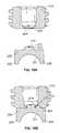
- the seat 327is formed of one or more inclined or slanted surfaces.
- the seat 327can be formed of an annular surface such that the seat 327 is generally conical or the seat 327 can be formed of three or more flat surfaces, such that the seat is pyramidal.
- the seat 327is conically shaped.
- the conically-shaped seat 327supports the rounded head 210 of the fixation element 110 .
- the head 210can be other shapes.
- the rounded head 210abuts against the conically-shaped seat 327 in the bottom of the coupling element 115 , as shown in the cross-sectional view of FIG. 20 b .
- the head portion 210contacts the conically-shaped seat 327 only along an annular contact region, which can be in the form of a contact circle 2010 as seen in FIGS. 20 b and 20 c . Because the seat 327 is conically shaped, the rounded head 210 can be rotated within the seat 327 to move the axis of the shank portion 205 to a desired orientation relative to the coupling element 115 and thereby provide a poly-axial configuration.
- an operatorcan position the assembly relative to a bone structure such as a vertebra.
- a drive devicesuch as an Allen wrench
- the operatorcan couple a drive device (such as an Allen wrench) to the drive cavity 215 in the head 210 and rotate the fixation element 110 to drive the shank portion 205 into a vertebra or other bone structure.
- the compression nut 410can be threaded downward.
- the downward force of the compression nut 410is transferred to the bottom saddle 320 via the top saddle 325 and the rod 120 .
- the rounded head 210is thereby wedged downward into the conically-shaped seat 327 in a fixed orientation.
- the force exerted by the rounded head 210 along the contact circle 2010can optionally cause an indentation, such as a slight indentation along contact circle 2010 . If present, the slight indentation along contact circle 2010 creates increased friction between the head 210 and the seat 327 which provides a secure fit between the rounded head 210 and the coupling element 115 .
- the position of the fixation element 110 relative to the coupling element 115is fixed. That is, the head 210 of the fixation element 110 is wedged downward into the conically-shaped seat 327 of the coupling element 115 with a force sufficient to lock the position of the head 210 relative to the coupling element 115 . This can occur whether or not the head forms an indentation in the seat.
- the compression nut 410provides a downward force that locks the relative positions of the elongated rod 120 , saddles 320 , 325 , coupling element 115 , and fixation element 110 .
- FIGS. 21 a , 21 b , and 21 cshow the seat 327 with a first conically shaped surface 2115 and a second conically shaped surface 2120 .
- the second conically shaped surface 2120has a pitch angle ⁇ from the horizontal that is greater than the pitch angle ⁇ of the first conically shaped surface.
- the rounded head 210abuts against the first conically shaped surface 2115 and the second conically shaped surface 2120 in the bottom of the coupling element 115 , as shown in the cross-sectional view of FIG. 21 b .
- the head portion 210contacts the conically-shaped seat 327 along a first contact region, such as a contact circle 2125 , and a second contact region, such as a circle 2130 , as seen in FIGS. 21 b and 21 c .
- the seat 327 in this embodimentallows the rounded head 210 to be rotated within the seat 327 so that the axis of the shank portion 205 can be moved to a desired orientation relative to the coupling element 115 and thereby provide a poly-axial configuration.
- the downward force of the compression nut 410is transferred to the head 210 of the fixation element 110 .
- the rounded head 210is thereby wedged downward into the seat 327 in a fixed orientation.
- the force exerted by the rounded head along the first contact circle 2125 and the second contact circle 2130can optionally cause an indentation, such as a slight indentation.
- the slight indentations along the first contact circle 2125 and the second contact circle 2130create a stronger friction fit between the rounded head 210 and the coupling element 115 . It should also be appreciated that there may be multiple conically shaped surfaces.
- the seat 327is pyramid shaped instead of conically-shaped.
- the pyramid-shaped seat in FIG. 22has three slanted faces 2240 , 2245 , 2250 . It should be appreciated that the pyramid-shaped seat 327 may have more than three faces.
- FIGS. 23 a and 23 bdepict the pyramid-shaped seat 327 with four faces 2340 , 2345 , 2350 , 2355 .
- the rounded head 210abuts against the pyramid-shaped seat 327 in the bottom of the coupling element 115 .
- the rounded head portion 210contacts the slanted faces of the three-sided pyramid-shaped seat at contact points 2251 as seen in FIG. 22 .
- the rounded head portion 210will contact the slanted faces of the three-sided pyramid-shaped seat at contact points 2360 .
- the rounded head 210can be rotated within the seat 327 to move the axis of the shank portion 205 to a desired orientation relative to the coupling element 115 and thereby provide a poly-axial configuration.
- the downward force of the compression nut 410is transferred to the head 210 of the fixation element 110 .
- the rounded head 210is thereby wedged downward into the pyramid shaped seat 327 in a fixed orientation.
- the force exerted by the rounded head at the contact pointscan cause a slight indentation.
- the slight indentations at the contact pointscreate a stronger friction fit between the rounded head 210 and the coupling element 115 .
- each of the slanted surface of the pyramidmay also have a variable pitch as seen in FIG. 24 .
- FIG. 24depicts each face having two variable pitches and each face having two contact points.
- the rounded headwould contact each face at two contact points 2410 .
- the downward force of the compression nut 410is transferred to the head 210 of the fixation element 110 .
- the rounded head 210is thereby wedged downward into the pyramid shaped seat 327 with variable-pitched faces in a fixed orientation.
- the force exerted by the rounded head at the contact pointscan cause a slight indentation.
- the slight indentations at the contact pointscreate a stronger friction fit.
- top saddlescompression nut threading geometries, and coupling element threading geometries are described herein with respect to polyaxial pedicle screws. However, it should be appreciated that they can be used with monoaxial pedicle screws as well.
Landscapes
- Health & Medical Sciences (AREA)
- Orthopedic Medicine & Surgery (AREA)
- Life Sciences & Earth Sciences (AREA)
- Neurology (AREA)
- Surgery (AREA)
- Heart & Thoracic Surgery (AREA)
- Engineering & Computer Science (AREA)
- Biomedical Technology (AREA)
- Nuclear Medicine, Radiotherapy & Molecular Imaging (AREA)
- Medical Informatics (AREA)
- Molecular Biology (AREA)
- Animal Behavior & Ethology (AREA)
- General Health & Medical Sciences (AREA)
- Public Health (AREA)
- Veterinary Medicine (AREA)
- Surgical Instruments (AREA)
Abstract
Description
Claims (6)
Priority Applications (3)
| Application Number | Priority Date | Filing Date | Title |
|---|---|---|---|
| US11/777,945US8137387B2 (en) | 2006-07-14 | 2007-07-13 | Pedicle screw assembly with inclined surface seat |
| US13/424,121US8480711B2 (en) | 2006-07-14 | 2012-03-19 | Pedicle screw assembly with inclined surface seat |
| US13/910,887US20130268006A1 (en) | 2006-07-14 | 2013-06-05 | Pedicle screw assembly with inclined surface seat |
Applications Claiming Priority (2)
| Application Number | Priority Date | Filing Date | Title |
|---|---|---|---|
| US83109406P | 2006-07-14 | 2006-07-14 | |
| US11/777,945US8137387B2 (en) | 2006-07-14 | 2007-07-13 | Pedicle screw assembly with inclined surface seat |
Related Child Applications (2)
| Application Number | Title | Priority Date | Filing Date |
|---|---|---|---|
| US13/424,121DivisionUS8480711B2 (en) | 2006-07-14 | 2012-03-19 | Pedicle screw assembly with inclined surface seat |
| US13/910,887DivisionUS20130268006A1 (en) | 2006-07-14 | 2013-06-05 | Pedicle screw assembly with inclined surface seat |
Publications (2)
| Publication Number | Publication Date |
|---|---|
| US20080045953A1 US20080045953A1 (en) | 2008-02-21 |
| US8137387B2true US8137387B2 (en) | 2012-03-20 |
Family
ID=38923944
Family Applications (3)
| Application Number | Title | Priority Date | Filing Date |
|---|---|---|---|
| US11/777,945Expired - Fee RelatedUS8137387B2 (en) | 2006-07-14 | 2007-07-13 | Pedicle screw assembly with inclined surface seat |
| US13/424,121Expired - Fee RelatedUS8480711B2 (en) | 2006-07-14 | 2012-03-19 | Pedicle screw assembly with inclined surface seat |
| US13/910,887AbandonedUS20130268006A1 (en) | 2006-07-14 | 2013-06-05 | Pedicle screw assembly with inclined surface seat |
Family Applications After (2)
| Application Number | Title | Priority Date | Filing Date |
|---|---|---|---|
| US13/424,121Expired - Fee RelatedUS8480711B2 (en) | 2006-07-14 | 2012-03-19 | Pedicle screw assembly with inclined surface seat |
| US13/910,887AbandonedUS20130268006A1 (en) | 2006-07-14 | 2013-06-05 | Pedicle screw assembly with inclined surface seat |
Country Status (2)
| Country | Link |
|---|---|
| US (3) | US8137387B2 (en) |
| WO (1) | WO2008008511A2 (en) |
Cited By (26)
| Publication number | Priority date | Publication date | Assignee | Title |
|---|---|---|---|---|
| US20100305621A1 (en)* | 2009-06-02 | 2010-12-02 | Alphatec Spine, Inc. | Bone screw assembly for limited angulation |
| US20110251650A1 (en)* | 2010-03-29 | 2011-10-13 | Lutz Biedermann | Bone anchoring device |
| US20130096622A1 (en)* | 2011-08-18 | 2013-04-18 | Timo Biedermann | Polyaxial bone anchoring device |
| US20130338717A1 (en)* | 2008-10-14 | 2013-12-19 | Us Spine, Inc. | Monoaxial and polyaxial pedicle screws and related methods |
| US8790374B2 (en) | 2004-04-08 | 2014-07-29 | Globus Medical, Inc. | Polyaxial screw |
| US8888827B2 (en) | 2011-07-15 | 2014-11-18 | Globus Medical, Inc. | Orthopedic fixation devices and methods of installation thereof |
| US8911479B2 (en) | 2012-01-10 | 2014-12-16 | Roger P. Jackson | Multi-start closures for open implants |
| US9034022B2 (en) | 2012-08-09 | 2015-05-19 | Spinecraft, LLC | Locking force augmentation features for surgical screw assembly |
| US9179957B2 (en) | 2012-08-09 | 2015-11-10 | Spinecraft, LLC | Systems, assemblies and methods for spinal derotation |
| US9186187B2 (en) | 2011-07-15 | 2015-11-17 | Globus Medical, Inc. | Orthopedic fixation devices and methods of installation thereof |
| US9192415B1 (en) | 2008-02-06 | 2015-11-24 | Nuvasive, Inc. | Systems and methods for holding and implanting bone anchors |
| US9198698B1 (en) | 2011-02-10 | 2015-12-01 | Nuvasive, Inc. | Minimally invasive spinal fixation system and related methods |
| US9198694B2 (en) | 2011-07-15 | 2015-12-01 | Globus Medical, Inc. | Orthopedic fixation devices and methods of installation thereof |
| US9259254B2 (en) | 2004-04-08 | 2016-02-16 | Globus Medical, Inc. | Polyaxial screw |
| US9358047B2 (en) | 2011-07-15 | 2016-06-07 | Globus Medical, Inc. | Orthopedic fixation devices and methods of installation thereof |
| US9974577B1 (en) | 2015-05-21 | 2018-05-22 | Nuvasive, Inc. | Methods and instruments for performing leveraged reduction during single position spine surgery |
| US9993269B2 (en) | 2011-07-15 | 2018-06-12 | Globus Medical, Inc. | Orthopedic fixation devices and methods of installation thereof |
| US10052136B2 (en) | 2015-03-12 | 2018-08-21 | Amedica Corporation | Spring cage spinal fixation systems |
| US10149702B2 (en) | 2015-01-12 | 2018-12-11 | Imds Llc | Polyaxial screw and rod system |
| US10188431B2 (en) | 2015-12-17 | 2019-01-29 | Deniz Ufuk Erbulut | Double-headed pedicle screw |
| US10265104B2 (en) | 2015-09-23 | 2019-04-23 | Deniz Ufuk Erbulut | Pedicle screw |
| US10398481B2 (en) | 2016-10-03 | 2019-09-03 | Nuvasive, Inc. | Spinal fixation system |
| US11051861B2 (en) | 2018-06-13 | 2021-07-06 | Nuvasive, Inc. | Rod reduction assemblies and related methods |
| US20230200858A1 (en)* | 2021-12-27 | 2023-06-29 | Aesculap Inc. | Favored Angle Pedicle Screw With One or More Oblique Bore Sections For Preventing Stress Concentrations |
| US20240032971A1 (en)* | 2009-02-20 | 2024-02-01 | Biedermann Technologies Gmbh & Co. Kg | Receiving part for receiving a rod for coupling the rod to a bone anchoring element and a bone anchoring device with such a receiving part |
| US11890034B1 (en)* | 2017-10-11 | 2024-02-06 | Seaspine Orthopedics Corporation | Collet for a polyaxial screw assembly |
Families Citing this family (99)
| Publication number | Priority date | Publication date | Assignee | Title |
|---|---|---|---|---|
| US7833250B2 (en) | 2004-11-10 | 2010-11-16 | Jackson Roger P | Polyaxial bone screw with helically wound capture connection |
| US8377100B2 (en) | 2000-12-08 | 2013-02-19 | Roger P. Jackson | Closure for open-headed medical implant |
| US11224464B2 (en) | 2002-05-09 | 2022-01-18 | Roger P. Jackson | Threaded closure with inwardly-facing tool engaging concave radiused structures and axial through-aperture |
| US8876868B2 (en) | 2002-09-06 | 2014-11-04 | Roger P. Jackson | Helical guide and advancement flange with radially loaded lip |
| US7377923B2 (en) | 2003-05-22 | 2008-05-27 | Alphatec Spine, Inc. | Variable angle spinal screw assembly |
| US8366753B2 (en) | 2003-06-18 | 2013-02-05 | Jackson Roger P | Polyaxial bone screw assembly with fixed retaining structure |
| US7967850B2 (en) | 2003-06-18 | 2011-06-28 | Jackson Roger P | Polyaxial bone anchor with helical capture connection, insert and dual locking assembly |
| US8926670B2 (en) | 2003-06-18 | 2015-01-06 | Roger P. Jackson | Polyaxial bone screw assembly |
| US7776067B2 (en) | 2005-05-27 | 2010-08-17 | Jackson Roger P | Polyaxial bone screw with shank articulation pressure insert and method |
| US7766915B2 (en) | 2004-02-27 | 2010-08-03 | Jackson Roger P | Dynamic fixation assemblies with inner core and outer coil-like member |
| US8951290B2 (en) | 2004-08-27 | 2015-02-10 | Blackstone Medical, Inc. | Multi-axial connection system |
| US20060058788A1 (en)* | 2004-08-27 | 2006-03-16 | Hammer Michael A | Multi-axial connection system |
| WO2006047711A2 (en) | 2004-10-25 | 2006-05-04 | Alphaspine, Inc. | Pedicle screw systems and methods |
| US7604655B2 (en) | 2004-10-25 | 2009-10-20 | X-Spine Systems, Inc. | Bone fixation system and method for using the same |
| US8926672B2 (en) | 2004-11-10 | 2015-01-06 | Roger P. Jackson | Splay control closure for open bone anchor |
| US8444681B2 (en) | 2009-06-15 | 2013-05-21 | Roger P. Jackson | Polyaxial bone anchor with pop-on shank, friction fit retainer and winged insert |
| US9168069B2 (en) | 2009-06-15 | 2015-10-27 | Roger P. Jackson | Polyaxial bone anchor with pop-on shank and winged insert with lower skirt for engaging a friction fit retainer |
| US9980753B2 (en) | 2009-06-15 | 2018-05-29 | Roger P Jackson | pivotal anchor with snap-in-place insert having rotation blocking extensions |
| US7901437B2 (en) | 2007-01-26 | 2011-03-08 | Jackson Roger P | Dynamic stabilization member with molded connection |
| US7717943B2 (en) | 2005-07-29 | 2010-05-18 | X-Spine Systems, Inc. | Capless multiaxial screw and spinal fixation assembly and method |
| WO2007041702A2 (en) | 2005-10-04 | 2007-04-12 | Alphaspine, Inc. | Pedicle screw system with provisional locking aspects |
| US8097025B2 (en) | 2005-10-25 | 2012-01-17 | X-Spine Systems, Inc. | Pedicle screw system configured to receive a straight or curved rod |
| WO2008039790A1 (en)* | 2006-09-25 | 2008-04-03 | Zimmer Spine, Inc. | Apparatus for connecting a longitudinal member to a bone portion |
| WO2008118295A2 (en)* | 2007-03-26 | 2008-10-02 | Laszlo Garamszegi | Bottom-loading pedicle screw assembly |
| US8979904B2 (en) | 2007-05-01 | 2015-03-17 | Roger P Jackson | Connecting member with tensioned cord, low profile rigid sleeve and spacer with torsion control |
| US7942910B2 (en) | 2007-05-16 | 2011-05-17 | Ortho Innovations, Llc | Polyaxial bone screw |
| US7951173B2 (en)* | 2007-05-16 | 2011-05-31 | Ortho Innovations, Llc | Pedicle screw implant system |
| US7942911B2 (en) | 2007-05-16 | 2011-05-17 | Ortho Innovations, Llc | Polyaxial bone screw |
| US7942909B2 (en) | 2009-08-13 | 2011-05-17 | Ortho Innovations, Llc | Thread-thru polyaxial pedicle screw system |
| US7947065B2 (en) | 2008-11-14 | 2011-05-24 | Ortho Innovations, Llc | Locking polyaxial ball and socket fastener |
| US8197518B2 (en) | 2007-05-16 | 2012-06-12 | Ortho Innovations, Llc | Thread-thru polyaxial pedicle screw system |
| US8007522B2 (en) | 2008-02-04 | 2011-08-30 | Depuy Spine, Inc. | Methods for correction of spinal deformities |
| US20090228046A1 (en)* | 2008-03-04 | 2009-09-10 | Laszlo Garamszegi | Transverse vertebral connector |
| AU2010260521C1 (en)* | 2008-08-01 | 2013-08-01 | Roger P. Jackson | Longitudinal connecting member with sleeved tensioned cords |
| US8075603B2 (en) | 2008-11-14 | 2011-12-13 | Ortho Innovations, Llc | Locking polyaxial ball and socket fastener |
| US9668771B2 (en) | 2009-06-15 | 2017-06-06 | Roger P Jackson | Soft stabilization assemblies with off-set connector |
| US11464549B2 (en) | 2009-06-15 | 2022-10-11 | Roger P. Jackson | Pivotal bone anchor assembly with horizontal tool engagement grooves and insert with upright arms having flared outer portions |
| CN103826560A (en) | 2009-06-15 | 2014-05-28 | 罗杰.P.杰克逊 | Polyaxial Bone Anchor with Socket Stem and Winged Inserts with Friction Fit Compression Collars |
| US11229457B2 (en) | 2009-06-15 | 2022-01-25 | Roger P. Jackson | Pivotal bone anchor assembly with insert tool deployment |
| US8998959B2 (en) | 2009-06-15 | 2015-04-07 | Roger P Jackson | Polyaxial bone anchors with pop-on shank, fully constrained friction fit retainer and lock and release insert |
| US8236035B1 (en) | 2009-06-16 | 2012-08-07 | Bedor Bernard M | Spinal fixation system and method |
| US8876867B2 (en)* | 2009-06-24 | 2014-11-04 | Zimmer Spine, Inc. | Spinal correction tensioning system |
| EP2286748B1 (en)* | 2009-08-20 | 2014-05-28 | Biedermann Technologies GmbH & Co. KG | Bone anchoring device |
| US20110066187A1 (en)* | 2009-09-11 | 2011-03-17 | Zimmer Spine, Inc. | Spinal stabilization system |
| EP2485654B1 (en) | 2009-10-05 | 2021-05-05 | Jackson P. Roger | Polyaxial bone anchor with non-pivotable retainer and pop-on shank, some with friction fit |
| WO2011063410A1 (en) | 2009-11-23 | 2011-05-26 | Felix Quevedo | Cam lock pedicle screw |
| ES2525046T3 (en)* | 2009-12-21 | 2014-12-16 | Biedermann Technologies Gmbh & Co. Kg | Bone anchoring device |
| WO2011106339A1 (en)* | 2010-02-23 | 2011-09-01 | K2M, Inc. | Polyaxial bone screw assembly |
| WO2012030712A1 (en) | 2010-08-30 | 2012-03-08 | Zimmer Spine, Inc. | Polyaxial pedicle screw |
| EP2637584A4 (en)* | 2010-10-15 | 2015-01-28 | Alphatec Holdings Inc | FIXING SCREW ASSEMBLY |
| AU2011324058A1 (en) | 2010-11-02 | 2013-06-20 | Roger P. Jackson | Polyaxial bone anchor with pop-on shank and pivotable retainer |
| EP3047812B1 (en)* | 2010-11-22 | 2020-01-01 | Biedermann Technologies GmbH & Co. KG | Polyaxial bone anchoring device |
| US9044274B2 (en) | 2010-12-01 | 2015-06-02 | Amendia, Inc. | Bone screw system |
| EP2659845A1 (en) | 2010-12-27 | 2013-11-06 | Biedermann Technologies GmbH & Co. KG | Polyaxial bone anchoring device |
| EP2502594B1 (en)* | 2011-03-22 | 2014-12-03 | Medacta International S.A. | Polyaxial pedicle screw and fixation system kit comprising said screw |
| JP5865479B2 (en) | 2011-03-24 | 2016-02-17 | ロジャー・ピー・ジャクソン | Multiaxial bone anchor with compound joint and pop-mounted shank |
| US9072551B2 (en)* | 2011-06-09 | 2015-07-07 | Christel Paroth | Surgical instrument |
| DE102011050996A1 (en)* | 2011-06-09 | 2012-12-13 | Zbigniew Combrowski | Surgical instrument |
| US8906068B1 (en)* | 2011-09-13 | 2014-12-09 | Bernard M. Bedor | Spinal fixation system and method |
| EP2606841B1 (en)* | 2011-12-23 | 2016-03-09 | Biedermann Technologies GmbH & Co. KG | Polyaxial bone anchoring device |
| US9427260B2 (en)* | 2012-03-01 | 2016-08-30 | Globus Medical, Inc. | Closed-head polyaxial and monaxial screws |
| US9271759B2 (en)* | 2012-03-09 | 2016-03-01 | Institute Of Musculoskeletal Science And Education, Ltd. | Pedicle screw assembly with locking cap |
| EP2674123B1 (en) | 2012-06-11 | 2018-03-21 | Biedermann Technologies GmbH & Co. KG | Polyaxial bone anchoring device |
| EP2687171B1 (en) | 2012-07-18 | 2015-04-22 | Biedermann Technologies GmbH & Co. KG | Polyaxial bone anchoring device |
| KR101389407B1 (en)* | 2012-08-27 | 2014-05-27 | 한림대학교 산학협력단 | Implant for spine fixation |
| US9782204B2 (en) | 2012-09-28 | 2017-10-10 | Medos International Sarl | Bone anchor assemblies |
| US8911478B2 (en) | 2012-11-21 | 2014-12-16 | Roger P. Jackson | Splay control closure for open bone anchor |
| US10058354B2 (en) | 2013-01-28 | 2018-08-28 | Roger P. Jackson | Pivotal bone anchor assembly with frictional shank head seating surfaces |
| EP2764840B1 (en)* | 2013-02-11 | 2017-05-03 | Biedermann Technologies GmbH & Co. KG | Coupling assembly for coupling a rod to a bone anchoring element and bone anchoring device with such a coupling assembly |
| US8852239B2 (en) | 2013-02-15 | 2014-10-07 | Roger P Jackson | Sagittal angle screw with integral shank and receiver |
| US10342582B2 (en) | 2013-03-14 | 2019-07-09 | DePuy Synthes Products, Inc. | Bone anchor assemblies and methods with improved locking |
| US9724145B2 (en) | 2013-03-14 | 2017-08-08 | Medos International Sarl | Bone anchor assemblies with multiple component bottom loading bone anchors |
| US9775660B2 (en) | 2013-03-14 | 2017-10-03 | DePuy Synthes Products, Inc. | Bottom-loading bone anchor assemblies and methods |
| US20140277153A1 (en) | 2013-03-14 | 2014-09-18 | DePuy Synthes Products, LLC | Bone Anchor Assemblies and Methods With Improved Locking |
| US9259247B2 (en) | 2013-03-14 | 2016-02-16 | Medos International Sarl | Locking compression members for use with bone anchor assemblies and methods |
| US9486256B1 (en) | 2013-03-15 | 2016-11-08 | Nuvasive, Inc. | Rod reduction assemblies and related methods |
| US9453526B2 (en) | 2013-04-30 | 2016-09-27 | Degen Medical, Inc. | Bottom-loading anchor assembly |
| US20150012042A1 (en)* | 2013-07-04 | 2015-01-08 | Institute for Musculoskeletal Science and Education, Ltd. | Orthopedic implantation device |
| EP2826429B1 (en)* | 2013-07-19 | 2016-09-14 | Biedermann Technologies GmbH & Co. KG | Polyaxial bone anchoring device |
| DE102013110796A1 (en) | 2013-09-30 | 2015-04-02 | Z-Medical Gmbh & Co. Kg | Surgical instrument |
| US9566092B2 (en) | 2013-10-29 | 2017-02-14 | Roger P. Jackson | Cervical bone anchor with collet retainer and outer locking sleeve |
| KR101524941B1 (en)* | 2013-11-08 | 2015-06-01 | (주)시지바이오 | Implant for spine fixation |
| KR101553705B1 (en) | 2013-12-06 | 2015-09-17 | (주)시지바이오 | Implant for spine fixation |
| US9717533B2 (en) | 2013-12-12 | 2017-08-01 | Roger P. Jackson | Bone anchor closure pivot-splay control flange form guide and advancement structure |
| US9451993B2 (en) | 2014-01-09 | 2016-09-27 | Roger P. Jackson | Bi-radial pop-on cervical bone anchor |
| US10463400B2 (en) | 2014-02-28 | 2019-11-05 | The General Hospital Corporation | Bone surgical apparatus with ratcheting function |
| US9597119B2 (en) | 2014-06-04 | 2017-03-21 | Roger P. Jackson | Polyaxial bone anchor with polymer sleeve |
| US10064658B2 (en) | 2014-06-04 | 2018-09-04 | Roger P. Jackson | Polyaxial bone anchor with insert guides |
| EP2977017A1 (en) | 2014-07-22 | 2016-01-27 | LfC sp. z o.o. | Pedicle anchor assembly |
| EP3031415B1 (en) | 2014-12-10 | 2018-10-31 | Biedermann Technologies GmbH & Co. KG | Coupling assembly and polyaxial bone anchoring device comprising the same |
| CN104783886B (en)* | 2015-05-06 | 2017-09-19 | 山东威高骨科材料股份有限公司 | Undercut mark screw base and the assembly method for positioning pressure ring |
| DE102015109481A1 (en)* | 2015-06-15 | 2016-12-15 | Aesculap Ag | Pedicle screw with radially offset guide |
| JP6643364B2 (en) | 2015-06-25 | 2020-02-12 | インスティテュート フォー マスキュロスケレタル サイエンス アンド エジュケイション,リミテッド | Interbody fusion device and system for implantation |
| US9968378B1 (en)* | 2015-07-22 | 2018-05-15 | University Of South Florida | Adaptation sphere saddle |
| US10307265B2 (en) | 2016-10-18 | 2019-06-04 | Institute for Musculoskeletal Science and Education, Ltd. | Implant with deployable blades |
| US10405992B2 (en) | 2016-10-25 | 2019-09-10 | Institute for Musculoskeletal Science and Education, Ltd. | Spinal fusion implant |
| WO2020102787A1 (en) | 2018-11-16 | 2020-05-22 | Surber, James L. | Pivotal bone anchor assembly having a deployable collet insert with internal pressure ring |
| IL302256A (en)* | 2020-10-23 | 2023-06-01 | Carbofix Spine Inc | The devices are made of a composite material for connecting an orthopedic rod to a pedicle screw and complementary tools |
| WO2022184797A1 (en) | 2021-03-05 | 2022-09-09 | Medos International Sarl | Selectively locking polyaxial screw |
Citations (130)
| Publication number | Priority date | Publication date | Assignee | Title |
|---|---|---|---|---|
| US4805602A (en) | 1986-11-03 | 1989-02-21 | Danninger Medical Technology | Transpedicular screw and rod system |
| US4887596A (en) | 1988-03-02 | 1989-12-19 | Synthes (U.S.A.) | Open backed pedicle screw |
| US4946458A (en) | 1986-04-25 | 1990-08-07 | Harms Juergen | Pedicle screw |
| US4950269A (en) | 1988-06-13 | 1990-08-21 | Acromed Corporation | Spinal column fixation device |
| US5042982A (en) | 1987-07-08 | 1991-08-27 | Harms Juergen | Positioning device |
| US5084048A (en) | 1989-07-12 | 1992-01-28 | Sulzer Brothers Limited | Implant for vertebrae with spinal stabilizer |
| US5092867A (en) | 1988-07-13 | 1992-03-03 | Harms Juergen | Correction and supporting apparatus, in particular for the spinal column |
| US5129388A (en) | 1989-02-09 | 1992-07-14 | Vignaud Jean Louis | Device for supporting the spinal column |
| US5190543A (en) | 1990-11-26 | 1993-03-02 | Synthes (U.S.A.) | Anchoring device |
| US5196013A (en) | 1989-11-03 | 1993-03-23 | Harms Juergen | Pedicel screw and correcting and supporting apparatus comprising such screw |
| US5207678A (en) | 1989-07-20 | 1993-05-04 | Prufer | Pedicle screw and receiver member therefore |
| US5217497A (en) | 1990-07-04 | 1993-06-08 | Mehdian Seyed M H | Apparatus for use in the treatment of spinal disorders |
| US5254118A (en) | 1991-12-04 | 1993-10-19 | Srdjian Mirkovic | Three dimensional spine fixation system |
| US5261912A (en) | 1990-08-21 | 1993-11-16 | Synthes (U.S.A.) | Implant for an osteosynthesis device, in particular for spinal column correction |
| EP0608623A1 (en) | 1992-12-28 | 1994-08-03 | Advance Spine Fixation Systems, Inc. | Cervical spine rod fixation system |
| US5360431A (en) | 1990-04-26 | 1994-11-01 | Cross Medical Products | Transpedicular screw system and method of use |
| US5437671A (en) | 1992-03-10 | 1995-08-01 | Zimmer, Inc. | Perpendicular rod connector for spinal fixation device |
| US5443467A (en) | 1993-03-10 | 1995-08-22 | Biedermann Motech Gmbh | Bone screw |
| US5466237A (en) | 1993-11-19 | 1995-11-14 | Cross Medical Products, Inc. | Variable locking stabilizer anchor seat and screw |
| US5476464A (en) | 1993-02-25 | 1995-12-19 | Howmedica Gmbh | Device for setting a spine |
| US5496321A (en) | 1993-11-19 | 1996-03-05 | Cross Medical Products, Inc. | Rod anchor seat having a sliding interlocking rod connector |
| US5520689A (en) | 1992-06-04 | 1996-05-28 | Synthes (U.S.A.) | Osteosynthetic fastening device |
| US5520690A (en) | 1995-04-13 | 1996-05-28 | Errico; Joseph P. | Anterior spinal polyaxial locking screw plate assembly |
| US5534001A (en) | 1993-05-11 | 1996-07-09 | Synthes (U.S.A.) | Osteosynthetic fixation element and manipulation device |
| US5545165A (en) | 1992-10-09 | 1996-08-13 | Biedermann Motech Gmbh | Anchoring member |
| US5545166A (en) | 1994-07-14 | 1996-08-13 | Advanced Spine Fixation Systems, Incorporated | Spinal segmental reduction derotational fixation system |
| US5549608A (en) | 1995-07-13 | 1996-08-27 | Fastenetix, L.L.C. | Advanced polyaxial locking screw and coupling element device for use with rod fixation apparatus |
| US5554157A (en) | 1995-07-13 | 1996-09-10 | Fastenetix, L.L.C. | Rod securing polyaxial locking screw and coupling element assembly |
| US5562688A (en) | 1994-03-25 | 1996-10-08 | Riza; Erol D. | Apparatus facilitating suturing in laparoscopic surgery |
| US5562661A (en) | 1995-03-16 | 1996-10-08 | Alphatec Manufacturing Incorporated | Top tightening bone fixation apparatus |
| US5586984A (en) | 1995-07-13 | 1996-12-24 | Fastenetix, L.L.C. | Polyaxial locking screw and coupling element assembly for use with rod fixation apparatus |
| EP0582857B1 (en) | 1992-08-12 | 1997-02-05 | Synthes AG, Chur | Spinal fixation element |
| FR2622430B1 (en) | 1987-10-30 | 1997-04-25 | Laboureau Jacques | SURGICAL CLIP FOR THE IMMEDIATE FIXATION OF ARTIFICIAL LIGAMENTS AND ANCILLARY INSTRUMENT FOR ITS IMPLANTATION INTO THE BONE |
| US5628740A (en) | 1993-12-23 | 1997-05-13 | Mullane; Thomas S. | Articulating toggle bolt bone screw |
| DE19542116A1 (en) | 1995-11-11 | 1997-05-15 | Peter Brehm | Device for fixing implant to bone |
| US5669911A (en) | 1995-04-13 | 1997-09-23 | Fastenetix, L.L.C. | Polyaxial pedicle screw |
| US5672176A (en) | 1995-03-15 | 1997-09-30 | Biedermann; Lutz | Anchoring member |
| US5683390A (en) | 1994-02-22 | 1997-11-04 | Howmedica Gmbh | Correcting a spinal column |
| US5697929A (en) | 1995-10-18 | 1997-12-16 | Cross Medical Products, Inc. | Self-limiting set screw for use with spinal implant systems |
| US5716356A (en) | 1994-07-18 | 1998-02-10 | Biedermann; Lutz | Anchoring member and adjustment tool therefor |
| US5728098A (en) | 1996-11-07 | 1998-03-17 | Sdgi Holdings, Inc. | Multi-angle bone screw assembly using shape-memory technology |
| US5733286A (en) | 1997-02-12 | 1998-03-31 | Third Millennium Engineering, Llc | Rod securing polyaxial locking screw and coupling element assembly |
| US5733285A (en) | 1995-07-13 | 1998-03-31 | Fastenetix, Llc | Polyaxial locking mechanism |
| US5752957A (en) | 1997-02-12 | 1998-05-19 | Third Millennium Engineering, Llc | Polyaxial mechanism for use with orthopaedic implant devices |
| US5782833A (en) | 1996-12-20 | 1998-07-21 | Haider; Thomas T. | Pedicle screw system for osteosynthesis |
| US5797911A (en) | 1996-09-24 | 1998-08-25 | Sdgi Holdings, Inc. | Multi-axial bone screw assembly |
| US5863293A (en) | 1996-10-18 | 1999-01-26 | Spinal Innovations | Spinal implant fixation assembly |
| US5873878A (en) | 1996-04-30 | 1999-02-23 | Harms; Juergen | Anchoring member |
| US5879350A (en) | 1996-09-24 | 1999-03-09 | Sdgi Holdings, Inc. | Multi-axial bone screw assembly |
| US5885286A (en) | 1996-09-24 | 1999-03-23 | Sdgi Holdings, Inc. | Multi-axial bone screw assembly |
| US5891145A (en) | 1997-07-14 | 1999-04-06 | Sdgi Holdings, Inc. | Multi-axial screw |
| US5961517A (en) | 1994-07-18 | 1999-10-05 | Biedermann; Lutz | Anchoring member and adjustment tool therefor |
| US5964760A (en) | 1996-10-18 | 1999-10-12 | Spinal Innovations | Spinal implant fixation assembly |
| US5980521A (en) | 1995-03-30 | 1999-11-09 | Sdgi Holdings,Inc. | Top-tightening transverse connector for a spinal fixation system |
| US5989254A (en) | 1997-05-20 | 1999-11-23 | Katz; Akiva Raphael | Pedicle screw assembly |
| US6001098A (en) | 1997-01-17 | 1999-12-14 | Howmedica Gmbh | Connecting element for spinal stabilizing system |
| US6015409A (en) | 1994-05-25 | 2000-01-18 | Sdgi Holdings, Inc. | Apparatus and method for spinal fixation and correction of spinal deformities |
| US6022350A (en) | 1996-05-13 | 2000-02-08 | Stryker France S.A. | Bone fixing device, in particular for fixing to the sacrum during osteosynthesis of the backbone |
| US6050997A (en) | 1999-01-25 | 2000-04-18 | Mullane; Thomas S. | Spinal fixation system |
| US6063090A (en) | 1996-12-12 | 2000-05-16 | Synthes (U.S.A.) | Device for connecting a longitudinal support to a pedicle screw |
| US6074391A (en) | 1997-06-16 | 2000-06-13 | Howmedica Gmbh | Receiving part for a retaining component of a vertebral column implant |
| US6077262A (en) | 1993-06-04 | 2000-06-20 | Synthes (U.S.A.) | Posterior spinal implant |
| US6090111A (en) | 1998-06-17 | 2000-07-18 | Surgical Dynamics, Inc. | Device for securing spinal rods |
| US6090110A (en) | 1992-03-02 | 2000-07-18 | Howmedica Gmbh | Apparatus for bracing vertebrae |
| US6106526A (en) | 1995-03-15 | 2000-08-22 | Harms; Juergen | Member for stabilizing cervical vertebrae |
| US6113601A (en) | 1998-06-12 | 2000-09-05 | Bones Consulting, Llc | Polyaxial pedicle screw having a loosely coupled locking cap |
| US6179841B1 (en) | 1997-01-06 | 2001-01-30 | Medtronic Sofamor Danek, Incorporated | Set screw for use with osteosynthesis apparatus |
| US6183472B1 (en) | 1998-04-09 | 2001-02-06 | Howmedica Gmbh | Pedicle screw and an assembly aid therefor |
| US6248105B1 (en) | 1997-05-17 | 2001-06-19 | Synthes (U.S.A.) | Device for connecting a longitudinal support with a pedicle screw |
| US6280442B1 (en) | 1999-09-01 | 2001-08-28 | Sdgi Holdings, Inc. | Multi-axial bone screw assembly |
| US6296642B1 (en) | 1998-11-09 | 2001-10-02 | Sdgi Holdings, Inc. | Reverse angle thread for preventing splaying in medical devices |
| US20010056283A1 (en) | 1993-08-25 | 2001-12-27 | James E. Carter | Devices for investing within ligaments for retracting and reinforcing the same |
| US6371957B1 (en) | 1997-01-22 | 2002-04-16 | Synthes (Usa) | Device for connecting a longitudinal bar to a pedicle screw |
| US20020082601A1 (en) | 2000-12-27 | 2002-06-27 | Yoshiaki Toyama | Vertebra correcting and fixing device |
| US20020106260A1 (en) | 2001-01-26 | 2002-08-08 | Manfred Schenk | Screw connection with countersunk screw |
| US6440133B1 (en) | 2001-07-03 | 2002-08-27 | Sdgi Holdings, Inc. | Rod reducer instruments and methods |
| US20020120272A1 (en) | 1998-06-17 | 2002-08-29 | Hansen Yuan | Device for securing spinal rods |
| US6443953B1 (en) | 2000-02-08 | 2002-09-03 | Cross Medical Products, Inc. | Self-aligning cap nut for use with a spinal rod anchor |
| US20020143341A1 (en) | 2001-03-27 | 2002-10-03 | Lutz Biedermann | Anchoring element |
| US6471705B1 (en) | 1999-08-02 | 2002-10-29 | Lutz Biedermann | Bone screw |
| US20020169450A1 (en) | 2001-04-24 | 2002-11-14 | Co-Ligne Ag | Instrumentation for stabilizing certain vertebrae of the spine |
| US6485491B1 (en) | 2000-09-15 | 2002-11-26 | Sdgi Holdings, Inc. | Posterior fixation system |
| US6488681B2 (en) | 2001-01-05 | 2002-12-03 | Stryker Spine S.A. | Pedicle screw assembly |
| FR2802796B1 (en) | 1999-12-24 | 2002-12-27 | Materiel Orthopedique En Abreg | INSTRUMENTATION FOR SHRINKAGE OF THE RACHIS COMPRISING SCREWS WITH INCLINED HEADS |
| US20030055426A1 (en) | 2001-09-14 | 2003-03-20 | John Carbone | Biased angulation bone fixation assembly |
| US6554834B1 (en) | 1999-10-07 | 2003-04-29 | Stryker Spine | Slotted head pedicle screw assembly |
| US20030088248A1 (en) | 2001-11-07 | 2003-05-08 | Reed Gary Jack | Orthopedic stabilization device and method |
| US20030100904A1 (en) | 2001-11-27 | 2003-05-29 | Lutz Biedermann | Locking device for securing a rod-shaped element in a holding element connected to a shank |
| US6582436B2 (en) | 1998-09-29 | 2003-06-24 | Synthes (U.S.A.) | Device for connecting a longitudinal support to a bone anchor |
| US6585737B1 (en) | 1998-04-30 | 2003-07-01 | Stryker Spine | Backbone osteosynthesis system with collar and lock |
| US20030153911A1 (en) | 2002-02-13 | 2003-08-14 | Endius Incorporated | Apparatus for connecting a longitudinal member to a bone portion |
| US6610063B2 (en) | 2000-07-28 | 2003-08-26 | Synthes (Usa) | Spinal fixation system |
| US20030167058A1 (en) | 2002-03-01 | 2003-09-04 | Endius Incorporated | Apparatus for connecting a longitudinal member to a bone portion |
| US6641586B2 (en) | 2002-02-01 | 2003-11-04 | Depuy Acromed, Inc. | Closure system for spinal fixation instrumentation |
| US6660006B2 (en) | 2002-04-17 | 2003-12-09 | Stryker Spine | Rod persuader |
| US6663635B2 (en) | 1999-07-07 | 2003-12-16 | Synthes (U.S.A.) | Bone screw with two-part screw head |
| DE10233164A1 (en) | 2002-07-22 | 2004-02-05 | Mtm Medizintechnik Mauk Gmbh | Joint for use in medical equipment comprises ball attached to one component and socket formed in other, surface of ball being deformable along line joining its points of contact with socket walls |
| US6695843B2 (en) | 2000-12-22 | 2004-02-24 | Biedermann Motech Gmbh | Fixing element |
| US6723100B2 (en) | 2001-07-27 | 2004-04-20 | Biedermann Motech Gmbh | Bone screw and fastening tool for same |
| US20040087978A1 (en) | 2002-08-27 | 2004-05-06 | Velez Juan Manuel | Surgical fascia closure instrument, guide and method |
| US6736820B2 (en) | 2000-11-10 | 2004-05-18 | Biedermann Motech Gmbh | Bone screw |
| US6755829B1 (en) | 2000-09-22 | 2004-06-29 | Depuy Acromed, Inc. | Lock cap anchor assembly for orthopaedic fixation |
| US6770075B2 (en) | 2001-05-17 | 2004-08-03 | Robert S. Howland | Spinal fixation apparatus with enhanced axial support and methods for use |
| US6783527B2 (en) | 2001-10-30 | 2004-08-31 | Sdgi Holdings, Inc. | Flexible spinal stabilization system and method |
| US20040181224A1 (en) | 2003-03-11 | 2004-09-16 | Biedermann Motech Gmbh | Anchoring element for use in spine or bone surgery, methods for use and production thereof |
| US20040186473A1 (en) | 2003-03-21 | 2004-09-23 | Cournoyer John R. | Spinal fixation devices of improved strength and rigidity |
| US6802844B2 (en) | 2001-03-26 | 2004-10-12 | Nuvasive, Inc | Spinal alignment apparatus and methods |
| US20040260283A1 (en) | 2003-06-19 | 2004-12-23 | Shing-Cheng Wu | Multi-axis spinal fixation device |
| US6843791B2 (en) | 2003-01-10 | 2005-01-18 | Depuy Acromed, Inc. | Locking cap assembly for spinal fixation instrumentation |
| US20050033436A1 (en) | 2001-12-31 | 2005-02-10 | Synthes U.S.A. | Device for a ball-and-socket joint type connection of two members |
| US6869433B2 (en) | 2001-01-12 | 2005-03-22 | Depuy Acromed, Inc. | Polyaxial screw with improved locking |
| US20050070901A1 (en) | 2003-09-26 | 2005-03-31 | Stryker Spine | Bone fixation assembly and method |
| US20050080419A1 (en) | 2002-02-11 | 2005-04-14 | Synthes U.S.A. | Device for connecting a longitudinal member to a bone |
| US6905500B2 (en) | 2001-10-31 | 2005-06-14 | U & I Corporation | Bone fixation apparatus |
| US20050154391A1 (en) | 2003-12-30 | 2005-07-14 | Thomas Doherty | Bone anchor assemblies |
| US6945975B2 (en)* | 2003-07-07 | 2005-09-20 | Aesculap, Inc. | Bone fixation assembly and method of securement |
| US20050228385A1 (en) | 2004-04-08 | 2005-10-13 | Globus Medical Inc. | Polyaxial screw |
| US20050240180A1 (en) | 2001-09-03 | 2005-10-27 | Cecile Vienney | Spinal osteosynthesis system comprising a support pad |
| US20050261687A1 (en) | 2004-04-20 | 2005-11-24 | Laszlo Garamszegi | Pedicle screw assembly |
| US20050283157A1 (en) | 2004-06-17 | 2005-12-22 | Coates Bradley J | Multi-axial bone attachment assembly |
| US7018378B2 (en) | 2000-12-27 | 2006-03-28 | Biedermann Motech Gmbh | Screw |
| US7063701B2 (en) | 1999-05-05 | 2006-06-20 | Sdgi Holdings, Inc. | Screws of cortical bone having a trailing end configured to cooperatively engage an implant |
| DE102005021879A1 (en)* | 2005-05-04 | 2006-11-30 | Aesculap Ag & Co. Kg | Orthopedic anchoring unit e.g. pedicle screw, for ostheosynthesis device, has screw with outer thread corresponding to internal thread of slot, where pitch of outer thread is partially distant based on thread end flowing into screw end |
| US20070043357A1 (en)* | 2005-07-29 | 2007-02-22 | X-Spine Systems, Inc. | Capless multiaxial screw and spinal fixation assembly and method |
| US7211086B2 (en) | 2001-12-28 | 2007-05-01 | Biedermann Motech Gmbh | Locking device for securing a rod-shaped element in a holding element connected to a shank |
| US20070270813A1 (en) | 2006-04-12 | 2007-11-22 | Laszlo Garamszegi | Pedicle screw assembly |
| US20070282337A1 (en) | 2006-05-18 | 2007-12-06 | Laszlo Garamszegi | Rod reducer |
| US7311712B2 (en)* | 2004-02-26 | 2007-12-25 | Aesculap Implant Systems, Inc. | Polyaxial locking screw plate assembly |
| US20090163956A1 (en)* | 2007-12-13 | 2009-06-25 | Lutz Biedermann | Anchoring device for anchoring a rod in bones or vertebrae |
| US7699876B2 (en)* | 2006-11-08 | 2010-04-20 | Ebi, Llc | Multi-axial bone fixation apparatus |
Family Cites Families (4)
| Publication number | Priority date | Publication date | Assignee | Title |
|---|---|---|---|---|
| US3288501A (en)* | 1962-10-22 | 1966-11-29 | J J Tourek Mfg Co | Ball joint |
| FR2822053B1 (en)* | 2001-03-15 | 2003-06-20 | Stryker Spine Sa | ANCHORING MEMBER WITH SAFETY RING FOR SPINAL OSTEOSYNTHESIS SYSTEM |
| DE60238997D1 (en)* | 2001-09-28 | 2011-03-03 | Stephen Ritland | CHROME OR HOOKS |
| US7766945B2 (en) | 2004-08-10 | 2010-08-03 | Lanx, Inc. | Screw and rod fixation system |
- 2007
- 2007-07-12WOPCT/US2007/016028patent/WO2008008511A2/enactiveApplication Filing
- 2007-07-13USUS11/777,945patent/US8137387B2/ennot_activeExpired - Fee Related
- 2012
- 2012-03-19USUS13/424,121patent/US8480711B2/ennot_activeExpired - Fee Related
- 2013
- 2013-06-05USUS13/910,887patent/US20130268006A1/ennot_activeAbandoned
Patent Citations (165)
| Publication number | Priority date | Publication date | Assignee | Title |
|---|---|---|---|---|
| US4946458A (en) | 1986-04-25 | 1990-08-07 | Harms Juergen | Pedicle screw |
| US4805602A (en) | 1986-11-03 | 1989-02-21 | Danninger Medical Technology | Transpedicular screw and rod system |
| US5042982A (en) | 1987-07-08 | 1991-08-27 | Harms Juergen | Positioning device |
| FR2622430B1 (en) | 1987-10-30 | 1997-04-25 | Laboureau Jacques | SURGICAL CLIP FOR THE IMMEDIATE FIXATION OF ARTIFICIAL LIGAMENTS AND ANCILLARY INSTRUMENT FOR ITS IMPLANTATION INTO THE BONE |
| US4887596A (en) | 1988-03-02 | 1989-12-19 | Synthes (U.S.A.) | Open backed pedicle screw |
| US4950269A (en) | 1988-06-13 | 1990-08-21 | Acromed Corporation | Spinal column fixation device |
| US5092867A (en) | 1988-07-13 | 1992-03-03 | Harms Juergen | Correction and supporting apparatus, in particular for the spinal column |
| US5129388A (en) | 1989-02-09 | 1992-07-14 | Vignaud Jean Louis | Device for supporting the spinal column |
| US5084048A (en) | 1989-07-12 | 1992-01-28 | Sulzer Brothers Limited | Implant for vertebrae with spinal stabilizer |
| US5207678A (en) | 1989-07-20 | 1993-05-04 | Prufer | Pedicle screw and receiver member therefore |
| US5196013A (en) | 1989-11-03 | 1993-03-23 | Harms Juergen | Pedicel screw and correcting and supporting apparatus comprising such screw |
| US5474555A (en) | 1990-04-26 | 1995-12-12 | Cross Medical Products | Spinal implant system |
| US5360431A (en) | 1990-04-26 | 1994-11-01 | Cross Medical Products | Transpedicular screw system and method of use |
| US5217497A (en) | 1990-07-04 | 1993-06-08 | Mehdian Seyed M H | Apparatus for use in the treatment of spinal disorders |
| US5261912A (en) | 1990-08-21 | 1993-11-16 | Synthes (U.S.A.) | Implant for an osteosynthesis device, in particular for spinal column correction |
| US5190543A (en) | 1990-11-26 | 1993-03-02 | Synthes (U.S.A.) | Anchoring device |
| US5254118A (en) | 1991-12-04 | 1993-10-19 | Srdjian Mirkovic | Three dimensional spine fixation system |
| US6261287B1 (en) | 1992-03-02 | 2001-07-17 | Stryker Trauma Gmbh | Apparatus for bracing vertebrae |
| US6090110A (en) | 1992-03-02 | 2000-07-18 | Howmedica Gmbh | Apparatus for bracing vertebrae |
| US6537276B2 (en) | 1992-03-02 | 2003-03-25 | Stryker Trauma Gmbh | Apparatus for bracing vertebrae |
| US20030100897A1 (en) | 1992-03-02 | 2003-05-29 | Stryker Trauma Gmbh | Apparatus for bracing vertebrae |
| US6214006B1 (en) | 1992-03-02 | 2001-04-10 | Howmedica Gmbh | Apparatus for bracing vertebrae |
| US5437671A (en) | 1992-03-10 | 1995-08-01 | Zimmer, Inc. | Perpendicular rod connector for spinal fixation device |
| US5520689A (en) | 1992-06-04 | 1996-05-28 | Synthes (U.S.A.) | Osteosynthetic fastening device |
| US20010034522A1 (en) | 1992-08-12 | 2001-10-25 | Synthes (U.S.A.) | Spinal column fixation device |
| EP0582857B1 (en) | 1992-08-12 | 1997-02-05 | Synthes AG, Chur | Spinal fixation element |
| US6325802B1 (en) | 1992-08-12 | 2001-12-04 | Synthes (U.S.A.) | Spinal fixation element |
| US5725527A (en) | 1992-09-10 | 1998-03-10 | Biedermann Motech Gmbh | Anchoring member |
| US5545165A (en) | 1992-10-09 | 1996-08-13 | Biedermann Motech Gmbh | Anchoring member |
| EP0608623A1 (en) | 1992-12-28 | 1994-08-03 | Advance Spine Fixation Systems, Inc. | Cervical spine rod fixation system |
| US5476464A (en) | 1993-02-25 | 1995-12-19 | Howmedica Gmbh | Device for setting a spine |
| US5443467A (en) | 1993-03-10 | 1995-08-22 | Biedermann Motech Gmbh | Bone screw |
| US5534001A (en) | 1993-05-11 | 1996-07-09 | Synthes (U.S.A.) | Osteosynthetic fixation element and manipulation device |
| US6077262A (en) | 1993-06-04 | 2000-06-20 | Synthes (U.S.A.) | Posterior spinal implant |
| US20010056283A1 (en) | 1993-08-25 | 2001-12-27 | James E. Carter | Devices for investing within ligaments for retracting and reinforcing the same |
| US5496321A (en) | 1993-11-19 | 1996-03-05 | Cross Medical Products, Inc. | Rod anchor seat having a sliding interlocking rod connector |
| US5466237A (en) | 1993-11-19 | 1995-11-14 | Cross Medical Products, Inc. | Variable locking stabilizer anchor seat and screw |
| US5628740A (en) | 1993-12-23 | 1997-05-13 | Mullane; Thomas S. | Articulating toggle bolt bone screw |
| US5683390A (en) | 1994-02-22 | 1997-11-04 | Howmedica Gmbh | Correcting a spinal column |
| US5562688A (en) | 1994-03-25 | 1996-10-08 | Riza; Erol D. | Apparatus facilitating suturing in laparoscopic surgery |
| US6015409A (en) | 1994-05-25 | 2000-01-18 | Sdgi Holdings, Inc. | Apparatus and method for spinal fixation and correction of spinal deformities |
| US5649926A (en) | 1994-07-14 | 1997-07-22 | Advanced Spine Fixation Systems, Inc. | Spinal segmental reduction derotational fixation system |
| US5545166A (en) | 1994-07-14 | 1996-08-13 | Advanced Spine Fixation Systems, Incorporated | Spinal segmental reduction derotational fixation system |
| US5716356A (en) | 1994-07-18 | 1998-02-10 | Biedermann; Lutz | Anchoring member and adjustment tool therefor |
| US5961517A (en) | 1994-07-18 | 1999-10-05 | Biedermann; Lutz | Anchoring member and adjustment tool therefor |
| US5672176A (en) | 1995-03-15 | 1997-09-30 | Biedermann; Lutz | Anchoring member |
| US6106526A (en) | 1995-03-15 | 2000-08-22 | Harms; Juergen | Member for stabilizing cervical vertebrae |
| US5562661A (en) | 1995-03-16 | 1996-10-08 | Alphatec Manufacturing Incorporated | Top tightening bone fixation apparatus |
| US5980521A (en) | 1995-03-30 | 1999-11-09 | Sdgi Holdings,Inc. | Top-tightening transverse connector for a spinal fixation system |
| US5669911A (en) | 1995-04-13 | 1997-09-23 | Fastenetix, L.L.C. | Polyaxial pedicle screw |
| US5520690A (en) | 1995-04-13 | 1996-05-28 | Errico; Joseph P. | Anterior spinal polyaxial locking screw plate assembly |
| US5817094A (en)* | 1995-04-13 | 1998-10-06 | Fastenetix, Llc | Polyaxial locking screw and coupling element |
| US5690630A (en) | 1995-04-13 | 1997-11-25 | Fastenetix, Llc | Polyaxial pedicle screw |
| US5647873A (en) | 1995-04-13 | 1997-07-15 | Fastenetix, L.L.C. | Bicentric polyaxial locking screw and coupling element |
| US5733285A (en) | 1995-07-13 | 1998-03-31 | Fastenetix, Llc | Polyaxial locking mechanism |
| US5586984A (en) | 1995-07-13 | 1996-12-24 | Fastenetix, L.L.C. | Polyaxial locking screw and coupling element assembly for use with rod fixation apparatus |
| US5554157A (en) | 1995-07-13 | 1996-09-10 | Fastenetix, L.L.C. | Rod securing polyaxial locking screw and coupling element assembly |
| US5549608A (en) | 1995-07-13 | 1996-08-27 | Fastenetix, L.L.C. | Advanced polyaxial locking screw and coupling element device for use with rod fixation apparatus |
| US5697929A (en) | 1995-10-18 | 1997-12-16 | Cross Medical Products, Inc. | Self-limiting set screw for use with spinal implant systems |
| DE19542116A1 (en) | 1995-11-11 | 1997-05-15 | Peter Brehm | Device for fixing implant to bone |
| US5873878A (en) | 1996-04-30 | 1999-02-23 | Harms; Juergen | Anchoring member |
| US6022350A (en) | 1996-05-13 | 2000-02-08 | Stryker France S.A. | Bone fixing device, in particular for fixing to the sacrum during osteosynthesis of the backbone |
| US5885286A (en) | 1996-09-24 | 1999-03-23 | Sdgi Holdings, Inc. | Multi-axial bone screw assembly |
| US5797911A (en) | 1996-09-24 | 1998-08-25 | Sdgi Holdings, Inc. | Multi-axial bone screw assembly |
| US5879350A (en) | 1996-09-24 | 1999-03-09 | Sdgi Holdings, Inc. | Multi-axial bone screw assembly |
| US6053917A (en) | 1996-09-24 | 2000-04-25 | Sdgi Holdings, Inc. | Multi-axial bone screw assembly |
| US5863293A (en) | 1996-10-18 | 1999-01-26 | Spinal Innovations | Spinal implant fixation assembly |
| US6132432A (en) | 1996-10-18 | 2000-10-17 | Spinal Innovations Llc | Spinal implant fixation assembly |
| US5964760A (en) | 1996-10-18 | 1999-10-12 | Spinal Innovations | Spinal implant fixation assembly |
| US5728098A (en) | 1996-11-07 | 1998-03-17 | Sdgi Holdings, Inc. | Multi-angle bone screw assembly using shape-memory technology |
| US6287311B1 (en) | 1996-11-07 | 2001-09-11 | Sdgi Holdings, Inc. | Multi-angle bone screw assembly using shape-memory technology |
| US6454773B1 (en) | 1996-11-07 | 2002-09-24 | Sdgi Holdings, Inc. | Multi-angle bone screw assembly using shape-memory technology |
| US5954725A (en) | 1996-11-07 | 1999-09-21 | Sdgi Holdings, Inc. | Multi-angle bone screw assembly using shape memory technology |
| US6132434A (en) | 1996-11-07 | 2000-10-17 | Sdgi Holdings, Inc. | Multi-angle bone screw assembly using shape-memory technology |
| US6063090A (en) | 1996-12-12 | 2000-05-16 | Synthes (U.S.A.) | Device for connecting a longitudinal support to a pedicle screw |
| US5782833A (en) | 1996-12-20 | 1998-07-21 | Haider; Thomas T. | Pedicle screw system for osteosynthesis |
| US6179841B1 (en) | 1997-01-06 | 2001-01-30 | Medtronic Sofamor Danek, Incorporated | Set screw for use with osteosynthesis apparatus |
| US6001098A (en) | 1997-01-17 | 1999-12-14 | Howmedica Gmbh | Connecting element for spinal stabilizing system |
| US6371957B1 (en) | 1997-01-22 | 2002-04-16 | Synthes (Usa) | Device for connecting a longitudinal bar to a pedicle screw |
| US20030023240A1 (en) | 1997-01-22 | 2003-01-30 | Synthes (Usa) | Device for connecting a longitudinal bar to a pedicle screw |
| US5733286A (en) | 1997-02-12 | 1998-03-31 | Third Millennium Engineering, Llc | Rod securing polyaxial locking screw and coupling element assembly |
| US5752957A (en) | 1997-02-12 | 1998-05-19 | Third Millennium Engineering, Llc | Polyaxial mechanism for use with orthopaedic implant devices |
| US6248105B1 (en) | 1997-05-17 | 2001-06-19 | Synthes (U.S.A.) | Device for connecting a longitudinal support with a pedicle screw |
| US5989254A (en) | 1997-05-20 | 1999-11-23 | Katz; Akiva Raphael | Pedicle screw assembly |
| US6074391A (en) | 1997-06-16 | 2000-06-13 | Howmedica Gmbh | Receiving part for a retaining component of a vertebral column implant |
| US5891145A (en) | 1997-07-14 | 1999-04-06 | Sdgi Holdings, Inc. | Multi-axial screw |
| US6183472B1 (en) | 1998-04-09 | 2001-02-06 | Howmedica Gmbh | Pedicle screw and an assembly aid therefor |
| US6585737B1 (en) | 1998-04-30 | 2003-07-01 | Stryker Spine | Backbone osteosynthesis system with collar and lock |
| US6113601A (en) | 1998-06-12 | 2000-09-05 | Bones Consulting, Llc | Polyaxial pedicle screw having a loosely coupled locking cap |
| US6565565B1 (en) | 1998-06-17 | 2003-05-20 | Howmedica Osteonics Corp. | Device for securing spinal rods |
| US20020120272A1 (en) | 1998-06-17 | 2002-08-29 | Hansen Yuan | Device for securing spinal rods |
| US20030125742A1 (en) | 1998-06-17 | 2003-07-03 | Howmedica Osteonics Corp. | Device for securing spinal rods |
| US6090111A (en) | 1998-06-17 | 2000-07-18 | Surgical Dynamics, Inc. | Device for securing spinal rods |
| US6582436B2 (en) | 1998-09-29 | 2003-06-24 | Synthes (U.S.A.) | Device for connecting a longitudinal support to a bone anchor |
| US6296642B1 (en) | 1998-11-09 | 2001-10-02 | Sdgi Holdings, Inc. | Reverse angle thread for preventing splaying in medical devices |
| US6050997A (en) | 1999-01-25 | 2000-04-18 | Mullane; Thomas S. | Spinal fixation system |
| US7063701B2 (en) | 1999-05-05 | 2006-06-20 | Sdgi Holdings, Inc. | Screws of cortical bone having a trailing end configured to cooperatively engage an implant |
| US7063702B2 (en) | 1999-05-05 | 2006-06-20 | Sdgi Holdings, Inc. | Screws of cortical bone and method of manufacture thereof |
| US6663635B2 (en) | 1999-07-07 | 2003-12-16 | Synthes (U.S.A.) | Bone screw with two-part screw head |
| US6471705B1 (en) | 1999-08-02 | 2002-10-29 | Lutz Biedermann | Bone screw |
| US6660004B2 (en) | 1999-09-01 | 2003-12-09 | Sdgi Holdings, Inc. | Multi-axial bone screw assembly |
| US6280442B1 (en) | 1999-09-01 | 2001-08-28 | Sdgi Holdings, Inc. | Multi-axial bone screw assembly |
| US6554834B1 (en) | 1999-10-07 | 2003-04-29 | Stryker Spine | Slotted head pedicle screw assembly |
| FR2802796B1 (en) | 1999-12-24 | 2002-12-27 | Materiel Orthopedique En Abreg | INSTRUMENTATION FOR SHRINKAGE OF THE RACHIS COMPRISING SCREWS WITH INCLINED HEADS |
| US6443953B1 (en) | 2000-02-08 | 2002-09-03 | Cross Medical Products, Inc. | Self-aligning cap nut for use with a spinal rod anchor |
| US6610063B2 (en) | 2000-07-28 | 2003-08-26 | Synthes (Usa) | Spinal fixation system |
| US20040039386A1 (en) | 2000-07-28 | 2004-02-26 | Synthes (Usa) | Spinal fixation system |
| US6485491B1 (en) | 2000-09-15 | 2002-11-26 | Sdgi Holdings, Inc. | Posterior fixation system |
| US6755829B1 (en) | 2000-09-22 | 2004-06-29 | Depuy Acromed, Inc. | Lock cap anchor assembly for orthopaedic fixation |
| US6736820B2 (en) | 2000-11-10 | 2004-05-18 | Biedermann Motech Gmbh | Bone screw |
| US6695843B2 (en) | 2000-12-22 | 2004-02-24 | Biedermann Motech Gmbh | Fixing element |
| US20020082601A1 (en) | 2000-12-27 | 2002-06-27 | Yoshiaki Toyama | Vertebra correcting and fixing device |
| US7018378B2 (en) | 2000-12-27 | 2006-03-28 | Biedermann Motech Gmbh | Screw |
| US6488681B2 (en) | 2001-01-05 | 2002-12-03 | Stryker Spine S.A. | Pedicle screw assembly |
| US6858030B2 (en) | 2001-01-05 | 2005-02-22 | Stryker Spine | Pedicle screw assembly and methods therefor |
| US20020183748A1 (en) | 2001-01-05 | 2002-12-05 | Stryker Spine | Pedicle screw assembly and methods therefor |
| US6869433B2 (en) | 2001-01-12 | 2005-03-22 | Depuy Acromed, Inc. | Polyaxial screw with improved locking |
| US20020106260A1 (en) | 2001-01-26 | 2002-08-08 | Manfred Schenk | Screw connection with countersunk screw |
| US6802844B2 (en) | 2001-03-26 | 2004-10-12 | Nuvasive, Inc | Spinal alignment apparatus and methods |
| US6835196B2 (en) | 2001-03-27 | 2004-12-28 | Biedermann Motech Gmbh | Anchoring element |
| US20020143341A1 (en) | 2001-03-27 | 2002-10-03 | Lutz Biedermann | Anchoring element |
| US20020169450A1 (en) | 2001-04-24 | 2002-11-14 | Co-Ligne Ag | Instrumentation for stabilizing certain vertebrae of the spine |
| US6770075B2 (en) | 2001-05-17 | 2004-08-03 | Robert S. Howland | Spinal fixation apparatus with enhanced axial support and methods for use |
| US6790209B2 (en) | 2001-07-03 | 2004-09-14 | Sdgi Holdings, Inc. | Rod reducer instruments and methods |
| US6440133B1 (en) | 2001-07-03 | 2002-08-27 | Sdgi Holdings, Inc. | Rod reducer instruments and methods |
| US6723100B2 (en) | 2001-07-27 | 2004-04-20 | Biedermann Motech Gmbh | Bone screw and fastening tool for same |
| US20050240180A1 (en) | 2001-09-03 | 2005-10-27 | Cecile Vienney | Spinal osteosynthesis system comprising a support pad |
| US20030055426A1 (en) | 2001-09-14 | 2003-03-20 | John Carbone | Biased angulation bone fixation assembly |
| US6974460B2 (en)* | 2001-09-14 | 2005-12-13 | Stryker Spine | Biased angulation bone fixation assembly |
| US20040243126A1 (en) | 2001-09-14 | 2004-12-02 | Stryker Spine | Methods for stabilizing bone using spinal fixation devices |
| US6783527B2 (en) | 2001-10-30 | 2004-08-31 | Sdgi Holdings, Inc. | Flexible spinal stabilization system and method |
| US6905500B2 (en) | 2001-10-31 | 2005-06-14 | U & I Corporation | Bone fixation apparatus |
| US20030088248A1 (en) | 2001-11-07 | 2003-05-08 | Reed Gary Jack | Orthopedic stabilization device and method |
| US20030100904A1 (en) | 2001-11-27 | 2003-05-29 | Lutz Biedermann | Locking device for securing a rod-shaped element in a holding element connected to a shank |
| US7211086B2 (en) | 2001-12-28 | 2007-05-01 | Biedermann Motech Gmbh | Locking device for securing a rod-shaped element in a holding element connected to a shank |
| US20050033436A1 (en) | 2001-12-31 | 2005-02-10 | Synthes U.S.A. | Device for a ball-and-socket joint type connection of two members |
| US6641586B2 (en) | 2002-02-01 | 2003-11-04 | Depuy Acromed, Inc. | Closure system for spinal fixation instrumentation |
| US20050080419A1 (en) | 2002-02-11 | 2005-04-14 | Synthes U.S.A. | Device for connecting a longitudinal member to a bone |
| US7066937B2 (en) | 2002-02-13 | 2006-06-27 | Endius Incorporated | Apparatus for connecting a longitudinal member to a bone portion |
| US20030153911A1 (en) | 2002-02-13 | 2003-08-14 | Endius Incorporated | Apparatus for connecting a longitudinal member to a bone portion |
| US20040176766A1 (en) | 2002-02-13 | 2004-09-09 | Shluzas Alan E. | Apparatus for connecting a longitudinal member to a bone portion |
| US7144396B2 (en) | 2002-02-13 | 2006-12-05 | Endius Incorporated | Apparatus for connecting a longitudinal member to a bone portion |
| US6837889B2 (en) | 2002-03-01 | 2005-01-04 | Endius Incorporated | Apparatus for connecting a longitudinal member to a bone portion |
| US20030167058A1 (en) | 2002-03-01 | 2003-09-04 | Endius Incorporated | Apparatus for connecting a longitudinal member to a bone portion |
| US6660006B2 (en) | 2002-04-17 | 2003-12-09 | Stryker Spine | Rod persuader |
| US20040049191A1 (en) | 2002-04-17 | 2004-03-11 | Stryker Spine | System for use in spinal stabilization |
| DE10233164A1 (en) | 2002-07-22 | 2004-02-05 | Mtm Medizintechnik Mauk Gmbh | Joint for use in medical equipment comprises ball attached to one component and socket formed in other, surface of ball being deformable along line joining its points of contact with socket walls |
| US20040087978A1 (en) | 2002-08-27 | 2004-05-06 | Velez Juan Manuel | Surgical fascia closure instrument, guide and method |
| US6843791B2 (en) | 2003-01-10 | 2005-01-18 | Depuy Acromed, Inc. | Locking cap assembly for spinal fixation instrumentation |
| US20040181224A1 (en) | 2003-03-11 | 2004-09-16 | Biedermann Motech Gmbh | Anchoring element for use in spine or bone surgery, methods for use and production thereof |
| US20040186473A1 (en) | 2003-03-21 | 2004-09-23 | Cournoyer John R. | Spinal fixation devices of improved strength and rigidity |
| US20040260283A1 (en) | 2003-06-19 | 2004-12-23 | Shing-Cheng Wu | Multi-axis spinal fixation device |
| US6945975B2 (en)* | 2003-07-07 | 2005-09-20 | Aesculap, Inc. | Bone fixation assembly and method of securement |
| US20050070901A1 (en) | 2003-09-26 | 2005-03-31 | Stryker Spine | Bone fixation assembly and method |
| US20050154391A1 (en) | 2003-12-30 | 2005-07-14 | Thomas Doherty | Bone anchor assemblies |
| US7311712B2 (en)* | 2004-02-26 | 2007-12-25 | Aesculap Implant Systems, Inc. | Polyaxial locking screw plate assembly |
| US20050228385A1 (en) | 2004-04-08 | 2005-10-13 | Globus Medical Inc. | Polyaxial screw |
| US20050261687A1 (en) | 2004-04-20 | 2005-11-24 | Laszlo Garamszegi | Pedicle screw assembly |
| US20050283157A1 (en) | 2004-06-17 | 2005-12-22 | Coates Bradley J | Multi-axial bone attachment assembly |
| DE102005021879A1 (en)* | 2005-05-04 | 2006-11-30 | Aesculap Ag & Co. Kg | Orthopedic anchoring unit e.g. pedicle screw, for ostheosynthesis device, has screw with outer thread corresponding to internal thread of slot, where pitch of outer thread is partially distant based on thread end flowing into screw end |
| US20070043357A1 (en)* | 2005-07-29 | 2007-02-22 | X-Spine Systems, Inc. | Capless multiaxial screw and spinal fixation assembly and method |
| US20070270813A1 (en) | 2006-04-12 | 2007-11-22 | Laszlo Garamszegi | Pedicle screw assembly |
| US20070282337A1 (en) | 2006-05-18 | 2007-12-06 | Laszlo Garamszegi | Rod reducer |
| US7699876B2 (en)* | 2006-11-08 | 2010-04-20 | Ebi, Llc | Multi-axial bone fixation apparatus |
| US20090163956A1 (en)* | 2007-12-13 | 2009-06-25 | Lutz Biedermann | Anchoring device for anchoring a rod in bones or vertebrae |
Non-Patent Citations (5)
Cited By (60)
| Publication number | Priority date | Publication date | Assignee | Title |
|---|---|---|---|---|
| US8790374B2 (en) | 2004-04-08 | 2014-07-29 | Globus Medical, Inc. | Polyaxial screw |
| US9259254B2 (en) | 2004-04-08 | 2016-02-16 | Globus Medical, Inc. | Polyaxial screw |
| US9179937B2 (en) | 2004-04-08 | 2015-11-10 | Globus Medical, Inc. | Polyaxial screw |
| US8894691B2 (en) | 2004-04-08 | 2014-11-25 | Globus Medical, Inc. | Polyaxial screw |
| US11311320B2 (en) | 2008-02-06 | 2022-04-26 | Nuvasive, Inc. | Systems and methods for introducing a bone anchor |
| US12285195B2 (en) | 2008-02-06 | 2025-04-29 | Globus Medical Inc. | Systems and methods for introducing a bone anchor |
| US9757166B1 (en) | 2008-02-06 | 2017-09-12 | Nuvasive, Inc. | Systems and methods for holding and implanting bone anchors |
| US10004544B2 (en) | 2008-02-06 | 2018-06-26 | Nuvasive, Inc. | Systems and methods for introducing a bone anchor |
| US9492208B1 (en) | 2008-02-06 | 2016-11-15 | Nuvasive, Inc. | Systems and methods for holding and implanting bone anchors |
| US9192415B1 (en) | 2008-02-06 | 2015-11-24 | Nuvasive, Inc. | Systems and methods for holding and implanting bone anchors |
| US10426526B2 (en) | 2008-02-06 | 2019-10-01 | Nuvasive, Inc. | Systems and methods for introducing a bone anchor |
| US20130338717A1 (en)* | 2008-10-14 | 2013-12-19 | Us Spine, Inc. | Monoaxial and polyaxial pedicle screws and related methods |
| US20240032971A1 (en)* | 2009-02-20 | 2024-02-01 | Biedermann Technologies Gmbh & Co. Kg | Receiving part for receiving a rod for coupling the rod to a bone anchoring element and a bone anchoring device with such a receiving part |
| US8382805B2 (en)* | 2009-06-02 | 2013-02-26 | Alphatec Spine, Inc. | Bone screw assembly for limited angulation |
| US20100305621A1 (en)* | 2009-06-02 | 2010-12-02 | Alphatec Spine, Inc. | Bone screw assembly for limited angulation |
| US9155568B2 (en)* | 2010-03-29 | 2015-10-13 | Biedermann Technologies Gmbh & Co. Kg | Bone anchoring device |
| US20110251650A1 (en)* | 2010-03-29 | 2011-10-13 | Lutz Biedermann | Bone anchoring device |
| US10426527B2 (en) | 2011-02-10 | 2019-10-01 | Nuvasive, Inc. | Minimally invasive spinal fixation system and related methods |
| US9198698B1 (en) | 2011-02-10 | 2015-12-01 | Nuvasive, Inc. | Minimally invasive spinal fixation system and related methods |
| US11406429B2 (en) | 2011-02-10 | 2022-08-09 | Nuvasive, Inc. | Minimally invasive spinal fixation system and related methods |
| US11723698B2 (en) | 2011-02-10 | 2023-08-15 | Nuvasive, Inc. | Minimally invasive spinal fixation system and related methods |
| US9649140B1 (en) | 2011-02-10 | 2017-05-16 | Nuvasive, Inc. | Minimally invasive spinal fixation system and related methods |
| US9993269B2 (en) | 2011-07-15 | 2018-06-12 | Globus Medical, Inc. | Orthopedic fixation devices and methods of installation thereof |
| US9186187B2 (en) | 2011-07-15 | 2015-11-17 | Globus Medical, Inc. | Orthopedic fixation devices and methods of installation thereof |
| US12245795B2 (en) | 2011-07-15 | 2025-03-11 | Globus Medical, Inc. | Orthopedic fixation devices and methods of installation thereof |
| US8888827B2 (en) | 2011-07-15 | 2014-11-18 | Globus Medical, Inc. | Orthopedic fixation devices and methods of installation thereof |
| US9358047B2 (en) | 2011-07-15 | 2016-06-07 | Globus Medical, Inc. | Orthopedic fixation devices and methods of installation thereof |
| US11090087B2 (en) | 2011-07-15 | 2021-08-17 | Globus Medical, Inc. | Orthopedic fixation devices and methods of installation thereof |
| US9198694B2 (en) | 2011-07-15 | 2015-12-01 | Globus Medical, Inc. | Orthopedic fixation devices and methods of installation thereof |
| US9549763B2 (en) | 2011-07-15 | 2017-01-24 | Globus Medical, Inc. | Orthopedic fixation devices and methods of installation thereof |
| US20130096622A1 (en)* | 2011-08-18 | 2013-04-18 | Timo Biedermann | Polyaxial bone anchoring device |
| US9345516B2 (en)* | 2011-08-18 | 2016-05-24 | Biedermann Technologies Gmbh & Co. Kg | Polyaxial bone anchoring device |
| US8911479B2 (en) | 2012-01-10 | 2014-12-16 | Roger P. Jackson | Multi-start closures for open implants |
| US10028773B2 (en) | 2012-08-09 | 2018-07-24 | Spine Craft, LLC | Systems, assemblies and methods for spinal derotation |
| US9155581B2 (en) | 2012-08-09 | 2015-10-13 | Spine Craft, LLC | Staged locking of surgical screw assembly |
| US9572598B2 (en) | 2012-08-09 | 2017-02-21 | Spine Craft, LLC | Uniplanar surgical screw assembly |
| US10213232B2 (en) | 2012-08-09 | 2019-02-26 | Spinecraft, LLC | Systems, assemblies and methods for spinal derotation |
| US9480500B2 (en) | 2012-08-09 | 2016-11-01 | Spinecraft, LLC | Systems, assemblies and methods for spinal derotation |
| US9668776B2 (en) | 2012-08-09 | 2017-06-06 | Spinecraft, LLC | Systems, assemblies and methods for spinal derotation |
| US9179957B2 (en) | 2012-08-09 | 2015-11-10 | Spinecraft, LLC | Systems, assemblies and methods for spinal derotation |
| US10085773B2 (en) | 2012-08-09 | 2018-10-02 | Spinecraft, LLC | Staged locking of surgical screw assembly |
| US10945767B2 (en) | 2012-08-09 | 2021-03-16 | Spinecraft, LLC | Systems, assemblies and methods for spinal derotation |
| US9861393B2 (en) | 2012-08-09 | 2018-01-09 | Spinecraft, LLC | Systems, assemblies and methods for spinal derotation |
| US9034022B2 (en) | 2012-08-09 | 2015-05-19 | Spinecraft, LLC | Locking force augmentation features for surgical screw assembly |
| US10149702B2 (en) | 2015-01-12 | 2018-12-11 | Imds Llc | Polyaxial screw and rod system |
| US10052136B2 (en) | 2015-03-12 | 2018-08-21 | Amedica Corporation | Spring cage spinal fixation systems |
| US11771477B2 (en) | 2015-05-21 | 2023-10-03 | Nuvasive, Inc. | Methods and instruments for performing leveraged reduction during single position spine surgery |
| US9974577B1 (en) | 2015-05-21 | 2018-05-22 | Nuvasive, Inc. | Methods and instruments for performing leveraged reduction during single position spine surgery |
| US10682166B2 (en) | 2015-05-21 | 2020-06-16 | Nuvasive, Inc. | Methods and instruments for performing leveraged reduction during single position spine surgery |
| US10265104B2 (en) | 2015-09-23 | 2019-04-23 | Deniz Ufuk Erbulut | Pedicle screw |
| US10188431B2 (en) | 2015-12-17 | 2019-01-29 | Deniz Ufuk Erbulut | Double-headed pedicle screw |
| US12324611B2 (en) | 2016-10-03 | 2025-06-10 | Nuvasive, Inc. | Spinal fixation system |
| US11197697B2 (en) | 2016-10-03 | 2021-12-14 | Nuvasive, Inc. | Spinal fixation system |
| US11766281B2 (en) | 2016-10-03 | 2023-09-26 | Nuvasive, Inc. | Spinal fixation system |
| US10398481B2 (en) | 2016-10-03 | 2019-09-03 | Nuvasive, Inc. | Spinal fixation system |
| US11890034B1 (en)* | 2017-10-11 | 2024-02-06 | Seaspine Orthopedics Corporation | Collet for a polyaxial screw assembly |
| US11051861B2 (en) | 2018-06-13 | 2021-07-06 | Nuvasive, Inc. | Rod reduction assemblies and related methods |
| US12369954B2 (en) | 2018-06-13 | 2025-07-29 | Nuvasive, Inc. | Rod reduction assemblies and related methods |
| US11864799B2 (en)* | 2021-12-27 | 2024-01-09 | Aesculap Inc. | Favored angle pedicle screw with one or more oblique bore sections for preventing stress concentrations |
| US20230200858A1 (en)* | 2021-12-27 | 2023-06-29 | Aesculap Inc. | Favored Angle Pedicle Screw With One or More Oblique Bore Sections For Preventing Stress Concentrations |
Also Published As
| Publication number | Publication date |
|---|---|
| US8480711B2 (en) | 2013-07-09 |
| US20130268006A1 (en) | 2013-10-10 |
| WO2008008511A2 (en) | 2008-01-17 |
| US20120179210A1 (en) | 2012-07-12 |
| WO2008008511A3 (en) | 2008-06-05 |
| US20080045953A1 (en) | 2008-02-21 |
Similar Documents
| Publication | Publication Date | Title |
|---|---|---|
| US8480711B2 (en) | Pedicle screw assembly with inclined surface seat | |
| US20140172023A1 (en) | Pedicle screw assembly | |
| US10433875B2 (en) | Fixation screw assembly | |
| US8657858B2 (en) | Bottom-loading pedicle screw assembly | |
| US7896902B2 (en) | Multi-axial double locking bone screw assembly | |
| US8066743B2 (en) | Multi-axial, cross-link connector system for spinal implants | |
| US8915945B2 (en) | Adjustable multi-axial spinal coupling assemblies | |
| US8414617B2 (en) | Multi axial cross link connector system for spinal implants | |
| CN101098661B (en) | Side Loaded Vertebral Anchor | |
| US8382809B2 (en) | Poly-axial pedicle screw implements and lock screw therefor | |
| US8439923B2 (en) | Poly-axial pedicle screw assembly | |
| US20070123870A1 (en) | Bi-polar screw assembly | |
| US20050240181A1 (en) | Spinal implant connectors | |
| US20070088357A1 (en) | Adjustable bone anchor assembly | |
| WO2007040553A1 (en) | Hybrid jointed bone screw system | |
| US7404818B2 (en) | Side-loading adjustable bone anchor | |
| AU2005338664A1 (en) | Side-loading adjustable bone anchor |
Legal Events
| Date | Code | Title | Description |
|---|---|---|---|
| AS | Assignment | Owner name:ALLEZ SPINE, LLC, CALIFORNIA Free format text:ASSIGNMENT OF ASSIGNORS INTEREST;ASSIGNOR:GARAMSZEGI, LASZLO;REEL/FRAME:019824/0131 Effective date:20070821 | |
| AS | Assignment | Owner name:TMX ENGINEERING & MANUFACTURING CORP, CALIFORNIA Free format text:SECURITY INTEREST;ASSIGNOR:ALLEZ SPINE, LLC A CALIFORNIA LIMITED LIABILITY COMPANY;REEL/FRAME:020071/0552 Effective date:20071030 Owner name:TMX ENGINEERING & MANUFACTURING CORP,CALIFORNIA Free format text:SECURITY INTEREST;ASSIGNOR:ALLEZ SPINE, LLC A CALIFORNIA LIMITED LIABILITY COMPANY;REEL/FRAME:020071/0552 Effective date:20071030 | |
| ZAAA | Notice of allowance and fees due | Free format text:ORIGINAL CODE: NOA | |
| ZAAB | Notice of allowance mailed | Free format text:ORIGINAL CODE: MN/=. | |
| AS | Assignment | Owner name:PHYGEN, LLC, CALIFORNIA Free format text:CHANGE OF NAME;ASSIGNOR:ALLEZ SPINE, LLC;REEL/FRAME:027615/0719 Effective date:20090807 | |
| STCF | Information on status: patent grant | Free format text:PATENTED CASE | |
| AS | Assignment | Owner name:ALPHATEC SPINE, INC., CALIFORNIA Free format text:ASSIGNMENT OF ASSIGNORS INTEREST;ASSIGNOR:PHYGEN, LLC;REEL/FRAME:029492/0665 Effective date:20121105 | |
| AS | Assignment | Owner name:MIDCAP FUNDING IV, LLC, AS SUCCESSOR-BY-ASSIGNMENT Free format text:FIRST AMENDMENT TO SECURITY AGREEMENT;ASSIGNORS:ALPHATEC HOLDINGS, INC.;ALPHATEC SPINE, INC.;ALPHATEC INTERNATIONAL LLC;AND OTHERS;REEL/FRAME:029943/0512 Effective date:20130226 | |
| AS | Assignment | Owner name:DEERFIELD PRIVATE DESIGN FUND II, L.P., NEW YORK Free format text:SECURITY INTEREST;ASSIGNORS:ALPHATEC HOLDINGS, INC.;ALPHATEC SPINE, INC.;ALPHATEC INTERNATIONAL LLC;AND OTHERS;REEL/FRAME:032551/0037 Effective date:20140317 Owner name:DEERFIELD PRIVATE DESIGN INTERNATIONAL II, L.P., N Free format text:SECURITY INTEREST;ASSIGNORS:ALPHATEC HOLDINGS, INC.;ALPHATEC SPINE, INC.;ALPHATEC INTERNATIONAL LLC;AND OTHERS;REEL/FRAME:032551/0037 Effective date:20140317 Owner name:DEERFIELD SPECIAL SITUATIONS INTERNATIONAL MASTER Free format text:SECURITY INTEREST;ASSIGNORS:ALPHATEC HOLDINGS, INC.;ALPHATEC SPINE, INC.;ALPHATEC INTERNATIONAL LLC;AND OTHERS;REEL/FRAME:032551/0037 Effective date:20140317 Owner name:DEERFIELD SPECIAL SITUATIONS FUND, L.P., NEW YORK Free format text:SECURITY INTEREST;ASSIGNORS:ALPHATEC HOLDINGS, INC.;ALPHATEC SPINE, INC.;ALPHATEC INTERNATIONAL LLC;AND OTHERS;REEL/FRAME:032551/0037 Effective date:20140317 | |
| REMI | Maintenance fee reminder mailed | ||
| FPAY | Fee payment | Year of fee payment:4 | |
| SULP | Surcharge for late payment | ||
| AS | Assignment | Owner name:ALPHATEC SPINE, INC., CALIFORNIA Free format text:RELEASE BY SECURED PARTY;ASSIGNORS:DEERFIELD PRIVATE DESIGN FUND II, L.P.;DEERFIELD PRIVATE DESIGN INTERNATIONAL II, L.P.;DEERFIELD SPECIAL SITUATIONS FUND, L.P.;AND OTHERS;REEL/FRAME:039950/0360 Effective date:20160901 Owner name:ALPHATEC PACIFIC, INC., CALIFORNIA Free format text:RELEASE BY SECURED PARTY;ASSIGNORS:DEERFIELD PRIVATE DESIGN FUND II, L.P.;DEERFIELD PRIVATE DESIGN INTERNATIONAL II, L.P.;DEERFIELD SPECIAL SITUATIONS FUND, L.P.;AND OTHERS;REEL/FRAME:039950/0360 Effective date:20160901 Owner name:ALPHATEC HOLDINGS, INC., CALIFORNIA Free format text:RELEASE BY SECURED PARTY;ASSIGNORS:DEERFIELD PRIVATE DESIGN FUND II, L.P.;DEERFIELD PRIVATE DESIGN INTERNATIONAL II, L.P.;DEERFIELD SPECIAL SITUATIONS FUND, L.P.;AND OTHERS;REEL/FRAME:039950/0360 Effective date:20160901 Owner name:ALPHATEC INTERNATIONAL LLC, CALIFORNIA Free format text:RELEASE BY SECURED PARTY;ASSIGNORS:DEERFIELD PRIVATE DESIGN FUND II, L.P.;DEERFIELD PRIVATE DESIGN INTERNATIONAL II, L.P.;DEERFIELD SPECIAL SITUATIONS FUND, L.P.;AND OTHERS;REEL/FRAME:039950/0360 Effective date:20160901 | |
| AS | Assignment | Owner name:GLOBUS MEDICAL, INC., PENNSYLVANIA Free format text:INTELLECTUAL PROPERTY SECURITY AGREEMENT;ASSIGNORS:ALPHATEC HOLDINGS, INC.;ALPHATEC SPINE, INC.;REEL/FRAME:040108/0202 Effective date:20160901 | |
| AS | Assignment | Owner name:PHYGEN, LLC, CALIFORNIA Free format text:ASSIGNMENT OF ASSIGNORS INTEREST;ASSIGNOR:ALPHATEC SPINE, INC.;REEL/FRAME:042504/0323 Effective date:20170505 | |
| AS | Assignment | Owner name:PHYGEN, LLC, CALIFORNIA Free format text:RELEASE BY SECURED PARTY;ASSIGNOR:GLOBUS MEDICAL, INC.;REEL/FRAME:043108/0597 Effective date:20170725 | |
| AS | Assignment | Owner name:ALPHATEC SPINE, INC., CALIFORNIA Free format text:RELEASE BY SECURED PARTY;ASSIGNOR:MIDCAP FUNDING IV TRUST;REEL/FRAME:043687/0138 Effective date:20170808 | |
| AS | Assignment | Owner name:ALPHATEC SPINE, INC., CALIFORNIA Free format text:RELEASE BY SECURED PARTY;ASSIGNOR:GLOBUS MEDICAL, INC.;REEL/FRAME:047485/0084 Effective date:20181107 Owner name:ALPHATEC HOLDINGS, INC., CALIFORNIA Free format text:RELEASE BY SECURED PARTY;ASSIGNOR:GLOBUS MEDICAL, INC.;REEL/FRAME:047485/0084 Effective date:20181107 | |
| AS | Assignment | Owner name:SQUADRON MEDICAL FINANCE SOLUTIONS LLC, CONNECTICUT Free format text:SECURITY INTEREST;ASSIGNORS:ALPHATEC HOLDINGS, INC.;ALPHATEC SPINE, INC.;REEL/FRAME:047494/0562 Effective date:20181106 Owner name:SQUADRON MEDICAL FINANCE SOLUTIONS LLC, CONNECTICU Free format text:SECURITY INTEREST;ASSIGNORS:ALPHATEC HOLDINGS, INC.;ALPHATEC SPINE, INC.;REEL/FRAME:047494/0562 Effective date:20181106 | |
| MAFP | Maintenance fee payment | Free format text:PAYMENT OF MAINTENANCE FEE, 8TH YR, SMALL ENTITY (ORIGINAL EVENT CODE: M2552); ENTITY STATUS OF PATENT OWNER: SMALL ENTITY Year of fee payment:8 | |
| AS | Assignment | Owner name:ALPHATEC SPINE, INC., CALIFORNIA Free format text:RELEASE BY SECURED PARTY;ASSIGNOR:MIDCAP FUNDING IV TRUST;REEL/FRAME:052832/0132 Effective date:20200529 Owner name:ALPHATEC HOLDINGS, INC., DELAWARE Free format text:RELEASE BY SECURED PARTY;ASSIGNOR:MIDCAP FUNDING IV TRUST;REEL/FRAME:052832/0132 Effective date:20200529 | |
| AS | Assignment | Owner name:ALPHATEC HOLDINGS, INC., CALIFORNIA Free format text:RELEASE OF SECURITY INTEREST IN PATENT COLLATERAL AT REEL/FRAME NO. 47494/0562;ASSIGNOR:SQUADRON MEDICAL FINANCE SOLUTIONS LLC;REEL/FRAME:057177/0687 Effective date:20210804 Owner name:ALPHATEC SPINE, INC., CALIFORNIA Free format text:RELEASE OF SECURITY INTEREST IN PATENT COLLATERAL AT REEL/FRAME NO. 47494/0562;ASSIGNOR:SQUADRON MEDICAL FINANCE SOLUTIONS LLC;REEL/FRAME:057177/0687 Effective date:20210804 | |
| FEPP | Fee payment procedure | Free format text:ENTITY STATUS SET TO UNDISCOUNTED (ORIGINAL EVENT CODE: BIG.); ENTITY STATUS OF PATENT OWNER: LARGE ENTITY | |
| FEPP | Fee payment procedure | Free format text:MAINTENANCE FEE REMINDER MAILED (ORIGINAL EVENT CODE: REM.); ENTITY STATUS OF PATENT OWNER: LARGE ENTITY | |
| LAPS | Lapse for failure to pay maintenance fees | Free format text:PATENT EXPIRED FOR FAILURE TO PAY MAINTENANCE FEES (ORIGINAL EVENT CODE: EXP.); ENTITY STATUS OF PATENT OWNER: LARGE ENTITY | |
| STCH | Information on status: patent discontinuation | Free format text:PATENT EXPIRED DUE TO NONPAYMENT OF MAINTENANCE FEES UNDER 37 CFR 1.362 | |
| FP | Lapsed due to failure to pay maintenance fee | Effective date:20240320 |