US8137355B2 - Spinal stabilization installation instrumentation and methods - Google Patents
Spinal stabilization installation instrumentation and methodsDownload PDFInfo
- Publication number
- US8137355B2 US8137355B2US12/334,031US33403108AUS8137355B2US 8137355 B2US8137355 B2US 8137355B2US 33403108 AUS33403108 AUS 33403108AUS 8137355 B2US8137355 B2US 8137355B2
- Authority
- US
- United States
- Prior art keywords
- vertebra
- installation tool
- stabilization member
- handle
- shaft
- Prior art date
- Legal status (The legal status is an assumption and is not a legal conclusion. Google has not performed a legal analysis and makes no representation as to the accuracy of the status listed.)
- Active, expires
Links
- 230000006641stabilisationEffects0.000titleclaimsabstractdescription195
- 238000011105stabilizationMethods0.000titleclaimsabstractdescription195
- 238000009434installationMethods0.000titleclaimsabstractdescription109
- 238000000034methodMethods0.000titleclaimsdescription39
- 230000007246mechanismEffects0.000claimsabstractdescription36
- 239000007943implantSubstances0.000claimsabstractdescription34
- 238000004873anchoringMethods0.000claimsdescription20
- 238000005520cutting processMethods0.000claimsdescription6
- 230000008569processEffects0.000claimsdescription4
- 239000012792core layerSubstances0.000description25
- 230000033001locomotionEffects0.000description24
- 239000010410layerSubstances0.000description20
- 210000000988bone and boneAnatomy0.000description14
- 239000000463materialSubstances0.000description11
- 238000012546transferMethods0.000description7
- 238000013459approachMethods0.000description6
- 125000006850spacer groupChemical group0.000description5
- 238000002788crimpingMethods0.000description4
- 229920001971elastomerPolymers0.000description4
- 239000000806elastomerSubstances0.000description4
- 239000007787solidSubstances0.000description4
- 239000011343solid materialSubstances0.000description4
- 230000006835compressionEffects0.000description3
- 238000007906compressionMethods0.000description3
- 210000002517zygapophyseal jointAnatomy0.000description3
- 238000012986modificationMethods0.000description2
- 230000004048modificationEffects0.000description2
- 238000001356surgical procedureMethods0.000description2
- 230000004913activationEffects0.000description1
- 230000001154acute effectEffects0.000description1
- 230000000712assemblyEffects0.000description1
- 238000000429assemblyMethods0.000description1
- 230000026058directional locomotionEffects0.000description1
- 208000037265diseases, disorders, signs and symptomsDiseases0.000description1
- 208000035475disorderDiseases0.000description1
- -1for examplePolymers0.000description1
- 230000001771impaired effectEffects0.000description1
- 238000004519manufacturing processMethods0.000description1
- 229920003052natural elastomerPolymers0.000description1
- 229920001194natural rubberPolymers0.000description1
- 229920001692polycarbonate urethanePolymers0.000description1
- 229920003225polyurethane elastomerPolymers0.000description1
- 229920003051synthetic elastomerPolymers0.000description1
- 229920002725thermoplastic elastomerPolymers0.000description1
Images


Classifications
- A—HUMAN NECESSITIES
- A61—MEDICAL OR VETERINARY SCIENCE; HYGIENE
- A61B—DIAGNOSIS; SURGERY; IDENTIFICATION
- A61B17/00—Surgical instruments, devices or methods
- A61B17/56—Surgical instruments or methods for treatment of bones or joints; Devices specially adapted therefor
- A61B17/58—Surgical instruments or methods for treatment of bones or joints; Devices specially adapted therefor for osteosynthesis, e.g. bone plates, screws or setting implements
- A61B17/68—Internal fixation devices, including fasteners and spinal fixators, even if a part thereof projects from the skin
- A61B17/70—Spinal positioners or stabilisers, e.g. stabilisers comprising fluid filler in an implant
- A61B17/7074—Tools specially adapted for spinal fixation operations other than for bone removal or filler handling
- A61B17/7083—Tools for guidance or insertion of tethers, rod-to-anchor connectors, rod-to-rod connectors, or longitudinal elements
- A—HUMAN NECESSITIES
- A61—MEDICAL OR VETERINARY SCIENCE; HYGIENE
- A61B—DIAGNOSIS; SURGERY; IDENTIFICATION
- A61B17/00—Surgical instruments, devices or methods
- A61B17/064—Surgical staples, i.e. penetrating the tissue
- A61B17/0642—Surgical staples, i.e. penetrating the tissue for bones, e.g. for osteosynthesis or connecting tendon to bone
- A—HUMAN NECESSITIES
- A61—MEDICAL OR VETERINARY SCIENCE; HYGIENE
- A61B—DIAGNOSIS; SURGERY; IDENTIFICATION
- A61B17/00—Surgical instruments, devices or methods
- A61B17/068—Surgical staplers, e.g. containing multiple staples or clamps
- A61B17/0682—Surgical staplers, e.g. containing multiple staples or clamps for applying U-shaped staples or clamps, e.g. without a forming anvil
- A—HUMAN NECESSITIES
- A61—MEDICAL OR VETERINARY SCIENCE; HYGIENE
- A61B—DIAGNOSIS; SURGERY; IDENTIFICATION
- A61B17/00—Surgical instruments, devices or methods
- A61B17/56—Surgical instruments or methods for treatment of bones or joints; Devices specially adapted therefor
- A61B17/58—Surgical instruments or methods for treatment of bones or joints; Devices specially adapted therefor for osteosynthesis, e.g. bone plates, screws or setting implements
- A61B17/68—Internal fixation devices, including fasteners and spinal fixators, even if a part thereof projects from the skin
- A61B17/70—Spinal positioners or stabilisers, e.g. stabilisers comprising fluid filler in an implant
- A61B17/7001—Screws or hooks combined with longitudinal elements which do not contact vertebrae
- A61B17/7002—Longitudinal elements, e.g. rods
- A61B17/701—Longitudinal elements with a non-circular, e.g. rectangular, cross-section
- A—HUMAN NECESSITIES
- A61—MEDICAL OR VETERINARY SCIENCE; HYGIENE
- A61B—DIAGNOSIS; SURGERY; IDENTIFICATION
- A61B17/00—Surgical instruments, devices or methods
- A61B17/56—Surgical instruments or methods for treatment of bones or joints; Devices specially adapted therefor
- A61B17/58—Surgical instruments or methods for treatment of bones or joints; Devices specially adapted therefor for osteosynthesis, e.g. bone plates, screws or setting implements
- A61B17/68—Internal fixation devices, including fasteners and spinal fixators, even if a part thereof projects from the skin
- A61B17/70—Spinal positioners or stabilisers, e.g. stabilisers comprising fluid filler in an implant
- A61B17/7001—Screws or hooks combined with longitudinal elements which do not contact vertebrae
- A61B17/7002—Longitudinal elements, e.g. rods
- A61B17/7019—Longitudinal elements having flexible parts, or parts connected together, such that after implantation the elements can move relative to each other
- A61B17/7026—Longitudinal elements having flexible parts, or parts connected together, such that after implantation the elements can move relative to each other with a part that is flexible due to its form
- A61B17/7029—Longitudinal elements having flexible parts, or parts connected together, such that after implantation the elements can move relative to each other with a part that is flexible due to its form the entire longitudinal element being flexible
- A—HUMAN NECESSITIES
- A61—MEDICAL OR VETERINARY SCIENCE; HYGIENE
- A61B—DIAGNOSIS; SURGERY; IDENTIFICATION
- A61B17/00—Surgical instruments, devices or methods
- A61B17/56—Surgical instruments or methods for treatment of bones or joints; Devices specially adapted therefor
- A61B17/58—Surgical instruments or methods for treatment of bones or joints; Devices specially adapted therefor for osteosynthesis, e.g. bone plates, screws or setting implements
- A61B17/68—Internal fixation devices, including fasteners and spinal fixators, even if a part thereof projects from the skin
- A61B17/70—Spinal positioners or stabilisers, e.g. stabilisers comprising fluid filler in an implant
- A61B17/7001—Screws or hooks combined with longitudinal elements which do not contact vertebrae
- A61B17/7002—Longitudinal elements, e.g. rods
- A61B17/7019—Longitudinal elements having flexible parts, or parts connected together, such that after implantation the elements can move relative to each other
- A61B17/7031—Longitudinal elements having flexible parts, or parts connected together, such that after implantation the elements can move relative to each other made wholly or partly of flexible material
- A—HUMAN NECESSITIES
- A61—MEDICAL OR VETERINARY SCIENCE; HYGIENE
- A61B—DIAGNOSIS; SURGERY; IDENTIFICATION
- A61B17/00—Surgical instruments, devices or methods
- A61B17/56—Surgical instruments or methods for treatment of bones or joints; Devices specially adapted therefor
- A61B17/58—Surgical instruments or methods for treatment of bones or joints; Devices specially adapted therefor for osteosynthesis, e.g. bone plates, screws or setting implements
- A61B17/68—Internal fixation devices, including fasteners and spinal fixators, even if a part thereof projects from the skin
- A61B17/70—Spinal positioners or stabilisers, e.g. stabilisers comprising fluid filler in an implant
- A61B17/7074—Tools specially adapted for spinal fixation operations other than for bone removal or filler handling
- A61B17/7076—Tools specially adapted for spinal fixation operations other than for bone removal or filler handling for driving, positioning or assembling spinal clamps or bone anchors specially adapted for spinal fixation
- A—HUMAN NECESSITIES
- A61—MEDICAL OR VETERINARY SCIENCE; HYGIENE
- A61B—DIAGNOSIS; SURGERY; IDENTIFICATION
- A61B17/00—Surgical instruments, devices or methods
- A61B17/10—Surgical instruments, devices or methods for applying or removing wound clamps, e.g. containing only one clamp or staple; Wound clamp magazines
- A61B17/105—Wound clamp magazines
- A—HUMAN NECESSITIES
- A61—MEDICAL OR VETERINARY SCIENCE; HYGIENE
- A61B—DIAGNOSIS; SURGERY; IDENTIFICATION
- A61B17/00—Surgical instruments, devices or methods
- A61B17/064—Surgical staples, i.e. penetrating the tissue
- A61B2017/0641—Surgical staples, i.e. penetrating the tissue having at least three legs as part of one single body
- A—HUMAN NECESSITIES
- A61—MEDICAL OR VETERINARY SCIENCE; HYGIENE
- A61B—DIAGNOSIS; SURGERY; IDENTIFICATION
- A61B17/00—Surgical instruments, devices or methods
- A61B17/064—Surgical staples, i.e. penetrating the tissue
- A61B2017/0647—Surgical staples, i.e. penetrating the tissue having one single leg, e.g. tacks
Definitions
- the disclosureis directed to installation instrumentation and methods of installing a spinal stabilization system on a region of a spinal column. More particularly, the disclosure is directed to an installation tool and method for advancing an elongate flexible stabilization member between adjacent vertebrae and anchoring the stabilization member to the adjacent vertebrae of a spinal column.
- the spinal column of a patientincludes a plurality of vertebrae linked to one another by facet joints and an intervertebral disc located between adjacent vertebrae.
- the facet joints and intervertebral discallow one vertebra to move relative to an adjacent vertebra, providing the spinal column a range of motion.
- Diseased, degenerated, damaged, or otherwise impaired facet joints and/or intervertebral discsmay cause the patient to experience pain or discomfort and/or loss of motion, thus prompting surgery to alleviate the pain and/or restore motion of the spinal column.
- Methods of treating spinal column disordersinclude installing a spinal stabilization system to stabilize a segment of the spinal column.
- One conventional spinal stabilization systemincludes securing a rigid rod between two or more vertebrae with pedicle screws.
- Another techniqueutilizes a less rigid connecting element to provide a more dynamic stabilization of the affected segment of the spinal column.
- a dynamic stabilization systemis the DYNESYS system available from Zimmer Spine, Inc. of Minneapolis, Minn.
- Such dynamic stabilization systemsmay include a flexible, tubular spacer positioned between pedicle screws installed between adjacent vertebrae. The spacer is positioned between the pedicle screws and a flexible cord is threaded through the spacer. The flexible cord is secured to the heads of the pedicle screws by set screws, thereby retaining the spacer between the pedicle screws while cooperating with the spacer to permit mobility of the spine.
- the disclosureis directed to several alternative designs, materials and methods of manufacturing medical device structures and assemblies.
- one illustrative embodimentis an installation tool for installing a vertebral stabilization system.
- the installation toolincludes a handle portion and an elongate shaft extending distally from the handle portion.
- the elongate shaft of the installation toolincludes a conduit for directing a flexible implant member to a vertebra of a spinal column and an anchoring mechanism for applying an anchor to the vertebra to secure the flexible implant member to the vertebra.
- the systemincludes an installation tool including a handle portion and a shaft extending distally from the handle portion.
- the shaftincludes a conduit and a staple mechanism.
- the systemalso includes a flexible implant member extending along the conduit configured to be advanced out from a distal end of the shaft, and a staple housed in the staple mechanism.
- the stapleis configured to secure the flexible implant member to a vertebra.
- the handle portionis configured to selectively advance the flexible implant member from the shaft and to selectively actuate the staple mechanism.
- Yet another illustrative embodimentis a medical procedure for installing a vertebral stabilization system.
- an installation toolis inserted through an incision of a patient to a first vertebra of a spinal column.
- the installation toolincludes a handle portion and a shaft extending from the handle portion.
- the shaft of the installation toolincludes a conduit for directing a flexible implant member and an anchoring mechanism for applying an anchor.
- a flexible implant memberis advanced along the conduit and out from a distal end of the shaft of the installation tool.
- the anchoring mechanismis actuated to expel a first anchor to secure the flexible implant member to the first vertebra.
- the flexible implant memberWith the flexible implant member secured to the first vertebra, the flexible implant member is further advanced along the conduit and out from the distal end of the shaft of the installation tool while moving the distal end of the shaft to a second vertebra.
- the anchoring mechanismis actuated to expel a second anchor to secure the flexible implant member to the second vertebra. An excess portion of the flexible implant member may then be cut away.
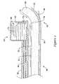
- FIG. 1is a side view of an exemplary installation tool for installing a vertebral stabilization system
- FIG. 2is an enlarged view of the distal portion of the installation tool of FIG. 1 ;
- FIG. 3is an enlarged view of the proximal portion of the installation tool of FIG. 1 with the switching member switched to a second position;
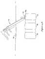
- FIGS. 4A-4Eillustrate an exemplary method of installing a vertebral stabilization system with the installation tool of FIG. 1 ;
- FIGS. 5 , 6 , 7 - 7 A, 8 , 9 A- 9 B and 10 A- 10 Billustrate various exemplary embodiments of an anchor which may be used with the installation tool of FIG. 1 ;
- FIGS. 11A-11Dillustrate various exemplary embodiments of an elongate flexible member of a vertebral stabilization system.
- stabilizationrefers to securing adjacent vertebrae such that the movement between the adjacent vertebrae is limited to a desired amount. Stabilization may also be achieved by not only reducing movement, but also by simply providing increased structural integrity between adjacent vertebrae.
- an installation tool 10configured for delivering and installing a spinal stabilization system such as a dynamic stabilization system to a spinal segment.
- the installation tool 10may be utilized to implant a spinal stabilization system to a vertebral segment in a percutaneous or minimally invasive manner.
- the installation tool 10may include a handle portion 12 and an elongate shaft 14 extending distally from the handle portion 12 .
- the elongate shaft 14may extend axially along a longitudinal axis of the installation tool 10 , while in other embodiments the elongate shaft 14 , or portions thereof, may be offset or otherwise deviate from the longitudinal axis of the installation tool 10 .
- the installation tool 10may be configured to perform one or more, or a plurality of actions in installing a vertebral stabilization system on a vertebral segment of a spinal column. For instance, the installation tool 10 may advance an elongate flexible stabilization member 50 from the distal end 16 of the shaft 14 of the installation tool 10 , may secure one or more, or a plurality of anchors to secure the elongate flexible stabilization member 50 to vertebrae of the spinal column, may distract adjacent vertebrae, and/or may cut away excess portions of the elongate flexible stabilization member 50 .
- the installation tool 10may include a conduit 20 , such as an enclosed, partially enclosed, or open conduit.
- the conduit 20may be defined, at least in part, by a first tubular member 36 of the elongate shaft 14 .
- the conduit 20may be configured to hold and direct a flexible stabilization member 50 from the distal end 16 of the installation tool 10 .
- the conduit 20through which the flexible stabilization member 50 extends through, may extend from a proximal portion of the shaft 14 to the distal end 16 of the shaft 14 along a longitudinal axis of the elongate shaft 14 .
- the elongate shaft 14may include a ramp 22 proximate the distal end 16 of the shaft 14 configured to redirect the directional movement of the stabilization member 50 upon exiting the distal opening 24 of the shaft 14 .
- the ramp 22may be an arcuate or sloped ramp extending non-parallel to the longitudinal axis of the shaft 14 .
- the distal opening 24may lie in a plane which is not perpendicular to the longitudinal axis of the shaft 14 .
- the stabilization member 50may be translated distally along the longitudinal axis of the shaft 14 until the stabilization member 50 reaches the ramp 22 , at which point, the ramp 22 redirects the stabilization member 50 out the distal opening 24 in a direction which is not parallel with the longitudinal axis of the shaft 14 .
- the stabilization member 50may be precurved such that as the stabilization member 50 exits the distal opening 24 of the installation tool 10 the stabilization member 50 attempts to revert to the precurved configuration.
- the stabilization member 50may be held in a substantially straight configuration in the conduit 20 of the shaft 14 , but may assume the curved configuration when not constrained by the conduit 20 .
- the stabilization member 50extends in a direction which is not parallel with the longitudinal axis of the shaft 14 . This may help position the stabilization member 50 along the vertebrae as the stabilization member 50 exits the shaft 14 of the installation tool 10 .
- the installation tool 10may include one or more structural features used in distracting adjacent vertebrae.
- the installation tool 10may include one or more, or a plurality of prongs 26 extending from the distal end 16 of the elongate shaft 14 .
- the prong 26may be configured to project or bite into a vertebrae during a medical procedure, such that medical personnel may use the installation tool 10 to distract the vertebra from an adjacent vertebra during the medical procedure.
- the installation tool 10may also include an anchoring mechanism 40 , which is actuatable to expel an anchor 70 from the distal end 16 of the installation tool 10 to anchor the stabilization member 50 to a vertebra.
- the anchoring mechanism 40may be a stapling mechanism configured to expel a staple from the distal end 16 of the installation tool 10 .
- the anchoring mechanism 40may be preloaded with one or more, or a plurality of anchors 70 prior to the medical procedure.
- the anchoring mechanism 40may include a cartridge 44 , such as a removable cartridge, which may house a plurality of anchors 70 for use during a medical procedure.
- the cartridge 44may feed the plurality of anchors 70 , one at a time, to a driver 46 which is actuatable to expel the anchor 70 from the installation tool 10 and drive the anchor 70 into the vertebra.
- the driver 46may be mechanically actuated, pneumatically actuated, spring actuated, or otherwise actuated to expel an anchor 70 from the installation tool 10 .
- the driver 46may extend along a second tubular member 38 of the shaft 14 of the installation tool 10 .
- the cartridge 44may include a feeding mechanism 48 , which in some instances, may include a spring member 52 configured to deliver the anchors 70 to and/or align the anchors 70 with the driver 46 to effectuate expelling the anchor 70 from the distal end 16 of the installation tool 10 .
- the cartridge 44may be loaded with a plurality of anchors 70 and then removably coupled to the elongate shaft 14 of the installation tool 10 prior to the medical procedure.
- the installation tool 10may be reused in a subsequent procedure by replacing and/or refilling the cartridge 44 .
- the installation tool 10may be preloaded with a sufficient quantity of anchors 70 to complete installation of the stabilization member 50 without withdrawing the shaft 14 of the installation tool 10 from the patient until the installation is completed.
- the cartridge 44may be preloaded with two, three, four, six, eight or more anchors 70 prior to performing the medical procedure.
- an anchor 70may be fed to the anchoring mechanism 40 by the medical personnel on demand as necessary.
- the installation tool 10may be configured such that medical personnel may manually load an anchor 70 in the installation tool 10 from the proximal end of the installation tool 10 during the medical procedure. The medical personnel may then manually install the anchor 70 into a vertebra as desired,
- an anchor 70may be disposed in a channel formed by the second tubular member 38 , or other channel of the installation tool 10 extending from a proximal portion of the shaft 14 remaining external of the patient's body to the distal end 16 of the shaft 14 .
- the channelmay be used to deliver the anchor 70 to the distal end 16 of the shaft 14 in order to be driven into the vertebra.
- the medical personnelmay then manually use a tamping device or other driver, to drive the anchor 70 into the bone. Additional anchors 70 may be loaded in the channel and individually driven into a bone by medical personnel during the medical procedure, as needed.
- the installation tool 10may include a cutter 54 which may be used to cut away an excess portion of the stabilization member 50 during a medical procedure.
- the cutter 54may extend along the shaft 14 of the installation tool 10 .
- the cutter 54may have a sharpened tip 56 which may be selectively brought into contact with the stabilization member 50 to sever a portion of the stabilization member 50 extending out of the installation tool 10 from a portion of the stabilization member 50 remaining in the conduit 20 of the installation tool 10 .
- the cutter 54may include a plurality of jaws which may be actuated toward one another to sever the stabilization member 50 positioned between the jaws of the cutter 54 . It is noted that other cutting means may be utilized with the installation tool 10 , including a separate cutting tool, to cut away excess portions of the stabilization member 50 , if desired.
- the handle portion 12 of the installation tool 10may be used to manipulate the installation tool 10 and/or to actuate one or more components of the installation tool 10 during the medical procedure.
- the handle portion 12may include a palm grip 30 rigidly mounted to a base portion 18 of the shaft 14 of the installation tool 10 .
- the palm grip 30may be ergonomically formed to fit comfortably in the palm of the hand of medical personnel using the installation tool 10 .
- the handle portion 12may also include a first trigger or actuatable handle 32 which may be used to selectively control one or more of the operative features of the installation tool 10 .
- the first actuatable handle 32may be configured to advance the stabilization member 50 from the distal end 16 of the installation tool 10 when the actuatable handle 32 is actuated.
- the first handle 32may engage with a proximal portion or extension 58 the stabilization member 50 to urge the stabilization member 50 distally.
- the first actuatable handle 32may be pivotably mounted to the shaft 14 such that the first actuatable handle 32 may be actuated relative to the palm grip 30 . Actuation of the first actuatable handle 32 may urge to stabilization member 50 distally along the conduit 20 to advance the stabilization member 50 from the distal opening 24 .
- the handle portion 12may include a spring 28 or other biasing means biasing the first actuatable handle 32 away from the palm grip 30 .
- advancement of the stabilization member 50may be performed by actuating the first handle 32 toward the palm grip 30 .
- a single stroke of the first handle 32may advance the stabilization member 50 from the installation tool 10 a sufficient distance.
- a series of strokes of the first handle 32 toward the palm grip 30may be performed, in which the stabilization member 50 moves more distally from the installation tool 10 during each of the series of strokes.
- the handle portion 12may include a second trigger or actuatable handle 34 which may be used to selectively control one or more of the operative features of the installation tool 10 .
- the second actuatable handle 34may be configured to actuate the driver 46 to expel an anchor 70 from the installation tool 10 when the second handle 34 is actuated.
- the second handle 34may operate and/or release, a lever, valve, cam, rod, spring, or other mechanism of the anchoring mechanism 40 to expel an anchor 70 from the installation tool 10 .
- the second actuatable handle 34may be pivotably mounted to the shaft 14 such that the second actuatable handle 34 may be actuated relative to the palm grip 30 . Actuation of the second actuatable handle 34 may initiate activation of the driver 46 to expel an anchor 70 from the installation tool 10 . For instance, the second actuatable handle 34 may be moved toward the palm grip 30 in order to expel an anchor 70 from the installation tool 10 . Thus, an anchor 70 may be discharged from the installation tool 10 with each stroke of the second handle 34 in some instances.
- first and/or second actuatable handles 32 , 34may be selectively used to selectively control the cutter 54 , or the installation tool 10 may include a third trigger or actuatable handle to control the cutter 54 .
- the first actuatable handle 32may selectively control actuation of the cutter 54 .
- the installation tool 10may include a control mechanism 60 , such as a button, switch, toggle, clip, lever, or other feature, which may be manipulated to selectively control operation of the first actuatable handle 32 .
- a control mechanism 60such as a button, switch, toggle, clip, lever, or other feature, which may be manipulated to selectively control operation of the first actuatable handle 32 .
- actuation of the first handle 32may advance the stabilization member 50 from the installation tool 10 .
- actuation of the first handle 32may actuate the cutter 54 to sever the stabilization member 50 as discussed above.
- actuation of the first handle 32may force the control mechanism 60 against a proximal portion of the cutter 54 , urging the cutter 54 distally to cut the stabilization member 50 .
- actuation of the first handle 32may not result in actuation of the cutter 54 .
- the second actuatable handle 32may include a control mechanism which may selectively control actuation of a plurality of operative features of the installation tool 10 .
- FIGS. 4A-4Eillustrate an exemplary method of installing a vertebral stabilization system 80 with the installation tool 10 during a medical procedure.
- the spinal column of a patientmay be accessed in a percutaneous or minimally invasive manner by passing the shaft 14 of the installation tool 10 through an incision 90 .
- an access cannula, retractor, or other device(not shown) may be inserted into the incision 90 to maintain access to adjacent vertebrae 2 a , 2 b during the medical procedure.
- access to the adjacent vertebrae 2 a , 2 bmay be maintained directly through the incision 90 .
- the vertebrae 2 a , 2 bmay be accessed through a posterior approach, an anterior approach, a lateral approach, a translateral approach, a posterio-lateral approach, or other desired approach.
- the distal end 16 of the installation instrument 10may be moved adjacent to the first vertebra 2 a and a portion of the stabilization member 50 may be advanced out of the distal end 16 of the installation instrument 10 .
- the first handle 32may be actuated to move the stabilization member 50 distally out of the distal opening 24 of the installation tool 10 .
- the ramp 22may redirect the exposed portion of the stabilization member 50 in a direction generally parallel to the spinal column, while the elongate shaft 14 is positioned at an angle, such as an acute angle, to the spinal column.
- the anchoring mechanism 40may be actuated to drive a first anchor 70 a into the first vertebra 2 a to secure the stabilization member 50 to the first vertebra 2 a .
- the second handle 34may be actuated to actuate the driver 46 to push the first anchor 70 a from the distal end 16 of the installation tool 10 .
- the first anchor 70 amay be driven into the first vertebra 2 a through direct translational movement of the first anchor 70 a , without rotational movement such as is necessary in installing a pedicle screw. Thus, the first anchor 70 a may be installed more quickly than the time necessary to secure a pedicle screw. Note, as discussed above, in some embodiments the first anchor 70 a may be driven into the first vertebra 2 a by manually delivering and tamping the first anchor 70 a into place through a channel along the shaft 14 , or otherwise manually driven into the first vertebra 2 a.
- the distal end 16 of the installation tool 10may be moved toward the second vertebra 2 b , as shown in FIG. 4B .
- the stabilization member 50may be further advanced from the distal end 16 of the installation tool 10 , extending the stabilization member 50 from the first vertebra 2 a to the second vertebra 2 b .
- the first handle 32may be actuated as the distal end 16 of the installation tool 10 is moved to the second vertebra 2 b to advance the stabilization member 50 along the conduit 20 and out the distal opening 24 of the installation tool 10 .
- the installation tool 10may be used to distract the second vertebra 2 b from the first vertebra 2 a to alleviate compression of the spinal column and/or attain a desired spacing between the first vertebra 2 a and the second vertebra 2 b .
- the prong(s) 26 of the installation tool 10may be engaged with the second vertebra 2 b and the installation tool 10 may be manipulated to urge the second vertebra 2 b away from the first vertebra 2 a .
- a separate distraction toolmay be used independently or in conjunction with the installation tool 10 to distract the second vertebra 2 b from the first vertebra 2 a.
- the stabilization member 50may be positioned at a desired location on the second vertebra 2 b , such as the pedicle, vertebral body, spinous process, lamina, facet, other posterior bony structures, or other region of the second vertebra 2 b . Having completed distraction of the vertebrae 2 a , 2 b , if any, the anchoring mechanism 40 may then be actuated to drive a second anchor 70 b into the second vertebra 2 b to secure the stabilization member 50 to the second vertebra 2 b , as shown in FIG. 4C .
- the second handle 34may be actuated to actuate the driver 46 to push the second anchor 70 b from the distal end 16 of the installation tool 10 .
- the second anchor 70 bmay be driven into the second vertebra 2 b through direct translational movement of the second anchor 70 b , without rotational movement such as is necessary in installing a pedicle screw.
- the second anchor 70 bmay be installed more quickly than the time necessary to secure a pedicle screw.
- the second anchor 70 bmay be driven into the second vertebra 2 b by manually delivering and tamping the second anchor 70 b into place through a channel along the shaft 14 , or otherwise manually driven into the second vertebra 2 b.
- any excess portion of the stabilization member 50may be cut away from the portion of the stabilization member 50 extending between the first anchor 70 a and the second anchor 70 b .
- the cutter 54may be actuated to cut away excess portions of the stabilization member 50 . This may be achieved, for example, by manipulating the control mechanism 60 such that actuation of the first handle 32 moves the cutter 54 distally allowing the sharpened tip 56 of the cutter 54 to sever the stabilization member 50 .
- the cutter 54may include jaws which close around the stabilization member 50 through actuation of the first handle 32 to sever the stabilization member 50 .
- another cutting devicemay be introduced through the incision 90 to cut away excess portions of the stabilization member 50 .
- FIG. 4Eillustrates the installed vertebral stabilization system 80 , including the stabilization member 50 and the first and second anchors 70 a , 70 b securing the stabilization member 50 to first and second vertebra 2 a , 2 b , respectively.
- the stabilization member 50may provide tensile strength and/or compressive resistance in order to transfer loading of the spinal column.
- the flexible nature of the stabilization member 50may allow for some dynamic movement of the adjacent vertebrae 2 a , 2 b relative to each other.
- the installation tool 10may be used to install the stabilization member 50 , or another stabilization member 50 , across additional vertebrae in a multi-level stabilization system. For instance if it is desired to install the stabilization member across one or more additional vertebrae 2 in a multi-level stabilization system, once the stabilization member 50 has been secured to the second vertebra 2 b , the installation tool 10 may be moved toward a third vertebra 2 c while advancing the stabilization member 50 from the distal end 16 of the installation tool 10 in a similar manner to that described above.
- the anchoring mechanism 40may be actuated to secure the stabilization member 50 to the third vertebra 2 c with an anchor 70 in a similar manner to that described above. These steps may be repeated for additional vertebral levels as desired. Any excess portions of the stabilization member 50 may then be cut away, such as with the cutter 54 , and then the installation tool 10 may be removed from the patient.
- FIGS. 5 , 6 , 7 - 7 A, 8 , 9 A- 9 B and 10 A- 10 Billustrate some possible configurations of the anchor 70 which may be used with the installation tool 10 to secure a stabilization member 50 to vertebrae of a spinal column.
- FIG. 5illustrates a staple 170 which may be used to secure a stabilization member 50 to vertebrae.
- the staple 170includes a first leg 171 , a second leg 172 and a crown 173 extending between the first leg 171 and the second leg 172 .
- the first leg 171may extend parallel to the second leg 172 , while in other embodiments the first leg 171 may be divergent from or convergent to the second leg 172 .
- the crown 173may have an arcuate shape curving from the first leg 171 to the second leg 172 . Such an arcuate shape may accommodate the shape of a stabilization member 50 such that a convex surface of the stabilization member 50 may rest against or contact a concave surface of the arcuate portion of the crown 173 . In other embodiments, the crown 173 may extend linearly between the first leg 171 and the second leg 172 of the staple 170 .
- the first leg 171 and/or the second leg 172may include one or more, or a plurality of barbs 174 which may be embedded in the bone of a vertebra to help secure and retain the staple 170 with the vertebra.
- the barbs 174may prevent reverse movement of the legs 171 , 172 out of the bone.
- the crown 173may include a spike 175 or other projection configured to protrude into and/or penetrate the stabilization member 50 .
- the spike 175may help prevent movement of the stabilization member 50 relative to the staple 170 when the stabilization member 50 is secured to the vertebra.
- the stabilization member 50When secured to a vertebra, the stabilization member 50 may extend through the central opening of the staple 170 such that the first and second legs 171 , 172 of the staple 170 straddle the stabilization member 50 while the stabilization member 50 is positioned between the crown 173 and the vertebra.
- FIG. 6illustrates another staple 270 which may be used to secure a stabilization member 50 to vertebrae.
- the staple 270includes a first leg 271 , a second leg 272 and a crown 273 extending between the first leg 271 and the second leg 272 .
- the first leg 271may extend parallel to the second leg 272 , while in other embodiments the first leg 271 may be divergent from or convergent to the second leg 272 .
- the crown 273may have an arcuate shape curving from the first leg 271 to the second leg 272 .
- Such an arcuate shapemay accommodate the shape of a stabilization member 50 such that a convex surface of the stabilization member 50 may rest against or contact a concave surface of the arcuate portion of the crown 273 .
- the crown 273may extend linearly between the first leg 271 and the second leg 272 of the staple 270 .
- the first leg 271 and/or the second leg 272may include one or more, or a plurality of barbs 274 which may be embedded in the bone of a vertebra to help secure and retain the staple 270 with the vertebra.
- the barbs 274may prevent reverse movement of the legs 271 , 272 out of the bone.
- the crown 273may include a plurality of projections 275 configured to protrude into and/or penetrate the stabilization member 50 .
- the plurality of projections 275may extend from the crown 273 along a length of the crown 273 of the staple 270 .
- the plurality of projections 275may help prevent movement of the stabilization member 50 relative to the staple 270 when the stabilization member 50 is secured to the vertebra.
- the staple 270may also include a first ridge 276 on the first leg 271 and a second ridge 277 on the second leg 272 .
- the first ridge 276may extend toward the second leg 272 and the second ridge 277 may extend toward the first leg 271 .
- the first and second ridges 276 , 277may be configured such that the ridges 276 , 277 are located on an under side of the stabilization member 50 (i.e., between the stabilization member 50 and the vertebra), when the stabilization member 50 is secured to the vertebra with the staple 270 .
- the ridges 276 , 277may help force the stabilization member 50 upward into engagement with the projections 275 protruding from the crown 273 to help retain the stabilization member 50 from moving relative to the staple 270 when secured to a vertebra.
- the stabilization member 50may be snap fitted into the opening defined between the crown 273 and the first and second ridges 276 , 277 to increase the holding ability of the staple 270 .
- the stabilization member 50When secured to a vertebra, the stabilization member 50 may extend through the central opening of the staple 270 such that the first and second legs 271 , 272 of the staple 270 straddle the stabilization member 50 while the stabilization member 50 is positioned between the crown 273 and the vertebra.
- FIGS. 7 and 7AAnother embodiment of a staple 370 is illustrated in FIGS. 7 and 7A .
- the staple 370includes a first leg 371 , a second leg 372 and a crown 373 extending between the first leg 371 and the second leg 372 .
- the first leg 371may extend parallel to the second leg 372 , while in other embodiments the first leg 371 may be divergent from or convergent to the second leg 372 .
- the crown 373may have an arcuate shape curving from the first leg 371 to the second leg 372 .
- Such an arcuate shapemay accommodate the shape of a stabilization member 50 such that a convex surface of the stabilization member 50 may rest against or contact a concave surface of the arcuate portion of the crown 373 .
- the crown 373may extend linearly between the first leg 371 and the second leg 372 of the staple 370 .
- the first leg 371 and/or the second leg 372may include one or more, or a plurality of barbs 374 which may be embedded in the bone of a vertebra to help secure and retain the staple 370 with the vertebra.
- the barbs 374may prevent reverse movement of the legs 371 , 372 out of the bone.
- the crown 373may include a first rib 377 and a second rib 378 extending parallel to the first rib 377 along an inner surface of the crown.
- the first and second ribs 377 , 378may be arcuate, following the arcuate curvature of the crown 373 .
- the crown 373may include a channel 379 between the first rib 377 and the second rib 378 .
- the first and second ribs 377 , 378may engage the stabilization member 50 when the stabilization member 50 is secured to a vertebra with the staple 370 in order to help prevent movement of the stabilization member 50 relative to the staple 270 when the stabilization member 50 is secured to the vertebra.
- the stabilization member 50When secured to a vertebra, the stabilization member 50 may extend through the central opening of the staple 370 such that the first and second legs 371 , 372 of the staple 370 straddle the stabilization member 50 while the stabilization member 50 is positioned between the crown 373 and the vertebra.
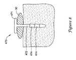
- FIG. 8illustrates a tack 470 which may be used to secure a stabilization member 50 to vertebrae.
- the tack 470may include a head 471 and a shaft 472 extending from the head 471 .
- the shaft 472may include one or more, or a plurality of barbs 474 which may be embedded in the bone of a vertebra to help secure and retain the tack 470 with the vertebra. For instance, the barbs 474 may prevent reverse movement of the tack 470 out of the bone.
- the tack 470When secured to a vertebra, the tack 470 may pierce the stabilization member 50 such that the head 471 presses against the stabilization member 50 while the shaft 472 extends through the stabilization member 50 and into the vertebra.
- the stabilization member 50may include a hole through which the shaft 472 of the tack 470 extends through.
- FIGS. 9A-9BAnother staple 570 which may be used to secure a stabilization member 50 to vertebrae is shown in FIGS. 9A-9B .
- the staple 570includes a first leg 571 , a second leg 572 and a crown 573 extending between the first leg 571 and the second leg 572 .
- initially the first leg 571may extend parallel to the second leg 572 .
- the crown 573may have an arcuate shape curving from the first leg 571 to the second leg 572 .
- Such an arcuate shapemay accommodate the shape of a stabilization member 50 such that a convex surface of the stabilization member 50 may rest against or contact a concave surface of the arcuate portion of the crown 573 .
- the crown 573may extend linearly between the first leg 571 and the second leg 572 of the staple 570 .
- the first leg 571 and/or the second leg 572may include one or more, or a plurality of barbs 574 which may be embedded in the bone of a vertebra to help secure and retain the staple 570 with the vertebra.
- the barbs 574may prevent reverse movement of the legs 571 , 572 out of the bone.
- the crown 573may include a plurality of projections 575 configured to protrude into and/or penetrate the stabilization member 50 .
- the plurality of projections 575may extend lateral toward one another between the first leg 571 and the second leg 572 .
- the plurality of projections 575may help prevent movement of the stabilization member 50 relative to the staple 570 when the stabilization member 50 is secured to the vertebra.
- the stabilization member 50When secured to a vertebra, the stabilization member 50 may extend through the central opening of the staple 570 such that the first and second legs 571 , 572 of the staple 570 straddle the stabilization member 50 while the stabilization member 50 is positioned between the crown 573 and the vertebra. As shown in FIG. 9B , with the stabilization member 50 positioned between the first and second legs 571 , 572 , the legs 571 , 572 may be laterally crimped toward one another to secure the stabilization member 50 between the legs 571 , 572 . Crimping of the legs 571 , 572 may force the projections 575 into engagement with the stabilization member 50 such that the projections 575 project into and/or penetrate the stabilization member 50 . Crimping the staple 570 may help prevent movement of the stabilization member 50 relative to the staple 570 when the stabilization member 50 is secured to the vertebra.
- FIGS. 10A-10BYet another staple 670 which may be used to secure a stabilization member 50 to vertebrae is shown in FIGS. 10A-10B .
- the staple 670includes a first leg 671 , a second leg 672 and a cross member 673 extending between the first leg 671 and the second leg 672 .
- the first leg 671may extend parallel to the second leg 672 , while in other embodiments the first leg 671 may be divergent from or convergent to the second leg 672 .
- the staple 670may also include a first arm 677 and a second arm 678 extending from the cross member 673 in a direction generally opposite that of the first and second legs 671 , 672 .
- the first and second arms 677 , 678may be extensions of the first and second legs 671 , 672 , respectively, extending in opposing directions from the cross member 673 .
- the staple 670may have a generally H-shape in which the first leg 671 extends parallel to the second leg 672 , and the first arm 677 extends parallel to the second arm 678 .
- the cross member 673may have an arcuate shape curving from the first leg 671 and first arm 677 to the second leg 672 and second arm 678 .
- Such an arcuate shapemay accommodate the shape of a stabilization member 50 such that a convex surface of the stabilization member 50 may rest against or contact a concave surface of the arcuate portion of the cross member 673 .
- the cross member 673may extend linearly from the first leg 671 and first arm 677 to the second leg 672 and second arm 678 of the staple 670 .
- the first leg 671 and/or the second leg 672may include one or more, or a plurality of barbs 674 which may be embedded in the bone of a vertebra to help secure and retain the staple 670 with the vertebra.
- the barbs 674may prevent reverse movement of the legs 671 , 672 out of the bone.
- the first arm 677 and/or the second arm 678may include one or more, or a plurality of projections 675 configured to protrude into and/or penetrate the stabilization member 50 .
- the projections 675may extend lateral toward one another between the first arm 677 and the second arm 678 .
- the projections 675may help prevent movement of the stabilization member 50 relative to the staple 670 when the stabilization member 50 is secured to the vertebra.
- the stabilization member 50When secured to a vertebra, the stabilization member 50 may extend through the central opening of the staple 670 between the first and second arms 677 , 678 such that the first and second arms 677 , 678 of the staple 670 straddle the stabilization member 50 . Furthermore, the cross member 673 may be located between the stabilization member 50 and the vertebra. As shown in FIG. 10B , with the stabilization member 50 positioned between the first and second arms 677 , 678 , the arms 677 , 678 may be crimped around a portion of the stabilization member 50 to secure the stabilization member 50 between the arms 677 , 678 and the cross member 673 .
- the arms 677 , 678may be crimped into an arcuate shape around a portion of the perimeter of the stabilization member 50 . Crimping of the first and second arms 677 , 678 may force the projections 675 into engagement with the stabilization member 50 such that the projections 675 project into and/or penetrate the stabilization member 50 . Crimping the staple 670 may help prevent movement of the stabilization member 50 relative to the staple 670 when the stabilization member 50 is secured to the vertebra.
- FIGS. 11A-11Dillustrate some possible configurations of the stabilization member 50 which may provide tensile strength and compressive resistance.
- the stabilization member 150may include an outer layer 152 surrounding an inner core layer 154 .
- the outer layer 152may provide tensile strength while the inner core layer 154 may provide compressive resistance to the stabilization member 150 .
- the outer layer 152may be a knit, braided or woven jacket of material overlaying the inner core layer 154 which may be placed in tension.
- the inner core layer 154may be formed of a solid material, such as a solid polymeric material (e.g., an elastomer), which may be placed in compression.
- FIG. 11Billustrates another stabilization member 250 which may be subjected to tensile and compressive loading.
- the stabilization member 250may include an inner core layer 256 , an intermediate layer 254 surrounding the inner core layer 256 , and an outer layer 252 surrounding the intermediate layer 254 .
- the inner core layer 256may include one or more filaments or strands intermingled (e.g., twisted, woven, braided, knitted) together.
- the intermediate layer 254may be formed of a solid material, such as a solid polymeric material (e.g., an elastomer), placed or formed over the inner core layer 256 .
- the outer layer 252may be a knit, braided or woven jacket of material overlaying the intermediate layer 254 .
- the inner core layer 256 and/or the outer layer 252may transfer tensile loads through the stabilization member 250 and the intermediate layer 254 may transfer compressive loads through the stabilization member 250 .
- FIG. 11Cillustrates another stabilization member 350 which may be subjected to tensile and compressive loading.
- the stabilization member 350may include an outer layer 352 surrounding an inner core layer 354 .
- the outer layer 352may provide tensile strength while the inner core layer 354 may provide compressive resistance to the stabilization member 350 .
- the outer layer 352may be a knit, braided or woven jacket of material overlaying the inner core layer 354 which may be placed in tension.
- the inner core layer 354may be formed of a solid material, such as a solid polymeric material (e.g., an elastomer), which may be placed in compression. As shown in FIG.
- the inner core layer 354may have an oval, or flattened cross section, which may allow for a larger surface area of the stabilization member 350 to be in contact with the vertebrae of the spinal column, without deformation of the stabilization member 350 .
- the outer layer 352may transfer tensile loads through the stabilization member 350 and the inner core layer 354 may transfer compressive loads through the stabilization member 350 .
- FIG. 11Dillustrates yet another stabilization member 450 which may be subjected to tensile and compressive loading.
- the stabilization member 450may include a first core layer 454 and a second core layer 456 extending axially through an outer layer 452 .
- the first core layer 454may be spaced from the second core layer 456 and extending parallel to the second core layer 456 along the length of the stabilization member 450 .
- Each of the first core layer 454 and the second core layer 456may include one or more filaments or strands intermingled (e.g., twisted, woven, braided, knitted) together.
- the outer layer 452may be formed of a solid material, such as a solid polymeric material (e.g., an elastomer), placed or formed over the first and second inner core layers 454 , 456 . As shown in FIG. 11D , the outer layer 452 may have an oval, or flattened cross section, which may allow for a larger surface area of the stabilization member 450 to be in contact with the vertebrae of the spinal column, without deformation of the stabilization member 450 . Furthermore, in some instances, an anchor may penetrate the central portion of the outer layer 452 between the first and second inner core layers 454 , 456 to secure the stabilization member 450 to a vertebra. The first and second inner core layers 454 , 456 may transfer tensile loads through the stabilization member 450 and the outer layer 452 may transfer compressive loads through the stabilization member 450 .
- a solid polymeric materiale.g., an elastomer
- the stabilization member 50may be a monolithic structure formed of a single piece of flexible material, including natural or synthetic elastomers, thermoplastic elastomers, for example, polyurethane elastomers such as polycarbonate urethane, or other polymeric materials.
- the stabilization member 50may be molded, extruded, or otherwise formed from a desired material. In such an embodiment, the stabilization member 50 may be able to withstand both tensile and compressive loads, as desired.
Landscapes
- Health & Medical Sciences (AREA)
- Orthopedic Medicine & Surgery (AREA)
- Surgery (AREA)
- Life Sciences & Earth Sciences (AREA)
- Neurology (AREA)
- Molecular Biology (AREA)
- Heart & Thoracic Surgery (AREA)
- Medical Informatics (AREA)
- Biomedical Technology (AREA)
- Animal Behavior & Ethology (AREA)
- General Health & Medical Sciences (AREA)
- Public Health (AREA)
- Veterinary Medicine (AREA)
- Engineering & Computer Science (AREA)
- Nuclear Medicine, Radiotherapy & Molecular Imaging (AREA)
- Rheumatology (AREA)
- Surgical Instruments (AREA)
- Prostheses (AREA)
Abstract
Description
Claims (8)
Priority Applications (8)
| Application Number | Priority Date | Filing Date | Title |
|---|---|---|---|
| US12/334,031US8137355B2 (en) | 2008-12-12 | 2008-12-12 | Spinal stabilization installation instrumentation and methods |
| US13/418,403US8465493B2 (en) | 2008-12-12 | 2012-03-13 | Spinal stabilization installation instrumentation and methods |
| US13/872,446US8821550B2 (en) | 2008-12-12 | 2013-04-29 | Spinal stabilization installation instrumentation and methods |
| US14/332,873US9468475B2 (en) | 2008-12-12 | 2014-07-16 | Spinal stabilization installation instrumentation and methods |
| US15/265,444US10376293B2 (en) | 2008-12-12 | 2016-09-14 | Spinal stabilization installation instrumentation and methods |
| US16/456,321US11432853B2 (en) | 2008-12-12 | 2019-06-28 | Spinal stabilization installation instrumentation and methods |
| US17/848,195US12167875B2 (en) | 2008-12-12 | 2022-06-23 | Spinal stabilization installation instrumentation and methods |
| US18/972,460US20250099142A1 (en) | 2008-12-12 | 2024-12-06 | Spinal stabilization installation instrumentation and methods |
Applications Claiming Priority (1)
| Application Number | Priority Date | Filing Date | Title |
|---|---|---|---|
| US12/334,031US8137355B2 (en) | 2008-12-12 | 2008-12-12 | Spinal stabilization installation instrumentation and methods |
Related Child Applications (1)
| Application Number | Title | Priority Date | Filing Date |
|---|---|---|---|
| US13/418,403ContinuationUS8465493B2 (en) | 2008-12-12 | 2012-03-13 | Spinal stabilization installation instrumentation and methods |
Publications (2)
| Publication Number | Publication Date |
|---|---|
| US20100152790A1 US20100152790A1 (en) | 2010-06-17 |
| US8137355B2true US8137355B2 (en) | 2012-03-20 |
Family
ID=42241466
Family Applications (8)
| Application Number | Title | Priority Date | Filing Date |
|---|---|---|---|
| US12/334,031Active2030-03-26US8137355B2 (en) | 2008-12-12 | 2008-12-12 | Spinal stabilization installation instrumentation and methods |
| US13/418,403ActiveUS8465493B2 (en) | 2008-12-12 | 2012-03-13 | Spinal stabilization installation instrumentation and methods |
| US13/872,446ActiveUS8821550B2 (en) | 2008-12-12 | 2013-04-29 | Spinal stabilization installation instrumentation and methods |
| US14/332,873ActiveUS9468475B2 (en) | 2008-12-12 | 2014-07-16 | Spinal stabilization installation instrumentation and methods |
| US15/265,444Active2029-02-05US10376293B2 (en) | 2008-12-12 | 2016-09-14 | Spinal stabilization installation instrumentation and methods |
| US16/456,321Active2029-01-16US11432853B2 (en) | 2008-12-12 | 2019-06-28 | Spinal stabilization installation instrumentation and methods |
| US17/848,195Active2029-06-23US12167875B2 (en) | 2008-12-12 | 2022-06-23 | Spinal stabilization installation instrumentation and methods |
| US18/972,460PendingUS20250099142A1 (en) | 2008-12-12 | 2024-12-06 | Spinal stabilization installation instrumentation and methods |
Family Applications After (7)
| Application Number | Title | Priority Date | Filing Date |
|---|---|---|---|
| US13/418,403ActiveUS8465493B2 (en) | 2008-12-12 | 2012-03-13 | Spinal stabilization installation instrumentation and methods |
| US13/872,446ActiveUS8821550B2 (en) | 2008-12-12 | 2013-04-29 | Spinal stabilization installation instrumentation and methods |
| US14/332,873ActiveUS9468475B2 (en) | 2008-12-12 | 2014-07-16 | Spinal stabilization installation instrumentation and methods |
| US15/265,444Active2029-02-05US10376293B2 (en) | 2008-12-12 | 2016-09-14 | Spinal stabilization installation instrumentation and methods |
| US16/456,321Active2029-01-16US11432853B2 (en) | 2008-12-12 | 2019-06-28 | Spinal stabilization installation instrumentation and methods |
| US17/848,195Active2029-06-23US12167875B2 (en) | 2008-12-12 | 2022-06-23 | Spinal stabilization installation instrumentation and methods |
| US18/972,460PendingUS20250099142A1 (en) | 2008-12-12 | 2024-12-06 | Spinal stabilization installation instrumentation and methods |
Country Status (1)
| Country | Link |
|---|---|
| US (8) | US8137355B2 (en) |
Cited By (6)
| Publication number | Priority date | Publication date | Assignee | Title |
|---|---|---|---|---|
| US9192415B1 (en) | 2008-02-06 | 2015-11-24 | Nuvasive, Inc. | Systems and methods for holding and implanting bone anchors |
| US9198698B1 (en) | 2011-02-10 | 2015-12-01 | Nuvasive, Inc. | Minimally invasive spinal fixation system and related methods |
| US9468475B2 (en) | 2008-12-12 | 2016-10-18 | Zimmer Spine, Inc. | Spinal stabilization installation instrumentation and methods |
| US9974577B1 (en) | 2015-05-21 | 2018-05-22 | Nuvasive, Inc. | Methods and instruments for performing leveraged reduction during single position spine surgery |
| US10398481B2 (en) | 2016-10-03 | 2019-09-03 | Nuvasive, Inc. | Spinal fixation system |
| US11051861B2 (en) | 2018-06-13 | 2021-07-06 | Nuvasive, Inc. | Rod reduction assemblies and related methods |
Families Citing this family (19)
| Publication number | Priority date | Publication date | Assignee | Title |
|---|---|---|---|---|
| US8323341B2 (en) | 2007-09-07 | 2012-12-04 | Intrinsic Therapeutics, Inc. | Impaction grafting for vertebral fusion |
| US7094258B2 (en) | 1999-08-18 | 2006-08-22 | Intrinsic Therapeutics, Inc. | Methods of reinforcing an annulus fibrosis |
| CA2425951C (en)* | 1999-08-18 | 2008-09-16 | Intrinsic Therapeutics, Inc. | Devices and method for nucleus pulposus augmentation and retention |
| US7998213B2 (en) | 1999-08-18 | 2011-08-16 | Intrinsic Therapeutics, Inc. | Intervertebral disc herniation repair |
| EP1624832A4 (en) | 1999-08-18 | 2008-12-24 | Intrinsic Therapeutics Inc | Devices and method for augmenting a vertebral disc nucleus |
| US7717961B2 (en) | 1999-08-18 | 2010-05-18 | Intrinsic Therapeutics, Inc. | Apparatus delivery in an intervertebral disc |
| US7972337B2 (en) | 2005-12-28 | 2011-07-05 | Intrinsic Therapeutics, Inc. | Devices and methods for bone anchoring |
| EP2208481B1 (en) | 2007-07-27 | 2016-12-28 | R Tree Innovations, LLC | Inter-Body Implantation System |
| US20110196492A1 (en) | 2007-09-07 | 2011-08-11 | Intrinsic Therapeutics, Inc. | Bone anchoring systems |
| ES2563172T3 (en)* | 2009-07-09 | 2016-03-11 | R Tree Innovations, Llc | Flexible intersomatic implant |
| US8864777B2 (en)* | 2011-01-28 | 2014-10-21 | Anchor Orthopedics Xt Inc. | Methods for facilitating tissue puncture |
| US9907582B1 (en) | 2011-04-25 | 2018-03-06 | Nuvasive, Inc. | Minimally invasive spinal fixation system and related methods |
| US20130110174A1 (en)* | 2011-10-31 | 2013-05-02 | Warsaw Orthopedic, Inc. | Methods for installing a vertebral construct |
| US20140074161A1 (en)* | 2012-09-07 | 2014-03-13 | Mimosa Medical, Inc. | Wound closure devices and methods of use |
| ES2804126T3 (en) | 2014-02-24 | 2021-02-03 | Univ Curtin Tech | Bra |
| WO2017045148A1 (en)* | 2015-09-16 | 2017-03-23 | 瑞奇外科器械(中国)有限公司 | Action execution apparatus and ultrasound surgical instrument |
| US10194960B1 (en) | 2015-12-03 | 2019-02-05 | Nuvasive, Inc. | Spinal compression instrument and related methods |
| WO2017156596A1 (en) | 2016-03-18 | 2017-09-21 | Curtin University Of Technology | An expandable fastener for orthopaedic applications |
| TWI611793B (en)* | 2017-04-12 | 2018-01-21 | 長庚醫療財團法人林口長庚紀念醫院 | Guiding apparatus for minimally invasive pedicle screws insertion |
Citations (67)
| Publication number | Priority date | Publication date | Assignee | Title |
|---|---|---|---|---|
| NL7610576A (en) | 1976-09-23 | 1978-03-29 | Gerard Hendrik Slot | Spinal column repositioning system - uses tongs to position screws in column sections before securing to rope |
| US4414967A (en) | 1981-06-22 | 1983-11-15 | Minnesota Mining And Manufacturing Company | Internal fixation of bone, tendon, and ligaments |
| US4454875A (en) | 1982-04-15 | 1984-06-19 | Techmedica, Inc. | Osteal medical staple |
| US4500025A (en) | 1983-07-18 | 1985-02-19 | Minnesota Mining And Manufacturing Company | Bone stapler |
| US4527726A (en) | 1983-07-18 | 1985-07-09 | Minnesota Mining And Manufacturing Company | Bone stapler |
| US4570623A (en) | 1983-06-02 | 1986-02-18 | Pfizer Hospital Products Group Inc. | Arched bridge staple |
| EP0516567A1 (en) | 1991-05-30 | 1992-12-02 | Société dite: "PSI" | Shock-absorbing device for intervertebral stabilisation |
| US5352229A (en) | 1993-05-12 | 1994-10-04 | Marlowe Goble E | Arbor press staple and washer and method for its use |
| WO1995019149A1 (en) | 1994-01-18 | 1995-07-20 | Safir S.A.R.L. | Global vertebral fixation device |
| EP0669109A1 (en) | 1994-02-28 | 1995-08-30 | SULZER Medizinaltechnik AG | Stabilizer for adjacent vertebrae |
| US5575054A (en) | 1994-10-06 | 1996-11-19 | Minnesota Mining And Manufacturing Company | Bone stapler cartridge |
| US5720753A (en) | 1991-03-22 | 1998-02-24 | United States Surgical Corporation | Orthopedic fastener |
| WO1999005980A1 (en) | 1997-07-31 | 1999-02-11 | Plus Endoprothetik Ag | Device for stiffening and/or correcting a vertebral column or such like |
| FR2775583A1 (en) | 1998-03-04 | 1999-09-10 | Dimso Sa | SYSTEM FOR OSTEOSYNTHESIS OF THE RACHIS WITH LIGAMENT |
| US6146406A (en) | 1998-02-12 | 2000-11-14 | Smith & Nephew, Inc. | Bone anchor |
| US6616669B2 (en) | 1999-04-23 | 2003-09-09 | Sdgi Holdings, Inc. | Method for the correction of spinal deformities through vertebral body tethering without fusion |
| FR2844180A1 (en) | 2002-09-11 | 2004-03-12 | Spinevision | Connection element for spinal fixation system designed to link at least two implantable connection assemblies, is formed from a helicoidal spring part and a polymeric material support part |
| WO2004089244A2 (en) | 2003-04-04 | 2004-10-21 | Stephen Ritland | Dynamic fixation device and method of use |
| EP1523949A1 (en) | 2003-10-17 | 2005-04-20 | BIEDERMANN MOTECH GmbH | Surgical rod element, stabilisation device, and method of manufacturing the element |
| WO2005037150A1 (en) | 2003-10-16 | 2005-04-28 | Osteotech, Inc. | System and method for flexible correction of bony motion segment |
| WO2005037110A2 (en) | 2003-10-21 | 2005-04-28 | Sdgi Holdings, Inc. | Dynamizable orthopedic implants and their use in treating bone defects |
| FR2867057A1 (en) | 2004-03-02 | 2005-09-09 | Spinevision | Connecting element, useful for a spinal fixing system to connect two entire implantable connection bodies comprises a cable and a polymer envelope surrounding the cable |
| WO2006066685A1 (en) | 2004-12-17 | 2006-06-29 | Zimmer Gmbh | Intervertebral stabilisation system |
| US20070005063A1 (en) | 2005-06-20 | 2007-01-04 | Sdgi Holdings, Inc. | Multi-level multi-functional spinal stabilization systems and methods |
| US20070078461A1 (en) | 2005-09-27 | 2007-04-05 | Shluzas Alan E | Methods and apparatuses for stabilizing the spine through an access device |
| WO2007044795A2 (en) | 2005-10-11 | 2007-04-19 | Applied Spine Technologies, Inc. | Dynamic spinal stabilization systems |
| US20070100341A1 (en) | 2004-10-20 | 2007-05-03 | Reglos Joey C | Systems and methods for stabilization of bone structures |
| US20070118119A1 (en) | 2005-11-18 | 2007-05-24 | Zimmer Spine, Inc. | Methods and device for dynamic stabilization |
| US20070156245A1 (en)* | 1999-10-20 | 2007-07-05 | Cauthen Joseph C Iii | Method and apparatus for the treatment of the intervertebral disc annulus |
| WO2007087476A1 (en) | 2006-01-27 | 2007-08-02 | Warsaw Orthopedic, Inc. | Spinal rods having different flexural rigidities about different axes and methods of use |
| US20070198088A1 (en) | 2003-10-17 | 2007-08-23 | Lutz Biedermann | Flexible implant |
| US20070225710A1 (en) | 2003-09-24 | 2007-09-27 | Tae-Ahn Jahng | Spinal stabilization device |
| US20070233087A1 (en) | 2004-07-12 | 2007-10-04 | Fridolin Schlapfer | Device for the dynamic fixation of bones |
| US20070233075A1 (en) | 2006-03-16 | 2007-10-04 | Zimmer Spine, Inc. | Spinal fixation device with variable stiffness |
| US20070233095A1 (en) | 2004-10-07 | 2007-10-04 | Schlaepfer Fridolin J | Device for dynamic stabilization of bones or bone fragments |
| US20070239158A1 (en) | 2006-04-10 | 2007-10-11 | Sdgi Holdings, Inc. | Elastic plates for spinal fixation or stabilization |
| US20070270860A1 (en) | 2005-09-30 | 2007-11-22 | Jackson Roger P | Dynamic stabilization connecting member with slitted core and outer sleeve |
| US20070270821A1 (en) | 2006-04-28 | 2007-11-22 | Sdgi Holdings, Inc. | Vertebral stabilizer |
| US20070293862A1 (en) | 2005-09-30 | 2007-12-20 | Jackson Roger P | Dynamic stabilization connecting member with elastic core and outer sleeve |
| WO2008006098A2 (en) | 2006-07-07 | 2008-01-10 | Warsaw Orthopedic, Inc. | Dynamic constructs for spinal stablization |
| US20080009863A1 (en) | 2006-06-23 | 2008-01-10 | Zimmer Spine, Inc. | Pedicle screw distractor and associated method of use |
| US20080009792A1 (en)* | 2006-01-27 | 2008-01-10 | Bruce Henniges | System and method for deliverying an agglomeration of solid beads and cement to the interior of a bone in order to form an implant within the bone |
| US20080021465A1 (en) | 2006-07-20 | 2008-01-24 | Shadduck John H | Spine treatment devices and methods |
| WO2008013892A2 (en) | 2006-07-24 | 2008-01-31 | Nuvasive, Inc. | Systems and methods for dynamic spinal stabilization |
| US20080039843A1 (en) | 2006-08-11 | 2008-02-14 | Abdou M S | Spinal motion preservation devices and methods of use |
| WO2008034130A2 (en) | 2006-09-15 | 2008-03-20 | Alpinespine Llc | Dynamic pedicle screw system |
| US20080091213A1 (en) | 2004-02-27 | 2008-04-17 | Jackson Roger P | Tool system for dynamic spinal implants |
| US20080140076A1 (en) | 2005-09-30 | 2008-06-12 | Jackson Roger P | Dynamic stabilization connecting member with slitted segment and surrounding external elastomer |
| US20080147122A1 (en) | 2006-10-12 | 2008-06-19 | Jackson Roger P | Dynamic stabilization connecting member with molded inner segment and surrounding external elastomer |
| US20080161857A1 (en) | 2006-10-06 | 2008-07-03 | Zimmer Spine, Inc. | Spinal stabilization system with flexible guides |
| US20080177317A1 (en) | 2007-01-18 | 2008-07-24 | Jackson Roger P | Dynamic stabilization connecting member with cord connection |
| US20080183216A1 (en) | 2007-01-26 | 2008-07-31 | Jackson Roger P | Dynamic stabilization member with molded connection |
| US20080195153A1 (en) | 2007-02-08 | 2008-08-14 | Matthew Thompson | Dynamic spinal deformity correction |
| US20080234744A1 (en) | 2007-03-21 | 2008-09-25 | Emmanuel Zylber | Spinal stabilization system with rigid and flexible elements |
| US20080234738A1 (en) | 2007-03-23 | 2008-09-25 | Zimmer Gmbh | System and method for insertion of flexible spinal stabilization element |
| US20080234737A1 (en) | 2007-03-16 | 2008-09-25 | Zimmer Spine, Inc. | Dynamic spinal stabilization system and method of using the same |
| US20080262551A1 (en) | 2007-04-19 | 2008-10-23 | Zimmer Spine, Inc. | Method and associated instrumentation for installation of spinal dynamic stabilization system |
| WO2008134703A2 (en) | 2007-04-30 | 2008-11-06 | Globus Medical, Inc. | Flexible spine stabilization system |
| US20080275456A1 (en) | 2007-05-02 | 2008-11-06 | Zimmer Spine, Inc. | Installation systems for spinal stabilization system and related methods |
| US20080294198A1 (en) | 2006-01-09 | 2008-11-27 | Jackson Roger P | Dynamic spinal stabilization assembly with torsion and shear control |
| US20080300633A1 (en) | 2007-05-31 | 2008-12-04 | Jackson Roger P | Dynamic stabilization connecting member with pre-tensioned solid core |
| US20080319486A1 (en) | 2007-06-19 | 2008-12-25 | Zimmer Spine, Inc. | Flexible member with variable flexibility for providing dynamic stability to a spine |
| US20090012562A1 (en) | 2007-01-02 | 2009-01-08 | Zimmer Spine, Inc. | Spine stiffening device and associated method |
| US20090030420A1 (en)* | 2007-07-26 | 2009-01-29 | Depuy Spine, Inc. | Spinal rod reduction instruments and methods for use |
| US20090082815A1 (en) | 2007-09-20 | 2009-03-26 | Zimmer Gmbh | Spinal stabilization system with transition member |
| US20090093846A1 (en) | 2007-10-04 | 2009-04-09 | Zimmer Spine Inc. | Pre-Curved Flexible Member For Providing Dynamic Stability To A Spine |
| US20090099606A1 (en) | 2007-10-16 | 2009-04-16 | Zimmer Spine Inc. | Flexible member with variable flexibility for providing dynamic stability to a spine |
Family Cites Families (14)
| Publication number | Priority date | Publication date | Assignee | Title |
|---|---|---|---|---|
| GB8924806D0 (en)* | 1989-11-03 | 1989-12-20 | Neoligaments Ltd | Prosthectic ligament system |
| US5620443A (en)* | 1995-01-25 | 1997-04-15 | Danek Medical, Inc. | Anterior screw-rod connector |
| US6136002A (en)* | 1999-02-05 | 2000-10-24 | Industrial Technology Research Institute | Anterior spinal fixation system |
| US6325805B1 (en)* | 1999-04-23 | 2001-12-04 | Sdgi Holdings, Inc. | Shape memory alloy staple |
| US7363422B2 (en) | 2000-01-05 | 2008-04-22 | Rambus Inc. | Configurable width buffered module |
| US7985247B2 (en)* | 2000-08-01 | 2011-07-26 | Zimmer Spine, Inc. | Methods and apparatuses for treating the spine through an access device |
| US7819903B2 (en)* | 2003-03-31 | 2010-10-26 | Depuy Spine, Inc. | Spinal fixation plate |
| DE10361686B4 (en) | 2003-12-30 | 2008-04-24 | Airbus Deutschland Gmbh | Cooling system for cooling heat generating equipment in an aircraft |
| US7653969B2 (en) | 2005-07-27 | 2010-02-02 | Taylor Made Group, Llc | Three-piece hinge |
| US7824430B2 (en)* | 2006-12-08 | 2010-11-02 | Warsaw Orthopedic, Inc. | Methods and devices for treating a multi-level spinal deformity |
| US20080249531A1 (en)* | 2007-02-27 | 2008-10-09 | Warsaw Orthopedic, Inc. | Instruments and methods for minimally invasive insertion of dynamic implants |
| US20090105773A1 (en)* | 2007-10-23 | 2009-04-23 | Warsaw Orthopedic, Inc. | Method and apparatus for insertion of an interspinous process device |
| US9277940B2 (en)* | 2008-02-05 | 2016-03-08 | Zimmer Spine, Inc. | System and method for insertion of flexible spinal stabilization element |
| US8137355B2 (en) | 2008-12-12 | 2012-03-20 | Zimmer Spine, Inc. | Spinal stabilization installation instrumentation and methods |
- 2008
- 2008-12-12USUS12/334,031patent/US8137355B2/enactiveActive
- 2012
- 2012-03-13USUS13/418,403patent/US8465493B2/enactiveActive
- 2013
- 2013-04-29USUS13/872,446patent/US8821550B2/enactiveActive
- 2014
- 2014-07-16USUS14/332,873patent/US9468475B2/enactiveActive
- 2016
- 2016-09-14USUS15/265,444patent/US10376293B2/enactiveActive
- 2019
- 2019-06-28USUS16/456,321patent/US11432853B2/enactiveActive
- 2022
- 2022-06-23USUS17/848,195patent/US12167875B2/enactiveActive
- 2024
- 2024-12-06USUS18/972,460patent/US20250099142A1/enactivePending
Patent Citations (79)
| Publication number | Priority date | Publication date | Assignee | Title |
|---|---|---|---|---|
| NL7610576A (en) | 1976-09-23 | 1978-03-29 | Gerard Hendrik Slot | Spinal column repositioning system - uses tongs to position screws in column sections before securing to rope |
| US4414967A (en) | 1981-06-22 | 1983-11-15 | Minnesota Mining And Manufacturing Company | Internal fixation of bone, tendon, and ligaments |
| US4454875A (en) | 1982-04-15 | 1984-06-19 | Techmedica, Inc. | Osteal medical staple |
| US4570623A (en) | 1983-06-02 | 1986-02-18 | Pfizer Hospital Products Group Inc. | Arched bridge staple |
| US4500025A (en) | 1983-07-18 | 1985-02-19 | Minnesota Mining And Manufacturing Company | Bone stapler |
| US4527726A (en) | 1983-07-18 | 1985-07-09 | Minnesota Mining And Manufacturing Company | Bone stapler |
| US5720753A (en) | 1991-03-22 | 1998-02-24 | United States Surgical Corporation | Orthopedic fastener |
| EP0516567A1 (en) | 1991-05-30 | 1992-12-02 | Société dite: "PSI" | Shock-absorbing device for intervertebral stabilisation |
| US5352229A (en) | 1993-05-12 | 1994-10-04 | Marlowe Goble E | Arbor press staple and washer and method for its use |
| WO1995019149A1 (en) | 1994-01-18 | 1995-07-20 | Safir S.A.R.L. | Global vertebral fixation device |
| FR2715057A1 (en) | 1994-01-18 | 1995-07-21 | Breard Francis Henri | Overall device for stabilizing the spine. |
| EP0669109A1 (en) | 1994-02-28 | 1995-08-30 | SULZER Medizinaltechnik AG | Stabilizer for adjacent vertebrae |
| EP0669109B1 (en) | 1994-02-28 | 1999-05-26 | Sulzer Orthopädie AG | Stabilizer for adjacent vertebrae |
| US5575054A (en) | 1994-10-06 | 1996-11-19 | Minnesota Mining And Manufacturing Company | Bone stapler cartridge |
| WO1999005980A1 (en) | 1997-07-31 | 1999-02-11 | Plus Endoprothetik Ag | Device for stiffening and/or correcting a vertebral column or such like |
| US6146406A (en) | 1998-02-12 | 2000-11-14 | Smith & Nephew, Inc. | Bone anchor |
| WO1999044527A1 (en) | 1998-03-04 | 1999-09-10 | Dimso (Distribution Medicale Du Sud-Ouest) | Backbone osteosynthesis system with ligament |
| FR2775583A1 (en) | 1998-03-04 | 1999-09-10 | Dimso Sa | SYSTEM FOR OSTEOSYNTHESIS OF THE RACHIS WITH LIGAMENT |
| US6616669B2 (en) | 1999-04-23 | 2003-09-09 | Sdgi Holdings, Inc. | Method for the correction of spinal deformities through vertebral body tethering without fusion |
| US20070156245A1 (en)* | 1999-10-20 | 2007-07-05 | Cauthen Joseph C Iii | Method and apparatus for the treatment of the intervertebral disc annulus |
| FR2844180A1 (en) | 2002-09-11 | 2004-03-12 | Spinevision | Connection element for spinal fixation system designed to link at least two implantable connection assemblies, is formed from a helicoidal spring part and a polymeric material support part |
| WO2004024011A1 (en) | 2002-09-11 | 2004-03-25 | Spinevision | Linking element for dynamically stabilizing a spinal fixing system and spinal fixing system comprising same |
| WO2004089244A2 (en) | 2003-04-04 | 2004-10-21 | Stephen Ritland | Dynamic fixation device and method of use |
| US20070225710A1 (en) | 2003-09-24 | 2007-09-27 | Tae-Ahn Jahng | Spinal stabilization device |
| WO2005037150A1 (en) | 2003-10-16 | 2005-04-28 | Osteotech, Inc. | System and method for flexible correction of bony motion segment |
| US20070198088A1 (en) | 2003-10-17 | 2007-08-23 | Lutz Biedermann | Flexible implant |
| EP1523949A1 (en) | 2003-10-17 | 2005-04-20 | BIEDERMANN MOTECH GmbH | Surgical rod element, stabilisation device, and method of manufacturing the element |
| EP1523949B1 (en) | 2003-10-17 | 2007-06-20 | BIEDERMANN MOTECH GmbH | Rod element for linking bone anchor elements, and stabilisation device with such a rod element |
| WO2005037110A2 (en) | 2003-10-21 | 2005-04-28 | Sdgi Holdings, Inc. | Dynamizable orthopedic implants and their use in treating bone defects |
| US20080091213A1 (en) | 2004-02-27 | 2008-04-17 | Jackson Roger P | Tool system for dynamic spinal implants |
| US20070129729A1 (en) | 2004-03-02 | 2007-06-07 | Spinevision, A Corporation Of France | Dynamic linking element for a spinal attachment system, and spinal attachment system including said linking element |
| WO2005087121A1 (en) | 2004-03-02 | 2005-09-22 | Spinevision | Dynamic linking element for a spinal attachment system, and spinal attachment system including said linking element |
| FR2867057A1 (en) | 2004-03-02 | 2005-09-09 | Spinevision | Connecting element, useful for a spinal fixing system to connect two entire implantable connection bodies comprises a cable and a polymer envelope surrounding the cable |
| US20070233087A1 (en) | 2004-07-12 | 2007-10-04 | Fridolin Schlapfer | Device for the dynamic fixation of bones |
| US20070233095A1 (en) | 2004-10-07 | 2007-10-04 | Schlaepfer Fridolin J | Device for dynamic stabilization of bones or bone fragments |
| US20070100341A1 (en) | 2004-10-20 | 2007-05-03 | Reglos Joey C | Systems and methods for stabilization of bone structures |
| US20090036924A1 (en) | 2004-12-17 | 2009-02-05 | Zimmer Spine, Inc. | Intervertebral stabilization system |
| EP1719468A1 (en) | 2004-12-17 | 2006-11-08 | Zimmer GmbH | Intervertebral stabilization system |
| WO2006066685A1 (en) | 2004-12-17 | 2006-06-29 | Zimmer Gmbh | Intervertebral stabilisation system |
| US20070005063A1 (en) | 2005-06-20 | 2007-01-04 | Sdgi Holdings, Inc. | Multi-level multi-functional spinal stabilization systems and methods |
| US20070078461A1 (en) | 2005-09-27 | 2007-04-05 | Shluzas Alan E | Methods and apparatuses for stabilizing the spine through an access device |
| US20070293862A1 (en) | 2005-09-30 | 2007-12-20 | Jackson Roger P | Dynamic stabilization connecting member with elastic core and outer sleeve |
| US20080140076A1 (en) | 2005-09-30 | 2008-06-12 | Jackson Roger P | Dynamic stabilization connecting member with slitted segment and surrounding external elastomer |
| US20070270860A1 (en) | 2005-09-30 | 2007-11-22 | Jackson Roger P | Dynamic stabilization connecting member with slitted core and outer sleeve |
| WO2007044795A2 (en) | 2005-10-11 | 2007-04-19 | Applied Spine Technologies, Inc. | Dynamic spinal stabilization systems |
| US20070118119A1 (en) | 2005-11-18 | 2007-05-24 | Zimmer Spine, Inc. | Methods and device for dynamic stabilization |
| US20080294198A1 (en) | 2006-01-09 | 2008-11-27 | Jackson Roger P | Dynamic spinal stabilization assembly with torsion and shear control |
| US20080009792A1 (en)* | 2006-01-27 | 2008-01-10 | Bruce Henniges | System and method for deliverying an agglomeration of solid beads and cement to the interior of a bone in order to form an implant within the bone |
| WO2007087476A1 (en) | 2006-01-27 | 2007-08-02 | Warsaw Orthopedic, Inc. | Spinal rods having different flexural rigidities about different axes and methods of use |
| US20070233075A1 (en) | 2006-03-16 | 2007-10-04 | Zimmer Spine, Inc. | Spinal fixation device with variable stiffness |
| US20070239158A1 (en) | 2006-04-10 | 2007-10-11 | Sdgi Holdings, Inc. | Elastic plates for spinal fixation or stabilization |
| US20070270821A1 (en) | 2006-04-28 | 2007-11-22 | Sdgi Holdings, Inc. | Vertebral stabilizer |
| US20080009863A1 (en) | 2006-06-23 | 2008-01-10 | Zimmer Spine, Inc. | Pedicle screw distractor and associated method of use |
| WO2008006098A2 (en) | 2006-07-07 | 2008-01-10 | Warsaw Orthopedic, Inc. | Dynamic constructs for spinal stablization |
| US20080021459A1 (en) | 2006-07-07 | 2008-01-24 | Warsaw Orthopedic Inc. | Dynamic constructs for spinal stabilization |
| US20080021465A1 (en) | 2006-07-20 | 2008-01-24 | Shadduck John H | Spine treatment devices and methods |
| WO2008013892A2 (en) | 2006-07-24 | 2008-01-31 | Nuvasive, Inc. | Systems and methods for dynamic spinal stabilization |
| WO2008021319A2 (en) | 2006-08-11 | 2008-02-21 | Abdou M Samy | Spinal motion preservation devices and methods of use |
| US20080039843A1 (en) | 2006-08-11 | 2008-02-14 | Abdou M S | Spinal motion preservation devices and methods of use |
| WO2008034130A2 (en) | 2006-09-15 | 2008-03-20 | Alpinespine Llc | Dynamic pedicle screw system |
| US20080161857A1 (en) | 2006-10-06 | 2008-07-03 | Zimmer Spine, Inc. | Spinal stabilization system with flexible guides |
| US20080147122A1 (en) | 2006-10-12 | 2008-06-19 | Jackson Roger P | Dynamic stabilization connecting member with molded inner segment and surrounding external elastomer |
| US20090012562A1 (en) | 2007-01-02 | 2009-01-08 | Zimmer Spine, Inc. | Spine stiffening device and associated method |
| US20080177317A1 (en) | 2007-01-18 | 2008-07-24 | Jackson Roger P | Dynamic stabilization connecting member with cord connection |
| US20080183216A1 (en) | 2007-01-26 | 2008-07-31 | Jackson Roger P | Dynamic stabilization member with molded connection |
| US20080195153A1 (en) | 2007-02-08 | 2008-08-14 | Matthew Thompson | Dynamic spinal deformity correction |
| US20080234737A1 (en) | 2007-03-16 | 2008-09-25 | Zimmer Spine, Inc. | Dynamic spinal stabilization system and method of using the same |
| US20080234744A1 (en) | 2007-03-21 | 2008-09-25 | Emmanuel Zylber | Spinal stabilization system with rigid and flexible elements |
| US20080234738A1 (en) | 2007-03-23 | 2008-09-25 | Zimmer Gmbh | System and method for insertion of flexible spinal stabilization element |
| US20080262551A1 (en) | 2007-04-19 | 2008-10-23 | Zimmer Spine, Inc. | Method and associated instrumentation for installation of spinal dynamic stabilization system |
| WO2008134703A2 (en) | 2007-04-30 | 2008-11-06 | Globus Medical, Inc. | Flexible spine stabilization system |
| US20090005817A1 (en) | 2007-04-30 | 2009-01-01 | Adam Friedrich | Flexible Spine Stabilization System |
| US20080275456A1 (en) | 2007-05-02 | 2008-11-06 | Zimmer Spine, Inc. | Installation systems for spinal stabilization system and related methods |
| US20080300633A1 (en) | 2007-05-31 | 2008-12-04 | Jackson Roger P | Dynamic stabilization connecting member with pre-tensioned solid core |
| US20080319486A1 (en) | 2007-06-19 | 2008-12-25 | Zimmer Spine, Inc. | Flexible member with variable flexibility for providing dynamic stability to a spine |
| US20090030420A1 (en)* | 2007-07-26 | 2009-01-29 | Depuy Spine, Inc. | Spinal rod reduction instruments and methods for use |
| US20090082815A1 (en) | 2007-09-20 | 2009-03-26 | Zimmer Gmbh | Spinal stabilization system with transition member |
| US20090093846A1 (en) | 2007-10-04 | 2009-04-09 | Zimmer Spine Inc. | Pre-Curved Flexible Member For Providing Dynamic Stability To A Spine |
| US20090099606A1 (en) | 2007-10-16 | 2009-04-16 | Zimmer Spine Inc. | Flexible member with variable flexibility for providing dynamic stability to a spine |
Non-Patent Citations (1)
| Title |
|---|
| Davis, Regmald J. and Maxwell, James H., "Dynesys LIS surgical technique," Dynesys LIS Less Invasive Surgery, The Dynamic Stabilization System, 2005, Zimmer SPine, Inc., 24 pgs. |
Cited By (25)
| Publication number | Priority date | Publication date | Assignee | Title |
|---|---|---|---|---|
| US10004544B2 (en) | 2008-02-06 | 2018-06-26 | Nuvasive, Inc. | Systems and methods for introducing a bone anchor |
| US11311320B2 (en) | 2008-02-06 | 2022-04-26 | Nuvasive, Inc. | Systems and methods for introducing a bone anchor |
| US10426526B2 (en) | 2008-02-06 | 2019-10-01 | Nuvasive, Inc. | Systems and methods for introducing a bone anchor |
| US9492208B1 (en) | 2008-02-06 | 2016-11-15 | Nuvasive, Inc. | Systems and methods for holding and implanting bone anchors |
| US12285195B2 (en) | 2008-02-06 | 2025-04-29 | Globus Medical Inc. | Systems and methods for introducing a bone anchor |
| US9757166B1 (en) | 2008-02-06 | 2017-09-12 | Nuvasive, Inc. | Systems and methods for holding and implanting bone anchors |
| US9192415B1 (en) | 2008-02-06 | 2015-11-24 | Nuvasive, Inc. | Systems and methods for holding and implanting bone anchors |
| US12167875B2 (en) | 2008-12-12 | 2024-12-17 | Zimmer Spine, Inc. | Spinal stabilization installation instrumentation and methods |
| US10376293B2 (en) | 2008-12-12 | 2019-08-13 | Zimmer Spine, Inc. | Spinal stabilization installation instrumentation and methods |
| US9468475B2 (en) | 2008-12-12 | 2016-10-18 | Zimmer Spine, Inc. | Spinal stabilization installation instrumentation and methods |
| US11432853B2 (en) | 2008-12-12 | 2022-09-06 | Zimmer Biomet Spine, Inc. | Spinal stabilization installation instrumentation and methods |
| US9649140B1 (en) | 2011-02-10 | 2017-05-16 | Nuvasive, Inc. | Minimally invasive spinal fixation system and related methods |
| US10426527B2 (en) | 2011-02-10 | 2019-10-01 | Nuvasive, Inc. | Minimally invasive spinal fixation system and related methods |
| US11406429B2 (en) | 2011-02-10 | 2022-08-09 | Nuvasive, Inc. | Minimally invasive spinal fixation system and related methods |
| US11723698B2 (en) | 2011-02-10 | 2023-08-15 | Nuvasive, Inc. | Minimally invasive spinal fixation system and related methods |
| US9198698B1 (en) | 2011-02-10 | 2015-12-01 | Nuvasive, Inc. | Minimally invasive spinal fixation system and related methods |
| US9974577B1 (en) | 2015-05-21 | 2018-05-22 | Nuvasive, Inc. | Methods and instruments for performing leveraged reduction during single position spine surgery |
| US11771477B2 (en) | 2015-05-21 | 2023-10-03 | Nuvasive, Inc. | Methods and instruments for performing leveraged reduction during single position spine surgery |
| US10682166B2 (en) | 2015-05-21 | 2020-06-16 | Nuvasive, Inc. | Methods and instruments for performing leveraged reduction during single position spine surgery |
| US11197697B2 (en) | 2016-10-03 | 2021-12-14 | Nuvasive, Inc. | Spinal fixation system |
| US11766281B2 (en) | 2016-10-03 | 2023-09-26 | Nuvasive, Inc. | Spinal fixation system |
| US10398481B2 (en) | 2016-10-03 | 2019-09-03 | Nuvasive, Inc. | Spinal fixation system |
| US12324611B2 (en) | 2016-10-03 | 2025-06-10 | Nuvasive, Inc. | Spinal fixation system |
| US11051861B2 (en) | 2018-06-13 | 2021-07-06 | Nuvasive, Inc. | Rod reduction assemblies and related methods |
| US12369954B2 (en) | 2018-06-13 | 2025-07-29 | Nuvasive, Inc. | Rod reduction assemblies and related methods |
Also Published As
| Publication number | Publication date |
|---|---|
| US10376293B2 (en) | 2019-08-13 |
| US8821550B2 (en) | 2014-09-02 |
| US20170000531A1 (en) | 2017-01-05 |
| US20190314064A1 (en) | 2019-10-17 |
| US9468475B2 (en) | 2016-10-18 |
| US20120172938A1 (en) | 2012-07-05 |
| US12167875B2 (en) | 2024-12-17 |
| US20130226246A1 (en) | 2013-08-29 |
| US20140330318A1 (en) | 2014-11-06 |
| US20220313325A1 (en) | 2022-10-06 |
| US20100152790A1 (en) | 2010-06-17 |
| US11432853B2 (en) | 2022-09-06 |
| US20250099142A1 (en) | 2025-03-27 |
| US8465493B2 (en) | 2013-06-18 |
Similar Documents
| Publication | Publication Date | Title |
|---|---|---|
| US12167875B2 (en) | Spinal stabilization installation instrumentation and methods | |
| US7625394B2 (en) | Coupling assemblies for spinal implants | |
| US20250107834A1 (en) | Sacral tether anchor and methods of use | |
| US20210244446A1 (en) | Longitudinal connecting member with sleeved tensioned cords | |
| US9387017B2 (en) | System and method for manipulating a spinal construct | |
| US9131967B2 (en) | System and method of manipulating spinal constructs | |
| US20220110662A1 (en) | Scoliosis correction systems, methods, and instruments | |
| US20050085813A1 (en) | System and method for stabilizing of internal structures | |
| KR20090015073A (en) | Methods and instruments for spinal fixation | |
| JP2008536637A (en) | Force limiting coupling assembly for spinal implants | |
| CA2536243A1 (en) | Systems and methods for positioning implants relative to bone anchors in surgical approaches to the spine | |
| JP2010512178A (en) | Tool system for dynamic spinal implants |
Legal Events
| Date | Code | Title | Description |
|---|---|---|---|
| AS | Assignment | Owner name:ZIMMER SPINE, INC.,MINNESOTA Free format text:ASSIGNMENT OF ASSIGNORS INTEREST;ASSIGNOR:HESTAD, HUGH D.;REEL/FRAME:021973/0131 Effective date:20081212 Owner name:ZIMMER SPINE, INC., MINNESOTA Free format text:ASSIGNMENT OF ASSIGNORS INTEREST;ASSIGNOR:HESTAD, HUGH D.;REEL/FRAME:021973/0131 Effective date:20081212 | |
| STCF | Information on status: patent grant | Free format text:PATENTED CASE | |
| FPAY | Fee payment | Year of fee payment:4 | |
| MAFP | Maintenance fee payment | Free format text:PAYMENT OF MAINTENANCE FEE, 8TH YEAR, LARGE ENTITY (ORIGINAL EVENT CODE: M1552); ENTITY STATUS OF PATENT OWNER: LARGE ENTITY Year of fee payment:8 | |
| AS | Assignment | Owner name:ZIMMER BIOMET SPINE, INC., INDIANA Free format text:MERGER;ASSIGNOR:ZIMMER SPINE, INC.;REEL/FRAME:059232/0356 Effective date:20160930 | |
| AS | Assignment | Owner name:JPMORGAN CHASE BANK, N.A., AS ADMINISTRATIVE AGENT, NEW YORK Free format text:SECURITY INTEREST;ASSIGNORS:BIOMET 3I, LLC;EBI, LLC;ZIMMER BIOMET SPINE, INC.;AND OTHERS;REEL/FRAME:059293/0213 Effective date:20220228 | |
| MAFP | Maintenance fee payment | Free format text:PAYMENT OF MAINTENANCE FEE, 12TH YEAR, LARGE ENTITY (ORIGINAL EVENT CODE: M1553); ENTITY STATUS OF PATENT OWNER: LARGE ENTITY Year of fee payment:12 | |
| AS | Assignment | Owner name:CERBERUS BUSINESS FINANCE AGENCY, LLC, NEW YORK Free format text:GRANT OF A SECURITY INTEREST -- PATENTS;ASSIGNORS:ZIMMER BIOMET SPINE, LLC;EBI, LLC;REEL/FRAME:066970/0806 Effective date:20240401 | |
| AS | Assignment | Owner name:ZIMMER BIOMET SPINE, LLC (F/K/A ZIMMER BIOMET SPINE, INC.), COLORADO Free format text:RELEASE BY SECURED PARTY;ASSIGNOR:JPMORGAN CHASE BANK, N.A.;REEL/FRAME:066973/0833 Effective date:20240401 Owner name:EBI, LLC, NEW JERSEY Free format text:RELEASE BY SECURED PARTY;ASSIGNOR:JPMORGAN CHASE BANK, N.A.;REEL/FRAME:066973/0833 Effective date:20240401 | |
| AS | Assignment | Owner name:ZIMMER BIOMET SPINE, LLC, COLORADO Free format text:CHANGE OF NAME;ASSIGNOR:ZIMMER BIOMET SPINE, INC.;REEL/FRAME:069772/0121 Effective date:20240220 Owner name:HIGHRIDGE MEDICAL, LLC, COLORADO Free format text:CHANGE OF NAME;ASSIGNOR:ZIMMER BIOMET SPINE, LLC;REEL/FRAME:069772/0248 Effective date:20240405 |