US8137285B1 - Monopolar stimulation probe system - Google Patents
Monopolar stimulation probe systemDownload PDFInfo
- Publication number
- US8137285B1 US8137285B1US12/547,852US54785209AUS8137285B1US 8137285 B1US8137285 B1US 8137285B1US 54785209 AUS54785209 AUS 54785209AUS 8137285 B1US8137285 B1US 8137285B1
- Authority
- US
- United States
- Prior art keywords
- handle
- wire
- probe
- channel
- adaptor
- Prior art date
- Legal status (The legal status is an assumption and is not a legal conclusion. Google has not performed a legal analysis and makes no representation as to the accuracy of the status listed.)
- Active, expires
Links
- 239000000523sampleSubstances0.000titleclaimsabstractdescription131
- 230000000638stimulationEffects0.000titledescription8
- 238000012806monitoring deviceMethods0.000claimsabstractdescription10
- 238000009413insulationMethods0.000claimsabstractdescription9
- 238000010079rubber tappingMethods0.000claimsdescription2
- 229920000642polymerPolymers0.000claims1
- 210000001519tissueAnatomy0.000description14
- 238000000034methodMethods0.000description9
- 210000005036nerveAnatomy0.000description9
- 238000001356surgical procedureMethods0.000description8
- 230000008901benefitEffects0.000description4
- 239000004020conductorSubstances0.000description4
- 230000001537neural effectEffects0.000description4
- 210000000278spinal cordAnatomy0.000description4
- 230000004936stimulating effectEffects0.000description4
- 206010028980NeoplasmDiseases0.000description2
- 238000013461designMethods0.000description2
- 210000004705lumbosacral regionAnatomy0.000description2
- 238000012544monitoring processMethods0.000description2
- VRBFTYUMFJWSJY-UHFFFAOYSA-N28804-46-8Chemical compoundClC1CC(C=C2)=CC=C2C(Cl)CC2=CC=C1C=C2VRBFTYUMFJWSJY-UHFFFAOYSA-N0.000description1
- 229910000619316 stainless steelInorganic materials0.000description1
- 229910000831SteelInorganic materials0.000description1
- 208000002847Surgical WoundDiseases0.000description1
- 208000014070Vestibular schwannomaDiseases0.000description1
- 208000027418Wounds and injuryDiseases0.000description1
- 208000004064acoustic neuromaDiseases0.000description1
- 238000013459approachMethods0.000description1
- 230000004323axial lengthEffects0.000description1
- 210000000988bone and boneAnatomy0.000description1
- 210000004556brainAnatomy0.000description1
- 210000000133brain stemAnatomy0.000description1
- 210000003792cranial nerveAnatomy0.000description1
- 230000006378damageEffects0.000description1
- 238000002594fluoroscopyMethods0.000description1
- 239000012634fragmentSubstances0.000description1
- 230000004927fusionEffects0.000description1
- 230000036541healthEffects0.000description1
- 208000014674injuryDiseases0.000description1
- 238000003780insertionMethods0.000description1
- 230000037431insertionEffects0.000description1
- 238000012986modificationMethods0.000description1
- 230000004048modificationEffects0.000description1
- 239000000615nonconductorSubstances0.000description1
- 229920000052poly(p-xylylene)Polymers0.000description1
- 238000002271resectionMethods0.000description1
- 230000004044responseEffects0.000description1
- 231100000241scarToxicity0.000description1
- 229910001220stainless steelInorganic materials0.000description1
- 239000010935stainless steelSubstances0.000description1
- 239000010959steelSubstances0.000description1
- 239000000126substanceSubstances0.000description1
- 238000006467substitution reactionMethods0.000description1
- 210000000115thoracic cavityAnatomy0.000description1
- 210000001685thyroid glandAnatomy0.000description1
Images


Classifications
- A—HUMAN NECESSITIES
- A61—MEDICAL OR VETERINARY SCIENCE; HYGIENE
- A61N—ELECTROTHERAPY; MAGNETOTHERAPY; RADIATION THERAPY; ULTRASOUND THERAPY
- A61N1/00—Electrotherapy; Circuits therefor
- A61N1/02—Details
- A61N1/04—Electrodes
- A61N1/05—Electrodes for implantation or insertion into the body, e.g. heart electrode
- A61N1/0551—Spinal or peripheral nerve electrodes
- A—HUMAN NECESSITIES
- A61—MEDICAL OR VETERINARY SCIENCE; HYGIENE
- A61B—DIAGNOSIS; SURGERY; IDENTIFICATION
- A61B5/00—Measuring for diagnostic purposes; Identification of persons
- A61B5/48—Other medical applications
- A61B5/4887—Locating particular structures in or on the body
- A61B5/4893—Nerves
- A—HUMAN NECESSITIES
- A61—MEDICAL OR VETERINARY SCIENCE; HYGIENE
- A61N—ELECTROTHERAPY; MAGNETOTHERAPY; RADIATION THERAPY; ULTRASOUND THERAPY
- A61N1/00—Electrotherapy; Circuits therefor
- A61N1/02—Details
- A61N1/04—Electrodes
- A61N1/05—Electrodes for implantation or insertion into the body, e.g. heart electrode
- A61N1/0526—Head electrodes
- A61N1/0529—Electrodes for brain stimulation
Definitions
- Probesare finding more and more uses in medical procedures, most commonly in intra-operative monitoring.
- a probecan be connected to a source of electrical potential and be used to locate nerves in the patient or to determine the connections between nerves and the parts of the body they service.
- Probesare used, for example, in thyroid surgery, parotidectomy, acoustic neuroma surgery, brain and brainstem surgery, and surgery involving the spinal cord. Probes are particularly useful in surgery to help identify neural tissue from non-neural tissue such as tumor, scar tissue, normal non-neural tissue.
- a particular type of probeis called a monopolar probe.
- a monopolar probeWhen a monopolar probe is used, the current (or voltage) flows from the tip of the stimulation probe in all directions. Whether a response from a nerve is obtained depends on the distance to the nerve from the tip of the probe, the impedance of the tissue between the tip of the probe and the nerve, and the strength of the electrical stimulus, the health and integrity of the stimulated nerve, the appropriate recording paradigm, and additional factors.
- Monopolar stimulatorsare used most often in lumbar spine procedures and ear-nose-throat procedures, tumor resection procedures, and cranial nerve monitoring. The size and shape of the probe will vary to suit the nature of the use.
- Electrical monopolar stimulation probesare typically also in spinal cord surgery to identify spinal and other nerves and to evaluate the correct placement of pedicle screws.
- the probeneeds to be a long probe that is inserted into the patient's side between or below the ribs and directed toward the spinal cord.
- the probecan be inserted through the surgical wound directly or via the endoscopic tubes or other access methods. Because of the distance the probe needs to travel and the inevitable resistance provided by tissue between the entrance and the target location, it is important for the physician to be able to maneuver it precisely along the way and to know when the probe tip is near the target within the spinal cord.
- the present inventionis a monopolar stimulation probe system that may be provided in kit form.
- the present probe systemis for monopolar stimulation of tissues and nerves to locate tissues and nerves as part of a surgerical procedure.
- the probe systemincludes an insulated, electrically isolated, rigid, probe wire having two ends, a first end serving as the probe tip and the second, opposing end being inserted into a channel formed in a specially-configured handle.
- the handlesecurely holds the first end in electrical connection to an adaptor on a first end of a cable.
- the opposing second end of the cableruns to a connector that can be plugged into a neuro-monitoring device. Current can then flow from the neuro-monitoring device through the connector and cable to the adaptor in the handle and then into the probe and to the probe tip.
- the handleholds the adaptor securely. It also provides a more secure gripping surface for the user, particularly when the present probe is being passed through several inches of human tissue. It may also provide a flat, terminal end for tapping the probe wire into tissue.
- the handleis configured to allow the adaptor to be easily inserted into the handle from the side where the adaptor is locked in place against axial movement, that is, movement parallel to the long dimension of the handle, and helps to hold the probe wire in position axially by resisting movement rearward, in the direction opposite the direction the probe is being advanced into the patient's tissue. Also, a series of “windows” along the sides of the handle allow the user to see the end of the probe wire as it advances toward and seats in the adaptor when the present probe system is being assembled.
- An important feature of the present inventionis the ease with which the components of the probe system are assembled.
- the userpresses the adaptor into an adaptor-configured portion of the handle's channel from the side.
- the second end of the wire probein inserted into the channel in the end of the handle and advanced rearward until it seats in the adaptor.
- the end of the cable opposite the adaptorcan then be plugged into a neuro-monitoring device. Disconnection of the electrical connection between the probe and the neuro-monitoring device is simply a matter of sliding the probe from the adaptor and out of the channel in the handle.
- the rippled handleenables the user to get a better purchase on it for driving the long probe through the tissue of the patient with both sufficient force and finer control.
- the series of openings along the front and backalso allow the user to verify that the probe wire is seated in the adaptor, as well as to see that the probe wire has seated in the adaptor.
- the portion of the channel configured to receive the adaptor from the side of the handleallows not only quicker assembly, but securer hold of the adaptor even under the pressure of the insertion of the probe tip through tissue.
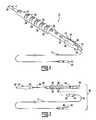
- FIG. 1is a perspective view of the monopolar stimulation probe system, according to a preferred embodiment of the present invention
- FIG. 2is an exploded view of a probe system, according to a preferred embodiment of the present invention.
- FIGS. 3A , 3 B, and 3 Cshow top, bottom, and side views of a handle for use with the present probe system, according to a preferred embodiment of the present invention
- FIG. 4is a side view of a probe wire and cable without the handle, according to a preferred embodiment of the present invention.
- FIG. 5is a detailed view of the probe wire tip, according to a preferred embodiment of the present invention.
- FIG. 6is a view of an alternative preferred embodiment of the handle shown in FIG. 3A .
- the present inventionis a monopolar stimulating probe system, generally referred to by reference number 10 .
- Probe system 10includes a wire probe 12 , a handle 14 , and a cable 16 for use with a neuro-monitoring device 100 .
- the present probe systemmay be sold in the form of a sterile kit, as will be described below.
- FIGS. 1-5illustrate the present probe system 10 in a preferred embodiment.
- Probe systemincludes wire probe 12 , handle 14 and cable 16 .
- Handle 14has a first end 22 and a second end 20 .
- First endreceives probe 14 ;
- second endreceives cable 16 .
- a channel 24is formed axially in handle 14 , along its full length from first end 22 to second end 20 .
- Channel 24has a shaped portion 18 at second end 20 to receive a cable adaptor 40 .
- a series of openings or “windows” 26are formed on the top and bottom of handle 14 to allow the user to see into channel 24 .
- Channel 24is otherwise closed radially and thus secures wire probe 12 from movement in other than the axial direction, that is, co-axial with channel 24 .
- the exterior surface of handle 14includes a set of ribs 28 that allow the user to obtain a better purchase on handle 14 and to enable the user to find a comfortable gripping position on the exterior surface.
- set of ribs 28includes a set of radial variations or bulges that are staggered with alternating bulges being offset from the long axis of handle.
- Windows 26also alternate so that a window 26 formed in a bulge at the top of handle 14 is followed axially by a window 26 at the next bulge at the bottom of handle 14 . While this exact surface configuration of handle 14 is not required, an effective surface configuration for allowing the surgeon non-slip control and, moreover, the ability to apply well-controlled axial force to handle 14 that is transmitted efficiently to wire probe 12 is critical.
- the present configurationprovides good contact with the gloved fingers of the surgeon by providing variations in diameter along the axial length of probe 12 for better, more comfortable finger grip and for the application of controlled, non-slip, axial force.
- the use of windows 26allows the surgeon to visually confirm that wire probe 12 is fully seated in adaptor 40 .
- Wire probe 12is a thin but rigid electrical conductor 30 , preferably made of steel, most preferably made of stainless steel, such as 316 stainless steel, with an insulating layer 32 made of a non-conductor, such as parylene C, a chemical vapor-deposited poly(p-xylylene) polymer.
- the type of wire for probe 12may be K-wire.
- K-wireis well-known in surgery such as, for example, holding bone fragments together, providing anchors for traction, and serving as guides for X-ray or fluoroscopy images.
- the length of the K-wire in the present wire probe 12will depend on the purpose for which the probe is being used; it will be cut longer for less invasive procedures, such as lumbar spine procedures and stimulating pedical screws, and shorter for more invasive ones, such as lumbar discectomies and fusions with pedical screws, and still shorter probes for stimulating pedical screws in the thoracic and cervical areas.
- Another advantage of the present probe systemis that handle 14 and cable 16 can be used with different lengths of probes 12 allowing for a kit to be developed of at least one handle 14 , at least one cable 16 and a range of probe wires 12 of different lengths.
- Wire probe 12has a sensor tip 34 at a first end (see FIG. 5 ) and an opposing, second end 36 (see FIG. 2 ).
- the insulation layer 32 toward sensor tip 34is tapered ending just short of the sensor tip 34 , and also having a short section of uninsulated conductor 30 at adaptor end 36 to for electrical contact when seated in adaptor 40 .
- Probe tip 34may be hemispherical in shape and may have a diameter of 1.6 mm, a radius of curvature of 0.8 mm. In addition, the very end of probe 12 may be slightly flattened. Other shapes for probe tip 34 are possible depending on the specific preference of the surgeon for the type of use contemplated, such as, for example, a ball tip and a tip with an angled face.
- a kit as described abovemay include probe wires with differently shaped tips, too. Insulating layer 32 ends short of second end 36 and may have approximately 11.25 mm free of insulation at 30 . Overall wire probe 12 may be 10-35 cm long.
- Cable 16has an adaptor 40 on first end 44 and a connector 48 at a second, opposing end 50 ; connector 42 may be identical to adaptor 40 .
- Another advantage of the present cable 16is that either first or second ends 44 , 50 , respectively, may be plugged into a neuro-monitoring device and the remaining end inserted into handle 14 .
- the exterior shape of adaptor 40 (or connector 50 ), having enlarged portions,is the same shape as shaped portion 18 of channel 20 so that adaptor 40 fits snuggly into shaped portion 18 and handle 14 holds adaptor 40 securely in place axially, allowing no movement in the axial direction.
- Adaptor 40is inserted from the side of handle 14 because the forces on adaptor, as transmitted from wire probe 12 are axial, and the shape of shaped portion 18 will prevent axial movement but, despite the axial resistance to movement, adaptor 40 is nonetheless easily inserted and removed in the radial direction, that is, from the side.
- FIGS. 1 and 2illustrate the assembly of probe system 10 .
- handle 14is shown with adaptor 40 pressed into channel 24 at second end 20 of handle 14 leaving conductor 44 running therefrom to a source of electrical current and a neuro-monitoring device (not shown).
- FIG. 2illustrates the second end 36 of wire probe 12 near first end 22 of handle 14 , with wire probe 12 being positioned near channel 24 beginning at first end 22 of handle 14 with second end 36 of wire probe 12 being visible through one of the windows 26 in FIG. 1 .
- FIG. 1illustrates wire conductor 30 fully seated in adaptor 40 and held in place by handle 14 , ready for use in surgery.
- probe system 10can be used to temporarily position wire probe 12 within the body, then used to identify neural tissue proximate to sensor tip 34 , and then handle 14 can be removed while wire probe 12 remains positioned in the body.
- Wire probe 12can guide a dilator or other surgical instrument as the surgeon slides the dilator or other device overtop or along wire probe 12 .
- cable 16can be reconnected to wire probe 14 either by inserting proximal end of wire probe 12 directly into adaptor 40 or alternatively via handle 14 , and then resuming stimulation in a continuous or intermittent manner.
- handle 14 ′includes a flat terminal 70 for use by a surgeon to tap probe wire 12 into the patient's body.
- Flat terminal 70is preferably integrally formed as part of said second end 20 of handle 14 ′ and is approximately 2 centimeters in diameter.
Landscapes
- Health & Medical Sciences (AREA)
- Life Sciences & Earth Sciences (AREA)
- Heart & Thoracic Surgery (AREA)
- Neurology (AREA)
- Veterinary Medicine (AREA)
- Public Health (AREA)
- Engineering & Computer Science (AREA)
- Biomedical Technology (AREA)
- General Health & Medical Sciences (AREA)
- Animal Behavior & Ethology (AREA)
- Nuclear Medicine, Radiotherapy & Molecular Imaging (AREA)
- Radiology & Medical Imaging (AREA)
- Neurosurgery (AREA)
- Cardiology (AREA)
- Psychology (AREA)
- Orthopedic Medicine & Surgery (AREA)
- Physics & Mathematics (AREA)
- Biophysics (AREA)
- Pathology (AREA)
- Medical Informatics (AREA)
- Molecular Biology (AREA)
- Surgery (AREA)
- Surgical Instruments (AREA)
Abstract
Description
Claims (18)
Priority Applications (1)
| Application Number | Priority Date | Filing Date | Title |
|---|---|---|---|
| US12/547,852US8137285B1 (en) | 2008-08-26 | 2009-08-26 | Monopolar stimulation probe system |
Applications Claiming Priority (2)
| Application Number | Priority Date | Filing Date | Title |
|---|---|---|---|
| US9183108P | 2008-08-26 | 2008-08-26 | |
| US12/547,852US8137285B1 (en) | 2008-08-26 | 2009-08-26 | Monopolar stimulation probe system |
Publications (1)
| Publication Number | Publication Date |
|---|---|
| US8137285B1true US8137285B1 (en) | 2012-03-20 |
Family
ID=45813292
Family Applications (1)
| Application Number | Title | Priority Date | Filing Date |
|---|---|---|---|
| US12/547,852Active2029-11-29US8137285B1 (en) | 2008-08-26 | 2009-08-26 | Monopolar stimulation probe system |
Country Status (1)
| Country | Link |
|---|---|
| US (1) | US8137285B1 (en) |
Cited By (7)
| Publication number | Priority date | Publication date | Assignee | Title |
|---|---|---|---|---|
| US20110308348A1 (en)* | 2010-06-21 | 2011-12-22 | Jtekt Corporation | Steering system and coupling wire |
| US20130289439A1 (en)* | 2012-04-25 | 2013-10-31 | Medtronic Xomed, Inc. | Stimulation probe for robotic and laparoscopic surgery |
| US20160310042A1 (en)* | 2015-04-22 | 2016-10-27 | Acclarent, Inc. | System and method to map structures of nasal cavity |
| CN106618566A (en)* | 2015-11-03 | 2017-05-10 | 中国科学院遗传与发育生物学研究所 | Method for positioning scar tissue of chronic spinal cord injury |
| US20170157389A1 (en)* | 2011-01-21 | 2017-06-08 | California Institute Of Technology | Parylene-based microelectrode array implant for spinal cord stimulation |
| CN110622259A (en)* | 2017-02-28 | 2019-12-27 | 克瑞嘉纳无限公司 | Probe assembly having cable assembly including wire pairs |
| US11134987B2 (en) | 2011-10-27 | 2021-10-05 | DePuy Synthes Products, Inc. | Method and devices for a sub-splenius/supra-levator scapulae surgical access technique |
Citations (17)
| Publication number | Priority date | Publication date | Assignee | Title |
|---|---|---|---|---|
| US5042482A (en)* | 1989-02-14 | 1991-08-27 | Medelec, Inc. | Disposable monopolar needle assembly |
| US5885219A (en) | 1996-01-16 | 1999-03-23 | Nightengale; Christopher | Interrogation device and method |
| US6533732B1 (en)* | 2000-10-17 | 2003-03-18 | William F. Urmey | Nerve stimulator needle guidance system |
| US6618626B2 (en) | 2001-01-16 | 2003-09-09 | Hs West Investments, Llc | Apparatus and methods for protecting the axillary nerve during thermal capsullorhaphy |
| US20050070895A1 (en)* | 2003-09-30 | 2005-03-31 | Thomas Ryan | Electrosurgical instrument and method for transecting an organ |
| US20050075578A1 (en) | 2001-09-25 | 2005-04-07 | James Gharib | System and methods for performing surgical procedures and assessments |
| US6925333B2 (en) | 2001-05-22 | 2005-08-02 | Peter Krebs | Combination needle for peripheral nerve block |
| US20050182454A1 (en) | 2001-07-11 | 2005-08-18 | Nuvasive, Inc. | System and methods for determining nerve proximity, direction, and pathology during surgery |
| US20060025702A1 (en)* | 2004-07-29 | 2006-02-02 | Medtronic Xomed, Inc. | Stimulator handpiece for an evoked potential monitoring system |
| US20070021682A1 (en)* | 2005-07-20 | 2007-01-25 | Nuvasive Inc. | System and methods for performing neurophysiologic assessments with pressure monitoring |
| US7206641B2 (en) | 2003-07-23 | 2007-04-17 | University Hospitals Of Cleveland | Mapping probe system for neuromuscular electrical stimulation apparatus |
| US7207949B2 (en) | 2003-09-25 | 2007-04-24 | Nuvasive, Inc. | Surgical access system and related methods |
| US20070179508A1 (en)* | 2005-12-12 | 2007-08-02 | Cook Critical Care Incorporated | Hyperechoic stimulating block needle |
| US7282033B2 (en) | 2002-09-04 | 2007-10-16 | Urmey William F | Positioning system for a nerve stimulator needle |
| US7462162B2 (en) | 2001-09-04 | 2008-12-09 | Broncus Technologies, Inc. | Antiproliferative devices for maintaining patency of surgically created channels in a body organ |
| US20090018610A1 (en) | 2004-10-07 | 2009-01-15 | James Gharib | System and methods for assessing the neuromuscular pathway prior to nerve testing |
| US7553307B2 (en) | 2004-10-15 | 2009-06-30 | Baxano, Inc. | Devices and methods for tissue modification |
- 2009
- 2009-08-26USUS12/547,852patent/US8137285B1/enactiveActive
Patent Citations (19)
| Publication number | Priority date | Publication date | Assignee | Title |
|---|---|---|---|---|
| US5042482A (en)* | 1989-02-14 | 1991-08-27 | Medelec, Inc. | Disposable monopolar needle assembly |
| US5885219A (en) | 1996-01-16 | 1999-03-23 | Nightengale; Christopher | Interrogation device and method |
| US6533732B1 (en)* | 2000-10-17 | 2003-03-18 | William F. Urmey | Nerve stimulator needle guidance system |
| US6618626B2 (en) | 2001-01-16 | 2003-09-09 | Hs West Investments, Llc | Apparatus and methods for protecting the axillary nerve during thermal capsullorhaphy |
| US6925333B2 (en) | 2001-05-22 | 2005-08-02 | Peter Krebs | Combination needle for peripheral nerve block |
| US20050182454A1 (en) | 2001-07-11 | 2005-08-18 | Nuvasive, Inc. | System and methods for determining nerve proximity, direction, and pathology during surgery |
| US7462162B2 (en) | 2001-09-04 | 2008-12-09 | Broncus Technologies, Inc. | Antiproliferative devices for maintaining patency of surgically created channels in a body organ |
| US20050075578A1 (en) | 2001-09-25 | 2005-04-07 | James Gharib | System and methods for performing surgical procedures and assessments |
| US20090192403A1 (en) | 2001-09-25 | 2009-07-30 | Nuvasive, Inc. | System And Methods For Performing Surgical Procedures and Assessments |
| US7522953B2 (en) | 2001-09-25 | 2009-04-21 | Nuvasive, Inc. | System and methods for performing surgical procedures and assessments |
| US7282033B2 (en) | 2002-09-04 | 2007-10-16 | Urmey William F | Positioning system for a nerve stimulator needle |
| US7206641B2 (en) | 2003-07-23 | 2007-04-17 | University Hospitals Of Cleveland | Mapping probe system for neuromuscular electrical stimulation apparatus |
| US7207949B2 (en) | 2003-09-25 | 2007-04-24 | Nuvasive, Inc. | Surgical access system and related methods |
| US20050070895A1 (en)* | 2003-09-30 | 2005-03-31 | Thomas Ryan | Electrosurgical instrument and method for transecting an organ |
| US20060025702A1 (en)* | 2004-07-29 | 2006-02-02 | Medtronic Xomed, Inc. | Stimulator handpiece for an evoked potential monitoring system |
| US20090018610A1 (en) | 2004-10-07 | 2009-01-15 | James Gharib | System and methods for assessing the neuromuscular pathway prior to nerve testing |
| US7553307B2 (en) | 2004-10-15 | 2009-06-30 | Baxano, Inc. | Devices and methods for tissue modification |
| US20070021682A1 (en)* | 2005-07-20 | 2007-01-25 | Nuvasive Inc. | System and methods for performing neurophysiologic assessments with pressure monitoring |
| US20070179508A1 (en)* | 2005-12-12 | 2007-08-02 | Cook Critical Care Incorporated | Hyperechoic stimulating block needle |
Cited By (17)
| Publication number | Priority date | Publication date | Assignee | Title |
|---|---|---|---|---|
| US9016160B2 (en)* | 2010-06-21 | 2015-04-28 | Jtekt Corporation | Steering system and coupling wire |
| US20110308348A1 (en)* | 2010-06-21 | 2011-12-22 | Jtekt Corporation | Steering system and coupling wire |
| US20170157389A1 (en)* | 2011-01-21 | 2017-06-08 | California Institute Of Technology | Parylene-based microelectrode array implant for spinal cord stimulation |
| US11911017B2 (en)* | 2011-10-27 | 2024-02-27 | DePuy Synthes Products, Inc. | Method and devices for a sub-splenius/supra-levator scapulae surgical access technique |
| US11278323B2 (en) | 2011-10-27 | 2022-03-22 | DePuy Synthes Products, Inc. | Method and devices for a sub-splenius/supra-levator scapulae surgical access technique |
| US11241255B2 (en) | 2011-10-27 | 2022-02-08 | DePuy Synthes Products, Inc. | Method and devices for a sub-splenius/supra-levator scapulae surgical access technique |
| US11234736B2 (en) | 2011-10-27 | 2022-02-01 | DePuy Synthes Products, Inc. | Method and devices for a sub-splenius/supra-levator scapulae surgical access technique |
| US11134987B2 (en) | 2011-10-27 | 2021-10-05 | DePuy Synthes Products, Inc. | Method and devices for a sub-splenius/supra-levator scapulae surgical access technique |
| US11937797B2 (en) | 2011-10-27 | 2024-03-26 | DePuy Synthes Products, Inc. | Method and devices for a sub-splenius/supra-levator scapulae surgical access technique |
| US11103700B2 (en) | 2012-04-25 | 2021-08-31 | Medtronic, Inc. | Stimulation probe for robotic and laparoscopic surgery |
| AU2013251660B2 (en)* | 2012-04-25 | 2017-10-05 | Medtronic Xomed, Inc. | Stimulation probe for robotic and laparoscopic surgery |
| US20130289439A1 (en)* | 2012-04-25 | 2013-10-31 | Medtronic Xomed, Inc. | Stimulation probe for robotic and laparoscopic surgery |
| US11351369B2 (en)* | 2012-04-25 | 2022-06-07 | Medtronic Xomed, Inc. | Stimulation probe for robotic and laparoscopic surgery |
| US10362965B2 (en)* | 2015-04-22 | 2019-07-30 | Acclarent, Inc. | System and method to map structures of nasal cavity |
| US20160310042A1 (en)* | 2015-04-22 | 2016-10-27 | Acclarent, Inc. | System and method to map structures of nasal cavity |
| CN106618566A (en)* | 2015-11-03 | 2017-05-10 | 中国科学院遗传与发育生物学研究所 | Method for positioning scar tissue of chronic spinal cord injury |
| CN110622259A (en)* | 2017-02-28 | 2019-12-27 | 克瑞嘉纳无限公司 | Probe assembly having cable assembly including wire pairs |
Similar Documents
| Publication | Publication Date | Title |
|---|---|---|
| US8137285B1 (en) | Monopolar stimulation probe system | |
| US10695108B1 (en) | Neurophysiological apparatus and procedures | |
| US8255044B2 (en) | System and methods for performing dynamic pedicle integrity assessments | |
| US7942826B1 (en) | Insulated pedicle access system and related methods | |
| US11337630B2 (en) | Directional dilator for intraoperative monitoring | |
| EP1848359B1 (en) | Electrically insulated surgical needle assembly | |
| US20130184551A1 (en) | Neuromonitoring dilator | |
| US8103339B2 (en) | Nerve stimulator with suction capability | |
| US11819254B2 (en) | Stimulating targeting needle | |
| AU2002353954A1 (en) | System and methods for performing percutaneous pedicle integrity assessments | |
| KR20130129406A (en) | Handheld emg stimulator device with adjustable shaft length | |
| WO2003037170A2 (en) | System and methods for performing percutaneous pedicle integrity assessments | |
| JP2023508529A (en) | Neurosurgical guidewire with integrated connector for sensing and applying therapeutic electrical energy | |
| US20170238788A1 (en) | Illuminated Endoscopic Pedicle Probe With Dynamic Real Time Monitoring For Proximity To Nerves | |
| EP3349639A1 (en) | Illuminated endoscopic pedicle probe with dynamic real time monitoring for proximity to nerves | |
| US20190380844A1 (en) | Surgical probe device | |
| WO2024062362A1 (en) | Device for neurophysiological analysis in the field of neurosurgical endoscopy and endoscopic group including the device and an endoscope |
Legal Events
| Date | Code | Title | Description |
|---|---|---|---|
| AS | Assignment | Owner name:RHYTHMLINK INTERNATIONAL, LLC, SOUTH CAROLINA Free format text:ASSIGNMENT OF ASSIGNORS INTEREST;ASSIGNORS:REGAN, SHAWN V.;SMITH, ISIAH D.;MEWBORNE, JAMES M.;AND OTHERS;REEL/FRAME:027674/0922 Effective date:20080826 | |
| STCF | Information on status: patent grant | Free format text:PATENTED CASE | |
| FPAY | Fee payment | Year of fee payment:4 | |
| AS | Assignment | Owner name:MADISON CAPITAL FUNDING LLC, AS AGENT, ILLINOIS Free format text:SECURITY INTEREST;ASSIGNOR:RHYTHMLINK INTERNATIONAL, LLC;REEL/FRAME:048380/0881 Effective date:20190219 | |
| MAFP | Maintenance fee payment | Free format text:PAYMENT OF MAINTENANCE FEE, 8TH YR, SMALL ENTITY (ORIGINAL EVENT CODE: M2552); ENTITY STATUS OF PATENT OWNER: SMALL ENTITY Year of fee payment:8 | |
| FEPP | Fee payment procedure | Free format text:ENTITY STATUS SET TO UNDISCOUNTED (ORIGINAL EVENT CODE: BIG.); ENTITY STATUS OF PATENT OWNER: LARGE ENTITY | |
| AS | Assignment | Owner name:APOGEM CAPITAL LLC, AS ADMINISTRATIVE AGENT, ILLINOIS Free format text:SECURITY INTEREST;ASSIGNOR:MADISON CAPITAL FUNDING LLC, AS ADMINISTRATIVE AGENT;REEL/FRAME:059563/0359 Effective date:20220401 | |
| AS | Assignment | Owner name:APOGEM CAPITAL LLC, AGENT, ILLINOIS Free format text:SECURITY INTEREST;ASSIGNOR:RHYTHMLINK INTERNATIONAL, LLC;REEL/FRAME:062985/0933 Effective date:20230315 Owner name:RHYTHMLINK INTERNATIONAL, LLC, SOUTH CAROLINA Free format text:RELEASE BY SECURED PARTY;ASSIGNOR:APOGEM CAPITAL FUNDING LLC, AS SUCCESSOR AGENT;REEL/FRAME:062995/0706 Effective date:20230315 | |
| MAFP | Maintenance fee payment | Free format text:PAYMENT OF MAINTENANCE FEE, 12TH YEAR, LARGE ENTITY (ORIGINAL EVENT CODE: M1553); ENTITY STATUS OF PATENT OWNER: LARGE ENTITY Year of fee payment:12 |