US8137082B2 - Air blower assembly - Google Patents
Air blower assemblyDownload PDFInfo
- Publication number
- US8137082B2 US8137082B2US11/961,888US96188807AUS8137082B2US 8137082 B2US8137082 B2US 8137082B2US 96188807 AUS96188807 AUS 96188807AUS 8137082 B2US8137082 B2US 8137082B2
- Authority
- US
- United States
- Prior art keywords
- housing
- motor
- blower
- sealing gasket
- inwardly facing
- Prior art date
- Legal status (The legal status is an assumption and is not a legal conclusion. Google has not performed a legal analysis and makes no representation as to the accuracy of the status listed.)
- Active, expires
Links
- 238000007789sealingMethods0.000claimsdescription22
- 239000006260foamSubstances0.000claimsdescription9
- 238000001914filtrationMethods0.000claimsdescription3
- 238000009413insulationMethods0.000claimsdescription3
- 230000013011matingEffects0.000claimsdescription3
- 239000013536elastomeric materialSubstances0.000claims2
- 238000010438heat treatmentMethods0.000description2
- 239000000463materialSubstances0.000description2
- 238000003287bathingMethods0.000description1
- 230000001419dependent effectEffects0.000description1
- 229920001971elastomerPolymers0.000description1
- 239000000806elastomerSubstances0.000description1
- 238000009434installationMethods0.000description1
- 238000012986modificationMethods0.000description1
- 230000004048modificationEffects0.000description1
- 238000010926purgeMethods0.000description1
Images


Classifications
- F—MECHANICAL ENGINEERING; LIGHTING; HEATING; WEAPONS; BLASTING
- F04—POSITIVE - DISPLACEMENT MACHINES FOR LIQUIDS; PUMPS FOR LIQUIDS OR ELASTIC FLUIDS
- F04D—NON-POSITIVE-DISPLACEMENT PUMPS
- F04D29/00—Details, component parts, or accessories
- F04D29/60—Mounting; Assembling; Disassembling
- F04D29/62—Mounting; Assembling; Disassembling of radial or helico-centrifugal pumps
- F04D29/624—Mounting; Assembling; Disassembling of radial or helico-centrifugal pumps especially adapted for elastic fluid pumps
- F—MECHANICAL ENGINEERING; LIGHTING; HEATING; WEAPONS; BLASTING
- F04—POSITIVE - DISPLACEMENT MACHINES FOR LIQUIDS; PUMPS FOR LIQUIDS OR ELASTIC FLUIDS
- F04D—NON-POSITIVE-DISPLACEMENT PUMPS
- F04D29/00—Details, component parts, or accessories
- F04D29/40—Casings; Connections of working fluid
- F04D29/42—Casings; Connections of working fluid for radial or helico-centrifugal pumps
- F04D29/4206—Casings; Connections of working fluid for radial or helico-centrifugal pumps especially adapted for elastic fluid pumps
- F04D29/4226—Fan casings
- F—MECHANICAL ENGINEERING; LIGHTING; HEATING; WEAPONS; BLASTING
- F04—POSITIVE - DISPLACEMENT MACHINES FOR LIQUIDS; PUMPS FOR LIQUIDS OR ELASTIC FLUIDS
- F04D—NON-POSITIVE-DISPLACEMENT PUMPS
- F04D29/00—Details, component parts, or accessories
- F04D29/60—Mounting; Assembling; Disassembling
- F04D29/62—Mounting; Assembling; Disassembling of radial or helico-centrifugal pumps
- F04D29/624—Mounting; Assembling; Disassembling of radial or helico-centrifugal pumps especially adapted for elastic fluid pumps
- F04D29/626—Mounting or removal of fans
Definitions
- Air blowersare used in various applications, including for example bathing installations, such as whirlpool baths and spas.
- the air blower assembly disclosed hereinis particularly suited to such applications, although it is to be understood that the air blower assembly may have utility in many other applications.
- FIG. 1is an isometric view of an exemplary embodiment of an air blower.
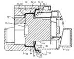
- FIGS. 2A and 2Bare cross-sectional views illustrating features of an air blower.
- FIG. 3is an isometric exploded view of the air blower of FIG. 1 .
- FIGS. 4A and 4Bare isometric views of first and second housing structures of the air blower.
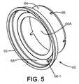
- FIG. 5is an isometric view of a sealing gasket.
- FIGS. 6A and 6Bare isometric front side and back side views of an exemplary embodiment of a motor and impeller assembly.
- FIGS. 1-6BAn exemplary embodiment of an air blower 50 is illustrated in FIGS. 1-6B .
- the blowerincludes first and second housing structures 52 and 54 , which are configured to support and house a blower motor assembly 70 , which may include an electric motor with a shaft, and an impeller fan mounted on or driven by the motor.
- the housing structuresare secured together, along with a sealing gasket 60 , in an assembled condition by threaded fasteners 56 .
- the sealing gasket 60includes a flange portion 62 which is captured between mating interlocking surfaces of the two housing structures.
- FIG. 3depicts parts of an exemplary embodiment of an air blower 50 .
- the blowerincludes a first cover 84 and foam member 80 .
- the foam member 80is fitted against the exterior of the housing structure 52 to provide sound insulation and dirt filtration, and a cover 84 is attached to the first housing structure over the foam member 80 .
- the blower 50may also include an intake foam member 82 which is positioned inside the second housing structure 54 , so that the end surface 70 - 4 of the motor housing 70 - 1 is positioned against the intake foam member.
- the foam member 82may provide sound insulation and dirt filtration functions in an exemplary embodiment.
- One or both of the foam members 80 and 82may be omitted in some embodiments.
- a second cover 86is attached to the second housing structure 54 .
- An electrical power supply wiring 88is passed through a rear cover 86 ( FIG. 3 ) to the motor assembly 70 to provide a source of electrical power for the motor.
- the motor assemblyis secured in position within the housing structures 52 and 54 by the cooperative engagement of internal rib surfaces of the housing structures and the gasket, without the use of separate clamps or fasteners. This simplifies the assembly of the blower and reduces a part count.
- the gasket 60may be fabricated of a flexible material such as flexible PVC or other suitable elastomer.
- the housing structures 52 and 54may be fabricated from a rigid plastic material in one exemplary embodiment.
- the gasket 60in an exemplary embodiment defines a central opening 60 A and a tubular gasket portion 64 which are sized to receive in a tight fit the housing portion 70 - 1 of the motor assembly.
- the tubular gasket portion 64extends into the second housing structure 54 , into which the motor assembly 70 is fitted.
- the tubular portion 64may have a longitudinal length sufficient to extend past the motor housing portion 70 - 1 and has slots 66 formed therein.
- the motor assembly 70in an exemplary embodiment includes an electric motor 70 - 2 which drives an impeller 70 - 3 inside the housing portion 70 - 1 ( FIGS. 6A-6B ).
- the housing portion 70 - 1has a generally cylindrical configuration, and the gasket 60 is sized in accordance with the dimensions of the housing portion cylindrical configuration.
- the housing portionmay take a different shape, and the gasket 60 may be adapted to the different shape.
- the element portion 68may be provided with slots or other openings to receive motor housing protrusions of a different motor design.
- the gasket portion 68may include an opening 68 - 1 ( FIG. 5 ) through which supply wiring 88 may be passed to the electric motor connections.
- the housing structures 52 and 54include respective interlocking flange portions which mate together with the gasket 60 in an assembled condition.
- Housing structure 52includes inner flange portion 52 - 3 and shoulder 52 - 2 ( FIG. 4A ).
- Housing structure 54includes outer flange portion 54 - 3 and edge surface 54 - 4 ( FIG. 4B ).
- the flange portion 62 of the gasket 60is captured between the inner and outer flange portions 52 - 3 and 54 - 3 , and the edge surface 54 - 4 is brought against shoulder surface 52 - 2 .
- the threaded fasteners 56draw the housing structures together and compress the flange portion 62 of the gasket in a sealed arrangement.
- housing structures 52 and 54each have inwardly facing, spaced longitudinal ribs.
- housing structure 52includes spaced ribs 52 - 1
- housing structure 54has spaced ribs 54 - 1 .
- the spaced ribs 54 - 1 on the second housing structure 54define rib surfaces 54 - 1 A configured to capture the motor housing portion 70 - 1 and gasket 60 in a radial sense in an interference fit, with the surfaces 54 - 1 A being generally oriented in a longitudinal sense, with a slight draw or taper so that interference contact of the rib surface with the housing portion 70 - 1 and gasket 60 increases as the motor housing is inserted into the housing 54 .
- the ribs 54 - 1also include shoulder features 54 - 1 B at the base of the rib surface 54 - 1 A to axially capture the motor housing portion 70 - 1 to prevent further axial movement toward the interior of the second housing structure 54 .
- the shape of the rib surfaces 54 - 1 A and 54 - 1 Bmay also be configured to contact the tubular portion of the gasket to roll the end of the gasket over the end of the motor housing ( FIG. 2B ).
- the spaced ribs 52 - 1 in the first housing structure 52are configured to contact the motor assembly 70 to prevent axial movement of the motor toward the outlet port 52 - 2 of the first housing structure 52 .
- the end surfaces 52 - 1 A of the ribs 52 - 1are configured to contact and compress the inner edge 65 of the gasket against the motor housing ( FIG. 2A ).
- the ribs 52 - 1 and 54 - 1 in the housing structuresserve to register the radial and axial positions of the motor assembly 70 inside the blower housing without the use of separate clamp fastener device, with the gasket 60 providing sealing between the two housing structures.
- the motor assembly 70is configured to draw air into port 70 - 4 of the motor assembly 70 and expel air out of the outlet port 52 - 2 .
- the first housing structure 52may be configured as a pressure side of the blower assembly with an outlet port 52 - 2 through which pressurized air is delivered by the blower assembly under operating conditions.
- the second housing structure 54may be configured as an inlet side of the blower assembly into which air is drawn by action of the motor assembly 70 .
- the particular path of the air from the inlet port 70 - 4 to the outlet port 52 - 2may be dependent on the particular design of the motor assembly 70 .
- One exemplary air flow pathis illustrated in FIG.
- a blowermay include other features, such as a circuit assembly mounted, e.g. on or adjacent to the cover 86 to control features of the blower assembly, e.g. motor speed or a blower purge cycle.
- a heater elementmay be placed in the output side of the blower assembly, e.g. a resistive heating element mounted within plenum 90 of the housing structure 52 , to provide an air heating function.
Landscapes
- Engineering & Computer Science (AREA)
- Mechanical Engineering (AREA)
- General Engineering & Computer Science (AREA)
- Structures Of Non-Positive Displacement Pumps (AREA)
Abstract
Description
Claims (12)
Priority Applications (1)
| Application Number | Priority Date | Filing Date | Title |
|---|---|---|---|
| US11/961,888US8137082B2 (en) | 2007-12-20 | 2007-12-20 | Air blower assembly |
Applications Claiming Priority (1)
| Application Number | Priority Date | Filing Date | Title |
|---|---|---|---|
| US11/961,888US8137082B2 (en) | 2007-12-20 | 2007-12-20 | Air blower assembly |
Publications (2)
| Publication Number | Publication Date |
|---|---|
| US20090162226A1 US20090162226A1 (en) | 2009-06-25 |
| US8137082B2true US8137082B2 (en) | 2012-03-20 |
Family
ID=40788865
Family Applications (1)
| Application Number | Title | Priority Date | Filing Date |
|---|---|---|---|
| US11/961,888Active2029-12-18US8137082B2 (en) | 2007-12-20 | 2007-12-20 | Air blower assembly |
Country Status (1)
| Country | Link |
|---|---|
| US (1) | US8137082B2 (en) |
Cited By (14)
| Publication number | Priority date | Publication date | Assignee | Title |
|---|---|---|---|---|
| US20140197299A1 (en)* | 2013-01-16 | 2014-07-17 | Hewlett-Packard Development Company, L.P. | Vibration isolation system |
| US10709866B2 (en) | 2014-05-13 | 2020-07-14 | Fisher & Paykel Healthcare Limited | Usability features for respiratory humidification system |
| US10828482B2 (en) | 2013-12-20 | 2020-11-10 | Fisher & Paykel Healthcare Limited | Humidification system connections |
| US10974015B2 (en) | 2012-03-15 | 2021-04-13 | Fisher & Paykel Healthcare Limited | Respiratory gas humidification system |
| US11129956B2 (en) | 2012-04-27 | 2021-09-28 | Fisher & Paykel Healthcare Limited | Usability features for respiratory humidification system |
| US11173272B2 (en) | 2014-05-02 | 2021-11-16 | Fisher & Paykel Healthcare Limited | Gas humidification arrangement |
| US11278689B2 (en) | 2014-11-17 | 2022-03-22 | Fisher & Paykel Healthcare Limited | Humidification of respiratory gases |
| US11278700B2 (en) | 2015-06-24 | 2022-03-22 | Fisher & Paykel Healthcare Limited | Breathing assistance apparatus |
| US11324911B2 (en) | 2014-06-03 | 2022-05-10 | Fisher & Paykel Healthcare Limited | Flow mixers for respiratory therapy systems |
| US11351332B2 (en) | 2016-12-07 | 2022-06-07 | Fisher & Paykel Healthcare Limited | Sensing arrangements for medical devices |
| US11511069B2 (en) | 2013-09-13 | 2022-11-29 | Fisher & Paykel Healthcare Limited | Humidification system |
| US11559653B2 (en) | 2014-02-07 | 2023-01-24 | Fisher & Paykel Healthcare Limited | Respiratory humidification system |
| US11801360B2 (en) | 2013-09-13 | 2023-10-31 | Fisher & Paykel Healthcare Limited | Connections for humidification system |
| US20230349395A1 (en)* | 2014-01-03 | 2023-11-02 | Bmc Medical Co., Ltd. | Blower device and respirator including blower device |
Families Citing this family (7)
| Publication number | Priority date | Publication date | Assignee | Title |
|---|---|---|---|---|
| US8931481B2 (en)* | 2009-06-04 | 2015-01-13 | Redmed Limited | Flow generator chassis assembly with suspension seal |
| US8616860B2 (en)* | 2010-03-08 | 2013-12-31 | Trane International Inc. | System and method for reducing compressor noise |
| FR2980538B1 (en)* | 2011-09-27 | 2013-10-25 | Thermodyn | COMPRESSOR MOTOR WITH REMOVABLE CARTRIDGE |
| JP6170947B2 (en)* | 2012-02-02 | 2017-07-26 | アイアセット アーゲー | Soundproof enclosure for ventilators |
| USD761410S1 (en)* | 2013-09-11 | 2016-07-12 | Alvimar-Global | Blower with integrated base |
| JP6801774B2 (en)* | 2017-03-21 | 2020-12-16 | 株式会社村田製作所 | Blower, fluid control device |
| US10801517B2 (en)* | 2018-11-29 | 2020-10-13 | Ming-Chih Wang | Blower housing |
Citations (19)
| Publication number | Priority date | Publication date | Assignee | Title |
|---|---|---|---|---|
| US2286993A (en)* | 1940-10-11 | 1942-06-16 | Singer Mfg Co | Field-core holding means for electric motors |
| US3992133A (en)* | 1974-03-21 | 1976-11-16 | Heilmeier And Weinlein, Fabrik Fur Oel-Hydraulik, A Kg | Pressure fluid pump |
| US4133461A (en)* | 1976-03-04 | 1979-01-09 | Aerosol Inventions And Development S.A. Aid Sa | High-reliability valve |
| US4950133A (en) | 1988-11-15 | 1990-08-21 | Alopex Industries, Inc. | Air blower assembly |
| US4964787A (en)* | 1989-04-06 | 1990-10-23 | Walbro Corporation | Electric vehicle pump isolation mount |
| US5327036A (en)* | 1993-01-19 | 1994-07-05 | General Electric Company | Snap-on fan cover for an electric motor |
| JPH07313408A (en)* | 1994-05-24 | 1995-12-05 | Tec Corp | Vacuum cleaner |
| US5533704A (en)* | 1993-09-03 | 1996-07-09 | Behr Gmbh & Co. | Holder for an electric motor, especially for a fan of a heater of air conditioner |
| US6045112A (en)* | 1997-08-20 | 2000-04-04 | Calsonic North America, Inc. | Vibration isolation system for an electric motor |
| US6155801A (en) | 1999-03-18 | 2000-12-05 | Elnar; Joseph G. | Air blower assembly for spas |
| US6386845B1 (en) | 1999-08-24 | 2002-05-14 | Paul Bedard | Air blower apparatus |
| US20030117030A1 (en)* | 2001-12-11 | 2003-06-26 | Agnes Michael Jeffrey | Brushless motor having housing enabling alignment of stator and sensor |
| US20040027011A1 (en)* | 2002-07-24 | 2004-02-12 | Bostwick Peter K. | Optimized thermal system for an electric motor |
| US20040216907A1 (en)* | 2002-09-20 | 2004-11-04 | Happ Kenneth C. | Power tool with air seal and vibration dampener |
| US20070284954A1 (en)* | 2006-06-07 | 2007-12-13 | A.O. Smith Corporation | Totally enclosed fan cooled motor |
| US20080304986A1 (en)* | 2007-06-05 | 2008-12-11 | Resmed Limited | Blower with bearing tube |
| US20090060763A1 (en)* | 2007-08-31 | 2009-03-05 | Emerson Electric Co. | Mounting Flange, Pump Having Mounting Flange and Mold for Mounting Flange |
| US20090058209A1 (en)* | 2007-08-28 | 2009-03-05 | Baranowski Richard S | Pressed in style motor attachment |
| US7550888B2 (en)* | 2006-07-31 | 2009-06-23 | Asmo Co., Ltd. | Blower motor for vehicle air conditioning system |
- 2007
- 2007-12-20USUS11/961,888patent/US8137082B2/enactiveActive
Patent Citations (19)
| Publication number | Priority date | Publication date | Assignee | Title |
|---|---|---|---|---|
| US2286993A (en)* | 1940-10-11 | 1942-06-16 | Singer Mfg Co | Field-core holding means for electric motors |
| US3992133A (en)* | 1974-03-21 | 1976-11-16 | Heilmeier And Weinlein, Fabrik Fur Oel-Hydraulik, A Kg | Pressure fluid pump |
| US4133461A (en)* | 1976-03-04 | 1979-01-09 | Aerosol Inventions And Development S.A. Aid Sa | High-reliability valve |
| US4950133A (en) | 1988-11-15 | 1990-08-21 | Alopex Industries, Inc. | Air blower assembly |
| US4964787A (en)* | 1989-04-06 | 1990-10-23 | Walbro Corporation | Electric vehicle pump isolation mount |
| US5327036A (en)* | 1993-01-19 | 1994-07-05 | General Electric Company | Snap-on fan cover for an electric motor |
| US5533704A (en)* | 1993-09-03 | 1996-07-09 | Behr Gmbh & Co. | Holder for an electric motor, especially for a fan of a heater of air conditioner |
| JPH07313408A (en)* | 1994-05-24 | 1995-12-05 | Tec Corp | Vacuum cleaner |
| US6045112A (en)* | 1997-08-20 | 2000-04-04 | Calsonic North America, Inc. | Vibration isolation system for an electric motor |
| US6155801A (en) | 1999-03-18 | 2000-12-05 | Elnar; Joseph G. | Air blower assembly for spas |
| US6386845B1 (en) | 1999-08-24 | 2002-05-14 | Paul Bedard | Air blower apparatus |
| US20030117030A1 (en)* | 2001-12-11 | 2003-06-26 | Agnes Michael Jeffrey | Brushless motor having housing enabling alignment of stator and sensor |
| US20040027011A1 (en)* | 2002-07-24 | 2004-02-12 | Bostwick Peter K. | Optimized thermal system for an electric motor |
| US20040216907A1 (en)* | 2002-09-20 | 2004-11-04 | Happ Kenneth C. | Power tool with air seal and vibration dampener |
| US20070284954A1 (en)* | 2006-06-07 | 2007-12-13 | A.O. Smith Corporation | Totally enclosed fan cooled motor |
| US7550888B2 (en)* | 2006-07-31 | 2009-06-23 | Asmo Co., Ltd. | Blower motor for vehicle air conditioning system |
| US20080304986A1 (en)* | 2007-06-05 | 2008-12-11 | Resmed Limited | Blower with bearing tube |
| US20090058209A1 (en)* | 2007-08-28 | 2009-03-05 | Baranowski Richard S | Pressed in style motor attachment |
| US20090060763A1 (en)* | 2007-08-31 | 2009-03-05 | Emerson Electric Co. | Mounting Flange, Pump Having Mounting Flange and Mold for Mounting Flange |
Cited By (23)
| Publication number | Priority date | Publication date | Assignee | Title |
|---|---|---|---|---|
| US12350436B2 (en) | 2012-03-15 | 2025-07-08 | Fisher & Paykel Healthcare Limited | Respiratory gas humidification system |
| US10974015B2 (en) | 2012-03-15 | 2021-04-13 | Fisher & Paykel Healthcare Limited | Respiratory gas humidification system |
| US11129956B2 (en) | 2012-04-27 | 2021-09-28 | Fisher & Paykel Healthcare Limited | Usability features for respiratory humidification system |
| US11878093B2 (en) | 2012-04-27 | 2024-01-23 | Fisher & Paykel Healthcare Limited | Usability features for respiratory humidification system |
| US9347509B2 (en)* | 2013-01-16 | 2016-05-24 | Hewlett-Packard Development Company, L.P. | Vibration isolation system |
| US20140197299A1 (en)* | 2013-01-16 | 2014-07-17 | Hewlett-Packard Development Company, L.P. | Vibration isolation system |
| US11511069B2 (en) | 2013-09-13 | 2022-11-29 | Fisher & Paykel Healthcare Limited | Humidification system |
| US12053589B2 (en) | 2013-09-13 | 2024-08-06 | Fisher & Paykel Healthcare Limited | Humidification system |
| US11801360B2 (en) | 2013-09-13 | 2023-10-31 | Fisher & Paykel Healthcare Limited | Connections for humidification system |
| US10828482B2 (en) | 2013-12-20 | 2020-11-10 | Fisher & Paykel Healthcare Limited | Humidification system connections |
| US11826538B2 (en) | 2013-12-20 | 2023-11-28 | Fisher & Paykel Healthcare Limited | Humidification system connections |
| US20230349395A1 (en)* | 2014-01-03 | 2023-11-02 | Bmc Medical Co., Ltd. | Blower device and respirator including blower device |
| US12247585B2 (en)* | 2014-01-03 | 2025-03-11 | Bmc Medical Co., Ltd. | Blower device and respirator including blower device |
| US11559653B2 (en) | 2014-02-07 | 2023-01-24 | Fisher & Paykel Healthcare Limited | Respiratory humidification system |
| US12397127B2 (en) | 2014-02-07 | 2025-08-26 | Fisher & Paykel Healthcare Limited | Respiratory humidification system |
| US11173272B2 (en) | 2014-05-02 | 2021-11-16 | Fisher & Paykel Healthcare Limited | Gas humidification arrangement |
| US11992622B2 (en) | 2014-05-13 | 2024-05-28 | Fisher & Paykel Healthcare Limited | Usability features for respiratory humidification system |
| US10709866B2 (en) | 2014-05-13 | 2020-07-14 | Fisher & Paykel Healthcare Limited | Usability features for respiratory humidification system |
| US11712536B2 (en) | 2014-06-03 | 2023-08-01 | Fisher & Paykel Healthcare Limited | Flow mixers for respiratory therapy systems |
| US11324911B2 (en) | 2014-06-03 | 2022-05-10 | Fisher & Paykel Healthcare Limited | Flow mixers for respiratory therapy systems |
| US11278689B2 (en) | 2014-11-17 | 2022-03-22 | Fisher & Paykel Healthcare Limited | Humidification of respiratory gases |
| US11278700B2 (en) | 2015-06-24 | 2022-03-22 | Fisher & Paykel Healthcare Limited | Breathing assistance apparatus |
| US11351332B2 (en) | 2016-12-07 | 2022-06-07 | Fisher & Paykel Healthcare Limited | Sensing arrangements for medical devices |
Also Published As
| Publication number | Publication date |
|---|---|
| US20090162226A1 (en) | 2009-06-25 |
Similar Documents
| Publication | Publication Date | Title |
|---|---|---|
| US8137082B2 (en) | Air blower assembly | |
| US6386845B1 (en) | Air blower apparatus | |
| CN106901482B (en) | Motor mounts | |
| CN101754615B (en) | Casing assembly part of household electrical appliance and air purifier with same | |
| EP2817518B1 (en) | Sound-proofing housing for a respirator | |
| US6717299B2 (en) | Isolation system for a motor | |
| KR20160052721A (en) | Hand held appliance | |
| ITMI20051327A1 (en) | ELECTRIC FAN FOR USE ON VEHICLES | |
| US5404874A (en) | Device for connecting a fan to a face mask filter | |
| EP1842473A3 (en) | Electric motor housing for a vacuum cleaner fan assembly | |
| KR970073500A (en) | Sound absorbing room for vacuum cleaner | |
| CN114711528B (en) | hair dryer | |
| CN216089312U (en) | Hairdryer seal assembly and hairdryer | |
| US8277175B2 (en) | Combustion air supply blower with access cover and motor and fan assembly | |
| CN221511781U (en) | Control unit of cleaning device and cleaning device | |
| JP2001336795A (en) | Ventilation equipment | |
| CN217243026U (en) | hair dryer | |
| CN218103756U (en) | Electric control box assembly, electric control assembly and air treatment device | |
| KR20140061596A (en) | Opens and shuts device of air duct | |
| CN111194984B (en) | Electric hair drier | |
| CN210568965U (en) | Water pump mounting structure, thermantidote | |
| CN106322725A (en) | Filter screen device and air conditioning equipment | |
| JP5848751B2 (en) | Pump with air vent port | |
| CN221807949U (en) | Cleaning device and cleaning equipment | |
| CN220157329U (en) | Pet water blower |
Legal Events
| Date | Code | Title | Description |
|---|---|---|---|
| AS | Assignment | Owner name:G-G DISTRIBUTION AND DEVELOPMENT CO., INC.,CALIFOR Free format text:ASSIGNMENT OF ASSIGNORS INTEREST;ASSIGNOR:CAMPBELL, GRAHAM J.;REEL/FRAME:020421/0578 Effective date:20080121 Owner name:G-G DISTRIBUTION AND DEVELOPMENT CO., INC., CALIFO Free format text:ASSIGNMENT OF ASSIGNORS INTEREST;ASSIGNOR:CAMPBELL, GRAHAM J.;REEL/FRAME:020421/0578 Effective date:20080121 | |
| AS | Assignment | Owner name:PNC BANK, NATIONAL ASSOCIATION, PENNSYLVANIA Free format text:SECURITY AGREEMENT;ASSIGNORS:BALBOA WATER GROUP, INC.;BALBOA INSTRUMENTS, INC.;G-G DISTRIBUTION AND DEVELOPMENT CO., INC.;REEL/FRAME:023538/0406 Effective date:20091105 Owner name:PNC BANK, NATIONAL ASSOCIATION,PENNSYLVANIA Free format text:SECURITY AGREEMENT;ASSIGNORS:BALBOA WATER GROUP, INC.;BALBOA INSTRUMENTS, INC.;G-G DISTRIBUTION AND DEVELOPMENT CO., INC.;REEL/FRAME:023538/0406 Effective date:20091105 | |
| STCF | Information on status: patent grant | Free format text:PATENTED CASE | |
| AS | Assignment | Owner name:PNC BANK, NATIONAL ASSOCIATION, PENNSYLVANIA Free format text:SECURITY AGREEMENT;ASSIGNORS:BALBOA WATER GROUP, LLC;BALBOA INSTRUMENTS, INC.;G-G DISTRIBUTION AND DEVELOPMENT CO., INC.;REEL/FRAME:030955/0130 Effective date:20130731 | |
| AS | Assignment | Owner name:BALBOA WATER GROUP, INC., CALIFORNIA Free format text:ASSIGNMENT OF ASSIGNORS INTEREST;ASSIGNOR:G-G DISTRIBUTION AND DEVELOPMENT CO., INC.;REEL/FRAME:030963/0703 Effective date:20130731 | |
| FPAY | Fee payment | Year of fee payment:4 | |
| MAFP | Maintenance fee payment | Free format text:PAYMENT OF MAINTENANCE FEE, 8TH YEAR, LARGE ENTITY (ORIGINAL EVENT CODE: M1552); ENTITY STATUS OF PATENT OWNER: LARGE ENTITY Year of fee payment:8 | |
| AS | Assignment | Owner name:BMO HARRIS BANK N.A., AS ADMINISTRATIVE AGENT, ILLINOIS Free format text:PATENT SECURITY AGREEMENT;ASSIGNOR:BALBOA WATER GROUP, LLC;REEL/FRAME:051906/0375 Effective date:20151117 | |
| AS | Assignment | Owner name:BALBOA WATER GROUP, LLC, CALIFORNIA Free format text:ENTITY CONVERSION;ASSIGNOR:BALBOA WATER GROUP, INC.;REEL/FRAME:052150/0661 Effective date:20130731 | |
| AS | Assignment | Owner name:G-G DISTRIBUTION AND DEVELOPMENT CO., INC., CALIFORNIA Free format text:RELEASE BY SECURED PARTY;ASSIGNOR:PNC BANK, NATIONAL ASSOCIATION;REEL/FRAME:052918/0717 Effective date:20151117 Owner name:BALBOA WATER GROUP, LLC, CALIFORNIA Free format text:RELEASE BY SECURED PARTY;ASSIGNOR:PNC BANK, NATIONAL ASSOCIATION;REEL/FRAME:052918/0717 Effective date:20151117 Owner name:BALBOA WATER GROUP, INC., CALIFORNIA Free format text:RELEASE BY SECURED PARTY;ASSIGNOR:PNC BANK, NATIONAL ASSOCIATION;REEL/FRAME:052918/0717 Effective date:20151117 Owner name:BALBOA INSTRUMENTS, INC., CALIFORNIA Free format text:RELEASE BY SECURED PARTY;ASSIGNOR:PNC BANK, NATIONAL ASSOCIATION;REEL/FRAME:052918/0717 Effective date:20151117 Owner name:SPA & BATH HOLDINGS, INC., CALIFORNIA Free format text:RELEASE BY SECURED PARTY;ASSIGNOR:PNC BANK, NATIONAL ASSOCIATION;REEL/FRAME:052918/0717 Effective date:20151117 | |
| AS | Assignment | Owner name:PNC BANK, NATIONAL ASSOCIATION, AS ADMINISTRATIVE AGENT, PENNSYLVANIA Free format text:NOTICE OF GRANT OF SECURITY INTEREST IN PATENTS;ASSIGNOR:BALBOA WATER GROUP, LLC;REEL/FRAME:054341/0169 Effective date:20201028 Owner name:BALBOA WATER GROUP, LLC, CALIFORNIA Free format text:RELEASE BY SECURED PARTY;ASSIGNOR:BMO HARRIS BANK, N.A.;REEL/FRAME:054344/0627 Effective date:20201106 | |
| AS | Assignment | Owner name:BALBOA WATER GROUP, LLC, CALIFORNIA Free format text:CORRECTIVE ASSIGNMENT TO CORRECT THE PROPERTY NUMBER 8191183 PREVIOUSLY RECORDED AT REEL: 054344 FRAME: 0637. ASSIGNOR(S) HEREBY CONFIRMS THE RELEASE OF SECURITY INTEREST;ASSIGNOR:BMO HARRIS BANK, N.A.;REEL/FRAME:057144/0919 Effective date:20201106 | |
| MAFP | Maintenance fee payment | Free format text:PAYMENT OF MAINTENANCE FEE, 12TH YEAR, LARGE ENTITY (ORIGINAL EVENT CODE: M1553); ENTITY STATUS OF PATENT OWNER: LARGE ENTITY Year of fee payment:12 |