US8136779B2 - Mounting arrangement for a pressurized irrigation system - Google Patents
Mounting arrangement for a pressurized irrigation systemDownload PDFInfo
- Publication number
- US8136779B2 US8136779B2US12/844,257US84425710AUS8136779B2US 8136779 B2US8136779 B2US 8136779B2US 84425710 AUS84425710 AUS 84425710AUS 8136779 B2US8136779 B2US 8136779B2
- Authority
- US
- United States
- Prior art keywords
- irrigation
- mounting
- container
- mounting arrangement
- arrangement
- Prior art date
- Legal status (The legal status is an assumption and is not a legal conclusion. Google has not performed a legal analysis and makes no representation as to the accuracy of the status listed.)
- Active
Links
- 230000002262irrigationEffects0.000titleclaimsabstractdescription158
- 238000003973irrigationMethods0.000titleclaimsabstractdescription158
- 230000007246mechanismEffects0.000claimsabstractdescription15
- 239000012530fluidSubstances0.000claimsdescription19
- 238000004891communicationMethods0.000claimsdescription2
- 238000000034methodMethods0.000description15
- 230000006835compressionEffects0.000description8
- 238000007906compressionMethods0.000description8
- 230000005484gravityEffects0.000description5
- 230000004044responseEffects0.000description5
- 230000008859changeEffects0.000description4
- 238000012421spikingMethods0.000description4
- 238000001802infusionMethods0.000description3
- 230000037452primingEffects0.000description3
- 230000000717retained effectEffects0.000description3
- 238000001356surgical procedureMethods0.000description3
- 230000009471actionEffects0.000description2
- 238000013459approachMethods0.000description2
- 239000000463materialSubstances0.000description2
- 238000012986modificationMethods0.000description2
- 230000004048modificationEffects0.000description2
- 208000002177CataractDiseases0.000description1
- 230000003466anti-cipated effectEffects0.000description1
- 238000010276constructionMethods0.000description1
- 238000011109contaminationMethods0.000description1
- 230000003247decreasing effectEffects0.000description1
- 230000002939deleterious effectEffects0.000description1
- 238000011161developmentMethods0.000description1
- 230000018109developmental processEffects0.000description1
- 238000001914filtrationMethods0.000description1
- 229940113601irrigation solutionDrugs0.000description1
- 238000007726management methodMethods0.000description1
- 238000013022ventingMethods0.000description1
Images


Classifications
- A—HUMAN NECESSITIES
- A61—MEDICAL OR VETERINARY SCIENCE; HYGIENE
- A61H—PHYSICAL THERAPY APPARATUS, e.g. DEVICES FOR LOCATING OR STIMULATING REFLEX POINTS IN THE BODY; ARTIFICIAL RESPIRATION; MASSAGE; BATHING DEVICES FOR SPECIAL THERAPEUTIC OR HYGIENIC PURPOSES OR SPECIFIC PARTS OF THE BODY
- A61H35/00—Baths for specific parts of the body
- A61H35/02—Baths for specific parts of the body for the eyes
- A—HUMAN NECESSITIES
- A61—MEDICAL OR VETERINARY SCIENCE; HYGIENE
- A61F—FILTERS IMPLANTABLE INTO BLOOD VESSELS; PROSTHESES; DEVICES PROVIDING PATENCY TO, OR PREVENTING COLLAPSING OF, TUBULAR STRUCTURES OF THE BODY, e.g. STENTS; ORTHOPAEDIC, NURSING OR CONTRACEPTIVE DEVICES; FOMENTATION; TREATMENT OR PROTECTION OF EYES OR EARS; BANDAGES, DRESSINGS OR ABSORBENT PADS; FIRST-AID KITS
- A61F9/00—Methods or devices for treatment of the eyes; Devices for putting in contact-lenses; Devices to correct squinting; Apparatus to guide the blind; Protective devices for the eyes, carried on the body or in the hand
- A61F9/007—Methods or devices for eye surgery
- A61F9/00736—Instruments for removal of intra-ocular material or intra-ocular injection, e.g. cataract instruments
- A—HUMAN NECESSITIES
- A61—MEDICAL OR VETERINARY SCIENCE; HYGIENE
- A61J—CONTAINERS SPECIALLY ADAPTED FOR MEDICAL OR PHARMACEUTICAL PURPOSES; DEVICES OR METHODS SPECIALLY ADAPTED FOR BRINGING PHARMACEUTICAL PRODUCTS INTO PARTICULAR PHYSICAL OR ADMINISTERING FORMS; DEVICES FOR ADMINISTERING FOOD OR MEDICINES ORALLY; BABY COMFORTERS; DEVICES FOR RECEIVING SPITTLE
- A61J1/00—Containers specially adapted for medical or pharmaceutical purposes
- A61J1/14—Details; Accessories therefor
- A61J1/16—Holders for containers
- A—HUMAN NECESSITIES
- A61—MEDICAL OR VETERINARY SCIENCE; HYGIENE
- A61M—DEVICES FOR INTRODUCING MEDIA INTO, OR ONTO, THE BODY; DEVICES FOR TRANSDUCING BODY MEDIA OR FOR TAKING MEDIA FROM THE BODY; DEVICES FOR PRODUCING OR ENDING SLEEP OR STUPOR
- A61M3/00—Medical syringes, e.g. enemata; Irrigators
- A61M3/02—Enemata; Irrigators
- A61M3/0266—Stands, holders or storage means for irrigation devices
- A—HUMAN NECESSITIES
- A61—MEDICAL OR VETERINARY SCIENCE; HYGIENE
- A61M—DEVICES FOR INTRODUCING MEDIA INTO, OR ONTO, THE BODY; DEVICES FOR TRANSDUCING BODY MEDIA OR FOR TAKING MEDIA FROM THE BODY; DEVICES FOR PRODUCING OR ENDING SLEEP OR STUPOR
- A61M5/00—Devices for bringing media into the body in a subcutaneous, intra-vascular or intramuscular way; Accessories therefor, e.g. filling or cleaning devices, arm-rests
- A61M5/14—Infusion devices, e.g. infusing by gravity; Blood infusion; Accessories therefor
- A61M5/1414—Hanging-up devices
- A61M5/1417—Holders or handles for hanging up infusion containers
- A—HUMAN NECESSITIES
- A61—MEDICAL OR VETERINARY SCIENCE; HYGIENE
- A61M—DEVICES FOR INTRODUCING MEDIA INTO, OR ONTO, THE BODY; DEVICES FOR TRANSDUCING BODY MEDIA OR FOR TAKING MEDIA FROM THE BODY; DEVICES FOR PRODUCING OR ENDING SLEEP OR STUPOR
- A61M5/00—Devices for bringing media into the body in a subcutaneous, intra-vascular or intramuscular way; Accessories therefor, e.g. filling or cleaning devices, arm-rests
- A61M5/14—Infusion devices, e.g. infusing by gravity; Blood infusion; Accessories therefor
- A61M5/1414—Hanging-up devices
- A61M5/1418—Clips, separators or the like for supporting tubes or leads
- A—HUMAN NECESSITIES
- A61—MEDICAL OR VETERINARY SCIENCE; HYGIENE
- A61M—DEVICES FOR INTRODUCING MEDIA INTO, OR ONTO, THE BODY; DEVICES FOR TRANSDUCING BODY MEDIA OR FOR TAKING MEDIA FROM THE BODY; DEVICES FOR PRODUCING OR ENDING SLEEP OR STUPOR
- A61M2209/00—Ancillary equipment
- A61M2209/08—Supports for equipment
- A61M2209/082—Mounting brackets, arm supports for equipment
- A—HUMAN NECESSITIES
- A61—MEDICAL OR VETERINARY SCIENCE; HYGIENE
- A61M—DEVICES FOR INTRODUCING MEDIA INTO, OR ONTO, THE BODY; DEVICES FOR TRANSDUCING BODY MEDIA OR FOR TAKING MEDIA FROM THE BODY; DEVICES FOR PRODUCING OR ENDING SLEEP OR STUPOR
- A61M2210/00—Anatomical parts of the body
- A61M2210/06—Head
- A61M2210/0612—Eyes
Definitions
- This disclosurerelates generally to a pressurized irrigation system for surgical applications, and more specifically to a mounting arrangement for an irrigation supply.
- Irrigation solutionis commonly used to maintain both the anatomic and physiologic integrity of intraocular tissues during surgery.
- irrigation fluidis supplied in a bag or bottle that is suspended on a pole in a “neck-down” position, with a supply tube extending from the lowermost portion of the irrigation supply source. In the “neck-down” position, air remains at the top of the bag or bottle.
- gravity feed methods 10 or pressurized gas sources 20are used for controlling surgical irrigation pressure and flow of the irrigation system.
- Gravity feed irrigations methods 10such as those illustrated in FIG. 1 ; provide a pressure and flow based on the height of the supply source 12 . The higher the supply source above the eye, the greater the pressure and flow. The lower the supply source, the lower the pressure and flow. The surgeon controls the supply source height by raising or lowering the pole to which the supply source is mounted. Gravity feed methods have limitations on pressure response rates due to the requirements of raising and lowering the irrigation bottle.
- Pressurized gas sources 20such as those illustrated in FIG. 2 , control the irrigation pressure by increasing or decreasing the pressure inside an irrigation bottle 23 .
- the bottle 23is suspended at a constant height and a gas pressure pump is connected to the bottle 23 (e.g., through line 32 ).
- pressurized gas methodsimprove on the pressure response rates from the gravity feed method, pressurized gas methods require cumbersome venting snorkel devices that complicate the surgical setup. Further, both methods require filtering of air or gas into the bottle to prevent contamination which adds cost and complexity.
- An irrigation mounting arrangement for an irrigation containerthat is defined by a body portion, a neck member, and a stopper, is disclosed.
- the irrigation mounting arrangementcomprises an upwardly extending base member and a mounting arm mechanism that extends away from the base member.
- the mounting arm mechanismincludes at least one mounting aperture configured to selectively receive a portion of the irrigation container such that the neck member of the irrigation container is oriented above the body portion.
- FIG. 1is a prior art mounting arrangement for an irrigation fluid container
- FIG. 2is another prior art mounting arrangement of an irrigation fluid container
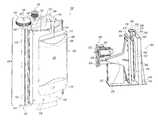
- FIG. 3is a first exemplary arrangement for an irrigation mounting system
- FIG. 4an enlarged view of a top portion of the irrigation mounting system shown in
- FIG. 3is a diagrammatic representation of FIG. 3 .
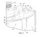
- FIG. 5is an enlarged view of the top portion of the irrigation mounting system shown in FIG. 3 with an irrigation container removed.
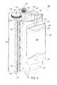
- FIG. 6is an enlarged view of a top portion of an alternative arrangement of an irrigation mounting system.
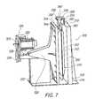
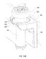
- FIG. 7is a perspective view of yet another alternative arrangement of an irrigation mounting system.
- FIG. 8is a top view of the irrigation mounting system arrangement of FIG. 7 .
- FIG. 9is a sideways elevational view of the irrigation mounting system arrangement of FIG. 7 .
- FIG. 10is an elevational view of an irrigation container for use in an irrigation mounting system.
- FIG. 11is an elevational view of an alternative arrangement of an irrigation container for use in an irrigation mounting system.
- FIG. 12is an elevational view of another alternative arrangement of an irrigation container for use in an irrigation mounting system.
- FIG. 13Ais an embodiment of a clip member for use with an irrigation mounting system.
- FIG. 13Bis an alternative embodiment of a clip member for use with an irrigation mounting system.
- FIGS. 14A-Bare views of yet another alternative arrangement of an irrigation mounting system.
- Irrigation mounting system 100comprises an irrigation container 102 , a mounting arm 104 , and an actuation device 106 .
- Irrigation container 102is configured as a compliant member, such as a compliant bag commonly supplied by Charter Medical, Lakewood, N.J., for surgical site infusion.
- irrigation container 102may be configured as a custom container specifically designed for this application.
- Irrigation container 102includes a body member 108 , a first sealed end 110 , and a second end 112 opposing first sealed end 110 .
- Body member 108may be made from any suitable material that provides container collapse without excessive stretching.
- a neck member 114ends outwardly from second end 112 and includes a stopper member 116 .
- Stopper member 116effectively seals the neck member 114 such that fluid stored in irrigation container 102 is prevented from unintentionally exiting irrigation container 102 .
- stopper member 116may be selectively pierced with a stopper spike to fluidly connect irrigation container to a surgical handpiece.
- Actuation device 106includes a base member 118 , a motor gear mount 120 , an actuation gear 122 , and a take-up reel 124 .
- secured to base member 118is a platen 126 .
- platen 126has a curved-shape configuration and is fixedly secured to base member 118 so as to form a convex mounting face 128 .
- Take-up reel 124includes a slot member 130 into which a first edge 131 of a compressing band 132 is fixedly received. While compressing band 132 was removed from FIG. 3 , it may be seen in FIG. 4 . A second edge 134 of compressing band 132 is fixedly secured to either the platen or a portion of base member 118 , opposite from take-up reel 124 .
- Take-up reel 124includes a rod member 136 disposed within take-up reel 124 .
- Rod member 136is defined by a first end 138 and a second end 140 .
- a portion of rod member 136is fixedly attached to take-up reel 124 .
- a first mounting flange 142is positioned adjacent first end 138 of rod member 136 .
- a second mounting flange 144is positioned adjacent to second end 140 of rod member 136 .
- Rod member 136is mounted to first and second mounting flanges 142 , 144 such that rod member 136 may be selectively rotated with respect to first and second mounting flanges 142 , 144 .
- First end 138 of rod member 136is mounted to first mounting flange 142 such that it extends outwardly from a top surface 146 of first mounting flange 142 .
- Actuation gear 122is fixedly attached to first end 138 of rod member 136 .
- Motor gear mount 120is operatively connected to a motor.
- a motor gearoperatively connects to motor gear mount 120 and interconnects with actuation gear 122 .
- actuation gear 122As the motor is activated, power is transmitted to actuation gear 122 causing actuation gear 122 to rotate.
- take-up reel 124rotates. Because first edge 131 of compressing band 132 is fixed to take-up reel 124 , as take-up reel 124 is rotated in a first direction, compressing band 132 is wound up onto take-up reel 124 . This action forces compressing band 132 to move towards platen 126 , thereby compressing body member 108 of irrigation container 102 against platen 126 .
- Take-up reel 124may also be rotated in a second direction to unwind compressing band 132 from take-up reel 124 , thereby providing clearance between platen 126 and compressing band 132 such that irrigation container 102 may be replaced.
- a groove 148is formed within platen 126 .
- Groove 148is configured to have a depth that is at least equal to the diameter of neck member 114 .
- neck member 114is disposed within groove 148 such that when compressing band 132 is actuated, neck member 114 does not become compressed or pinched between platen 126 and compressing band 132 .
- mounting arm 104is fixedly attached to a post member 150 .
- Post member 150is fixedly attached to base member 118 by any suitable manner so as to extend upwardly from a top edge of base member 118 .
- post member 150is secured to a first face 151 of base member 118 .
- post member 150may have an end portion fixed to a top edge of base member 118 rather than to first face 151 of base member 118 .
- mounting arm 104is arranged on post member 150 so as to extend outwardly from a mounting face 152 of post member 150 .
- mounting arm 104may be directly attached to base member 118 .
- mounting arm 104comprises a mounting end 154 and a supporting end 156 .
- supporting end 156is disposed so as to be spaced away from mounting face 152 such that supporting end 156 is arranged over groove 148 .
- the supporting end 156is configured with a cut-out portion 158 and a supporting flange 160 formed therein.
- supporting flange 160is recessed below a top surface 162 of mounting arm 104 , to be explained below in further detail.
- Mounting end 154may include an optional downwardly extending mounting flange 164 that abuts against mounting face 152 of post member 150 .
- mounting flange 164is generally configured as having an L-shaped cross-section. Suitable securing members are received within mounting flange 164 to secure supporting end 156 to post member 150 .
- mounting arm 104may be configured without mounting flange 164 .
- irrigation container 102is secured to irrigation mounting system 100 such that stopper 116 is positioned within supporting end 156 of mounting arm 104 .
- Supporting flange 160serves to support stopper 116 .
- irrigation container 102is oriented such that neck member 114 extends upwardly from body member 108 .
- irrigation container 102is oriented in a “neck-up” configuration. In this manner, air 166 within irrigation container 102 is disposed above the irrigation fluid 168 retained within irrigation container 102 such that it is in direct communication with neck member 114 . Thus, when the system is primed for use, air may be effectively evacuated from irrigation container 102 .
- stopper member 116may be configured with a frusto-conical shaped section 170 and a disc shaped distal end 172 .
- the disc shaped distal end 172is sized to fit within cut-out portion 158 .
- a bottom surface 174 of disc shaped distal end 172rests on supporting flange 160 .
- stopper member 116is positioned within cut-out portion 158 so as to form an articulating or gimbaled mount. In this manner, irrigation container 102 is positively and properly registered within irrigation mounting system 100 while permitting irrigation container 102 to change angles as irrigation container 102 is squeezed or depleted.
- stopper member 116forms an articulating mount, the proper position of neck member 114 within groove 148 may be maintained during operation of compressing band 132 , thereby preventing neck member 114 from getting inadvertently pinched or squeezed by compressing band 132 .
- stopper 116may be selectively fixedly engaged within cut-out 158 . More specifically, stopper 116 may be sized so as to snap into cut-out 158 to positively and rigidly engage stopper 116 with mounting arm 104 . This configuration provides a positive mount to permit spiking of stopper 116 to fluidly connect stopper 116 to the irrigation system. In the prior art, spiking of the stopper is typically accomplished by holding the irrigation container in one hand with the stopper facing the operator. However the irrigation container may slip, leading to inadvertent puncturing of the container or even the operator. Thus, a fixed engagement provides a support mechanism that prevents inadvertent movement of stopper 116 during the spiking operation.
- stopper 116may be selectively removed from mounting arm 104 and re-positioned on mounting arm 104 in an articulating mount.
- a contoured clip member 178may be positioned on neck member 114 , sufficiently below disc member 172 so as to permit disc member 172 to fixedly engage within cut-out 158 during the spiking operation.
- the contoured clip member 178is formed such that clip member may engage with cut-out 158 to properly position irrigation container 102 within irrigation supply mounting system 100 and maintain irrigation container 102 in a “neck-up” position, while permitting articulation of irrigation supply container 102 as fluid is depleted.
- contoured clip member 178may have an hourglass shape, such as that shown in FIG. 11 .
- clip member 178may be constructed of a generally flexible material and include a slit 180 to permit clip member 178 to be easily secured to a standard neck member 114 .
- clip member 178is shown as having an hourglass shape, it is understood that any suitable shape that would permit articulation of irrigation container 102 is contemplated by the present disclosure.
- a ball shaped clip member 182may be utilized, as shown in FIG. 12 .
- a rod member 184 ( FIG. 13A ) that is orientated generally perpendicular to neck member 114would also be suitable, as would a generally square member 186 ( FIG. 13B ) that receives mounting rods therethrough.
- mounting arm mechanism 200includes laterally opposing first and second mounting arms 202 , 204 , each defined by a supporting end 206 and a mounting end 208 .
- Supporting end 206is pivotally connected to a base member (not seen) of an irrigation supply mounting assembly, such as that shown in FIG. 3 .
- a biasing member 210operatively connects first and second mounting arms 202 , 204 together, a predetermined distance from one another.
- Formed within each mounting arm 202 , 204 at mounting end 208are mounting apertures 212 .
- a supporting groove 214may also be formed on an inner face 216 of each mounting arm 202 , 204 , adjacent mounting apertures 212 .
- mounting arms 202 , 204are secured to a base member of an irrigation supply mounting assembly.
- Mounting arms 202 , 204are secured such that inner faces 216 of each mounting arms 202 , 204 may pivot with respect to one another.
- Biasing member 217which may be constructed as a helical spring or other suitable member, serves to keep mounting arms 202 , 204 a predetermined distance from one another.
- application of a predetermined amount of force at mounting ends 208 on mounting arms 202 , 204may be applied to temporarily move mounting arms 202 , 204 apart from one another to permit a mounting clip, such as mounting clip 182 , to be received within mounting apertures 212 .
- clip member 182is configured to retain irrigation container 102 in an articulating manner such that as irrigation container 102 is squeezed or compressed and fluid is depleted therefrom, the angle of irrigation container 102 within the irrigation mounting system may selectively change without inadvertent pinching or compressing of neck member 114 .
- Irrigation mounting system 300comprises a generally planar first plate 302 , a generally planar second plate 304 , an actuation device 306 , a mounting arm 308 , and an irrigation container 310 .
- the first plate 302includes a front face 312 .
- First plate 302is configured so as to be mounted in a stationary manner.
- irrigation mounting system 300further comprises a mounting platform 314 to which a first end 316 of first plate 302 is fixed.
- Mounting arm 308is secured to a second end 318 of first plate 302 , to be explained in further detail below.
- Actuation device 306comprises a motor 320 that drives a motor gear 322 .
- Motor gear 322operatively engages a driving gear 324 that is fixed to a drive member 326 .
- Drive member 326is operatively engaged with an actuation arm 328 that is fixedly secured to second plate 304 .
- motor gear 322rotates driving gear 324 such that actuation aim 328 is moved laterally toward first plate 302 by drive member 326 .
- second plate 304is fixedly connected to actuation arm 328 , as motor 320 is actuation in the first direction, a front face 330 of second plate 304 is moved laterally toward front face 312 of first plate 302 .
- a support post 332may be provided to serve as a guide and support for actuation arm 328 . Support post 332 may be fixed to mounting platform 314 .
- Mounting arm 308secured to second end 318 of first plate 302 is mounting arm 308 .
- Mounting armincludes an upwardly extending support member 334 and a generally laterally extending mounting platform 336 .
- Mounting platform 336is configured to extend laterally outwardly from front face 312 of first plate 302 .
- Mounting platform 336includes a mounting aperture 338 that has an opening 339 formed on a first side edge 340 thereof. Opening 339 is positioned so as to be facing away from first faces 312 , 330 of first and second plates 302 , 304 , respectively.
- Irrigation container 310is configured as a conventional irrigation container and includes a body portion 342 in which irrigation fluid is sealed, a neck member 344 extending from body portion 342 , and a stopper member 346 .
- Stopper member 346includes an end portion 348 that is sized to be at least slightly larger than a diameter of opening 339 that leads into mounting aperture 338 formed on mounting platform 336 .
- end portion 348is disc shaped having a diameter that is larger than the diameter of opening 339 .
- the neck member 344may include a washer-shaped portion 1401 configured to fit into mounting aperture 338 .
- the washer-shaped portion 1401may have a larger diameter than the diameter of the mounting aperture 338 and, therefore, may sit inside the mounting aperture 338 .
- the washer-shaped portion 1401may include a groove 1403 that mates with a raised portion 1405 on the inside of mounting aperture 338 .
- Other shapes for the end portion 348are also contemplated (e.g., tapered conical, elliptical, tear drop, etc).
- second plate 304is moved away from first plate 302 so as to provide a gap between faces 312 , 330 of first and second plates 302 , 304 , respectively.
- irrigation container 310is positioned between first and second plates 302 , 304 such that neck member 344 is oriented to extend upwardly from body portion 342 of irrigation container 310 .
- a portion of stopper 346is retained within mounting aperture 338 of mounting platform 336 . More specifically, mounting aperture 338 is configured to receive a portion of stopper 346 below end portion 348 . Because end portion 348 is slightly larger than mounting aperture 338 , a bottom surface 350 engages a top surface 352 of mounting platform 336 .
- irrigation container 310is thus suspended from mounting platform 336 .
- mounting platform 336extends laterally outwardly from first face 312 of first plate 302 , irrigation container 310 permitted to freely suspend from mounting platform 336 such that it may articulate in response to changes in fluid levels within irrigation container 310 .
- Stopper 346may be spiked and operatively connected to a fluid delivery system either before or after being secured to mounting platform 336 . Once irrigation container 310 is secured to mounting platform 336 , air entrained within irrigation container 310 will be disposed within a top portion of irrigation container 310 , thus making the priming operation for the irrigation system effective to evacuate the air from irrigation container 310 .
- motor 306may be activated to move second plate 304 toward first plate 302 , thereby compressing irrigation container 310 between first and second plates 302 , 304 at a predetermined speed or time interval to effectively deliver irrigation fluid from irrigation container 310 .
- the speed of compressione.g., the speed of the compression band 132 towards platen 126
- the speed of compressionmay be constant throughout the delivery of the irrigation fluid 168 .
- the speed of compressionmay be variable.
- the speed of compressionmay be based on a position of a footswitch or on compression speed versus time plot (e.g., provided by the surgeon or console).
- the speed of compressionmay be adjusted to compensate for different fluid amounts in the irrigation container.
- the compressing band 132may need to be compressed at different rates (based, for example, on the irrigation container configuration and/or amount of remaining irrigation fluid 168 ) during an irrigation container's life cycle to provide the same flow of irrigation fluid 168 .
- Other rates of compressionare also contemplated by the present disclosure. Because irrigation container 310 is suspended from mounting platform 336 , it may freely articulate in response to the changing shape of irrigation container 310 as it is compressed between first and second plates 302 , 304 .
Landscapes
- Health & Medical Sciences (AREA)
- Public Health (AREA)
- Veterinary Medicine (AREA)
- Life Sciences & Earth Sciences (AREA)
- Animal Behavior & Ethology (AREA)
- General Health & Medical Sciences (AREA)
- Engineering & Computer Science (AREA)
- Biomedical Technology (AREA)
- Heart & Thoracic Surgery (AREA)
- Hematology (AREA)
- Anesthesiology (AREA)
- Vascular Medicine (AREA)
- Ophthalmology & Optometry (AREA)
- Pharmacology & Pharmacy (AREA)
- Nuclear Medicine, Radiotherapy & Molecular Imaging (AREA)
- Surgery (AREA)
- Epidemiology (AREA)
- Pain & Pain Management (AREA)
- Physical Education & Sports Medicine (AREA)
- Rehabilitation Therapy (AREA)
- Infusion, Injection, And Reservoir Apparatuses (AREA)
- Agricultural Chemicals And Associated Chemicals (AREA)
Abstract
Description
Claims (20)
Priority Applications (11)
| Application Number | Priority Date | Filing Date | Title |
|---|---|---|---|
| US12/844,257US8136779B2 (en) | 2010-07-27 | 2010-07-27 | Mounting arrangement for a pressurized irrigation system |
| EP11812916.2AEP2582988B1 (en) | 2010-07-27 | 2011-06-28 | Mounting arrangement for a pressurized irrigation system |
| CA2803877ACA2803877C (en) | 2010-07-27 | 2011-06-28 | Mounting arrangement for a pressurized irrigation system |
| ES11812916.2TES2564856T3 (en) | 2010-07-27 | 2011-06-28 | Mounting arrangement for a pressurized irrigation system |
| BR112013002086-5ABR112013002086B1 (en) | 2010-07-27 | 2011-06-28 | MOUNTING ARRANGEMENT FOR A PRESSURIZED IRRIGATION SYSTEM |
| RU2013108666/14ARU2568537C2 (en) | 2010-07-27 | 2011-06-28 | Installation scheme for displacing irrigation system |
| PCT/US2011/042075WO2012015552A1 (en) | 2010-07-27 | 2011-06-28 | Mounting arrangement for a pressurized irrigation system |
| JP2013521787AJP5990166B2 (en) | 2010-07-27 | 2011-06-28 | Mounting structure for pressurized perfusion system |
| AU2011283132AAU2011283132B2 (en) | 2010-07-27 | 2011-06-28 | Mounting arrangement for a pressurized irrigation system |
| CN201180036425.2ACN103026077B (en) | 2010-07-27 | 2011-06-28 | For the erecting device of enhancing perfusion system |
| AU2014215954AAU2014215954C1 (en) | 2010-07-27 | 2014-08-20 | Mounting arrangement for a pressurized irrigation system |
Applications Claiming Priority (1)
| Application Number | Priority Date | Filing Date | Title |
|---|---|---|---|
| US12/844,257US8136779B2 (en) | 2010-07-27 | 2010-07-27 | Mounting arrangement for a pressurized irrigation system |
Publications (2)
| Publication Number | Publication Date |
|---|---|
| US20120025047A1 US20120025047A1 (en) | 2012-02-02 |
| US8136779B2true US8136779B2 (en) | 2012-03-20 |
Family
ID=45525747
Family Applications (1)
| Application Number | Title | Priority Date | Filing Date |
|---|---|---|---|
| US12/844,257ActiveUS8136779B2 (en) | 2010-07-27 | 2010-07-27 | Mounting arrangement for a pressurized irrigation system |
Country Status (10)
| Country | Link |
|---|---|
| US (1) | US8136779B2 (en) |
| EP (1) | EP2582988B1 (en) |
| JP (1) | JP5990166B2 (en) |
| CN (1) | CN103026077B (en) |
| AU (1) | AU2011283132B2 (en) |
| BR (1) | BR112013002086B1 (en) |
| CA (1) | CA2803877C (en) |
| ES (1) | ES2564856T3 (en) |
| RU (1) | RU2568537C2 (en) |
| WO (1) | WO2012015552A1 (en) |
Cited By (16)
| Publication number | Priority date | Publication date | Assignee | Title |
|---|---|---|---|---|
| USD681882S1 (en)* | 2011-11-10 | 2013-05-07 | Medi-Plan Co., Ltd | Fire extinguisher ball |
| USD699343S1 (en) | 2011-12-20 | 2014-02-11 | Alcon Research, Ltd. | Irrigation solution bag |
| USD740958S1 (en)* | 2014-10-10 | 2015-10-13 | Terumo Bct, Inc. | Centrifuge counter balance bag |
| US9549850B2 (en) | 2013-04-26 | 2017-01-24 | Novartis Ag | Partial venting system for occlusion surge mitigation |
| US9561321B2 (en) | 2011-12-08 | 2017-02-07 | Alcon Research, Ltd. | Selectively moveable valve elements for aspiration and irrigation circuits |
| US9936863B2 (en) | 2012-06-27 | 2018-04-10 | Camplex, Inc. | Optical assembly providing a surgical microscope view for a surgical visualization system |
| US10000313B2 (en)* | 2016-03-23 | 2018-06-19 | Obschestvo s organichennoi otvetstvenostju “Mistral Alko” | Holder with bottle |
| US10028651B2 (en) | 2013-09-20 | 2018-07-24 | Camplex, Inc. | Surgical visualization systems and displays |
| US20180369457A1 (en)* | 2017-06-24 | 2018-12-27 | Megadyne Medical Products, Inc. | Vacuum assisted irrigation pump |
| US10555728B2 (en) | 2012-06-27 | 2020-02-11 | Camplex, Inc. | Surgical visualization system |
| US10568499B2 (en) | 2013-09-20 | 2020-02-25 | Camplex, Inc. | Surgical visualization systems and displays |
| US10702353B2 (en) | 2014-12-05 | 2020-07-07 | Camplex, Inc. | Surgical visualizations systems and displays |
| US10918455B2 (en) | 2017-05-08 | 2021-02-16 | Camplex, Inc. | Variable light source |
| US10932766B2 (en) | 2013-05-21 | 2021-03-02 | Camplex, Inc. | Surgical visualization systems |
| US10966798B2 (en) | 2015-11-25 | 2021-04-06 | Camplex, Inc. | Surgical visualization systems and displays |
| US11154378B2 (en) | 2015-03-25 | 2021-10-26 | Camplex, Inc. | Surgical visualization systems and displays |
Families Citing this family (7)
| Publication number | Priority date | Publication date | Assignee | Title |
|---|---|---|---|---|
| US8272611B2 (en)* | 2009-11-01 | 2012-09-25 | Sports Solutions, Inc. | Bracket with locking mechanism for fluid dispenser |
| EP2691143B1 (en)* | 2011-03-30 | 2019-05-29 | Flow Med Ltd | A continuous and controlled irrigation system |
| US9663259B2 (en)* | 2015-02-27 | 2017-05-30 | Pall Corporation | Gas evacuation system and method |
| CN106214480B (en)* | 2016-08-11 | 2023-07-25 | 重庆医科大学附属永川医院 | A storage bottle for medical spray liquid |
| CN112472413B (en)* | 2019-09-11 | 2023-06-16 | 微创视神医疗科技(上海)有限公司 | Active perfusion system for ultrasonic emulsification |
| KR20240055761A (en)* | 2021-09-02 | 2024-04-29 | 밸테크 어소시에이츠, 인크. | Bag hangers for clean room environments |
| WO2024238721A2 (en)* | 2023-05-17 | 2024-11-21 | Twenty Twenty Therapeutics Llc | Fluid delivery device |
Citations (50)
| Publication number | Priority date | Publication date | Assignee | Title |
|---|---|---|---|---|
| US3589363A (en) | 1967-07-25 | 1971-06-29 | Cavitron Corp | Material removal apparatus and method employing high frequency vibrations |
| US4029094A (en) | 1975-03-04 | 1977-06-14 | Union Chimique Continentale - U.C.C. Societe Anonyme | Device for regulating perfusion flowrate |
| US4184510A (en) | 1977-03-15 | 1980-01-22 | Fibra-Sonics, Inc. | Valued device for controlling vacuum in surgery |
| US4223676A (en) | 1977-12-19 | 1980-09-23 | Cavitron Corporation | Ultrasonic aspirator |
| US4246902A (en) | 1978-03-10 | 1981-01-27 | Miguel Martinez | Surgical cutting instrument |
| US4411652A (en)* | 1981-08-21 | 1983-10-25 | The Regents Of The University Of California | Internally sterile pulsatile infusor system |
| US4493694A (en) | 1980-10-17 | 1985-01-15 | Cooper Lasersonics, Inc. | Surgical pre-aspirator |
| US4515583A (en) | 1983-10-17 | 1985-05-07 | Coopervision, Inc. | Operative elliptical probe for ultrasonic surgical instrument and method of its use |
| US4589415A (en) | 1984-08-31 | 1986-05-20 | Haaga John R | Method and system for fragmenting kidney stones |
| US4609368A (en) | 1984-08-22 | 1986-09-02 | Dotson Robert S Jun | Pneumatic ultrasonic surgical handpiece |
| US4813927A (en) | 1987-09-22 | 1989-03-21 | Vitreoretinal Development, Inc. | Parallel infusion apparatus and method |
| US4869715A (en) | 1988-04-21 | 1989-09-26 | Sherburne Fred S | Ultrasonic cone and method of construction |
| US4900301A (en) | 1987-09-22 | 1990-02-13 | Vitreoretinal Development, Inc. | Method for ocular perfusion |
| US4909786A (en) | 1987-12-17 | 1990-03-20 | W. M. H. Kerbosch B.V. | Apparatus for controlling the flow of an infusion fluid in an infusion system |
| US4922902A (en) | 1986-05-19 | 1990-05-08 | Valleylab, Inc. | Method for removing cellular material with endoscopic ultrasonic aspirator |
| WO1990008562A1 (en) | 1989-02-02 | 1990-08-09 | Sinergy S.A. | Irrigation and suction apparatus usable in endoscopic surgery |
| US4989583A (en) | 1988-10-21 | 1991-02-05 | Nestle S.A. | Ultrasonic cutting tip assembly |
| US5032111A (en) | 1987-09-22 | 1991-07-16 | Vitreoretinal Development, Inc. | Method and apparatus for ocular perfusion |
| US5047009A (en) | 1987-09-22 | 1991-09-10 | Vitreoretinal Development, Inc. | Method and apparatus for ocular perfusion |
| US5154694A (en) | 1989-06-06 | 1992-10-13 | Kelman Charles D | Tissue scraper device for medical use |
| US5160317A (en) | 1991-01-03 | 1992-11-03 | Costin John A | Computer controlled smart phacoemulsification method and apparatus |
| US5179606A (en) | 1989-05-19 | 1993-01-12 | Nec Corporation | Optical coupler |
| US5279547A (en) | 1991-01-03 | 1994-01-18 | Alcon Surgical Inc. | Computer controlled smart phacoemulsification method and apparatus |
| US5330431A (en) | 1993-03-12 | 1994-07-19 | Glenn Herskowitz | Infusion pump |
| US5342313A (en) | 1992-11-02 | 1994-08-30 | Infusion Technologies Corporation | Fluid pump for a flexible, variable geometry reservoir |
| US5399166A (en) | 1992-11-23 | 1995-03-21 | Laing; David H. | Portable infusion device |
| US5403276A (en) | 1993-02-16 | 1995-04-04 | Danek Medical, Inc. | Apparatus for minimally invasive tissue removal |
| WO1995020374A1 (en) | 1994-01-28 | 1995-08-03 | Allergan | Method and apparatus for controlling irrigation and aspiration of fluids during surgical procedures on the eye |
| WO1995020373A1 (en) | 1994-01-26 | 1995-08-03 | Klaus Bertram | Device for removing foreign bodies from the eye |
| FR2727847A1 (en) | 1994-12-07 | 1996-06-14 | C & D Biomedical | Appts. for supply and extraction of clarifying liquid during surgery, e.g. bladder operations |
| US5536254A (en) | 1992-02-20 | 1996-07-16 | Advanced Surgical Products, Inc. | Laparoscopic irrigation bottle pump |
| US5586973A (en) | 1991-04-22 | 1996-12-24 | C & D Biomedical S.A. | Method and device for controlled irrigation and suctioning of a liquid clarificant during endoscopic surgery |
| US5591127A (en) | 1994-01-28 | 1997-01-07 | Barwick, Jr.; Billie J. | Phacoemulsification method and apparatus |
| US5643304A (en) | 1993-02-16 | 1997-07-01 | Danek Medical, Inc. | Method and apparatus for minimally invasive tissue removal |
| US5697525A (en)* | 1993-02-10 | 1997-12-16 | Daniel Joseph O'Reilly | Bag for dispensing fluid material and a dispenser having the bag |
| US5733256A (en) | 1996-09-26 | 1998-03-31 | Micro Medical Devices | Integrated phacoemulsification system |
| US5766146A (en) | 1996-04-04 | 1998-06-16 | Allergan | Method of infusion control during phacoemulsification surgery |
| US5836909A (en) | 1996-09-13 | 1998-11-17 | Cosmescu; Ioan | Automatic fluid control system for use in open and laparoscopic laser surgery and electrosurgery and method therefor |
| US5865764A (en) | 1996-12-30 | 1999-02-02 | Armoor Opthalmics, Inc. | Device and method for noninvasive measurement of internal pressure within body cavities |
| WO1999045868A1 (en) | 1998-03-10 | 1999-09-16 | Allergan Sales, Inc. | Temperature controler and method for phacoemulsification |
| WO2000027275A1 (en) | 1998-11-06 | 2000-05-18 | Alex Urich | Phacoemulsification apparatus with personal computer |
| US6083189A (en) | 1996-06-21 | 2000-07-04 | Saphir Medical | Bifunctional liquid dispensing generator, in particular for sterilized liquids |
| US6126129A (en)* | 1998-12-18 | 2000-10-03 | Herron; Terry | Apparatus and method for supporting an intravenous solution containment vessel |
| EP1062958A1 (en) | 1999-06-18 | 2000-12-27 | Alcon Laboratories, Inc. | A control system for controlling the operating parameters of a surgical system |
| WO2000078372A1 (en) | 1999-06-18 | 2000-12-28 | Alcon Laboratories, Inc. | Infusion control system |
| US6206014B1 (en) | 1999-03-26 | 2001-03-27 | American Optisurgical Incorporated | Automated system for rinsing a fluid line of a medical system |
| US6450215B1 (en) | 2000-09-29 | 2002-09-17 | Charter Medical, Ltd. | Apparatus and method for filling bags |
| US20060100580A1 (en)* | 2004-10-30 | 2006-05-11 | Jost Muller | Device for medical infusions |
| US20100012807A1 (en)* | 2008-07-17 | 2010-01-21 | David Michael Perman | Bottle Holder |
| US7806865B1 (en) | 2009-05-20 | 2010-10-05 | Alcon Research, Ltd. | Pressurized irrigation squeeze band |
Family Cites Families (10)
| Publication number | Priority date | Publication date | Assignee | Title |
|---|---|---|---|---|
| US3872868A (en)* | 1973-09-27 | 1975-03-25 | Joel B Kline | Universal hospital container |
| DE3570189D1 (en)* | 1985-01-23 | 1989-06-22 | Saul Leibinsohn | Device for dispensing a liquid from a collapsible container |
| JP2584688B2 (en)* | 1990-08-17 | 1997-02-26 | テルモ株式会社 | Liquid separation device and compression device |
| JP2565598Y2 (en)* | 1991-10-24 | 1998-03-18 | 釜屋化学工業株式会社 | Stand for holding bag containers |
| JP2000049585A (en)* | 1998-07-31 | 2000-02-18 | Fujitsu Ltd | Output buffer circuit |
| DE10063975A1 (en)* | 2000-12-20 | 2002-06-27 | Roland Wex | Mechanically operated liquid pump |
| RU22750U1 (en)* | 2001-12-19 | 2002-04-27 | Луценко Юрий Леонидович | DEVICE FOR PREVENTIVE AND TREATMENT IRRIGATION |
| JP2006051281A (en)* | 2004-08-16 | 2006-02-23 | Daiken Iki Kk | Chemical pressure injection device |
| CN2875467Y (en)* | 2006-03-13 | 2007-03-07 | 陈长辉 | Sealed dust-proof constant-pressure type transfusion (or blood-transfusion) device |
| DK2470242T3 (en)* | 2009-08-27 | 2018-03-12 | Sanofi Aventis Deutschland | DRUG CONTAINER |
- 2010
- 2010-07-27USUS12/844,257patent/US8136779B2/enactiveActive
- 2011
- 2011-06-28EPEP11812916.2Apatent/EP2582988B1/enactiveActive
- 2011-06-28ESES11812916.2Tpatent/ES2564856T3/enactiveActive
- 2011-06-28AUAU2011283132Apatent/AU2011283132B2/enactiveActive
- 2011-06-28CNCN201180036425.2Apatent/CN103026077B/enactiveActive
- 2011-06-28RURU2013108666/14Apatent/RU2568537C2/ennot_activeIP Right Cessation
- 2011-06-28BRBR112013002086-5Apatent/BR112013002086B1/ennot_activeIP Right Cessation
- 2011-06-28JPJP2013521787Apatent/JP5990166B2/enactiveActive
- 2011-06-28WOPCT/US2011/042075patent/WO2012015552A1/enactiveApplication Filing
- 2011-06-28CACA2803877Apatent/CA2803877C/enactiveActive
Patent Citations (62)
| Publication number | Priority date | Publication date | Assignee | Title |
|---|---|---|---|---|
| US3589363A (en) | 1967-07-25 | 1971-06-29 | Cavitron Corp | Material removal apparatus and method employing high frequency vibrations |
| US4029094A (en) | 1975-03-04 | 1977-06-14 | Union Chimique Continentale - U.C.C. Societe Anonyme | Device for regulating perfusion flowrate |
| US4184510A (en) | 1977-03-15 | 1980-01-22 | Fibra-Sonics, Inc. | Valued device for controlling vacuum in surgery |
| US4223676A (en) | 1977-12-19 | 1980-09-23 | Cavitron Corporation | Ultrasonic aspirator |
| US4246902A (en) | 1978-03-10 | 1981-01-27 | Miguel Martinez | Surgical cutting instrument |
| US4493694A (en) | 1980-10-17 | 1985-01-15 | Cooper Lasersonics, Inc. | Surgical pre-aspirator |
| US4411652A (en)* | 1981-08-21 | 1983-10-25 | The Regents Of The University Of California | Internally sterile pulsatile infusor system |
| US4515583A (en) | 1983-10-17 | 1985-05-07 | Coopervision, Inc. | Operative elliptical probe for ultrasonic surgical instrument and method of its use |
| US4609368A (en) | 1984-08-22 | 1986-09-02 | Dotson Robert S Jun | Pneumatic ultrasonic surgical handpiece |
| US4589415A (en) | 1984-08-31 | 1986-05-20 | Haaga John R | Method and system for fragmenting kidney stones |
| US4922902A (en) | 1986-05-19 | 1990-05-08 | Valleylab, Inc. | Method for removing cellular material with endoscopic ultrasonic aspirator |
| US4813927A (en) | 1987-09-22 | 1989-03-21 | Vitreoretinal Development, Inc. | Parallel infusion apparatus and method |
| US4900301A (en) | 1987-09-22 | 1990-02-13 | Vitreoretinal Development, Inc. | Method for ocular perfusion |
| US5032111A (en) | 1987-09-22 | 1991-07-16 | Vitreoretinal Development, Inc. | Method and apparatus for ocular perfusion |
| US5047009A (en) | 1987-09-22 | 1991-09-10 | Vitreoretinal Development, Inc. | Method and apparatus for ocular perfusion |
| US4909786A (en) | 1987-12-17 | 1990-03-20 | W. M. H. Kerbosch B.V. | Apparatus for controlling the flow of an infusion fluid in an infusion system |
| US4869715A (en) | 1988-04-21 | 1989-09-26 | Sherburne Fred S | Ultrasonic cone and method of construction |
| US4989583A (en) | 1988-10-21 | 1991-02-05 | Nestle S.A. | Ultrasonic cutting tip assembly |
| US5359996A (en) | 1988-10-21 | 1994-11-01 | Nestle, S.A. | Ultrasonic cutting tip and assembly |
| US5178606A (en) | 1989-02-02 | 1993-01-12 | Societe Dite Sinergy S.A., A French Corp. | Irrigation and aspiration apparatus for use in endoscopic surgery |
| WO1990008562A1 (en) | 1989-02-02 | 1990-08-09 | Sinergy S.A. | Irrigation and suction apparatus usable in endoscopic surgery |
| US5179606A (en) | 1989-05-19 | 1993-01-12 | Nec Corporation | Optical coupler |
| US5154694A (en) | 1989-06-06 | 1992-10-13 | Kelman Charles D | Tissue scraper device for medical use |
| US5279547A (en) | 1991-01-03 | 1994-01-18 | Alcon Surgical Inc. | Computer controlled smart phacoemulsification method and apparatus |
| US5160317A (en) | 1991-01-03 | 1992-11-03 | Costin John A | Computer controlled smart phacoemulsification method and apparatus |
| US5520633A (en) | 1991-01-03 | 1996-05-28 | Costin; John A. | Computer controlled smart phacoemulsification method and apparatus |
| US5586973A (en) | 1991-04-22 | 1996-12-24 | C & D Biomedical S.A. | Method and device for controlled irrigation and suctioning of a liquid clarificant during endoscopic surgery |
| US5536254A (en) | 1992-02-20 | 1996-07-16 | Advanced Surgical Products, Inc. | Laparoscopic irrigation bottle pump |
| US5342313A (en) | 1992-11-02 | 1994-08-30 | Infusion Technologies Corporation | Fluid pump for a flexible, variable geometry reservoir |
| US5399166A (en) | 1992-11-23 | 1995-03-21 | Laing; David H. | Portable infusion device |
| US5697525A (en)* | 1993-02-10 | 1997-12-16 | Daniel Joseph O'Reilly | Bag for dispensing fluid material and a dispenser having the bag |
| US5403276A (en) | 1993-02-16 | 1995-04-04 | Danek Medical, Inc. | Apparatus for minimally invasive tissue removal |
| US5685840A (en) | 1993-02-16 | 1997-11-11 | Danek Medical, Inc. | Method and apparatus for minimally invasive tissue removal |
| US5643304A (en) | 1993-02-16 | 1997-07-01 | Danek Medical, Inc. | Method and apparatus for minimally invasive tissue removal |
| US5330431A (en) | 1993-03-12 | 1994-07-19 | Glenn Herskowitz | Infusion pump |
| WO1995020373A1 (en) | 1994-01-26 | 1995-08-03 | Klaus Bertram | Device for removing foreign bodies from the eye |
| WO1995020374A1 (en) | 1994-01-28 | 1995-08-03 | Allergan | Method and apparatus for controlling irrigation and aspiration of fluids during surgical procedures on the eye |
| US5700240A (en) | 1994-01-28 | 1997-12-23 | Barwick, Jr.; Billie John | Phacoemulsification system having ultrasonic power controlled by aspiration vacuum sensor |
| US5591127A (en) | 1994-01-28 | 1997-01-07 | Barwick, Jr.; Billie J. | Phacoemulsification method and apparatus |
| FR2727847A1 (en) | 1994-12-07 | 1996-06-14 | C & D Biomedical | Appts. for supply and extraction of clarifying liquid during surgery, e.g. bladder operations |
| US5766146A (en) | 1996-04-04 | 1998-06-16 | Allergan | Method of infusion control during phacoemulsification surgery |
| US6083189A (en) | 1996-06-21 | 2000-07-04 | Saphir Medical | Bifunctional liquid dispensing generator, in particular for sterilized liquids |
| US5836909A (en) | 1996-09-13 | 1998-11-17 | Cosmescu; Ioan | Automatic fluid control system for use in open and laparoscopic laser surgery and electrosurgery and method therefor |
| US5733256A (en) | 1996-09-26 | 1998-03-31 | Micro Medical Devices | Integrated phacoemulsification system |
| US5865764A (en) | 1996-12-30 | 1999-02-02 | Armoor Opthalmics, Inc. | Device and method for noninvasive measurement of internal pressure within body cavities |
| WO1999045868A1 (en) | 1998-03-10 | 1999-09-16 | Allergan Sales, Inc. | Temperature controler and method for phacoemulsification |
| US6083193A (en) | 1998-03-10 | 2000-07-04 | Allergan Sales, Inc. | Thermal mode phaco apparatus and method |
| US6699212B1 (en) | 1998-03-10 | 2004-03-02 | Advanced Medical Optics | Phaco thermal control apparatus and method |
| WO2000027275A1 (en) | 1998-11-06 | 2000-05-18 | Alex Urich | Phacoemulsification apparatus with personal computer |
| US6155975A (en) | 1998-11-06 | 2000-12-05 | Urich; Alex | Phacoemulsification apparatus with personal computer |
| US6126129A (en)* | 1998-12-18 | 2000-10-03 | Herron; Terry | Apparatus and method for supporting an intravenous solution containment vessel |
| US6206014B1 (en) | 1999-03-26 | 2001-03-27 | American Optisurgical Incorporated | Automated system for rinsing a fluid line of a medical system |
| WO2000078372A1 (en) | 1999-06-18 | 2000-12-28 | Alcon Laboratories, Inc. | Infusion control system |
| US6179808B1 (en) | 1999-06-18 | 2001-01-30 | Alcon Laboratories, Inc. | Method of controlling the operating parameters of a surgical system |
| EP1062958B1 (en) | 1999-06-18 | 2002-04-24 | Alcon Laboratories, Inc. | Software for controlling the operating parameters of a surgical system |
| US20020077587A1 (en) | 1999-06-18 | 2002-06-20 | Mikhail Boukhny | Infusion control system |
| US6491661B1 (en) | 1999-06-18 | 2002-12-10 | Alcon Manufacturing, Ltd. | Infusion control system |
| EP1062958A1 (en) | 1999-06-18 | 2000-12-27 | Alcon Laboratories, Inc. | A control system for controlling the operating parameters of a surgical system |
| US6450215B1 (en) | 2000-09-29 | 2002-09-17 | Charter Medical, Ltd. | Apparatus and method for filling bags |
| US20060100580A1 (en)* | 2004-10-30 | 2006-05-11 | Jost Muller | Device for medical infusions |
| US20100012807A1 (en)* | 2008-07-17 | 2010-01-21 | David Michael Perman | Bottle Holder |
| US7806865B1 (en) | 2009-05-20 | 2010-10-05 | Alcon Research, Ltd. | Pressurized irrigation squeeze band |
Non-Patent Citations (2)
| Title |
|---|
| International Searching Authority, International Search Report, PCT/US2011/042075, Sep. 7, 2011, 4 pages. |
| International Searching Authority, Written Opinion of the International Searching Authority, PCT/ US2011/042075, Sep. 7, 2011, 3 pages. |
Cited By (28)
| Publication number | Priority date | Publication date | Assignee | Title |
|---|---|---|---|---|
| USD681882S1 (en)* | 2011-11-10 | 2013-05-07 | Medi-Plan Co., Ltd | Fire extinguisher ball |
| US9561321B2 (en) | 2011-12-08 | 2017-02-07 | Alcon Research, Ltd. | Selectively moveable valve elements for aspiration and irrigation circuits |
| USD699343S1 (en) | 2011-12-20 | 2014-02-11 | Alcon Research, Ltd. | Irrigation solution bag |
| US11129521B2 (en) | 2012-06-27 | 2021-09-28 | Camplex, Inc. | Optics for video camera on a surgical visualization system |
| US10925589B2 (en) | 2012-06-27 | 2021-02-23 | Camplex, Inc. | Interface for viewing video from cameras on a surgical visualization system |
| US9936863B2 (en) | 2012-06-27 | 2018-04-10 | Camplex, Inc. | Optical assembly providing a surgical microscope view for a surgical visualization system |
| US11889976B2 (en) | 2012-06-27 | 2024-02-06 | Camplex, Inc. | Surgical visualization systems |
| US10022041B2 (en) | 2012-06-27 | 2018-07-17 | Camplex, Inc. | Hydraulic system for surgical applications |
| US11389146B2 (en) | 2012-06-27 | 2022-07-19 | Camplex, Inc. | Surgical visualization system |
| US11166706B2 (en) | 2012-06-27 | 2021-11-09 | Camplex, Inc. | Surgical visualization systems |
| US10231607B2 (en) | 2012-06-27 | 2019-03-19 | Camplex, Inc. | Surgical visualization systems |
| US10555728B2 (en) | 2012-06-27 | 2020-02-11 | Camplex, Inc. | Surgical visualization system |
| US10925472B2 (en) | 2012-06-27 | 2021-02-23 | Camplex, Inc. | Binocular viewing assembly for a surgical visualization system |
| US9549850B2 (en) | 2013-04-26 | 2017-01-24 | Novartis Ag | Partial venting system for occlusion surge mitigation |
| US10932766B2 (en) | 2013-05-21 | 2021-03-02 | Camplex, Inc. | Surgical visualization systems |
| US11147443B2 (en) | 2013-09-20 | 2021-10-19 | Camplex, Inc. | Surgical visualization systems and displays |
| US10881286B2 (en) | 2013-09-20 | 2021-01-05 | Camplex, Inc. | Medical apparatus for use with a surgical tubular retractor |
| US10568499B2 (en) | 2013-09-20 | 2020-02-25 | Camplex, Inc. | Surgical visualization systems and displays |
| US10028651B2 (en) | 2013-09-20 | 2018-07-24 | Camplex, Inc. | Surgical visualization systems and displays |
| USD740958S1 (en)* | 2014-10-10 | 2015-10-13 | Terumo Bct, Inc. | Centrifuge counter balance bag |
| US10702353B2 (en) | 2014-12-05 | 2020-07-07 | Camplex, Inc. | Surgical visualizations systems and displays |
| US11154378B2 (en) | 2015-03-25 | 2021-10-26 | Camplex, Inc. | Surgical visualization systems and displays |
| US10966798B2 (en) | 2015-11-25 | 2021-04-06 | Camplex, Inc. | Surgical visualization systems and displays |
| US10000313B2 (en)* | 2016-03-23 | 2018-06-19 | Obschestvo s organichennoi otvetstvenostju “Mistral Alko” | Holder with bottle |
| US10918455B2 (en) | 2017-05-08 | 2021-02-16 | Camplex, Inc. | Variable light source |
| US10478533B2 (en)* | 2017-06-24 | 2019-11-19 | Megadyne Medical Products, Inc. | Vacuum assisted irrigation pump |
| US20180369457A1 (en)* | 2017-06-24 | 2018-12-27 | Megadyne Medical Products, Inc. | Vacuum assisted irrigation pump |
| US11446416B2 (en) | 2017-06-24 | 2022-09-20 | Megadyne Medical Products, Inc. | Vacuum assisted irrigation pump |
Also Published As
| Publication number | Publication date |
|---|---|
| CA2803877C (en) | 2018-08-14 |
| WO2012015552A1 (en) | 2012-02-02 |
| EP2582988B1 (en) | 2016-01-06 |
| AU2011283132A1 (en) | 2013-01-24 |
| CA2803877A1 (en) | 2012-02-02 |
| BR112013002086A2 (en) | 2016-05-24 |
| JP2013538074A (en) | 2013-10-10 |
| RU2568537C2 (en) | 2015-11-20 |
| CN103026077A (en) | 2013-04-03 |
| JP5990166B2 (en) | 2016-09-07 |
| BR112013002086B1 (en) | 2019-09-17 |
| CN103026077B (en) | 2016-03-16 |
| ES2564856T3 (en) | 2016-03-29 |
| EP2582988A4 (en) | 2013-12-11 |
| AU2011283132B2 (en) | 2014-07-17 |
| RU2013108666A (en) | 2014-09-10 |
| US20120025047A1 (en) | 2012-02-02 |
| EP2582988A1 (en) | 2013-04-24 |
Similar Documents
| Publication | Publication Date | Title |
|---|---|---|
| US8136779B2 (en) | Mounting arrangement for a pressurized irrigation system | |
| AU2013257535B2 (en) | Phacoemulsification hand piece with integrated aspiration pump | |
| ES2729166T3 (en) | Viscous fluid injector | |
| KR101287163B1 (en) | Intraocular pressure control | |
| US9877823B2 (en) | Corneal implant retaining devices and methods of use | |
| US20110144567A1 (en) | Phacoemulsification Hand Piece With Integrated Aspiration Pump and Cartridge | |
| US6723065B2 (en) | Intraocular surgical apparatus | |
| WO2011057065A1 (en) | Apparatuses and methods for delivering substances to the inner eye | |
| JP2024503739A (en) | Method and device for subretinal injection | |
| AU2014215954B2 (en) | Mounting arrangement for a pressurized irrigation system | |
| US20050245886A1 (en) | Anti-ocular chamber collapse sleeve | |
| CN215134646U (en) | Medical infusion device with arm supporting structure | |
| CN118718163A (en) | An anti-extravasation chemotherapy drug delivery device for oncology |
Legal Events
| Date | Code | Title | Description |
|---|---|---|---|
| AS | Assignment | Owner name:ALCON RESEARCH, LTD., TEXAS Free format text:ASSIGNMENT OF ASSIGNORS INTEREST;ASSIGNORS:WILSON, DANIEL J.;CHON, JAMES Y.;REEL/FRAME:024833/0391 Effective date:20100715 | |
| STCF | Information on status: patent grant | Free format text:PATENTED CASE | |
| FPAY | Fee payment | Year of fee payment:4 | |
| MAFP | Maintenance fee payment | Free format text:PAYMENT OF MAINTENANCE FEE, 8TH YEAR, LARGE ENTITY (ORIGINAL EVENT CODE: M1552); ENTITY STATUS OF PATENT OWNER: LARGE ENTITY Year of fee payment:8 | |
| AS | Assignment | Owner name:ALCON INC., SWITZERLAND Free format text:CONFIRMATORY DEED OF ASSIGNMENT EFFECTIVE APRIL 8, 2019;ASSIGNOR:NOVARTIS AG;REEL/FRAME:051454/0788 Effective date:20191111 | |
| AS | Assignment | Owner name:ALCON RESEARCH, LLC, TEXAS Free format text:MERGER;ASSIGNOR:ALCON RESEARCH, LTD.;REEL/FRAME:053273/0022 Effective date:20190228 | |
| AS | Assignment | Owner name:ALCON INC., SWITZERLAND Free format text:CONFIRMATORY DEED OF ASSIGNMENT EFFECTIVE APRIL 8, 2019;ASSIGNOR:ALCON RESEARCH, LLC;REEL/FRAME:053293/0484 Effective date:20200619 | |
| MAFP | Maintenance fee payment | Free format text:PAYMENT OF MAINTENANCE FEE, 12TH YEAR, LARGE ENTITY (ORIGINAL EVENT CODE: M1553); ENTITY STATUS OF PATENT OWNER: LARGE ENTITY Year of fee payment:12 |