US8136279B1 - Electronic sign module housing having an overmolded gasket seal - Google Patents
Electronic sign module housing having an overmolded gasket sealDownload PDFInfo
- Publication number
- US8136279B1 US8136279B1US12/220,825US22082508AUS8136279B1US 8136279 B1US8136279 B1US 8136279B1US 22082508 AUS22082508 AUS 22082508AUS 8136279 B1US8136279 B1US 8136279B1
- Authority
- US
- United States
- Prior art keywords
- module housing
- gasket seal
- electronic sign
- spaced
- sign module
- Prior art date
- Legal status (The legal status is an assumption and is not a legal conclusion. Google has not performed a legal analysis and makes no representation as to the accuracy of the status listed.)
- Expired - Fee Related, expires
Links
- 239000004033plasticSubstances0.000claimsdescription17
- 239000000463materialSubstances0.000claimsdescription16
- 238000000034methodMethods0.000claimsdescription14
- 229920002725thermoplastic elastomerPolymers0.000claimsdescription11
- 239000000126substanceSubstances0.000abstractdescription16
- 229920001971elastomerPolymers0.000abstract2
- 239000000806elastomerSubstances0.000abstract2
- 238000007789sealingMethods0.000description6
- 239000000853adhesiveSubstances0.000description5
- 230000001070adhesive effectEffects0.000description5
- 239000000758substrateSubstances0.000description5
- 230000002093peripheral effectEffects0.000description4
- 239000006260foamSubstances0.000description3
- 238000010348incorporationMethods0.000description3
- XLYOFNOQVPJJNP-UHFFFAOYSA-NwaterSubstancesOXLYOFNOQVPJJNP-UHFFFAOYSA-N0.000description3
- 238000004873anchoringMethods0.000description2
- 230000009286beneficial effectEffects0.000description2
- 239000000428dustSubstances0.000description2
- 238000002347injectionMethods0.000description2
- 239000007924injectionSubstances0.000description2
- 230000004048modificationEffects0.000description2
- 238000012986modificationMethods0.000description2
- 238000000465mouldingMethods0.000description2
- 238000004891communicationMethods0.000description1
- 238000010276constructionMethods0.000description1
- 238000006073displacement reactionMethods0.000description1
- 230000007613environmental effectEffects0.000description1
- 230000007717exclusionEffects0.000description1
- 239000012467final productSubstances0.000description1
- 238000005286illuminationMethods0.000description1
- 238000001746injection mouldingMethods0.000description1
- 230000007774longtermEffects0.000description1
- 230000007246mechanismEffects0.000description1
- 239000000203mixtureSubstances0.000description1
- 239000012778molding materialSubstances0.000description1
- 238000010008shearingMethods0.000description1
- 238000009827uniform distributionMethods0.000description1
Images


Classifications
- F—MECHANICAL ENGINEERING; LIGHTING; HEATING; WEAPONS; BLASTING
- F16—ENGINEERING ELEMENTS AND UNITS; GENERAL MEASURES FOR PRODUCING AND MAINTAINING EFFECTIVE FUNCTIONING OF MACHINES OR INSTALLATIONS; THERMAL INSULATION IN GENERAL
- F16J—PISTONS; CYLINDERS; SEALINGS
- F16J15/00—Sealings
- F16J15/02—Sealings between relatively-stationary surfaces
- F16J15/06—Sealings between relatively-stationary surfaces with solid packing compressed between sealing surfaces
- F16J15/061—Sealings between relatively-stationary surfaces with solid packing compressed between sealing surfaces with positioning means
- B—PERFORMING OPERATIONS; TRANSPORTING
- B29—WORKING OF PLASTICS; WORKING OF SUBSTANCES IN A PLASTIC STATE IN GENERAL
- B29C—SHAPING OR JOINING OF PLASTICS; SHAPING OF MATERIAL IN A PLASTIC STATE, NOT OTHERWISE PROVIDED FOR; AFTER-TREATMENT OF THE SHAPED PRODUCTS, e.g. REPAIRING
- B29C37/00—Component parts, details, accessories or auxiliary operations, not covered by group B29C33/00 or B29C35/00
- B29C37/0078—Measures or configurations for obtaining anchoring effects in the contact areas between layers
- B29C37/0082—Mechanical anchoring
- B—PERFORMING OPERATIONS; TRANSPORTING
- B29—WORKING OF PLASTICS; WORKING OF SUBSTANCES IN A PLASTIC STATE IN GENERAL
- B29C—SHAPING OR JOINING OF PLASTICS; SHAPING OF MATERIAL IN A PLASTIC STATE, NOT OTHERWISE PROVIDED FOR; AFTER-TREATMENT OF THE SHAPED PRODUCTS, e.g. REPAIRING
- B29C45/00—Injection moulding, i.e. forcing the required volume of moulding material through a nozzle into a closed mould; Apparatus therefor
- B29C45/16—Making multilayered or multicoloured articles
- B29C45/1657—Making multilayered or multicoloured articles using means for adhering or bonding the layers or parts to each other
- B—PERFORMING OPERATIONS; TRANSPORTING
- B29—WORKING OF PLASTICS; WORKING OF SUBSTANCES IN A PLASTIC STATE IN GENERAL
- B29C—SHAPING OR JOINING OF PLASTICS; SHAPING OF MATERIAL IN A PLASTIC STATE, NOT OTHERWISE PROVIDED FOR; AFTER-TREATMENT OF THE SHAPED PRODUCTS, e.g. REPAIRING
- B29C45/00—Injection moulding, i.e. forcing the required volume of moulding material through a nozzle into a closed mould; Apparatus therefor
- B29C45/16—Making multilayered or multicoloured articles
- B29C45/1676—Making multilayered or multicoloured articles using a soft material and a rigid material, e.g. making articles with a sealing part
- F—MECHANICAL ENGINEERING; LIGHTING; HEATING; WEAPONS; BLASTING
- F16—ENGINEERING ELEMENTS AND UNITS; GENERAL MEASURES FOR PRODUCING AND MAINTAINING EFFECTIVE FUNCTIONING OF MACHINES OR INSTALLATIONS; THERMAL INSULATION IN GENERAL
- F16J—PISTONS; CYLINDERS; SEALINGS
- F16J15/00—Sealings
- F16J15/02—Sealings between relatively-stationary surfaces
- F16J15/021—Sealings between relatively-stationary surfaces with elastic packing
- F16J15/022—Sealings between relatively-stationary surfaces with elastic packing characterised by structure or material
- F16J15/024—Sealings between relatively-stationary surfaces with elastic packing characterised by structure or material the packing being locally weakened in order to increase elasticity
- F16J15/025—Sealings between relatively-stationary surfaces with elastic packing characterised by structure or material the packing being locally weakened in order to increase elasticity and with at least one flexible lip
- G—PHYSICS
- G09—EDUCATION; CRYPTOGRAPHY; DISPLAY; ADVERTISING; SEALS
- G09F—DISPLAYING; ADVERTISING; SIGNS; LABELS OR NAME-PLATES; SEALS
- G09F13/00—Illuminated signs; Luminous advertising
- G09F13/04—Signs, boards or panels, illuminated from behind the insignia
- G—PHYSICS
- G09—EDUCATION; CRYPTOGRAPHY; DISPLAY; ADVERTISING; SEALS
- G09F—DISPLAYING; ADVERTISING; SIGNS; LABELS OR NAME-PLATES; SEALS
- G09F13/00—Illuminated signs; Luminous advertising
- G09F13/04—Signs, boards or panels, illuminated from behind the insignia
- G09F13/0418—Constructional details
- G09F13/0445—Frames
- G—PHYSICS
- G09—EDUCATION; CRYPTOGRAPHY; DISPLAY; ADVERTISING; SEALS
- G09F—DISPLAYING; ADVERTISING; SIGNS; LABELS OR NAME-PLATES; SEALS
- G09F7/00—Signs, name or number plates, letters, numerals, or symbols; Panels or boards
- G09F7/002—Signs, name or number plates, letters, numerals, or symbols; Panels or boards weather-proof panels or boards
- H—ELECTRICITY
- H05—ELECTRIC TECHNIQUES NOT OTHERWISE PROVIDED FOR
- H05K—PRINTED CIRCUITS; CASINGS OR CONSTRUCTIONAL DETAILS OF ELECTRIC APPARATUS; MANUFACTURE OF ASSEMBLAGES OF ELECTRICAL COMPONENTS
- H05K5/00—Casings, cabinets or drawers for electric apparatus
- H05K5/06—Hermetically-sealed casings
- H05K5/061—Hermetically-sealed casings sealed by a gasket held between a removable cover and a body, e.g. O-ring, packing
- B—PERFORMING OPERATIONS; TRANSPORTING
- B29—WORKING OF PLASTICS; WORKING OF SUBSTANCES IN A PLASTIC STATE IN GENERAL
- B29C—SHAPING OR JOINING OF PLASTICS; SHAPING OF MATERIAL IN A PLASTIC STATE, NOT OTHERWISE PROVIDED FOR; AFTER-TREATMENT OF THE SHAPED PRODUCTS, e.g. REPAIRING
- B29C45/00—Injection moulding, i.e. forcing the required volume of moulding material through a nozzle into a closed mould; Apparatus therefor
- B29C45/16—Making multilayered or multicoloured articles
- B29C45/1657—Making multilayered or multicoloured articles using means for adhering or bonding the layers or parts to each other
- B29C2045/1664—Chemical bonds
- B—PERFORMING OPERATIONS; TRANSPORTING
- B29—WORKING OF PLASTICS; WORKING OF SUBSTANCES IN A PLASTIC STATE IN GENERAL
- B29L—INDEXING SCHEME ASSOCIATED WITH SUBCLASS B29C, RELATING TO PARTICULAR ARTICLES
- B29L2031/00—Other particular articles
- B29L2031/34—Electrical apparatus, e.g. sparking plugs or parts thereof
- B29L2031/3481—Housings or casings incorporating or embedding electric or electronic elements
- G—PHYSICS
- G09—EDUCATION; CRYPTOGRAPHY; DISPLAY; ADVERTISING; SEALS
- G09F—DISPLAYING; ADVERTISING; SIGNS; LABELS OR NAME-PLATES; SEALS
- G09F13/00—Illuminated signs; Luminous advertising
- G09F13/20—Illuminated signs; Luminous advertising with luminescent surfaces or parts
- G09F13/22—Illuminated signs; Luminous advertising with luminescent surfaces or parts electroluminescent
- G09F2013/222—Illuminated signs; Luminous advertising with luminescent surfaces or parts electroluminescent with LEDs
Definitions
- the present inventionrelates to the structure of an electronic sign, and more particularly, for an electronic sign module housing having an overmolded gasket seal.
- Electronic signsincorporate sophisticated electronic components and pluralities of illumination devices, such as, but not limited to, light emitting diodes (LEDs). Operation of electronic signs using such associated devices and/or other devices is often under harsh or otherwise unsuitable environmental conditions involving, heat, cold, dust, wind, rain, snow, and the like, whereby proper sealing of the electronic sign is beneficial to the long term use and proper and efficient operation of the electronic sign.
- a sealwas provided between a housing of an electronic sign display module and a mounting panel having one or more accommodating features.
- One prior art method of incorporation of a sealing gasket on an LED display modulewas the manual placement and manual alignment of a gasket onto the display module often followed by the manual application of an adhesive. The manual placement and application of an adhesive were time-consuming and sometimes inaccurate because of inherent human error.
- a gasketis one that uses a two-part mix or “foam in place” gasket where the two parts are mixed and put into a trough or moat in the housing. The parts then react and create a foam gasket.
- the disadvantage of the “foam in place” gasketis its inconsistency in the durometer and variability in the gasket height. The combination of these two inconsistencies creates significant module registration difficulties where the faces of the modules do not necessarily lie in the same place even though a seal has been made. Variations in the temperature can also cause problems where the seals or gaskets which are fixed to one or more surfaces with an adhesive encounter difficulty maintaining a suitable seal if the adhesive deteriorates due to various expansion rates.
- the present inventionsolves the shortcomings of prior art sealing methods and the problem of having inaccurate and imprecise gaskets for the exclusion of water and debris seal protection by providing a multifaceted seal which is overmolded to multiple surfaces of an electronic sign module housing.
- the overmolded gasketin combination with the electronic sign module housing, is formed and used to mate with a mounting panel, whereby access by water or dust or other objects exterior to the mounting panel and through the rear of the electronic sign module housing to the interior of the sign using the present invention is totally prevented and whereby the electronic sign is protected against low pressure jets of water from all directions with limited ingress as permitted according to IP-65 ratings.
- the general purpose of the present inventionis to provide an electronic sign module housing having an overmolded gasket seal.
- a gasket sealin the form of an overmold having flexible double lips, which is overmolded with a housing used in the construction of an electronic sign module.
- Fastening of the overmolded gasket seal to the electronic sign module housingis provided by several methods including chemical bonding and geometrical fixation.
- the electronic sign module housingincludes a configured geometry in the form of multiple grooves to provide extra surface area for mutual overmolded bonding with the overmolded gasket seal.
- the electronic sign module housingalso includes truncated conical cavities within which some of the overmolded gasket seal material in the form of truncated conical projections are anchored.
- One significant aspect and feature of the present inventionis the use of chemical bonding and geometric configurations to secure an overmolded gasket seal to an electronic sign module housing.
- Another significant aspect and feature of the present inventionis the use of an overmold process (chemical bonding) to install a gasket seal directly on an electronic sign module housing.
- Another significant aspect and feature of the present inventionis the use of grooves on an electronic sign module housing to provide more surface area for the overmolded gasket seal material to bond to.
- Still another significant aspect and feature of the present inventionis the use of truncated conical cavities for anchoring of the overmolded gasket seal to the electronic sign module housing.
- Still another significant aspect and feature of the present inventionis the use of double lips for sealing against a mounting panel.
- Still another significant aspect and feature of the present inventionis the removal of human error in applying the overmolded gasket seal to the electronic sign module housing.
- the overmolded gasket sealhas a longer expected life compared to a short lived adhesive.
- Still another significant aspect and feature of the present inventionis the precision and accuracy with which the gasket can be produced, thus minimizing module registration.
- Still another significant aspect and feature of the present inventionis the durability and ruggedness of the overmolded gasket seal.
- FIG. 1is a rear isometric view of an electronic sign module housing having an overmolded gasket seal, the present invention
- FIG. 2is a semi-exploded rear isometric view of the electronic sign module housing having an overmolded gasket seal showing the overmolded gasket seal spaced from a panel of the electronic sign module housing;
- FIG. 3is an exploded view of an upper corner of the present invention where the overmolded gasket seal, such as formed by overmolding, is shown spaced from the electronic sign module housing;
- FIG. 4is an exploded section view generally along section lines 4 a - 4 a and lines 4 b - 4 b of FIG. 1 shown in combined form as lines 4 ab - 4 ab thereupon;
- FIG. 5is an assembled view of the components of FIG. 4 where the overmolded gasket seal is bonded to the electronic sign module housing;
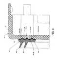
- FIG. 6is a cross section view along line 6 - 6 of FIG. 1 ;
- FIG. 7is a cross section view along line 7 - 7 of FIG. 1 ;
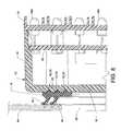
- FIG. 8is cross section view showing the use of the present invention in an intimate flexed sealing engagement about an opening of a mounting panel of an electronic sign showing the mode of operation of the present invention.
- FIG. 1is a rear isometric view of a an electronic sign module housing having an overmolded gasket seal 10 , the present invention, including an electronic sign module housing 12 and an overmolded gasket seal 14 attached thereto.
- the housing 12 of the present inventionis closely related to and is constructed according to the teachings and principals of the housing and can be incorporated into use with other components and features of the previously referenced U.S. Pat. No. 7,055,271 entitled “Electronic Display Module Having a Four-point Latching System for Incorporation into an Electronic Sign and Process”.
- U.S. Pat. No. 7,055,271entitled “Electronic Display Module Having a Four-point Latching System for Incorporation into an Electronic Sign and Process”.
- 7,055,271include a peripheral wall 16 , a configured panel 18 , a louver panel 24 at the front of the electronic sign module housing 12 , actuator arms 28 a - 28 d , and locator posts 30 a - 30 d .
- the overmolded gasket seal 14 in combination with the geometrically configured features of the panel 18adds functionality to the electronic sign module housing 12 by providing a fixed-in-place overmolded gasket seal 14 which requires minimum alignment skills of an assembler when the electronic sign module housing 12 , including the overmolded gasket seal 14 , is mated with the front panel of an electronic sign enclosure.
- FIG. 2is a semi-exploded rear isometric view of the electronic sign module housing having an overmolded gasket seal 10 showing the overmolded gasket seal 14 distanced from the panel 18 of the electronic sign module housing 12 .
- FIG. 3is an exploded view of a section of an upper corner of the electronic sign module housing 12 and a section of the overmolded gasket seal 14 spaced therefrom.
- Distancing of the overmolded gasket seal 14 from the electronic sign module housing 12reveals a plurality of continuously spaced concentrically arranged inner, middle and outer elongated arcuate grooves 32 , 34 and 36 , the paths of which generally are in the shape of rectangles having rounded corners.
- the inner, middle and outer arcuate grooves 32 , 34 and 36extend through and below the rear planar surface of and a short distance into the panel 18 and are located within an outline encompassing an interrupted contact surface 38 of the panel 18 .
- the arcuate groovesare aligned with features of the overmolded gasket seal 14 and which arcuate grooves are shown and bounded by dashed lines 20 and 22 superimposed on the panel 18 .
- a plurality of truncated conical cavities 40 a - 40 nis located along and about and extend through the contact surface 38 and into the panel 18 .
- the truncated conical cavities 40 a - 40 nact in concert with the overmolding features to capture material comprising the overmolded gasket seal 14 in order to assist in anchoring it to the electronic sign module housing 12 , as later described in detail.
- the truncated conical cavities 40 a - 40 nare aligned in various locations along the contact surface 38 and extend through the panel 18 in order to provide a widely based and uniform distribution of the truncated conical cavities 40 a - 40 n and to communicate with a plurality of truncated conical projections 42 a - 42 nn which extend from the front side of the overmolded gasket seal 14 and which flow into the plurality of truncated conical cavities 40 a - 40 n during the molding process.
- Other visible parts of the continuous overmolded gasket seal 14include a continuous base 44 and a continuously spaced concentrically arranged parallel compliant flexible inner lip 46 and an outer lip 48 , as further described in FIG. 4 .
- the overmolded gasket seal 14is formed of a flexible compliant material, such as, but not limited to, a thermoplastic elastomer (TPE) or other such material, such as described later in detail.
- TPEthermoplastic elastomer
- FIG. 4is a section view generally along a combined section line 4 ab - 4 ab of FIG. 1 , but more specifically is shown in greater detail along corresponding section lines 4 a - 4 a and 4 b - 4 b of FIG. 3 where the overmolded gasket seal 14 , such as formed by overmolding, is shown spaced from the electronic sign module housing 12 .
- the arcuate grooves 32 , 34 and 36are shown extending through the contact surface 38 and into the panel 18 of the electronic sign module housing 12 . The use of arcuate grooves of 180° or less is friendly to overmolding bonding.
- arcuate groovescan be used which are suitable for bonding and which can also enhance communication and frictional engagement between the overmolded gasket seal 14 and the electronic sign module housing 12 .
- the arcuate structure for the inner, middle and outer arcuate grooves 32 , 34 and 36can exceed 180° by a suitable arcuate dimension in order to provide a physical frictional engagement of the injected gasket seal material, as well as providing a chemically bonded overmold engagement between the overmolded gasket seal 14 and the electronic sign module housing 12 .
- groove-like structurescould also be used including, but not limited to, a square groove, an inverted T-groove, a truncated triangular groove, or other suitable geometric shapes conducive to bonding, capturing or captured bonding and the like.
- truncated conical cavities 40 a - 40 nare also beneficial.
- the truncated conical cavities 40 a - 40 nare tapered and accept inflow of molding material, thereby forming the truncated conical projections 42 a - 42 nn extending from the overmold gasket seal 14 in order to provide a physical frictional attachment, as well as a chemically bonded overmold engagement with the truncated conical cavities 40 a - 40 n and the truncated conical projections 42 a - 42 nn between the overmolded gasket seal 14 and the electronic sign module housing 12 .
- the overmolded gasket seal 14is shaped by in-place molding by methods known in the art to form and cause chemical bonding of material comprising the overmolded gasket seal 14 and the features thereof to the electronic sign module housing 12 , as well as providing captured physical frictional engagement therebetween.
- the overmolded gasket seal 14assumes the exterior mold shape and the immediate shape of the structure to which overmolding takes place, whereby a plurality of geometrically shaped features are resultantly formed, such as now described herein, as separate features for the sake of clarity and demonstration, i.e., the overmolded gasket seal 14 is described such as it would appear subsequent to overmolding and removed from intimate contact with the electronic sign module housing 12 .
- the overmolded gasket seal 14includes the flexible inner lip 46 and the flexible outer lip 48 each extending at an angle from the base 44 in order that flexing of the inner lip 46 and the outer lip 48 can conformingly provide a seal between the front panel of an electronic sign enclosure when engaged thereto under slight pressure.
- a planar surface 50is located on the front side of the base 44 and is interrupted by the previously described plurality of truncated conical projections 42 a - 42 n extending forwardly from the base 44 .
- the planar surface 50is also interrupted by a plurality of continuously spaced concentrically arranged inner, middle and outer elongated arcuate projections 52 , 54 and 56 , the paths of which generally are in the shape and form of rectangles having rounded corners extending forwardly from the base 44 .
- Other geometrically configured shapessuch as, but not limited to, those which would be conformingly and correspondingly accommodated by the alternative shapes of previously described geometrically configured groove-like structures for the inner, middle and outer arcuate grooves 32 , 34 and 36 can also be used in lieu of the inner, middle and outer elongated arcuate projections 52 , 54 and 56 .
- FIG. 5is similar to FIG. 4 where the overmolded gasket seal 14 is bonded to the electronic sign module housing 12 by an overmolding process.
- the cross sectionextends through the base 44 , through the inner lip 46 and outer lip 48 , through the planar surface 50 , through the inner, middle and outer elongated arcuate projections 52 , 54 and 56 , and through the truncated conical projection 42 a of the overmolded gasket seal 14 .
- the cross sectionalso extends through the peripheral wall 16 , the panel 18 , the truncated conical cavity 40 a , the inner, middle and outer arcuate grooves 32 , 34 and 36 , and the contact surface 38 of the electronic sign module housing 12 .
- Overmoldingis the process where two parts, a substrate and an overmold, are joined together to make a final product.
- the substrateis the electronic sign module housing 12 which is made in a first injection mold tool and which consists of hard and rigid plastic.
- the electronic sign module housing 12is removed from the first injection mold tool and then placed in a second mold, i.e., an overmold tool, where a thermoplastic elastomer (TPE) material, such as Versaflex® by GLS Corporation of McHenry, Ill., or other suitable material, such as, but not limited to, Tekbond® by Teknor Apex Company of Pawtucket, R.I., is applied by injection molding to form the overmolded gasket seal 14 which forms a chemical bond with the electronic sign module housing 12 .
- TPEthermoplastic elastomer
- the overmold toolis tooled to precisely fit the electronic sign module housing 12 in it, i.e., the substrate, and allow for application of TPE overmold material, i.e., the overmold therein and thereupon.
- the overmold and the substrate, i.e., the thermoplastic elastomer of the overmolded gasket seal 14 and the plastic material of the electronic sign module housing 12form a continuous chemical bond 58 where the combined surface 50 of the overmolded gasket seal 14 which is uninterrupted by the inner, middle and outer arcuate projections 52 , 54 and 56 and the inner, middle and outer arcuate projections 52 , 54 and 56 and which interrupt the surface 50 comprise a portion of the continuous chemical bond 58 and the combined contact surface 38 of the electronic sign module housing 12 which is uninterrupted by the inner, middle and outer arcuate grooves 32 , 34 and 36 and the inner, middle and outer arcuate grooves 32 , 34 and 36 and which interrupt the contact surface 38 comprise another portion of a continuous chemical bond 58 .
- the use of and relationship of the inner, middle and outer arcuate grooves 32 , 34 and 36is such that an additional bonding surface is provided extending through the contact surface 38 and into the panel 18 by the inner, middle and outer arcuate grooves 32 , 34 and 36 of the substrate electronic sign module housing 12 and which grooves correspondingly interface with the inner, middle and outer arcuate projections 52 , 54 and 56 and the planar surface 50 of the overmolded gasket seal 14 .
- the chemical bond 58 along the contact surface 38 , the inner, middle and outer arcuate grooves 32 , 34 and 36 , the planar surface 50 and the inner, middle and outer arcuate projections 52 , 54 and 56provides for a suitable attachment of the overmolded gasket seal 14 to the electronic sign module housing 12 by the merits of the chemical bond 58 . Additionally, protection against a shearing force is provided by the geometric physical shapes of the inner, middle and outer arcuate projections 52 , 54 and 56 of the overmolded gasket seal 14 extending into the inner, middle and outer arcuate grooves 32 , 34 and 36 of the electronic sign module housing 12 .
- the physical geometric relationship of the inner, middle and outer arcuate projections 52 , 54 and 56 extending into the inner, middle and outer arcuate grooves 32 , 34 and 36would prevent horizontal displacement of the overmolded gasket seal 14 across and along the electronic sign module housing 12 .
- the specified temperature range for suitable use exposure and of the thermoplastic elastomer of the overmolded gasket seal 14 in combination with the electronic sign module housing 12 forming an electronic sign module housing having an overmolded gasket seal 10is 120° F. to ⁇ 20° F., thereby allowing use over a broad temperature range.
- FIG. 6is a cross section view along line 6 - 6 of FIG. 1 .
- the cross sectionextends through the base 44 , through the inner lip 46 and outer lip 48 , through the planar surface 50 , and through the inner, middle and outer elongated arcuate projections 52 , 54 and 56 .
- the cross sectionextends through the peripheral wall 16 , the panel 18 , and the inner, middle and outer arcuate grooves 32 , 34 and 36 .
- FIG. 7is a cross section view along line 7 - 7 of FIG. 1 showing the relationship of the overmold gasket seal 14 to the electronic sign module housing 12 .
- FIG. 8is a cross section view showing the use of the present invention in an intimate, flexed, sealing engagement about an opening 62 of a mounting panel 64 of an electronic sign. More specifically, the electronic sign module housing 12 is positioned in close proximity and secured to the mounting panel 64 , such as described in the referenced U.S. Pat. No. 7,055,271, in order to cause a flexed engagement of the inner lip 46 and the outer lip 48 with the mounting panel 64 and to provide a seal about the opening 62 . The unflexed position of the inner lip 46 and the outer lip 48 is shown in dashed lines. Also shown as parts of an electronic sign are an LED display panel 66 having a plurality of LEDs 68 a - 68 n attached thereto and a louver panel 70 .
- PARTS LIST 10 electronic sign module housinghaving an overmolded gasket seal 12 electronic sign module housing 14 overmolded gasket seal 16 peripheral wall 18 panel 20 dashed line 22 dashed line 24 louver panel 26a-d latch mechanisms 28a-d actuator arms 30a-d located posts 32 inner arcuate groove 34 middle arcuate groove 36 outer arcuate groove 38 contact surface 40a-nn truncated conical cavities 42a-nn truncated conical projections 44 base 46 inner lip 48 outer lip 50 planar surface 52 inner arcuate projection 54 middle arcuate projection 56 outer arcuate projection 58 chemical bond 60 chemical bond 62 opening 64 mounting panel 66 LED panel 68a-n LEDs 70 louver panel
Landscapes
- Engineering & Computer Science (AREA)
- Mechanical Engineering (AREA)
- General Engineering & Computer Science (AREA)
- Physics & Mathematics (AREA)
- General Physics & Mathematics (AREA)
- Theoretical Computer Science (AREA)
- Manufacturing & Machinery (AREA)
- Microelectronics & Electronic Packaging (AREA)
- Casings For Electric Apparatus (AREA)
Abstract
Description
| 10 | electronic sign module housing having an | ||
| 12 | electronic | ||
| 14 | |||
| 16 | |||
| 18 | |||
| 20 | dashed | ||
| 22 | dashed | ||
| 24 | |||
| 26a- | latch mechanisms | ||
| 28a- | actuator arms | ||
| 30a-d | located posts | ||
| 32 | inner | ||
| 34 | middle | ||
| 36 | outer | ||
| 38 | |||
| 40a-nn | truncated | ||
| 42a-nn | truncated | ||
| 44 | |||
| 46 | |||
| 48 | |||
| 50 | |||
| 52 | inner | ||
| 54 | middle | ||
| 56 | outer | ||
| 58 | |||
| 60 | |||
| 62 | |||
| 64 | mounting | ||
| 66 | |||
| 68a- | LEDs | ||
| 70 | louver panel | ||
Claims (26)
Priority Applications (1)
| Application Number | Priority Date | Filing Date | Title |
|---|---|---|---|
| US12/220,825US8136279B1 (en) | 2007-07-31 | 2008-07-29 | Electronic sign module housing having an overmolded gasket seal |
Applications Claiming Priority (2)
| Application Number | Priority Date | Filing Date | Title |
|---|---|---|---|
| US96273207P | 2007-07-31 | 2007-07-31 | |
| US12/220,825US8136279B1 (en) | 2007-07-31 | 2008-07-29 | Electronic sign module housing having an overmolded gasket seal |
Publications (1)
| Publication Number | Publication Date |
|---|---|
| US8136279B1true US8136279B1 (en) | 2012-03-20 |
Family
ID=45813240
Family Applications (1)
| Application Number | Title | Priority Date | Filing Date |
|---|---|---|---|
| US12/220,825Expired - Fee RelatedUS8136279B1 (en) | 2007-07-31 | 2008-07-29 | Electronic sign module housing having an overmolded gasket seal |
Country Status (1)
| Country | Link |
|---|---|
| US (1) | US8136279B1 (en) |
Cited By (24)
| Publication number | Priority date | Publication date | Assignee | Title |
|---|---|---|---|---|
| US20110229666A1 (en)* | 2010-03-16 | 2011-09-22 | Alps Electric Co., Ltd. | Injection-molded body |
| US8528264B1 (en) | 2011-01-20 | 2013-09-10 | Pepperl+Fuchs Gmbh | Wall mount human machine interface |
| EP2642624A1 (en)* | 2012-03-22 | 2013-09-25 | Tyco Electronics Belgium EC BVBA | Compressed over-molded seal for insulated cables |
| US20140153241A1 (en)* | 2012-12-01 | 2014-06-05 | Lsi Industries, Inc. | Display board and display board components |
| GB2520573A (en)* | 2013-11-26 | 2015-05-27 | Michael John Fenner | A ring seal and flange clamping system |
| US9069519B1 (en) | 2013-12-31 | 2015-06-30 | Ultravision Technologies, Llc | Power and control system for modular multi-panel display system |
| US9164722B2 (en) | 2013-12-31 | 2015-10-20 | Ultravision Technologies, Llc | Modular display panels with different pitches |
| US9207904B2 (en) | 2013-12-31 | 2015-12-08 | Ultravision Technologies, Llc | Multi-panel display with hot swappable display panels and methods of servicing thereof |
| US20160057878A1 (en)* | 2014-08-25 | 2016-02-25 | Wistron Corporation | Protective Structure and Electronic Device Thereof |
| US9311847B2 (en) | 2014-07-16 | 2016-04-12 | Ultravision Technologies, Llc | Display system having monitoring circuit and methods thereof |
| WO2016105223A1 (en)* | 2014-12-23 | 2016-06-30 | Valeo Autosystemy Sp. Z O.O. | Seal for sealing off the gap between a heat exchanger and the inside wall of a groove in a fluid channel |
| US9416551B2 (en) | 2013-12-31 | 2016-08-16 | Ultravision Technologies, Llc | Preassembled display systems and methods of installation thereof |
| US9455560B1 (en) | 2013-10-11 | 2016-09-27 | Pepperl+Fuchs, Inc. | Closure seal method and apparatus for wall mount enclosure |
| US20170178854A1 (en)* | 2015-12-18 | 2017-06-22 | Abb Schweiz Ag | Pressure Resistant Housing For Subsea Applications |
| US10061553B2 (en) | 2013-12-31 | 2018-08-28 | Ultravision Technologies, Llc | Power and data communication arrangement between panels |
| US20190053394A1 (en)* | 2017-08-10 | 2019-02-14 | Fanuc Corporation | Electronic device mounted to an industrial machine |
| WO2019202168A1 (en) | 2018-04-19 | 2019-10-24 | Hachadorian Design & Calculation Gmbh | Electrical connector with cam controlled locking device |
| US10549561B2 (en) | 2017-05-04 | 2020-02-04 | Datamax-O'neil Corporation | Apparatus for sealing an enclosure |
| US10760331B2 (en)* | 2015-04-24 | 2020-09-01 | Quick Fix Solutions, Inc | Sealing device and method of installation |
| US10891881B2 (en) | 2012-07-30 | 2021-01-12 | Ultravision Technologies, Llc | Lighting assembly with LEDs and optical elements |
| US20220412478A1 (en)* | 2021-06-25 | 2022-12-29 | Nidec Tosok Corporation | Solenoid valve |
| USD999346S1 (en)* | 2019-11-22 | 2023-09-19 | Transportation Ip Holdings, Llc | Seal structure of a body |
| US20230417032A1 (en)* | 2021-06-23 | 2023-12-28 | PlungeAway, LLC | Plunger assembly |
| US20240206098A1 (en)* | 2021-03-19 | 2024-06-20 | Efla Oy | A casing and a method for encapsulation using injection moulding |
Citations (17)
| Publication number | Priority date | Publication date | Assignee | Title |
|---|---|---|---|---|
| US2053547A (en) | 1935-10-09 | 1936-09-08 | Gen Motors Truck Corp | Baggage door lock |
| US3403717A (en)* | 1966-02-14 | 1968-10-01 | Jerome H. Lemelson | Sealing and bonding device |
| US3594761A (en) | 1969-01-29 | 1971-07-20 | Stewart Warner Corp | Information display module |
| US4234914A (en) | 1979-03-13 | 1980-11-18 | Stewart-Warner Corporation | Incandescent display system |
| US5172504A (en) | 1991-02-08 | 1992-12-22 | Grid-Graphics Services Corporation | Front-mount grid display having trim strips and hook and loop |
| US5268828A (en) | 1991-04-19 | 1993-12-07 | Takiron Co., Ltd. | Illuminant display device |
| US5647152A (en) | 1994-03-18 | 1997-07-15 | Takiron Co., Ltd. | Displaying apparatus with light-shielding grating |
| US5692855A (en) | 1994-06-21 | 1997-12-02 | Farmers' Factory Co. | Automatic quick-connect coupler for implements |
| US5715619A (en) | 1995-02-15 | 1998-02-10 | Groupe Infocite Inc. | Information display sign |
| US6154945A (en) | 1998-08-26 | 2000-12-05 | Daktronics, Inc. | Process for removing a sign display module |
| US6314669B1 (en) | 1999-02-09 | 2001-11-13 | Daktronics, Inc. | Sectional display system |
| US6508494B1 (en) | 1999-09-29 | 2003-01-21 | Rittal-Werk Rudolf Loh Gmbh & Co. Kg | Locking arrangement for a switchgear cabinet |
| US20030217495A1 (en) | 2002-05-24 | 2003-11-27 | Toshiba Transport Engineering Inc. | Unit connecting mechanism and image display device |
| US6729054B1 (en) | 2001-12-19 | 2004-05-04 | Daktronics, Inc. | Articulated continuous electronic display |
| US6832444B1 (en)* | 2002-05-17 | 2004-12-21 | Macneil David F. | Vehicle license plate cover with decorative insert |
| US20050152139A1 (en)* | 1996-10-22 | 2005-07-14 | Loving David S. | Process for making lighted fiberglass panels |
| US7055271B2 (en) | 2003-10-17 | 2006-06-06 | Daktronics, Inc. | Electronic display module having a four-point latching system for incorporation into an electronic sign and process |
- 2008
- 2008-07-29USUS12/220,825patent/US8136279B1/ennot_activeExpired - Fee Related
Patent Citations (17)
| Publication number | Priority date | Publication date | Assignee | Title |
|---|---|---|---|---|
| US2053547A (en) | 1935-10-09 | 1936-09-08 | Gen Motors Truck Corp | Baggage door lock |
| US3403717A (en)* | 1966-02-14 | 1968-10-01 | Jerome H. Lemelson | Sealing and bonding device |
| US3594761A (en) | 1969-01-29 | 1971-07-20 | Stewart Warner Corp | Information display module |
| US4234914A (en) | 1979-03-13 | 1980-11-18 | Stewart-Warner Corporation | Incandescent display system |
| US5172504A (en) | 1991-02-08 | 1992-12-22 | Grid-Graphics Services Corporation | Front-mount grid display having trim strips and hook and loop |
| US5268828A (en) | 1991-04-19 | 1993-12-07 | Takiron Co., Ltd. | Illuminant display device |
| US5647152A (en) | 1994-03-18 | 1997-07-15 | Takiron Co., Ltd. | Displaying apparatus with light-shielding grating |
| US5692855A (en) | 1994-06-21 | 1997-12-02 | Farmers' Factory Co. | Automatic quick-connect coupler for implements |
| US5715619A (en) | 1995-02-15 | 1998-02-10 | Groupe Infocite Inc. | Information display sign |
| US20050152139A1 (en)* | 1996-10-22 | 2005-07-14 | Loving David S. | Process for making lighted fiberglass panels |
| US6154945A (en) | 1998-08-26 | 2000-12-05 | Daktronics, Inc. | Process for removing a sign display module |
| US6314669B1 (en) | 1999-02-09 | 2001-11-13 | Daktronics, Inc. | Sectional display system |
| US6508494B1 (en) | 1999-09-29 | 2003-01-21 | Rittal-Werk Rudolf Loh Gmbh & Co. Kg | Locking arrangement for a switchgear cabinet |
| US6729054B1 (en) | 2001-12-19 | 2004-05-04 | Daktronics, Inc. | Articulated continuous electronic display |
| US6832444B1 (en)* | 2002-05-17 | 2004-12-21 | Macneil David F. | Vehicle license plate cover with decorative insert |
| US20030217495A1 (en) | 2002-05-24 | 2003-11-27 | Toshiba Transport Engineering Inc. | Unit connecting mechanism and image display device |
| US7055271B2 (en) | 2003-10-17 | 2006-06-06 | Daktronics, Inc. | Electronic display module having a four-point latching system for incorporation into an electronic sign and process |
Non-Patent Citations (5)
Cited By (57)
| Publication number | Priority date | Publication date | Assignee | Title |
|---|---|---|---|---|
| US8252395B2 (en)* | 2010-03-16 | 2012-08-28 | Alps Electric Co., Ltd. | Injection-molded body |
| US20110229666A1 (en)* | 2010-03-16 | 2011-09-22 | Alps Electric Co., Ltd. | Injection-molded body |
| US8528264B1 (en) | 2011-01-20 | 2013-09-10 | Pepperl+Fuchs Gmbh | Wall mount human machine interface |
| US8782961B1 (en) | 2011-01-20 | 2014-07-22 | Pepperl+Fuchs, Inc. | Wall mount human machine interface |
| US8839567B1 (en) | 2011-01-20 | 2014-09-23 | Pepperl+Fuchs, Inc. | Wall mount human machine interface |
| EP2642624A1 (en)* | 2012-03-22 | 2013-09-25 | Tyco Electronics Belgium EC BVBA | Compressed over-molded seal for insulated cables |
| US10891881B2 (en) | 2012-07-30 | 2021-01-12 | Ultravision Technologies, Llc | Lighting assembly with LEDs and optical elements |
| US20140153241A1 (en)* | 2012-12-01 | 2014-06-05 | Lsi Industries, Inc. | Display board and display board components |
| US9455560B1 (en) | 2013-10-11 | 2016-09-27 | Pepperl+Fuchs, Inc. | Closure seal method and apparatus for wall mount enclosure |
| GB2520573A (en)* | 2013-11-26 | 2015-05-27 | Michael John Fenner | A ring seal and flange clamping system |
| US9416551B2 (en) | 2013-12-31 | 2016-08-16 | Ultravision Technologies, Llc | Preassembled display systems and methods of installation thereof |
| US9582237B2 (en) | 2013-12-31 | 2017-02-28 | Ultravision Technologies, Llc | Modular display panels with different pitches |
| US9195281B2 (en) | 2013-12-31 | 2015-11-24 | Ultravision Technologies, Llc | System and method for a modular multi-panel display |
| US9207904B2 (en) | 2013-12-31 | 2015-12-08 | Ultravision Technologies, Llc | Multi-panel display with hot swappable display panels and methods of servicing thereof |
| US9226413B1 (en) | 2013-12-31 | 2015-12-29 | Ultravision Technologies, Llc | Integrated data and power cord for use with modular display panels |
| US10540917B2 (en) | 2013-12-31 | 2020-01-21 | Ultravision Technologies, Llc | Modular display panel |
| US10380925B2 (en) | 2013-12-31 | 2019-08-13 | Ultravision Technologies, Llc | Modular display panel |
| US9349306B2 (en) | 2013-12-31 | 2016-05-24 | Ultravision Technologies, Llc | Modular display panel |
| US9372659B2 (en) | 2013-12-31 | 2016-06-21 | Ultravision Technologies, Llc | Modular multi-panel display system using integrated data and power cables |
| US9134773B2 (en) | 2013-12-31 | 2015-09-15 | Ultravision Technologies, Llc | Modular display panel |
| US10410552B2 (en) | 2013-12-31 | 2019-09-10 | Ultravision Technologies, Llc | Modular display panel |
| US9081552B1 (en) | 2013-12-31 | 2015-07-14 | Ultravision Technologies, Llc | Integrated data and power cord for use with modular display panels |
| US9513863B2 (en) | 2013-12-31 | 2016-12-06 | Ultravision Technologies, Llc | Modular display panel |
| US9528283B2 (en) | 2013-12-31 | 2016-12-27 | Ultravision Technologies, Llc | Method of performing an installation of a display unit |
| US9535650B2 (en) | 2013-12-31 | 2017-01-03 | Ultravision Technologies, Llc | System for modular multi-panel display wherein each display is sealed to be waterproof and includes array of display elements arranged to form display panel surface |
| US9164722B2 (en) | 2013-12-31 | 2015-10-20 | Ultravision Technologies, Llc | Modular display panels with different pitches |
| US9642272B1 (en) | 2013-12-31 | 2017-05-02 | Ultravision Technologies, Llc | Method for modular multi-panel display wherein each display is sealed to be waterproof and includes array of display elements arranged to form display panel surface |
| US10871932B2 (en) | 2013-12-31 | 2020-12-22 | Ultravision Technologies, Llc | Modular display panels |
| US9832897B2 (en) | 2013-12-31 | 2017-11-28 | Ultravision Technologies, Llc | Method of assembling a modular multi-panel display system |
| US9069519B1 (en) | 2013-12-31 | 2015-06-30 | Ultravision Technologies, Llc | Power and control system for modular multi-panel display system |
| US9916782B2 (en) | 2013-12-31 | 2018-03-13 | Ultravision Technologies, Llc | Modular display panel |
| US9940856B2 (en) | 2013-12-31 | 2018-04-10 | Ultravision Technologies, Llc | Preassembled display systems and methods of installation thereof |
| US9978294B1 (en) | 2013-12-31 | 2018-05-22 | Ultravision Technologies, Llc | Modular display panel |
| US9984603B1 (en) | 2013-12-31 | 2018-05-29 | Ultravision Technologies, Llc | Modular display panel |
| US9990869B1 (en) | 2013-12-31 | 2018-06-05 | Ultravision Technologies, Llc | Modular display panel |
| US10061553B2 (en) | 2013-12-31 | 2018-08-28 | Ultravision Technologies, Llc | Power and data communication arrangement between panels |
| US10741107B2 (en) | 2013-12-31 | 2020-08-11 | Ultravision Technologies, Llc | Modular display panel |
| US10373535B2 (en) | 2013-12-31 | 2019-08-06 | Ultravision Technologies, Llc | Modular display panel |
| US10248372B2 (en) | 2013-12-31 | 2019-04-02 | Ultravision Technologies, Llc | Modular display panels |
| US10706770B2 (en) | 2014-07-16 | 2020-07-07 | Ultravision Technologies, Llc | Display system having module display panel with circuitry for bidirectional communication |
| US9311847B2 (en) | 2014-07-16 | 2016-04-12 | Ultravision Technologies, Llc | Display system having monitoring circuit and methods thereof |
| US20160057878A1 (en)* | 2014-08-25 | 2016-02-25 | Wistron Corporation | Protective Structure and Electronic Device Thereof |
| CN107532501A (en)* | 2014-12-23 | 2018-01-02 | 法雷奥自动系统公司 | Seal for the gap between the inwall for the groove being sealed in heat exchanger and fluid passage |
| CN107532501B (en)* | 2014-12-23 | 2020-06-26 | 法雷奥自动系统公司 | Seal for sealing a gap between a heat exchanger and an inner wall of a groove in a fluid channel |
| WO2016105223A1 (en)* | 2014-12-23 | 2016-06-30 | Valeo Autosystemy Sp. Z O.O. | Seal for sealing off the gap between a heat exchanger and the inside wall of a groove in a fluid channel |
| US10760331B2 (en)* | 2015-04-24 | 2020-09-01 | Quick Fix Solutions, Inc | Sealing device and method of installation |
| US10109445B2 (en)* | 2015-12-18 | 2018-10-23 | Abb Schweiz Ag | Pressure resistant housing for subsea applications |
| US20170178854A1 (en)* | 2015-12-18 | 2017-06-22 | Abb Schweiz Ag | Pressure Resistant Housing For Subsea Applications |
| US10549561B2 (en) | 2017-05-04 | 2020-02-04 | Datamax-O'neil Corporation | Apparatus for sealing an enclosure |
| US20190053394A1 (en)* | 2017-08-10 | 2019-02-14 | Fanuc Corporation | Electronic device mounted to an industrial machine |
| US10412847B2 (en)* | 2017-08-10 | 2019-09-10 | Fanuc Corporation | Electronic device mounted to an industrial machine |
| WO2019202168A1 (en) | 2018-04-19 | 2019-10-24 | Hachadorian Design & Calculation Gmbh | Electrical connector with cam controlled locking device |
| USD999346S1 (en)* | 2019-11-22 | 2023-09-19 | Transportation Ip Holdings, Llc | Seal structure of a body |
| US20240206098A1 (en)* | 2021-03-19 | 2024-06-20 | Efla Oy | A casing and a method for encapsulation using injection moulding |
| US20230417032A1 (en)* | 2021-06-23 | 2023-12-28 | PlungeAway, LLC | Plunger assembly |
| US20220412478A1 (en)* | 2021-06-25 | 2022-12-29 | Nidec Tosok Corporation | Solenoid valve |
| US11976739B2 (en)* | 2021-06-25 | 2024-05-07 | Nidec Tosok Corporation | Solenoid valve |
Similar Documents
| Publication | Publication Date | Title |
|---|---|---|
| US8136279B1 (en) | Electronic sign module housing having an overmolded gasket seal | |
| US8025530B2 (en) | Method and apparatus involving a housing with a sealed electrical connector | |
| US10368456B2 (en) | Low closure force gasket | |
| US20120068586A1 (en) | Enclosure Corner Seals and Assemblies | |
| GB2450267A (en) | Load bearing assembly with elastomeric edge | |
| EP2053907A3 (en) | Method of producing an overmolded electronic module with a flexible circuit pigtail | |
| CN101952132A (en) | Encapsulated window assembly with integral seal and method of installing same | |
| CN113696819B (en) | Side window edge covering mechanism, side window edge covering glass assembly and automobile | |
| JP2012054929A (en) | Image display device | |
| US20140374580A1 (en) | Multi-Optical Axis Photoelectric Sensor | |
| US12185632B2 (en) | Mechanical integration of buttons for piezo-electric actuators | |
| JP2018505531A (en) | LED module | |
| US10211873B2 (en) | Mobile terminal and rear housing for mobile terminal | |
| BR102016019448B1 (en) | VISUALIZATION SYSTEM FOR VEHICLES | |
| CN101325316B (en) | Operation panel with sealed structure | |
| JP2015105497A (en) | Corner part parting member | |
| JP2009144765A (en) | Seal packing | |
| CN106065755A (en) | Corner connectors for glass fixing trim | |
| KR101872453B1 (en) | Bolt-type Locking Structure for LED Lamp Housing and Method of Installing the Same | |
| KR20190000883U (en) | The Structure of Window to be Fixed | |
| CN208093404U (en) | A kind of function button structure and the hand-held thermal infrared imager with it | |
| CN108710239B (en) | Backlight module | |
| JP2008083562A (en) | Display device | |
| TWI760863B (en) | Anti loosening structure, frame structure and backlight module | |
| CN221466215U (en) | LED display module and LED display device with same |
Legal Events
| Date | Code | Title | Description |
|---|---|---|---|
| AS | Assignment | Owner name:DAKTRONICS, INC., SOUTH DAKOTA Free format text:ASSIGNMENT OF ASSIGNORS INTEREST;ASSIGNORS:NEARMAN, NATHAN L.;KLUDT, KORY D.;SIGNING DATES FROM 20080718 TO 20080723;REEL/FRAME:021361/0297 | |
| ZAAA | Notice of allowance and fees due | Free format text:ORIGINAL CODE: NOA | |
| ZAAB | Notice of allowance mailed | Free format text:ORIGINAL CODE: MN/=. | |
| FEPP | Fee payment procedure | Free format text:PAYOR NUMBER ASSIGNED (ORIGINAL EVENT CODE: ASPN); ENTITY STATUS OF PATENT OWNER: LARGE ENTITY | |
| STCF | Information on status: patent grant | Free format text:PATENTED CASE | |
| FPAY | Fee payment | Year of fee payment:4 | |
| MAFP | Maintenance fee payment | Free format text:PAYMENT OF MAINTENANCE FEE, 8TH YEAR, LARGE ENTITY (ORIGINAL EVENT CODE: M1552); ENTITY STATUS OF PATENT OWNER: LARGE ENTITY Year of fee payment:8 | |
| AS | Assignment | Owner name:JPMORGAN CHASE BANK, N.A., AS ADMINISTRATIVE AGENT, ILLINOIS Free format text:SECURITY INTEREST;ASSIGNOR:DAKTRONICS, INC.;REEL/FRAME:063622/0039 Effective date:20230511 | |
| FEPP | Fee payment procedure | Free format text:MAINTENANCE FEE REMINDER MAILED (ORIGINAL EVENT CODE: REM.); ENTITY STATUS OF PATENT OWNER: LARGE ENTITY | |
| LAPS | Lapse for failure to pay maintenance fees | Free format text:PATENT EXPIRED FOR FAILURE TO PAY MAINTENANCE FEES (ORIGINAL EVENT CODE: EXP.); ENTITY STATUS OF PATENT OWNER: LARGE ENTITY | |
| STCH | Information on status: patent discontinuation | Free format text:PATENT EXPIRED DUE TO NONPAYMENT OF MAINTENANCE FEES UNDER 37 CFR 1.362 | |
| FP | Lapsed due to failure to pay maintenance fee | Effective date:20240320 |