US8136234B2 - Flaring coaxial cable end preparation tool and associated methods - Google Patents
Flaring coaxial cable end preparation tool and associated methodsDownload PDFInfo
- Publication number
- US8136234B2 US8136234B2US12/277,152US27715208AUS8136234B2US 8136234 B2US8136234 B2US 8136234B2US 27715208 AUS27715208 AUS 27715208AUS 8136234 B2US8136234 B2US 8136234B2
- Authority
- US
- United States
- Prior art keywords
- outer conductor
- projection
- coaxial cable
- cable
- preparation tool
- Prior art date
- Legal status (The legal status is an assumption and is not a legal conclusion. Google has not performed a legal analysis and makes no representation as to the accuracy of the status listed.)
- Expired - Fee Related, expires
Links
Images


Classifications
- H—ELECTRICITY
- H01—ELECTRIC ELEMENTS
- H01R—ELECTRICALLY-CONDUCTIVE CONNECTIONS; STRUCTURAL ASSOCIATIONS OF A PLURALITY OF MUTUALLY-INSULATED ELECTRICAL CONNECTING ELEMENTS; COUPLING DEVICES; CURRENT COLLECTORS
- H01R24/00—Two-part coupling devices, or either of their cooperating parts, characterised by their overall structure
- H01R24/38—Two-part coupling devices, or either of their cooperating parts, characterised by their overall structure having concentrically or coaxially arranged contacts
- H01R24/40—Two-part coupling devices, or either of their cooperating parts, characterised by their overall structure having concentrically or coaxially arranged contacts specially adapted for high frequency
- H—ELECTRICITY
- H01—ELECTRIC ELEMENTS
- H01R—ELECTRICALLY-CONDUCTIVE CONNECTIONS; STRUCTURAL ASSOCIATIONS OF A PLURALITY OF MUTUALLY-INSULATED ELECTRICAL CONNECTING ELEMENTS; COUPLING DEVICES; CURRENT COLLECTORS
- H01R43/00—Apparatus or processes specially adapted for manufacturing, assembling, maintaining, or repairing of line connectors or current collectors or for joining electric conductors
- H—ELECTRICITY
- H01—ELECTRIC ELEMENTS
- H01R—ELECTRICALLY-CONDUCTIVE CONNECTIONS; STRUCTURAL ASSOCIATIONS OF A PLURALITY OF MUTUALLY-INSULATED ELECTRICAL CONNECTING ELEMENTS; COUPLING DEVICES; CURRENT COLLECTORS
- H01R9/00—Structural associations of a plurality of mutually-insulated electrical connecting elements, e.g. terminal strips or terminal blocks; Terminals or binding posts mounted upon a base or in a case; Bases therefor
- H01R9/03—Connectors arranged to contact a plurality of the conductors of a multiconductor cable, e.g. tapping connections
- H01R9/05—Connectors arranged to contact a plurality of the conductors of a multiconductor cable, e.g. tapping connections for coaxial cables
- H—ELECTRICITY
- H01—ELECTRIC ELEMENTS
- H01R—ELECTRICALLY-CONDUCTIVE CONNECTIONS; STRUCTURAL ASSOCIATIONS OF A PLURALITY OF MUTUALLY-INSULATED ELECTRICAL CONNECTING ELEMENTS; COUPLING DEVICES; CURRENT COLLECTORS
- H01R2103/00—Two poles
- Y—GENERAL TAGGING OF NEW TECHNOLOGICAL DEVELOPMENTS; GENERAL TAGGING OF CROSS-SECTIONAL TECHNOLOGIES SPANNING OVER SEVERAL SECTIONS OF THE IPC; TECHNICAL SUBJECTS COVERED BY FORMER USPC CROSS-REFERENCE ART COLLECTIONS [XRACs] AND DIGESTS
- Y10—TECHNICAL SUBJECTS COVERED BY FORMER USPC
- Y10T—TECHNICAL SUBJECTS COVERED BY FORMER US CLASSIFICATION
- Y10T29/00—Metal working
- Y10T29/49—Method of mechanical manufacture
- Y10T29/49002—Electrical device making
- Y10T29/49117—Conductor or circuit manufacturing
- Y10T29/49123—Co-axial cable
- Y—GENERAL TAGGING OF NEW TECHNOLOGICAL DEVELOPMENTS; GENERAL TAGGING OF CROSS-SECTIONAL TECHNOLOGIES SPANNING OVER SEVERAL SECTIONS OF THE IPC; TECHNICAL SUBJECTS COVERED BY FORMER USPC CROSS-REFERENCE ART COLLECTIONS [XRACs] AND DIGESTS
- Y10—TECHNICAL SUBJECTS COVERED BY FORMER USPC
- Y10T—TECHNICAL SUBJECTS COVERED BY FORMER US CLASSIFICATION
- Y10T29/00—Metal working
- Y10T29/49—Method of mechanical manufacture
- Y10T29/49002—Electrical device making
- Y10T29/49117—Conductor or circuit manufacturing
- Y10T29/49174—Assembling terminal to elongated conductor
- Y10T29/49181—Assembling terminal to elongated conductor by deforming
- Y10T29/49185—Assembling terminal to elongated conductor by deforming of terminal
- Y10T29/49192—Assembling terminal to elongated conductor by deforming of terminal with insulation removal
- Y—GENERAL TAGGING OF NEW TECHNOLOGICAL DEVELOPMENTS; GENERAL TAGGING OF CROSS-SECTIONAL TECHNOLOGIES SPANNING OVER SEVERAL SECTIONS OF THE IPC; TECHNICAL SUBJECTS COVERED BY FORMER USPC CROSS-REFERENCE ART COLLECTIONS [XRACs] AND DIGESTS
- Y10—TECHNICAL SUBJECTS COVERED BY FORMER USPC
- Y10T—TECHNICAL SUBJECTS COVERED BY FORMER US CLASSIFICATION
- Y10T29/00—Metal working
- Y10T29/53—Means to assemble or disassemble
- Y10T29/5313—Means to assemble electrical device
- Y10T29/532—Conductor
- Y10T29/53209—Terminal or connector
- Y10T29/53213—Assembled to wire-type conductor
Definitions
- the present inventionrelates to the field of tools for the preparation of cable ends, and, more particularly, to tool for the preparation of coaxial cable ends and related methods.
- Coaxial cablesare widely used to carry high frequency electrical signals. Coaxial cables enjoy a relatively high bandwidth, low signal losses, are mechanically robust, and are relatively low cost.
- One particularly advantageous use of a coaxial cableis for connecting electronics at a cellular or wireless base station to an antenna mounted at the top of a nearby antenna tower.
- the transmitter located in an equipment sheltermay be connected to a transmit antenna supported by the antenna tower.
- the receiveris also connected to its associated receiver antenna by a coaxial cable path.
- a typical installationincludes a relatively large diameter coaxial cable extending between the equipment shelter and the top of the antenna tower to thereby reduce signal losses.
- Some coaxial cablesinclude a smooth outer conductor while other coaxial cables instead have a corrugated outer conductor.
- These coaxial cablesalso have an inner conductor and a dielectric between the outer conductor and the inner conductor.
- Some inner conductorsare hollow, while other inner conductors are formed around an inner conductor dielectric core.
- a typical connector for such a coaxial cableincludes a connector housing to make an electrical connection to the outer conductor and a center contact to make electrical connection to the inner conductor of the coaxial cable.
- Such a connectormay also include a back nut that is positioned onto the end of the outer conductor and adjacent the outer insulating jacket portion of the coaxial cable.
- Installation of coaxial cable connectorsgenerally requires that a technician cut and prepare the coaxial cable ends at the appropriate location to mount the connector thereon.
- the cable end preparationrequires removal of the outer jacket to expose a portion of the outer conductor, as well as removal of the outer conductor and dielectric layer to expose a portion of the inner conductor.
- the exposed portion of the outer conductormay also require flaring.
- performing these operationscan be difficult given the diameter of some coaxial cables, and the use of knives or other basic cutting tools with exposed blades may create a risk of injury to the technician.
- a technicianmay be required to install connectors while at the top a cell tower, which compounds the difficulties of preparing a cable end with basic cutting tools.
- U.S. Pat. No. 6,668,459 to Henningsendescribes stripping tools for coaxial cables with a corrugated outer conductor and a hollow inner conductor.
- the toolincludes three main parts: a jacket cutting part for removing a certain predetermined length of the jacket of the cable, a guide part to be placed around the end of the cable after the jacket has been removed by the jacket cutting part, and a second cutting part to be placed on the guide part during a final preparation of the end of the cable during which the inner conductor, the outer conductor and the dielectric material between inner and outer conductor are cut to appropriate lengths.
- the guide partis provided with a portion for determining a well-defined longitudinal position of the tool on the cable relative to the pattern of valleys and crests of the corrugation on the outer conductor.
- the flaring toolis for flaring the outer conductors of two different sizes of coaxial cable, and it includes a dome-shaped body and a reversible tool head.
- the tool headhas first and second shafts and first and second flaring heads on opposite sides. Reversing the tool head exposes the shaft and flaring head for the corresponding size of coaxial cable.
- the shaftsmatch the inner diameter of the inner conductor of the coaxial cable to be flared.
- the flaring headsare shaped as half cones, which allow the outer conductor to be flared without deforming the insulation between the inner and outer conductors of the coaxial cable.
- U.S. Pat. Pub. 2006/0112549 to Henningsendiscloses a tool for preparing the end of a coaxial cable.
- the toolcomprises an outer body with a cylindrical bore for receiving an end of the coaxial cable.
- the toolincludes a jacket removing member secured to the outer body and directed to the cylindrical bore for removing a portion of the jacket of the coaxial cable as the outer body is rotated relative to the coaxial cable.
- the toolalso includes a coring member for removing a portion of the dielectric surrounding the inner conductor as the outer body is rotated relative to the coaxial cable.
- a cable end preparation tool for a coaxial cablecomprising an inner conductor, an outer conductor, and a dielectric therebetween.
- the cable end preparation toolcomprises a body and a blade carried by the body for removing a portion of the dielectric between the inner conductor and the outer conductor when the body is rotated about the coaxial cable.
- a first projectionmay be carried by the body and may have a predetermined shape for flaring an end portion of the outer conductor when the body is rotated relative to the coaxial cable.
- the first projectionmay have an outwardly extending portion with a predetermined shape for beginning flaring of an end portion of the outer conductor when the body is rotated relative to the coaxial cable.
- the cable end preparation toolalso includes a second projection being movable with respect to the body between an outer conductor engaging position and a disengaged position.
- the second projectionis for corrugating the flared end portion of the outer conductor when in the outer conductor engaging position and the body is rotated relative to the coaxial cable. This corrugation may advantageously prepare a smooth wall coaxial cable to be used with connectors designed for use with corrugated coaxial cables.
- the second projectionmay comprise a base and a forming tip carried thereby.
- the basemay be pivotally connected to the body. This may advantageously allow the base to be pivoted to the disengaged position for use of the cable end preparation tool when corrugating the outer conductor of the cable is not desired.
- the bodymay have a disk shape.
- the bodymay have a central opening therein.
- a central rotation guidemay be carried by the body.
- the bodymay have first and second opposing sides.
- the blade and the first projectionmay be carried by the first side.
- the blademay be carried by the first side and the first projection may be carried by the second side.
- the bodymay have a blade access opening defined therein adjacent the cutting blade for receiving the portion of the dielectric between the inner conductor and the outer conductor removed by said cutting blade.
- the coaxial cablemay further comprise an adhesive layer between the outer conductor and the dielectric and the first projection may remove a portion of the adhesive layer when the body is rotated relative to the coaxial cable. Removal of the adhesive layer may provide for a better electrical contact between the outer conductor and a connector.
- the blade, first projection, and second projectionmay be removably mounted to the body.
- the bodymay have a gripping surface.
- the blade, the first projection, and the second projectionmay be integrally formed as a monolithic unit.
- Another aspectis directed to a method of preparing an end of a coaxial cable comprising an inner conductor, an outer conductor, and a dielectric therebetween, using a cable end preparation tool.
- the methodcomprises positioning the cable end preparation tool adjacent the coaxial cable end and removing a portion of the dielectric with a blade carried by a body of the cable end preparation tool by rotating the body relative to the coaxial cable. Further, the method includes flaring an end portion of the outer conductor with a first projection carried by the body by rotating the body relative to the coaxial cable.
- the methodincludes corrugating the flared end portion of the outer conductor with a second projection carried by the body and being movable with respect to the body between an outer conductor engaging position and a disengaged position by rotating the body relative to the coaxial cable when the second projection is in the outer conductor engaging position.
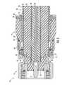
- FIG. 1is a perspective cutaway view of a connector installed on the end of a coaxial cable having a smooth outer conductor in accordance with the present invention.
- FIG. 2is a longitudinal cross-sectional view of the connector of FIG. 1 .
- FIG. 3is an exploded cross-sectional view of the connector of FIG. 1 .
- FIG. 4is an exploded view of the connector of FIG. 1 .
- FIG. 5is a perspective view of the back nut of FIG. 1 not installed on the end of the coaxial cable.
- FIG. 6is a greatly enlarged cross-sectional view of the compressible ring and ferrule of the connector of FIG. 1 .
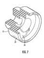
- FIG. 7is a perspective cutaway view of the insulator member of the connector of FIG. 1 .
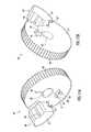
- FIG. 8is a perspective view of the rearward o-ring of the connector of FIG. 1 .
- FIG. 9is a perspective view of the ferrule of the connector of FIG. 1 .
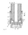
- FIG. 10is a longitudinal cross-sectional view of an alternative embodiment of a connector installed on the end of a coaxial cable having a corrugated outer conductor in accordance with the present invention.
- FIG. 11is a longitudinal cross-sectional view of yet another embodiment of a connector installed on the end of a coaxial cable having a smooth outer conductor in accordance with the present invention.
- FIG. 12is a perspective cutaway view of the connector of FIG. 11 .
- FIG. 13is a longitudinal cross-sectional view of a further embodiment of a connector installed on the end of a coaxial cable having a smooth outer conductor in accordance with the present invention.
- FIG. 14Ais front elevational view of a first embodiment of a cable preparation tool for a coaxial cable having a projection being in an outer conductor engaging position, in accordance with the present invention.
- FIG. 14Bis a front elevational view of the cable preparation tool of FIG. 14A with the projection in a disengaged position.
- FIG. 15Ais a front perspective view of an alternative embodiment of a cable preparation tool for a coaxial cable, in accordance with the present invention.
- FIG. 15Bis a rear perspective view of the cable preparation tool of FIG. 15A .
- FIG. 16is a front perspective view of the cable preparation tool of FIGS. 15A-15B wherein the second projection is detached from the body of the cable preparation tool.
- FIG. 17is a front elevational view of a further embodiment of a cable preparation tool wherein the second projection is attached to the body of the cable preparation tool by a flexible strap, in accordance with the present invention.
- FIG. 18is a front perspective view of yet another embodiment of a cable preparation tool wherein the second projection is detached from the body of the cable preparation tool, in accordance with the present invention.
- FIG. 19is a front perspective view of still another embodiment of a cable preparation tool in accordance with the present invention.
- FIG. 20is a perspective view of the cable preparation tool of FIGS. 14A-14B installed on the end of a coaxial cable.
- FIG. 21is a side view of the coaxial cable of FIG. 1 as prepared by the cable preparation tool of the present invention.
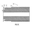
- FIG. 22is a side view of a coaxial cable having a hollow inner conductor as prepared by the cable preparation tool shown in FIG. 19 .
- FIG. 23is a greatly enlarged perspective view of the first projection of the cable preparation tool of FIGS. 14A-14B .
- the coaxial cable 30comprises an inner conductor 33 , an outer conductor 31 , and a dielectric 32 therebetween.
- the inner conductor 33is illustratively a hollow inner with an inner conductor dielectric core 36 .
- the outer conductor 31is illustratively a smooth outer conductor with a corrugated end 57 , but could be a corrugated outer conductor in other embodiments.
- the dielectrics 32 , 36may be foam dielectrics or other dielectric as known to those skilled in the art.
- the end of the coaxial cable 30is prepared so that the inner conductor 33 extends longitudinally outwardly beyond the end of the outer conductor 31 .
- portions of the dielectric 32are removed in a stair-stepped fashion so that the inner surface of the outer conductor 31 is also exposed.
- the coaxial cable 30illustratively includes an outer insulation jacket 34 stripped back a distance so that outer end portions of the outer conductor 31 are exposed.
- the outer conductor 31is flared outwardly to define a flared portion 55 .
- a corrugated portion 56 of the corrugated end 57 of outer conductor 31illustratively has a diameter less than that of other portions of the outer conductor.
- the coaxial cable 30may be prepared differently and may not have the corrugated portion 56 .
- Devices and methods for preparing the end of the coaxial cable 30will be described in detail below.
- the connector 10comprises a connector housing 12 defining a radially outer ramp 13 having a predetermined shape to receive the corrugated end 57 of the outer conductor 31 thereagainst.
- the radially outer ramp 13illustratively has a smooth continuous ramp surface, although it should be understood that other ramp surfaces may be used.
- the radially outer ramp 13may be a stair-stepped ramp or may be a radiused ramp.
- the connector 10includes an externally threaded back nut 14 threaded into the internally threaded rearward end of the connector housing 12 .
- the back nut 14illustratively comprises a polymer composite material, although of course in other applications the back nut could comprise a metal. Construction of the back nut 14 from the polymer composite material ensures that contact between the back nut and the outer conductor does not negatively affect intermodulation distortion (IMD). Furthermore, construction of the back nut 14 from a polymer composite material helps prevent galvanic corrosion between the components of the back nut and the coaxial cable 30 .
- a forward o-ring 28 and a rearward o-ring 25are illustratively provided to seal respective forward and rearward interfaces adjacent the back nut 14 and may prevent moisture ingress, as will be understood by those of skill in the art.
- the rearward o-ring 25has a retaining projection 60 extending outwardly therefrom. This retaining projection is received by recess 61 defined in the back nut 14 .
- the retaining projection 60 and recess 61securely locate the rearward o-ring 25 in the back nut and help prevent movement of the rearward o-ring during installation of the back nut 14 onto the coaxial cable 30 .
- a compressible ring 15compressibly clamps against the outer conductor 31 opposite the radially outer ramp 13 as the connector housing 12 and back nut 14 are engaged. This clamping helps to provide a secure mechanical and electrical connection between the outer conductor 31 and the radially outer ramp 13 . By maintaining a secure electrical connection, the intermodulation distortion of signals traveling through the coaxial cable 30 may be reduced.
- the compressible ring 15advantageously maintains a sufficient clamping force on the outer conductor 31 even if the outer conductor changes shape or size due to thermal expansion or creep, for example, whereas an arrangement of two wedging surfaces to clamp the outer conductor might lose clamping force and contact pressure if the outer conductor were to change shape or size. Furthermore, by maintaining a constant clamping force on the outer conductor 31 , the compressible ring 15 allows the connector 10 to be used with both smooth wall outer conductor coaxial cables 30 corrugated outer conductor coaxial cables. In addition the compressible ring 15 allows the connector 10 to be used on a variety of coaxial cables with different thicknesses, and on a variety of coaxial cables with outer conductors having different thicknesses.
- the compressible ring 15illustratively comprises an electrically conductive compressible coil spring having an axis coaxial with that of the connector housing 12 , although those of skill in the art will appreciate that any suitable compressible ring may be used. In some applications, the compressible ring 15 may not be electrically conductive. Indeed, the compressible ring 15 may be constructed from an electrically conductive material then coated with a non-conductive coating, such as a polymer coating. Alternatively, the compressible ring 15 may be constructed from a non-conductive material.
- the back nut 14illustratively includes a ferrule 35 ( FIGS. 6 , 9 ) to press against the compressible ring 15 as the connector housing 12 and back nut 14 are engaged.
- the ferrule 35is illustratively constructed from a polymer composite material, although of course the ferrule may also be constructed from metal and formed by casting or metal injection molding.
- the ferrulehas a retaining projection 62 extending radially outwardly therefrom to engage a retaining projection 63 of the back nut 14 .
- the retaining projections 62 , 63engage when the back nut 14 is advanced axially away from the connector housing 12 so that the ferrule 35 remains in the back nut.
- the ferrule 35is optional and may not be included in all applications.
- a center contact 17is supported in the connector housing 12 by an insulator member 18 ( FIG. 7 ) and is electrically connected to the inner conductor 33 .
- the insulator member 18comprises a radially outer support portion 21 to radially support the outer conductor 31 opposite the compressible ring 15 .
- This radial supportsupports the outer conductor 31 radially outwardly as the compressible ring 15 urges the outer conductor radially inwardly.
- the radially outer support portion 21helps to reduce the chance of a loss of electrical contact between the outer conductor 31 and the radially outer ramp 13 due to flexing of the coaxial cable 30 or due to compression of the dielectric 32 .
- the insulator member 18illustratively includes a rearward portion 19 engaging the dielectric 32 of the coaxial cable 30 .
- the illustrated insulator member 18is a monolithically formed unit. Of course, the insulator member 18 may instead comprise a two-piece unit.
- a portion of the connector housing 12 and a portion of the back nut 14include respective contacting portions defining a positive stop 29 when fully engaged. More particularly, a back end 27 of the connector housing 12 and a shoulder 27 of the back nut 14 define the positive stop 29 , although it should be understood that other variations of the positive stop are possible. Indeed, the connector housing 12 may have a shoulder to engage with a front portion of the back nut 14 to define the positive stop 29 .
- the positive stop 29helps prevent overtightening of the engagement between the connector housing 12 and the back nut 14 that may generate compression and or shearing forces at potentially damaging levels.
- the positive stop 29therefore facilitates easy installation of the connector 10 on the coaxial cable 30 by eliminating the need for a torque wrench or other torque limiting tool.
- the connector 10 ′may also be usable with coaxial cables 30 ′ having corrugated outer conductors 31 ′.
- Those other elements not specifically mentionedare indicated with prime notation and are similar to the elements described above with reference to FIG. 1 . Accordingly, those other elements require no further description herein.
- the rearward o-ring 25 ′′may lack a retaining projection. Instead, in such an embodiment, the rearward o-ring 25 ′′ is received by an o-ring pocket 62 ′′.
- the coaxial cable 30 ′′illustratively has a hollow inner conductor 33 ′′ without an inner conductor dielectric. Those other elements not specifically mentioned are indicated with double prime notation and are similar to the elements described above with reference to FIG. 1 . Accordingly, those other elements require no further description herein.
- the connector housing 12 and back nut 14may be used.
- the connector housing 12 ′′is threadingly received by the back nut 14 ′′′.
- the outer conductor 31 ′′′does not have a corrugated end and that the radially outer ramp 13 ′′′ is not shaped to receive such a corrugated end. Accordingly, skilled artisans will understand that such a feature is optional.
- there is no ferrule. Those other elements not specifically mentionedare indicated with triple prime notation and are similar to the elements described above with reference to FIG. 11 . Accordingly, those other elements require no further description herein.
- Another aspectis directed to a method of making a connector 10 to be attached to a coaxial cable 30 comprising an inner conductor 33 , an outer conductor 31 , and a dielectric therebetween 32 .
- the methodcomprises defining a radially outer ramp 13 on a connector housing 12 to receive the outer conductor thereagainst 31 and forming a compressible ring 15 to compressibly clamp against the outer conductor opposite the radially outer ramp as the connector housing and a back nut 14 are engaged.
- An insulator member 18is positioned in the connector housing 12 for carrying a center contact 17 to be coupled to the inner conductor 33 and comprising a radially outer support portion 21 to radially support the outer conductor 31 opposite the compressible ring 15 .
- a cable end preparation tool 40 for a coaxial cable 30is now described. It should be noted that, while the tool 40 is described herein by way of example for use with cellular tower cable installations, the tool may of course be used for cable end preparation in other applications as well.
- the coaxial cable 30comprises an inner conductor 33 , an outer conductor 31 , and a dielectric 32 therebetween.
- An optional dielectric jacket 51surrounds the outer conductor 31 . It should be appreciated that the end of the illustrated coaxial cable 30 has been prepared by the tool 40 .
- the cable end preparation tool 40may also be used with a coaxial cable having a corrugated outer conductor. Before using the cable end preparation tool 40 , a technician will typically cut the coaxial cable 30 . The coaxial cable 30 is cut so that the outer conductor 31 and dielectric 32 are flush with each other while the inner conductor 33 protrudes therebeyond.
- the cable end preparation tool 40illustratively comprises a body 41 having a central opening 42 therein.
- the central opening 42may be sized according to the coaxial cable 30 size and may receive the inner conductor 33 to steady and align the tool 40 on the cable end so that the user may push the body 41 toward the cable 51 and rotate or twist it about the central axis thereof.
- the body 41is disk shaped, but other body shapes may also be used in different applications.
- the body 41may be made from a variety of materials, such as metal and plastic, for example, using common manufacturing techniques known to those skilled in the art.
- the bodymay include a plurality of raised gripping surfaces 66 (knurls, for example) thereon to help facilitate gripping by the user, although a variety of textured surfaces or other gripping features (e.g. dimples, grooves, etc) may also be used, if desired, but such gripping features are in no way required.
- a blade 43is carried by the body and is for removing a portion of the dielectric 32 between the inner conductor and the outer conductor when the body 41 is rotated about the coaxial cable 30 .
- the removal of the portion of the dielectric 32occurs when the user rotates the body 41 by hand and pushes the body toward the cable 30 .
- the blade 43need not necessarily strip all of the dielectric 32 from the outer conductor 31 and the inner conductor 33 in all applications. That is, a residual amount of dielectric material may remain on the outer conductor 31 and the inner conductor 33 , which may be cleaned off by hand if desired. Skilled artisans will recognize that there may be an adhesive layer between the outer conductor 31 and the dielectric 32 and that a residual amount of this adhesive layer may remain after the blade 43 is used to strip the dielectric from the outer conductor.
- the body 42also illustratively includes a blade access opening 48 , which not only allows cuttings to pass through the cable end preparation tool 40 but may also allow the blade to be removed and/or replaced, if desired.
- the toolincludes a first projection 44 ( FIG. 23 ) carried by the body 41 and having a predetermined shape for flaring an end portion of the outer conductor 55 when the body is rotated relative to the coaxial cable 30 .
- the first projection 44has an outwardly extending portion 69 having a predetermined shape for beginning flaring of an end portion of the outer conductor 31 when the body 41 is rotated relative to the coaxial cable 30 .
- the first projection 44continues causing the outer conductor 31 to flare outwardly. The result of this flaring is perhaps best shown by the flared end 55 of the coaxial cable 30 in FIG. 20 .
- the first projection 44need not have the outwardly extending portion 69 in all applications.
- the predetermined shape of the first projection 44may also remove at least a portion of a residual adhesive layer from the outer conductor 31 as the body 41 is rotated relative to the coaxial cable 30 .
- the removal of this adhesive layermay enhance an electrical contact made between the outer conductor 31 and a connector.
- a stabilizing projection 60extends outwardly from the body 41 .
- the stabilizing projection 60receives the jacket 34 of the coaxial cable 30 thereagainst during use of the tool 40 .
- This stabilizing projection 60helps to stabilize the tool 40 as it is rotated about the coaxial cable 30 .
- the tool 40also includes a second projection 49 being movable with respect to the body 41 between an outer conductor engaging position (shown in FIG. 14A ) and a disengaged position (shown in FIG. 14B ).
- the second projection 49comprises a base 45 and a forming tip 46 carried thereby.
- the base 45is pivotally connected to the body 41 by a hinge pin 47 .
- the base 45 and the second projection 49can be integrally formed as a monolithic unit and the base may be coupled to the second projection by a tab.
- the forming tip 46corrugates the flared end portion 55 of the outer conductor 31 when the base 46 is in the outer conductor engaging position and the body 41 is rotated relative to the coaxial cable 30 .
- This corrugationresults in a corrugated portion 56 of the coaxial cable 30 having a diameter less than that of the outer conductor 31 .
- corrugatingmay not be required in certain implementations depending upon the given cable and connector type, and thus in such applications use of the second projection 49 may not be required.
- At least one of the blade 43 , first projection 44 , and second projection 49may be removably mounted to the body 41 . This may allow for the replacement of the blade 43 , first projection 44 , and second projection 49 if one thereof becomes damaged or worn. Further, this may allow for the blade 43 to be removed, sharpened, then reattached to the body 41 .
- the blade 43 , first projection 44 , and second projection 49are each on a same side of the body 41 .
- each of the blade 43 , first projection 44 , and second projection 49need not each be on a same side of the body 41 .
- FIGS. 15A and 15Billustrate an alternative embodiment of the cable end preparation tool 40 ′ where the first projection 44 ′ and second projection 49 ′ are each on carried by a first side 57 ′ of the body 41 ′.
- the blade 43 ′is carried by a second side 58 ′ of the body.
- Thismay advantageously allow the dielectric removal and flaring functions of the tool 40 ′ to be performed at separate times.
- a pair of hinge tabs 47 ′may extend radially inwardly from the second projection 49 ′. These hinge tabs 47 ′ are received by hinge tab receiver holes 63 ′ defined in the body 41 ′ of the tool 40 ′.
- the body 41 ′′, the blade 43 ′′, the first projection 44 ′′, and the second projection 49 ′′are integrally formed as a monolithic unit.
- a flexible strap 67 ′′connects the second projection 49 ′′ to the body 41 ′′.
- a stress relieving projection 62 ′′extends outwardly from the second projection 49 ′′. This stress relieving projection 62 ′′ is received by a groove 61 ′′ defined in the body 41 ′′ of the tool 40 ′′ and reduces stress on the flexible strap 67 ′′ when a technician is using the tool 40 ′′ to corrugate a coaxial cable.
- FIG. 18Shown in FIG. 18 is an embodiment of the tool 40 ′′′ where the body has a retaining groove 61 ′′′ defined therein.
- a retaining projection 62 ′′′extends outwardly from the second projection 49 ′′′.
- the hinge pin 47 ′′′extends through holes in the retaining groove 61 ′′′ and retaining projection 62 ′′′ to thereby secure the second projection 49 ′′′ to the body 41 ′′′ of the tool 40 ′′′.
- the body 41 ′′′′carries a central rotation guide 65 ′′′′.
- the central rotation guide 65 ′′′′is to be inserted into a hollow inner conductor 33 ′ ( FIG. 22 ). Once the central rotation guide 65 ′′′′ is inserted into the hollow inner conductor 33 ′, the tool 40 ′′′′ may be rotated about the coaxial cable 30 ′.
- the central rotation guide 65 ′′′′provides support to the inner conductor 33 ′ so that it is not bent or crushes during preparation of the coaxial cable 30 ′.
- a method of preparing a coaxial cable 30 with a cable end preparation tool 40 ′ for use with a connector 10is now described.
- a technicianwill typically cut the coaxial cable 30 .
- the coaxial cable 30may be cut flush, although preferably may be cut so that the outer conductor 31 and dielectric 32 are flush with each other while the inner conductor 33 protrudes therebeyond.
- the back nut 14 of the connector 10is then positioned on the coaxial cable 30 and slid away from the cable end.
- the inner conductor 33 of the coaxial cable 30is then inserted into the central opening 42 ′ of the tool 40 ′ so that the second side 58 ′ of the tool is facing the cable end.
- the body 41 ′ of the tool 40 ′is then rotated with respect to the cable 30 to thereby remove a portion of the dielectric 32 between the inner conductor 33 and the outer conductor 31 .
- the tool 40 ′is then removed from the inner conductor 33 of the cable 30 and replaced on the inner conductor with the first end 57 ′ of the body 41 ′ facing the cable end.
- the body 41 ′ of the tool 40 ′is then rotated with respect to the cable 30 to flare an end portion of the outer conductor (see flared end portion 55 of FIG. 6 ).
- the second projection 49 ′ of the tool 30 ′is set to the outer conductor engaging position and the body 41 ′ is rotated with respect to the cable to corrugate the flared end portion 55 of the outer conductor 31 (see corrugation 56 of FIG. 21 ).
- the connector housing 12is then inserted onto the cable end so that the flared portion 55 of the coaxial cable 30 is positioned adjacent the radially outer ramp 13 and the radially outer support portion 21 of the insulator member 18 is supporting the outer conductor 31 .
- the back nut back nut 14is then threaded into the connector housing 12 until the positive stop 29 therebetween is engaged. As the back nut 14 is threaded into the connector housing 12 , the compressible ring 15 compressibly clamps against the outer conductor 31 opposite the radially outer ramp 13 .
- the connector 10 and tool 40 ′ as described in this methodmay have any or all of the features described hereinbefore.
- a method aspectis directed to a method of preparing an end of a coaxial cable 30 comprising an inner conductor 31 , an outer conductor 33 , and a dielectric 32 therebetween, using a cable end preparation tool 40 .
- the methodcomprises positioning the cable end preparation tool 40 adjacent the coaxial cable 30 end and removing a portion of the dielectric 32 with a blade 43 carried by a body 41 of the cable end preparation tool by rotating the body relative to the coaxial cable.
- the methodincludes flaring an end portion of the outer conductor 31 with a first projection 44 carried by the body 41 by rotating the body relative to the coaxial cable 30 .
- the methodincludes corrugating the flared end portion of the outer conductor 31 with a second projection 49 carried by the body 41 and being movable with respect to the body between an outer conductor engaging position and a disengaged position by rotating the body relative to the coaxial cable 30 when the second projection is in the outer conductor engaging position.
- connectors 10 for coaxial cables 30may be found in co-pending applications CONNECTOR WITH POSITIVE STOP FOR COAXIAL CABLE AND ASSOCIATED METHODS, CONNECTOR INCLUDING COMPRESSIBLE RING FOR COAXIAL CABLE AND ASSOCIATED METHODS, CONNECTOR WITH POSITIVE STOP AND COMPRESSIBLE RING FOR COAXIAL CABLE AND ASSOCIATED METHODS, and CONNECTOR WITH RETAINING RING FOR COAXIAL CABLE AND ASSOCIATED METHODS, the entire disclosures of which are hereby incorporated by reference.
Landscapes
- Engineering & Computer Science (AREA)
- Manufacturing & Machinery (AREA)
- Coupling Device And Connection With Printed Circuit (AREA)
Abstract
Description
Claims (13)
Priority Applications (2)
| Application Number | Priority Date | Filing Date | Title |
|---|---|---|---|
| US12/277,152US8136234B2 (en) | 2008-11-24 | 2008-11-24 | Flaring coaxial cable end preparation tool and associated methods |
| CN200910258482XACN101950909B (en) | 2008-11-24 | 2009-11-24 | Flaring coaxial cable end preparation tool and associated methods |
Applications Claiming Priority (1)
| Application Number | Priority Date | Filing Date | Title |
|---|---|---|---|
| US12/277,152US8136234B2 (en) | 2008-11-24 | 2008-11-24 | Flaring coaxial cable end preparation tool and associated methods |
Publications (2)
| Publication Number | Publication Date |
|---|---|
| US20100126011A1 US20100126011A1 (en) | 2010-05-27 |
| US8136234B2true US8136234B2 (en) | 2012-03-20 |
Family
ID=42194890
Family Applications (1)
| Application Number | Title | Priority Date | Filing Date |
|---|---|---|---|
| US12/277,152Expired - Fee RelatedUS8136234B2 (en) | 2008-11-24 | 2008-11-24 | Flaring coaxial cable end preparation tool and associated methods |
Country Status (2)
| Country | Link |
|---|---|
| US (1) | US8136234B2 (en) |
| CN (1) | CN101950909B (en) |
Cited By (5)
| Publication number | Priority date | Publication date | Assignee | Title |
|---|---|---|---|---|
| US20130203287A1 (en)* | 2012-02-06 | 2013-08-08 | John Mezzalingua Associates, Inc. | Port assembly connector for engaging a coaxial cable and an outer conductor |
| US8556655B2 (en)* | 2010-11-22 | 2013-10-15 | Andrew Llc | Friction weld coaxial connector |
| US20150144398A1 (en)* | 2013-11-26 | 2015-05-28 | Andrew Llc | Adapter for sealing cover for electrical interconnections |
| US20170317434A1 (en)* | 2014-09-11 | 2017-11-02 | Commscope Technologies Llc | Coaxial cable and connector assembly |
| US11217948B2 (en)* | 2015-06-10 | 2022-01-04 | Ppc Broadband, Inc. | Connector for engaging an outer conductor of a coaxial cable |
Families Citing this family (4)
| Publication number | Priority date | Publication date | Assignee | Title |
|---|---|---|---|---|
| US7931499B2 (en) | 2009-01-28 | 2011-04-26 | Andrew Llc | Connector including flexible fingers and associated methods |
| US8206176B2 (en)* | 2010-02-16 | 2012-06-26 | Andrew Llc | Connector for coaxial cable having rotational joint between insulator member and connector housing and associated methods |
| DE102011106736B4 (en)* | 2011-06-28 | 2013-01-31 | Ims Connector Systems Gmbh | Housing plug and housing socket and tools for it |
| CH706510A2 (en)* | 2012-05-15 | 2013-11-15 | Huber+Suhner Ag | Method and device for producing an operative connection between a connector and a cable. |
Citations (99)
| Publication number | Priority date | Publication date | Assignee | Title |
|---|---|---|---|---|
| US3040288A (en) | 1958-02-27 | 1962-06-19 | Phelps Dodge Copper Prod | Means for connecting metal jacketed coaxial cable |
| US3103548A (en) | 1961-11-16 | 1963-09-10 | Crimped coaxial cable termination | |
| US3106599A (en) | 1961-11-10 | 1963-10-08 | Technical Appliance Corp | Expansible connector for rigid coaxial transmission line |
| US3671926A (en) | 1970-08-03 | 1972-06-20 | Lindsay Specialty Prod Ltd | Coaxial cable connector |
| US3744011A (en) | 1971-10-28 | 1973-07-03 | Itt | Coaxial cable connector |
| US3757279A (en) | 1972-05-15 | 1973-09-04 | Jerrold Electronics Corp | Tor diameters electrical connector operable for diverse coaxial cable center conduc |
| US3761870A (en) | 1972-07-26 | 1973-09-25 | Tidal Sales Corp | Co-axial connector including positive clamping features for providing reliable electrical connections to the center and outer conductors of a co-axial cable |
| US3847463A (en) | 1973-04-11 | 1974-11-12 | Gilbert Engineering Co | Cable connector apparatus |
| US3915539A (en) | 1971-05-20 | 1975-10-28 | C S Antennas Ltd | Coaxial connectors |
| US4046451A (en) | 1976-07-08 | 1977-09-06 | Andrew Corporation | Connector for coaxial cable with annularly corrugated outer conductor |
| US4491685A (en) | 1983-05-26 | 1985-01-01 | Armex Cable Corporation | Cable connector |
| US4557546A (en) | 1983-08-18 | 1985-12-10 | Sealectro Corporation | Solderless coaxial connector |
| US4585289A (en) | 1983-05-04 | 1986-04-29 | Societe Anonyme Dite: Les Cables De Lyon | Coaxial cable core extension |
| US4676577A (en) | 1985-03-27 | 1987-06-30 | John Mezzalingua Associates, Inc. | Connector for coaxial cable |
| US4915651A (en) | 1987-10-26 | 1990-04-10 | At&T Philips Telecommunications B. V. | Coaxial connector |
| US4923412A (en) | 1987-11-30 | 1990-05-08 | Pyramid Industries, Inc. | Terminal end for coaxial cable |
| US4979299A (en)* | 1989-05-10 | 1990-12-25 | Zdzislaw Bieganski | Coaxial cable stripper |
| US5009130A (en)* | 1988-12-22 | 1991-04-23 | Zdzislaw Bieganski | Coaxial cable stripper |
| US5105542A (en)* | 1989-12-06 | 1992-04-21 | Nakajima Tsushinki Kogyo Co., Ltd. | Tool for removing coverings of a coaxial cable |
| US5137470A (en) | 1991-06-04 | 1992-08-11 | Andrew Corporation | Connector for coaxial cable having a helically corrugated inner conductor |
| US5154636A (en) | 1991-01-15 | 1992-10-13 | Andrew Corporation | Self-flaring connector for coaxial cable having a helically corrugated outer conductor |
| US5267877A (en) | 1992-11-23 | 1993-12-07 | Dynawave Incorporated | Coaxial connector for corrugated conduit |
| US5281167A (en) | 1993-05-28 | 1994-01-25 | The Whitaker Corporation | Coaxial connector for soldering to semirigid cable |
| US5352134A (en) | 1993-06-21 | 1994-10-04 | Cabel-Con, Inc. | RF shielded coaxial cable connector |
| US5352127A (en) | 1993-02-24 | 1994-10-04 | John Muller | Cable connector and method |
| US5509821A (en) | 1994-11-14 | 1996-04-23 | Itt Corporation | D-sub connector |
| US5511305A (en)* | 1994-06-06 | 1996-04-30 | Commscope | Core finish tool for coaxial cable and associated method |
| US5545059A (en) | 1995-03-30 | 1996-08-13 | Radio Frequency Systems, Inc. | Connector for a hollow center conductor of a radio frequency cable |
| US5576675A (en) | 1995-07-05 | 1996-11-19 | Wiltron Company | Microwave connector with an inner conductor that provides an axially resilient coaxial connection |
| US5722856A (en) | 1995-05-02 | 1998-03-03 | Huber+Suhner Ag | Apparatus for electrical connection of a coaxial cable and a connector |
| US5785554A (en) | 1996-03-28 | 1998-07-28 | Ohshiro; Yoshio | Coaxial connector |
| US5795188A (en) | 1996-03-28 | 1998-08-18 | Andrew Corporation | Connector kit for a coaxial cable, method of attachment and the resulting assembly |
| US5830009A (en) | 1995-09-12 | 1998-11-03 | Rosenberger Hochfrequenztechnik Gmbh & Co. | Device for connecting a coaxial plug to a coaxial cable |
| US5938474A (en) | 1997-12-10 | 1999-08-17 | Radio Frequency Systems, Inc. | Connector assembly for a coaxial cable |
| US5992010A (en)* | 1997-11-03 | 1999-11-30 | Zamanzadeh; Manouchehr | Coaxial cable connector tool |
| US6019636A (en) | 1998-10-20 | 2000-02-01 | Eagle Comtronics, Inc. | Coaxial cable connector |
| US6109964A (en) | 1998-04-06 | 2000-08-29 | Andrew Corporation | One piece connector for a coaxial cable with an annularly corrugated outer conductor |
| US6131289A (en)* | 1999-03-24 | 2000-10-17 | Capewell Components Company, Llc | Cable slitter |
| US6133532A (en) | 1998-02-17 | 2000-10-17 | Teracom Components Ab | Contact device |
| US6148513A (en) | 1996-12-21 | 2000-11-21 | Alcatel | Method of applying a connecting element to a high-frequency cable in a moisture-proof manner |
| US6203368B1 (en) | 1997-12-19 | 2001-03-20 | The Whitaker Corporation | Electrical connector with seizure screw |
| US6267621B1 (en) | 1998-10-08 | 2001-07-31 | Spinner Gmbh Elektrotechnische Fabrik | Connector for a coaxial cable with annularly corrugated outer cable conductor |
| US6309250B1 (en) | 2000-08-10 | 2001-10-30 | Itt Manufacturing Enterprises, Inc. | Coaxial connector termination |
| US6332808B1 (en) | 1999-09-22 | 2001-12-25 | Mitsubishi Cable Industries, Ltd. | Connector structure |
| US6386915B1 (en) | 2000-11-14 | 2002-05-14 | Radio Frequency Systems, Inc. | One step connector |
| US6396367B1 (en) | 1999-04-22 | 2002-05-28 | Rosenberger Hochfrequenztechnik Gmbh & Co. | Coaxial connector |
| US6427331B1 (en)* | 2000-11-28 | 2002-08-06 | Capewell Components Company, Llc | Slitting and shaving tool for messengered cable |
| US6439924B1 (en) | 2001-10-11 | 2002-08-27 | Corning Gilbert Inc. | Solder-on connector for coaxial cable |
| US6462637B1 (en) | 1995-04-12 | 2002-10-08 | Itt Manufacturing Enterprises, Inc. | Electrical connector |
| US6607398B2 (en) | 2000-04-17 | 2003-08-19 | Corning Gilbert Incorporated | Connector for a coaxial cable with corrugated outer conductor |
| US6637101B2 (en)* | 2001-06-22 | 2003-10-28 | Radio Frequency Systems, Inc. | Coaxial cable preparation tool |
| US6668459B2 (en) | 2001-04-23 | 2003-12-30 | Corning Gilbert Inc. | Stripping tool for coaxial cable |
| US6692300B2 (en) | 1999-12-16 | 2004-02-17 | Mitsubishi Cable Industries, Ltd. | Coaxial cable connector |
| US6793529B1 (en) | 2003-09-30 | 2004-09-21 | Andrew Corporation | Coaxial connector with positive stop clamping nut attachment |
| US6802739B2 (en) | 2003-01-16 | 2004-10-12 | Corning Gilbert Inc. | Coaxial cable connector |
| US6808415B1 (en) | 2004-01-26 | 2004-10-26 | John Mezzalingua Associates, Inc. | Clamping and sealing mechanism with multiple rings for cable connector |
| US6824415B2 (en) | 2001-11-01 | 2004-11-30 | Andrew Corporation | Coaxial connector with spring loaded coupling mechanism |
| US6835095B2 (en) | 2003-05-16 | 2004-12-28 | Parry Chen | Radio frequency coaxial connector |
| US6848939B2 (en) | 2003-06-24 | 2005-02-01 | Stirling Connectors, Inc. | Coaxial cable connector with integral grip bushing for cables of varying thickness |
| US6848941B2 (en) | 2003-02-13 | 2005-02-01 | Andrew Corporation | Low cost, high performance cable-connector system and assembly method |
| US6848931B2 (en) | 2002-07-19 | 2005-02-01 | Andrew Corporation | Quick attachment SMA connector |
| US6863565B1 (en) | 2004-07-13 | 2005-03-08 | Palco Connector Incorporated | Constant impedance bullet connector for a semi-rigid coaxial cable |
| US6893290B2 (en) | 2002-09-12 | 2005-05-17 | Andrew Corporation | Coaxial cable connector and tool and method for connecting a coaxial cable |
| US20050118865A1 (en) | 2003-12-01 | 2005-06-02 | Corning Gilbert Inc. | Coaxial connector and method |
| US6926555B2 (en) | 2003-10-09 | 2005-08-09 | Radio Frequency Systems, Inc. | Tuned radio frequency coaxial connector |
| US6939169B2 (en) | 2003-07-28 | 2005-09-06 | Andrew Corporation | Axial compression electrical connector |
| US7008264B2 (en) | 2004-01-29 | 2006-03-07 | Spinner Gmbh | Connector for coaxial cable with annularly corrugated outside conductor |
| US7011546B2 (en) | 2003-09-09 | 2006-03-14 | Commscope Properties, Llc | Coaxial connector with enhanced insulator member and associated methods |
| US20060112549A1 (en) | 2004-12-01 | 2006-06-01 | Henningsen Jimmy C | Method for standardizing coaxial cable jacket diameters and related preparation tool |
| US7059162B1 (en) | 2004-08-05 | 2006-06-13 | Capewell Components, Llc | Dual flaring tool |
| US7077700B2 (en) | 2004-12-20 | 2006-07-18 | Corning Gilbert Inc. | Coaxial connector with back nut clamping ring |
| US7104839B2 (en) | 2004-06-15 | 2006-09-12 | Corning Gilbert Inc. | Coaxial connector with center conductor seizure |
| US7121883B1 (en) | 2005-06-06 | 2006-10-17 | John Mezzalingua Associates, Inc. | Coax connector having steering insulator |
| US7144272B1 (en) | 2005-11-14 | 2006-12-05 | Corning Gilbert Inc. | Coaxial cable connector with threaded outer body |
| US7156696B1 (en) | 2006-07-19 | 2007-01-02 | John Mezzalingua Associates, Inc. | Connector for corrugated coaxial cable and method |
| US7163420B2 (en) | 2004-02-04 | 2007-01-16 | John Mezzalingua Assoicates, Inc. | Compression connector with integral coupler |
| US7171753B2 (en)* | 2004-06-15 | 2007-02-06 | Andrew Corporation | Multi-cable jacket removal tool |
| US7179121B1 (en) | 2005-09-23 | 2007-02-20 | Corning Gilbert Inc. | Coaxial cable connector |
| US20070149047A1 (en) | 2005-12-22 | 2007-06-28 | Spinner Gmbh | Coaxial Plug-Type Connector and Method for Mounting the Same |
| US7329149B2 (en) | 2004-01-26 | 2008-02-12 | John Mezzalingua Associates, Inc. | Clamping and sealing mechanism with multiple rings for cable connector |
| US7335059B2 (en) | 2006-03-08 | 2008-02-26 | Commscope, Inc. Of North Carolina | Coaxial connector including clamping ramps and associated method |
| US7381089B2 (en) | 2004-08-31 | 2008-06-03 | Itt Manufacturing Enterprises, Inc. | Coaxial cable-connector termination |
| US7422477B2 (en) | 2006-12-04 | 2008-09-09 | John Mezzalingva Assoc., Inc. | Insulator for coaxial cable connectors |
| US7435135B2 (en) | 2007-02-08 | 2008-10-14 | Andrew Corporation | Annular corrugated coaxial cable connector with polymeric spring finger nut |
| US7448906B1 (en) | 2007-08-22 | 2008-11-11 | Andrew Llc | Hollow inner conductor contact for coaxial cable connector |
| US20090053931A1 (en)* | 2007-08-22 | 2009-02-26 | Andrew Llc | Sealed Inner Conductor Contact for Coaxial Cable Connector |
| US20090186521A1 (en) | 2008-01-22 | 2009-07-23 | Andrew Llc | Locking threaded connection coaxial connector |
| US7621778B1 (en) | 2008-07-28 | 2009-11-24 | Commscope, Inc. Of North Carolina | Coaxial connector inner contact arrangement |
| US7632143B1 (en) | 2008-11-24 | 2009-12-15 | Andrew Llc | Connector with positive stop and compressible ring for coaxial cable and associated methods |
| US7635283B1 (en) | 2008-11-24 | 2009-12-22 | Andrew Llc | Connector with retaining ring for coaxial cable and associated methods |
| US7694420B2 (en)* | 2007-07-19 | 2010-04-13 | John Mezzalingua Associates, Inc. | Coaxial cable preparation tool and method of use thereof |
| US7727013B1 (en) | 2009-01-29 | 2010-06-01 | Andrew Llc | Low PIM rotatable connector |
| US7731529B1 (en) | 2008-11-24 | 2010-06-08 | Andrew Llc | Connector including compressible ring for clamping a conductor of a coaxial cable and associated methods |
| US7785144B1 (en) | 2008-11-24 | 2010-08-31 | Andrew Llc | Connector with positive stop for coaxial cable and associated methods |
| US7798847B2 (en) | 2008-10-07 | 2010-09-21 | Andrew Llc | Inner conductor sealing insulator for coaxial connector |
| US7798848B2 (en) | 2009-01-29 | 2010-09-21 | Andrew Llc | Inner contact supporting and biasing insulator |
| US7806724B2 (en) | 2008-11-05 | 2010-10-05 | Andrew Llc | Coaxial connector for cable with a solid outer conductor |
| US7824215B2 (en) | 2008-11-05 | 2010-11-02 | Andrew Llc | Axial compression coaxial connector with grip surfaces |
| US7824214B2 (en) | 2008-06-30 | 2010-11-02 | Commscope, Inc. Of North Carolina | Coupling nut with cable jacket retention |
Family Cites Families (1)
| Publication number | Priority date | Publication date | Assignee | Title |
|---|---|---|---|---|
| US7001546B2 (en)* | 2001-08-09 | 2006-02-21 | G H. Tool & Mold, Inc. | Method for thermostatically controlling mold temperatures |
- 2008
- 2008-11-24USUS12/277,152patent/US8136234B2/ennot_activeExpired - Fee Related
- 2009
- 2009-11-24CNCN200910258482XApatent/CN101950909B/ennot_activeExpired - Fee Related
Patent Citations (100)
| Publication number | Priority date | Publication date | Assignee | Title |
|---|---|---|---|---|
| US3040288A (en) | 1958-02-27 | 1962-06-19 | Phelps Dodge Copper Prod | Means for connecting metal jacketed coaxial cable |
| US3106599A (en) | 1961-11-10 | 1963-10-08 | Technical Appliance Corp | Expansible connector for rigid coaxial transmission line |
| US3103548A (en) | 1961-11-16 | 1963-09-10 | Crimped coaxial cable termination | |
| US3671926A (en) | 1970-08-03 | 1972-06-20 | Lindsay Specialty Prod Ltd | Coaxial cable connector |
| US3915539A (en) | 1971-05-20 | 1975-10-28 | C S Antennas Ltd | Coaxial connectors |
| US3744011A (en) | 1971-10-28 | 1973-07-03 | Itt | Coaxial cable connector |
| US3757279A (en) | 1972-05-15 | 1973-09-04 | Jerrold Electronics Corp | Tor diameters electrical connector operable for diverse coaxial cable center conduc |
| US3761870A (en) | 1972-07-26 | 1973-09-25 | Tidal Sales Corp | Co-axial connector including positive clamping features for providing reliable electrical connections to the center and outer conductors of a co-axial cable |
| US3847463A (en) | 1973-04-11 | 1974-11-12 | Gilbert Engineering Co | Cable connector apparatus |
| US4046451A (en) | 1976-07-08 | 1977-09-06 | Andrew Corporation | Connector for coaxial cable with annularly corrugated outer conductor |
| US4585289A (en) | 1983-05-04 | 1986-04-29 | Societe Anonyme Dite: Les Cables De Lyon | Coaxial cable core extension |
| US4491685A (en) | 1983-05-26 | 1985-01-01 | Armex Cable Corporation | Cable connector |
| US4557546A (en) | 1983-08-18 | 1985-12-10 | Sealectro Corporation | Solderless coaxial connector |
| US4676577A (en) | 1985-03-27 | 1987-06-30 | John Mezzalingua Associates, Inc. | Connector for coaxial cable |
| US4915651A (en) | 1987-10-26 | 1990-04-10 | At&T Philips Telecommunications B. V. | Coaxial connector |
| US4923412A (en) | 1987-11-30 | 1990-05-08 | Pyramid Industries, Inc. | Terminal end for coaxial cable |
| US5009130A (en)* | 1988-12-22 | 1991-04-23 | Zdzislaw Bieganski | Coaxial cable stripper |
| US4979299A (en)* | 1989-05-10 | 1990-12-25 | Zdzislaw Bieganski | Coaxial cable stripper |
| US5105542A (en)* | 1989-12-06 | 1992-04-21 | Nakajima Tsushinki Kogyo Co., Ltd. | Tool for removing coverings of a coaxial cable |
| US5154636A (en) | 1991-01-15 | 1992-10-13 | Andrew Corporation | Self-flaring connector for coaxial cable having a helically corrugated outer conductor |
| US5137470A (en) | 1991-06-04 | 1992-08-11 | Andrew Corporation | Connector for coaxial cable having a helically corrugated inner conductor |
| US5267877A (en) | 1992-11-23 | 1993-12-07 | Dynawave Incorporated | Coaxial connector for corrugated conduit |
| US5352127A (en) | 1993-02-24 | 1994-10-04 | John Muller | Cable connector and method |
| US5281167A (en) | 1993-05-28 | 1994-01-25 | The Whitaker Corporation | Coaxial connector for soldering to semirigid cable |
| US5352134A (en) | 1993-06-21 | 1994-10-04 | Cabel-Con, Inc. | RF shielded coaxial cable connector |
| US5511305A (en)* | 1994-06-06 | 1996-04-30 | Commscope | Core finish tool for coaxial cable and associated method |
| US5509821A (en) | 1994-11-14 | 1996-04-23 | Itt Corporation | D-sub connector |
| US5545059A (en) | 1995-03-30 | 1996-08-13 | Radio Frequency Systems, Inc. | Connector for a hollow center conductor of a radio frequency cable |
| US6462637B1 (en) | 1995-04-12 | 2002-10-08 | Itt Manufacturing Enterprises, Inc. | Electrical connector |
| US5722856A (en) | 1995-05-02 | 1998-03-03 | Huber+Suhner Ag | Apparatus for electrical connection of a coaxial cable and a connector |
| US5576675A (en) | 1995-07-05 | 1996-11-19 | Wiltron Company | Microwave connector with an inner conductor that provides an axially resilient coaxial connection |
| US5830009A (en) | 1995-09-12 | 1998-11-03 | Rosenberger Hochfrequenztechnik Gmbh & Co. | Device for connecting a coaxial plug to a coaxial cable |
| US5785554A (en) | 1996-03-28 | 1998-07-28 | Ohshiro; Yoshio | Coaxial connector |
| US5795188A (en) | 1996-03-28 | 1998-08-18 | Andrew Corporation | Connector kit for a coaxial cable, method of attachment and the resulting assembly |
| US6148513A (en) | 1996-12-21 | 2000-11-21 | Alcatel | Method of applying a connecting element to a high-frequency cable in a moisture-proof manner |
| US5992010A (en)* | 1997-11-03 | 1999-11-30 | Zamanzadeh; Manouchehr | Coaxial cable connector tool |
| US5938474A (en) | 1997-12-10 | 1999-08-17 | Radio Frequency Systems, Inc. | Connector assembly for a coaxial cable |
| US6203368B1 (en) | 1997-12-19 | 2001-03-20 | The Whitaker Corporation | Electrical connector with seizure screw |
| US6133532A (en) | 1998-02-17 | 2000-10-17 | Teracom Components Ab | Contact device |
| US6109964A (en) | 1998-04-06 | 2000-08-29 | Andrew Corporation | One piece connector for a coaxial cable with an annularly corrugated outer conductor |
| US6267621B1 (en) | 1998-10-08 | 2001-07-31 | Spinner Gmbh Elektrotechnische Fabrik | Connector for a coaxial cable with annularly corrugated outer cable conductor |
| US6019636A (en) | 1998-10-20 | 2000-02-01 | Eagle Comtronics, Inc. | Coaxial cable connector |
| US6131289A (en)* | 1999-03-24 | 2000-10-17 | Capewell Components Company, Llc | Cable slitter |
| US6396367B1 (en) | 1999-04-22 | 2002-05-28 | Rosenberger Hochfrequenztechnik Gmbh & Co. | Coaxial connector |
| US6332808B1 (en) | 1999-09-22 | 2001-12-25 | Mitsubishi Cable Industries, Ltd. | Connector structure |
| US6692300B2 (en) | 1999-12-16 | 2004-02-17 | Mitsubishi Cable Industries, Ltd. | Coaxial cable connector |
| US6607398B2 (en) | 2000-04-17 | 2003-08-19 | Corning Gilbert Incorporated | Connector for a coaxial cable with corrugated outer conductor |
| US6309250B1 (en) | 2000-08-10 | 2001-10-30 | Itt Manufacturing Enterprises, Inc. | Coaxial connector termination |
| US6386915B1 (en) | 2000-11-14 | 2002-05-14 | Radio Frequency Systems, Inc. | One step connector |
| US6427331B1 (en)* | 2000-11-28 | 2002-08-06 | Capewell Components Company, Llc | Slitting and shaving tool for messengered cable |
| US6668459B2 (en) | 2001-04-23 | 2003-12-30 | Corning Gilbert Inc. | Stripping tool for coaxial cable |
| US6637101B2 (en)* | 2001-06-22 | 2003-10-28 | Radio Frequency Systems, Inc. | Coaxial cable preparation tool |
| US6439924B1 (en) | 2001-10-11 | 2002-08-27 | Corning Gilbert Inc. | Solder-on connector for coaxial cable |
| US6824415B2 (en) | 2001-11-01 | 2004-11-30 | Andrew Corporation | Coaxial connector with spring loaded coupling mechanism |
| US6848931B2 (en) | 2002-07-19 | 2005-02-01 | Andrew Corporation | Quick attachment SMA connector |
| US6893290B2 (en) | 2002-09-12 | 2005-05-17 | Andrew Corporation | Coaxial cable connector and tool and method for connecting a coaxial cable |
| US7134189B2 (en) | 2002-09-12 | 2006-11-14 | Andrew Corporation | Coaxial cable connector and tool and method for connecting a coaxial cable |
| US6802739B2 (en) | 2003-01-16 | 2004-10-12 | Corning Gilbert Inc. | Coaxial cable connector |
| US6848941B2 (en) | 2003-02-13 | 2005-02-01 | Andrew Corporation | Low cost, high performance cable-connector system and assembly method |
| US6835095B2 (en) | 2003-05-16 | 2004-12-28 | Parry Chen | Radio frequency coaxial connector |
| US6848939B2 (en) | 2003-06-24 | 2005-02-01 | Stirling Connectors, Inc. | Coaxial cable connector with integral grip bushing for cables of varying thickness |
| US6939169B2 (en) | 2003-07-28 | 2005-09-06 | Andrew Corporation | Axial compression electrical connector |
| US7011546B2 (en) | 2003-09-09 | 2006-03-14 | Commscope Properties, Llc | Coaxial connector with enhanced insulator member and associated methods |
| US6793529B1 (en) | 2003-09-30 | 2004-09-21 | Andrew Corporation | Coaxial connector with positive stop clamping nut attachment |
| US6926555B2 (en) | 2003-10-09 | 2005-08-09 | Radio Frequency Systems, Inc. | Tuned radio frequency coaxial connector |
| US20050118865A1 (en) | 2003-12-01 | 2005-06-02 | Corning Gilbert Inc. | Coaxial connector and method |
| US6808415B1 (en) | 2004-01-26 | 2004-10-26 | John Mezzalingua Associates, Inc. | Clamping and sealing mechanism with multiple rings for cable connector |
| US7329149B2 (en) | 2004-01-26 | 2008-02-12 | John Mezzalingua Associates, Inc. | Clamping and sealing mechanism with multiple rings for cable connector |
| US7008264B2 (en) | 2004-01-29 | 2006-03-07 | Spinner Gmbh | Connector for coaxial cable with annularly corrugated outside conductor |
| US7163420B2 (en) | 2004-02-04 | 2007-01-16 | John Mezzalingua Assoicates, Inc. | Compression connector with integral coupler |
| US7171753B2 (en)* | 2004-06-15 | 2007-02-06 | Andrew Corporation | Multi-cable jacket removal tool |
| US7104839B2 (en) | 2004-06-15 | 2006-09-12 | Corning Gilbert Inc. | Coaxial connector with center conductor seizure |
| US6863565B1 (en) | 2004-07-13 | 2005-03-08 | Palco Connector Incorporated | Constant impedance bullet connector for a semi-rigid coaxial cable |
| US7059162B1 (en) | 2004-08-05 | 2006-06-13 | Capewell Components, Llc | Dual flaring tool |
| US7381089B2 (en) | 2004-08-31 | 2008-06-03 | Itt Manufacturing Enterprises, Inc. | Coaxial cable-connector termination |
| US20060112549A1 (en) | 2004-12-01 | 2006-06-01 | Henningsen Jimmy C | Method for standardizing coaxial cable jacket diameters and related preparation tool |
| US7077700B2 (en) | 2004-12-20 | 2006-07-18 | Corning Gilbert Inc. | Coaxial connector with back nut clamping ring |
| US7121883B1 (en) | 2005-06-06 | 2006-10-17 | John Mezzalingua Associates, Inc. | Coax connector having steering insulator |
| US7179121B1 (en) | 2005-09-23 | 2007-02-20 | Corning Gilbert Inc. | Coaxial cable connector |
| US7144272B1 (en) | 2005-11-14 | 2006-12-05 | Corning Gilbert Inc. | Coaxial cable connector with threaded outer body |
| US20070149047A1 (en) | 2005-12-22 | 2007-06-28 | Spinner Gmbh | Coaxial Plug-Type Connector and Method for Mounting the Same |
| US7335059B2 (en) | 2006-03-08 | 2008-02-26 | Commscope, Inc. Of North Carolina | Coaxial connector including clamping ramps and associated method |
| US7156696B1 (en) | 2006-07-19 | 2007-01-02 | John Mezzalingua Associates, Inc. | Connector for corrugated coaxial cable and method |
| US7422477B2 (en) | 2006-12-04 | 2008-09-09 | John Mezzalingva Assoc., Inc. | Insulator for coaxial cable connectors |
| US7435135B2 (en) | 2007-02-08 | 2008-10-14 | Andrew Corporation | Annular corrugated coaxial cable connector with polymeric spring finger nut |
| US7694420B2 (en)* | 2007-07-19 | 2010-04-13 | John Mezzalingua Associates, Inc. | Coaxial cable preparation tool and method of use thereof |
| US7448906B1 (en) | 2007-08-22 | 2008-11-11 | Andrew Llc | Hollow inner conductor contact for coaxial cable connector |
| US20090053931A1 (en)* | 2007-08-22 | 2009-02-26 | Andrew Llc | Sealed Inner Conductor Contact for Coaxial Cable Connector |
| US20090186521A1 (en) | 2008-01-22 | 2009-07-23 | Andrew Llc | Locking threaded connection coaxial connector |
| US7824214B2 (en) | 2008-06-30 | 2010-11-02 | Commscope, Inc. Of North Carolina | Coupling nut with cable jacket retention |
| US7621778B1 (en) | 2008-07-28 | 2009-11-24 | Commscope, Inc. Of North Carolina | Coaxial connector inner contact arrangement |
| US7798847B2 (en) | 2008-10-07 | 2010-09-21 | Andrew Llc | Inner conductor sealing insulator for coaxial connector |
| US7806724B2 (en) | 2008-11-05 | 2010-10-05 | Andrew Llc | Coaxial connector for cable with a solid outer conductor |
| US7824215B2 (en) | 2008-11-05 | 2010-11-02 | Andrew Llc | Axial compression coaxial connector with grip surfaces |
| US7632143B1 (en) | 2008-11-24 | 2009-12-15 | Andrew Llc | Connector with positive stop and compressible ring for coaxial cable and associated methods |
| US7635283B1 (en) | 2008-11-24 | 2009-12-22 | Andrew Llc | Connector with retaining ring for coaxial cable and associated methods |
| US7731529B1 (en) | 2008-11-24 | 2010-06-08 | Andrew Llc | Connector including compressible ring for clamping a conductor of a coaxial cable and associated methods |
| US7785144B1 (en) | 2008-11-24 | 2010-08-31 | Andrew Llc | Connector with positive stop for coaxial cable and associated methods |
| US7727013B1 (en) | 2009-01-29 | 2010-06-01 | Andrew Llc | Low PIM rotatable connector |
| US7798848B2 (en) | 2009-01-29 | 2010-09-21 | Andrew Llc | Inner contact supporting and biasing insulator |
Non-Patent Citations (17)
| Title |
|---|
| Islam, "Axial Compression Connector," Nov. 3, 2008, pp. 1-25. |
| Islam, "Connector Including Compressible Ring for Coaxial Cable and Associated Methods," Nov. 24, 2008, pp. 1-30. |
| Islam, "Connector Including Flexible Fingers and Associated Methods," Jan. 28, 2009, pp. 1-26. |
| Islam, "Connector With Positive Stop and Compressible Ring for Coaxial Cable and Associated Methods," Nov. 24, 2008, pp. 1-25. |
| Islam, "Connector With Positive Stop for Coaxial Cable and Associated Methods," Nov. 24, 2008, pp. 1-22. |
| Islam, "Connector With Retaining Ring for Coaxial Cable and Associated Methods," Nov. 24, 2008, pp. 1-28. |
| Islam, "Inner Conductor Sealing Insulator for Coaxial Connector," Oct. 7, 2008, pp. 1-17. |
| Islam, "Inner Contact Supporting and Biasing Insulator," Jan. 29, 2009, pp. 1-16. |
| Paynter, "Coaxial Connector Inner Contact Arrangement," Jul. 15, 2008, pp. 1-17. |
| Paynter, "Coupling Nut With Cable Jacket Retention," Jun. 29, 2008, pp. 1-20. |
| Paynter, "Insertion Coupling Coaxial Connector," Nov. 3, 2008, pp. 1-24. |
| Paynter, "Low PIM Rotatable Connector," Jan. 29, 2009, pp. 1-17. |
| U.S. Appl. No. 12/277,103, filed Nov. 24. 2008, Islam. |
| U.S. Appl. No. 12/277,125, filed Nov. 24, 2008, Islam. |
| U.S. Appl. No. 12/277,162, filed Nov. 24, 2008, Islam. |
| U.S. Appl. No. 12/277,172, filed Nov. 24, 2008, Islam.* |
| U.S. Appl. No. 12/361,241, filed Jan. 28, 2000, Islam.* |
Cited By (8)
| Publication number | Priority date | Publication date | Assignee | Title |
|---|---|---|---|---|
| US8556655B2 (en)* | 2010-11-22 | 2013-10-15 | Andrew Llc | Friction weld coaxial connector |
| US20130203287A1 (en)* | 2012-02-06 | 2013-08-08 | John Mezzalingua Associates, Inc. | Port assembly connector for engaging a coaxial cable and an outer conductor |
| US9017102B2 (en)* | 2012-02-06 | 2015-04-28 | John Mezzalingua Associates, LLC | Port assembly connector for engaging a coaxial cable and an outer conductor |
| US20150144398A1 (en)* | 2013-11-26 | 2015-05-28 | Andrew Llc | Adapter for sealing cover for electrical interconnections |
| US10404048B2 (en)* | 2013-11-26 | 2019-09-03 | Commscope Technologies Llc | Adapter for sealing cover for electrical interconnections |
| US20170317434A1 (en)* | 2014-09-11 | 2017-11-02 | Commscope Technologies Llc | Coaxial cable and connector assembly |
| US10374335B2 (en)* | 2014-09-11 | 2019-08-06 | Commscope Technologies Llc | Coaxial cable and connector assembly |
| US11217948B2 (en)* | 2015-06-10 | 2022-01-04 | Ppc Broadband, Inc. | Connector for engaging an outer conductor of a coaxial cable |
Also Published As
| Publication number | Publication date |
|---|---|
| US20100126011A1 (en) | 2010-05-27 |
| CN101950909A (en) | 2011-01-19 |
| CN101950909B (en) | 2013-09-18 |
Similar Documents
| Publication | Publication Date | Title |
|---|---|---|
| US7731529B1 (en) | Connector including compressible ring for clamping a conductor of a coaxial cable and associated methods | |
| US8136234B2 (en) | Flaring coaxial cable end preparation tool and associated methods | |
| CA2541102C (en) | Coaxial connector with enhanced insulator member and associated methods | |
| EP1999825B1 (en) | Coaxial connector including clamping ramps and associated method | |
| US7931499B2 (en) | Connector including flexible fingers and associated methods | |
| US7488209B2 (en) | Coaxial connector with insulator member including elongate hollow cavities and associated methods | |
| US7028395B2 (en) | Method for connecting a coaxial cable | |
| EP2190068A1 (en) | Connector with positive stop for coaxial cable and associated methods | |
| US6637101B2 (en) | Coaxial cable preparation tool | |
| US8220158B2 (en) | Coaxial cable end preparation tool with saw guide and associated methods | |
| US20100064522A1 (en) | Coaxial cable end preparation tool with drive shaft and related methods | |
| US20100064857A1 (en) | Coaxial cable end preparation tool and related methods | |
| EP0101191A2 (en) | Tool and method for trimming coaxial cable | |
| HK1090178B (en) | Coaxial connector with enhanced insulator member and associated method | |
| GB2404503A (en) | Method for connecting a coaxial cable |
Legal Events
| Date | Code | Title | Description |
|---|---|---|---|
| AS | Assignment | Owner name:BANK OF AMERICA, N.A., AS ADMINISTRATIVE AGENT, CA Free format text:PATENT SECURITY AGREEMENT SUPPLEMENT;ASSIGNORS:COMMSCOPE OF NORTH CAROLINA;ANDREW LLC;REEL/FRAME:022118/0955 Effective date:20090115 | |
| AS | Assignment | Owner name:ANDREW LLC, NORTH CAROLINA Free format text:ASSIGNMENT OF ASSIGNORS INTEREST;ASSIGNOR:ISLAM, NAHID;REEL/FRAME:023479/0851 Effective date:20090327 | |
| XAS | Not any more in us assignment database | Free format text:ASSIGNMENT OF ASSIGNORS INTEREST;ASSIGNOR:ISLAM, NAHID;REEL/FRAME:022500/0210 | |
| AS | Assignment | Owner name:ANDREW LLC (F/K/A ANDREW CORPORATION), NORTH CAROL Free format text:PATENT RELEASE;ASSIGNOR:BANK OF AMERICA, N.A., AS ADMINISTRATIVE AGENT;REEL/FRAME:026039/0005 Effective date:20110114 Owner name:ALLEN TELECOM LLC, NORTH CAROLINA Free format text:PATENT RELEASE;ASSIGNOR:BANK OF AMERICA, N.A., AS ADMINISTRATIVE AGENT;REEL/FRAME:026039/0005 Effective date:20110114 Owner name:COMMSCOPE, INC. OF NORTH CAROLINA, NORTH CAROLINA Free format text:PATENT RELEASE;ASSIGNOR:BANK OF AMERICA, N.A., AS ADMINISTRATIVE AGENT;REEL/FRAME:026039/0005 Effective date:20110114 | |
| AS | Assignment | Owner name:JPMORGAN CHASE BANK, N.A., AS COLLATERAL AGENT, NE Free format text:SECURITY AGREEMENT;ASSIGNORS:ALLEN TELECOM LLC, A DELAWARE LLC;ANDREW LLC, A DELAWARE LLC;COMMSCOPE, INC. OF NORTH CAROLINA, A NORTH CAROLINA CORPORATION;REEL/FRAME:026276/0363 Effective date:20110114 | |
| AS | Assignment | Owner name:JPMORGAN CHASE BANK, N.A., AS COLLATERAL AGENT, NE Free format text:SECURITY AGREEMENT;ASSIGNORS:ALLEN TELECOM LLC, A DELAWARE LLC;ANDREW LLC, A DELAWARE LLC;COMMSCOPE, INC OF NORTH CAROLINA, A NORTH CAROLINA CORPORATION;REEL/FRAME:026272/0543 Effective date:20110114 | |
| ZAAA | Notice of allowance and fees due | Free format text:ORIGINAL CODE: NOA | |
| ZAAB | Notice of allowance mailed | Free format text:ORIGINAL CODE: MN/=. | |
| STCF | Information on status: patent grant | Free format text:PATENTED CASE | |
| AS | Assignment | Owner name:COMMSCOPE TECHNOLOGIES LLC, NORTH CAROLINA Free format text:CHANGE OF NAME;ASSIGNOR:ANDREW LLC;REEL/FRAME:035286/0001 Effective date:20150301 | |
| AS | Assignment | Owner name:WILMINGTON TRUST, NATIONAL ASSOCIATION, AS COLLATERAL AGENT, CONNECTICUT Free format text:SECURITY INTEREST;ASSIGNORS:ALLEN TELECOM LLC;COMMSCOPE TECHNOLOGIES LLC;COMMSCOPE, INC. OF NORTH CAROLINA;AND OTHERS;REEL/FRAME:036201/0283 Effective date:20150611 Owner name:WILMINGTON TRUST, NATIONAL ASSOCIATION, AS COLLATE Free format text:SECURITY INTEREST;ASSIGNORS:ALLEN TELECOM LLC;COMMSCOPE TECHNOLOGIES LLC;COMMSCOPE, INC. OF NORTH CAROLINA;AND OTHERS;REEL/FRAME:036201/0283 Effective date:20150611 | |
| FPAY | Fee payment | Year of fee payment:4 | |
| AS | Assignment | Owner name:REDWOOD SYSTEMS, INC., NORTH CAROLINA Free format text:RELEASE OF SECURITY INTEREST PATENTS (RELEASES RF 036201/0283);ASSIGNOR:WILMINGTON TRUST, NATIONAL ASSOCIATION;REEL/FRAME:042126/0434 Effective date:20170317 Owner name:COMMSCOPE TECHNOLOGIES LLC, NORTH CAROLINA Free format text:RELEASE OF SECURITY INTEREST PATENTS (RELEASES RF 036201/0283);ASSIGNOR:WILMINGTON TRUST, NATIONAL ASSOCIATION;REEL/FRAME:042126/0434 Effective date:20170317 Owner name:COMMSCOPE, INC. OF NORTH CAROLINA, NORTH CAROLINA Free format text:RELEASE OF SECURITY INTEREST PATENTS (RELEASES RF 036201/0283);ASSIGNOR:WILMINGTON TRUST, NATIONAL ASSOCIATION;REEL/FRAME:042126/0434 Effective date:20170317 Owner name:ALLEN TELECOM LLC, NORTH CAROLINA Free format text:RELEASE OF SECURITY INTEREST PATENTS (RELEASES RF 036201/0283);ASSIGNOR:WILMINGTON TRUST, NATIONAL ASSOCIATION;REEL/FRAME:042126/0434 Effective date:20170317 | |
| AS | Assignment | Owner name:COMMSCOPE, INC. OF NORTH CAROLINA, NORTH CAROLINA Free format text:RELEASE BY SECURED PARTY;ASSIGNOR:JPMORGAN CHASE BANK, N.A.;REEL/FRAME:048840/0001 Effective date:20190404 Owner name:COMMSCOPE TECHNOLOGIES LLC, NORTH CAROLINA Free format text:RELEASE BY SECURED PARTY;ASSIGNOR:JPMORGAN CHASE BANK, N.A.;REEL/FRAME:048840/0001 Effective date:20190404 Owner name:REDWOOD SYSTEMS, INC., NORTH CAROLINA Free format text:RELEASE BY SECURED PARTY;ASSIGNOR:JPMORGAN CHASE BANK, N.A.;REEL/FRAME:048840/0001 Effective date:20190404 Owner name:ALLEN TELECOM LLC, ILLINOIS Free format text:RELEASE BY SECURED PARTY;ASSIGNOR:JPMORGAN CHASE BANK, N.A.;REEL/FRAME:048840/0001 Effective date:20190404 Owner name:ANDREW LLC, NORTH CAROLINA Free format text:RELEASE BY SECURED PARTY;ASSIGNOR:JPMORGAN CHASE BANK, N.A.;REEL/FRAME:048840/0001 Effective date:20190404 Owner name:COMMSCOPE, INC. OF NORTH CAROLINA, NORTH CAROLINA Free format text:RELEASE BY SECURED PARTY;ASSIGNOR:JPMORGAN CHASE BANK, N.A.;REEL/FRAME:049260/0001 Effective date:20190404 Owner name:COMMSCOPE TECHNOLOGIES LLC, NORTH CAROLINA Free format text:RELEASE BY SECURED PARTY;ASSIGNOR:JPMORGAN CHASE BANK, N.A.;REEL/FRAME:049260/0001 Effective date:20190404 Owner name:ALLEN TELECOM LLC, ILLINOIS Free format text:RELEASE BY SECURED PARTY;ASSIGNOR:JPMORGAN CHASE BANK, N.A.;REEL/FRAME:049260/0001 Effective date:20190404 Owner name:REDWOOD SYSTEMS, INC., NORTH CAROLINA Free format text:RELEASE BY SECURED PARTY;ASSIGNOR:JPMORGAN CHASE BANK, N.A.;REEL/FRAME:049260/0001 Effective date:20190404 Owner name:ANDREW LLC, NORTH CAROLINA Free format text:RELEASE BY SECURED PARTY;ASSIGNOR:JPMORGAN CHASE BANK, N.A.;REEL/FRAME:049260/0001 Effective date:20190404 | |
| AS | Assignment | Owner name:JPMORGAN CHASE BANK, N.A., NEW YORK Free format text:TERM LOAN SECURITY AGREEMENT;ASSIGNORS:COMMSCOPE, INC. OF NORTH CAROLINA;COMMSCOPE TECHNOLOGIES LLC;ARRIS ENTERPRISES LLC;AND OTHERS;REEL/FRAME:049905/0504 Effective date:20190404 Owner name:WILMINGTON TRUST, NATIONAL ASSOCIATION, AS COLLATE Free format text:PATENT SECURITY AGREEMENT;ASSIGNOR:COMMSCOPE TECHNOLOGIES LLC;REEL/FRAME:049892/0051 Effective date:20190404 Owner name:JPMORGAN CHASE BANK, N.A., NEW YORK Free format text:ABL SECURITY AGREEMENT;ASSIGNORS:COMMSCOPE, INC. OF NORTH CAROLINA;COMMSCOPE TECHNOLOGIES LLC;ARRIS ENTERPRISES LLC;AND OTHERS;REEL/FRAME:049892/0396 Effective date:20190404 Owner name:WILMINGTON TRUST, NATIONAL ASSOCIATION, AS COLLATERAL AGENT, CONNECTICUT Free format text:PATENT SECURITY AGREEMENT;ASSIGNOR:COMMSCOPE TECHNOLOGIES LLC;REEL/FRAME:049892/0051 Effective date:20190404 | |
| MAFP | Maintenance fee payment | Free format text:PAYMENT OF MAINTENANCE FEE, 8TH YEAR, LARGE ENTITY (ORIGINAL EVENT CODE: M1552); ENTITY STATUS OF PATENT OWNER: LARGE ENTITY Year of fee payment:8 | |
| AS | Assignment | Owner name:WILMINGTON TRUST, DELAWARE Free format text:SECURITY INTEREST;ASSIGNORS:ARRIS SOLUTIONS, INC.;ARRIS ENTERPRISES LLC;COMMSCOPE TECHNOLOGIES LLC;AND OTHERS;REEL/FRAME:060752/0001 Effective date:20211115 | |
| FEPP | Fee payment procedure | Free format text:MAINTENANCE FEE REMINDER MAILED (ORIGINAL EVENT CODE: REM.); ENTITY STATUS OF PATENT OWNER: LARGE ENTITY | |
| LAPS | Lapse for failure to pay maintenance fees | Free format text:PATENT EXPIRED FOR FAILURE TO PAY MAINTENANCE FEES (ORIGINAL EVENT CODE: EXP.); ENTITY STATUS OF PATENT OWNER: LARGE ENTITY | |
| STCH | Information on status: patent discontinuation | Free format text:PATENT EXPIRED DUE TO NONPAYMENT OF MAINTENANCE FEES UNDER 37 CFR 1.362 | |
| FP | Lapsed due to failure to pay maintenance fee | Effective date:20240320 | |
| AS | Assignment | Owner name:RUCKUS WIRELESS, LLC (F/K/A RUCKUS WIRELESS, INC.), NORTH CAROLINA Free format text:RELEASE OF SECURITY INTEREST AT REEL/FRAME 049905/0504;ASSIGNOR:JPMORGAN CHASE BANK, N.A., AS COLLATERAL AGENT;REEL/FRAME:071477/0255 Effective date:20241217 Owner name:COMMSCOPE TECHNOLOGIES LLC, NORTH CAROLINA Free format text:RELEASE OF SECURITY INTEREST AT REEL/FRAME 049905/0504;ASSIGNOR:JPMORGAN CHASE BANK, N.A., AS COLLATERAL AGENT;REEL/FRAME:071477/0255 Effective date:20241217 Owner name:COMMSCOPE, INC. OF NORTH CAROLINA, NORTH CAROLINA Free format text:RELEASE OF SECURITY INTEREST AT REEL/FRAME 049905/0504;ASSIGNOR:JPMORGAN CHASE BANK, N.A., AS COLLATERAL AGENT;REEL/FRAME:071477/0255 Effective date:20241217 Owner name:ARRIS SOLUTIONS, INC., NORTH CAROLINA Free format text:RELEASE OF SECURITY INTEREST AT REEL/FRAME 049905/0504;ASSIGNOR:JPMORGAN CHASE BANK, N.A., AS COLLATERAL AGENT;REEL/FRAME:071477/0255 Effective date:20241217 Owner name:ARRIS TECHNOLOGY, INC., NORTH CAROLINA Free format text:RELEASE OF SECURITY INTEREST AT REEL/FRAME 049905/0504;ASSIGNOR:JPMORGAN CHASE BANK, N.A., AS COLLATERAL AGENT;REEL/FRAME:071477/0255 Effective date:20241217 Owner name:ARRIS ENTERPRISES LLC (F/K/A ARRIS ENTERPRISES, INC.), NORTH CAROLINA Free format text:RELEASE OF SECURITY INTEREST AT REEL/FRAME 049905/0504;ASSIGNOR:JPMORGAN CHASE BANK, N.A., AS COLLATERAL AGENT;REEL/FRAME:071477/0255 Effective date:20241217 |