US8135531B2 - Predictive vehicle controller - Google Patents
Predictive vehicle controllerDownload PDFInfo
- Publication number
- US8135531B2 US8135531B2US12/256,445US25644508AUS8135531B2US 8135531 B2US8135531 B2US 8135531B2US 25644508 AUS25644508 AUS 25644508AUS 8135531 B2US8135531 B2US 8135531B2
- Authority
- US
- United States
- Prior art keywords
- vehicle
- speed
- model
- vehicle speed
- time delay
- Prior art date
- Legal status (The legal status is an assumption and is not a legal conclusion. Google has not performed a legal analysis and makes no representation as to the accuracy of the status listed.)
- Expired - Fee Related, expires
Links
- 230000004044responseEffects0.000claimsabstractdescription46
- 230000001934delayEffects0.000claimsabstractdescription20
- 230000005540biological transmissionEffects0.000claimsdescription32
- 230000001133accelerationEffects0.000claimsdescription10
- 238000012937correctionMethods0.000claimsdescription10
- 238000013178mathematical modelMethods0.000claimsdescription8
- 238000013016dampingMethods0.000claimsdescription7
- 238000013519translationMethods0.000claimsdescription2
- 238000000034methodMethods0.000claims7
- 238000010586diagramMethods0.000description8
- 230000008859changeEffects0.000description4
- 230000036461convulsionEffects0.000description3
- 230000003111delayed effectEffects0.000description3
- 230000006870functionEffects0.000description3
- 230000008901benefitEffects0.000description2
- 230000002706hydrostatic effectEffects0.000description2
- 230000004913activationEffects0.000description1
- 230000006399behaviorEffects0.000description1
- 238000004891communicationMethods0.000description1
- 230000003247decreasing effectEffects0.000description1
- 238000013461designMethods0.000description1
- 238000002474experimental methodMethods0.000description1
- 238000001914filtrationMethods0.000description1
- 239000012530fluidSubstances0.000description1
- 238000012986modificationMethods0.000description1
- 230000004048modificationEffects0.000description1
Images


Classifications
- B—PERFORMING OPERATIONS; TRANSPORTING
- B60—VEHICLES IN GENERAL
- B60W—CONJOINT CONTROL OF VEHICLE SUB-UNITS OF DIFFERENT TYPE OR DIFFERENT FUNCTION; CONTROL SYSTEMS SPECIALLY ADAPTED FOR HYBRID VEHICLES; ROAD VEHICLE DRIVE CONTROL SYSTEMS FOR PURPOSES NOT RELATED TO THE CONTROL OF A PARTICULAR SUB-UNIT
- B60W10/00—Conjoint control of vehicle sub-units of different type or different function
- B60W10/04—Conjoint control of vehicle sub-units of different type or different function including control of propulsion units
- B60W10/06—Conjoint control of vehicle sub-units of different type or different function including control of propulsion units including control of combustion engines
- B—PERFORMING OPERATIONS; TRANSPORTING
- B60—VEHICLES IN GENERAL
- B60W—CONJOINT CONTROL OF VEHICLE SUB-UNITS OF DIFFERENT TYPE OR DIFFERENT FUNCTION; CONTROL SYSTEMS SPECIALLY ADAPTED FOR HYBRID VEHICLES; ROAD VEHICLE DRIVE CONTROL SYSTEMS FOR PURPOSES NOT RELATED TO THE CONTROL OF A PARTICULAR SUB-UNIT
- B60W10/00—Conjoint control of vehicle sub-units of different type or different function
- B60W10/04—Conjoint control of vehicle sub-units of different type or different function including control of propulsion units
- B—PERFORMING OPERATIONS; TRANSPORTING
- B60—VEHICLES IN GENERAL
- B60W—CONJOINT CONTROL OF VEHICLE SUB-UNITS OF DIFFERENT TYPE OR DIFFERENT FUNCTION; CONTROL SYSTEMS SPECIALLY ADAPTED FOR HYBRID VEHICLES; ROAD VEHICLE DRIVE CONTROL SYSTEMS FOR PURPOSES NOT RELATED TO THE CONTROL OF A PARTICULAR SUB-UNIT
- B60W10/00—Conjoint control of vehicle sub-units of different type or different function
- B60W10/10—Conjoint control of vehicle sub-units of different type or different function including control of change-speed gearings
- B—PERFORMING OPERATIONS; TRANSPORTING
- B60—VEHICLES IN GENERAL
- B60W—CONJOINT CONTROL OF VEHICLE SUB-UNITS OF DIFFERENT TYPE OR DIFFERENT FUNCTION; CONTROL SYSTEMS SPECIALLY ADAPTED FOR HYBRID VEHICLES; ROAD VEHICLE DRIVE CONTROL SYSTEMS FOR PURPOSES NOT RELATED TO THE CONTROL OF A PARTICULAR SUB-UNIT
- B60W30/00—Purposes of road vehicle drive control systems not related to the control of a particular sub-unit, e.g. of systems using conjoint control of vehicle sub-units
- B60W30/18—Propelling the vehicle
- B60W30/188—Controlling power parameters of the driveline, e.g. determining the required power
- B—PERFORMING OPERATIONS; TRANSPORTING
- B60—VEHICLES IN GENERAL
- B60W—CONJOINT CONTROL OF VEHICLE SUB-UNITS OF DIFFERENT TYPE OR DIFFERENT FUNCTION; CONTROL SYSTEMS SPECIALLY ADAPTED FOR HYBRID VEHICLES; ROAD VEHICLE DRIVE CONTROL SYSTEMS FOR PURPOSES NOT RELATED TO THE CONTROL OF A PARTICULAR SUB-UNIT
- B60W40/00—Estimation or calculation of non-directly measurable driving parameters for road vehicle drive control systems not related to the control of a particular sub unit, e.g. by using mathematical models
- B60W40/10—Estimation or calculation of non-directly measurable driving parameters for road vehicle drive control systems not related to the control of a particular sub unit, e.g. by using mathematical models related to vehicle motion
- B60W40/105—Speed
- B—PERFORMING OPERATIONS; TRANSPORTING
- B60—VEHICLES IN GENERAL
- B60W—CONJOINT CONTROL OF VEHICLE SUB-UNITS OF DIFFERENT TYPE OR DIFFERENT FUNCTION; CONTROL SYSTEMS SPECIALLY ADAPTED FOR HYBRID VEHICLES; ROAD VEHICLE DRIVE CONTROL SYSTEMS FOR PURPOSES NOT RELATED TO THE CONTROL OF A PARTICULAR SUB-UNIT
- B60W50/00—Details of control systems for road vehicle drive control not related to the control of a particular sub-unit, e.g. process diagnostic or vehicle driver interfaces
- B60W50/0097—Predicting future conditions
- G—PHYSICS
- G05—CONTROLLING; REGULATING
- G05B—CONTROL OR REGULATING SYSTEMS IN GENERAL; FUNCTIONAL ELEMENTS OF SUCH SYSTEMS; MONITORING OR TESTING ARRANGEMENTS FOR SUCH SYSTEMS OR ELEMENTS
- G05B13/00—Adaptive control systems, i.e. systems automatically adjusting themselves to have a performance which is optimum according to some preassigned criterion
- G05B13/02—Adaptive control systems, i.e. systems automatically adjusting themselves to have a performance which is optimum according to some preassigned criterion electric
- G05B13/04—Adaptive control systems, i.e. systems automatically adjusting themselves to have a performance which is optimum according to some preassigned criterion electric involving the use of models or simulators
- G05B13/048—Adaptive control systems, i.e. systems automatically adjusting themselves to have a performance which is optimum according to some preassigned criterion electric involving the use of models or simulators using a predictor
- B—PERFORMING OPERATIONS; TRANSPORTING
- B60—VEHICLES IN GENERAL
- B60W—CONJOINT CONTROL OF VEHICLE SUB-UNITS OF DIFFERENT TYPE OR DIFFERENT FUNCTION; CONTROL SYSTEMS SPECIALLY ADAPTED FOR HYBRID VEHICLES; ROAD VEHICLE DRIVE CONTROL SYSTEMS FOR PURPOSES NOT RELATED TO THE CONTROL OF A PARTICULAR SUB-UNIT
- B60W50/00—Details of control systems for road vehicle drive control not related to the control of a particular sub-unit, e.g. process diagnostic or vehicle driver interfaces
- B60W2050/0001—Details of the control system
- B60W2050/0002—Automatic control, details of type of controller or control system architecture
- B60W2050/0008—Feedback, closed loop systems or details of feedback error signal
- B60W2050/001—Proportional integral [PI] controller
- B—PERFORMING OPERATIONS; TRANSPORTING
- B60—VEHICLES IN GENERAL
- B60W—CONJOINT CONTROL OF VEHICLE SUB-UNITS OF DIFFERENT TYPE OR DIFFERENT FUNCTION; CONTROL SYSTEMS SPECIALLY ADAPTED FOR HYBRID VEHICLES; ROAD VEHICLE DRIVE CONTROL SYSTEMS FOR PURPOSES NOT RELATED TO THE CONTROL OF A PARTICULAR SUB-UNIT
- B60W50/00—Details of control systems for road vehicle drive control not related to the control of a particular sub-unit, e.g. process diagnostic or vehicle driver interfaces
- B60W2050/0001—Details of the control system
- B60W2050/0019—Control system elements or transfer functions
- B60W2050/0022—Gains, weighting coefficients or weighting functions
- B—PERFORMING OPERATIONS; TRANSPORTING
- B60—VEHICLES IN GENERAL
- B60W—CONJOINT CONTROL OF VEHICLE SUB-UNITS OF DIFFERENT TYPE OR DIFFERENT FUNCTION; CONTROL SYSTEMS SPECIALLY ADAPTED FOR HYBRID VEHICLES; ROAD VEHICLE DRIVE CONTROL SYSTEMS FOR PURPOSES NOT RELATED TO THE CONTROL OF A PARTICULAR SUB-UNIT
- B60W50/00—Details of control systems for road vehicle drive control not related to the control of a particular sub-unit, e.g. process diagnostic or vehicle driver interfaces
- B60W2050/0001—Details of the control system
- B60W2050/0019—Control system elements or transfer functions
- B60W2050/0028—Mathematical models, e.g. for simulation
- B60W2050/0031—Mathematical model of the vehicle
- B—PERFORMING OPERATIONS; TRANSPORTING
- B60—VEHICLES IN GENERAL
- B60W—CONJOINT CONTROL OF VEHICLE SUB-UNITS OF DIFFERENT TYPE OR DIFFERENT FUNCTION; CONTROL SYSTEMS SPECIALLY ADAPTED FOR HYBRID VEHICLES; ROAD VEHICLE DRIVE CONTROL SYSTEMS FOR PURPOSES NOT RELATED TO THE CONTROL OF A PARTICULAR SUB-UNIT
- B60W2530/00—Input parameters relating to vehicle conditions or values, not covered by groups B60W2510/00 or B60W2520/00
- B60W2530/10—Weight
- B—PERFORMING OPERATIONS; TRANSPORTING
- B60—VEHICLES IN GENERAL
- B60W—CONJOINT CONTROL OF VEHICLE SUB-UNITS OF DIFFERENT TYPE OR DIFFERENT FUNCTION; CONTROL SYSTEMS SPECIALLY ADAPTED FOR HYBRID VEHICLES; ROAD VEHICLE DRIVE CONTROL SYSTEMS FOR PURPOSES NOT RELATED TO THE CONTROL OF A PARTICULAR SUB-UNIT
- B60W2540/00—Input parameters relating to occupants
- B60W2540/10—Accelerator pedal position
- B—PERFORMING OPERATIONS; TRANSPORTING
- B60—VEHICLES IN GENERAL
- B60W—CONJOINT CONTROL OF VEHICLE SUB-UNITS OF DIFFERENT TYPE OR DIFFERENT FUNCTION; CONTROL SYSTEMS SPECIALLY ADAPTED FOR HYBRID VEHICLES; ROAD VEHICLE DRIVE CONTROL SYSTEMS FOR PURPOSES NOT RELATED TO THE CONTROL OF A PARTICULAR SUB-UNIT
- B60W2552/00—Input parameters relating to infrastructure
- B60W2552/15—Road slope, i.e. the inclination of a road segment in the longitudinal direction
- B—PERFORMING OPERATIONS; TRANSPORTING
- B60—VEHICLES IN GENERAL
- B60W—CONJOINT CONTROL OF VEHICLE SUB-UNITS OF DIFFERENT TYPE OR DIFFERENT FUNCTION; CONTROL SYSTEMS SPECIALLY ADAPTED FOR HYBRID VEHICLES; ROAD VEHICLE DRIVE CONTROL SYSTEMS FOR PURPOSES NOT RELATED TO THE CONTROL OF A PARTICULAR SUB-UNIT
- B60W50/00—Details of control systems for road vehicle drive control not related to the control of a particular sub-unit, e.g. process diagnostic or vehicle driver interfaces
- B60W50/06—Improving the dynamic response of the control system, e.g. improving the speed of regulation or avoiding hunting or overshoot
- B—PERFORMING OPERATIONS; TRANSPORTING
- B60—VEHICLES IN GENERAL
- B60Y—INDEXING SCHEME RELATING TO ASPECTS CROSS-CUTTING VEHICLE TECHNOLOGY
- B60Y2400/00—Special features of vehicle units
- B60Y2400/42—Clutches or brakes
- B60Y2400/428—Double clutch arrangements; Dual clutches
- Y—GENERAL TAGGING OF NEW TECHNOLOGICAL DEVELOPMENTS; GENERAL TAGGING OF CROSS-SECTIONAL TECHNOLOGIES SPANNING OVER SEVERAL SECTIONS OF THE IPC; TECHNICAL SUBJECTS COVERED BY FORMER USPC CROSS-REFERENCE ART COLLECTIONS [XRACs] AND DIGESTS
- Y02—TECHNOLOGIES OR APPLICATIONS FOR MITIGATION OR ADAPTATION AGAINST CLIMATE CHANGE
- Y02T—CLIMATE CHANGE MITIGATION TECHNOLOGIES RELATED TO TRANSPORTATION
- Y02T10/00—Road transport of goods or passengers
- Y02T10/10—Internal combustion engine [ICE] based vehicles
- Y02T10/40—Engine management systems
Definitions
- a Pedal Based Speed Control (PBSC) systemcontrols the speed of a vehicle according to the position of a foot pedal or other vehicle lever or actuator.
- a microprocessoridentifies a reference speed corresponding to the pedal position and then adjusts the vehicle travel speed to correspond to the identified reference speed.
- the PBSC systemis different from conventional accelerator based systems where an accelerator pedal is connected directly to the throttle of an engine.
- conventional accelerator based systemsan operator presses down or lifts up on the accelerator pedal to control engine acceleration or deceleration (torque). While the vehicle speed may not change instantaneously, the vehicle engine still appears to the operator as responding immediately to changes in the accelerator pedal position.
- PBSC systemsthere are time gaps between a change in the foot pedal position and a change in the vehicle travel speed. This delay can be caused by multiple different factors. For example, delays in the vehicle travel speed may be attributable to engine response delay, mechanical/electro-hydrostatic actuator delay, filtering delay, discrete control delay, and/or communication delay. These time gaps seriously reduce the stability of PBSC systems and restrict the tuning scope of feedback gains, and therefore results in poor speed tracking performance.
- a predictive speed controlleris used to compensate for time delays in vehicle response.
- an Enhanced Smith PredictorESP is used to predict speed response changes between the physical vehicle system and the equivalent virtual vehicle system without time delays. The predicted changes are then used to adjust the actual speed feedback of the vehicle.
- the ESPachieves accurate non-time-delay output feedback for high performance pedal based speed control and incorporates vehicle models and an asymptotic output observer to robustly compensate for modeling errors.
- FIG. 1is a block diagram of a vehicle that uses a predictive speed controller.
- FIG. 2is a block diagram of the vehicle shown in FIG. 1 that uses a predictive speed controller with model correction.
- FIGS. 3 and 4are block diagrams of the predictive speed controller in FIG. 1 implemented using a Smith Predictor.
- FIGS. 5 and 6are block diagrams of the predictive speed controller in FIG. 2 implemented using an Enhanced Smith Predictor (ESP).
- ESPEnhanced Smith Predictor
- FIG. 7is a block diagram describing in more detail the models used in the predictive speed controller.
- FIGS. 8A-8Cshow one application of the predictive speed controller used for controlling a power shift transmission.
- FIG. 1is a schematic diagram showing one example of a predictive speed controller 16 used in a Pedal Based Speed Control (PBSC) system 10 .
- the PBSC system 10includes an actuator 11 that is used by a vehicle operator to select a desired vehicle speed.
- the actuator 11can be a pedal, lever, or any other type of controller used by the vehicle operator to control the speed of vehicle 10 .
- a foot pedalis used as the actuator 11 .
- a position sensor 14generates a signal 100 that corresponds with the position of foot pedal 11 .
- the signal 100is also associated with a desired vehicle speed.
- the predictive speed controller 16converts the desired speed signal 100 from position sensor 14 into one or more speed control signals 128 that control the actual speed 110 of a vehicle 108 .
- a first speed control signal 128 Amay control the speed of an engine 24 and one or more other speed control signals 128 B may control the operations of a power shift transmission 26 .
- the engine 24 and power shift transmission 26combine to control the rotational speed of an output shaft 28 that, in turn, control the rotational speed of a drive axle 34 and wheels 30 .
- Delays in the vehicle 108can create different speed control problems.
- an operatormay press down or lift up on the foot pedal 11 to either increase or decrease the speed of vehicle 108 .
- theremay be a time gap from when the operator changes the foot pedal position 12 to when the vehicle 108 actually responds to the new foot pedal position. Again, these time gaps may be due to delays in the response of engine 24 , mechanical/electro-hydrostatic actuator delay in the power shift transmission 26 , filter delays, discrete control delays and other electronic and hydraulic control delays.
- Consequences of this delayed vehicle responseinclude reduced vehicle stability, poor pedal based speed control that results in jerks, and slow response due to compromises in gain turning.
- the predictive speed controller 16compensates for these inherent vehicle time delays.
- the predictive speed controller 16in one example, is a microprocessor that executes software instructions that are stored in either internal or external memory. In other embodiments, the predictive speed controller 16 may be implemented using discrete logic elements and/or electro-mechanical components.
- the predictive speed controller 16monitors the desired vehicle speed 100 associated with the foot pedal position 12 and simulates vehicle responses 38 that essentially predict what vehicle speed was actually intended by the vehicle operator. In one embodiment, the controller 16 uses one or more prediction models 36 to generate the simulated vehicle responses 38 . The controller 16 then uses a compensation value derived from the simulated vehicle responses 38 to adjust the speed control signals 128 used for controlling the speed of vehicle 108 .
- predictive speed controlmay be limited by the accuracy of the models 36 used for simulating/predicting the vehicle response.
- a model corrector 40is used to dynamically identify errors in the prediction models 36 .
- the model corrector 40identifies the modeling error by comparing the simulated vehicle response 38 with the actual vehicle speed 110 .
- a correction value 42 corresponding to the identified modeling erroris applied to one or more of the models 36 .
- the corrected model response 38is then used for generating a more accurate speed compensation value.
- a Look-Up Table (LUT) 44contains different gain values associated with different vehicle speeds 110 .
- the gain value associated with the currently detected vehicle speed 110is then used to dynamically correct for the detected modeling error.
- the LUT 44may contain different predetermined sets of gain values that can be used for different vehicle operations or different vehicle conditions. For example, a first set of gain values may be used when the vehicle 108 is carrying little or no load, and a second set of gain values may be used when the vehicle 10 is carrying a relatively heavy load.
- the model corrector 40may use yet another set of gain values when the vehicle is traveling at different speed ranges or when traveling down or up different grades.
- the predictive speed controller 16monitors a pedal position 12 that correspond to a desired vehicle speed 100 .
- Prediction models 36simulate vehicle responses corresponding to the desired vehicle speed to identify predicted speed differences between a vehicle response with a time delay and a vehicle response without a time delay. This predicted speed difference corresponds with a prediction of an intended speed. The prediction results are then used to compensate for time delays in the actual vehicle response.
- the predictive speed controller 16provides steady slow speeds when the vehicle 108 travels down a slope, allows small slow speed position changes close to loads when beginning from a stopped position, improves steady travel speed on level surfaces when sudden throttle commands are initiated, and eliminates abrupt vehicle acceleration and deceleration (jerk).
- FIG. 3shows in more detail one implementation of the predictive speed controller 16 that uses a Smith Predictor 118 .
- FIG. 4provides a more detailed description of the operations performed in FIG. 3 . The descriptions of the operations in FIGS. 3 and 4 are described below.
- the desired control force 128is increased when the value for the tracking error 126 is positive (+), corresponding to vehicle acceleration.
- the desired control force 128is decreased when the value of the tracking error 126 is negative ( ⁇ ), corresponding to vehicle deceleration.
- the Smith Predictor 118derives a time delay compensation value 122 by comparing and feeding back the predicted speed values output by the two models 112 and 114 .
- Model 112generates a predicted vehicle speed with a time delay 116 and model 114 generates a predicted vehicle speed with no time delay 120 .
- the Smith Predictor 118is an open-loop compensation system, more accurate real-world system models 112 and 114 will provide more accurate vehicle speed prediction.
- the time delay compensation value 122may drift over time, if the vehicle system models 112 and 114 do not match the real-world vehicle 108 .
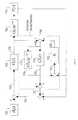
- FIG. 5shows a Laplace representation of a predictive speed controller 16 that uses the ESP 130 and FIG. 6 further describes the operations shown in FIG. 5 .
- the operations 100 - 128are substantially the same as previously described in FIGS. 3 and 4 , but are explained again for completeness.
- the model corrector 132identifies the difference (modeling error) 134 between the predicted vehicle travel speed with time delay 116 and the actual vehicle travel speed 110 for the vehicle 108 .
- the model corrector 132applies the amplified gain K to the modeling error 134 and feeds the amplified modeling error 136 back into both model 112 and model 114 .
- K valueis properly tuned, the output 122 of ESP 130 will asymptotically converge to the time-delay generated output offset, and therefore compensate for the modeling error.
- the predictive speed controller 16 with the Enhanced Smith Predictor (ESP) 130is used to control the engine 24 and the power shift transmission 26 in an industrial vehicle 108 , such as a lift truck.
- an industrial vehicle 108such as a lift truck.
- the ESP 130 described abovecan be used to achieve target behaviors for any physical system that exhibits time delays when executing commands. This could include vehicle or control system that exhibit time delays.
- the desired vehicle travel speed 100may be controlled by a vehicle operator. For example, the vehicle operator may move the position of pedal 11 to change a desired speed for the vehicle 108 .
- the position sensor 14sends a signal corresponding to the pedal position 12 to the predictive speed controller 16 .
- the operations performed by the predictive speed controller 16are carried out by a microcontroller or microprocessor that executes software instructions stored in a storage medium.
- the microprocessor operating predictive speed controller 16converts the foot pedal position signal from position sensor 14 into the desired travel speed 100 .
- the desired travel speed 100is compared with the final predicted travel speed 124 to produce the predicted travel speed tracking error 126 .
- the PI controller 104is another function performed by the microprocessor that generates a desired control force 128 .
- the desired control force 128can be different control signals or data sent to the real-world vehicle system 108 .
- the real-world vehicle system 108may include one or more microcontrollers, valves, power shift transmission 26 , engine 24 , drive axle 34 , and wheels 30 , among other things.
- the control signals corresponding to the desired control force 128are acted upon by the real-world vehicle system 108 to produce the actual vehicle travel speed 110 .
- the speed control information associated with the desired control force 128is also fed into the Enhanced Smith Predictor 130 and combined with the modeling error feedback value 136 generated from the model corrector 132 .
- the sum of the desired control force 128 and the error feedback value 136is input into both mathematical models 112 and 114 .
- the predicted/simulated travel speed with time delay 116is fed into the model corrector 132 .
- the model corrector 132determines the difference 134 between the predicted vehicle travel speed with time delay 116 and the actual vehicle travel speed 110 .
- the model corrector 132then applies a gain value K to the difference 134 to produce the modeling error feedback value 136 .
- the sum of the modeling error feedback value 136 and the desired control force 128works to create the predicted travel speed with time delay 116 that asymptotically converges to the real world vehicle speed 110 , and thereby compensates the modeling error.
- the sum of the desired control force 128 and modeling error feedback value 136is input into both the model 112 and the model 114 .
- the predicted travel speed with time delay 116 from model 112is compared with the predicted travel speed with no time delay 120 from model 114 to produce the time delay compensation value 122 .
- a sum of the time delay compensation value 122 and the actual vehicle travel speed 110is used as the final predicted travel speed 124 .
- the final predicted travel speed 124is then used to offset the actual desired vehicle speed 100 .
- the ESP 130compensates for changes in the desired speed 100 caused by the time delay from when the operator selects a new desired speed 100 to when the industrial vehicle responds to the new selected speed.
- the ESP 130provides a high-performance feedback control design, and therefore, achieves good PBSC performance.
- FIG. 7shows a more detailed example of how the models 112 and 114 are implemented in the ESP 130 of FIG. 6 .
- models 112 and 114are implemented in the ESP 130 of FIG. 6 .
- FIG. 7shows a more detailed example of how the models 112 and 114 are implemented in the ESP 130 of FIG. 6 .
- Other model implementationscould also be used.
- Mthe equivalent mass of the vehicle.
- vvelocity of the vehicle system model.
- the original speed signalis used in place of the predicted signal from the Enhanced Smith Predictor 130 , the P-gain in controller 104 is designed low, and a high I-gain is used to drive the vehicle 108 .
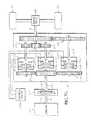
- FIGS. 8A-8Cdescribe in more detail how the predictive speed controller 16 is used in conjunction with a power shift transmission.
- FIG. 8Ashows portions of the vehicle 108 including the power shift transmission 26 connected to the engine 24 by a hydraulic torque converter 206 .
- An output shaft 28 of the transmission 26is connected to the drive axle 34 that drives wheels 30 .
- the power shift transmission 14can also be used in a variety of other vehicles.
- the same microprocessor that operates the predictive speed controller 16may also control activation of a forward clutch pack (FWD) 234 and a reverse clutch pack (REV) 232 in the transmission 26 using any of the predictive speed control schemes described above.
- a control valve 230 in the transmission 26controls fluid pressure that activates the two clutch packets 232 and 234 .
- the controller 16receives vehicle speed and direction signal 110 from the vehicle speed sensor 27 indicating the rotational speed and direction of the axle 28 .
- a converter speed signal 204is generated from a torque converter speed sensor 202 and indicates the rotational speed of an output shaft 246 ( FIG. 8B ) of the torque converter 206 .
- An engine speed signal 214is generated from an engine speed sensor 212 and indicates how fast an output shaft 242 ( FIG. 8B ) of the engine 24 is rotating.
- An engine governor control signal 210controls a throttle valve 208 that controls the speed of engine 24 .
- the controller 16receives the pedal position signal 100 from the position sensor 14 on foot pedal 11 .
- the pedal positioncan alternatively refer to a throttle value, acceleration value, or a deceleration value.
- a forward-reverse direction signal 226is generated by a direction lever or pedal 224 and indicates a forward or backward direction the vehicle operator selects for the vehicle 108 .
- An internal or external memory 222contains mapped parameters identifying clutch pack pressure values and other control parameters used for performing different braking and speed control operations. The controller 16 selects these different pressure values according one or more of the predictive speed control schemes described above.
- the memory 222also contains the predetermined gain values used for correcting error in the prediction models (see FIGS. 2 , 5 , and 6 )
- FIG. 8Bis a more detailed schematic diagram of a single speed power shift transmission.
- the torque converter 206includes an impeller pump 240 and a turbine 244 .
- a shaft 242extends from the impeller pump 240 and is coupled to the crankshaft of engine 24 .
- a shaft 246extends from the turbine 244 and is coupled to the input of power shift transmission 26 .
- the torque converter 206continuously varies the ratio of the speed of the output shaft 246 to the speed of the input shaft 242 in accordance with the load on the output shaft 246 .
- the forward clutch pack 234 and the reverse clutch pack 232each selectively engages and disengages the input shaft 246 with the output shaft 28 through the forward gears 252 and reverse gears 254 .
- the engaging force of the clutches 234 and 232are controlled by changing the oil pressure in oil chambers 234 C and 232 C, respectively.
- the oil pressures provided by the control valve 230is controlled by the desired control force signals 128 generated by the predictive speed controller 16 ( FIG. 8A ).
- the clutch packs 234 and 232are multiple disc hydraulic wet clutches.
- a FWD-1 signal 218 in FIG. 8Acontrols the oil pressure in the forward clutch pack 234 .
- a REV-1 signal 216 in FIG. 8Acontrols the oil pressure in the REV clutch pack 232 .
- the two speed PS transmissionis shown in FIG. 8C and includes two forward gears 260 and 250 and one reverse gear 254 .
- a second forward multiple disk hydraulic wet clutch 262selectively engages and disengages the input shaft 246 with the output shaft 28 through high forward gear 260 .
- the high forward clutch 262When the vehicle 10 is moving in a forward direction at a high speed in high gear 260 , the high forward clutch 262 is partially engaged (not locked) and the low forward clutch 234 and high forward clutch 262 operate as a hydraulic brake.
- the forward low clutch 234When the vehicle 10 is moving in a forward direction at a slower speed, the forward low clutch 234 is partially engaged (not locked) and the reverse clutch 232 and low forward clutch 234 function as a hydraulic brake.
- the reverse clutch 232When the vehicle 10 is moving backward, the reverse clutch 232 is engaged (not locked) and the forward clutch 234 and reverse clutch 232 function as a hydraulic brake.
- the single speed PS transmission in FIG. 8B , the multi-speed PS transmission shown in FIG. 8C , or any other combination of gears and clutch packs,can be controlled using the predictive speed controller 16 as described above in FIGS. 1-7 .
- the predictive speed controller 16provides improved PBSC control of vehicles that use power shift transmissions. Specifically, the predictive speed controller 16 significantly improves travel speed control performance and eliminates abrupt acceleration and deceleration (jerk) due to time delays in vehicle response. In one application, the predictive speed controller 16 allows an operator to control the power shift transmission 26 very much like a highly responsive hydrostatic transmission. As a result, the vehicle 108 provides many of the control benefits of a hydrostatic transmission at the lower cost of a power shift transmission.
- the system described abovecan use dedicated processor systems, micro controllers, programmable logic devices, or microprocessors that perform some or all of the operations. Some of the operations described above may be implemented in software and other operations may be implemented in hardware.
Landscapes
- Engineering & Computer Science (AREA)
- Chemical & Material Sciences (AREA)
- Combustion & Propulsion (AREA)
- Transportation (AREA)
- Mechanical Engineering (AREA)
- Automation & Control Theory (AREA)
- Physics & Mathematics (AREA)
- Evolutionary Computation (AREA)
- Computer Vision & Pattern Recognition (AREA)
- Medical Informatics (AREA)
- Software Systems (AREA)
- Artificial Intelligence (AREA)
- General Physics & Mathematics (AREA)
- Health & Medical Sciences (AREA)
- Mathematical Physics (AREA)
- Human Computer Interaction (AREA)
- Control Of Transmission Device (AREA)
- Control Of Driving Devices And Active Controlling Of Vehicle (AREA)
- Control Of Vehicle Engines Or Engines For Specific Uses (AREA)
Abstract
Description
- 100—R(s) is a reference speed input, which in one embodiment, is the desired speed selected by the operator through the position12 of pedal11 (
FIG. 1 ). s means that the reference input is expressed in Laplace space. This applies to all other places where s appears. - 104—C(s) is the designed controller, which in one embodiment, is a Proportional-Integral (PI) controller. The
controller 104 generates a desiredcontrol force 128 used for controlling the speed ofvehicle 108 inFIG. 1 . - 108—G(s)e−λsis the real-world vehicle system with a real-world time delay. The value λ is the real-world time delay.
- 110—Y(s) is the system output, which in one embodiment, is the vehicle speed measured through an on-board speed sensor27 (
FIG. 1 ). - 112—G′(s)e−λ'sis a mathematical model that simulates the vehicle response with an estimated time delay. The value λ′ is the estimated time delay.
- 114—G′(s) is a model that estimates the vehicle response without the time delay.
- 116—The output of
model 112 is referred to as the predicted travel speed with time delay. - 118—The Smith Predictor includes the
model 112 andmodel 114 and generates an output G′(s)-G′(s)e−λ's. - 120—The output of
model 114 is referred to as the predicted travel speed with no time delay. - 122—The difference between the predicted travel speed with
time delay 116 and the predicted travel speed withouttime delay 120 is referred to as thetime delay compensation 122. Thetime delay compensation 122 is essentially a prediction of changes to the vehicle speed caused by time delays in the vehicle response. - 124—The final predicted travel speed combines the
actual travel speed 110 with thetime delay compensation 122. - 126—The predicted travel speed tracking error is the difference between the desired
speed 100 and the final predictedtravel speed 124. - 128—The desired control force corresponds to one or more control signals or control data output by the
controller 104 to control the speed of vehicle108 (FIG. 1 ).
- 100—R(s) is a reference speed input, which in one embodiment, is the desired speed selected by the operator through the position12 of pedal11 (
- 100—R(s) is a reference speed input, which in one embodiment is the desired speed selected by the operator through the position12 of pedal11 (
FIG. 1 ). s means that the reference input is expressed in Laplace space. This applies to all other places where s appears. - 104—C(s) is a Proportional-Integral (PI) controller. The
controller 104 generates a desired control force106 used for controlling the speed ofvehicle 108. - 108—G(s)e−λsis the real-world vehicle system with a real-world time delay. The value λ is the real-world time delay.
- 110—Y(s) is the system output, which in one embodiment is the vehicle speed measured through on-board speed sensor27 (
FIG. 1 ). - 112—G′(s)e−λ'sis a mathematical model that simulates the vehicle response with an estimated time delay λ′. In one embodiment, a mass/viscous-damper system is used as the
vehicle system model 112. - 114—G′(s) is a model that estimates the vehicle response without the time delay. As mentioned above, a mass/viscous-damper system could be used as the
vehicle system model 114. - 116—The output of
model 112 is referred to as the predicted travel speed with time delay. - 118—The Enhanced Smith Predictor includes the
model 112 andmodel 114, which can be written as G′(s)-G′(s)e−λ's. - 120—The output of
model 114 is referred to as the predicted travel speed with no time delay. - 122—The difference between the predicted travel speed with
delay 116 and the predicted travel speed withoutdelay 120 is again referred to as thetime delay compensation 122. - 124—The final predicted travel speed combines the
actual travel speed 110 with thetime delay compensation 122. - 126—The predicted travel speed tracking error is the difference between the desired
speed 100 and the final predicted travel speed. - 128—The desired control force corresponds to one or more control signals or data generated by the
controller 104 to control the speed of vehicle108 (FIG. 1 ). - 130—The Enhanced Smith Predictor (ESP) includes
model 112,model 114, and amodel corrector 132. - 132—The model corrector applies gain value K to a
modeling error 124. The gain value K is derived through experiments and saved in the look-up table44 previously shown inFIG. 2 . - 134—The difference value between the predicted vehicle travel speed with
time delay 116 and the actualvehicle travel speed 110. - 136—The modeling error feedback from the
model corrector 132. - 138—The sum of
control force 128 and themodeling error feedback 136. Thevalue 138 is used for driving bothmodels actual speed 110.
- 100—R(s) is a reference speed input, which in one embodiment is the desired speed selected by the operator through the position12 of pedal11 (
- 128—The control force is the signal or information output by the
controller 104 inFIG. 6 and is used for controlling the speed of vehicle108 (FIG. 2 ). As explained above, in one embodiment thecontroller 104 is a Proportional-Integral (PI) controller. - 110—The actual vehicle travel speed is reported by an on-board speed sensor27 (
FIG. 2 ). - 114—This
vehicle model 114 uses a simplified mass/viscous-damper model to estimate the vehicle response with no time delay. Themodel 112 with time delay is achieved by applying atime delay 156 serially to the output of the non-time delayedvehicle model 114.
- 128—The control force is the signal or information output by the
M{dot over (v)}+Cv=F
- 122—The time delay compensation value is the difference between the two
vehicle system models - 124—The predicted vehicle speed is the summation of the actual vehicle speed and the time delay compensation value. This predicted vehicle speed is a predictor of what speed the vehicle operator actually intended to select.
- 132—The mode corrector uses the lookup table44 (
FIG. 2 ) to store the modeling error correction gains, K. Due to the nonlinearity of the vehicle dynamics, different gains are used with different vehicle speeds. These gains are derived offline from empirical data to ensure themodel corrector 132 converges faster than the vehicle system dynamics, so that a converged observation can be used in the control system. - 150—Equivalent vehicle mass. In order to minimize the modeling error in all kinds of working conditions, the equivalent vehicle mass is derived as the summation of the vehicle translation inertia, the vehicle rotational inertia, and half of the vehicle workload capacity.
- 154—Equivalent damping coefficient. Following the same principle of minimizing the modeling error, the equivalent damping coefficient is estimated with a half-loaded vehicle operating at a constant travel speed (0 acceleration) of 6 mph (median speed) on a level surface. The value of the damping
coefficient 154 is the average control force divided by the travel speed. - 152—The discrete integrator converts the acceleration signal into an estimated speed value output by the
model 114. - 156—As mentioned above, the
time delay 156 is used to create thevehicle model 112 with time delay.
- 122—The time delay compensation value is the difference between the two
Claims (24)
Priority Applications (3)
| Application Number | Priority Date | Filing Date | Title |
|---|---|---|---|
| US12/256,445US8135531B2 (en) | 2002-06-12 | 2008-10-22 | Predictive vehicle controller |
| EP08167535.7AEP2052925B1 (en) | 2007-10-26 | 2008-10-24 | Predictive vehicle controller |
| EP17182190.3AEP3275750A1 (en) | 2007-10-26 | 2008-10-24 | Predictive vehicle controller |
Applications Claiming Priority (7)
| Application Number | Priority Date | Filing Date | Title |
|---|---|---|---|
| US38853302P | 2002-06-12 | 2002-06-12 | |
| US10/209,444US6684148B2 (en) | 2002-06-12 | 2002-07-30 | Transmission control system |
| US10/689,812US6950737B2 (en) | 2002-06-12 | 2003-10-20 | Transmission control system |
| US58098804P | 2004-06-18 | 2004-06-18 | |
| US11/516,913US7974760B2 (en) | 2003-10-20 | 2006-09-06 | Advanced power-shift transmission control system |
| US98301807P | 2007-10-26 | 2007-10-26 | |
| US12/256,445US8135531B2 (en) | 2002-06-12 | 2008-10-22 | Predictive vehicle controller |
Related Parent Applications (1)
| Application Number | Title | Priority Date | Filing Date |
|---|---|---|---|
| US11/516,913Continuation-In-PartUS7974760B2 (en) | 2002-06-12 | 2006-09-06 | Advanced power-shift transmission control system |
Publications (2)
| Publication Number | Publication Date |
|---|---|
| US20090048748A1 US20090048748A1 (en) | 2009-02-19 |
| US8135531B2true US8135531B2 (en) | 2012-03-13 |
Family
ID=40229934
Family Applications (1)
| Application Number | Title | Priority Date | Filing Date |
|---|---|---|---|
| US12/256,445Expired - Fee RelatedUS8135531B2 (en) | 2002-06-12 | 2008-10-22 | Predictive vehicle controller |
Country Status (2)
| Country | Link |
|---|---|
| US (1) | US8135531B2 (en) |
| EP (2) | EP3275750A1 (en) |
Cited By (28)
| Publication number | Priority date | Publication date | Assignee | Title |
|---|---|---|---|---|
| US20120001578A1 (en)* | 2010-07-02 | 2012-01-05 | Lsis Co., Ltd. | Inverter for electric vehicle |
| US9120658B2 (en)* | 2013-12-27 | 2015-09-01 | Komatsu Ltd. | Forklift and control method of forklift |
| US9187093B1 (en) | 2014-08-04 | 2015-11-17 | Cummins, Inc. | Systems and methods of cruise droop control |
| US10882399B2 (en) | 2005-11-17 | 2021-01-05 | Invently Automotive Inc. | Electric vehicle power management system |
| US10919409B2 (en) | 2005-11-17 | 2021-02-16 | Invently Automotive Inc. | Braking power management |
| US11084377B2 (en) | 2005-11-17 | 2021-08-10 | Invently Automotive Inc. | Vehicle power management system responsive to voice commands from a Gps enabled device |
| US11180025B2 (en) | 2005-11-17 | 2021-11-23 | Invently Automotive Inc. | Electric vehicle power management system |
| US11186175B2 (en) | 2005-11-17 | 2021-11-30 | Invently Automotive Inc. | Vehicle power management system |
| US11186174B2 (en) | 2005-11-17 | 2021-11-30 | Invently Automotive Inc. | Vehicle power management system |
| US11186173B2 (en) | 2005-11-17 | 2021-11-30 | Invently Automotive Inc. | Electric vehicle power management system |
| US11207980B2 (en) | 2005-11-17 | 2021-12-28 | Invently Automotive Inc. | Vehicle power management system responsive to traffic conditions |
| US11207981B2 (en) | 2005-11-17 | 2021-12-28 | Invently Automotive Inc. | Vehicle power management system |
| US11214144B2 (en) | 2005-11-17 | 2022-01-04 | Invently Automotive Inc. | Electric vehicle power management system |
| US11220179B2 (en) | 2005-11-17 | 2022-01-11 | Invently Automotive Inc. | Vehicle power management system determining route segment length |
| US11225144B2 (en) | 2005-11-17 | 2022-01-18 | Invently Automotive Inc. | Vehicle power management system |
| US11230190B2 (en) | 2005-11-17 | 2022-01-25 | Invently Automotive Inc. | Electric vehicle power management system |
| US11247564B2 (en) | 2005-11-17 | 2022-02-15 | Invently Automotive Inc. | Electric vehicle power management system |
| US11254211B2 (en) | 2005-11-17 | 2022-02-22 | Invently Automotive Inc. | Electric vehicle power management system |
| US11267339B2 (en) | 2005-11-17 | 2022-03-08 | Invently Automotive Inc. | Vehicle power management system |
| US11267338B2 (en) | 2005-11-17 | 2022-03-08 | Invently Automotive Inc. | Electric vehicle power management system |
| US11279233B2 (en) | 2005-11-17 | 2022-03-22 | Invently Automotive Inc. | Electric vehicle power management system |
| US11279234B2 (en) | 2005-11-17 | 2022-03-22 | Invently Automotive Inc. | Vehicle power management system |
| US11285810B2 (en) | 2005-11-17 | 2022-03-29 | Invently Automotive Inc. | Vehicle power management system |
| US11325468B2 (en) | 2005-11-17 | 2022-05-10 | Invently Automotive Inc. | Vehicle power management system |
| US11345236B2 (en) | 2005-11-17 | 2022-05-31 | Invently Automotive Inc. | Electric vehicle power management system |
| US11351863B2 (en) | 2005-11-17 | 2022-06-07 | Invently Automotive Inc. | Vehicle power management system |
| US11370302B2 (en) | 2005-11-17 | 2022-06-28 | Invently Automotive Inc. | Electric vehicle power management system |
| US11390165B2 (en) | 2005-11-17 | 2022-07-19 | Invently Automotive Inc. | Electric vehicle power management system |
Families Citing this family (24)
| Publication number | Priority date | Publication date | Assignee | Title |
|---|---|---|---|---|
| US8041492B2 (en)* | 2006-10-31 | 2011-10-18 | Clark Equipment Company | Engine load management for power machines |
| ES2370806T3 (en)* | 2007-02-12 | 2011-12-22 | Saab Ab | CONTROL SYSTEM OF A VEHICLE AND PROCEDURE THAT USES THE CONTROL ASSIGNMENT AND PHASE COMPENSATION. |
| US20100125347A1 (en)* | 2008-11-19 | 2010-05-20 | Harris Corporation | Model-based system calibration for control systems |
| US20100123618A1 (en)* | 2008-11-19 | 2010-05-20 | Harris Corporation | Closed loop phase control between distant points |
| US8170088B2 (en)* | 2008-11-19 | 2012-05-01 | Harris Corporation | Methods for determining a reference signal at any location along a transmission media |
| US20100124263A1 (en)* | 2008-11-19 | 2010-05-20 | Harris Corporation | Systems for determining a reference signal at any location along a transmission media |
| US7970365B2 (en)* | 2008-11-19 | 2011-06-28 | Harris Corporation | Systems and methods for compensating for transmission phasing errors in a communications system using a receive signal |
| US7969358B2 (en)* | 2008-11-19 | 2011-06-28 | Harris Corporation | Compensation of beamforming errors in a communications system having widely spaced antenna elements |
| US8457827B1 (en)* | 2012-03-15 | 2013-06-04 | Google Inc. | Modifying behavior of autonomous vehicle based on predicted behavior of other vehicles |
| IL224273B (en)* | 2013-01-17 | 2018-05-31 | Cohen Yossi | Delay compensation while controlling a remote sensor |
| US10386796B2 (en)* | 2014-12-11 | 2019-08-20 | University Of New Brunswick | Model predictive controller and method with correction parameter to compensate for time lag |
| FR3039130B1 (en) | 2015-07-21 | 2019-05-31 | Airbus Operations | METHOD AND DEVICE FOR AUTOMATICALLY MANAGING A ACTUATOR CONTROLLED BY A SERVO-VALVE |
| CN107614345B (en)* | 2015-07-31 | 2020-05-22 | 日立汽车系统株式会社 | Parking assist device for vehicle |
| DE102015223611B4 (en)* | 2015-11-27 | 2023-11-02 | Bayerische Motoren Werke Aktiengesellschaft | Method and control unit for acceleration monitoring and adjustment |
| DE102015015923A1 (en)* | 2015-12-09 | 2017-06-14 | Wabco Gmbh | Method for adaptively controlling a vehicle speed in a vehicle and cruise control system for carrying out the method |
| WO2017210901A1 (en)* | 2016-06-08 | 2017-12-14 | 驭势科技(北京)有限公司 | Speed planning method and apparatus and calculating apparatus for automatic driving of vehicle |
| CN107264510B (en)* | 2017-06-16 | 2019-12-27 | 湖南大学 | Vehicle power control system and method based on traffic jam condition |
| AT519547B1 (en)* | 2017-06-22 | 2018-08-15 | Avl List Gmbh | Device and method for the predictive control of the speed of a vehicle |
| DE102017010180B3 (en) | 2017-10-30 | 2019-04-04 | Daimler Ag | Method and device for controlling a longitudinal position of a vehicle |
| FR3090546B1 (en)* | 2018-12-21 | 2020-12-18 | Psa Automobiles Sa | OSCILLATION DAMPING CONTROL SYSTEM IN A THERMAL MOTOR DRIVE CHAIN |
| CN109634120B (en)* | 2018-12-26 | 2022-06-03 | 东软集团(北京)有限公司 | Vehicle control method and device |
| CN112987555B (en)* | 2019-12-12 | 2022-10-11 | 天津大学 | Composite anti-interference track tracking control algorithm for retreating process of unmanned rolling machine |
| US11453409B2 (en)* | 2020-04-21 | 2022-09-27 | Baidu Usa Llc | Extended model reference adaptive control algorithm for the vehicle actuation time-latency |
| CN116603142A (en)* | 2023-05-24 | 2023-08-18 | 北京瑞承天启医疗科技有限公司 | Oxygen concentration control method for breathing machine and breathing machine |
Citations (71)
| Publication number | Priority date | Publication date | Assignee | Title |
|---|---|---|---|---|
| GB1050283A (en) | 1900-01-01 | |||
| GB663704A (en) | 1948-12-30 | 1951-12-27 | Borg Warner | Improvements in or relating to transmissions for automotive vehicles |
| GB717868A (en) | 1952-04-07 | 1954-11-03 | Gen Motors Corp | Improved variable-speed power transmission mechanism for motor vehicles |
| GB730576A (en) | 1951-05-01 | 1955-05-25 | Gen Tire & Rubber Co | Torque transmitting devices such as clutches or brakes |
| GB803667A (en) | 1954-10-14 | 1958-10-29 | Borg Warner | Improvements in or relating to control for change-speed transmission |
| GB807395A (en) | 1956-06-21 | 1959-01-14 | Gen Motors Corp | Improved control system for variable-speed power transmission mechanism for motor vehicles |
| GB863815A (en) | 1958-04-25 | 1961-03-29 | Gen Motors Corp | Improved control systems for variable-speed power transmission mechanisms |
| GB931262A (en) | 1960-12-17 | 1963-07-17 | Zahnradfabrik Friedrichshafen | Improvements in or relating to hydro-mechanical transmission particularly for motor vehicles |
| GB974481A (en) | 1960-08-15 | 1964-11-04 | Caterpillar Tractor Co | Variable-speed transmission system and hydraulic controls therefor |
| GB1010876A (en) | 1962-10-12 | 1965-11-24 | Ford Motor Co | Motor vehicle automatic transmission |
| GB1017626A (en) | 1962-04-23 | 1966-01-19 | Borg Warner | Manual and automatic change-speed transmission |
| GB1028889A (en) | 1963-12-31 | 1966-05-11 | Ford Motor Co | Automatic change speed transmission |
| US3442152A (en) | 1964-06-18 | 1969-05-06 | Gen Motors Corp | Transmission and controls |
| GB1236040A (en) | 1967-12-22 | 1971-06-16 | Nissan Motor | Hydraulic control system for automatic transmission |
| JPS4869951A (en) | 1971-12-28 | 1973-09-22 | ||
| GB1331352A (en) | 1970-08-24 | 1973-09-26 | Twin Disc Inc | Vehicles having fluid power control systems |
| GB1337712A (en) | 1971-05-26 | 1973-11-21 | Gen Motors Corp | Transmission controls |
| US3893552A (en) | 1973-10-05 | 1975-07-08 | Horton Mfg Co Inc | Clutch and brake with interlock valves |
| GB1520100A (en) | 1976-04-14 | 1978-08-02 | Twin Disc Inc | Transmission control system for shuttle type vehicles |
| US4129148A (en) | 1977-06-30 | 1978-12-12 | International Harvester Company | Clutch modulator |
| US4144863A (en) | 1976-08-23 | 1979-03-20 | Ford Motor Company | Circuit for controlling the operability of one or more cylinders of a multicylinder internal combustion engine |
| EP0010950A1 (en) | 1978-10-30 | 1980-05-14 | A.B. Volvo | Retarding means for motor vehicles |
| DE3135055A1 (en) | 1981-09-04 | 1983-04-07 | Jörg Prof. Dipl.-Ing. 7072 Heubach Linser | Brake/clutch combination |
| US4574927A (en) | 1983-12-19 | 1986-03-11 | Clark Michigan Company | Forward and reverse clutch engagement parking brake |
| EP0299235A2 (en) | 1987-07-16 | 1989-01-18 | Toyota Jidosha Kabushiki Kaisha | Speed control system for a vehicle |
| US4838622A (en) | 1987-05-22 | 1989-06-13 | Alfred Teves Gmbh | Brake system with anti-lock control and/or traction slip control as well as braking pressure modulator for such a brake system |
| JPH01240350A (en) | 1988-03-23 | 1989-09-25 | Kubota Ltd | vehicle braking system |
| JPH037625A (en) | 1989-06-02 | 1991-01-14 | Mitsubishi Motors Corp | Automatic driving control device for vehicles |
| US5048655A (en) | 1990-05-22 | 1991-09-17 | Deere & Company | Electric declutch mechanism for direct drive crawler |
| JPH03292456A (en) | 1990-04-10 | 1991-12-24 | Toyota Motor Corp | Shift controlling method of automatic transmission for vehicle |
| JPH04134141A (en) | 1990-09-26 | 1992-05-08 | Mazda Motor Corp | Controller for vehicle |
| JPH04140567A (en) | 1990-10-02 | 1992-05-14 | Honda Motor Co Ltd | Vehicle automatic transmission control device |
| JPH04325733A (en) | 1991-04-25 | 1992-11-16 | Fuji Heavy Ind Ltd | Engine control device for vehicle with automatic transmission |
| GB2262818A (en) | 1991-12-24 | 1993-06-30 | Ricardo International Plc | Vibration reduced speed control |
| JPH0634027A (en) | 1992-07-10 | 1994-02-08 | Nippondenso Co Ltd | Friction transmission with torque detecting function |
| JPH06247190A (en) | 1993-02-26 | 1994-09-06 | Komatsu Forklift Co Ltd | Cargo handling and running control device for industrial vehicle |
| DE4321413A1 (en) | 1993-06-26 | 1995-01-05 | Bosch Gmbh Robert | Method and device for controlling the drive power of a vehicle |
| US5568378A (en) | 1994-10-24 | 1996-10-22 | Fisher-Rosemount Systems, Inc. | Variable horizon predictor for controlling dead time dominant processes, multivariable interactive processes, and processes with time variant dynamics |
| FR2739064A1 (en) | 1995-09-22 | 1997-03-28 | Renault | METHOD FOR LIMITING THE TORQUE OF AN AUTOMATIC TRANSMISSION |
| GB2322457A (en) | 1997-02-21 | 1998-08-26 | Nissan Motor | Engine control system which reduces thermal deterioration of a torque converter |
| US5833210A (en) | 1995-04-20 | 1998-11-10 | Midwest Brake Bond Company | Brake and clutch control system |
| US5868214A (en)* | 1995-08-29 | 1999-02-09 | Cummins Engine Company, Inc. | Cruise control governor using optimal droop selection logic |
| JPH1178617A (en) | 1997-09-05 | 1999-03-23 | Nissan Motor Co Ltd | Integrated control system for engine and automatic transmission |
| US5901059A (en) | 1996-09-13 | 1999-05-04 | Honeywell Measurex Corp | Method and apparatus for controlling a process using adaptive prediction feedback |
| US5918509A (en) | 1995-05-16 | 1999-07-06 | Zf Friedrichshafen Ag | Powershift reversing transmission |
| JP3007625B1 (en) | 1998-12-10 | 2000-02-07 | 日本アンテナ株式会社 | Bidirectional amplifier with monitor terminal |
| EP1031487A2 (en) | 1999-02-24 | 2000-08-30 | Kabushiki Kaisha Toyoda Jidoshokki Seisakusho | Parking brake apparatus for industrial vehicle |
| US6186029B1 (en) | 1997-07-09 | 2001-02-13 | Dana Corporation | Dual input transmission |
| EP1093986A2 (en) | 1999-10-18 | 2001-04-25 | Kabushiki Kaisha Toyoda Jidoshokki Seisakusho | Driving control apparatus for industrial vehicle |
| JP2001116070A (en) | 1999-10-18 | 2001-04-27 | Toyota Autom Loom Works Ltd | Braking control device for industrial vehicle |
| US6335609B1 (en) | 2000-05-09 | 2002-01-01 | Ford Global Technologies, Inc. | Method for reducing peak phase current and decreasing staring time for an internal combustion engine having an induction machine |
| US6424902B1 (en)* | 2000-10-30 | 2002-07-23 | Caterpillar Inc. | Method and apparatus for operating a continuously variable transmission in the torque limited region near zero output speed |
| US20020107111A1 (en) | 2001-02-07 | 2002-08-08 | Exedy Corporation | Vehicle auxiliary braking system |
| JP2002363038A (en) | 2000-12-22 | 2002-12-18 | Shiseido Co Ltd | Cosmetic |
| JP2002367299A (en) | 2001-06-07 | 2002-12-20 | Sony Corp | Feed mechanism of optical pickup and disk driver |
| JP2003182408A (en) | 2001-12-21 | 2003-07-03 | Toyota Motor Corp | Control device for automatic transmission |
| US20030209047A1 (en) | 2002-05-07 | 2003-11-13 | Nelepovitz Donald Owen | Die apparatus and method for high temperature forming of metal products |
| EP1371513A2 (en) | 2002-06-12 | 2003-12-17 | Nacco Materials Handling Group Inc. | Transmission control system |
| WO2005021315A1 (en) | 2003-08-27 | 2005-03-10 | Volvo Lastvagnar Ab | Method and arrangement for controlling actual torque in a land vehicle driveline |
| US6901324B2 (en) | 2003-09-30 | 2005-05-31 | Caterpillar Inc | System and method for predictive load management |
| US20050245351A1 (en) | 2004-04-27 | 2005-11-03 | Denso Corporation | Controller for automatic transmission |
| US7006909B1 (en) | 2004-10-20 | 2006-02-28 | Detroit Diesel Corporation | Engine delay compensation |
| US7146263B2 (en) | 2003-09-30 | 2006-12-05 | Caterpillar Inc | Predictive load management system |
| US7153235B2 (en) | 2003-03-17 | 2006-12-26 | Komatsu Forklift Co., Ltd. | Running control device for industrial vehicle |
| US20060293822A1 (en) | 2005-06-27 | 2006-12-28 | Freightliner Llc | Predictive control method and apparatus for vehicle automatic transmission |
| US20070010927A1 (en) | 2003-10-20 | 2007-01-11 | Nmhg Oregon, Inc. | Advanced power-shift transmission control system |
| JP4134141B2 (en) | 2005-10-20 | 2008-08-13 | 株式会社ジェイワンホーム | Floor concrete level construction method and level indicator |
| JP4140567B2 (en) | 2004-07-14 | 2008-08-27 | 松下電器産業株式会社 | Object tracking device and object tracking method |
| US7524268B2 (en) | 2005-09-30 | 2009-04-28 | Kabushiki Kaisha Toyota Jidoshokki | Drive control apparatus for forklift |
| JP4325733B2 (en) | 2005-02-28 | 2009-09-02 | 三菱化学株式会社 | Phosphor, manufacturing method thereof, and light emitting device using the same |
| JP4869951B2 (en) | 2005-01-19 | 2012-02-08 | オリンパス株式会社 | Medical device data analyzer |
- 2008
- 2008-10-22USUS12/256,445patent/US8135531B2/ennot_activeExpired - Fee Related
- 2008-10-24EPEP17182190.3Apatent/EP3275750A1/ennot_activeWithdrawn
- 2008-10-24EPEP08167535.7Apatent/EP2052925B1/ennot_activeNot-in-force
Patent Citations (75)
| Publication number | Priority date | Publication date | Assignee | Title |
|---|---|---|---|---|
| GB1050283A (en) | 1900-01-01 | |||
| GB663704A (en) | 1948-12-30 | 1951-12-27 | Borg Warner | Improvements in or relating to transmissions for automotive vehicles |
| GB730576A (en) | 1951-05-01 | 1955-05-25 | Gen Tire & Rubber Co | Torque transmitting devices such as clutches or brakes |
| GB717868A (en) | 1952-04-07 | 1954-11-03 | Gen Motors Corp | Improved variable-speed power transmission mechanism for motor vehicles |
| GB803667A (en) | 1954-10-14 | 1958-10-29 | Borg Warner | Improvements in or relating to control for change-speed transmission |
| GB807395A (en) | 1956-06-21 | 1959-01-14 | Gen Motors Corp | Improved control system for variable-speed power transmission mechanism for motor vehicles |
| GB863815A (en) | 1958-04-25 | 1961-03-29 | Gen Motors Corp | Improved control systems for variable-speed power transmission mechanisms |
| GB974481A (en) | 1960-08-15 | 1964-11-04 | Caterpillar Tractor Co | Variable-speed transmission system and hydraulic controls therefor |
| GB931262A (en) | 1960-12-17 | 1963-07-17 | Zahnradfabrik Friedrichshafen | Improvements in or relating to hydro-mechanical transmission particularly for motor vehicles |
| GB1017626A (en) | 1962-04-23 | 1966-01-19 | Borg Warner | Manual and automatic change-speed transmission |
| GB1010876A (en) | 1962-10-12 | 1965-11-24 | Ford Motor Co | Motor vehicle automatic transmission |
| GB1028889A (en) | 1963-12-31 | 1966-05-11 | Ford Motor Co | Automatic change speed transmission |
| US3442152A (en) | 1964-06-18 | 1969-05-06 | Gen Motors Corp | Transmission and controls |
| GB1236040A (en) | 1967-12-22 | 1971-06-16 | Nissan Motor | Hydraulic control system for automatic transmission |
| GB1331352A (en) | 1970-08-24 | 1973-09-26 | Twin Disc Inc | Vehicles having fluid power control systems |
| GB1337712A (en) | 1971-05-26 | 1973-11-21 | Gen Motors Corp | Transmission controls |
| JPS4869951A (en) | 1971-12-28 | 1973-09-22 | ||
| US3893552A (en) | 1973-10-05 | 1975-07-08 | Horton Mfg Co Inc | Clutch and brake with interlock valves |
| GB1520100A (en) | 1976-04-14 | 1978-08-02 | Twin Disc Inc | Transmission control system for shuttle type vehicles |
| US4144863A (en) | 1976-08-23 | 1979-03-20 | Ford Motor Company | Circuit for controlling the operability of one or more cylinders of a multicylinder internal combustion engine |
| US4129148A (en) | 1977-06-30 | 1978-12-12 | International Harvester Company | Clutch modulator |
| EP0010950A1 (en) | 1978-10-30 | 1980-05-14 | A.B. Volvo | Retarding means for motor vehicles |
| DE3135055A1 (en) | 1981-09-04 | 1983-04-07 | Jörg Prof. Dipl.-Ing. 7072 Heubach Linser | Brake/clutch combination |
| US4574927A (en) | 1983-12-19 | 1986-03-11 | Clark Michigan Company | Forward and reverse clutch engagement parking brake |
| US4838622A (en) | 1987-05-22 | 1989-06-13 | Alfred Teves Gmbh | Brake system with anti-lock control and/or traction slip control as well as braking pressure modulator for such a brake system |
| EP0299235A2 (en) | 1987-07-16 | 1989-01-18 | Toyota Jidosha Kabushiki Kaisha | Speed control system for a vehicle |
| JPH01240350A (en) | 1988-03-23 | 1989-09-25 | Kubota Ltd | vehicle braking system |
| JPH037625A (en) | 1989-06-02 | 1991-01-14 | Mitsubishi Motors Corp | Automatic driving control device for vehicles |
| JPH03292456A (en) | 1990-04-10 | 1991-12-24 | Toyota Motor Corp | Shift controlling method of automatic transmission for vehicle |
| US5048655A (en) | 1990-05-22 | 1991-09-17 | Deere & Company | Electric declutch mechanism for direct drive crawler |
| JPH04134141A (en) | 1990-09-26 | 1992-05-08 | Mazda Motor Corp | Controller for vehicle |
| JPH04140567A (en) | 1990-10-02 | 1992-05-14 | Honda Motor Co Ltd | Vehicle automatic transmission control device |
| JPH04325733A (en) | 1991-04-25 | 1992-11-16 | Fuji Heavy Ind Ltd | Engine control device for vehicle with automatic transmission |
| GB2262818A (en) | 1991-12-24 | 1993-06-30 | Ricardo International Plc | Vibration reduced speed control |
| JPH0634027A (en) | 1992-07-10 | 1994-02-08 | Nippondenso Co Ltd | Friction transmission with torque detecting function |
| JPH06247190A (en) | 1993-02-26 | 1994-09-06 | Komatsu Forklift Co Ltd | Cargo handling and running control device for industrial vehicle |
| DE4321413A1 (en) | 1993-06-26 | 1995-01-05 | Bosch Gmbh Robert | Method and device for controlling the drive power of a vehicle |
| US5568378A (en) | 1994-10-24 | 1996-10-22 | Fisher-Rosemount Systems, Inc. | Variable horizon predictor for controlling dead time dominant processes, multivariable interactive processes, and processes with time variant dynamics |
| US5833210A (en) | 1995-04-20 | 1998-11-10 | Midwest Brake Bond Company | Brake and clutch control system |
| US5918509A (en) | 1995-05-16 | 1999-07-06 | Zf Friedrichshafen Ag | Powershift reversing transmission |
| US5868214A (en)* | 1995-08-29 | 1999-02-09 | Cummins Engine Company, Inc. | Cruise control governor using optimal droop selection logic |
| FR2739064A1 (en) | 1995-09-22 | 1997-03-28 | Renault | METHOD FOR LIMITING THE TORQUE OF AN AUTOMATIC TRANSMISSION |
| US5901059A (en) | 1996-09-13 | 1999-05-04 | Honeywell Measurex Corp | Method and apparatus for controlling a process using adaptive prediction feedback |
| GB2322457A (en) | 1997-02-21 | 1998-08-26 | Nissan Motor | Engine control system which reduces thermal deterioration of a torque converter |
| US6186029B1 (en) | 1997-07-09 | 2001-02-13 | Dana Corporation | Dual input transmission |
| JPH1178617A (en) | 1997-09-05 | 1999-03-23 | Nissan Motor Co Ltd | Integrated control system for engine and automatic transmission |
| JP3007625B1 (en) | 1998-12-10 | 2000-02-07 | 日本アンテナ株式会社 | Bidirectional amplifier with monitor terminal |
| EP1031487A2 (en) | 1999-02-24 | 2000-08-30 | Kabushiki Kaisha Toyoda Jidoshokki Seisakusho | Parking brake apparatus for industrial vehicle |
| EP1093986A2 (en) | 1999-10-18 | 2001-04-25 | Kabushiki Kaisha Toyoda Jidoshokki Seisakusho | Driving control apparatus for industrial vehicle |
| JP2001116070A (en) | 1999-10-18 | 2001-04-27 | Toyota Autom Loom Works Ltd | Braking control device for industrial vehicle |
| US6335609B1 (en) | 2000-05-09 | 2002-01-01 | Ford Global Technologies, Inc. | Method for reducing peak phase current and decreasing staring time for an internal combustion engine having an induction machine |
| US6424902B1 (en)* | 2000-10-30 | 2002-07-23 | Caterpillar Inc. | Method and apparatus for operating a continuously variable transmission in the torque limited region near zero output speed |
| JP2002363038A (en) | 2000-12-22 | 2002-12-18 | Shiseido Co Ltd | Cosmetic |
| US20020107111A1 (en) | 2001-02-07 | 2002-08-08 | Exedy Corporation | Vehicle auxiliary braking system |
| JP2002235846A (en) | 2001-02-07 | 2002-08-23 | Exedy Corp | Auxiliary braking system for vehicle |
| JP2002367299A (en) | 2001-06-07 | 2002-12-20 | Sony Corp | Feed mechanism of optical pickup and disk driver |
| JP2003182408A (en) | 2001-12-21 | 2003-07-03 | Toyota Motor Corp | Control device for automatic transmission |
| US20030209047A1 (en) | 2002-05-07 | 2003-11-13 | Nelepovitz Donald Owen | Die apparatus and method for high temperature forming of metal products |
| EP1371513A2 (en) | 2002-06-12 | 2003-12-17 | Nacco Materials Handling Group Inc. | Transmission control system |
| US6684148B2 (en) | 2002-06-12 | 2004-01-27 | Nacco Materials Handling Group, Inc. | Transmission control system |
| US7153235B2 (en) | 2003-03-17 | 2006-12-26 | Komatsu Forklift Co., Ltd. | Running control device for industrial vehicle |
| WO2005021315A1 (en) | 2003-08-27 | 2005-03-10 | Volvo Lastvagnar Ab | Method and arrangement for controlling actual torque in a land vehicle driveline |
| US7146263B2 (en) | 2003-09-30 | 2006-12-05 | Caterpillar Inc | Predictive load management system |
| US6901324B2 (en) | 2003-09-30 | 2005-05-31 | Caterpillar Inc | System and method for predictive load management |
| US20070010927A1 (en) | 2003-10-20 | 2007-01-11 | Nmhg Oregon, Inc. | Advanced power-shift transmission control system |
| US7974760B2 (en) | 2003-10-20 | 2011-07-05 | Nmhg Oregon, Inc. | Advanced power-shift transmission control system |
| US20050245351A1 (en) | 2004-04-27 | 2005-11-03 | Denso Corporation | Controller for automatic transmission |
| US20070179017A1 (en) | 2004-04-27 | 2007-08-02 | Denso Corporation | Controller for automatic transmission |
| JP4140567B2 (en) | 2004-07-14 | 2008-08-27 | 松下電器産業株式会社 | Object tracking device and object tracking method |
| US7006909B1 (en) | 2004-10-20 | 2006-02-28 | Detroit Diesel Corporation | Engine delay compensation |
| JP4869951B2 (en) | 2005-01-19 | 2012-02-08 | オリンパス株式会社 | Medical device data analyzer |
| JP4325733B2 (en) | 2005-02-28 | 2009-09-02 | 三菱化学株式会社 | Phosphor, manufacturing method thereof, and light emitting device using the same |
| US20060293822A1 (en) | 2005-06-27 | 2006-12-28 | Freightliner Llc | Predictive control method and apparatus for vehicle automatic transmission |
| US7524268B2 (en) | 2005-09-30 | 2009-04-28 | Kabushiki Kaisha Toyota Jidoshokki | Drive control apparatus for forklift |
| JP4134141B2 (en) | 2005-10-20 | 2008-08-13 | 株式会社ジェイワンホーム | Floor concrete level construction method and level indicator |
Non-Patent Citations (18)
| Title |
|---|
| Cooksley, "Stepless Changes", IVT Int'l, Issue Feb. 2001, 3 pgs. |
| Dicks, "Drive through hydrostatics", IVT '99-Lift Truck & Materials Handling, pp. 65-68. |
| Dicks, "Drive through hydrostatics", IVT '99—Lift Truck & Materials Handling, pp. 65-68. |
| European Patent Office, European Search Report for EP02255419.0, Apr. 1, 2004, 5 pages. |
| European Patent Office, Examination Report for EP02255419.0, Nov. 2, 2005, 4 pages. |
| European Patent Office, Extended European Search Report for EP08000084.7, Feb. 21, 2008, 6 pages. |
| European Patent Office, Supplemental Examination Report for EP02255419.0, Jul. 18, 2008, 4 pages. |
| European Patent Office, Supplementary Search Report for EP05766042; Aug. 31, 2011, 3 pages. |
| European Patent Office; European Search Report for EP08167535; Aug. 2, 2010. |
| Failing, Braking in the Wet, IVT Int'l, 2002, pp. 117-118. |
| Meinke et al., "Breaking News", IVT Int'l, 2002, 4 pgs. |
| Scheffels, "Electronics on the advance", IVT Europe, Issue 3, Jul. 1998, 5 pgs. |
| Scheffels, "Hydraulics-the advantages of electronics", IVT Europe, Mar. 1998, 5 pgs. |
| Scheffels, "Hydraulics—the advantages of electronics", IVT Europe, Mar. 1998, 5 pgs. |
| Scheffels, "Transmission: auto, manual or both", IVT Int'l, Issue Feb. 2000, 3 pgs. |
| Stolowitz Ford Cowger LLP, "Listing of Related Cases", Nov. 29, 2011, 2 pages. |
| Taylor et al., "Electronic hydrostatics-the future of transmissions", IVT-Materials Handling, Jan. 1998, 3 pgs. |
| Taylor et al., "Electronic hydrostatics—the future of transmissions", IVT—Materials Handling, Jan. 1998, 3 pgs. |
Cited By (29)
| Publication number | Priority date | Publication date | Assignee | Title |
|---|---|---|---|---|
| US11220179B2 (en) | 2005-11-17 | 2022-01-11 | Invently Automotive Inc. | Vehicle power management system determining route segment length |
| US11267339B2 (en) | 2005-11-17 | 2022-03-08 | Invently Automotive Inc. | Vehicle power management system |
| US11390165B2 (en) | 2005-11-17 | 2022-07-19 | Invently Automotive Inc. | Electric vehicle power management system |
| US11370302B2 (en) | 2005-11-17 | 2022-06-28 | Invently Automotive Inc. | Electric vehicle power management system |
| US10882399B2 (en) | 2005-11-17 | 2021-01-05 | Invently Automotive Inc. | Electric vehicle power management system |
| US10919409B2 (en) | 2005-11-17 | 2021-02-16 | Invently Automotive Inc. | Braking power management |
| US11084377B2 (en) | 2005-11-17 | 2021-08-10 | Invently Automotive Inc. | Vehicle power management system responsive to voice commands from a Gps enabled device |
| US11180025B2 (en) | 2005-11-17 | 2021-11-23 | Invently Automotive Inc. | Electric vehicle power management system |
| US11186175B2 (en) | 2005-11-17 | 2021-11-30 | Invently Automotive Inc. | Vehicle power management system |
| US11186174B2 (en) | 2005-11-17 | 2021-11-30 | Invently Automotive Inc. | Vehicle power management system |
| US11186173B2 (en) | 2005-11-17 | 2021-11-30 | Invently Automotive Inc. | Electric vehicle power management system |
| US11207980B2 (en) | 2005-11-17 | 2021-12-28 | Invently Automotive Inc. | Vehicle power management system responsive to traffic conditions |
| US11207981B2 (en) | 2005-11-17 | 2021-12-28 | Invently Automotive Inc. | Vehicle power management system |
| US11214144B2 (en) | 2005-11-17 | 2022-01-04 | Invently Automotive Inc. | Electric vehicle power management system |
| US11351863B2 (en) | 2005-11-17 | 2022-06-07 | Invently Automotive Inc. | Vehicle power management system |
| US11230190B2 (en) | 2005-11-17 | 2022-01-25 | Invently Automotive Inc. | Electric vehicle power management system |
| US11345236B2 (en) | 2005-11-17 | 2022-05-31 | Invently Automotive Inc. | Electric vehicle power management system |
| US11247564B2 (en) | 2005-11-17 | 2022-02-15 | Invently Automotive Inc. | Electric vehicle power management system |
| US11254211B2 (en) | 2005-11-17 | 2022-02-22 | Invently Automotive Inc. | Electric vehicle power management system |
| US11225144B2 (en) | 2005-11-17 | 2022-01-18 | Invently Automotive Inc. | Vehicle power management system |
| US11267338B2 (en) | 2005-11-17 | 2022-03-08 | Invently Automotive Inc. | Electric vehicle power management system |
| US11279233B2 (en) | 2005-11-17 | 2022-03-22 | Invently Automotive Inc. | Electric vehicle power management system |
| US11279234B2 (en) | 2005-11-17 | 2022-03-22 | Invently Automotive Inc. | Vehicle power management system |
| US11285810B2 (en) | 2005-11-17 | 2022-03-29 | Invently Automotive Inc. | Vehicle power management system |
| US11325468B2 (en) | 2005-11-17 | 2022-05-10 | Invently Automotive Inc. | Vehicle power management system |
| US20120001578A1 (en)* | 2010-07-02 | 2012-01-05 | Lsis Co., Ltd. | Inverter for electric vehicle |
| US8461791B2 (en)* | 2010-07-02 | 2013-06-11 | Lsis Co., Ltd. | Inverter for electric vehicle |
| US9120658B2 (en)* | 2013-12-27 | 2015-09-01 | Komatsu Ltd. | Forklift and control method of forklift |
| US9187093B1 (en) | 2014-08-04 | 2015-11-17 | Cummins, Inc. | Systems and methods of cruise droop control |
Also Published As
| Publication number | Publication date |
|---|---|
| US20090048748A1 (en) | 2009-02-19 |
| EP2052925B1 (en) | 2017-08-30 |
| EP2052925A2 (en) | 2009-04-29 |
| EP3275750A1 (en) | 2018-01-31 |
| EP2052925A3 (en) | 2010-09-08 |
Similar Documents
| Publication | Publication Date | Title |
|---|---|---|
| US8135531B2 (en) | Predictive vehicle controller | |
| US7908066B2 (en) | Powertrain of a motor vehicle and method for controlling said powertrain | |
| US8892315B2 (en) | Method of controlling a continuously variable transmission | |
| US8715136B1 (en) | Torque converter slip control based on motor torque during transient events | |
| US6299563B1 (en) | Control system for hybrid vehicle | |
| US6679807B2 (en) | Vehicle driving control device and method | |
| KR101724913B1 (en) | Control method of dual clutch transmission for hybrid electric vehicle and control system for the same | |
| JP5026188B2 (en) | Vehicle control device and vehicle control system | |
| US9879769B2 (en) | Torque converter clutch slip control | |
| JPWO2012133059A1 (en) | Shift control device for hybrid vehicle | |
| US20100185375A1 (en) | Acceleration control apparatus for vehicle | |
| KR100779175B1 (en) | Power train control device in vehicle integrated control system | |
| WO2007049784A1 (en) | Controller of vehicle | |
| US20120017578A1 (en) | Power transfer system | |
| WO2014135831A2 (en) | Vehicle clutch control systems | |
| KR100886738B1 (en) | Hybrid drive device and its regulating method and engine coltrolling appatatus, and computer program recorder | |
| JP2019536674A (en) | Torque or power monitor | |
| US20150166067A1 (en) | System and method for controlling the speed of an engine | |
| JP2007163306A (en) | Automatic operation control device for vehicle tester | |
| US9079574B2 (en) | Method for controlling a motor vehicle powertrain | |
| JP7036341B2 (en) | Hybrid vehicle control device | |
| JP7036342B2 (en) | Hybrid vehicle control device | |
| US11835131B2 (en) | Control apparatus for vehicle | |
| JP2006266315A (en) | Control device for starting friction element | |
| Parlapanis et al. | Feed-Forward Control of a Construction Vehicle's Hydro-Mechanical Powertrain to Prevent Engine Stalling |
Legal Events
| Date | Code | Title | Description |
|---|---|---|---|
| AS | Assignment | Owner name:NMHG OREGON, LLC, OREGON Free format text:ASSIGNMENT OF ASSIGNORS INTEREST;ASSIGNORS:ZHAO, SIDE;CHEN, CHENYAO;REEL/FRAME:021742/0711 Effective date:20081022 | |
| AS | Assignment | Owner name:CITICORP NORTH AMERICA, INC.,NEW YORK Free format text:SECURITY AGREEMENT;ASSIGNOR:NMHG OREGON, LLC;REEL/FRAME:024626/0783 Effective date:20100630 Owner name:CITICORP NORTH AMERICA, INC., NEW YORK Free format text:SECURITY AGREEMENT;ASSIGNOR:NMHG OREGON, LLC;REEL/FRAME:024626/0783 Effective date:20100630 | |
| ZAAA | Notice of allowance and fees due | Free format text:ORIGINAL CODE: NOA | |
| ZAAB | Notice of allowance mailed | Free format text:ORIGINAL CODE: MN/=. | |
| STCF | Information on status: patent grant | Free format text:PATENTED CASE | |
| AS | Assignment | Owner name:BANK OF AMERICA, N.A., AS ADMINISTRATIVE AGENT, TE Free format text:NOTICE OF GRANT OF SECURITY INTEREST IN PATENTS;ASSIGNOR:NMHG OREGON, LLC;REEL/FRAME:028445/0171 Effective date:20120622 | |
| CC | Certificate of correction | ||
| AS | Assignment | Owner name:NMHG OREGON, LLC, OHIO Free format text:RELEASE BY SECURED PARTY;ASSIGNOR:BANK OF AMERICA, N.A.;REEL/FRAME:031862/0216 Effective date:20131218 | |
| FPAY | Fee payment | Year of fee payment:4 | |
| AS | Assignment | Owner name:HYSTER-YALE GROUP INC., OREGON Free format text:ASSIGNMENT OF ASSIGNORS INTEREST;ASSIGNOR:NMHG OREGON, LLC;REEL/FRAME:038771/0288 Effective date:20160520 | |
| AS | Assignment | Owner name:BANK OF AMERICA, N.A., AS ADMINISTRATIVE AGENT, ILLINOIS Free format text:NOTICE OF GRANT OF SECURITY INTEREST IN PATENTS;ASSIGNORS:HYSTER-YALE GROUP, INC.;HYSTER-YALE MATERIALS HANDLING, INC.;HYSTER OVERSEAS CAPITAL CORPORATION, LLC;AND OTHERS;REEL/FRAME:042624/0838 Effective date:20170530 Owner name:BANK OF AMERICA, N.A., AS ADMINISTRATIVE AGENT, IL Free format text:NOTICE OF GRANT OF SECURITY INTEREST IN PATENTS;ASSIGNORS:HYSTER-YALE GROUP, INC.;HYSTER-YALE MATERIALS HANDLING, INC.;HYSTER OVERSEAS CAPITAL CORPORATION, LLC;AND OTHERS;REEL/FRAME:042624/0838 Effective date:20170530 | |
| MAFP | Maintenance fee payment | Free format text:PAYMENT OF MAINTENANCE FEE, 8TH YEAR, LARGE ENTITY (ORIGINAL EVENT CODE: M1552); ENTITY STATUS OF PATENT OWNER: LARGE ENTITY Year of fee payment:8 | |
| AS | Assignment | Owner name:BANK OF AMERICA, N.A. (A NATIONAL BANKING INSTITUTION), ILLINOIS Free format text:SECURITY INTEREST;ASSIGNORS:HYSTER-YALE GROUP, INC. (A DELAWARE CORPORATION);NUVERA FUEL CELLS, LLC (A DELAWARE LIMITED LIABILITY COMPANY);REEL/FRAME:057013/0037 Effective date:20210624 | |
| FEPP | Fee payment procedure | Free format text:MAINTENANCE FEE REMINDER MAILED (ORIGINAL EVENT CODE: REM.); ENTITY STATUS OF PATENT OWNER: LARGE ENTITY | |
| LAPS | Lapse for failure to pay maintenance fees | Free format text:PATENT EXPIRED FOR FAILURE TO PAY MAINTENANCE FEES (ORIGINAL EVENT CODE: EXP.); ENTITY STATUS OF PATENT OWNER: LARGE ENTITY | |
| STCH | Information on status: patent discontinuation | Free format text:PATENT EXPIRED DUE TO NONPAYMENT OF MAINTENANCE FEES UNDER 37 CFR 1.362 | |
| FP | Lapsed due to failure to pay maintenance fee | Effective date:20240313 | |
| AS | Assignment | Owner name:HYSTER-YALE MATERIALS HANDLING, INC., OREGON Free format text:CHANGE OF NAME;ASSIGNOR:HYSTER-YALE GROUP, INC.;REEL/FRAME:067661/0617 Effective date:20240606 |