US8135273B2 - Systems and methods of optical path protection for distributed antenna systems - Google Patents
Systems and methods of optical path protection for distributed antenna systemsDownload PDFInfo
- Publication number
- US8135273B2 US8135273B2US12/862,042US86204210AUS8135273B2US 8135273 B2US8135273 B2US 8135273B2US 86204210 AUS86204210 AUS 86204210AUS 8135273 B2US8135273 B2US 8135273B2
- Authority
- US
- United States
- Prior art keywords
- optical signal
- fiber
- downlink
- uplink
- optical
- Prior art date
- Legal status (The legal status is an assumption and is not a legal conclusion. Google has not performed a legal analysis and makes no representation as to the accuracy of the status listed.)
- Expired - Fee Related
Links
Images


Classifications
- H—ELECTRICITY
- H04—ELECTRIC COMMUNICATION TECHNIQUE
- H04B—TRANSMISSION
- H04B10/00—Transmission systems employing electromagnetic waves other than radio-waves, e.g. infrared, visible or ultraviolet light, or employing corpuscular radiation, e.g. quantum communication
- H04B10/25—Arrangements specific to fibre transmission
- H04B10/2575—Radio-over-fibre, e.g. radio frequency signal modulated onto an optical carrier
- H04B10/25752—Optical arrangements for wireless networks
- H—ELECTRICITY
- H04—ELECTRIC COMMUNICATION TECHNIQUE
- H04B—TRANSMISSION
- H04B10/00—Transmission systems employing electromagnetic waves other than radio-waves, e.g. infrared, visible or ultraviolet light, or employing corpuscular radiation, e.g. quantum communication
- H04B10/11—Arrangements specific to free-space transmission, i.e. transmission through air or vacuum
- H04B10/112—Line-of-sight transmission over an extended range
- H04B10/1123—Bidirectional transmission
- H04B10/1127—Bidirectional transmission using two distinct parallel optical paths
Definitions
- Fiber breaks and/or degradation in a fiber feeding a distributed antenna system (DAS) networkcan have a large impact on a system's availability.
- Network operatorstypically look for a high-degree of network availability (for example, “0.9999” or higher).
- a network availability of 0.9999requires a network be unavailable for no more than 1 hour per year, whereas a network availability of 0.99999 requires a network be unavailable for no more than 1 hour every ten years.
- One fiber break that causes a DAS network to be unavailable for 10 hours while the fiber break is isolated and repairedwould lower availability to 0.999. Oftentimes fiber breaks take even longer to isolate and repair.
- Adverse changes to a fiber-based networkcan happen in many different ways. Examples include digging near fiber optic cabling that causes damage to fiber, damaging the cable by a maintenance worker stepping on, bending, or breaking a fiber. Aerial-mounted fiber can be damaged during accidents involving the poles hanging the fiber. Optical connectors can become degraded by damage and/or dirt. These are just a few of the fiber degradation scenarios, any of which can cause degraded or loss of service on that fiber for extended periods of time. Due to the time required to isolate and repair fibers, redundant paths are often used in order to keep the system up as much as possible. Since fiber damage tends to be a local event, redundant fibers are usually run via completely different paths. In this way, any local damage done to the fiber does not affect the redundant path.
- both a hub and remote node connected by the redundant fibersincludes active switching devices in order to switch from a primary fiber to a secondary fiber in the event of a break (or other degradation of the primary fiber).
- remote nodesare often located in isolated areas with limited power resources and space for accommodating optical switching equipment.
- a systemcomprising a hub; at least one remote node that is located remotely from the hub; wherein the hub communicates with the at least one remote node via either one of a primary fiber path and a backup fiber path, the primary fiber path comprising an uplink fiber and a downlink fiber and the backup fiber path comprising an uplink fiber and a downlink fiber; wherein the at least one remote node is coupled to the downlink fiber of the primary fiber path and the downlink fiber of the backup fiber path via an optical combiner; wherein the at least one remote node is further coupled to the uplink fiber of the primary fiber path and the uplink fiber of the backup fiber path via an optical splitter; and wherein the hub switches from communicating with the at least one remote node on the primary fiber path to communicating with the at least one remote node on the backup fiber path based on an uplink optical signal received from the at least one remote node.
- a methodcomprises receiving an electrical uplink radio frequency signal; generating an uplink optical signal derived from the electrical uplink radio frequency signal; splitting the uplink optical signal for transmission on a primary uplink optical fiber and a secondary uplink optical fiber; combining any downlink optical signal received on a primary downlink optical communication medium and any downlink optical signal received on a second downlink optical communication medium in order to output a downlink optical signal; and generating a downlink radio frequency signal derived from the downlink optical signal.
- an apparatuscomprises means for receiving an electrical uplink radio frequency signal; means for generating an uplink optical signal derived from the electrical uplink radio frequency signal; means for splitting the uplink optical signal for transmission on a primary uplink optical fiber and a secondary uplink optical fiber; means for combining any downlink optical signal received on the primary downlink optical communication medium and any downlink optical signal received on the second downlink optical communication medium in order to output a downlink optical signal; and means for generating a downlink radio frequency signal derived from the downlink optical signal.
- FIG. 1is a block diagram of one embodiment of a distributed antenna system.
- FIG. 2is a block diagram of one embodiment of a distributed antenna system.
- FIG. 3Ais a block diagram of one embodiment of a distributed antenna system.
- FIG. 3Bis a block diagram of one embodiment of a distributed antenna system.
- FIG. 4is a flow chart of a one embodiment of a method of providing passive optical path protection.
- FIG. 5is a block diagram of one embodiment of a distributed antenna system.
- FIG. 1is a block diagram of one embodiment of a distributed antenna system (DAS) 100
- DAS 100is often used in a wireless communication network (for example, a cellular wireless network) to communicatively couple one or more base stations (not shown in FIG. 1 ) to one or more antennas that are remotely located from the base stations (not shown in FIG. 1 ).
- DAS 100includes a hub 110 located near the base stations and one or more remote access nodes 130 (also referred to here as “remote nodes” 130 ), each of which is located near one or more remote antennas (for example, a primary and diversity antenna).
- the DAS 100comprises a single hub 110 that is optically coupled to single remote node 130 (though it is to be understood that in other embodiments other numbers of hubs 110 and/or remote nodes 130 are used).
- the hub 110is optically coupled to the remote node 130 through a primary optical fiber path 120 and a backup optical fiber path 125 .
- primary optical fiber path 120includes a primary downlink optical fiber 122 and a primary uplink optical fiber 124 .
- Backup optical fiber path 125includes a secondary downlink optical fiber 127 and a secondary uplink optical fiber 129 .
- one or both of primary optical fiber path 120 and backup optical fiber path 125include a plurality of uplink and/or downlink optical fibers.
- Hub 110comprises interface functionality 111 that couple the hub 110 to one or more base stations, a fiber optic transceiver 112 communicatively coupled to the one or more interface functionality 111 , an optical switch 114 communicatively coupled to the fiber optic transceiver 112 , primary optical fiber path 120 and backup optical fiber path 125 , and a hub optical path protection (OPP) manager 116 communicatively coupled to the fiber optic transceiver 112 and the optical switch 114 .
- OPPhub optical path protection
- the interface functionality 111 of the hub 110receives analog downlink RF signals from the one or more base stations to which the hub 110 is communicatively coupled and provide the fiber optical transceiver 112 a suitable electrical signal for modulating onto a downlink optical carrier.
- the downlink optical signal output by the fiber optic transceiver 112is selectively communicated to the remote node 130 on either the primary downlink optical fiber 122 or secondary downlink optical fiber 127 by the optical switch 114 , depending on a fiber path control signal output by the hub optical path protection manager 116 .
- the interface functionality 111receives one or more analog downlink radio frequency (RF) signals from each of the base stations to which the hub 110 is communicatively coupled and digitizes at least a portion of the received analog downlink RF signal (for example, by digitizing a particular frequency band of the received analog downlink RF signal).
- RFradio frequency
- the interface functionality 111combines at least a portion of the digitized downlink RF signals from one or more base stations into frames suitable for transmission on the primary downlink optical fiber 122 and/or the secondary downlink optical fiber 127 (for example, by formatting the at least a portion of the digitized downlink RF signals into SONET STS-48/OC-48 formatted frames).
- the fiber optic transceiver 112digitally modulates the electrical signal (which comprises frames of digitized downlink RF signals) onto a downlink optical carrier in order to generate the downlink optical signal.
- An example of downlink functionality suitable for use in such a digital-transport implementationis described in U.S. Pat. No. 6,963,552, titled “MULTI-PROTOCOL DISTRIBUTED WIRELESS SYSTEM ARCHITECTURE” (also referred to here as the “'552 Patent”), which is hereby incorporated herein by reference.
- the interface functionality 111receives one or more analog downlink RF signals from each of the base stations to which the hub 110 is communicatively coupled and filters, combines, mixes, and/or splits the received analog downlink RF signals into a single electrical analog signal suitable for transmission on the primary downlink optical fiber 122 and/or the secondary downlink optical fiber 127 .
- the fiber optic transceiver 112amplitude modulates the single electrical analog signal received from the interface functionality 111 onto a downlink optical carrier in order to generate the downlink optical signal.
- hub 110receives an uplink optical signal from the remote node 130 on both of the primary uplink optical fiber 124 and the secondary uplink optical fiber 129 .
- Optical switch 114selectively couples one of the primary uplink optical fiber 124 and the secondary uplink optical fiber 129 to the fiber optic transceiver 112 , depending on the fiber path control signal from the hub optical path protection manager 116 . That is, when optical switch 114 selectively couples the primary uplink optical fiber 124 to the fiber optical transceiver 112 , any uplink optical signal received on the primary uplink optical fiber 124 is communicated to the fiber optic transceiver 112 by the optical switch.
- any uplink optical signal received on the secondary uplink optical fiber 129is communicated to the fiber optic transceiver 112 by the optical switch.
- the fiber optic transceiver 112demodulates the uplink optical signal in order to extract an electrical uplink RF signal, which is provided to one or more base stations via the interface functionality 111 .
- the extracted uplink RF signalcomprises frames (for example, SONET STS-48/OC-48 formatted frames) containing digitized uplink RF signals, which the interface functionality 111 extracts from the frames and converts to analog uplink RF signals.
- the analog uplink RF signalsare provided to one or more base stations coupled to the hub 110 .
- the extracted uplink RF signalcomprises an analog uplink RF signals that are provided to one or more base stations coupled to the hub 110 .
- Remote node 130comprises an optical combiner 134 , an optical splitter 135 , a fiber optic transceiver 132 , interface functionality 133 , and a remote optical path protection (OPP) manager 136 .
- OPPremote optical path protection
- the optical combiner 134 of the remote node 130receives downlink optical signals from hub 110 via one of either primary downlink optical fiber 122 or secondary downlink optical fiber 127 .
- An optical “combiner”, as the term is used in this specification,means a device that receives a plurality of optical signal inputs and combines the optical signals into a single optical output.
- the downlink optical signalis transmitted on only one of the primary downlink optical fiber 122 or the secondary downlink optical fiber 127 at any one time. For this reason, at any one time, only the selected one of the primary downlink optical fiber 122 or the secondary downlink optical fiber 127 is “lit” while the fiber not selected by optical switch 114 is “dark” and does not carry an optical signal.
- optical combiner 134This eliminates concerns of optical interference at the optical combiner 134 .
- the resulting output of optical combiner 134which is essentially the combination of the downlink optical signal from the lit fiber with a null signal from the dark fiber, is thus simply the downlink optical signal.
- the output of the optical combiner 134(that is, the downlink optical signal) is communicated via a single fiber to fiber optic transceiver 132 .
- the fiber optic transceiver 132demodulates the downlink optical signal in order to extract an electrical downlink RF signal, which is provided to one or more antennas 140 and 141 via the interface functionality 133 .
- the electrical downlink RF signal output by the fiber optic transceiver 132comprises digitized downlink RF signals from one or more base stations.
- the interface functionality 133converts the digitized downlink RF signals into analog downlink RF signals (for example, using a suitable digital-to-analog conversion process), which are amplified for radiation from the one or more antennas 140 and 141 .
- the digitized downlink RF signals from each of the base stationsis separately converted into an individual analog downlink RF signal for that respective base station (for example, by respective “RAN slices” of the type described in the '552 Patent) and each of the individual analog downlink RF signals are thereafter combined for amplification and radiation from one or more of the antennas 140 and 141 .
- the electrical downlink RF signal output by the fiber optic transceiver 132comprises analog downlink RF signals from one or more of base stations and the interface functionality 133 amplifies for radiation from the one or more antennas 140 and 141 .
- the interface functionality 133 of the remote node 130receives analog uplink RF signals from the one or more antennas 140 and 141 coupled to the remote node 130 .
- the interface functionality 133provides the fiber optical transceiver 132 a suitable electrical signal for modulating onto an uplink optical carrier.
- the uplink optical signal output by the fiber optic transceiver 132is communicated on both of primary uplink optical fiber 124 and secondary uplink optical fiber 129 by the optical splitter 135 .
- An optical “splitter”, as the term is used in this specification,means a device that replicates an optical signal received at an input to each of a plurality of outputs.
- optical splitter 135optically replicates the uplink optical signal output by the fiber optic transceiver 132 so that the uplink optical signal is communicated to hub 110 via both of the primary uplink optical fiber 124 and the secondary uplink optical fiber 129 .
- the interface functionality 133 of the remote node 130receives one or more analog uplink RF signals from each of the antennas 140 and 141 to which the remote node 130 is communicatively coupled and digitizes at least a portion of the received analog uplink RF signal (for example, by digitizing a particular frequency band of each analog uplink RF signal).
- the interface functionality 133combines at least a portion of the digitized uplink RF signals from one or more of the antennas 140 and 141 into frames suitable for transmission on the primary uplink optical fiber 124 and the secondary uplink optical fiber 129 (for example, by formatting the at least a portion of the digitized uplink RF signals into SONET STS-48/OC-48 formatted frames).
- the fiber optic transceiver 132digitally modulates the electrical signal (which comprises frames of digitized uplink RF signals) onto an uplink optical carrier in order to generate the uplink optical signal.
- the interface functionality 133receives one or more analog uplink RF signals from each of the antennas 140 and 141 to which the remote node 130 is communicatively coupled and filters, combines, mixes, and/or splits the received analog uplink RF signals into a single analog signal suitable for transmission on the primary uplink optical fiber 124 and the secondary uplink optical fiber 129 .
- the fiber optic transceiver 132amplitude modulates the single electrical analog signal received from the interface functionality 133 onto an uplink optical carrier in order to generate the uplink optical signal, which is then communicated to the hub 110 on both the primary uplink optical fiber 124 and the secondary uplink optical fiber 129 via the splitter 135 .
- the hub OPP manager (HOM) 116determines when communications between hub 110 and remote node 130 via the primary fiber path 120 are within acceptable operating parameters. When HOM 116 determines that primary fiber path 120 is operating within acceptable operating parameters HOM 116 causes optical switch 114 to align itself for transmitting the downlink optical signal via the primary downlink optical fiber 122 and receiving the uplink optical signal from the primary uplink optical fiber 124 (the “normal state” of optical switch 114 ).
- HOM 116determines that communications via primary fiber path 120 are not within acceptable operating parameters, HOM 116 causes optical switch 114 to align itself for transmitting the downlink optical signal via the secondary downlink optical fiber 127 and to align itself for receiving the uplink optical signal from the secondary uplink optical fiber 129 (the “backup state” of optical switch 114 ).
- HOM 116determines when communications via primary fiber path 120 are not within acceptable operating parameters based on the uplink optical signal received on the primary uplink optical fiber 124 .
- fiber optic transceiver 112communicates an uplink signal quality signal to HOM 116 (or other information indicative of an attribute of the uplink optical signal).
- HOM 116switches optical switch 114 from its normal state to the backup state in order to utilize backup fiber path 125 .
- fiber optic transceiver 112communicates the bit error ratio (BER) of the uplink optical signal it receives. In such an implementation, when the BER drops below a predetermined threshold BER, HOM 116 switches optical switch 114 from its normal state to the backup state in order to utilize backup fiber path 125 .
- BERbit error ratio
- a typical good fiber pathperforms at better than a 10e-12 BER. Because of the amount of over-sampling typically used in such a digital-transport implementation, an optical fiber path can continue to operate down to as low as 10e-6 BER without adversely affecting call quality.
- other signal quality indicatorssuch as but not limited to optical power levels, are used to determine whether or not communications via primary fiber path 120 are within acceptable operating parameters.
- fiber optic transceiver 112measures and communicates the optical power level of the uplink optical signal it receives. In such an implementation, when the optical power level drops below a predetermined threshold power level, HOM 116 switches optical switch 114 from its normal state to the backup state in order to utilize backup fiber path 125 .
- HOM 116cannot directly determine the signal quality of downlink optical signals received by remote node 130 . Therefore, information regarding the signal quality of downlink optical signals is communicated to HOM 116 by remote OPP manager (ROM) 136 . In other embodiments, other information indicative of an attribute of the downlink optical signal is determined and communicated.
- ROMremote OPP manager
- fiber optic transceiver 132receives the downlink optical signal and communicates a downlink signal quality signal to ROM 136 .
- fiber optic transceiver 132communicates the bit error rate (BER) of the downlink optical signal it receives to ROM 136 .
- BERbit error rate
- ROM 136reports the BER to HOM 116 so that HOM 116 can make the determination on whether to switch from the primary fiber path 120 to the backup fiber path 125 .
- other signal quality indicatorsare used to determine whether or not communications via primary fiber path 120 are within acceptable operating parameters.
- HOM 116switches optical switch 114 from its normal state to the backup state in order to utilize backup fiber path 125 .
- fiber optic transceiver 132measures and communicates the optical power level of the downlink optical signal it receives.
- ROM 136reports the optical power level to HOM 116 so that HOM 116 can make the determination on whether to switch from the primary fiber path 120 to the backup fiber path 125 .
- fiber optic transceiver 112measures and communicates the optical power level of the uplink optical signal it receives while fiber optic transceiver 132 communicates the bit error rate (BER) of the downlink optical signal it receives.
- fiber optic transceiver 112communicates the bit error rate (BER) of the uplink optical signal it receives while fiber optic transceiver 132 communicates the optical power level of the downlink optical signal it receives.
- ROM 136makes the determination whether to switch communications from the primary fiber path 120 to the backup fiber path 125 based on the signal quality of the downlink optical signal, and alerts HOM 116 of a degraded downlink fiber path by shutting off the uplink fiber path.
- ROM 136disables fiber optic transceiver 132 from transmitting the uplink optical signal to hub 110 .
- ROM 136disables fiber optic transceiver 132 from transmitting the uplink optical signal to hub 110 .
- Fiber optic transceiver 112detects this loss of the uplink optical signal and outputs an uplink signal quality signal that indicates the loss of the uplink optical signal.
- HOM 116responds to what it perceives as a degraded uplink signal quality by switching optical switch 114 from its normal state to the backup state in order to utilize backup fiber path 125 .
- the hub 110contains all of the “active” optical path protection circuitry (that is, the optical switch 114 ) that is used to switch among the redundant fiber paths.
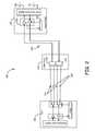
- the remote node 130includes passive optical splitters and combiners that typically do not require significant space to install (space often being a scarce resource at remote node locations) and typically do not require addition power to operate (power often being a scarce resource at remote node locations). Further, when space is very limited within a remote node, the optical splitter and optical combiner need not be located within the remote node housing, but can be installed external to the remote node housing, as illustrated in the embodiment shown in FIG. 2 . FIG.
- Hub 210illustrates a hub 210 coupled to an optical combiner 234 and an optical splitter 235 via a primary optical fiber path 220 and a backup fiber path 225 .
- Hub 210operates as described with respect to hub 110 shown in FIG. 1 , transmitting downlink optical signals to optical combiner 234 and receiving uplink optical signals from optical splitter 235 .
- optical combiner 234 and optical splitter 235are located in a housing 215 that is external to remote node 230 .
- Optical combiner 234 and optical splitter 235are coupled to the fiber optic transceiver 232 within remote node 230 via fiber pair 220 .
- housing 215may comprise an underground cable vault or similar location where power is not available. Further, only a single fiber pair 220 needs to be run between housing 215 and the remote node 230 , thus reducing system installation costs.
- a ROM 236 , interface functionality 233 , and fiber optic transceiver 232 within remote node 230otherwise operate as described with respect to ROM 136 , interface functionality 133 , and fiber optic transceiver 132 in FIG. 1 .
- the approach shown in FIG. 2is also suitable for use in “retro-fitting” or “aftermarket” applications where a service provider desires to add optical path protection for deployed remote nodes that are not designed to house an optical combiner or an optical splitter.
- the functionality of the ROMis implemented in an element management system that is otherwise coupled to the remote nodes, and the protection switching performed by the optical switch in the respective hub is controlled by communications from the element management system that is otherwise communicatively coupled to the hub.
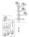
- hub 310communicates with a plurality of remote nodes 330 - 1 to 330 -N via multiple wavelength optical signals.
- Hub 310includes the functionality required to multiplex multiple optical carrier signals from a communications network (not shown) onto a single optical fiber by using different wavelengths of light to carry a plurality of different RF signals.
- Hub 310comprises interface functionality 311 - 1 to 311 - x that couple the hub 310 to one or more base stations (not shown).
- the hub 310further comprises fiber optic transceivers 312 - 1 to 312 - x communicatively coupled, respectively, to the interface functionality 311 - 1 to 311 - x , and wave division multiplexing (WDM) multiplexer (MUX) 313 communicatively coupled to the downlink output of fiber optical transceivers 312 - 1 to 312 - x .
- the hub 310further comprises a WDM DE-MUX 315 communicatively coupled to the uplink inputs of optical transceivers 312 - 1 to 312 - x and an optical switch 314 communicatively coupled to WDM MUX 313 , WDM DE-MUX 315 , primary optical fiber path 320 and backup optical fiber path 325 .
- the hub 310further comprises a hub optical path protection manager (HOM) 316 communicatively coupled to fiber optic transceivers 312 - 1 to 312 - x and optical switch 314 .
- HOMhub optical path protection manager
- the interface functionality 311 - 1 to 311 - xreceives analog downlink RF signals from the one or more base stations to which the hub 310 is communicatively coupled and provides to the fiber optical transceivers 312 - 1 to 312 - x , respectively, a suitable electrical signal for modulating onto a downlink optical carrier.
- the fiber optical transceivers 312 - 1 to 312 - xmodulate the electrical signal onto a different downlink optical carrier.
- the downlink optical signal d 1 , d 2 , to dx output by each of the fiber optic transceivers 312 - 1 to 312 - xis optically multiplexed by WDM MUX 313 into a single downlink multiple wavelength optical signal (shown as d 1 +d 2 +. . . +dx).
- the downlink multiple wavelength optical signal output by WDM MUX 313is selectively communicated to the remote node 330 on either the primary downlink optical fiber 322 or secondary downlink optical fiber 327 by the optical switch 314 , depending on a fiber path control signal output by the hub optical path protection manager 316 .
- the interface functionality 311 - 1 to 311 - xreceives one or more analog downlink radio frequency (RF) signals from each of the base stations to which the hub 310 is communicatively coupled and digitizes at least a portion of the received analog downlink RF signals (for example, by digitizing a particular frequency band of each received analog downlink RF signal).
- RFradio frequency
- each item of interface functionality 311 - 1 to 311 - xcombines at least a portion of the digitized downlink RF signals from one or more base stations into frames suitable for transmission on the primary downlink optical fiber 322 or the secondary downlink optical fiber 327 (for example, by formatting the at least a portion of the digitized downlink RF signals into SONET STS-48/OC-48 formatted frames).
- the fiber optic transceivers 312 - 1 to 312 - xeach digitally modulate the electrical signal (which comprises frames of digitized downlink RF signals) onto a respective downlink optical carrier.
- All of the downlink optical signals output by the fiber optic transceivers 312 - 1 to 312 - xare multiplexed together by the WDM MUX 313 .
- An example of downlink functionality suitable for use in such a digital-transport implementationis described in U.S. Pat. No. 6,963,552, titled “MULTI-PROTOCOL DISTRIBUTED WIRELESS SYSTEM ARCHITECTURE” (also referred to here as the “'552 Patent”), which is hereby incorporated herein by reference.
- the interface functionality 311 - 1 to 311 - xeach receives one or more analog downlink RF signals from each of the base stations to which the hub 310 is communicatively coupled and filters, combines, mixes, and/or splits the received analog downlink RF signals into a single electrical analog signal suitable for transmission on the primary downlink optical fiber 322 and/or the secondary downlink optical fiber 327 .
- the fiber optic transceivers 312 - 1 to 312 - xeach amplitude modulate the single electrical analog signal received from the respective items of interface functionality 311 - 1 to 311 - x onto a respective downlink optical carrier in order to generate the respective downlink optical signal.
- All of the downlink optical signals output by the fiber optic transceivers 312 - 1 to 312 - xare multiplexed together by the WDM MUX 313 .
- the downlink output of hub 310is coupled to the remote nodes 330 - 1 to 330 -N via a cable vault 331 that is remotely located from the hub 310 and proximal to the first remote node 330 - 1 .
- the cable vault 331comprises an optical combiner 334 that has two inputs that are coupled to the primary downlink optical fiber 322 and the secondary downlink optical fiber 327 .
- Optical switch 314outputs the downlink multiple wavelength optical signal on either the primary downlink optical fiber 322 or the secondary downlink optical fiber 327 , depending on the fiber path control signal from the hub optical path protection manager 316 .
- hub 310receives an uplink multiple wavelength optical signal via one or both of primary uplink optical fiber 324 and secondary uplink optical fiber 329 from an optical splitter 335 that is also housed within the cable vault 331 .
- the uplink multiple wavelength optical signalcomprises multiplexed uplink optical signals (shown as u 1 , u 2 , . . . ux) from the remote nodes 330 - 1 to 330 -N.
- Optical switch 314selectively couples one of the primary uplink optical fiber 324 and the secondary uplink optical fiber 329 to the WDM DE-MUX 315 , depending on the fiber path control signal from the hub optical path protection manager 316 .
- any uplink multiple wavelength optical signal received on the primary uplink optical fiber 324is communicated to the WDM DE-MUX 315 by the optical switch 314 .
- any uplink multiple wavelength optical signal received on the secondary uplink optical fiber 329is communicated to the WDM DE-MUX 315 by the optical switch 314 .
- WDM DE-MUX 315de-multiplexes the uplink multiple wavelength optical signal into x single wavelength optical signals, and forwards each single wavelength optical signal to one of the fiber optic transceivers 312 - 1 to 312 - x .
- Each of the fiber optic transceivers 312 - 1 to 312 - xdemodulates the uplink optical signal they receive from WDM DE-MUX 315 in order to extract an electrical uplink RF signal, which is respectively provided to one or more base stations via the interface functionality 311 - 1 to 311 - x .
- the extracted uplink RF signalcomprises frames (for example, SONET STS-48/OC-48 formatted frames) containing digitized uplink RF data, which the interface functionality 311 - 1 to 311 - x extracts from the frames and converts to analog uplink RF signals.
- the analog uplink RF signalsin such an implementation, are provided to one or more base stations coupled to the hub 310 .
- the extracted uplink RF signalcomprises analog uplink RF signals that are provided to one or more base stations coupled to the hub 310 (for example, with appropriate amplification and filtering). In the embodiment shown in FIG.
- optical combiner 334operates as described above with respect to optical combiners 134 and 235 to combine any downlink multiple wavelength optical signal received on primary downlink optical fiber 322 and secondary downlink optical fiber 327 into a single downlink multiple wavelength optical output.
- Optical splitter 335operates as described above with respect to optical splitters 135 and 235 to replicate any uplink multiple wavelength optical signal for communication to hub 310 via both of the primary uplink optical fiber 324 and the secondary uplink optical fiber 329 .
- remote nodes 330 - 1 to 330 -Nare communicatively coupled to one another in a “daisy chain” topology.
- Each of the remote nodes 330 - 1 to 330 -Nis coupled to optical combiner 334 and optical splitter 335 through add/drop multiplexers 350 - 1 to 350 -M.
- a first add/drop multiplexer 350 - 1is coupled to optical combiner 334 and receives the downlink multiple wavelength signal that comprises a multiplexed version of the RF data signal outputs from fiber optic transceivers 312 - 1 to 312 - x (shown as d 1 +d 2 + . . . +dx).
- Add/drop multiplexer 350 - 1“drops” downlink optical signal d 1 (which is the downlink optical signal output by the fiber optic transceiver 330 - 1 ) to first remote node 330 - 1 over a downlink optical fiber.
- d 1which is the downlink optical signal output by the fiber optic transceiver 330 - 1
- Add/drop multiplexer 350 - 1also outputs the received downlink multiple wavelength signal minus the downlink optical signal dl dropped to the first remote node 330 - 1 (shown as d 2 + . . . +dx)to the next add/drop multiplexer in the daisy chain.
- the next add/drop multiplexer in the downlink directionreceives the signal from the first add/drop multiplexer, similarly drops the second downlink optical signal d 2 to the second remote node 330 - 2 , and outputs the remaining signal to next add/drop multiplexer in the daisy chain.
- Each of the add/drop multiplexers in the daisy chainsimilarly drop the respective downlink optical signal to the respective remote unit until the last remote node 330 -N receives the last downlink optical signal (shown as dx).
- the downlink optical signalsare not necessarily removed from the fiber as they are dropped to their associated remote nodes.
- Add/drop multiplexer 350 - 1outputs the same downlink multiple wavelength signal it received to the next add/drop multiplexer in the daisy chain.
- each of the add/drop multiplexers 350 - 1 to 350 -Madds a respective uplink optical signal received from a respective remote node to the previously multiplexed optical signals from the daisy chain.
- add/drop multiplexer 350 -Mmultiplexes together uplink optical signals received from the last remote node 330 -N and the second to last remote node 330 -(N ⁇ 1) to produce an uplink multiple wavelength optical signal (illustrated in FIG. 3A as u(x ⁇ 1)+ux).
- the next upstream add/drop multiplexerreceives that uplink multiple wavelength optical signal u(x ⁇ 1)+ux and adds it together with an uplink optical signal received from its associated remote node.
- the uplink multiple wavelength optical signal received by optical splitter 335comprises a multiplexed version of the uplink multiple wavelength optical signal (shown as u 1 +u 2 + . . . +ux).
- Each of the remote nodes 330 - 1 to 330 -Ncomprise a fiber optic transceiver, interface functionality, and a remote optical path protection (OPP) manager that function as described with respect to remote node 230 illustrated in FIG. 2 .
- remote node 330 - 1evaluates the downlink signal quality of the downlink optical signal received from the hub 310 .
- the remote nodes 330 - 1 - 330 -Ndetermines the bit error rate (BER) of the respective downlink optical signal received at that remote node.
- BERbit error rate
- each of the remote nodes 330 - 1 - 330 -Ndetermine the optical power level of the downlink optical signal it receives.
- the remote nodesreports the optical power level to hub 310 by any of the means described with respect to FIGS. 1 and 2 .
- Hub 310can then make the determination on whether to realign optical switch 314 from the primary fiber path 320 to the backup fiber path 325 .
- hub 310determines whether to switch from primary fiber path 320 to the backup fiber path 325 based on all of the signal quality feedback provided for the remote nodes 330 - 1 to 330 -N. For example, in one implementation, if a downlink BER or optical power level reported by any one of the remote nodes 330 - 1 to 330 -N indicates degrading optical signal quality, but downlink BERs or optical power levels reported by the other remote nodes do not, the hub 310 concludes that the degrading optical signal quality is due to a local problem with the one remote node, rather than a degradation of the primary fiber path 320 .
- hub 310concludes that the degrading optical signal quality is due to a degradation of the primary fiber path 320 and switches to the backup fiber path 325 .
- hub 310detects the loss of an uplink optical signal from one of the remote nodes 330 - 1 to 330 -N, but continues to detect uplink optical signals from the other remote nodes, the hub 310 concludes that the degrading optical signal quality is due to a local problem with that remote node, rather than a degradation of the primary fiber path 320 .
- hub 310detects a loss of uplink optical signals from all of the remote nodes 330 - 1 to 330 -N, then hub 310 concludes that the degrading optical signal quality is due to a degradation of the primary fiber path 320 and switches to the backup fiber path 325 .
- the embodiments illustrated in this specificationdescribe optical path protection systems and methods in terms of switching from a designated primary fiber path to a designated backup fiber path upon detection of primary fiber path degradation, one of ordinary skill in the art upon reading this specification would appreciate that the same systems and methods are applicable for switching from the designated backup fiber path back to the designated primary fiber path.
- the designation in the field of which fiber path is the primary fiber path and which is the backup fiber pathis arbitrarily determined by the system operator.
- embodiments of the present inventioninclude embodiments for switching between any first fiber path and any second fiber path.
- hysteresisis including in the switching determination made by a hub to prevent continual switching (also called ‘Flapping’) between two fiber paths that are both degraded but not failed.
- FIG. 3Aillustrates and embodiment where each of the remote units 330 - 1 to 330 -N is associated with its own add/drop multiplexer.
- FIG. 3Billustrates one embodiment where a single mux/demux 355 is located at a convenient installation near remote units 330 - 1 to 330 -N. Instead of daisy chaining the multiple add/drop multiplexers 350 - 1 to 350 -M, to communicate the uplink optical signals (u 1 to ux) and downlink optical signals (d 1 to dx) with remote units 330 - 1 to 330 -N, in the embodiment of FIG.
- mux/demux 355is directly coupled to each of remote units 330 - 1 to 330 -N, optical combiner 334 and optical splitter 335 .
- Mux/demux 355includes the functionality required to receive the downlink multiple wavelength signal (shown as d 1 +d 2 + . . . +dx)from optical combiner 334 and distribute each of the downlink optical signals (d 1 to dx) within the downlink multiple wavelength signal to their corresponding remote unit of remote units 330 - 1 to 330 -N.
- Mux/demux 355includes the functionality required to receive the uplink optical signals (u 1 to ux) from remote units 330 - 1 to 330 -N, multiplex the uplink optical signals to into the uplink multiple wavelength signal (shown as u 1 +u 2 + . . . +ux), and communicate the uplink multiple wavelength signal to optical splitter 335 .
- FIG. 4is a flow chart illustrating a method for providing optical path protection for a distributed antenna system.
- the methodis performed by a distributed antenna system as described with respect to FIGS. 1 , 2 and 3 .
- the methodbegins at 410 with transmitting a downlink optical signal to a downlink fiber of one of a first fiber path and a second fiber path.
- the first fiber pathfunctions as a primary fiber path while the second fiber path functions as a backup fiber path.
- the first fiber pathfunctions as backup fiber path while the second fiber path functions as the primary fiber path.
- transmitting the downlink optical signalis performed from a hub of the distributed antenna system.
- the methodcontinues at 415 with combining any downlink optical signal received on the downlink fiber of the first fiber path and any downlink optical signal received on the downlink fiber of the second fiber path in order to output the downlink optical signal.
- Combining any downlink optical signals from the first and second fiber paths at 415 while transmitting a downlink optical signal at 410 to only one of those pathsenables the passive reception of the downlink optical signal without a-priori knowledge of whether the downlink optical signal is transmitted on the first or second fiber path.
- the methodcontinues at 420 with splitting an uplink optical signal for transmission on an uplink fiber of the first fiber path and an uplink fiber of the second fiber path.
- Splitting the uplink optical signal for transmission on both the first and second optical fiber pathsenables the passive transmission of the uplink optical signal from a remote node without the need for a-priori knowledge of whether a hub is aligned to receive uplink optical signals from the first or second optical fiber path.
- transmitting the uplink optical signalis performed from a remote node of the distributed antenna system.
- the methodproceeds to 430 with determining a signal quality of the downlink optical signal.
- determining the signal quality of the downlink optical signalcomprises calculating the bit error rate of the downlink optical signal.
- determining the signal quality of the downlink optical signalcomprises determining the optical power level of the downlink optical signal.
- determining the signal quality of the downlink optical signalcomprises determining the bit error rate for data communicated in one of the multiple wavelengths.
- a remote nodecommunicates the signal quality of the downlink optical signal back to the hub. Communication of the signal quality to the hub can include transmitting signal quality data to the hub via an uplink optical signal, or alerting the hub of inadequate downlink optical signal quality by disabling the uplink optical signal.
- the methodproceeds to 440 with determining a signal quality of the uplink optical signal.
- determining the signal quality of the uplink optical signalcomprises calculating the bit error rate of the uplink optical signal.
- determining the signal quality of the downlink optical signalcomprises determining the bit error rate for data communicated in one of the multiple wavelengths.
- the methodproceeds to 450 with switching between a normal state and backup state based on one or both of the signal quality of the uplink optical signal and the signal quality of the downlink optical signal.
- downlink optical signalsare transmitted on the downlink fiber of the first fiber path and uplink optical signals are received on the uplink fiber of the first fiber path.
- downlink optical signalsare transmitted on the downlink fiber of the second fiber path and uplink optical signals are received on the uplink fiber of the second fiber path.
- downlink optical signalswhen switched to the normal state, downlink optical signals are transmitted on the downlink fiber of the second fiber path and uplink optical signals are received on the uplink fiber of the second fiber path.
- downlink optical signalswhen switched to the backup state, downlink optical signals are transmitted on the downlink fiber of the first fiber path and uplink optical signals are received on the uplink fiber of the first fiber path.
- hysteresisis including in the switching determination made by a hub to prevent continual switching between the first and second fiber paths when both are degraded but not failed.
- a single fibercan be used to communicate both an uplink optical signal and a downlink optical signal simultaneously by appropriate allocation of wavelengths.
- hub 510communicates with a plurality of remote nodes 530 - 1 to 530 -N via multiple wavelength optical signals.
- Hub 510includes the functionality required to multiplex multiple optical carrier signals from a communications network (not shown) onto a single optical fiber by using different wavelengths of light to carry a plurality of different RF signals.
- Hub 510comprises interface functionality 511 - 1 to 511 - x that couple the hub 310 to one or more base stations (not shown).
- the hub 510further comprises fiber optic transceivers 512 - 1 to 512 - x communicatively coupled, respectively, to the interface functionality 511 - 1 to 511 - x .
- the hub 510further comprises a hub optical path protection manager (HOM) 516 communicatively coupled to fiber optic transceivers 512 - 1 to 512 -x and optical switch 514 .
- HOMhub optical path protection manager
- Hub 510further comprises a wave division multiplexing (WDM) multiplexer/demultiplexer (MUX/DE-MUX) 513 that is communicatively coupled to the downlink output of fiber optical transceivers 312 - 1 to 312 - x and the uplink inputs of optical transceivers 312 - 1 to 312 - x , and further comprises an optical switch 514 communicatively coupled to WDM MUX/DE-MUX 513 , primary optical fiber path 520 and backup optical fiber path 525 .
- primary optical fiber path 520comprises a common fiber used to communicate both an uplink multiple wavelength signal (shown as u 1 +u 2 + . . .
- Backup optical fiber path 525comprises another common fiber used to communicate both an uplink multiple wavelength signal from hub 510 to remote nodes 530 - 1 to 530 -N and a downlink multiple wavelength signal from the remote nodes 530 - 1 to 530 -N to hub 510 .
- the interface functionality 511 - 1 to 511 -xreceives analog downlink RF signals from the one or more base stations to which the hub 510 is communicatively coupled and provides to the fiber optical transceivers 512 - 1 to 512 - x , respectively, a suitable electrical signal for modulating onto a downlink optical carrier.
- the fiber optical transceivers 512 - 1 to 512 - xmodulate the electrical signal onto a different downlink optical carrier.
- the downlink optical signal (d 1 , d 2 , to dx) output by each of the fiber optic transceivers 512 - 1 to 512 - xis optically multiplexed by WDM MUX/DE-MUX 513 into the single downlink multiple wavelength optical signal (shown as d 1 +d 2 + . . . +dx).
- the downlink multiple wavelength optical signal output by WDM MUX/DE-MUX 513is selectively communicated to the remote node 330 on either the primary optical fiber path 520 or the backup optical fiber path 525 by the optical switch 514 , depending on a fiber path control signal output by the hub optical path protection manager 516 .
- the interface functionality 511 - 1 to 511 - xreceives one or more analog downlink radio frequency (RF) signals from each of the base stations to which the hub 510 is communicatively coupled and digitizes at least a portion of the received analog downlink RF signals (for example, by digitizing a particular frequency band of each received analog downlink RF signal).
- RFradio frequency
- each item of interface functionality 511 - 1 to 511 - xcombines at least a portion of the digitized downlink RF signals from one or more base stations into frames suitable for transmission on the primary optical fiber path 520 or the backup optical fiber path 525 (for example, by formatting the at least a portion of the digitized downlink RF signals into SONET STS-48/OC-48 formatted frames).
- the fiber optic transceivers 512 - 1 to 512 - xeach digitally modulate the electrical signal (which comprises frames of digitized downlink RF signals) onto a respective downlink optical carrier.
- All of the downlink optical signals output by the fiber optic transceivers 512 - 1 to 512 - xare multiplexed together by the WDM MUX/DE-MUX 513 .
- An example of downlink functionality suitable for use in such a digital-transport implementationis described in U.S. Pat. No. 6,963,552, titled “MULTI-PROTOCOL DISTRIBUTED WIRELESS SYSTEM ARCHITECTURE” (also referred to here as the “'552 Patent”), which is hereby incorporated herein by reference.
- the interface functionality 511 - 1 to 511 - xeach receives one or more analog downlink RF signals from each of the base stations to which the hub 510 is communicatively coupled and filters, combines, mixes, and/or splits the received analog downlink RF signals into a single electrical analog signal suitable for transmission on the primary optical fiber path 520 or the backup optical fiber path 525 .
- the fiber optic transceivers 512 - 1 to 512 - xeach amplitude modulate the single electrical analog signal received from the respective items of interface functionality 511 - 1 to 511 - x onto a respective downlink optical carrier in order to generate the respective downlink optical signal.
- All of the downlink optical signals output by the fiber optic transceivers 512 - 1 to 512 - xare multiplexed together by the WDM MUX/DE-MUX 513 .
- the downlink output of hub 510is coupled to the remote nodes 530 - 1 to 530 -N via a cable vault 531 that is remotely located from the hub 510 and proximal to the first remote node 530 - 1 .
- the cable vault 531comprises an optical combiner/splitter 534 that has two inputs that are coupled to the primary optical fiber path 520 and the backup optical fiber path 525 .
- Optical switch 514outputs the downlink multiple wavelength optical signal on either the primary optical fiber path 520 or the backup optical fiber path 525 , depending on the fiber path control signal from the hub optical path protection manager 516 .
- hub 510receives an uplink multiple wavelength optical signal via one or both of primary optical fiber path 520 and the backup optical fiber path 525 from optical combiner/splitter 534 .
- the uplink multiple wavelength optical signalcomprises multiplexed uplink optical signals (shown as u 1 , u 2 , . . . ux) from the remote nodes 530 - 1 to 530 -N.
- Optical switch 514selectively couples one of the primary optical fiber path 520 or the backup optical fiber path 525 to the WDM MUX/DE-MUX 513 , depending on the fiber path control signal from the hub optical path protection manager 516 .
- any uplink multiple wavelength optical signal received on the primary optical path 520is communicated to the WDM MUX/DE-MUX 513 by the optical switch 514 .
- any uplink multiple wavelength optical signal received on the backup optical path 525is communicated to the WDM MUX/DE-MUX 513 by the optical switch 514 .
- WDM MUX/DE-MUX 513de-multiplexes the uplink multiple wavelength optical signal into x single wavelength optical signals, and forwards each single wavelength optical signal to one of the fiber optic transceivers 512 - 1 to 512 - x .
- Each of the fiber optic transceivers 512 - 1 to 512 - xdemodulates the uplink optical signal they receive from WDM MUX/DE-MUX 315 in order to extract an electrical uplink RF signal, which is respectively provided to one or more base stations via the interface functionality 511 - 1 to 511 - x .
- the extracted uplink RF signalcomprises frames (for example, SONET STS-48/OC-48 formatted frames) containing digitized uplink RF data, which the interface functionality 511 - 1 to 511 - x extracts from the frames and converts to analog uplink RF signals.
- the analog uplink RF signalsin such an implementation, are provided to one or more base stations coupled to the hub 510 .
- the extracted uplink RF signalcomprises analog uplink RF signals that are provided to one or more base stations coupled to the hub 510 (for example, with appropriate amplification and filtering). In the embodiment shown in FIG.
- optical combiner/splitter 534operates in the downlink direction as described above with respect to optical combiners 134 and 235 to combine any downlink multiple wavelength optical signal received on primary optical path 520 and backup optical path 525 into a single downlink multiple wavelength optical output.
- Optical combiner/splitter 535operates in the uplink direction as described above with respect to optical splitters 135 and 235 to replicate any uplink multiple wavelength optical signal for communication to hub 510 via both of the primary optical path 520 and the backup optical path 525 .
- remote nodes 530 - 1 to 530 -Nare communicatively coupled to one another in a “daisy chain” topology.
- Each of the remote nodes 530 - 1 to 530 -Nis coupled to optical combiner/splitter 534 through add/drop multiplexers 550 - 1 to 550 -M.
- each of the add/drop multiplexers 550 - 1 to 550 -Mare coupled to their adjacent add/drop multiplexer using a common used to communicate both the uplink optical signals and downlink optical signals simultaneously by appropriate allocation of wavelengths.
- the first add/drop multiplexer 550 - 1is coupled to optical combiner/splitter 534 via a common fiber used to receive the downlink multiple wavelength signal from the optical combiner/splitter 534 and to send the uplink downlink multiple wavelength signal to the optical combiner/splitter 534 .
- Add/drop multiplexers 550 - 1 to 550 -Meach include the functionality described with respect to add/drop multiplexers 350 - 1 to 350 -M.
- first add/drop multiplexer 550 - 1receives the downlink multiple wavelength signal (shown as d 1 +d 2 + . . . +dx), and “drops” downlink optical signal dl to first remote node 530 - 1 over an optical fiber.
- add/drop multiplexer 550 - 1also outputs the received downlink multiple wavelength signal minus the downlink optical signal dl dropped to the first remote node 530 - 1 (shown as d 2 + . . .
- the next add/drop multiplexer in the downlink directionreceives the signal from the first add/drop multiplexer, similarly drops the second downlink optical signal d 2 to the second remote node 530 - 2 , and outputs the remaining signal to next add/drop multiplexer in the daisy chain.
- Each of the add/drop multiplexers in the daisy chainsimilarly drop the respective downlink optical signal to the respective remote unit until the last remote node 530 -N receives the last downlink optical signal (shown as dx).
- the downlink optical signalsare not necessarily removed from the fiber as they are dropped to their associated remote nodes.
- Add/drop multiplexer 550 - 1outputs the same downlink multiple wavelength signal it received to the next add/drop multiplexer in the daisy chain.
- each of the add/drop multiplexers 550 - 1 to 550 -Madds a respective uplink optical signal received from a respective remote node to the previously multiplexed optical signals from the daisy chain.
- an add/drop multiplexerreceives an uplink optical signal from their associated remote node over the same optical fiber used to send the downlink optical signal to the remote node.
- add/drop multiplexer 550 -Mmultiplexes together uplink optical signals received from the last remote node 530 -N and the second to last remote node 530 -(N ⁇ 1) to produce an uplink multiple wavelength optical signal (illustrated in FIG. 5 as u(x ⁇ 1)+ux).
- the next upstream add/drop multiplexerreceives that uplink multiple wavelength optical signal u(x ⁇ 1)+ux and adds it together with an uplink optical signal received from its associated remote node.
- the uplink multiple wavelength optical signal received by optical splitter 535comprises a multiplexed version of the uplink multiple wavelength optical signal (shown as u 1 +u 2 + . . . +ux).
- Each of the remote nodes 530 - 1 to 530 -Ncomprise a fiber optic transceiver, interface functionality, and a remote optical path protection (OPP) manager that function as described with respect to remote node 230 illustrated in FIG. 2 .
- remote node 530 - 1evaluates the downlink signal quality of the downlink optical signal received from the hub 510 .
- the remote nodes 530 - 1 - 530 -Ndetermines the bit error rate (BER) of the respective downlink optical signal received at that remote node.
- BERbit error rate
- each of the remote nodes 530 - 1 - 530 -Ndetermine the optical power level of the downlink optical signal it receives.
- the remote nodesreports the optical power level to hub 510 by any of the means described with respect to FIGS. 1 and 2 .
- Hub 510can then make the determination on whether to realign optical switch 514 from the primary fiber path 520 to the backup fiber path 525 .
- hub 510determines whether to switch from primary fiber path 520 to the backup fiber path 525 based on all of the signal quality feedback provided for the remote nodes 530 - 1 to 530 -N. For example, in one implementation, if a downlink BER or optical power level reported by any one of the remote nodes 530 - 1 to 530 -N indicates degrading optical signal quality, but downlink BERs or optical power levels reported by the other remote nodes do not, the hub 510 concludes that the degrading optical signal quality is due to a local problem with the one remote node, rather than a degradation of the primary fiber path 520 .
- hub 510concludes that the degrading optical signal quality is due to a degradation of the primary fiber path 520 and switches to the backup fiber path 525 .
- hub 510detects the loss of an uplink optical signal from one of the remote nodes 530 - 1 to 530 -N, but continues to detect uplink optical signals from the other remote nodes, the hub 510 concludes that the degrading optical signal quality is due to a local problem with that remote node, rather than a degradation of the primary fiber path 520 .
- hub 510detects a loss of uplink optical signals from all of the remote nodes 530 - 1 to 530 -N, then hub 510 concludes that the degrading optical signal quality is due to a degradation of the primary fiber path 520 and switches to the backup fiber path 525 .
- the embodiments of the present inventionare not limited to the transport of analog RF signals but includes the transport of analog RF signals and digital RF signals, or any combination thereof in either the uplink or downlink directions.
- a hub's interface functionalitycommunicate wirelessly to one or more base stations via digital RF signals while one or more of the remote nodes communicate wirelessly via analog RF signals.
- Such an implementationmay include, but is not limited to a Universal Mobile Telecommunications System/Wideband Code Division Multiple Access (UMTS/WCDMA) network.
- UMTS/WCDMAUniversal Mobile Telecommunications System/Wideband Code Division Multiple Access
Landscapes
- Physics & Mathematics (AREA)
- Electromagnetism (AREA)
- Engineering & Computer Science (AREA)
- Computer Networks & Wireless Communication (AREA)
- Signal Processing (AREA)
- Optical Communication System (AREA)
Abstract
Description
Claims (25)
Priority Applications (4)
| Application Number | Priority Date | Filing Date | Title |
|---|---|---|---|
| US12/862,042US8135273B2 (en) | 2006-04-28 | 2010-08-24 | Systems and methods of optical path protection for distributed antenna systems |
| US13/353,758US8805182B2 (en) | 2006-04-28 | 2012-01-19 | Systems and methods of optical path protection for distributed antenna systems |
| US14/447,837US9843391B2 (en) | 2006-04-28 | 2014-07-31 | Systems and methods of optical path protection for distributed antenna systems |
| US15/838,170US10411805B2 (en) | 2006-04-28 | 2017-12-11 | Systems and methods of optical path protection for distributed antenna systems |
Applications Claiming Priority (2)
| Application Number | Priority Date | Filing Date | Title |
|---|---|---|---|
| US11/380,798US7805073B2 (en) | 2006-04-28 | 2006-04-28 | Systems and methods of optical path protection for distributed antenna systems |
| US12/862,042US8135273B2 (en) | 2006-04-28 | 2010-08-24 | Systems and methods of optical path protection for distributed antenna systems |
Related Parent Applications (1)
| Application Number | Title | Priority Date | Filing Date |
|---|---|---|---|
| US11/380,798DivisionUS7805073B2 (en) | 2006-04-28 | 2006-04-28 | Systems and methods of optical path protection for distributed antenna systems |
Related Child Applications (1)
| Application Number | Title | Priority Date | Filing Date |
|---|---|---|---|
| US13/353,758ContinuationUS8805182B2 (en) | 2006-04-28 | 2012-01-19 | Systems and methods of optical path protection for distributed antenna systems |
Publications (2)
| Publication Number | Publication Date |
|---|---|
| US20110002687A1 US20110002687A1 (en) | 2011-01-06 |
| US8135273B2true US8135273B2 (en) | 2012-03-13 |
Family
ID=38685252
Family Applications (5)
| Application Number | Title | Priority Date | Filing Date |
|---|---|---|---|
| US11/380,798Active2029-01-07US7805073B2 (en) | 2006-04-28 | 2006-04-28 | Systems and methods of optical path protection for distributed antenna systems |
| US12/862,042Expired - Fee RelatedUS8135273B2 (en) | 2006-04-28 | 2010-08-24 | Systems and methods of optical path protection for distributed antenna systems |
| US13/353,758Active2026-08-18US8805182B2 (en) | 2006-04-28 | 2012-01-19 | Systems and methods of optical path protection for distributed antenna systems |
| US14/447,837ActiveUS9843391B2 (en) | 2006-04-28 | 2014-07-31 | Systems and methods of optical path protection for distributed antenna systems |
| US15/838,170ActiveUS10411805B2 (en) | 2006-04-28 | 2017-12-11 | Systems and methods of optical path protection for distributed antenna systems |
Family Applications Before (1)
| Application Number | Title | Priority Date | Filing Date |
|---|---|---|---|
| US11/380,798Active2029-01-07US7805073B2 (en) | 2006-04-28 | 2006-04-28 | Systems and methods of optical path protection for distributed antenna systems |
Family Applications After (3)
| Application Number | Title | Priority Date | Filing Date |
|---|---|---|---|
| US13/353,758Active2026-08-18US8805182B2 (en) | 2006-04-28 | 2012-01-19 | Systems and methods of optical path protection for distributed antenna systems |
| US14/447,837ActiveUS9843391B2 (en) | 2006-04-28 | 2014-07-31 | Systems and methods of optical path protection for distributed antenna systems |
| US15/838,170ActiveUS10411805B2 (en) | 2006-04-28 | 2017-12-11 | Systems and methods of optical path protection for distributed antenna systems |
Country Status (1)
| Country | Link |
|---|---|
| US (5) | US7805073B2 (en) |
Cited By (13)
| Publication number | Priority date | Publication date | Assignee | Title |
|---|---|---|---|---|
| US20100128676A1 (en)* | 2008-11-24 | 2010-05-27 | Dong Wu | Carrier Channel Distribution System |
| US20110135308A1 (en)* | 2009-12-09 | 2011-06-09 | Luigi Tarlazzi | Distributed antenna system for mimo signals |
| US20120121249A1 (en)* | 2006-04-28 | 2012-05-17 | Adc Telecommunications, Inc. | Systems and methods of optical path protection for distributed antenna systems |
| US20130095873A1 (en)* | 2011-10-14 | 2013-04-18 | Qualcomm Incorporated | Distributed antenna systems and methods of wireless communications for facilitating simulcasting and de-simulcasting of downlink transmissions |
| US20130188753A1 (en)* | 2009-12-09 | 2013-07-25 | Andrew Llc | Distributed antenna system for mimo signals |
| US9179321B2 (en) | 2012-08-09 | 2015-11-03 | Axell Wireless Ltd. | Digital capacity centric distributed antenna system |
| US9231670B2 (en) | 2010-10-01 | 2016-01-05 | Commscope Technologies Llc | Distributed antenna system for MIMO signals |
| US9312941B2 (en) | 2011-10-14 | 2016-04-12 | Qualcomm Incorporated | Base stations and methods for facilitating dynamic simulcasting and de-simulcasting in a distributed antenna system |
| US9413439B2 (en) | 2010-02-12 | 2016-08-09 | Commscope Technologies Llc | Distributed antenna system for MIMO communications |
| US9750082B2 (en) | 2013-10-07 | 2017-08-29 | Commscope Technologies Llc | Systems and methods for noise floor optimization in distributed antenna system with direct digital interface to base station |
| US10396917B2 (en) | 2014-09-23 | 2019-08-27 | Axell Wireless Ltd. | Automatic mapping and handling PIM and other uplink interferences in digital distributed antenna systems |
| US10560184B2 (en)* | 2018-01-10 | 2020-02-11 | Infinera Corporation | Optical switching system for optical line protection in single fiber transmission |
| US11064501B2 (en) | 2014-12-23 | 2021-07-13 | Axell Wireless Ltd. | Harmonizing noise aggregation and noise management in distributed antenna system |
Families Citing this family (123)
| Publication number | Priority date | Publication date | Assignee | Title |
|---|---|---|---|---|
| IL161869A (en) | 2004-05-06 | 2014-05-28 | Serconet Ltd | System and method for carrying a wireless based signal over wiring |
| US7813451B2 (en) | 2006-01-11 | 2010-10-12 | Mobileaccess Networks Ltd. | Apparatus and method for frequency shifting of a wireless signal and systems using frequency shifting |
| WO2007133630A2 (en)* | 2006-05-10 | 2007-11-22 | Mobileaccess Networks Ltd. | Transmission of information to a gps device |
| US8873585B2 (en) | 2006-12-19 | 2014-10-28 | Corning Optical Communications Wireless Ltd | Distributed antenna system for MIMO technologies |
| US8121646B2 (en) | 2007-01-18 | 2012-02-21 | Corning Mobileaccess Ltd | Method and system for equalizing cable losses in a distributed antenna system |
| US20080284647A1 (en)* | 2007-02-09 | 2008-11-20 | Yair Oren | Transmission of Information to a System Utilizing a GPS Device |
| US9276656B2 (en)* | 2007-02-19 | 2016-03-01 | Corning Optical Communications Wireless Ltd | Method and system for improving uplink performance |
| US8005365B1 (en)* | 2007-06-26 | 2011-08-23 | Lockheed Martin Corporation | Radio frequency signal transfer system |
| US8594133B2 (en) | 2007-10-22 | 2013-11-26 | Corning Mobileaccess Ltd. | Communication system using low bandwidth wires |
| US8175649B2 (en)* | 2008-06-20 | 2012-05-08 | Corning Mobileaccess Ltd | Method and system for real time control of an active antenna over a distributed antenna system |
| US8195224B2 (en)* | 2008-05-13 | 2012-06-05 | Corning Mobileaccess Ltd | Multiple data services over a distributed antenna system |
| DE102008005942A1 (en)* | 2008-01-24 | 2009-07-30 | Adva Ag Optical Networking | Method for protecting a passive optical transmission network and passive optical transmission network with a corresponding protection mechanism |
| US8111959B2 (en)* | 2008-07-30 | 2012-02-07 | Corning Mobileaccess Ltd | Method and system for coupling multimode optical fiber to an optical detector |
| US9673904B2 (en) | 2009-02-03 | 2017-06-06 | Corning Optical Communications LLC | Optical fiber-based distributed antenna systems, components, and related methods for calibration thereof |
| CN102396171B (en) | 2009-02-03 | 2015-09-30 | 康宁光缆系统有限责任公司 | Based on the distributing antenna system of optical fiber, assembly and the correlation technique for monitoring and configure distributing antenna system based on optical fiber, assembly |
| CN102369678B (en) | 2009-02-03 | 2015-08-19 | 康宁光缆系统有限责任公司 | Optical fiber based distributed antenna systems, assemblies and related methods for calibrating optical fiber based distributed antenna systems, assemblies |
| WO2010089719A1 (en) | 2009-02-08 | 2010-08-12 | Mobileaccess Networks Ltd. | Communication system using cables carrying ethernet signals |
| JP5338400B2 (en)* | 2009-03-13 | 2013-11-13 | 日本電気株式会社 | Optical transmission system |
| US8346091B2 (en)* | 2009-04-29 | 2013-01-01 | Andrew Llc | Distributed antenna system for wireless network systems |
| US8326156B2 (en)* | 2009-07-07 | 2012-12-04 | Fiber-Span, Inc. | Cell phone/internet communication system for RF isolated areas |
| US8280259B2 (en) | 2009-11-13 | 2012-10-02 | Corning Cable Systems Llc | Radio-over-fiber (RoF) system for protocol-independent wired and/or wireless communication |
| CN102859871B (en)* | 2009-11-25 | 2015-10-14 | 康宁移动接入有限公司 | For by the method and system of RF module integration to digital network access point |
| US8275265B2 (en) | 2010-02-15 | 2012-09-25 | Corning Cable Systems Llc | Dynamic cell bonding (DCB) for radio-over-fiber (RoF)-based networks and communication systems and related methods |
| US20110268446A1 (en) | 2010-05-02 | 2011-11-03 | Cune William P | Providing digital data services in optical fiber-based distributed radio frequency (rf) communications systems, and related components and methods |
| WO2011139939A1 (en)* | 2010-05-02 | 2011-11-10 | Corning Cable Systems Llc | Optical fiber-based distributed communications systems, and related components and methods |
| US9525488B2 (en) | 2010-05-02 | 2016-12-20 | Corning Optical Communications LLC | Digital data services and/or power distribution in optical fiber-based distributed communications systems providing digital data and radio frequency (RF) communications services, and related components and methods |
| US8509850B2 (en) | 2010-06-14 | 2013-08-13 | Adc Telecommunications, Inc. | Systems and methods for distributed antenna system reverse path summation using signal-to-noise ratio optimization |
| US20140126914A1 (en)* | 2010-07-09 | 2014-05-08 | Corning Cable Systems Llc | Optical fiber-based distributed radio frequency (rf) antenna systems supporting multiple-input, multiple-output (mimo) configurations, and related components and methods |
| CN102378203A (en)* | 2010-08-13 | 2012-03-14 | 深圳国人通信有限公司 | Digital optical fiber distribution system for building mobile communication signal coverage |
| WO2012024247A1 (en) | 2010-08-16 | 2012-02-23 | Corning Cable Systems Llc | Remote antenna clusters and related systems, components, and methods supporting digital data signal propagation between remote antenna units |
| US20120087648A1 (en)* | 2010-10-12 | 2012-04-12 | Ke Qin Gao | Method and system for protection switching |
| US9252874B2 (en) | 2010-10-13 | 2016-02-02 | Ccs Technology, Inc | Power management for remote antenna units in distributed antenna systems |
| EP2678972B1 (en) | 2011-02-21 | 2018-09-05 | Corning Optical Communications LLC | Providing digital data services as electrical signals and radio-frequency (rf) communications over optical fiber in distributed communications systems, and related components and methods |
| US20120269509A1 (en)* | 2011-04-21 | 2012-10-25 | Antonius Petrus Hultermans | Remote Electronic Component, Such As Remote Radio Head, For A Wireless Communication System, Remote Electronic Component Array And External Distributor Unit |
| WO2012148938A1 (en) | 2011-04-29 | 2012-11-01 | Corning Cable Systems Llc | Determining propagation delay of communications in distributed antenna systems, and related components, systems and methods |
| WO2012148940A1 (en) | 2011-04-29 | 2012-11-01 | Corning Cable Systems Llc | Systems, methods, and devices for increasing radio frequency (rf) power in distributed antenna systems |
| SG194129A1 (en)* | 2011-05-17 | 2013-11-29 | Ericsson Telefon Ab L M | Protection for fibre optic access networks |
| EP2730038A1 (en)* | 2011-07-08 | 2014-05-14 | Corning Cable Systems LLC | Optical fiber-based distributed radio frequency (rf) antenna systems supporting multiple-input, multiple-output (mimo) configurations, and related components and methods |
| US11564110B2 (en) | 2011-11-07 | 2023-01-24 | Dali Wireless, Inc. | Soft hand-off and routing data in a virtualized distributed antenna system |
| US8750903B1 (en) | 2012-02-28 | 2014-06-10 | CellAntenna Corporation | Cell phone control and localization for restricted facilities |
| EP2829152A2 (en)* | 2012-03-23 | 2015-01-28 | Corning Optical Communications Wireless Ltd. | Radio-frequency integrated circuit (rfic) chip(s) for providing distributed antenna system functionalities, and related components, systems, and methods |
| EP2832012A1 (en) | 2012-03-30 | 2015-02-04 | Corning Optical Communications LLC | Reducing location-dependent interference in distributed antenna systems operating in multiple-input, multiple-output (mimo) configuration, and related components, systems, and methods |
| WO2013162988A1 (en) | 2012-04-25 | 2013-10-31 | Corning Cable Systems Llc | Distributed antenna system architectures |
| WO2014024192A1 (en) | 2012-08-07 | 2014-02-13 | Corning Mobile Access Ltd. | Distribution of time-division multiplexed (tdm) management services in a distributed antenna system, and related components, systems, and methods |
| AU2013338583B2 (en) | 2012-10-31 | 2017-08-31 | Commscope Technologies Llc | Digital baseband transport in telecommunications distribution systems |
| US9455784B2 (en) | 2012-10-31 | 2016-09-27 | Corning Optical Communications Wireless Ltd | Deployable wireless infrastructures and methods of deploying wireless infrastructures |
| US9209901B2 (en)* | 2012-11-20 | 2015-12-08 | Telefonaktiebolaget L M Ericsson (Publ) | Configurable single-fiber or dual-fiber optical transceiver |
| CN105308876B (en) | 2012-11-29 | 2018-06-22 | 康宁光电通信有限责任公司 | Remote unit antennas in distributing antenna system combines |
| US9647758B2 (en) | 2012-11-30 | 2017-05-09 | Corning Optical Communications Wireless Ltd | Cabling connectivity monitoring and verification |
| WO2014199380A1 (en) | 2013-06-12 | 2014-12-18 | Corning Optical Communications Wireless, Ltd. | Time-division duplexing (tdd) in distributed communications systems, including distributed antenna systems (dass) |
| CN105452951B (en) | 2013-06-12 | 2018-10-19 | 康宁光电通信无线公司 | Voltage type optical directional coupler |
| US9813185B2 (en)* | 2013-07-10 | 2017-11-07 | Telefonaktiebolaget Lm Ericsson (Publ) | WDM single fiber ring protection |
| US9247543B2 (en) | 2013-07-23 | 2016-01-26 | Corning Optical Communications Wireless Ltd | Monitoring non-supported wireless spectrum within coverage areas of distributed antenna systems (DASs) |
| US9661781B2 (en) | 2013-07-31 | 2017-05-23 | Corning Optical Communications Wireless Ltd | Remote units for distributed communication systems and related installation methods and apparatuses |
| US9385810B2 (en) | 2013-09-30 | 2016-07-05 | Corning Optical Communications Wireless Ltd | Connection mapping in distributed communication systems |
| CN104717667B (en)* | 2013-12-13 | 2019-06-28 | 中国移动通信集团上海有限公司 | A kind of in-door covering configuration system |
| US20170250927A1 (en) | 2013-12-23 | 2017-08-31 | Dali Systems Co. Ltd. | Virtual radio access network using software-defined network of remotes and digital multiplexing switches |
| SG11201605115VA (en)* | 2013-12-23 | 2016-07-28 | Dali Systems Co Ltd | Digital multiplexer in a distributed antenna system |
| US9178635B2 (en) | 2014-01-03 | 2015-11-03 | Corning Optical Communications Wireless Ltd | Separation of communication signal sub-bands in distributed antenna systems (DASs) to reduce interference |
| WO2015126444A1 (en)* | 2014-02-21 | 2015-08-27 | Commscope Technologies Llc | Distributed antenna system transport link quality measurement |
| US9775123B2 (en) | 2014-03-28 | 2017-09-26 | Corning Optical Communications Wireless Ltd. | Individualized gain control of uplink paths in remote units in a distributed antenna system (DAS) based on individual remote unit contribution to combined uplink power |
| WO2015151086A1 (en)* | 2014-03-31 | 2015-10-08 | Corning Optical Communications Wireless Ltd. | Distributed antenna system continuity |
| US9705609B2 (en) | 2014-04-15 | 2017-07-11 | Commscope Technologies Llc | Wideband remote unit for distributed antenna system |
| US9357551B2 (en) | 2014-05-30 | 2016-05-31 | Corning Optical Communications Wireless Ltd | Systems and methods for simultaneous sampling of serial digital data streams from multiple analog-to-digital converters (ADCS), including in distributed antenna systems |
| US9525472B2 (en) | 2014-07-30 | 2016-12-20 | Corning Incorporated | Reducing location-dependent destructive interference in distributed antenna systems (DASS) operating in multiple-input, multiple-output (MIMO) configuration, and related components, systems, and methods |
| WO2016030880A2 (en) | 2014-08-25 | 2016-03-03 | Corning Optical Communications Wireless Ltd. | Supporting an add-on remote unit (ru) in an optical fiber-based distributed antenna system (das) over an existing optical fiber communications medium using radio frequency (rf) multiplexing |
| US9730228B2 (en) | 2014-08-29 | 2017-08-08 | Corning Optical Communications Wireless Ltd | Individualized gain control of remote uplink band paths in a remote unit in a distributed antenna system (DAS), based on combined uplink power level in the remote unit |
| US9797978B1 (en) | 2014-09-03 | 2017-10-24 | Howard Melamed | UAV, system, and method for radio frequency spectral analysis |
| US9602210B2 (en) | 2014-09-24 | 2017-03-21 | Corning Optical Communications Wireless Ltd | Flexible head-end chassis supporting automatic identification and interconnection of radio interface modules and optical interface modules in an optical fiber-based distributed antenna system (DAS) |
| US10659163B2 (en) | 2014-09-25 | 2020-05-19 | Corning Optical Communications LLC | Supporting analog remote antenna units (RAUs) in digital distributed antenna systems (DASs) using analog RAU digital adaptors |
| US9184960B1 (en) | 2014-09-25 | 2015-11-10 | Corning Optical Communications Wireless Ltd | Frequency shifting a communications signal(s) in a multi-frequency distributed antenna system (DAS) to avoid or reduce frequency interference |
| US9420542B2 (en) | 2014-09-25 | 2016-08-16 | Corning Optical Communications Wireless Ltd | System-wide uplink band gain control in a distributed antenna system (DAS), based on per band gain control of remote uplink paths in remote units |
| WO2016071902A1 (en) | 2014-11-03 | 2016-05-12 | Corning Optical Communications Wireless Ltd. | Multi-band monopole planar antennas configured to facilitate improved radio frequency (rf) isolation in multiple-input multiple-output (mimo) antenna arrangement |
| WO2016075696A1 (en) | 2014-11-13 | 2016-05-19 | Corning Optical Communications Wireless Ltd. | Analog distributed antenna systems (dass) supporting distribution of digital communications signals interfaced from a digital signal source and analog radio frequency (rf) communications signals |
| US9729267B2 (en) | 2014-12-11 | 2017-08-08 | Corning Optical Communications Wireless Ltd | Multiplexing two separate optical links with the same wavelength using asymmetric combining and splitting |
| WO2016098111A1 (en) | 2014-12-18 | 2016-06-23 | Corning Optical Communications Wireless Ltd. | Digital- analog interface modules (da!ms) for flexibly.distributing digital and/or analog communications signals in wide-area analog distributed antenna systems (dass) |
| WO2016098109A1 (en) | 2014-12-18 | 2016-06-23 | Corning Optical Communications Wireless Ltd. | Digital interface modules (dims) for flexibly distributing digital and/or analog communications signals in wide-area analog distributed antenna systems (dass) |
| US9715009B1 (en) | 2014-12-19 | 2017-07-25 | Xidrone Systems, Inc. | Deterent for unmanned aerial systems |
| US9689976B2 (en) | 2014-12-19 | 2017-06-27 | Xidrone Systems, Inc. | Deterent for unmanned aerial systems |
| US9529360B1 (en) | 2015-01-28 | 2016-12-27 | Howard Melamed | System and method for detecting and defeating a drone |
| US9847035B1 (en) | 2015-01-28 | 2017-12-19 | Howard Melamed | Methods for radio frequency spectral analysis |
| US10334572B2 (en) | 2015-02-05 | 2019-06-25 | Commscope Technologies Llc | Systems and methods for emulating uplink diversity signals |
| US20160249365A1 (en) | 2015-02-19 | 2016-08-25 | Corning Optical Communications Wireless Ltd. | Offsetting unwanted downlink interference signals in an uplink path in a distributed antenna system (das) |
| US9681313B2 (en) | 2015-04-15 | 2017-06-13 | Corning Optical Communications Wireless Ltd | Optimizing remote antenna unit performance using an alternative data channel |
| CN107005860B (en)* | 2015-05-08 | 2020-07-07 | 京信通信系统(中国)有限公司 | Signal backup system and method for active DAS system near-end unit |
| US9692585B2 (en)* | 2015-06-01 | 2017-06-27 | Corning Optical Communications Wireless Ltd | Equalizing distributed antenna system equipped with multiple base station interface ports |
| US9948349B2 (en) | 2015-07-17 | 2018-04-17 | Corning Optical Communications Wireless Ltd | IOT automation and data collection system |
| US10560214B2 (en)* | 2015-09-28 | 2020-02-11 | Corning Optical Communications LLC | Downlink and uplink communication path switching in a time-division duplex (TDD) distributed antenna system (DAS) |
| US9838580B2 (en)* | 2015-10-16 | 2017-12-05 | Hyundai Infracore, Inc. | Optically connectable closed-circuit television camera apparatus using passive optical devices and closed-circuit television system |
| US10236924B2 (en) | 2016-03-31 | 2019-03-19 | Corning Optical Communications Wireless Ltd | Reducing out-of-channel noise in a wireless distribution system (WDS) |
| KR102417238B1 (en)* | 2016-04-13 | 2022-07-06 | 주식회사 쏠리드 | Distributed antenna system and signal processing method thereof |
| US10419116B2 (en)* | 2016-06-17 | 2019-09-17 | Finisar Corporation | Transceiver to transceiver digital optical commands |
| US9917638B1 (en)* | 2016-10-04 | 2018-03-13 | Optical Zonu Corporation | Antenna status and propagation management over fiber optic transport |
| US10257739B1 (en)* | 2016-10-04 | 2019-04-09 | Optical Zonu Corporation | Antenna status and propagation management over fiber optic transport |
| CN106533543B (en)* | 2016-11-22 | 2023-11-10 | 中国南方电网有限责任公司 | Low-rate optical signal protection device and protection method |
| US10063944B2 (en)* | 2016-12-20 | 2018-08-28 | Google Llc | Feeder fiber and central office redundancy |
| US10790899B2 (en) | 2017-01-12 | 2020-09-29 | Commscope Technologies Llc | Optical tapping in an indexing architecture |
| US10205552B2 (en) | 2017-01-20 | 2019-02-12 | Cox Communications, Inc. | Optical communications module link, systems, and methods |
| US11502770B2 (en) | 2017-01-20 | 2022-11-15 | Cox Communications, Inc. | Optical communications module link extender, and related systems and methods |
| US10516922B2 (en) | 2017-01-20 | 2019-12-24 | Cox Communications, Inc. | Coherent gigabit ethernet and passive optical network coexistence in optical communications module link extender related systems and methods |
| US10284292B2 (en) | 2017-05-30 | 2019-05-07 | Andrew Wireless Systems Gmbh | Systems and methods for communication link redundancy for distributed antenna systems |
| US10907940B1 (en) | 2017-12-12 | 2021-02-02 | Xidrone Systems, Inc. | Deterrent for unmanned aerial systems using data mining and/or machine learning for improved target detection and classification |
| KR102148706B1 (en)* | 2018-08-30 | 2020-08-27 | 주식회사 쏠리드 | Redundancy of distributed antenna systems |
| CN109450526A (en)* | 2018-12-14 | 2019-03-08 | 重庆邮电大学 | A kind of fault protecting method based on distant-end node pretection switch |
| US10993003B2 (en)* | 2019-02-05 | 2021-04-27 | Cox Communications, Inc. | Forty channel optical communications module link extender related systems and methods |
| US11876555B2 (en)* | 2019-04-23 | 2024-01-16 | Nippon Telegraph And Telephone Corporation | Failure determination system and failure determination method |
| US11652565B2 (en) | 2019-05-06 | 2023-05-16 | Commscope Technologies Llc | Transport cable redundancy in a distributed antenna system using digital transport |
| US11277251B1 (en) | 2019-07-03 | 2022-03-15 | Michael Patrick Millard | Radio frequency spectrum management system and method |
| US10999658B2 (en) | 2019-09-12 | 2021-05-04 | Cox Communications, Inc. | Optical communications module link extender backhaul systems and methods |
| US11177855B2 (en) | 2020-02-21 | 2021-11-16 | Mobix Labs, Inc. | Extendable wire-based data communication cable assembly |
| US11165500B2 (en) | 2020-02-21 | 2021-11-02 | Mobix Labs, Inc. | Cascadable data communication cable assembly |
| EP4107865A4 (en)* | 2020-02-21 | 2024-03-06 | Mobix Labs, Inc. | EXPANDABLE WIRE-BASED DATA COMMUNICATIONS CABLE ASSEMBLY |
| US11175463B2 (en) | 2020-02-21 | 2021-11-16 | Mobix Labs, Inc. | Extendable optical-based data communication cable assembly |
| US11317177B2 (en) | 2020-03-10 | 2022-04-26 | Cox Communications, Inc. | Optical communications module link extender, and related systems and methods |
| KR102415629B1 (en)* | 2020-04-22 | 2022-07-01 | 한국전자통신연구원 | System and method for optical sending and receiving |
| US11218222B1 (en)* | 2020-07-31 | 2022-01-04 | At&T Intellectual Property I, L.P. | Method and an apparatus for transitioning between optical networks |
| CN112152701A (en)* | 2020-09-01 | 2020-12-29 | 广州汇信特通信技术股份有限公司 | Semi-active WDM wavelength division protection system |
| US11271670B1 (en) | 2020-11-17 | 2022-03-08 | Cox Communications, Inc. | C and L band optical communications module link extender, and related systems and methods |
| US11146350B1 (en) | 2020-11-17 | 2021-10-12 | Cox Communications, Inc. | C and L band optical communications module link extender, and related systems and methods |
| US12199743B2 (en) | 2021-02-12 | 2025-01-14 | Cox Communications, Inc. | Optical communications module link extender including ethernet and PON amplification |
| US11323788B1 (en) | 2021-02-12 | 2022-05-03 | Cox Communications, Inc. | Amplification module |
| US11689287B2 (en) | 2021-02-12 | 2023-06-27 | Cox Communications, Inc. | Optical communications module link extender including ethernet and PON amplification |
| US11523193B2 (en) | 2021-02-12 | 2022-12-06 | Cox Communications, Inc. | Optical communications module link extender including ethernet and PON amplification |
Citations (182)
| Publication number | Priority date | Publication date | Assignee | Title |
|---|---|---|---|---|
| US4183054A (en) | 1977-09-30 | 1980-01-08 | Harris Corporation | Digital, frequency-translated, plural-channel, vestigial sideband television communication system |
| US4451916A (en) | 1980-05-12 | 1984-05-29 | Harris Corporation | Repeatered, multi-channel fiber optic communication network having fault isolation system |
| US4611323A (en) | 1983-05-24 | 1986-09-09 | Ant Nachrichtentechnik Gmbh | Method for transmitting digitally coded analog signals |
| US4628501A (en) | 1983-12-29 | 1986-12-09 | The United States Of America As Represented By The Secretary Of The Army | Optical communications systems |
| US4654843A (en) | 1982-09-17 | 1987-03-31 | U.S. Philips Corporation | Signal distribution system |
| US4667319A (en) | 1985-07-29 | 1987-05-19 | Gte Sprint Communications Corporation | Digital repeater with 3-way branching of service channels |
| US4691292A (en) | 1983-04-13 | 1987-09-01 | Rca Corporation | System for digital multiband filtering |
| US4760573A (en) | 1985-12-04 | 1988-07-26 | International Business Machines Corp. | Multiplex interface for a communication controller |
| EP0391597A2 (en) | 1989-04-04 | 1990-10-10 | AT&T Corp. | Optical fiber microcellular mobile radio |
| US4999831A (en) | 1989-10-19 | 1991-03-12 | United Telecommunications, Inc. | Synchronous quantized subcarrier multiplexer for digital transport of video, voice and data |
| US5193109A (en) | 1989-02-06 | 1993-03-09 | Pactel Corporation | Zoned microcell with sector scanning for cellular telephone system |
| US5243598A (en) | 1991-04-02 | 1993-09-07 | Pactel Corporation | Microcell system in digital cellular |
| US5303287A (en) | 1992-08-13 | 1994-04-12 | Hughes Aircraft Company | Integrated personal/cellular communications system architecture |
| US5321849A (en) | 1991-05-22 | 1994-06-14 | Southwestern Bell Technology Resources, Inc. | System for controlling signal level at both ends of a transmission link based on a detected valve |
| US5321736A (en) | 1992-01-03 | 1994-06-14 | Pcs Microcell International Inc. | Distributed RF repeater arrangement for cordless telephones |
| US5339184A (en) | 1992-06-15 | 1994-08-16 | Gte Laboratories Incorporated | Fiber optic antenna remoting for multi-sector cell sites |
| US5381459A (en) | 1991-07-29 | 1995-01-10 | Cable Television Laboratories, Inc. | System for distributing radio telephone signals over a cable television network |
| US5400391A (en) | 1990-09-17 | 1995-03-21 | Nec Corporation | Mobile communication system |
| EP0664621A1 (en) | 1994-01-21 | 1995-07-26 | Ortel Corporation | Optical fiber RF signal distribution system |
| US5461627A (en) | 1991-12-24 | 1995-10-24 | Rypinski; Chandos A. | Access protocol for a common channel wireless network |
| GB2289198B (en) | 1991-01-15 | 1996-01-10 | Rogers Cantel Inc | A remote antenna driver |
| US5519691A (en) | 1994-06-03 | 1996-05-21 | At&T Corp. | Arrangement for and method of providing radio frequency access to a switching system |
| US5545397A (en) | 1991-10-23 | 1996-08-13 | Boron Biologicals, Inc. | Contrast agents and compositions for radiological imaging, and radiological imaging method utilizing same |
| US5566168A (en) | 1994-01-11 | 1996-10-15 | Ericsson Ge Mobile Communications Inc. | TDMA/FDMA/CDMA hybrid radio access methods |
| US5577029A (en) | 1995-05-04 | 1996-11-19 | Interwave Communications | Cellular communication network having intelligent switching nodes |
| US5592470A (en) | 1994-12-21 | 1997-01-07 | At&T | Broadband wireless system and network architecture providing broadband/narrowband service with optimal static and dynamic bandwidth/channel allocation |
| US5603080A (en) | 1992-11-23 | 1997-02-11 | Telefonaktiebolaget Lm Ericsson | Radio coverage in closed environments |
| US5621786A (en) | 1992-09-17 | 1997-04-15 | Adc Telecomminications, Inc. | Cellular communications system having passive handoff |
| US5631916A (en) | 1995-05-01 | 1997-05-20 | Georges; John B. | Apparatus and method for optically transmitting electrical signals in the 20-300 gigahertz frequency range |
| US5668562A (en) | 1996-04-19 | 1997-09-16 | Lgc Wireless, Inc. | Measurement-based method of optimizing the placement of antennas in a RF distribution system |
| US5682403A (en) | 1995-05-04 | 1997-10-28 | Wavelink Communications | Spread spectrum communication network signal processor |
| US5682256A (en) | 1988-11-11 | 1997-10-28 | British Telecommunications Public Limited Company | Communications system |
| US5708961A (en) | 1995-05-01 | 1998-01-13 | Bell Atlantic Network Services, Inc. | Wireless on-premises video distribution using digital multiplexing |
| USD391968S (en) | 1997-03-17 | 1998-03-10 | Interwave Communications International Ltd. | Cellular base station |
| USD391967S (en) | 1996-11-22 | 1998-03-10 | Interwave Communications International Ltd. | Cellular base station |
| US5732076A (en) | 1995-10-26 | 1998-03-24 | Omnipoint Corporation | Coexisting communication systems |
| US5734699A (en) | 1995-05-04 | 1998-03-31 | Interwave Communications International, Ltd. | Cellular private branch exchanges |
| US5734979A (en) | 1995-05-04 | 1998-03-31 | Interwave Communications International, Ltd. | Cellular base station with intelligent call routing |
| US5739933A (en)* | 1995-06-02 | 1998-04-14 | Alcatel N.V. | Optically controlled optical switching module, method of optically controlling an optical switching network, and optical switching network |
| US5761619A (en) | 1995-03-23 | 1998-06-02 | Telefoanktiebolaget Lm Ericsson | Distributed telecommunications system |
| US5765097A (en) | 1996-05-20 | 1998-06-09 | At & T Corp | Shared hybrid fiber-coax network having reduced ingress noise in the upstream channel transmitted via a repeater |
| US5765099A (en) | 1996-04-19 | 1998-06-09 | Georges; John B. | Distribution of radio-frequency signals through low bandwidth infrastructures |
| GB2320653A (en) | 1996-12-23 | 1998-06-24 | Northern Telecom Ltd | Mobile Communications Network Using Alternative Protocols |
| US5774789A (en) | 1995-12-14 | 1998-06-30 | Allen Telecom Inc. | RF communication signal distribution system and method |
| US5781859A (en) | 1992-01-03 | 1998-07-14 | Pcs Solutions, Llc | RF repeater arrangement with improved frequency reuse for wireless telephones |
| US5781865A (en) | 1996-05-20 | 1998-07-14 | Scientific Research Corporation | PCS cell site system for allowing a plurality of PCS providers to share cell site antennas |
| US5781541A (en) | 1995-05-03 | 1998-07-14 | Bell Atlantic Network Services, Inc. | CDMA system having time-distributed transmission paths for multipath reception |
| US5781582A (en) | 1995-05-04 | 1998-07-14 | Interwave Communications International Ltd. | Frequency agile transceiver with multiple frequency synthesizers per transceiver |
| USD397693S (en) | 1996-11-22 | 1998-09-01 | Interwave Communications International Ltd. | Cellular base station |
| US5802173A (en) | 1991-01-15 | 1998-09-01 | Rogers Cable Systems Limited | Radiotelephony system |
| US5805983A (en) | 1996-07-18 | 1998-09-08 | Ericsson Inc. | System and method for equalizing the delay time for transmission paths in a distributed antenna network |
| US5809395A (en) | 1991-01-15 | 1998-09-15 | Rogers Cable Systems Limited | Remote antenna driver for a radio telephony system |
| US5818824A (en) | 1995-05-04 | 1998-10-06 | Interwave Communications International, Ltd. | Private multiplexing cellular network |
| US5822324A (en) | 1995-03-16 | 1998-10-13 | Bell Atlantic Network Services, Inc. | Simulcasting digital video programs for broadcast and interactive services |
| US5831752A (en)* | 1994-05-23 | 1998-11-03 | British Telecommunications Public Limited Company | Optical packet processing |
| EP0876073A2 (en) | 1997-05-01 | 1998-11-04 | AT&T Corp. | Dual-mode telephone for cordless and cellular networks |
| US5842138A (en) | 1995-05-04 | 1998-11-24 | Interwave Communications International Ltd. | Configuration-independent methods and apparatus for software communication in a cellular network |
| US5878325A (en) | 1996-07-12 | 1999-03-02 | At&T Corp | Hybrid fiber-coax system having at least one digital fiber node |
| US5883882A (en) | 1997-01-30 | 1999-03-16 | Lgc Wireless | Fault detection in a frequency duplexed system |
| US5887256A (en) | 1995-05-04 | 1999-03-23 | Interwave Communications International, Ltd. | Hybrid cellular communication apparatus and method |
| US5907544A (en) | 1996-05-10 | 1999-05-25 | Rypinski; Chandos A. | Hub controller architecture and function for a multiple access-point wireless communication network |
| US5930682A (en) | 1996-04-19 | 1999-07-27 | Lgc Wireless, Inc. | Centralized channel selection in a distributed RF antenna system |
| US5946622A (en) | 1996-11-19 | 1999-08-31 | Ericsson Inc. | Method and apparatus for providing cellular telephone service to a macro-cell and pico-cell within a building using shared equipment |
| US5953651A (en) | 1995-05-04 | 1999-09-14 | Interwave Communications International, Ltd. | Cellular adjunct to a public wired network |
| US5969837A (en) | 1996-12-15 | 1999-10-19 | Foxcom Wireless Ltd. | Communications system |
| US5983070A (en) | 1996-04-19 | 1999-11-09 | Lgc Wireless, Inc. | Method and system providing increased antenna functionality in a RF distribution system |
| US5987014A (en) | 1994-07-14 | 1999-11-16 | Stanford Telecommunications, Inc. | Multipath resistant, orthogonal code-division multiple access system |
| US6005884A (en) | 1995-11-06 | 1999-12-21 | Ems Technologies, Inc. | Distributed architecture for a wireless data communications system |
| US6014546A (en) | 1996-04-19 | 2000-01-11 | Lgc Wireless, Inc. | Method and system providing RF distribution for fixed wireless local loop service |
| US6034950A (en) | 1996-12-27 | 2000-03-07 | Motorola Inc. | System packet-based centralized base station controller |
| US6078823A (en) | 1995-11-13 | 2000-06-20 | Interwave Communications International Ltd. | Multiple antenna cellular network |
| US6081716A (en) | 1995-05-04 | 2000-06-27 | Interwave Communications, Inc. | Wireless private branch exchange |
| US6108113A (en) | 1995-12-29 | 2000-08-22 | Mci Communications Corporation | Method and system for transporting ancillary network data |
| US6108626A (en) | 1995-10-27 | 2000-08-22 | Cselt-Centro Studi E Laboratori Telecomunicazioni S.P.A. | Object oriented audio coding |
| US6108550A (en) | 1997-06-13 | 2000-08-22 | Telefonaktienbolaget Lm Ericsson | Reuse of a physical control channel in a distributed cellular radio communication system |
| US6112086A (en) | 1997-02-25 | 2000-08-29 | Adc Telecommunications, Inc. | Scanning RSSI receiver system using inverse fast fourier transforms for a cellular communications system with centralized base stations and distributed antenna units |
| US6147786A (en) | 1998-02-20 | 2000-11-14 | Nokia Telecommunications, Oy | Hybrid analog/digital WDM access network with mini-digital optical node |
| US6157810A (en) | 1996-04-19 | 2000-12-05 | Lgc Wireless, Inc | Distribution of radio-frequency signals through low bandwidth infrastructures |
| US6157659A (en) | 1997-12-19 | 2000-12-05 | Nortel Networks Corporation | Method of and apparatus for multiplexing and demultiplexing digital signal streams |
| US6169907B1 (en) | 1997-10-21 | 2001-01-02 | Interwave Communications International Ltd. | Power control of remote communication devices |
| US6181687B1 (en) | 1998-10-22 | 2001-01-30 | International Business Machines Corporation | System and a method for continuously adjustable, splitting group, multi-contention resolution in multi-access computer communication systems |
| US6188693B1 (en) | 1996-02-14 | 2001-02-13 | Hitachi, Ltd. | ATM multiplexing apparatus, ATM demultiplexing apparatus, and communication network with the apparatus |
| GB2315959B (en) | 1996-08-01 | 2001-02-21 | Motorola Inc | Communications network node with switched channelizer architecture |
| US6198558B1 (en) | 1998-04-07 | 2001-03-06 | Nortel Networks Limited | Architecture repartitioning to simplify outside-plant component of fiber-based access system |
| US6222660B1 (en) | 1998-06-09 | 2001-04-24 | Tektronix, Inc. | Adaptive power supply for avalanche photodiode |
| US6226274B1 (en) | 1998-09-24 | 2001-05-01 | Omnipoint Corporation | Method and apparatus for multiple access communication |
| US6262981B1 (en) | 1999-04-14 | 2001-07-17 | Airnet Communications Corporation | Dynamic overflow protection for finite digital word-length multi-carrier transmitter communications equipment |
| US6269255B1 (en) | 1997-10-21 | 2001-07-31 | Interwave Communications International, Ltd. | Self-contained masthead units for cellular communication networks |
| US6275990B1 (en) | 1995-02-06 | 2001-08-14 | Adc Telecommunications, Inc. | Transport of payload information and control messages on multiple orthogonal carriers spread throughout substantially all of a frequency bandwith |
| US6317884B1 (en) | 1997-02-19 | 2001-11-13 | Next Level Communications | Video, data and telephony gateway |
| US6337754B1 (en) | 1997-11-20 | 2002-01-08 | Kokusai Electric Co., Ltd. | Optical conversion relay amplification system |
| US6353600B1 (en) | 2000-04-29 | 2002-03-05 | Lgc Wireless, Inc. | Dynamic sectorization in a CDMA cellular system employing centralized base-station architecture |
| US6362905B1 (en) | 1997-02-24 | 2002-03-26 | Hitachi, Ltd. | Optical crossconnect apparatus and optical transmission system |
| US6362908B1 (en) | 1998-12-02 | 2002-03-26 | Marconi Communications, Inc. | Multi-service adaptable optical network unit |
| US6373887B1 (en) | 1998-06-30 | 2002-04-16 | Cisco Technology, Inc. | HTU-C clocking from a single source |
| US6377640B2 (en) | 1997-07-31 | 2002-04-23 | Stanford Syncom, Inc. | Means and method for a synchronous network communications system |
| US6381463B1 (en) | 1995-05-04 | 2002-04-30 | Interwave Communications International, Ltd. | Method and apparatus for providing intelligent cellular handoff |
| US20020072329A1 (en) | 2000-09-08 | 2002-06-13 | Nuno Bandeira | Scalable wireless network topology systems and methods |
| US20020071392A1 (en) | 2000-10-25 | 2002-06-13 | Telecommunications Research Laboratories, An Alberta Corporation | Design of a meta-mesh of chain sub-networks |
| US20020097462A1 (en)* | 1999-11-10 | 2002-07-25 | Hideaki Koyano | Optical transmission device and optical transmission system |
| US20020106146A1 (en) | 2001-02-08 | 2002-08-08 | Richard Lauder | Optical network structure |
| US20020126350A1 (en) | 2001-03-06 | 2002-09-12 | Fujitsu Limited | Optical path cross-connect and optical wavelength multiplexing diversity communication system using the same |
| US6466572B1 (en) | 1997-02-03 | 2002-10-15 | Marconi Communications, Inc. | Distributed ethernet hub |
| US6480551B1 (en) | 1997-11-18 | 2002-11-12 | Sony Corporation | Signal processing device and method for switching signal processors thereof |
| US20020167954A1 (en) | 2001-05-11 | 2002-11-14 | P-Com, Inc. | Point-to-multipoint access network integrated with a backbone network |
| US6486907B1 (en) | 1997-01-07 | 2002-11-26 | Foxcom Ltd. | Satellite distributed television |
| US20020180957A1 (en) | 2001-06-01 | 2002-12-05 | Richard Lauder | Optical network hub structure |
| US20020181037A1 (en) | 2001-06-01 | 2002-12-05 | Richard Lauder | Failure protection switching in optical network |
| US6493117B1 (en) | 1997-08-27 | 2002-12-10 | Nortel Networks Limited | WDM optical network with passive pass-through at each node |
| US20020186439A1 (en)* | 2001-06-06 | 2002-12-12 | Buabbud George H. | Wavelength division multiplexed (WDM) ring passive optical network (PON) with route protection for replacement of splitter based passive optical networks |
| US20020186429A1 (en) | 2001-06-10 | 2002-12-12 | Lightscape Networks Ltd. | Protection in a communication network |
| US20020191565A1 (en) | 2001-06-08 | 2002-12-19 | Sanjay Mani | Methods and systems employing receive diversity in distributed cellular antenna applications |
| US6498936B1 (en) | 1999-01-22 | 2002-12-24 | Ericsson Inc. | Methods and systems for coding of broadcast messages |
| US6504831B1 (en) | 1999-02-23 | 2003-01-07 | Lockhead Martin Corporation | Optical simulcast network with centralized call processing |
| US20030015943A1 (en) | 2001-06-28 | 2003-01-23 | Jong-Sun Kim | Rosen type piezoelectric transformer with multiple output electrodes, and stabilizer for multiple light source using that |
| US20030040335A1 (en) | 2001-08-27 | 2003-02-27 | Mcintosh Chris P. | Tower top cellular communication devices and method for operating the same |
| US20030043928A1 (en) | 2001-02-01 | 2003-03-06 | Fuyun Ling | Coding scheme for a wireless communication system |
| US20030043821A1 (en) | 2001-06-27 | 2003-03-06 | Alcatel | Network-system, management-system, method and computer program product |
| US6535732B1 (en) | 1995-05-04 | 2003-03-18 | Interwave Communications International, Ltd. | Cellular network having a concentrated base transceiver station and a plurality of remote transceivers |
| US6549772B1 (en) | 1995-11-13 | 2003-04-15 | Interwave Communications International Ltd. | Multiple antenna cellular network |
| US6553111B1 (en) | 1999-10-13 | 2003-04-22 | 3C Ltd. | Synchronous digital hierarchy switch system |
| US20030076560A1 (en)* | 2001-07-20 | 2003-04-24 | Pratt Michael K. | Single fiber passive optical network wavelength division multiplex overlay |
| US6556551B1 (en) | 1999-05-27 | 2003-04-29 | Lgc Wireless, Inc. | Multi-frequency pilot beacon for CDMA systems |
| US6567473B1 (en) | 1999-03-12 | 2003-05-20 | Aware, Inc. | Method for seamlessly changing power modes in a ADSL system |
| US20030099032A1 (en) | 2001-11-29 | 2003-05-29 | Fujitsu Limited | Optical amplifier supervisory control method in WDM communication system |
| US20030108271A1 (en) | 2001-12-06 | 2003-06-12 | Parry Simon P. | Optical data throughput protection switch |
| US6580924B1 (en) | 1995-05-04 | 2003-06-17 | Interwave Communications International, Ltd. | Wireless co-tenant base station |
| US6580530B1 (en) | 1998-05-29 | 2003-06-17 | Cisco Photonics Italy S.R.L. | Optical communication system |
| US6594496B2 (en) | 2000-04-27 | 2003-07-15 | Lgc Wireless Inc. | Adaptive capacity management in a centralized basestation architecture |
| US20030143947A1 (en) | 2000-12-28 | 2003-07-31 | Lg Electronics Inc. | System and method for daisy-chained optical repeaters |
| US20030169470A1 (en) | 2000-11-07 | 2003-09-11 | Oni Systems Corp. | Method and system for bi-directional path switched network |
| US6626590B1 (en) | 1998-12-08 | 2003-09-30 | Nippon Telegraph And Telephone Corporation | Optical communication network |
| US20030189920A1 (en) | 2002-04-05 | 2003-10-09 | Akihisa Erami | Transmission device with data channel failure notification function during control channel failure |
| US6640108B2 (en) | 1997-09-11 | 2003-10-28 | Interwave Communications International, Ltd. | Cellular communication system |
| US6643041B1 (en) | 1998-07-01 | 2003-11-04 | Hitachi, Ltd. | Optical network |
| US6658259B2 (en) | 2002-03-07 | 2003-12-02 | Interwave Communications International, Ltd. | Wireless network having a virtual HLR and method of operating the same |
| US20030231376A1 (en) | 2002-06-17 | 2003-12-18 | Fujitsu Limited | Pre-amplifier gain setting method utilizing ASE light and WDM optical transmission apparatus employing the method |
| US6667973B1 (en) | 1998-04-29 | 2003-12-23 | Zhone Technologies, Inc. | Flexible SONET access and transmission systems |
| US6675004B1 (en) | 2000-08-25 | 2004-01-06 | Interwave Communications International Ltd. | Method and apparatus for receive channel noise suppression |
| US6674966B1 (en) | 1998-10-15 | 2004-01-06 | Lucent Technologies Inc. | Re-configurable fibre wireless network |
| US20040010609A1 (en) | 2000-02-08 | 2004-01-15 | Vilander Harri Tapani | Using internet protocol (IP) in radio access network |
| US6694134B1 (en) | 2002-03-18 | 2004-02-17 | Interwave Communications International, Ltd. | Terminal device emulator |
| US6697603B1 (en) | 1999-12-13 | 2004-02-24 | Andrew Corporation | Digital repeater |
| US20040037565A1 (en) | 2002-08-22 | 2004-02-26 | Robin Young | Transport of signals over an optical fiber using analog RF multiplexing |
| US6704545B1 (en) | 2000-07-19 | 2004-03-09 | Adc Telecommunications, Inc. | Point-to-multipoint digital radio frequency transport |
| US20040052520A1 (en) | 2002-02-07 | 2004-03-18 | Ross Halgren | Path protection in WDM network |
| US6729929B1 (en) | 1999-03-17 | 2004-05-04 | Cisco Systems, Inc. | Method and apparatus for controlling wireless networks |
| US20040114925A1 (en) | 2002-07-24 | 2004-06-17 | Joseph Berthold | Method and system for providing protection in an optical communication network |
| US6768745B1 (en) | 1998-04-29 | 2004-07-27 | Zhone Technologies, Inc. | Flexible SONET access and transmission system |
| US6771933B1 (en) | 2001-03-26 | 2004-08-03 | Lgc Wireless, Inc. | Wireless deployment of bluetooth access points using a distributed antenna architecture |
| US6785558B1 (en) | 2002-12-06 | 2004-08-31 | Lgc Wireless, Inc. | System and method for distributing wireless communication signals over metropolitan telecommunication networks |
| US6801767B1 (en) | 2001-01-26 | 2004-10-05 | Lgc Wireless, Inc. | Method and system for distributing multiband wireless communications signals |
| US20040198453A1 (en) | 2002-09-20 | 2004-10-07 | David Cutrer | Distributed wireless network employing utility poles and optical signal distribution |
| US20040208547A1 (en) | 2001-12-14 | 2004-10-21 | Boca Photonics Inc. | QoS based protection of mesh-based intelligent optical networks |
| US20040219950A1 (en) | 2003-05-02 | 2004-11-04 | Jorma Pallonen | Antenna arrangement and base transceiver station |
| US6826164B2 (en) | 2001-06-08 | 2004-11-30 | Nextg Networks | Method and apparatus for multiplexing in a wireless communication infrastructure |
| US6826163B2 (en) | 2001-06-08 | 2004-11-30 | Nextg Networks | Method and apparatus for multiplexing in a wireless communication infrastructure |
| US20040240485A1 (en) | 2003-05-30 | 2004-12-02 | Bruce Lipski | Apparatus and method for increasing optical density of SONET multiplexer using integral components |
| US6829477B1 (en) | 1997-08-27 | 2004-12-07 | Interwave Communications International, Ltd. | Private multiplexing cellular network |
| US6831901B2 (en) | 2002-05-31 | 2004-12-14 | Opencell Corporation | System and method for retransmission of data |
| US20050007993A1 (en) | 2003-02-06 | 2005-01-13 | Mahdi Chambers | System and method for optimizing network capacity in a cellular wireless network |
| US6847653B1 (en) | 1999-11-09 | 2005-01-25 | Interwave Communications International, Ltd. | Protocol for voice and data priority virtual channels in a wireless local area networking system |
| US6865390B2 (en) | 2001-06-25 | 2005-03-08 | Lucent Technologies Inc. | Cellular communications system featuring a central radio pool/traffic router |
| US20050088999A1 (en) | 2002-01-31 | 2005-04-28 | Waylett Nicholas S. | Communication system having a community wireless local area network for voice and high speed data communication |
| US6907048B1 (en) | 1997-10-14 | 2005-06-14 | Alvarion Israel (2003) Ltd. | Method and apparatus for transporting ethernet data packets via radio frames in a wireless metropolitan area network |
| US6917614B1 (en) | 1999-09-17 | 2005-07-12 | Arris International, Inc. | Multi-channel support for virtual private networks in a packet to ATM cell cable system |
| US20050153712A1 (en) | 2004-01-08 | 2005-07-14 | Ken Osaka | Method and system for determining mobile unit location by aggregation of tagged signals from a distributed antenna system |
| US6931261B2 (en) | 2001-08-27 | 2005-08-16 | Interwave Communications International Ltd. | Tower top cellular communication devices and method for operating the same |
| US6963552B2 (en) | 2000-03-27 | 2005-11-08 | Adc Telecommunications, Inc. | Multi-protocol distributed wireless system architecture |
| US20050250503A1 (en) | 2004-05-05 | 2005-11-10 | Cutrer David M | Wireless networks frequency reuse distance reduction |
| US20060018656A1 (en) | 2004-07-20 | 2006-01-26 | Yoshio Nogi | Optical cross connect apparatus and optical transmission system |
| US7035671B2 (en) | 2002-04-08 | 2006-04-25 | Adc Telecommunications, Inc. | Method and apparatus for intelligent noise reduction in a distributed communication system |
| US20060121944A1 (en) | 2002-12-24 | 2006-06-08 | Flavio Buscaglia | Radio base station receiver having digital filtering and reduced sampling frequency |
| US20060193295A1 (en) | 2004-11-19 | 2006-08-31 | White Patrick E | Multi-access terminal with capability for simultaneous connectivity to multiple communication channels |
| US20060216028A1 (en) | 2005-03-28 | 2006-09-28 | Nec Corporation | Wavelength division multiplexing transmission system, wavelength division multiplexing transmission apparatus and method for controlling wavelength division multiplexing transmission apparatus |
| US7127175B2 (en) | 2001-06-08 | 2006-10-24 | Nextg Networks | Method and apparatus for multiplexing in a wireless communication infrastructure |
| US7205864B2 (en) | 2004-11-02 | 2007-04-17 | Nextg Networks, Inc. | Distributed matrix switch |
| US7209442B1 (en) | 2001-06-27 | 2007-04-24 | Cisco Technology, Inc. | Packet fiber node |
| US7289972B2 (en) | 2004-06-25 | 2007-10-30 | Virginia Tech Intellectual Properties, Inc. | Cognitive radio engine based on genetic algorithms in a network |
| US20080014948A1 (en) | 2006-07-14 | 2008-01-17 | Lgc Wireless, Inc. | System for and method of for providing dedicated capacity in a cellular network |
| US20080058018A1 (en) | 2006-08-29 | 2008-03-06 | Lgc Wireless, Inc. | Distributed antenna communications system and methods of implementing thereof |
| US20080232799A1 (en) | 2002-04-25 | 2008-09-25 | Samsung Electronics Co., Ltd. | Method and apparatus for duplex communication in hybrid fiber-radio systems |
Family Cites Families (18)
| Publication number | Priority date | Publication date | Assignee | Title |
|---|---|---|---|---|
| GB2197531B (en) | 1986-11-08 | 1991-02-06 | Stc Plc | Distributed feedback laser |
| DE3707244A1 (en) | 1987-03-06 | 1988-09-15 | Siemens Ag | METHOD FOR DIGITAL TRANSMISSION OF RADIO SIGNALS |
| GB9008162D0 (en) | 1990-04-10 | 1990-06-06 | British Telecomm | Signal distribution |
| CA2191721C (en) | 1994-06-01 | 2003-05-20 | Ronald R. Carney | Wideband wireless basestation making use of time division multiple-access bus to effect switchable connections to modulator/demodulator resources |
| US5592480A (en) | 1995-03-13 | 1997-01-07 | Carney; Ronald R. | Wideband wireless basestation making use of time division multiple-access bus having selectable number of time slots and frame synchronization to support different modulation standards |
| US5970410A (en) | 1996-02-27 | 1999-10-19 | Airnet Communications Corp. | Cellular system plan using in band-translators to enable efficient deployment of high capacity base transceiver systems |
| US6205133B1 (en) | 1996-11-25 | 2001-03-20 | Ericsson Inc. | Flexible wideband architecture for use in radio communications systems |
| USD391398S (en)* | 1997-04-24 | 1998-03-03 | Howell Valerie A | Signaling powered tooth brush |
| US5995256A (en)* | 1997-09-30 | 1999-11-30 | Mci Communications Corporation | Method and system for managing optical subcarrier reception |
| EP1060570A1 (en) | 1998-01-15 | 2000-12-20 | Interwave Communications Inc. | Wireless co-tenant base station |
| US6734699B1 (en)* | 1999-07-14 | 2004-05-11 | Northrop Grumman Corporation | Self-clocked complementary logic |
| US6798991B1 (en)* | 1999-10-29 | 2004-09-28 | Mci, Inc. | Optical communication systems, optical communication system terminal facilities, optical communication methods, and methods of communicating within an optical network |
| AU2001255819A1 (en) | 2000-03-29 | 2001-10-08 | Transcept Opencell, Inc. | Operations and maintenance architecture for multiprotocol distributed system |
| US6655591B1 (en) | 2000-09-22 | 2003-12-02 | Symbol Technologies, Inc. | Method and apparatus for reducing data collection device power consumption |
| GB2370170B (en)* | 2000-12-15 | 2003-01-29 | Ntl Group Ltd | Signal transmission systems |
| EP1239623B1 (en)* | 2001-03-07 | 2011-05-11 | Nippon Telegraph And Telephone Corporation | Optical wavelength division multiplex signal monitoring apparatus |
| FR2871637B1 (en)* | 2004-06-14 | 2008-10-31 | Alcatel Sa | METHOD OF EXTENDING AN OPTICAL TRANSMISSION NETWORK, OPTICAL TRANSMISSION NETWORK AND OPTICAL TRANSMISSION NODES THEREFOR |
| US7805073B2 (en) | 2006-04-28 | 2010-09-28 | Adc Telecommunications, Inc. | Systems and methods of optical path protection for distributed antenna systems |
- 2006
- 2006-04-28USUS11/380,798patent/US7805073B2/enactiveActive
- 2010
- 2010-08-24USUS12/862,042patent/US8135273B2/ennot_activeExpired - Fee Related
- 2012
- 2012-01-19USUS13/353,758patent/US8805182B2/enactiveActive
- 2014
- 2014-07-31USUS14/447,837patent/US9843391B2/enactiveActive
- 2017
- 2017-12-11USUS15/838,170patent/US10411805B2/enactiveActive
Patent Citations (211)
| Publication number | Priority date | Publication date | Assignee | Title |
|---|---|---|---|---|
| US4183054A (en) | 1977-09-30 | 1980-01-08 | Harris Corporation | Digital, frequency-translated, plural-channel, vestigial sideband television communication system |
| US4451916A (en) | 1980-05-12 | 1984-05-29 | Harris Corporation | Repeatered, multi-channel fiber optic communication network having fault isolation system |
| US4654843A (en) | 1982-09-17 | 1987-03-31 | U.S. Philips Corporation | Signal distribution system |
| US4691292A (en) | 1983-04-13 | 1987-09-01 | Rca Corporation | System for digital multiband filtering |
| US4611323A (en) | 1983-05-24 | 1986-09-09 | Ant Nachrichtentechnik Gmbh | Method for transmitting digitally coded analog signals |
| US4628501A (en) | 1983-12-29 | 1986-12-09 | The United States Of America As Represented By The Secretary Of The Army | Optical communications systems |
| US4667319A (en) | 1985-07-29 | 1987-05-19 | Gte Sprint Communications Corporation | Digital repeater with 3-way branching of service channels |
| US4760573A (en) | 1985-12-04 | 1988-07-26 | International Business Machines Corp. | Multiplex interface for a communication controller |
| US5682256A (en) | 1988-11-11 | 1997-10-28 | British Telecommunications Public Limited Company | Communications system |
| US5193109A (en) | 1989-02-06 | 1993-03-09 | Pactel Corporation | Zoned microcell with sector scanning for cellular telephone system |
| EP0391597A2 (en) | 1989-04-04 | 1990-10-10 | AT&T Corp. | Optical fiber microcellular mobile radio |
| US4999831A (en) | 1989-10-19 | 1991-03-12 | United Telecommunications, Inc. | Synchronous quantized subcarrier multiplexer for digital transport of video, voice and data |
| US5400391A (en) | 1990-09-17 | 1995-03-21 | Nec Corporation | Mobile communication system |
| GB2289198B (en) | 1991-01-15 | 1996-01-10 | Rogers Cantel Inc | A remote antenna driver |
| US5809395A (en) | 1991-01-15 | 1998-09-15 | Rogers Cable Systems Limited | Remote antenna driver for a radio telephony system |
| GB2253770B (en) | 1991-01-15 | 1996-01-10 | Rogers Communications Inc | Radiotelephony system |
| US5802173A (en) | 1991-01-15 | 1998-09-01 | Rogers Cable Systems Limited | Radiotelephony system |
| US5243598A (en) | 1991-04-02 | 1993-09-07 | Pactel Corporation | Microcell system in digital cellular |
| US5321849A (en) | 1991-05-22 | 1994-06-14 | Southwestern Bell Technology Resources, Inc. | System for controlling signal level at both ends of a transmission link based on a detected valve |
| US5381459A (en) | 1991-07-29 | 1995-01-10 | Cable Television Laboratories, Inc. | System for distributing radio telephone signals over a cable television network |
| US5545397A (en) | 1991-10-23 | 1996-08-13 | Boron Biologicals, Inc. | Contrast agents and compositions for radiological imaging, and radiological imaging method utilizing same |
| US5461627A (en) | 1991-12-24 | 1995-10-24 | Rypinski; Chandos A. | Access protocol for a common channel wireless network |
| US5321736A (en) | 1992-01-03 | 1994-06-14 | Pcs Microcell International Inc. | Distributed RF repeater arrangement for cordless telephones |
| US5781859A (en) | 1992-01-03 | 1998-07-14 | Pcs Solutions, Llc | RF repeater arrangement with improved frequency reuse for wireless telephones |
| US5339184A (en) | 1992-06-15 | 1994-08-16 | Gte Laboratories Incorporated | Fiber optic antenna remoting for multi-sector cell sites |
| US5303287A (en) | 1992-08-13 | 1994-04-12 | Hughes Aircraft Company | Integrated personal/cellular communications system architecture |
| US5644622A (en) | 1992-09-17 | 1997-07-01 | Adc Telecommunications, Inc. | Cellular communications system with centralized base stations and distributed antenna units |
| US5657374A (en) | 1992-09-17 | 1997-08-12 | Adc Telecommunications, Inc. | Cellular communications system with centralized base stations and distributed antenna units |
| US5621786A (en) | 1992-09-17 | 1997-04-15 | Adc Telecomminications, Inc. | Cellular communications system having passive handoff |
| US5627879A (en) | 1992-09-17 | 1997-05-06 | Adc Telecommunications, Inc. | Cellular communications system with centralized base stations and distributed antenna units |
| US5852651A (en) | 1992-09-17 | 1998-12-22 | Adc Telecommunications, Inc. | Cellular communications system with sectorization |
| US5642405A (en) | 1992-09-17 | 1997-06-24 | Adc Telecommunications, Inc. | Cellular communications system with centralized base stations and distributed antenna units |
| US5603080A (en) | 1992-11-23 | 1997-02-11 | Telefonaktiebolaget Lm Ericsson | Radio coverage in closed environments |
| US5566168A (en) | 1994-01-11 | 1996-10-15 | Ericsson Ge Mobile Communications Inc. | TDMA/FDMA/CDMA hybrid radio access methods |
| EP0664621A1 (en) | 1994-01-21 | 1995-07-26 | Ortel Corporation | Optical fiber RF signal distribution system |
| US5831752A (en)* | 1994-05-23 | 1998-11-03 | British Telecommunications Public Limited Company | Optical packet processing |
| US5519691A (en) | 1994-06-03 | 1996-05-21 | At&T Corp. | Arrangement for and method of providing radio frequency access to a switching system |
| US5987014A (en) | 1994-07-14 | 1999-11-16 | Stanford Telecommunications, Inc. | Multipath resistant, orthogonal code-division multiple access system |
| US5592470A (en) | 1994-12-21 | 1997-01-07 | At&T | Broadband wireless system and network architecture providing broadband/narrowband service with optimal static and dynamic bandwidth/channel allocation |
| US6275990B1 (en) | 1995-02-06 | 2001-08-14 | Adc Telecommunications, Inc. | Transport of payload information and control messages on multiple orthogonal carriers spread throughout substantially all of a frequency bandwith |
| US5822324A (en) | 1995-03-16 | 1998-10-13 | Bell Atlantic Network Services, Inc. | Simulcasting digital video programs for broadcast and interactive services |
| US5761619A (en) | 1995-03-23 | 1998-06-02 | Telefoanktiebolaget Lm Ericsson | Distributed telecommunications system |
| US5631916A (en) | 1995-05-01 | 1997-05-20 | Georges; John B. | Apparatus and method for optically transmitting electrical signals in the 20-300 gigahertz frequency range |
| US5708961A (en) | 1995-05-01 | 1998-01-13 | Bell Atlantic Network Services, Inc. | Wireless on-premises video distribution using digital multiplexing |
| US5781541A (en) | 1995-05-03 | 1998-07-14 | Bell Atlantic Network Services, Inc. | CDMA system having time-distributed transmission paths for multipath reception |
| US5953651A (en) | 1995-05-04 | 1999-09-14 | Interwave Communications International, Ltd. | Cellular adjunct to a public wired network |
| US5842138A (en) | 1995-05-04 | 1998-11-24 | Interwave Communications International Ltd. | Configuration-independent methods and apparatus for software communication in a cellular network |
| US6081716A (en) | 1995-05-04 | 2000-06-27 | Interwave Communications, Inc. | Wireless private branch exchange |
| US6597912B1 (en) | 1995-05-04 | 2003-07-22 | International Communications International, Ltd. | Cellular base station with intelligent call routing |
| US5999813A (en) | 1995-05-04 | 1999-12-07 | Interwave Communications | Overlay cellular communication system |
| US6580924B1 (en) | 1995-05-04 | 2003-06-17 | Interwave Communications International, Ltd. | Wireless co-tenant base station |
| US5577029A (en) | 1995-05-04 | 1996-11-19 | Interwave Communications | Cellular communication network having intelligent switching nodes |
| US5761195A (en) | 1995-05-04 | 1998-06-02 | Interwave Communications International, Ltd. | Methods and apparatus for connecting calls in a hierarchical cellular network |
| US5781582A (en) | 1995-05-04 | 1998-07-14 | Interwave Communications International Ltd. | Frequency agile transceiver with multiple frequency synthesizers per transceiver |
| US6381463B1 (en) | 1995-05-04 | 2002-04-30 | Interwave Communications International, Ltd. | Method and apparatus for providing intelligent cellular handoff |
| US6173177B1 (en) | 1995-05-04 | 2001-01-09 | Interwave Communications International Ltd. | Cellular base station with intelligent call routing |
| US5887256A (en) | 1995-05-04 | 1999-03-23 | Interwave Communications International, Ltd. | Hybrid cellular communication apparatus and method |
| US5682403A (en) | 1995-05-04 | 1997-10-28 | Wavelink Communications | Spread spectrum communication network signal processor |
| US5818824A (en) | 1995-05-04 | 1998-10-06 | Interwave Communications International, Ltd. | Private multiplexing cellular network |
| US5734979A (en) | 1995-05-04 | 1998-03-31 | Interwave Communications International, Ltd. | Cellular base station with intelligent call routing |
| US6212395B1 (en) | 1995-05-04 | 2001-04-03 | Interwave Communications International Ltd. | Cellular communication system |
| US6535732B1 (en) | 1995-05-04 | 2003-03-18 | Interwave Communications International, Ltd. | Cellular network having a concentrated base transceiver station and a plurality of remote transceivers |
| US5734699A (en) | 1995-05-04 | 1998-03-31 | Interwave Communications International, Ltd. | Cellular private branch exchanges |
| US5739933A (en)* | 1995-06-02 | 1998-04-14 | Alcatel N.V. | Optically controlled optical switching module, method of optically controlling an optical switching network, and optical switching network |
| US5732076A (en) | 1995-10-26 | 1998-03-24 | Omnipoint Corporation | Coexisting communication systems |
| US6108626A (en) | 1995-10-27 | 2000-08-22 | Cselt-Centro Studi E Laboratori Telecomunicazioni S.P.A. | Object oriented audio coding |
| US6005884A (en) | 1995-11-06 | 1999-12-21 | Ems Technologies, Inc. | Distributed architecture for a wireless data communications system |
| US6549772B1 (en) | 1995-11-13 | 2003-04-15 | Interwave Communications International Ltd. | Multiple antenna cellular network |
| US6078823A (en) | 1995-11-13 | 2000-06-20 | Interwave Communications International Ltd. | Multiple antenna cellular network |
| US5774789A (en) | 1995-12-14 | 1998-06-30 | Allen Telecom Inc. | RF communication signal distribution system and method |
| US6108113A (en) | 1995-12-29 | 2000-08-22 | Mci Communications Corporation | Method and system for transporting ancillary network data |
| US6188693B1 (en) | 1996-02-14 | 2001-02-13 | Hitachi, Ltd. | ATM multiplexing apparatus, ATM demultiplexing apparatus, and communication network with the apparatus |
| US6157810A (en) | 1996-04-19 | 2000-12-05 | Lgc Wireless, Inc | Distribution of radio-frequency signals through low bandwidth infrastructures |
| US5983070A (en) | 1996-04-19 | 1999-11-09 | Lgc Wireless, Inc. | Method and system providing increased antenna functionality in a RF distribution system |
| US5668562A (en) | 1996-04-19 | 1997-09-16 | Lgc Wireless, Inc. | Measurement-based method of optimizing the placement of antennas in a RF distribution system |
| US6014546A (en) | 1996-04-19 | 2000-01-11 | Lgc Wireless, Inc. | Method and system providing RF distribution for fixed wireless local loop service |
| US5930682A (en) | 1996-04-19 | 1999-07-27 | Lgc Wireless, Inc. | Centralized channel selection in a distributed RF antenna system |
| US5765099A (en) | 1996-04-19 | 1998-06-09 | Georges; John B. | Distribution of radio-frequency signals through low bandwidth infrastructures |
| US5907544A (en) | 1996-05-10 | 1999-05-25 | Rypinski; Chandos A. | Hub controller architecture and function for a multiple access-point wireless communication network |
| US5781865A (en) | 1996-05-20 | 1998-07-14 | Scientific Research Corporation | PCS cell site system for allowing a plurality of PCS providers to share cell site antennas |
| US5765097A (en) | 1996-05-20 | 1998-06-09 | At & T Corp | Shared hybrid fiber-coax network having reduced ingress noise in the upstream channel transmitted via a repeater |
| US5878325A (en) | 1996-07-12 | 1999-03-02 | At&T Corp | Hybrid fiber-coax system having at least one digital fiber node |
| US5805983A (en) | 1996-07-18 | 1998-09-08 | Ericsson Inc. | System and method for equalizing the delay time for transmission paths in a distributed antenna network |
| GB2315959B (en) | 1996-08-01 | 2001-02-21 | Motorola Inc | Communications network node with switched channelizer architecture |
| US5946622A (en) | 1996-11-19 | 1999-08-31 | Ericsson Inc. | Method and apparatus for providing cellular telephone service to a macro-cell and pico-cell within a building using shared equipment |
| USD391967S (en) | 1996-11-22 | 1998-03-10 | Interwave Communications International Ltd. | Cellular base station |
| USD397693S (en) | 1996-11-22 | 1998-09-01 | Interwave Communications International Ltd. | Cellular base station |
| US5969837A (en) | 1996-12-15 | 1999-10-19 | Foxcom Wireless Ltd. | Communications system |
| GB2320653A (en) | 1996-12-23 | 1998-06-24 | Northern Telecom Ltd | Mobile Communications Network Using Alternative Protocols |
| US6034950A (en) | 1996-12-27 | 2000-03-07 | Motorola Inc. | System packet-based centralized base station controller |
| US6486907B1 (en) | 1997-01-07 | 2002-11-26 | Foxcom Ltd. | Satellite distributed television |
| US5883882A (en) | 1997-01-30 | 1999-03-16 | Lgc Wireless | Fault detection in a frequency duplexed system |
| US6466572B1 (en) | 1997-02-03 | 2002-10-15 | Marconi Communications, Inc. | Distributed ethernet hub |
| US6317884B1 (en) | 1997-02-19 | 2001-11-13 | Next Level Communications | Video, data and telephony gateway |
| US20020093712A1 (en) | 1997-02-24 | 2002-07-18 | Yasuyuki Fukashiro | Optical crossconnect apparatus and optical transmission system |
| US6813445B2 (en) | 1997-02-24 | 2004-11-02 | Hitachi, Ltd. | Optical crossconnect apparatus and optical transmission system |
| US20050025481A1 (en) | 1997-02-24 | 2005-02-03 | Yasuyuki Fukashiro | Optical crossconnect apparatus and optical transmission system |
| US6362905B1 (en) | 1997-02-24 | 2002-03-26 | Hitachi, Ltd. | Optical crossconnect apparatus and optical transmission system |
| US6112086A (en) | 1997-02-25 | 2000-08-29 | Adc Telecommunications, Inc. | Scanning RSSI receiver system using inverse fast fourier transforms for a cellular communications system with centralized base stations and distributed antenna units |
| USD391968S (en) | 1997-03-17 | 1998-03-10 | Interwave Communications International Ltd. | Cellular base station |
| EP0876073A2 (en) | 1997-05-01 | 1998-11-04 | AT&T Corp. | Dual-mode telephone for cordless and cellular networks |
| US6108550A (en) | 1997-06-13 | 2000-08-22 | Telefonaktienbolaget Lm Ericsson | Reuse of a physical control channel in a distributed cellular radio communication system |
| US6377640B2 (en) | 1997-07-31 | 2002-04-23 | Stanford Syncom, Inc. | Means and method for a synchronous network communications system |
| US6775479B2 (en) | 1997-08-27 | 2004-08-10 | Nortel Networks Corporation | WDM optical network with passive pass-through at each node |
| US6757498B2 (en) | 1997-08-27 | 2004-06-29 | Nortel Networks Limited | WDM optical network with passive pass-through at each node |
| US6829477B1 (en) | 1997-08-27 | 2004-12-07 | Interwave Communications International, Ltd. | Private multiplexing cellular network |
| US6493117B1 (en) | 1997-08-27 | 2002-12-10 | Nortel Networks Limited | WDM optical network with passive pass-through at each node |
| US6631018B1 (en) | 1997-08-27 | 2003-10-07 | Nortel Networks Limited | WDM optical network with passive pass-through at each node |
| US6795652B2 (en) | 1997-08-27 | 2004-09-21 | Nortel Networks Limited | WDM optical network with passive pass-through at each node |
| US6748174B2 (en) | 1997-08-27 | 2004-06-08 | Nortel Networks Limited | WDM optical network with passive pass-through at each node |
| US6529300B1 (en) | 1997-08-27 | 2003-03-04 | Nortel Networks Limited | WDM optical network with passive pass-through at each node |
| US6751418B2 (en) | 1997-08-27 | 2004-06-15 | Nortel Networks Limited | WDM optical network with passive pass-through at each node |
| US6892032B2 (en) | 1997-08-27 | 2005-05-10 | Nortel Networks Limited | WDM optical network with passive pass-through at each node |
| US6640108B2 (en) | 1997-09-11 | 2003-10-28 | Interwave Communications International, Ltd. | Cellular communication system |
| US6907048B1 (en) | 1997-10-14 | 2005-06-14 | Alvarion Israel (2003) Ltd. | Method and apparatus for transporting ethernet data packets via radio frames in a wireless metropolitan area network |
| US6912409B2 (en) | 1997-10-21 | 2005-06-28 | Interwave Communications International, Ltd. | Self-contained masthead units for cellular communication networks |
| US6269255B1 (en) | 1997-10-21 | 2001-07-31 | Interwave Communications International, Ltd. | Self-contained masthead units for cellular communication networks |
| US6169907B1 (en) | 1997-10-21 | 2001-01-02 | Interwave Communications International Ltd. | Power control of remote communication devices |
| US6480551B1 (en) | 1997-11-18 | 2002-11-12 | Sony Corporation | Signal processing device and method for switching signal processors thereof |
| US6337754B1 (en) | 1997-11-20 | 2002-01-08 | Kokusai Electric Co., Ltd. | Optical conversion relay amplification system |
| US6157659A (en) | 1997-12-19 | 2000-12-05 | Nortel Networks Corporation | Method of and apparatus for multiplexing and demultiplexing digital signal streams |
| US6147786A (en) | 1998-02-20 | 2000-11-14 | Nokia Telecommunications, Oy | Hybrid analog/digital WDM access network with mini-digital optical node |
| US6198558B1 (en) | 1998-04-07 | 2001-03-06 | Nortel Networks Limited | Architecture repartitioning to simplify outside-plant component of fiber-based access system |
| US6667973B1 (en) | 1998-04-29 | 2003-12-23 | Zhone Technologies, Inc. | Flexible SONET access and transmission systems |
| US6768745B1 (en) | 1998-04-29 | 2004-07-27 | Zhone Technologies, Inc. | Flexible SONET access and transmission system |
| US20030194232A1 (en) | 1998-05-29 | 2003-10-16 | Cisco Photonics Italy S.R.L. | Optical communication system |
| US6580530B1 (en) | 1998-05-29 | 2003-06-17 | Cisco Photonics Italy S.R.L. | Optical communication system |
| US6222660B1 (en) | 1998-06-09 | 2001-04-24 | Tektronix, Inc. | Adaptive power supply for avalanche photodiode |
| US6373887B1 (en) | 1998-06-30 | 2002-04-16 | Cisco Technology, Inc. | HTU-C clocking from a single source |
| US6643041B1 (en) | 1998-07-01 | 2003-11-04 | Hitachi, Ltd. | Optical network |
| US6226274B1 (en) | 1998-09-24 | 2001-05-01 | Omnipoint Corporation | Method and apparatus for multiple access communication |
| US6674966B1 (en) | 1998-10-15 | 2004-01-06 | Lucent Technologies Inc. | Re-configurable fibre wireless network |
| US6181687B1 (en) | 1998-10-22 | 2001-01-30 | International Business Machines Corporation | System and a method for continuously adjustable, splitting group, multi-contention resolution in multi-access computer communication systems |
| US6362908B1 (en) | 1998-12-02 | 2002-03-26 | Marconi Communications, Inc. | Multi-service adaptable optical network unit |
| US6626590B1 (en) | 1998-12-08 | 2003-09-30 | Nippon Telegraph And Telephone Corporation | Optical communication network |
| US6498936B1 (en) | 1999-01-22 | 2002-12-24 | Ericsson Inc. | Methods and systems for coding of broadcast messages |
| US6504831B1 (en) | 1999-02-23 | 2003-01-07 | Lockhead Martin Corporation | Optical simulcast network with centralized call processing |
| US6567473B1 (en) | 1999-03-12 | 2003-05-20 | Aware, Inc. | Method for seamlessly changing power modes in a ADSL system |
| US6729929B1 (en) | 1999-03-17 | 2004-05-04 | Cisco Systems, Inc. | Method and apparatus for controlling wireless networks |
| US6262981B1 (en) | 1999-04-14 | 2001-07-17 | Airnet Communications Corporation | Dynamic overflow protection for finite digital word-length multi-carrier transmitter communications equipment |
| US6556551B1 (en) | 1999-05-27 | 2003-04-29 | Lgc Wireless, Inc. | Multi-frequency pilot beacon for CDMA systems |
| US6917614B1 (en) | 1999-09-17 | 2005-07-12 | Arris International, Inc. | Multi-channel support for virtual private networks in a packet to ATM cell cable system |
| US6553111B1 (en) | 1999-10-13 | 2003-04-22 | 3C Ltd. | Synchronous digital hierarchy switch system |
| US6847653B1 (en) | 1999-11-09 | 2005-01-25 | Interwave Communications International, Ltd. | Protocol for voice and data priority virtual channels in a wireless local area networking system |
| US20020097462A1 (en)* | 1999-11-10 | 2002-07-25 | Hideaki Koyano | Optical transmission device and optical transmission system |
| US6697603B1 (en) | 1999-12-13 | 2004-02-24 | Andrew Corporation | Digital repeater |
| US20040010609A1 (en) | 2000-02-08 | 2004-01-15 | Vilander Harri Tapani | Using internet protocol (IP) in radio access network |
| US6963552B2 (en) | 2000-03-27 | 2005-11-08 | Adc Telecommunications, Inc. | Multi-protocol distributed wireless system architecture |
| US6594496B2 (en) | 2000-04-27 | 2003-07-15 | Lgc Wireless Inc. | Adaptive capacity management in a centralized basestation architecture |
| US6353600B1 (en) | 2000-04-29 | 2002-03-05 | Lgc Wireless, Inc. | Dynamic sectorization in a CDMA cellular system employing centralized base-station architecture |
| US6704545B1 (en) | 2000-07-19 | 2004-03-09 | Adc Telecommunications, Inc. | Point-to-multipoint digital radio frequency transport |
| US6675004B1 (en) | 2000-08-25 | 2004-01-06 | Interwave Communications International Ltd. | Method and apparatus for receive channel noise suppression |
| US20020072329A1 (en) | 2000-09-08 | 2002-06-13 | Nuno Bandeira | Scalable wireless network topology systems and methods |
| US20020071392A1 (en) | 2000-10-25 | 2002-06-13 | Telecommunications Research Laboratories, An Alberta Corporation | Design of a meta-mesh of chain sub-networks |
| US20030169470A1 (en) | 2000-11-07 | 2003-09-11 | Oni Systems Corp. | Method and system for bi-directional path switched network |
| US20030143947A1 (en) | 2000-12-28 | 2003-07-31 | Lg Electronics Inc. | System and method for daisy-chained optical repeaters |
| US6801767B1 (en) | 2001-01-26 | 2004-10-05 | Lgc Wireless, Inc. | Method and system for distributing multiband wireless communications signals |
| US20030043928A1 (en) | 2001-02-01 | 2003-03-06 | Fuyun Ling | Coding scheme for a wireless communication system |
| US20020106146A1 (en) | 2001-02-08 | 2002-08-08 | Richard Lauder | Optical network structure |
| US20020126350A1 (en) | 2001-03-06 | 2002-09-12 | Fujitsu Limited | Optical path cross-connect and optical wavelength multiplexing diversity communication system using the same |
| US6771933B1 (en) | 2001-03-26 | 2004-08-03 | Lgc Wireless, Inc. | Wireless deployment of bluetooth access points using a distributed antenna architecture |
| US20020167954A1 (en) | 2001-05-11 | 2002-11-14 | P-Com, Inc. | Point-to-multipoint access network integrated with a backbone network |
| US20020181037A1 (en) | 2001-06-01 | 2002-12-05 | Richard Lauder | Failure protection switching in optical network |
| US20020180957A1 (en) | 2001-06-01 | 2002-12-05 | Richard Lauder | Optical network hub structure |
| US20020186439A1 (en)* | 2001-06-06 | 2002-12-12 | Buabbud George H. | Wavelength division multiplexed (WDM) ring passive optical network (PON) with route protection for replacement of splitter based passive optical networks |
| US6826163B2 (en) | 2001-06-08 | 2004-11-30 | Nextg Networks | Method and apparatus for multiplexing in a wireless communication infrastructure |
| US20050147067A1 (en) | 2001-06-08 | 2005-07-07 | Sanjay Mani | Method and apparatus for multiplexing in a wireless communication infrastructure |
| US7127175B2 (en) | 2001-06-08 | 2006-10-24 | Nextg Networks | Method and apparatus for multiplexing in a wireless communication infrastructure |
| US20050201323A1 (en) | 2001-06-08 | 2005-09-15 | Sanjay Mani | Method and apparatus for multiplexing in a wireless communication infrastructure |
| US20020191565A1 (en) | 2001-06-08 | 2002-12-19 | Sanjay Mani | Methods and systems employing receive diversity in distributed cellular antenna applications |
| US6826164B2 (en) | 2001-06-08 | 2004-11-30 | Nextg Networks | Method and apparatus for multiplexing in a wireless communication infrastructure |
| US20020186429A1 (en) | 2001-06-10 | 2002-12-12 | Lightscape Networks Ltd. | Protection in a communication network |
| US6990067B2 (en) | 2001-06-10 | 2006-01-24 | Eci Telecom Ltd. | Protection in a communication network |
| US6865390B2 (en) | 2001-06-25 | 2005-03-08 | Lucent Technologies Inc. | Cellular communications system featuring a central radio pool/traffic router |
| US20030043821A1 (en) | 2001-06-27 | 2003-03-06 | Alcatel | Network-system, management-system, method and computer program product |
| US7209442B1 (en) | 2001-06-27 | 2007-04-24 | Cisco Technology, Inc. | Packet fiber node |
| US20030015943A1 (en) | 2001-06-28 | 2003-01-23 | Jong-Sun Kim | Rosen type piezoelectric transformer with multiple output electrodes, and stabilizer for multiple light source using that |
| US20030076560A1 (en)* | 2001-07-20 | 2003-04-24 | Pratt Michael K. | Single fiber passive optical network wavelength division multiplex overlay |
| US6931261B2 (en) | 2001-08-27 | 2005-08-16 | Interwave Communications International Ltd. | Tower top cellular communication devices and method for operating the same |
| US20030040335A1 (en) | 2001-08-27 | 2003-02-27 | Mcintosh Chris P. | Tower top cellular communication devices and method for operating the same |
| US20030099032A1 (en) | 2001-11-29 | 2003-05-29 | Fujitsu Limited | Optical amplifier supervisory control method in WDM communication system |
| US6798934B2 (en) | 2001-12-06 | 2004-09-28 | Nortel Networks Limited | Optical data throughput protection switch |
| US20030108271A1 (en) | 2001-12-06 | 2003-06-12 | Parry Simon P. | Optical data throughput protection switch |
| US20040208547A1 (en) | 2001-12-14 | 2004-10-21 | Boca Photonics Inc. | QoS based protection of mesh-based intelligent optical networks |
| US20050088999A1 (en) | 2002-01-31 | 2005-04-28 | Waylett Nicholas S. | Communication system having a community wireless local area network for voice and high speed data communication |
| US20040052520A1 (en) | 2002-02-07 | 2004-03-18 | Ross Halgren | Path protection in WDM network |
| US6658259B2 (en) | 2002-03-07 | 2003-12-02 | Interwave Communications International, Ltd. | Wireless network having a virtual HLR and method of operating the same |
| US6694134B1 (en) | 2002-03-18 | 2004-02-17 | Interwave Communications International, Ltd. | Terminal device emulator |
| US20030189920A1 (en) | 2002-04-05 | 2003-10-09 | Akihisa Erami | Transmission device with data channel failure notification function during control channel failure |
| US7035671B2 (en) | 2002-04-08 | 2006-04-25 | Adc Telecommunications, Inc. | Method and apparatus for intelligent noise reduction in a distributed communication system |
| US20080232799A1 (en) | 2002-04-25 | 2008-09-25 | Samsung Electronics Co., Ltd. | Method and apparatus for duplex communication in hybrid fiber-radio systems |
| US6831901B2 (en) | 2002-05-31 | 2004-12-14 | Opencell Corporation | System and method for retransmission of data |
| US7215651B2 (en) | 2002-05-31 | 2007-05-08 | Adc Wireless Solutions Llc | System and method for retransmission of data |
| US20030231376A1 (en) | 2002-06-17 | 2003-12-18 | Fujitsu Limited | Pre-amplifier gain setting method utilizing ASE light and WDM optical transmission apparatus employing the method |
| US20040114925A1 (en) | 2002-07-24 | 2004-06-17 | Joseph Berthold | Method and system for providing protection in an optical communication network |
| US20040037565A1 (en) | 2002-08-22 | 2004-02-26 | Robin Young | Transport of signals over an optical fiber using analog RF multiplexing |
| US20040198453A1 (en) | 2002-09-20 | 2004-10-07 | David Cutrer | Distributed wireless network employing utility poles and optical signal distribution |
| US6785558B1 (en) | 2002-12-06 | 2004-08-31 | Lgc Wireless, Inc. | System and method for distributing wireless communication signals over metropolitan telecommunication networks |
| US20060121944A1 (en) | 2002-12-24 | 2006-06-08 | Flavio Buscaglia | Radio base station receiver having digital filtering and reduced sampling frequency |
| US20050007993A1 (en) | 2003-02-06 | 2005-01-13 | Mahdi Chambers | System and method for optimizing network capacity in a cellular wireless network |
| US20040219950A1 (en) | 2003-05-02 | 2004-11-04 | Jorma Pallonen | Antenna arrangement and base transceiver station |
| US20040240485A1 (en) | 2003-05-30 | 2004-12-02 | Bruce Lipski | Apparatus and method for increasing optical density of SONET multiplexer using integral components |
| US20050153712A1 (en) | 2004-01-08 | 2005-07-14 | Ken Osaka | Method and system for determining mobile unit location by aggregation of tagged signals from a distributed antenna system |
| US20050250503A1 (en) | 2004-05-05 | 2005-11-10 | Cutrer David M | Wireless networks frequency reuse distance reduction |
| US7289972B2 (en) | 2004-06-25 | 2007-10-30 | Virginia Tech Intellectual Properties, Inc. | Cognitive radio engine based on genetic algorithms in a network |
| US20060018656A1 (en) | 2004-07-20 | 2006-01-26 | Yoshio Nogi | Optical cross connect apparatus and optical transmission system |
| US7205864B2 (en) | 2004-11-02 | 2007-04-17 | Nextg Networks, Inc. | Distributed matrix switch |
| US20060193295A1 (en) | 2004-11-19 | 2006-08-31 | White Patrick E | Multi-access terminal with capability for simultaneous connectivity to multiple communication channels |
| US20060216028A1 (en) | 2005-03-28 | 2006-09-28 | Nec Corporation | Wavelength division multiplexing transmission system, wavelength division multiplexing transmission apparatus and method for controlling wavelength division multiplexing transmission apparatus |
| US20080014948A1 (en) | 2006-07-14 | 2008-01-17 | Lgc Wireless, Inc. | System for and method of for providing dedicated capacity in a cellular network |
| US20080058018A1 (en) | 2006-08-29 | 2008-03-06 | Lgc Wireless, Inc. | Distributed antenna communications system and methods of implementing thereof |
Non-Patent Citations (8)
Cited By (34)
| Publication number | Priority date | Publication date | Assignee | Title |
|---|---|---|---|---|
| US10700754B2 (en)* | 2001-11-30 | 2020-06-30 | Andrew Wireless Systems Gmbh | Distributed antenna system for MIMO signals |
| US8805182B2 (en)* | 2006-04-28 | 2014-08-12 | Adc Telecommunications Inc. | Systems and methods of optical path protection for distributed antenna systems |
| US9843391B2 (en) | 2006-04-28 | 2017-12-12 | Commscope Technologies Llc | Systems and methods of optical path protection for distributed antenna systems |
| US20120121249A1 (en)* | 2006-04-28 | 2012-05-17 | Adc Telecommunications, Inc. | Systems and methods of optical path protection for distributed antenna systems |
| US10411805B2 (en) | 2006-04-28 | 2019-09-10 | Commscope Technologies Llc | Systems and methods of optical path protection for distributed antenna systems |
| US20100128676A1 (en)* | 2008-11-24 | 2010-05-27 | Dong Wu | Carrier Channel Distribution System |
| US20130188753A1 (en)* | 2009-12-09 | 2013-07-25 | Andrew Llc | Distributed antenna system for mimo signals |
| US20150023444A1 (en)* | 2009-12-09 | 2015-01-22 | Andrew Wireless Systems Gmbh | Distributed antenna system for mimo signals |
| US9184962B2 (en)* | 2009-12-09 | 2015-11-10 | Andrew Wireless Systems Gmbh | Distributed antenna system for MIMO signals |
| US8396368B2 (en)* | 2009-12-09 | 2013-03-12 | Andrew Llc | Distributed antenna system for MIMO signals |
| US9246559B2 (en)* | 2009-12-09 | 2016-01-26 | Andrew Wireless Systems Gmbh | Distributed antenna system for MIMO signals |
| US20180034530A1 (en)* | 2009-12-09 | 2018-02-01 | Andrew Wireless Systems Gmbh | Distributed antenna system for mimo signals |
| US20160065293A1 (en)* | 2009-12-09 | 2016-03-03 | Andrew Wireless Systems Gmbh | Distributed antenna system for mimo signals |
| US20110135308A1 (en)* | 2009-12-09 | 2011-06-09 | Luigi Tarlazzi | Distributed antenna system for mimo signals |
| US9787385B2 (en)* | 2009-12-09 | 2017-10-10 | Andrew Wireless Systems Gmbh | Distributed antenna system for MIMO signals |
| US10644761B2 (en) | 2010-02-12 | 2020-05-05 | Andrew Wireless Systems Gmbh | Distributed antenna system for MIMO communications |
| US9768840B2 (en) | 2010-02-12 | 2017-09-19 | Andrew Wireless Systems Gmbh | Distributed antenna system for MIMO communications |
| US9413439B2 (en) | 2010-02-12 | 2016-08-09 | Commscope Technologies Llc | Distributed antenna system for MIMO communications |
| US9979443B2 (en) | 2010-10-01 | 2018-05-22 | Commscope Technologies Llc | Distributed antenna system for MIMO signals |
| US9231670B2 (en) | 2010-10-01 | 2016-01-05 | Commscope Technologies Llc | Distributed antenna system for MIMO signals |
| US9602176B2 (en) | 2010-10-01 | 2017-03-21 | Commscope Technologies Llc | Distributed antenna system for MIMO signals |
| US10491273B2 (en) | 2010-10-01 | 2019-11-26 | Commscope Technologies Llc | Distributed antenna system for MIMO signals |
| US9312941B2 (en) | 2011-10-14 | 2016-04-12 | Qualcomm Incorporated | Base stations and methods for facilitating dynamic simulcasting and de-simulcasting in a distributed antenna system |
| US9276685B2 (en)* | 2011-10-14 | 2016-03-01 | Qualcomm Incorporated | Distributed antenna systems and methods of wireless communications for facilitating simulcasting and de-simulcasting of downlink transmissions |
| US9276686B2 (en) | 2011-10-14 | 2016-03-01 | Qualcomm Incorporated | Distributed antenna systems and methods of wireless communications for facilitating simulcasting and de-simulcasting of downlink transmissions |
| US20130095873A1 (en)* | 2011-10-14 | 2013-04-18 | Qualcomm Incorporated | Distributed antenna systems and methods of wireless communications for facilitating simulcasting and de-simulcasting of downlink transmissions |
| US9794791B2 (en) | 2012-08-09 | 2017-10-17 | Axell Wireless Ltd. | Digital capacity centric distributed antenna system |
| US9179321B2 (en) | 2012-08-09 | 2015-11-03 | Axell Wireless Ltd. | Digital capacity centric distributed antenna system |
| US10212760B2 (en) | 2013-10-07 | 2019-02-19 | Commscope Technologies Llc | Systems and methods for noise floor optimization in distributed antenna system with direct digital interface to base station |
| US9750082B2 (en) | 2013-10-07 | 2017-08-29 | Commscope Technologies Llc | Systems and methods for noise floor optimization in distributed antenna system with direct digital interface to base station |
| US11689250B2 (en) | 2013-10-07 | 2023-06-27 | Commscope Technologies Llc | Systems and methods for noise floor optimization in distributed antenna system with direct digital interface to base station |
| US10396917B2 (en) | 2014-09-23 | 2019-08-27 | Axell Wireless Ltd. | Automatic mapping and handling PIM and other uplink interferences in digital distributed antenna systems |
| US11064501B2 (en) | 2014-12-23 | 2021-07-13 | Axell Wireless Ltd. | Harmonizing noise aggregation and noise management in distributed antenna system |
| US10560184B2 (en)* | 2018-01-10 | 2020-02-11 | Infinera Corporation | Optical switching system for optical line protection in single fiber transmission |
Also Published As
| Publication number | Publication date |
|---|---|
| US9843391B2 (en) | 2017-12-12 |
| US8805182B2 (en) | 2014-08-12 |
| US20180102848A1 (en) | 2018-04-12 |
| US10411805B2 (en) | 2019-09-10 |
| US20070264009A1 (en) | 2007-11-15 |
| US7805073B2 (en) | 2010-09-28 |
| US20110002687A1 (en) | 2011-01-06 |
| US20140341562A1 (en) | 2014-11-20 |
| US20120121249A1 (en) | 2012-05-17 |
Similar Documents
| Publication | Publication Date | Title |
|---|---|---|
| US10411805B2 (en) | Systems and methods of optical path protection for distributed antenna systems | |
| US10826601B2 (en) | Optical switch with path continuity monitoring for optical protection switching | |
| US5969837A (en) | Communications system | |
| AU735820B2 (en) | Wireless communications station and system | |
| USRE49377E1 (en) | Distributed digital antenna system | |
| KR100419041B1 (en) | Relay system | |
| US20020075906A1 (en) | Signal transmission systems | |
| CN102625922B (en) | System and method for distributed fault sensing and recovery | |
| US8244123B2 (en) | System and method for optical transmission | |
| US6728207B1 (en) | Self-healing ring network and a method for fault detection and rectifying | |
| AU770940B2 (en) | Optical protection methods, systems, and apparatuses | |
| KR100337131B1 (en) | Bi-directional, subcarrier-multiplexed self-healing ring optical network | |
| US20230208522A1 (en) | Communication system and method, and related device | |
| Huang et al. | Field trial of coexistence and simultaneous switching of real-time fiber sensing and 400GbE supporting DCI and 5G mobile services | |
| Lin | A robust fiber-radio architecture for wavelength-division-multiplexing ring-access networks | |
| KR100546479B1 (en) | Optical Loss Compensation Device of Optical Repeater Using Pilot Signal and Its Method | |
| JPH11298408A (en) | Optical transmission equipment, end terminals and optical repeaters | |
| KR100809400B1 (en) | Optical transceiver module using reflective semiconductor optical amplifierRSOA, passive optical networksPON comprising the same module, and method of detecting input optical power of the same module | |
| CN111314014A (en) | MWDM optical communication network and optical communication system | |
| KR100296905B1 (en) | Optical communication signal distribution system | |
| JPH11298410A (en) | Optical transmission system and monitoring method thereof | |
| CN119254310A (en) | A method and device for automatically filling noise waves in a C+L transmission system | |
| Ruhl et al. | 2038Km and four 50GHz OADM/filters transmission field trial of 115.2 Gb/s coherent CoFDM modem in the Telstra network | |
| KR100529762B1 (en) | System and method for optical coupler output of wireless mobile telecommunication network | |
| CN114189875A (en) | 5G4T4R intelligent distributed remote system |
Legal Events
| Date | Code | Title | Description |
|---|---|---|---|
| AS | Assignment | Owner name:ADC TELECOMMUNICATIONS, INC., MINNESOTA Free format text:ASSIGNMENT OF ASSIGNORS INTEREST;ASSIGNORS:SABAT, JOHN, JR.;HERBERT, THOMAS G.;REEL/FRAME:024877/0228 Effective date:20060501 | |
| STCF | Information on status: patent grant | Free format text:PATENTED CASE | |
| AS | Assignment | Owner name:TYCO ELECTRONICS SERVICES GMBH, SWITZERLAND Free format text:ASSIGNMENT OF ASSIGNORS INTEREST;ASSIGNOR:ADC TELECOMMUNICATIONS, INC.;REEL/FRAME:036060/0174 Effective date:20110930 | |
| FPAY | Fee payment | Year of fee payment:4 | |
| AS | Assignment | Owner name:COMMSCOPE EMEA LIMITED, IRELAND Free format text:ASSIGNMENT OF ASSIGNORS INTEREST;ASSIGNOR:TYCO ELECTRONICS SERVICES GMBH;REEL/FRAME:036956/0001 Effective date:20150828 | |
| AS | Assignment | Owner name:COMMSCOPE TECHNOLOGIES LLC, NORTH CAROLINA Free format text:ASSIGNMENT OF ASSIGNORS INTEREST;ASSIGNOR:COMMSCOPE EMEA LIMITED;REEL/FRAME:037012/0001 Effective date:20150828 | |
| AS | Assignment | Owner name:JPMORGAN CHASE BANK, N.A., AS COLLATERAL AGENT, ILLINOIS Free format text:PATENT SECURITY AGREEMENT (TERM);ASSIGNOR:COMMSCOPE TECHNOLOGIES LLC;REEL/FRAME:037513/0709 Effective date:20151220 Owner name:JPMORGAN CHASE BANK, N.A., AS COLLATERAL AGENT, ILLINOIS Free format text:PATENT SECURITY AGREEMENT (ABL);ASSIGNOR:COMMSCOPE TECHNOLOGIES LLC;REEL/FRAME:037514/0196 Effective date:20151220 Owner name:JPMORGAN CHASE BANK, N.A., AS COLLATERAL AGENT, IL Free format text:PATENT SECURITY AGREEMENT (TERM);ASSIGNOR:COMMSCOPE TECHNOLOGIES LLC;REEL/FRAME:037513/0709 Effective date:20151220 Owner name:JPMORGAN CHASE BANK, N.A., AS COLLATERAL AGENT, IL Free format text:PATENT SECURITY AGREEMENT (ABL);ASSIGNOR:COMMSCOPE TECHNOLOGIES LLC;REEL/FRAME:037514/0196 Effective date:20151220 | |
| AS | Assignment | Owner name:COMMSCOPE TECHNOLOGIES LLC, NORTH CAROLINA Free format text:RELEASE BY SECURED PARTY;ASSIGNOR:JPMORGAN CHASE BANK, N.A.;REEL/FRAME:048840/0001 Effective date:20190404 Owner name:ALLEN TELECOM LLC, ILLINOIS Free format text:RELEASE BY SECURED PARTY;ASSIGNOR:JPMORGAN CHASE BANK, N.A.;REEL/FRAME:048840/0001 Effective date:20190404 Owner name:COMMSCOPE, INC. OF NORTH CAROLINA, NORTH CAROLINA Free format text:RELEASE BY SECURED PARTY;ASSIGNOR:JPMORGAN CHASE BANK, N.A.;REEL/FRAME:048840/0001 Effective date:20190404 Owner name:REDWOOD SYSTEMS, INC., NORTH CAROLINA Free format text:RELEASE BY SECURED PARTY;ASSIGNOR:JPMORGAN CHASE BANK, N.A.;REEL/FRAME:048840/0001 Effective date:20190404 Owner name:ANDREW LLC, NORTH CAROLINA Free format text:RELEASE BY SECURED PARTY;ASSIGNOR:JPMORGAN CHASE BANK, N.A.;REEL/FRAME:048840/0001 Effective date:20190404 Owner name:REDWOOD SYSTEMS, INC., NORTH CAROLINA Free format text:RELEASE BY SECURED PARTY;ASSIGNOR:JPMORGAN CHASE BANK, N.A.;REEL/FRAME:049260/0001 Effective date:20190404 Owner name:ANDREW LLC, NORTH CAROLINA Free format text:RELEASE BY SECURED PARTY;ASSIGNOR:JPMORGAN CHASE BANK, N.A.;REEL/FRAME:049260/0001 Effective date:20190404 Owner name:COMMSCOPE, INC. OF NORTH CAROLINA, NORTH CAROLINA Free format text:RELEASE BY SECURED PARTY;ASSIGNOR:JPMORGAN CHASE BANK, N.A.;REEL/FRAME:049260/0001 Effective date:20190404 Owner name:COMMSCOPE TECHNOLOGIES LLC, NORTH CAROLINA Free format text:RELEASE BY SECURED PARTY;ASSIGNOR:JPMORGAN CHASE BANK, N.A.;REEL/FRAME:049260/0001 Effective date:20190404 Owner name:ALLEN TELECOM LLC, ILLINOIS Free format text:RELEASE BY SECURED PARTY;ASSIGNOR:JPMORGAN CHASE BANK, N.A.;REEL/FRAME:049260/0001 Effective date:20190404 | |
| AS | Assignment | Owner name:JPMORGAN CHASE BANK, N.A., NEW YORK Free format text:TERM LOAN SECURITY AGREEMENT;ASSIGNORS:COMMSCOPE, INC. OF NORTH CAROLINA;COMMSCOPE TECHNOLOGIES LLC;ARRIS ENTERPRISES LLC;AND OTHERS;REEL/FRAME:049905/0504 Effective date:20190404 Owner name:WILMINGTON TRUST, NATIONAL ASSOCIATION, AS COLLATE Free format text:PATENT SECURITY AGREEMENT;ASSIGNOR:COMMSCOPE TECHNOLOGIES LLC;REEL/FRAME:049892/0051 Effective date:20190404 Owner name:JPMORGAN CHASE BANK, N.A., NEW YORK Free format text:ABL SECURITY AGREEMENT;ASSIGNORS:COMMSCOPE, INC. OF NORTH CAROLINA;COMMSCOPE TECHNOLOGIES LLC;ARRIS ENTERPRISES LLC;AND OTHERS;REEL/FRAME:049892/0396 Effective date:20190404 Owner name:WILMINGTON TRUST, NATIONAL ASSOCIATION, AS COLLATERAL AGENT, CONNECTICUT Free format text:PATENT SECURITY AGREEMENT;ASSIGNOR:COMMSCOPE TECHNOLOGIES LLC;REEL/FRAME:049892/0051 Effective date:20190404 | |
| MAFP | Maintenance fee payment | Free format text:PAYMENT OF MAINTENANCE FEE, 8TH YEAR, LARGE ENTITY (ORIGINAL EVENT CODE: M1552); ENTITY STATUS OF PATENT OWNER: LARGE ENTITY Year of fee payment:8 | |
| AS | Assignment | Owner name:WILMINGTON TRUST, DELAWARE Free format text:SECURITY INTEREST;ASSIGNORS:ARRIS SOLUTIONS, INC.;ARRIS ENTERPRISES LLC;COMMSCOPE TECHNOLOGIES LLC;AND OTHERS;REEL/FRAME:060752/0001 Effective date:20211115 | |
| FEPP | Fee payment procedure | Free format text:MAINTENANCE FEE REMINDER MAILED (ORIGINAL EVENT CODE: REM.); ENTITY STATUS OF PATENT OWNER: LARGE ENTITY | |
| LAPS | Lapse for failure to pay maintenance fees | Free format text:PATENT EXPIRED FOR FAILURE TO PAY MAINTENANCE FEES (ORIGINAL EVENT CODE: EXP.); ENTITY STATUS OF PATENT OWNER: LARGE ENTITY | |
| STCH | Information on status: patent discontinuation | Free format text:PATENT EXPIRED DUE TO NONPAYMENT OF MAINTENANCE FEES UNDER 37 CFR 1.362 | |
| FP | Lapsed due to failure to pay maintenance fee | Effective date:20240313 | |
| AS | Assignment | Owner name:RUCKUS WIRELESS, LLC (F/K/A RUCKUS WIRELESS, INC.), NORTH CAROLINA Free format text:RELEASE OF SECURITY INTEREST AT REEL/FRAME 049905/0504;ASSIGNOR:JPMORGAN CHASE BANK, N.A., AS COLLATERAL AGENT;REEL/FRAME:071477/0255 Effective date:20241217 Owner name:COMMSCOPE TECHNOLOGIES LLC, NORTH CAROLINA Free format text:RELEASE OF SECURITY INTEREST AT REEL/FRAME 049905/0504;ASSIGNOR:JPMORGAN CHASE BANK, N.A., AS COLLATERAL AGENT;REEL/FRAME:071477/0255 Effective date:20241217 Owner name:COMMSCOPE, INC. OF NORTH CAROLINA, NORTH CAROLINA Free format text:RELEASE OF SECURITY INTEREST AT REEL/FRAME 049905/0504;ASSIGNOR:JPMORGAN CHASE BANK, N.A., AS COLLATERAL AGENT;REEL/FRAME:071477/0255 Effective date:20241217 Owner name:ARRIS SOLUTIONS, INC., NORTH CAROLINA Free format text:RELEASE OF SECURITY INTEREST AT REEL/FRAME 049905/0504;ASSIGNOR:JPMORGAN CHASE BANK, N.A., AS COLLATERAL AGENT;REEL/FRAME:071477/0255 Effective date:20241217 Owner name:ARRIS TECHNOLOGY, INC., NORTH CAROLINA Free format text:RELEASE OF SECURITY INTEREST AT REEL/FRAME 049905/0504;ASSIGNOR:JPMORGAN CHASE BANK, N.A., AS COLLATERAL AGENT;REEL/FRAME:071477/0255 Effective date:20241217 Owner name:ARRIS ENTERPRISES LLC (F/K/A ARRIS ENTERPRISES, INC.), NORTH CAROLINA Free format text:RELEASE OF SECURITY INTEREST AT REEL/FRAME 049905/0504;ASSIGNOR:JPMORGAN CHASE BANK, N.A., AS COLLATERAL AGENT;REEL/FRAME:071477/0255 Effective date:20241217 |