US8134693B2 - Traffic violation detection, recording and evidence processing system - Google Patents
Traffic violation detection, recording and evidence processing systemDownload PDFInfo
- Publication number
- US8134693B2 US8134693B2US12/689,294US68929410AUS8134693B2US 8134693 B2US8134693 B2US 8134693B2US 68929410 AUS68929410 AUS 68929410AUS 8134693 B2US8134693 B2US 8134693B2
- Authority
- US
- United States
- Prior art keywords
- violation
- camera
- images
- lanes
- vehicle
- Prior art date
- Legal status (The legal status is an assumption and is not a legal conclusion. Google has not performed a legal analysis and makes no representation as to the accuracy of the status listed.)
- Expired - Fee Related
Links
- 238000001514detection methodMethods0.000titleclaimsabstractdescription44
- 238000012545processingMethods0.000titleabstractdescription69
- 238000005286illuminationMethods0.000claimsdescription44
- 238000004891communicationMethods0.000claimsdescription19
- 230000007246mechanismEffects0.000claimsdescription13
- 230000001939inductive effectEffects0.000claimsdescription9
- 230000005611electricityEffects0.000claimsdescription7
- 238000012546transferMethods0.000claimsdescription7
- 230000003287optical effectEffects0.000claimsdescription4
- 230000004044responseEffects0.000claimsdescription2
- 238000012544monitoring processMethods0.000abstractdescription24
- 238000000034methodMethods0.000abstractdescription19
- 239000000872bufferSubstances0.000description12
- 230000008569processEffects0.000description10
- 238000003384imaging methodMethods0.000description8
- 230000000717retained effectEffects0.000description8
- 230000006870functionEffects0.000description7
- 238000004458analytical methodMethods0.000description6
- 238000010586diagramMethods0.000description6
- 206010039203Road traffic accidentDiseases0.000description5
- 230000008859changeEffects0.000description5
- 230000000694effectsEffects0.000description4
- 230000002452interceptive effectEffects0.000description4
- 238000012360testing methodMethods0.000description4
- 238000012795verificationMethods0.000description4
- 230000000007visual effectEffects0.000description4
- 230000008901benefitEffects0.000description3
- 230000005540biological transmissionEffects0.000description3
- 238000012986modificationMethods0.000description3
- 230000004048modificationEffects0.000description3
- 238000012552reviewMethods0.000description3
- 230000009471actionEffects0.000description2
- 238000013475authorizationMethods0.000description2
- 238000010191image analysisMethods0.000description2
- 238000009434installationMethods0.000description2
- 238000012423maintenanceMethods0.000description2
- 238000007726management methodMethods0.000description2
- 230000001960triggered effectEffects0.000description2
- 201000004569BlindnessDiseases0.000description1
- 238000013459approachMethods0.000description1
- 238000013474audit trailMethods0.000description1
- 230000000903blocking effectEffects0.000description1
- 238000004364calculation methodMethods0.000description1
- 230000001427coherent effectEffects0.000description1
- 230000006835compressionEffects0.000description1
- 238000007906compressionMethods0.000description1
- 238000010276constructionMethods0.000description1
- 238000012937correctionMethods0.000description1
- 230000007423decreaseEffects0.000description1
- 230000001627detrimental effectEffects0.000description1
- 230000009977dual effectEffects0.000description1
- 230000004907fluxEffects0.000description1
- 230000014759maintenance of locationEffects0.000description1
- 238000005259measurementMethods0.000description1
- 238000012806monitoring deviceMethods0.000description1
- 238000010200validation analysisMethods0.000description1
Images


Classifications
- G—PHYSICS
- G08—SIGNALLING
- G08G—TRAFFIC CONTROL SYSTEMS
- G08G1/00—Traffic control systems for road vehicles
- G08G1/01—Detecting movement of traffic to be counted or controlled
- G08G1/052—Detecting movement of traffic to be counted or controlled with provision for determining speed or overspeed
- G—PHYSICS
- G08—SIGNALLING
- G08G—TRAFFIC CONTROL SYSTEMS
- G08G1/00—Traffic control systems for road vehicles
- G08G1/01—Detecting movement of traffic to be counted or controlled
- G08G1/04—Detecting movement of traffic to be counted or controlled using optical or ultrasonic detectors
Definitions
- This inventionrelates to a violation detection and recording system for traffic violations such as red light traffic violations or speed violations and a violation evidence management and processing system.
- Traffic camera law enforcementhas traditionally used 35 mm film-based cameras for the detection of speed and red-light violations.
- the cameraIn the case of red light violations, the camera is used in conjunction with vehicle detection systems that are usually in-ground (in-road) sensors eg inductive loops, which detect the presence of a vehicle at a particular point on the roadway.
- vehicle detection systemsthat are usually in-ground (in-road) sensors eg inductive loops, which detect the presence of a vehicle at a particular point on the roadway.
- the camera systemis also connected to the traffic signal controller, generally the red feed for the purpose of co-coordinating to the red signal phase.
- the traffic signal controllergenerally the red feed for the purpose of co-coordinating to the red signal phase.
- an image of an offending vehicleis taken when a vehicle is detected about to enter the intersection, and/or in the intersection during the red signal phase.
- a common practiceis to take two (2) images of a vehicle as it progresses through the intersection in order to provide sufficient evidence for a prosecution.
- speed violationssimilar film-based cameras are used with a speed-measuring device—either in-ground loops for fixed-speed traps, or radar commonly used by mobile speed enforcement units.
- a speed-measuring deviceeither in-ground loops for fixed-speed traps, or radar commonly used by mobile speed enforcement units.
- speed enforcementa picture of the vehicle is captured when the speed measuring system detects a vehicle traveling at a speed in excess of a preset threshold speed.
- the film-camera systemshave required white light illumination generally in the form of flash units, to provide sufficient light to capture violation images in poor ambient light or at night.
- processing softwarestill has to be installed and maintained locally in each processing or user location. Additionally, users other than authorized processing officers must typically request issue of violation information according to standard formats or reports and are barred from interactivity with system data.
- the object of the inventionis to provide a system which addresses at least some of the above fundamental disadvantages of conventional systems.
- the inventionin a first aspect, may be said to reside in a traffic violation or event detection, recording and processing system, including:
- This aspect of the inventionmay also be said to reside in a method of detecting a traffic violation, including the steps of:
- the system and method of this aspect of the inventiondo away with the need to provide an intrusive vehicle presence detection system such as inductive loops or other physical sensors and more importantly, the detection system need not provide a trigger point because the region under surveillance is continuously monitored by the cameras and images are continuously stored.
- the traffic event being detected recorded and processedis a red light violation.
- the systemincludes at least one wide angle camera and at least one narrow angle camera.
- the wide angle cameracan provide an image of the area under surveillance, and the narrow angle camera can provide an image which enables a vehicle involved in the violation to be identified.
- the violation detection meanscomprises image processing means for processing images captured by the said wide angle camera or at least one narrow angle camera to identify changes in the colour of the traffic signals to thereby make a determination of the commencement and end of a red light traffic phase and therefore define a violation period. If the violation detection means determines that a vehicle is in the region under surveillance during that period, a set of multiple images stored in the storage means for that period is identified and then processed to provide evidence of the violation event. Another set of multiple images captured by a narrow angle camera during that period is identified and then processed also to identify the vehicle associated with the violation. Finally, if required under law, a further set of multiple images captured by an additional narrow angle camera during that period is identified and then processed to identify the driver of the vehicle associated with the violation.
- a vehicle in the region under surveillance during the red light phase periodis determined by the processing means processing images captured by one of the cameras so that by comparing images a change in image can identify a vehicle passing through the region during the red light phase.
- the wide angle camera which captures images of the region under surveillancecan also capture images of the traffic signals to enable the red light phase of the signals to be identified.
- separate camerascould be used for capturing images of the region under surveillance and the traffic lights so that one camera is dedicated only to capturing images of the traffic lights and not the region under surveillance.
- the camerasare off the shelf digital or video cameras with an ability to take images in very low (or close to zero lux) lighting conditions and have an auto iris to adjust for such differing lighting conditions.
- Such camerasare readily available and made by numerous well known manufactures including Sony, Kodak, Canon, Philips and others.
- the camerashave a pixel resolution of 768 by 576 and a sustainable imaging rate of at least twenty five frames per second.
- the storage meansincludes temporary memory buffers for temporarily continuously storing images taken by the wide angle camera and at least one narrow angle camera, and a secondary storage means for storing images associated with a violation so that the images stored in the secondary storage means can be communicated for subsequent processing to provide the evidence of the violation and also the vehicle associated with the violation. All images recorded by the cameras are stamped with GPS-sourced location, date and time information and other relevant violation data.
- the images stored in the temporary storage meanscan be deleted, or overwritten, after a predetermined period.
- the wide angle cameracontinuously captures images of the traffic signal so that the red traffic signal can be identified to make the determination of the commencement and end of the red light traffic phase.
- the non-intrusive vehicle detection devicethat monitors vehicle presence in and movement through the intersection utilises a camera, mounted perpendicular to the roadway, to continuously capture images of all traffic lanes and applies computer imaging software to analyse these images to track and identify vehicle movement in the region under surveillance.
- the non-intrusive violation detection meanscomprises:
- the apparatusmay comprise the said processing means for processing an image of the traffic signal to identify when the red light phase of the traffic signal is present.
- the apparatuscomprises an inductive sensor for determining when current is supplied to the traffic signal to thereby provide an indication that the red light phase is active.
- the device for determining when the vehicle has violated the red light signalcomprises a camera mounted perpendicular to the direction of traffic flow for determining when a vehicle crosses a predetermined line whilst the red light phase is active, thereby indicating that the vehicle has committed a violation of the red light phase of the traffic signal.
- the devicemay comprise at least one ranging laser for detecting a vehicle.
- a plurality of narrow angled camerasare utilised for monitoring respective parts of the region so that all parts of the region are monitored by the plurality of narrow angled cameras.
- each narrow angled cameramonitors a lane of the roadway.
- the narrow angled camerasare used to provide a series of images of the vehicle so that the number plate of the vehicle can be identified to thereby identify the vehicle associated with the violation.
- An enhancement of this red light violation detection and recording systemmay provide an intersection accident monitoring means to monitor and record images of traffic accidents within the region under surveillance during any traffic signal phase.
- an accident monitoring meansis incorporated to monitor and record the ambient sound within the region under surveillance.
- the accident monitoring meanswill comprise a sound monitoring device or microphone that analyses sound recordings to detect noise signatures of a traffic accident.
- a noise signatureis detected, a set of multiple images taken by the wide angle camera and stored in the storage means for that period is identified to provide a visual record of the traffic accident.
- the traffic event being detected recorded and processedis a speed violation.
- the violation detection meanscomprises vehicle speed determining means for determining the speed of a vehicle in the region under surveillance.
- the speed determination meanscomprises a non-intrusive Doppler radar system or a laser device.
- a set of multiple images stored in the storage means and associated with the violationis identified and processed to provide evidence of the violation and also to identify the vehicle associated with the violation.
- the temporary storage meanscomprises temporary memory buffers.
- the camerasare off the shelf digital or video cameras with an ability to take images in very low (or close to zero lux) lighting conditions and have an auto iris to adjust for such differing lighting conditions.
- Such camerasare readily available and made by numerous well known manufactures including Sony, Kodak, Canon, Philips and others.
- the camerashave a pixel resolution of 768 by 576 and a sustainable imaging rate of at least twenty five frames per second.
- the inventionmay also be said reside in a traffic violation detection, recording and evidence processing system, including:
- the processing meansincludes secondary storage means for storing the images originally stored in the temporary storage means and which are associated with the violation.
- the systemincludes a communication link for communicating images stored in the secondary storage device to a central facility for processing to provide evidence of the violation and identify the vehicle associated with the violation and the driver if required.
- At least one cameracomprises a wide angle camera which captures an image of the region under surveillance and also of the traffic signal, and a plurality of narrow angle cameras for monitoring different parts of the region under surveillance.
- the secondary storage devicecomprises a hard disc of the processing means.
- the communication linkis a wireless and/or Internet enabled communication link for transmission of data including the images relating to a violation from the processing means to a central facility.
- This aspect of the inventionmay also be said to reside in a method of detecting a traffic violation including the steps of:
- the traffic event being detected recorded and processedis an traffic accident occurring in an intersection.
- the event detection meanscomprises sound monitoring means for determining the sound level of a vehicle in the region under surveillance.
- the sound monitoring meanscomprises a microphone and ambient sound measuring device.
- a set of multiple images recorded by the wide angle camera and corresponding sound recordings associated with the violationare stored in the storage means and are identified and processed to provide a visual record of the accident.
- the temporary storage meanscomprises temporary memory buffers.
- the camerasare off the shelf digital or video cameras with an ability to take images in very low (or close to zero lux) lighting conditions and have an auto iris to adjust for such differing lighting conditions.
- Such camerasare readily available and made by numerous well known manufactures including Sony, Kodak, Canon, Philips and others.
- the camerashave a pixel resolution of 768 by 576 and a sustainable imaging rate of at least twenty five frames per second.
- This aspect of the inventionmay also be said reside in a traffic event detection recording and processing system, including;
- the temporary storage meanscomprises temporary memory buffers.
- the processing meansincludes secondary storage means for storing the images and corresponding sound recordings originally stored in the temporary storage means and which are associated with the event.
- At least one wide angle cameracontinuously monitors the region under surveillance.
- the sound monitoring meanscomprises at least one microphone or sound recording device that records the ambient sound of the region under surveillance.
- the processing meansincludes secondary storage means for storing the images and corresponding sound recordings originally stored in the temporary storage means and which are associated with the event.
- the secondary storage devicecomprises a hard disc of the processing means.
- the communication linkis a wireless and/or Internet enabled communication link for transmission of data including the images relating to the event from the processing means to a central facility.
- the inventionstill further provides a method of storing and managing evidence of traffic violations and events which are detected and recorded by a plurality of violation detection and recording systems comprising the steps of:
- the inventionalso provides a method of detecting and recording an event comprising the steps of;
- a violation processing solutionutilises Internet connectivity to provide a central database that allows interactive access accessed by authorised users in any location.
- a further aspect of the inventionis concerned with providing a traffic violation system and camera which is more suitable for dome enclosures.
- the inventionin a further aspect therefore provides a traffic violation detecting system, comprising:
- a single cameracan be used to provide images from a number of lanes without the need to move the camera.
- a fixed cameracan be used because the reflecting system will reflect illumination from the lane in which a violation occurs to the camera.
- a motorneed not be provided to move the camera and therefore the size of the camera is not limited by the power of a motor needed to control its movement.
- the mechanismneed be much smaller than that required to move the camera, less space is taken up in a dome enclosure.
- a low cost cameracan therefore be used and also a high powered lens provided to overcome inherent limitations on the resolution of the images captured by the camera. Thus, the need for a larger motor or a bulkier dome is avoided.
- the reflecting systemcomprises a mirror and an adjusting mechanism for moving the mirror so the mirror reflects illumination from the said any one of the lanes to the camera.
- the violation detecting systemprovides information relating to the lane in which a traffic violation is occurring, and the system further comprises a processor for receiving that information and for outputting control signals to control the mirror to thereby adjust the position of the mirror so as to reflect illumination from the lane in which the violation is occurring so the camera captures images of the violation in that lane.
- the reflecting systemcomprises a plurality of fixed mirrors, each for reflecting illumination from one of the plurality of lanes to a portion of an image capture component of the camera.
- the violation detecting systemcomprises:
- the inductive sensoris mounted in proximity to an electric wire for supplying electricity to activate the red light phase of the camera.
- the senordetects electricity flow through electric wire which supplies current to the red light of a traffic signal.
- the sensorcould be for detecting current flow to the green light or the amber light so that the red light phase is determined when there is no sensed current flow to either the green light or amber light of a traffic control signal.
- the vehicle detectorcomprises at least one ranging laser per lane for detecting the presence of the vehicle.
- the vehicle detectorcomprises at least two ranging lasers per lane so that the lasers cannot only determine the presence of the vehicle, but also the speed at which the vehicle is travelling.
- the vehicle detectormay comprise a camera mounted perpendicular to vehicle flow along the road.
- the camerahas a source of illumination for illuminating the said any one of the lanes so that the illumination is reflected back from the said any one of the lanes by the reflecting system.
- the camerahas a fixed lens mounted between the camera and the reflecting system.
- the source of illuminationcomprises an infrared laser mounted on the camera and directed at the reflecting system for providing infrared illumination to illuminate the said one of the lanes.
- the systemincludes a storage for storing images captured by the camera and for identifying images which relate to a violation detected by the violation detection means so that the images associated with the violation are identifying and can be processed to provide evidence of the violation and also identify the vehicle associated with the violation.
- the systemincludes a storage for storing images captured by the wide angled camera and for identifying images stored in the storage and which relate to the violation detected by the violation detection means so that the images associated with the violation are identifiable and can be processed to provide a wide angle view of the violation.
- the systemmay also further include at least one camera for capturing images of a driver of the vehicle, and a storage for storing the images, the processor also being for identifying images captured by the at least one camera and for identifying images captured by the at least one camera and which relate to the violation detected by the violation detection means so that images of the driver of the vehicle associated with a violation are identifiable and can be processed to provide evidence of the identity of the driver of the vehicle associated with the violation.
- systemfurther comprises:
- systemstill further comprises a secondary storage for receiving the images associated with the violation from the temporary storage, and for storing the images which are associated with the violation.
- systemstill further comprises a communication link for communicating images stored in the secondary storage to a central facility for processing to provide evidence of the violation.
- This aspect of the inventionfurther provides a dome camera assembly for a traffic violation system comprising:
- the housinghas a cool chamber in which the camera is mounted and a warm chamber defined by at least part of the dome, the reflecting system being located in the warm chamber, and a heat transferring medium arranged for transferring heat generated by the camera from the cool chamber into the warm chamber.
- the heat transferring mediumis a Peltier heat transfer layer which separates the cool chamber from the warm chamber.
- the camerahas a lens which is arranged in the warm chamber and in optical communication with the camera through an opening in the Peltier layer.
- the reflecting systemcomprises a mirror and an adjusting mechanism for moving the mirror so that the mirror reflects illumination from the said any one of the lanes to the camera, in response to detection of a traffic violation in any one of the lanes so the camera can capture images of the violation occurring in that lane.
- the reflecting systemcomprises a plurality of fixed mirrors, each for reflecting light from one of the plurality of lanes to a portion of an image capture component of the camera.
- FIG. 1is a view illustrating an embodiment of the traffic violation system according to the invention which is used for red light traffic violations;
- FIG. 2is a diagram similar to FIG. 1 of a system used for speed violations
- FIG. 3is a schematic diagram of the system used in FIGS. 1 and 2 ;
- FIG. 4is a flow chart relating to initial set up or calibration of the system according to the preferred embodiments
- FIG. 5is a flow chart illustrating operation of one embodiment of the system applicable to red light violations
- FIG. 6is a flow chart illustrating operation of another embodiment of the invention.
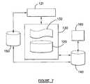
- FIG. 7is an overview of a violation processing system of the preferred embodiment
- FIG. 8is a block system module diagram of the embodiment of FIG. 8 ;
- FIG. 9is a flow chart illustrating operation of the embodiment of FIG. 7 ;
- FIG. 10is a plan view of an intersection having a traffic violation detecting system according to a further embodiment of the invention.
- FIG. 11is a view of a camera used in the embodiment of FIG. 10 ;
- FIG. 12is a view of part of the componentry of the camera of FIG. 11 ;
- FIG. 13is a view of an alternative arrangement that shown in FIG. 12 ;
- FIG. 14is a view of a fixed mirror system arrangement according to one embodiment
- FIG. 15is a view of the mirrors of FIG. 14 in plan
- FIG. 16is a view of a pixel array of a camera used in the preferred embodiment.
- FIG. 17is a view of the same array as in FIG. 16 except rotated 90°;
- FIG. 18is a view of a laser ranging system for detecting the presence of a vehicle according to this embodiment of the invention.
- FIG. 19is a block circuit diagram of site computer according to this embodiment of the invention.
- an intersection 10which is controlled by traffic signals 12 (only two of the signals shown for ease of illustration) is comprised of intersecting roadways A and B.
- the roadwayis marked with stop lines 14 and 16 (only those associated with the roadway A being shown) where vehicles will stop when a red light signal is displayed by the traffic signals 12 .
- the inventionrelates to a left side of the road driving environment such as that which exists in Australia.
- the stop lines 14 and 16are on the other side of the roadway in a right of the road driving environment such as that which exists in the United States of America. It should be understood that FIG. 1 is only showing a system for monitoring traffic flow in one direction along the roadway A.
- Additional systemscan be used to monitor the traffic flow in the opposite direction on the roadway A and also in the two direction of roadway B if desired.
- the system according to this embodiment of the inventionis mounted on a pole 18 and a pole 90 which may be existing poles or other road infrastructure, or specially installed poles.
- the pole 18mounts a wide angle camera 20 which can monitor the entire intersection of the roadways A and B as shown by the area 22 in FIG. 1 , and including at least one of the traffic signals 12 so that the image captured by the wide angle camera 20 includes the red light, amber light and green light associated with the traffic signals 12 .
- the purpose of detecting the light to the traffic signal 12is to determine a violation period such as when a red light signal is displayed as will be described in more detail hereinafter.
- the violation periodcan be from commencement of an amber light to the end of the red light phase of the traffic signals, or some other desired period defined by changes in the lights of the traffic signals.
- the traffic signals 12need not be monitored by the wide angle camera which also captures images of the region under surveillance. Depending on the size of the intersection or on other circumstances, a separate dedicated camera (not shown) which only captures images of the traffic signals 12 may be provided in order to allow the violation period to be determined.
- the pole 18also mounts narrow angle or lane cameras 30 each of which monitors or images one of the lanes of the roadway A.
- the roadway Ahas two lanes in each direction and therefore two lane cameras 30 are provided. If more than two lanes are provided additional lane cameras 30 are utilised.
- the pole 90mounts a further camera 91 which is directed perpendicular to the flow of traffic along the roadway A.
- the cameras 20 and 30are connected to a site computer 40 which is housed in a roadside cabinet or the like.
- the cameras 30therefore monitor part of the intersection which is monitored by the wide angle camera 20 and the parts monitored by the two cameras 30 are identified by the reference numerals 31 and 33 .
- the cameras 20 and 30are preferably off the shelf digital or video cameras which take images in low lighting conditions and have an auto iris to adjust for different lighting conditions. Typically the cameras have a pixel resolution of 768 by 576 and sustainable imaging rate of twenty five frames per second or better.
- Traffic movement through the intersectionis monitored by the narrow angle camera 91 mounted on pole 90 , perpendicular to the roadway A.
- This cameramonitors a section of the roadway identified by numeral 92 in FIG. 1 .
- the camera 91is also connected to the site computer 40 .
- the computer 40includes a processing section 50 which is powered by a mains power supply 52 .
- the processor 50includes memory buffer 54 which stores images captured by each of the cameras 20 and 30 and a processing section 56 which determines when a traffic violation has occurred and identifies the images stored in the memory buffer 54 and transfers those images to hard disc 58 so that only the images associated with the violation are stored on the hard disc 58 .
- the hard disc 58is connected to a wireless communication link 60 (or other communication link such as an Internet link) so that the data relating to the images stored on the hard disc can be transmitted to a central facility for further processing to provide a number of images which relate to the violation and also to identify the number-plate of the vehicle associated with the violation so that an appropriate penalty notice can be issued.
- a global positioning system (GPS) 93is connected to the buffer and stamps each image with an independently sourced date, time and location coordinates in order to identify the time and location of the event.
- the GPS systemobviously obtains this data from satellites, as is conventional, in order to provide a location reference and this, together with the time reference produced by the GPS system 93 , enables independently verified time and location data to be included to precisely identify the location of the event which is recorded by the system of the preferred embodiment of the invention.
- the processor 50is equipped with sufficient buffer memory 54 for temporary storage of a sufficient number of images taken by both the wide angle camera 20 and the lane cameras 30 so as to provide sufficient evidence to cover one or a number of simultaneous violations and to provide the image sequence(s) to prove the violation(s).
- the wide angle camera 20will capture images showing the violation, that is a vehicle moving through the intersection when the red light signal is displayed and the lane cameras 30 will take images of the vehicle in the lane concerned so that those images can be processed to determine the number plate of the vehicle concerned so the vehicle can be identified and the appropriate penalty notice issued.
- the processing section 56analyses the images taken by the camera 20 so that a change in the colour of the red light of the traffic signal 12 can be determined and therefore the commencement and end of the red light traffic phase of the signal 12 is determined.
- the system of the preferred embodimentalso includes a traffic movement detection section 94 which is also connected to processing system 56 .
- the detection section 94analyses the images taken by the camera 91 to identify movement of traffic through the intersection during the red light phase of the traffic signal. If traffic movement through one of the lanes of the roadway is determined during the period of the red light phase, the section 94 triggers a traffic violation to be captured by processing section 56 .
- the images which are associated with that violationare then transferred from the memory buffers 54 to the hard disc 58 so that a sequence of images captured by the wide angle camera 20 showing the vehicle moving through the intersection and also at least one image captured by one of the lane cameras 30 which show the vehicle in close up are also captured.
- Those imagesare transmitted via the wireless communication link 60 to a central facility where the images can be developed or printed to provide evidence of the violation and also the images are inspected so that the number-plate of the vehicle concerned can be determined so that the appropriate penalty notice can be issued.
- the image analysis equipmentmay be provided for detection or recognising a licence plate of a vehicle, so that if a recognised licence plate of a vehicle is seen in the image in the appropriate time zone indicative of the red light phase, a determination is made that a particular vehicle is present.
- the inventionenables relatively inexpensive cameras to be used and which can operate in effectively very low lux conditions, no supplementary flash illumination is required even at night. If lighting conditions are insufficient for operation of the cameras for any reason light intensifiers or infrared illuminators could be used in the system to enable images to be captured and processed to identify a violation.
- a further camera 91is used to determine movement of traffic through the intersection during the red light phase of the traffic lights.
- one of the other cameras 20 or 30could be used to perform this function.
- the camera 91is preferred because it is arranged perpendicular to the flow of traffic, and therefore, is able to more easily monitor movement of traffic because a movement will cross the path of the camera rather than move in the general direction of the field of view of the camera.
- processing of images to determine movement of a vehicle through the intersectionis easier to perform with the camera 91 rather than by use of the cameras 20 or 30 .
- a reference imageis created based on histogram pixel values over a number of frames.
- the reference imageis built up whilst traffic is moving, thereby minimising the chance of vehicles becoming part of the reference frame.
- the reference frameis continuously updated over time with new images captured by the camera 91 , adding to the body of data which is used to establish the reference image and earlier images being discarded.
- the reference imageis provided with a plurality of predefined trigger points and a violation is determined by comparing a captured image with the reference frame such as by simply subtracting the current image from the reference frame. If the comparison of the current frame with the reference frame determines something in the current frame at the predetermined trigger points, then an event is generated to show a violation has occurred.
- the way in which the reference frame is built upcan change depending on the time of day. For example, at night the reference frame can be built up slightly differently to take into account vehicle headlights.
- the image which is associated with a violationis determined by the computer 40 by the time reference which is established by the GPS system 93 .
- the GPS system 93enables a time reference to be created.
- the images which are captured by the camerasalso have that time reference stamped on them, as has been previously explained.
- the image which corresponds to that timecan be transferred from the buffers 54 to the hard disc 58 , together with a number of images on either side of that particular image, so that a set of images showing the violation can be retained.
- the images which are retainedare those from the wide angle camera 20 and also the narrow angle cameras 30 . If desired, the images which are captured by the camera 91 can also be retained.
- FIG. 4is a flow chart illustrating initial calibration or set up of the system of FIG. 1 .
- the system of FIG. 1is set up via a graphical user interface operating on a laptop that can be connected to the computer 40 .
- the softwarewill allow the operator to take test shots using the wide angle camera 20 .
- On the test image captured by the operatorthe operator will define the position of the red signal heads (that is a red light) on the signals 12 by drawing a box, and defining the position of each of the red, green and amber signal lights.
- the operatorwill also draw a line to define the position of the stop line 14 on the image and will draw a series of lines to define each of the lanes of the roadway that are to be monitored.
- the camera 91is also calibrated in the same manner as described above and shown in FIG. 4 .
- a test shotis taken by the camera 91 , and on the test image which is captured, the operator will define the position of the stop line 14 and also each of the lanes which can be seen in that image.
- the operatorwill also identify a number of reference locations in the image which define trigger points to enable an indication of movement of a vehicle in captured images by the camera 91 to be determined so that the speed of the vehicle moving past the stop line 14 can be estimated.
- FIG. 5is a flow chart explaining operation of the system of FIG. 1 .
- Each frame taken by the wide angle camerais examined by the processing software to identify the status of the traffic signal.
- the colour pixels in the area defined by the setup system to identify the position of each of the red, green and amber signal lightsare analysed and a determination will be made of the current phase.
- Each of the areas delineated by the setup software to represent the traffic laneswill be compared frame by frame. A determination will be made if movement is present during the red signal phase and if the movement continues past the stop line 14 .
- the lane in which the movement is detectedwill also be recorded.
- the images taken by the wide angle camera 20(both before the point of detection and after the point of detection) will be retained and transferred from the buffer 54 to the hard disc 58 .
- the images taken by the appropriate lane camera 30are also retained and stored in the same manner.
- the images of the wide angle camera and the lane camera pertaining to the one eventwill be linked by a suitable identification code and additional information including the GPS sourced time, date, location, lane and approximate vehicle speed will be appended to the event images as a total image and data set.
- the data setscan be encrypted and also digital signature and compression algorithms can be used to compress the data and the data can then be transmitted by the communication link 60 to processing centre where the images can be decrypted and viewed for adjudication, verification, tamper validation and traffic penalty notice issuance.
- the systempreferably retains at least two of the images prior to triggering of the event.
- first detection of the vehicle crossing the line 14 during the red light phase of the traffic signalsthe image associated with that actual event (ie., the image showing the vehicle crossing the line 14 ), and at least two images subsequent that event so that a number of images are provided, showing the camera approaching the line 14 , reaching the line 14 and then passing into the intersection during the red light phase of the traffic signals.
- the GPS systemstamps the images with the location, date and time of the event.
- the approximate speed of the vehicle, as the vehicle passes through the intersection 14is also recorded. This is done by analysis of the images from the camera 91 . The determination of the speed need not be as accurate as would be required if the violation being detected was actually a speed violation rather than a red traffic light violation. However, even with a red traffic light violation, some indication of the speed of the vehicle may be required in some jurisdictions.
- the speed of the vehicle in the embodiment of FIG. 1is therefore determined by tracking the vehicle movement from frame to frame in the images captured by the camera 91 , over a predefined distance on the road. Assuming that the frame rate is 50 half-fields per second, an estimation of the speed of the vehicle as it runs the red light can be made.
- the image captured by the camera 91may have predetermined location points identified in it which can be compared with the position of the vehicle in the images so that an indication of the distance the vehicle has moved from one frame to the next frame can be determined.
- FIG. 2shows the system used for detecting speed violations.
- a region of a roadway Cis monitored by wide angle camera 20 and each of the appropriate lane ways of the road C are monitored by lane cameras 30 .
- the cameras 20 and 30are connected to site computer 40 .
- the regions monitored by the cameras 20 and 30are shown by the reference numbers 81 insofar as the camera 20 is concerned and the reference numbers 82 and 83 insofar as the cameras 30 are concerned.
- Initial set up in this embodimentis the same as that described with reference to FIG. 4 except that obviously the traffic signals 12 are not identified and the regions which are identified are the regions of the roadway monitored by the camera 20 and the specific lanes monitored by the cameras 30 . Images are captured in the same way as described with reference to FIG. 1 and the determination for a speed event is made by an external speed measuring device such as Doppler radar or laser speed measuring device. The lane in which the vehicle is travelling is determined in the same manner as described with reference to FIGS. 1 and 3 to 5 .
- the speed measuring deviceWhen the speed measuring device detects a vehicle or vehicles exceeding the threshold speed which has been set by an operator, a number of images from both the wide angled camera and the lane cameras 30 (both before and after the speed event) are retained and stored together with information that include date, time, event location, direction of travel, and vehicle speed also lane information. This data is transmitted by the link 60 in the same manner as described above so, that the images can be processed to produce a penalty notice.
- imagesare continuously captured by the cameras 20 and 30 in both of the embodiments described above and are stored in temporary buffer memory 54 , it is not necessary to provide an intrusive vehicle detection system such as detectors in the roadway or to link the system to the traffic signals in order to provide a trigger to commence operation of the system to capture a violation. Rather, images are continuously captured and are processed so that, in the case of red light violation, the violation can be determined from processing, and those images associated with the violation are retained and transmitted for penalty note issuance, and in the case of a speed violation, when the speed detection equipment indicates a violation, images of the continuously captured images are then transferred to the hard disc 58 for transmission to the central facility.
- the time, date and location of the eventis stamped on the images which are captured by the GPS system 93 .
- FIG. 6is a flow diagram of a further embodiment of the invention in which an accident is detected and which enables images of the accident to be captured to provide evidence of the accident.
- a directional microphone 100is mounted on the pole 18 or in any other suitable location for monitoring ambient sound from the intersection.
- the microphone 100is connected to the processing section 56 , as is shown in FIG. 3 .
- the processing section 56is provided with sound wave patterns indicative of the noise of an accident, and these sound wave patterns are stored in memory to provide reference patterns for determining if an accident has occurred at the intersection.
- the microphone 100continuously monitors the ambient sound from the intersection and the sound wave pattern detected by the microphone 100 is processed and continuously compared with the sample sound patterns stored within the processing section 56 .
- the microphone 100detects a sound pattern consistent with one of the stored sound patterns within the processing section 56 , this is taken as an indication of an accident within the intersection and an event is triggered, as is shown in FIG. 6 .
- Thiscauses the wide angle image captured by the wide angle camera 20 to be transferred to the hard disc 58 . Also, at least two images prior to that image are also transferred to the hard disc 58 , and two images subsequent to that image are transferred to the hard disc 58 .
- the sound pattern indicative of a traffic accidentcauses the retention of images in the same manner as a red light violation or speed violation, as in the earlier embodiments. These images may be captured concurrently with or instead of speed violation images or red light violation images. Thus, the facts of the event are therefore captured and recorded, which can provide information as to the nature and cause of the accident in any further proceedings.
- the processor 50forms the functions of processing the images taken by the camera in order to determine the red light phase and also to determine whether a vehicle is present in the intersection during the red light phase, as well as processing ambient sound to determine whether an accident has occurred, and then identifying the relevant images for transfer to the hard disc 58 .
- a single processing section 56is provided to perform all of these functions
- the processor 50could include several separate processing sections, each of which performs only one or some of the functions referred to above.
- the processormay therefore effectively include a single board in which all processing is performed, or a number of separate processing boards which are suitably coupled together if necessary to perform of the above-mentioned functions.
- the images captured by the camerascan also be analysed to enable vehicles to be classified. That is, by image analysis, the type of vehicle, ie. car, truck, motorcycle, etc., can be determined to provide some statistics on the nature of the vehicles which are using that particular part of the roadway. Furthermore, the preferred embodiment of the invention may also be able to determine a particular traffic light sequence which may allow vehicles to travel through the intersection, such as turning arrows, flashing red or amber lights indicating that a vehicle should approach the intersection with caution but may cross the intersection during the period of the flashing lights, so that those traffic signals do not prompt a violation to be recorded.
- a particular traffic light sequencewhich may allow vehicles to travel through the intersection, such as turning arrows, flashing red or amber lights indicating that a vehicle should approach the intersection with caution but may cross the intersection during the period of the flashing lights, so that those traffic signals do not prompt a violation to be recorded.
- the inventionis also applicable to detecting traffic violations which relate to failure to pay at tollways or tollbooths associated with a roadway.
- vehiclescarry electronic devices which are automatically detected and recorded when the vehicle passes a toll station on the roadway.
- a single photograph of a vehicle passing the tollwayis captured to enable the vehicle to be identified if the electronic device is not detected.
- the camerasas arranged in a similar as described with reference to the earlier embodiments to capture a sequence of photographs continuously as in the earlier embodiments.
- the time of detectionis recorded via the GPS system as in the earlier embodiments, and the sequence of images associated with that violation are therefore retained as in the earlier embodiments, to provide evidence of the infringement and also to enable the vehicle to be identified.
- This embodimenthas particular advantages in tollbooth situations, because in some instances it is very difficult for a single photograph taken from a tollbooth station to properly identify a licence plate of the vehicle.
- the fact that the present embodimentenables a sequence of photographs to be taken, which include photographs of the actual violation, together with photographs prior to and following the violation, provides more images from which the vehicle number plate can be identified.
- the preferred embodiment of the inventionalso provides a method and system for processing violations which are captured by the systems described with reference to FIGS. 1 to 6 , and the tollway violations described above.
- the embodiment of FIGS. 7 to 9enables violations to be processed by a relevant department, such as a police department, information to be assembled for preparation of fines or court proceedings, and also for monitoring and review by authorised users of the system, such as police department, court officials, city officials and the like.
- the systemalso enables individuals who have been forwarded a violation notice to inspect the images associated with that violation should they so desire.
- FIGS. 7 to 9provides real time communications between all field systems of the type described with reference to FIGS. 1 to 6 , and one or more central databases 120 (see FIG. 7 ) and all users and managers concurrent access to data by different users.
- dataOnce data is stored within the system, the only thing that changes is its status, eg., the status of a particular set of data may be altered from “pre-verified” to “accepted”, at which point it becomes available for police authorisation.
- the systemmay be accessed by different classes of authenticated users (including for example, personnel associated with the operating system, client personnel such as police officers, court officials, verification operators and city managers, or the individual citizens who may wish to view evidence of their traffic fine via the Internet).
- the systemincludes a web server 121 which acts as the main entry point for all external requests for information and updates and allows browser-based, interactive access for authenticated users in any location. This allows a distributed infrastructure which can be accessed globally with full authenticated security.
- the database 120is contained within a violation processing engine 130 which also includes business logic, represented by reference 132 , which relates to the protocols and manner with which different clients may wish to deal with information concerning a violation in their particular jurisdiction. For example, a single database could be utilised for storing and processing violations captured in a number of different cities. Each of those cities may require a different protocol for forwarding fine notices, for prosecution purposes or otherwise.
- the violation processing enginetherefore enables each of the specific users to process data relating to their particular violations in a specific way applicable to them.
- a single database or set of databasescan be utilised without the need to specifically tailor a specific database for each individual user's requirements.
- the violation engine 120contains the broad range of business logic necessary to perform traffic camera office operations in respect of processing red light running, speeding and toll violation evidence. These operations include:
- An event server 140which is preferably in the form of a large scalable database server, is provided and onto which primary evidence (ie., the images and data captured by the system of FIGS. 1 to 6 ) is loaded.
- the event server 140received the data from the link 60 in FIG. 3 by way of Internet connection or in any other suitable manner.
- the event servermaintains the integrity of all primary evidence because, for example, any image modification (such as gamma correction) is only performed on duplicate images that have been received from the server for processing.
- a report server 150is connected to the event server and also to the web server 121 to enable memory intensive reporting requirements.
- An archiver 160is also provided which purely rechecks the status and age of all events stored on the event server, against the relevant client's agreed business rules, and uses this information to remove outdated data and images and archive them.
- FIG. 8is a systems module diagram of the system described with reference to FIG. 7 .
- the module of FIG. 8includes a module 200 for receiving data and images from the site computers 40 and, as previously described, this information may be transmitted by way of Internet connection or by any other suitable method.
- the module 200therefore receives information relating to a particular customer which may be a city authority, or the like.
- the datais received by an interface 201 which converts the data, if necessary, into a particular format which can be read and processed by the remainder of the system of FIG. 8 .
- the data from the various systemsis automatically regularly polled so that the violations images are received by the system of FIG. 8 .
- the images and dataare then supplied to the event server 140 from event interface 201 , data interface 202 , which in turn receives data transformed by module 204 .
- the event server 140includes an image server module 141 and a data server module 142 which are connected to the business process module 132 which contains the protocols relating to a particular customer to enable the information relating to a violation to be compiled and treated in accordance with the business rules of that particular customer.
- images and datamay be archived by the archiver 160 in accordance with the rules of a particular customer.
- Details relating to the owner of the vehicleare retransmitted back via module 156 and are transformed by module 165 back into a format which will be understood by the system of FIG. 8 and into the relevant format required by the specific user.
- the informationmay be then forwarded to a print server 161 for printing images of the event and to a notice module 162 which creates a notice for printing, such as a fine or the like, which is forwarded to the owner of the vehicle.
- the business module 132is also connected to a report generator module 163 which enables specific reports to be generated relating to the infringement activity detected by various systems within the user's infrastructure. Standard reports according to the requirements of a specific customer may then be generated by module 164 .
- Web interface 170enables authorised users and civilians to access the system so as to process violations or view a violation relevant to a particular citizen.
- the web interface 170enables a user to logon to the system via module 172 .
- the user's authentication code and logon detailswill therefore define the access the user has to the system of FIG. 8 .
- an authorised officerto determine whether a violation has occurred, such as a police officer, town clerk or other authorised personnel, logs on, that person will be able to access images relating to the jurisdiction for which that person has responsibility, and determine whether a violation has occurred from those images.
- the authorised personlogs on at step 171 and queries all events in that person's jurisdiction at step 172 .
- the eventsare then compiled and displayed on the user's screen at step 173 so that the user can determine whether a violation has occurred. If this is the case, the registration details of the vehicle are determined by accessing the authority 300 in the manner previously described. As explained hereinafter, requests for registration details may be batched for automatic look up at a later date. An event report, such as a summons, fine or the like, may then be generated and forwarded to the vehicle owner, as also previously described.
- the web interface 170also enables the authorised person to then go to the next event 174 and continue the process until all recorded events have been processed and verified.
- the images relating to a particular eventcan be inspected in turn to observe the sequence of images which relate to the event and also the details of the license plate of the vehicle concerned.
- Module 176enables an update of the system to show that fines have been paid or that no activity has occurred and that court proceedings should be instigated or any other activity which may be required by a particular customer.
- the business process module 132may also be connected to other authorities, collectively shown at 303 , which may need to interrogate the system to determine particular events applicable to them.
- all information stored in the event server 140may be accessed dynamically by any authenticated user according to the controls inherent in their authentication. For example, once violation images and violation data have been stored in the event server, they are available to any authenticating process officer for verification purposes. Once the operator has logged in and defined their verification request, the system displays images and data on their PC screen. Operators can click onto an image to enlarge if it is required. They may also request that a full image set (eg., all license plate images for a particular violation) be furnished if required. License plate details may be supplied to the event server by the field OCR systems, or may be entered or edited manually by the operator at this stage.
- Operatorsmay accept/reject evidence for a particular event or end it or mark it for review by a supervisor or another operator. Only when evidence meets the client's legal and business rules are violations accepted and further processed by the system.
- Verified violation events(containing the license plate number of the vehicle) are batched for automatic look-up at the authority 300 which automatically populates the registered owner information on the appropriate notice which is presented for authorisation so that all relevant information is available for review by the authorising officer.
- Authorised usersmay also have secure, dynamic, browser-based access to data held in the system (at their particular privilege level) for any computer with Internet access. They may login using their assigned user name and password—and additional security, eg. an USB token (which is inserted into the appropriate port of the computer), request immediate access to evidence for defined classes of verified violations/particular violation event, for immediate display on screen, accept or reject the violation with a single click, request image enlargement, request multiple image set images for each display image and scroll through these, authorise issue of the relevant letter notice and electronically sign if desired, request standard system reports by the module 164 .
- additional securityeg. an USB token (which is inserted into the appropriate port of the computer)
- request immediate access to evidence for defined classes of verified violations/particular violation eventfor immediate display on screen, accept or reject the violation with a single click, request image enlargement, request multiple image set images for each display image and scroll through these, authorise issue of the relevant letter notice and electronically sign if desired, request standard system reports by the module
- the systemgenerates a print file for printing and mailing as per the modules 160 and 162 which may be warning letters, fine notices, notices to appear or summonses. These documents may display relevant violation images if required, and are customised to meet the customer's legal requirements. All mailing details are automatically recorded by the system.
- Standard reportsinclude, for example, monthly reporting for:
- the databasemay be updated and maintained to show that various fines which have been issued have in fact been paid and therefore can be struck out of the system.
- the systemmay also generate official summonses for unpaid violations, as previously described, and also compile evidence packs for use in court, allow ad hoc viewing by police departments of past or current violations, and report on a monthly or random basis to relevant authorities.
- FIGS. 10 to 20An alternative embodiment to that shown in FIGS. 1 to 4 is shown in FIGS. 10 to 20 .
- intersectionwhich has a road C which may contain four lanes L 1 , L 2 , L 3 and L 4 . It should be noted that the intersection shown in FIG. 10 is applicable to right hand side motor systems such as that present in the USA.
- the systemincludes a wide angle camera 20 which is the same as the wide angle camera 20 previously described with reference to FIGS. 1 to 4 , for capturing images of the entire intersection.
- a domed camera assembly 199 having a fixed camera 210is provided for capturing narrow angle images of each of the lanes L 1 to L 4 in which a violation occurs.
- only one camerais provided to monitor a plurality of lanes.
- the intrusion of a vehicle into the intersection when a red light phase of a traffic control signal is presentmay be monitored by camera 91 which is the same as the camera 91 described with reference to FIGS. 1 to 4 .
- a further camera 211may be provided for capturing images of the face of a driver when a violation occurs.
- the camera 211may be identical to the camera 210 and operate in the same manner or, alternatively, a plurality of separate cameras for each of the lanes L 1 to L 4 can be provided for monitoring each of those lanes to capture images of a driver when a violation occurs in any one of those lanes.
- the cameras 20 , 210 , 91 and 211are mounted on poles in the same manner as the earlier embodiment.
- the ranging lasers 250 and 251are also mounted on poles so as to be located above the intersection, as will be described in more detail hereinafter.
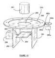
- FIG. 11shows the assembly 199 which has a housing 261 which includes a dome 262 .
- the housing 261is divided into a cool chamber 263 and a warm chamber 264 by a Peltier heat transfer layer 265 .
- the layer 265has an opening 266 and the camera 210 is provided with a lens 267 which locates in the warm chamber 262 and either projects through the opening 266 to be in optical communication with the camera 210 or is in optical communication with the camera 210 through the opening 266 .
- An infrared laser 268is mounted on the camera 210 for producing infrared illumination to illuminate a respective one of the lanes L 1 to L 4 with infrared illumination so that the illumination can reflect from the lane and vehicles, etc. in the lane back to the camera 210 so the camera can capture images of the lane and any vehicles in the lane.
- a moveable mirror 269is provided in the dome 262 for reflecting illumination from a respective one of the lanes L 1 to L 4 to the camera 210 so that images can be captured.
- the laser 268points at the mirror 269 so that the illumination produced by the laser is also directed to the lane to which the mirror 269 points so the laser 268 provides illumination to, that lane and reflected illumination from the lane is reflected by the mirror 269 to the camera 210 to capture the aforesaid images.
- the camera 210includes a CCD array 301 (see FIGS. 16 and 17 ) and the camera generates some heat during operation. As the temperature of the CCD array increases, there is a proportionate increase in the amount of noise in the image captured by the camera 210 .
- the Peltier layer 265which is located between the camera and lens, transfers heat away from the camera and, in particular, the CCD array of the camera to the warm chamber to thereby keep the environment of the lens 267 and the mirror 269 warm. This has the dual effect of creating clearer images on the CCD array and preventing fog from forming on the surfaces of the lens and mirror.
- FIG. 12shows one embodiment of the mechanism which comprises a first motor 271 and a second motor 272 .
- the motor 271drives screw threaded shafts 273 and 274 which are screw threaded to lugs 275 and 276 , which in turn are connected to mirror 269 .
- a fixed ball joint 278is connected to one of the other corners of the mirror 269 , and a spring 277 is provided for biasing the mirror by contacting the mirror at about the midpoint of the triangle formed by the corner at which the ball joint 278 is connected and the corners at which the shafts 273 and 274 are provided. The other end of the spring 277 is fixed.
- the spring 277biases the mirror 269 to its own home position.
- the mirroris preferably rectangular and the lugs 275 and 276 are connected to opposite corners of the mirror and the ball joint 278 to one of the other corners of the mirror.
- the motor 271produces tilt of the mirror 269 and the motor 272 produces pan of the mirror 269 .
- the motors 271 and 272are controlled by processor 56 when a violation is detected, so that the mirror is moved to aim at the lane L 1 to L 4 in which the violation occurs.
- That laneis illuminated with illumination from the laser 268 and reflected illumination is reflected by the mirror 269 to the camera 210 so images of the violation can be captured. If the image captured by the camera 210 needs to be enlarged, the lens 267 can zoom to the appropriate degree.
- the screw threaded shafts 273 and 274are rotated, allowing either or both corners of the mirror 269 to be raised or lowered. This will allow the mirror to be aimed in the appropriate location.
- a feedback system(not shown) may also be provided to let the processor 56 know the position of the mirror. The feedback system can also move the mirror back to a home position so as to minimise the amount of movement necessary to point at any one of the lanes so that the mirror can be quickly moved when a violation occurs, so the violation is captured by the camera 210 .
- the mechanism 270comprises a pan disc 280 which has a pair of supports 281 and 282 in which mirror 269 is journaled by axle 283 .
- the axle 283is rotated by motor 284 .
- the pan disc 280has a central hole 285 through which the camera lens 267 and camera 210 can view the mirror 269 .
- the disc 280is rotated by a motor and motor shaft 280 a which drives a gear 280 b which has gear teeth 280 c and mesh with gear teeth 280 d on the disc 280 .
- the disc 280could be driven by a belt which in turn is moved by a motor and pulley arrangement (not shown).
- the disc 280is rotatable to provide pan action and the motor 284 can tilt the mirror 269 to provide tilt action.
- the mechanism shown in FIG. 13provides a wider range of movement than that shown in FIG. 12 and therefore may be more suitable for particularly wide roads having a larger number of lanes.
- the tilt motor 284 and the rotation of the pan disc 280are controlled by the processor 56 when a violation is detected so the mirror points at the appropriate lane so the violation can be captured by the camera 210 .
- FIGS. 14 to 17show a still further embodiment in which a fixed mirror system formed by a plurality of mirrors 295 a to 295 d are used in place of the mirror 269 in the embodiments of FIGS. 12 and 13 .
- Thishas the advantage that it is not necessary to move the mirrors after installation and proper calibration.
- Each of the mirrors 295 a to 295 dare mounted on a respective panel 299 . As is apparent from FIG. 14 , each of the mirrors 295 a to 295 d are separate from one another. However, the mirrors 295 a to 295 d could be joined together to form an integral mirror in which the mirrors 295 a to 295 d are angled with respect to one another to reflect light in the appropriate direction to images the lanes L 1 to L 4 .
- Each of the panels 299is provided with a screw threaded shaft 297 and 298 in opposed corners, and one of the corners of the panels 299 between those opposed corners is fixed, as shown by reference 260 .
- the shafts 297 and 298are rotated by motors (not shown) to angle the mirrors so that each of the mirrors reflects the image from one of the respective lanes L 1 to L 4 onto a portion of the CCD array 301 of the camera 210 .
- the shaftsmay be provided with a handle 298 a so the respective shafts can be manually rotated to thereby adjust the alignment of the mirrors 295 a to 295 d .
- the CCD array 301is preferably 1280 ⁇ 1024 pixels.
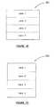
- FIG. 16shows a CCD array in one orientation
- FIG. 17shows the array rotated 90°
- the mirror segments 295 a to 295 dare arranged to reflect light from the lanes L 1 to L 4 onto the CCD array 301 , as identified by the references lane 1 to lane 4 in FIGS. 16 and 17 .
- all of the lanesare simultaneously imaged on the CCD array 301 with a different part of the CCD array imaging each of the lanes.
- each of the lanesare all imaged on the CCD array 301 , it is not necessary to move the segmented mirror arrangement 295 after it has been initially set up and calibrated, so as to properly reflect illumination from the lanes onto the CCD array 301 and therefore no movement of the camera 210 or the mirrors 295 a to 295 d is needed.
- the proper calibration and alignment of each of the mirrors 295 a to 295 dcan be performed when the camera is initially set up by manual adjustment so that the respective reflecting portions 299 properly point at their respective lanes so that those lanes are imaged on the CCD array 301 .
- the processor 56is programmed to know which parts of the array 301 relate to each of the lanes (or, in other words, which pixels of the array relate to each of the lanes) so that when a violation occurs in one of the lanes, the image created by those particular pixels is used to provide evidence of the violation.
- the image from the other pixelscan be blocked out to preserve privacy of any other vehicle which may be imaged by those pixels. In other words, only the image at the relevant part of the CCD array is extracted to provide evidence of the violation.
- the laser 268produces absolute infrared light (non-visible to the naked eye) to act as an external illuminator for the purpose of making a number plate and face of a driver of the vehicle brighter for capture by the dome camera 210 and by the camera 211 respectively (if the camera 211 is of the same configuration as the camera 210 ).
- the laserwill illuminate whatever the camera is viewing.
- the surface of a number plateis highly reflective to coherent laser light, the effect is a much higher contrast and more detailed image for identification in low light conditions.
- the laseris mounted on the camera and views the same location as the camera via the mirror 269 , the laser 268 could be mounted separately.
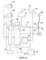
- this embodiment of the inventionuses an inductive sensor 200 (see FIG. 19 ) which is clamped to the electric wire 201 which provides electricity to the red light 202 of the traffic signal.
- an inductive sensor 200see FIG. 19
- the magnetic flux which is created by flow of electricity through the wire 201is sensed by the inductive sensor 200 and a signal is provided on line 203 to the processor 56 so that the processor 56 knows that the red light phase is active and present.
- the processor 56is provided with information showing when the red light phase of the traffic control signals is present, so that if a vehicle is present in the intersection and travelling along road C, the system knows that a violation has occurred.
- the camera 91can be used to provide an indication that the vehicle is in the intersection, as in the earlier embodiments.
- ranging lasers 250 and 251are provided for detecting the vehicle in the intersection. These lasers also have the advantage that they can easily be adjusted to also provide an indication of the speed of the vehicle so that not only can a red light violation be detected, but also a speed violation detected.
- the ranging lasers 250 and 251are arranged above a respective one of the lanes L 1 to L 4 .
- each of the lanes L 1 to L 4is provided with two of the ranging lasers 250 and 251 .
- the lasers 250 and 251are angled at predetermined angles marked ⁇ and ⁇ in FIG. 18 , which may be the same angle or different angles.
- the lasersare equipped with a ranging device, and hence are ranging lasers allowing them to measure the distance from the laser to any other point. These types of lasers are known and therefore will not be described in detail. However, suffice it to say that the lasers calibrate themselves to the fixed distance to the road surface and remember this distance.
- the processor 56measures the delay and a speed of the vehicle can therefore be determined. For example, if the beam from the laser 250 is broken at time T 1 as shown in FIG. 18 , and the beam from the laser 251 is broken at time T 2 , the time difference is obviously T 2 ⁇ T 1 . Since the angles ⁇ and ⁇ are known, as is the height of the lasers above the roadway, then the speed of the vehicle can be determined by the time difference measurement.
- the signalis output on line 309 (see FIG. 19 ) to processor 56 to thereby indicate that there is a vehicle in the intersection. If this coincides with the red light phase of the traffic control signal, as provided by the signal on line 203 , the image capture process is triggered to thereby identify those images which relate to the violation of all of the images captured by the camera. Thus, only the images relating to the violation are separated out of the continuous images captured by all of the cameras and are stored for providing evidence of the violation and also evidence of the vehicle and person who committed the violation.
- control signalsare output from the process 56 on line(s) 310 ( FIG. 19 ) to the mechanism 270 to control the mechanism 270 so that the camera via the moving mirror, points at the appropriate lane to capture the required images.
- all of the images captured by the camera 210will comprise images of the carriage way at which the camera was pointed, images showing movement of the camera and then images of the lane in which the violation is occurring and of the violation.
- the camera 210is focused at a part of the intersection so that, as soon as the violation is detected, there is sufficient time for the camera to move to the appropriate lane to capture images of the vehicle in the intersection whilst the red light phase is current to thereby provide evidence of the violation and evidence of the vehicle concerned.
- Those imagesare time and stamped recorded as in the previous embodiment, so that a particular set of images associated with the violation can be identified of all of the images captured by the camera 210 , and those images can then be transferred and transmitted to provide the required evidence in the same manner as in the previous embodiment.
- imagesare continuously captured and over time, are simply overwritten as the temporary storage becomes full.
- FIG. 19operates in exactly the same manner as FIG. 3 previously described, and the same reference numerals in FIG. 19 relate to the same components as described with reference to FIG. 3 .
- the method and system for processing violations described with reference to FIGS. 7 to 9is also used with the embodiment of FIGS. 10 to 19 .
- those images and the violation processoccurs as described with reference to FIGS. 7 to 9 .
- a set of images which are associated with a violationare identified and used as evidence.
- Those imagesmay typically comprise two images showing the vehicle prior to violation occurring, one image clearly showing the violation and two images after the violation to provide a sequence of images showing the occurrence of the violation.
- only a sequence of images showing the actual violationsuch as a sequence of images of a vehicle in the intersection during a red light phase can be provided.
- a series of photographssuch as six photographs, once again a complete picture of the violation is provided and more images are available to enable proper identification of the vehicle and also of the driver of the vehicle.
- processor 56which performs all of the processing functions previously described
- the processorcan be made up of a number of separate processors, each for performing various processing functions.
Landscapes
- Physics & Mathematics (AREA)
- General Physics & Mathematics (AREA)
- Traffic Control Systems (AREA)
Abstract
Description
- (a) The detection system is invariably unable to provide a trigger point that is sufficiently consistent to ensure that the positioning of vehicles at the time of imaging is identical. To compensate for this a wider angle lens is used with the consequence of reducing the available resolution for effective and efficient license plate recognition during subsequent evidence processing;
- (b) Conventional system's typically capture a single image of the vehicle licence plate. If this image is obscured or poorly focussed, it may be impossible to identify the vehicle. Likewise, with only one image of the driver, it may be difficult or impossible to provide an identifiable driver image where this is required;
- (c) High construction and maintenance costs (ie because of the costs of installing and maintaining in-ground sensors, underground cabling and connections to traffic signal controllers, flash units and in some instances where digital cameras are used, communications lines);
- (d) The use of flash illumination may be detrimental at night to oncoming traffic and has the potential to cause temporary driver blindness and consequent safety risks as well as preventing authorities from deploying systems covertly;
- (e) The requirement to install flash illumination units (often on a separate pole) also incurs additional supply, installation, maintenance and running costs and creates additional visual pollution;
- (f) Where digital cameras are used, systems either require the availability of high-speed communications lines to meet the demands of communicating high-resolution images, or else images and data must be collected manually;
- (g) Purpose built, high-resolution, digital traffic cameras are relatively expensive, adding to costs of traffic program installations and operation.
- (h) Traffic violation evidence collected by conventional systems includes time and data information provided by the camera computer clock which can be subject to error and therefore can prejudice the validity of evidence.
- (i) The requirement that violation processing software be installed and maintained in all computers in all processing offices and on all client computer systems in the various client locations incurs high program implementation and support costs.
- (j) With the exception of authorised processing personnel, users of violation evidence such as courts or police departments have been denied interactive access to information held by the central processing system and have only been able to request and view standard reports prepared for them by the relevant processing office.
- at least one camera for monitoring a region under surveillance;
- means for supplying independently sourced and verifiable time, date and location data to provide an indication of the time, date and location of a violation;
- a storing means for storing continuous images taken by the at least one camera;
- a non-intrusive violation detection means for detecting vehicle presence and movement through the region and for providing an indication of a violation; and
- processing means for identifying images stored in the storage means and which relate to a violation detected by the violation detection means so that images associated with a violation are identifiable and can be processed to provide evidence of the violation and also identify the vehicle associated with the violation.
- monitoring a region of a roadway with at least one camera;
- monitoring vehicle presence and movement through the region using a non-intrusive vehicle detection means
- storing images taken by the at least one camera;
- detecting a traffic violation in the region under surveillance;
- determining images stored by the storage means and which relate to the traffic violation so that images can be used as evidence of the violation and also to identify the vehicle associated with the violation; and
- stamping the images with time, date and location data which is independently sourced to provide the time, date and location of the violation.
- apparatus for determining when a red light phase of a traffic signal is present; and
- a device for determining when a vehicle has violated the red light phase of the traffic signal whilst the red light phase of the traffic signal is active.
- at least one camera for monitoring a region under surveillance and for viewing a traffic signal which includes traffic lights which change, to control flow of traffic through the region;
- temporary storage means for continuously storing images taken by the at least one camera;
- processing means for processing images taken by the at least one camera to determine changes in traffic lights of the traffic signal to determine the commencement and end of a traffic phase of the traffic signal to define a violation period; and
- processing means for determining that a violation has occurred from the images captured by the at least one camera and for identifying those images in the temporary storage means which are associated with the violation so that those images associated with the violation can be processed to provide evidence of the violation and to identify the vehicle associated with the violation.
- detecting a region of a roadway and a traffic signal by at least one camera;
- continuously capturing images of the region and signal and temporarily storing those images;
- detecting from the images changes in the traffic signal so that the commencement and end of a particular light traffic phase can be determined to define a violation period; and
- detecting a traffic violation in the violation period and identifying the stored images associated with the violation so that the stored images can be processed to provide evidence of the violation and identify the vehicle associated with the violation.
- at least one wide angle camera for monitoring a region under surveillance;
- a sound monitoring means to monitor and record ambient sound in the region under surveillance;
- temporary storage means for continuously storing images taken by the at least one camera and corresponding sound recordings; and
- processing means for determining that an intersection accident has occurred by analysing the sound recordings obtained by the sound monitoring means and identifying those sound recordings and images which are associated with the accident event to provide a visual record of the event.
- continuously communicating evidence of traffic violations and events to at least one server;
- providing real-time communications between all violation detection and recording systems and the server(s);
- providing a database containing information relating to violations detected by the violation detection and recording systems;
- dividing the database according to the different access requirements of different categories of authorised users with each user's level of access and functionality being automatically defined by their unique password and log-in process;
- allowing browser-based access to information held in the database or databases at a pre-defined level of authority for any authorised user using a computer with Internet connectivity;
- allowing interactive access to and operation of the violation processing system for individual users to perform evidence management tasks required by the authorities operating the system.
- continuously capturing and analysing ambient sound of a region under surveillance to detect a defined event;
- monitoring the region by at least one camera;
- continuously capturing images of the region and temporarily storing those images; and
- detecting a violation from the captured sound and identifying the stored images associated with the event so that the stored images can be processed to provide evidence of the event.
- a fixed camera for monitoring a plurality of lanes of a road and providing images of vehicles travelling in the lanes;
- a violation detecting system for detecting a traffic violation in any one of said plurality of lanes; and
- a reflecting system for selectively directing illumination from said any one of said plurality of lanes to said camera so that when a violation occurs in any one of said lanes, the reflecting system directs illumination from that lane to the camera so the camera can capture images of the violation occurring in that lane.
- an inductive sensor for sensing when a red light phase of a traffic signal is present; and
- a vehicle detector for detecting when a vehicle is present in a specified portion of the road.
- a temporary storage for continuously storing images taken by the fixed camera; and
- a processor for identifying those images in the temporary storage which are associated with the violation so that those images associated with the violation can be processed to provide evidence of the violation.
- a housing having a dome;
- a fixed camera mounted in the housing for monitoring a plurality of lanes of a road through the dome; and
- a reflecting system in the housing for selectively reflecting illumination from any one of the plurality of lanes to said fixed camera.
- reviewing evidence (images and data) for each alleged event to identify or verify violation events that have breached the relevant authority's traffic law/traffic code;
- making verified violations available for authorisation—and possible electronic signature—by jurisdiction officials (usually sworn police officers);
- ticketing (ie., printing and mailing authorised warning letters, traffic fines/notices, or summonses);
- tracking fine payments;
- producing reports to users of the system;
- producing evidence for the courts relating to specific traffic violation or events, including all event images (that is, the multiple set of images captured by the cameras and obtained when an event is determined, and which show the scene of the incident, the vehicle license plate and also the driver ID or face if required);
- producing data sheets relevant to the event; and
- creating an electronic audit trail (in place of sworn chain of custody statements by officers that are required with film cameras).
- the total number of violations recorded for the month;
- the number of letters/notices of violation issued;
- the number of letters/notices of violation not issued;
- break down by reason for non-issuance;
- the number of camera operating hours; and
- the number of violations recorded per camera operating hour.
Claims (22)
Priority Applications (2)
| Application Number | Priority Date | Filing Date | Title |
|---|---|---|---|
| US12/689,294US8134693B2 (en) | 2003-05-05 | 2010-01-19 | Traffic violation detection, recording and evidence processing system |
| US13/419,175US20120194357A1 (en) | 2003-05-05 | 2012-03-13 | Traffic violation detection, recording, and evidence processing systems and methods |
Applications Claiming Priority (4)
| Application Number | Priority Date | Filing Date | Title |
|---|---|---|---|
| US10/430,032US6970102B2 (en) | 2003-05-05 | 2003-05-05 | Traffic violation detection, recording and evidence processing system |
| US10/555,634US20060269104A1 (en) | 2003-05-05 | 2004-05-03 | Traffic violation detection, recording and evidence processing system |
| PCT/AU2004/000572WO2004100102A1 (en) | 2003-05-05 | 2004-05-03 | Traffic violation detection, recording and evidence processing system |
| US12/689,294US8134693B2 (en) | 2003-05-05 | 2010-01-19 | Traffic violation detection, recording and evidence processing system |
Related Parent Applications (2)
| Application Number | Title | Priority Date | Filing Date |
|---|---|---|---|
| PCT/AU2004/000572DivisionWO2004100102A1 (en) | 2003-05-05 | 2004-05-03 | Traffic violation detection, recording and evidence processing system |
| US11/555,634DivisionUS7283614B2 (en) | 2003-09-19 | 2006-11-01 | X-ray diagnosis apparatus and method for creating image data |
Related Child Applications (1)
| Application Number | Title | Priority Date | Filing Date |
|---|---|---|---|
| US13/419,175DivisionUS20120194357A1 (en) | 2003-05-05 | 2012-03-13 | Traffic violation detection, recording, and evidence processing systems and methods |
Publications (2)
| Publication Number | Publication Date |
|---|---|
| US20100128127A1 US20100128127A1 (en) | 2010-05-27 |
| US8134693B2true US8134693B2 (en) | 2012-03-13 |
Family
ID=33416164
Family Applications (4)
| Application Number | Title | Priority Date | Filing Date |
|---|---|---|---|
| US10/430,032Expired - LifetimeUS6970102B2 (en) | 2003-05-05 | 2003-05-05 | Traffic violation detection, recording and evidence processing system |
| US10/555,634AbandonedUS20060269104A1 (en) | 2003-05-05 | 2004-05-03 | Traffic violation detection, recording and evidence processing system |
| US12/689,294Expired - Fee RelatedUS8134693B2 (en) | 2003-05-05 | 2010-01-19 | Traffic violation detection, recording and evidence processing system |
| US13/419,175AbandonedUS20120194357A1 (en) | 2003-05-05 | 2012-03-13 | Traffic violation detection, recording, and evidence processing systems and methods |
Family Applications Before (2)
| Application Number | Title | Priority Date | Filing Date |
|---|---|---|---|
| US10/430,032Expired - LifetimeUS6970102B2 (en) | 2003-05-05 | 2003-05-05 | Traffic violation detection, recording and evidence processing system |
| US10/555,634AbandonedUS20060269104A1 (en) | 2003-05-05 | 2004-05-03 | Traffic violation detection, recording and evidence processing system |
Family Applications After (1)
| Application Number | Title | Priority Date | Filing Date |
|---|---|---|---|
| US13/419,175AbandonedUS20120194357A1 (en) | 2003-05-05 | 2012-03-13 | Traffic violation detection, recording, and evidence processing systems and methods |
Country Status (2)
| Country | Link |
|---|---|
| US (4) | US6970102B2 (en) |
| WO (1) | WO2004100102A1 (en) |
Cited By (10)
| Publication number | Priority date | Publication date | Assignee | Title |
|---|---|---|---|---|
| US20120136538A1 (en)* | 2010-11-22 | 2012-05-31 | GM Global Technology Operations LLC | Method for operating a motor vehicle and motor vehicle |
| US20130141253A1 (en)* | 2011-12-06 | 2013-06-06 | Sigma Space Corporation | Method for traffic monitoring and secure processing of trafic violations |
| US8600116B2 (en) | 2007-01-05 | 2013-12-03 | American Traffic Solutions, Inc. | Video speed detection system |
| AU2014202983A1 (en)* | 2013-09-11 | 2015-03-26 | Adox Pty Ltd | Parking Monitoring System |
| US9495601B2 (en) | 2013-12-09 | 2016-11-15 | Mirsani, LLC | Detecting and reporting improper activity involving a vehicle |
| US20200177872A1 (en)* | 2018-12-04 | 2020-06-04 | Ford Global Technologies, Llc | Vehicle sensor calibration |
| US11735042B1 (en)* | 2023-03-14 | 2023-08-22 | Pathfins C. Okezie | Traffic watch, monitor, and accident prevention device |
| US11869357B1 (en) | 2023-06-14 | 2024-01-09 | Pathfins C. Okezie | Method and apparatus for expanded traffic watch |
| US11967229B1 (en) | 2019-04-19 | 2024-04-23 | Board Of Trustees Of The University Of Alabama, For And On Behalf Of The University Of Alabama In Huntsville | Systems and methods for monitoring vehicular traffic |
| US12052381B1 (en) | 2024-03-14 | 2024-07-30 | Pathfins C. Okezie | Safety apparatus and method |
Families Citing this family (310)
| Publication number | Priority date | Publication date | Assignee | Title |
|---|---|---|---|---|
| US8352400B2 (en) | 1991-12-23 | 2013-01-08 | Hoffberg Steven M | Adaptive pattern recognition based controller apparatus and method and human-factored interface therefore |
| US10361802B1 (en) | 1999-02-01 | 2019-07-23 | Blanding Hovenweep, Llc | Adaptive pattern recognition based control system and method |
| US7904187B2 (en) | 1999-02-01 | 2011-03-08 | Hoffberg Steven M | Internet appliance system and method |
| US7880643B2 (en)* | 2001-12-19 | 2011-02-01 | Logobject Ag | Method and device for following objects, particularly for traffic monitoring |
| US20050264431A1 (en)* | 2002-04-09 | 2005-12-01 | Bachelder Aaron D | Forwarding system for long-range preemption and corridor clearance for emergency response |
| US7098806B2 (en)* | 2002-08-15 | 2006-08-29 | California Institute Of Technology | Traffic preemption system |
| US7158689B2 (en)* | 2002-11-25 | 2007-01-02 | Eastman Kodak Company | Correlating captured images and timed event data |
| FR2847755B1 (en)* | 2002-11-26 | 2005-04-22 | Cynove | IMAGE AUTHENTICATION METHODS |
| US7382277B2 (en) | 2003-02-12 | 2008-06-03 | Edward D. Ioli Trust | System for tracking suspicious vehicular activity |
| US6970102B2 (en)* | 2003-05-05 | 2005-11-29 | Transol Pty Ltd | Traffic violation detection, recording and evidence processing system |
| EP1623519A2 (en)* | 2003-05-07 | 2006-02-08 | Koninklijke Philips Electronics N.V. | Communication system |
| US7986339B2 (en)* | 2003-06-12 | 2011-07-26 | Redflex Traffic Systems Pty Ltd | Automated traffic violation monitoring and reporting system with combined video and still-image data |
| WO2005036494A2 (en)* | 2003-10-06 | 2005-04-21 | E-Views Safety Systems, Inc. | Detection and enforcement of failure-to-yield in an emergency vehicle preemption system |
| EP1709610B1 (en)* | 2003-10-14 | 2012-07-18 | Siemens Industry, Inc. | Method and system for collecting traffic data, monitoring traffic, and automated enforcement at a centralized station |
| JP4391839B2 (en)* | 2004-01-30 | 2009-12-24 | 富士通株式会社 | Shooting condition setting program, shooting condition setting method, and shooting condition setting apparatus |
| WO2005091243A1 (en)* | 2004-02-18 | 2005-09-29 | Gebert Ruediger Heinz | Method and system for verifying a traffic violation image |
| US7983835B2 (en)* | 2004-11-03 | 2011-07-19 | Lagassey Paul J | Modular intelligent transportation system |
| US20070040700A1 (en)* | 2004-03-24 | 2007-02-22 | Bachelder Aaron D | Cellular-based preemption system |
| US20060017562A1 (en)* | 2004-07-20 | 2006-01-26 | Bachelder Aaron D | Distributed, roadside-based real-time ID recognition system and method |
| US7265683B2 (en)* | 2004-08-18 | 2007-09-04 | California Institute Of Technology | Roadside-based communication system and method |
| US7348895B2 (en)* | 2004-11-03 | 2008-03-25 | Lagassey Paul J | Advanced automobile accident detection, data recordation and reporting system |
| EP1659551A1 (en)* | 2004-11-23 | 2006-05-24 | S.A.V.E. - Sistemi Avanzati di Elettronica di Domenico Ing. Monopoli & C. S.A.S. | Electronic registration system for detecting traffic violations |
| WO2006064172A1 (en)* | 2004-12-14 | 2006-06-22 | Roger Hal Kennedy | Integrated traffic management system |
| EP1854297B1 (en)* | 2005-02-23 | 2017-10-18 | Gatekeeper, Inc. | Entry control point device, system and method |
| DE212006000021U1 (en)* | 2005-03-03 | 2008-02-28 | Gebert, Rüdiger Heinz | System for the detection of speed measurements |
| US7710452B1 (en) | 2005-03-16 | 2010-05-04 | Eric Lindberg | Remote video monitoring of non-urban outdoor sites |
| US8370054B2 (en) | 2005-03-24 | 2013-02-05 | Google Inc. | User location driven identification of service vehicles |
| GB2425385B (en)* | 2005-04-18 | 2007-08-01 | Pips Technology Ltd | Vehicle speed monitoring system |
| US7920959B1 (en) | 2005-05-01 | 2011-04-05 | Christopher Reed Williams | Method and apparatus for estimating the velocity vector of multiple vehicles on non-level and curved roads using a single camera |
| US9230601B2 (en) | 2005-07-01 | 2016-01-05 | Invention Science Fund I, Llc | Media markup system for content alteration in derivative works |
| US9583141B2 (en) | 2005-07-01 | 2017-02-28 | Invention Science Fund I, Llc | Implementing audio substitution options in media works |
| US8126190B2 (en) | 2007-01-31 | 2012-02-28 | The Invention Science Fund I, Llc | Targeted obstrufication of an image |
| EP1932352A2 (en)* | 2005-09-27 | 2008-06-18 | Koninklijke Philips Electronics N.V. | Motion detection device |
| EP1960983B1 (en)* | 2005-12-15 | 2012-08-29 | International Business Machines Corporation | Method, system and program for auditing vehicle speed compliance to an upcoming speed limit |
| ITTO20060214A1 (en)* | 2006-03-22 | 2007-09-23 | Kria S R L | VEHICLE DETECTION SYSTEM |
| US7375652B2 (en)* | 2006-04-25 | 2008-05-20 | At&T Delaware Intellectual Property, Inc. | Systems and devices for assessing fines for traffic disturbances |
| US20070273552A1 (en)* | 2006-05-24 | 2007-11-29 | Bellsouth Intellectual Property Corporation | Control of traffic flow by sensing traffic states |
| US20070282519A1 (en)* | 2006-06-02 | 2007-12-06 | Ossama Emam | System and method for analyzing traffic disturbances reported by vehicles |
| US7646312B2 (en)* | 2006-08-11 | 2010-01-12 | Michael Rosen | Method and system for automated detection of mobile telephone usage by drivers of vehicles |
| US8131205B2 (en)* | 2008-05-01 | 2012-03-06 | Michael Rosen | Mobile phone detection and interruption system and method |
| US8384555B2 (en)* | 2006-08-11 | 2013-02-26 | Michael Rosen | Method and system for automated detection of mobile phone usage |
| US7786897B2 (en)* | 2007-01-23 | 2010-08-31 | Jai Pulnix, Inc. | High occupancy vehicle (HOV) lane enforcement |
| US20080180539A1 (en)* | 2007-01-31 | 2008-07-31 | Searete Llc, A Limited Liability Corporation | Image anonymization |
| US8055703B2 (en)* | 2007-03-05 | 2011-11-08 | Honeywell International Inc. | Method for verification via information processing |
| US9215512B2 (en) | 2007-04-27 | 2015-12-15 | Invention Science Fund I, Llc | Implementation of media content alteration |
| DE102007022373A1 (en)* | 2007-05-07 | 2008-11-13 | Robot Visual Systems Gmbh | Method for conclusively detecting the speed of a vehicle |
| US7595815B2 (en)* | 2007-05-08 | 2009-09-29 | Kd Secure, Llc | Apparatus, methods, and systems for intelligent security and safety |
| WO2009034465A1 (en)* | 2007-09-12 | 2009-03-19 | Digisensory Technologies Pty Ltd | Smart network camera system-on-a-chip |
| GB2452728A (en)* | 2007-09-12 | 2009-03-18 | David Speed | Intelligent traffic lights |
| US20090083133A1 (en)* | 2007-09-14 | 2009-03-26 | The Illinois State Toll Highway Authority | Method and system for electronic payment of missed tolls |
| US8013738B2 (en) | 2007-10-04 | 2011-09-06 | Kd Secure, Llc | Hierarchical storage manager (HSM) for intelligent storage of large volumes of data |
| WO2009045218A1 (en) | 2007-10-04 | 2009-04-09 | Donovan John J | A video surveillance, storage, and alerting system having network management, hierarchical data storage, video tip processing, and vehicle plate analysis |
| US9077863B2 (en)* | 2007-10-08 | 2015-07-07 | Nice Systems Ltd. | System and method for managing location based video services |
| ES2393459T3 (en)* | 2007-10-11 | 2012-12-21 | Jenoptik Robot Gmbh | Procedure for the detection and documentation of traffic violations at a traffic light |
| EP2075775B1 (en)* | 2007-12-27 | 2010-10-06 | JENOPTIK Robot GmbH | Method for documenting near simultaneous traffic violations |
| CN101470963A (en)* | 2007-12-26 | 2009-07-01 | 奥城同立科技开发(北京)有限公司 | Intelligent traffic light control system |
| CN101470955A (en)* | 2007-12-26 | 2009-07-01 | 奥城同立科技开发(北京)有限公司 | Integrated control system for road junction traffic |
| CN101472366A (en)* | 2007-12-26 | 2009-07-01 | 奥城同立科技开发(北京)有限公司 | Traffic light control system suitable for intersection control |
| US20090174572A1 (en)* | 2008-01-04 | 2009-07-09 | Smith Alexander E | Method and apparatus for an adaptive target vehicle notification system |
| US8031062B2 (en)* | 2008-01-04 | 2011-10-04 | Smith Alexander E | Method and apparatus to improve vehicle situational awareness at intersections |
| US8229168B2 (en)* | 2008-02-20 | 2012-07-24 | International Business Machines Corporation | Fast license plate verifier |
| US20090309974A1 (en)* | 2008-05-22 | 2009-12-17 | Shreekant Agrawal | Electronic Surveillance Network System |
| CN101620782A (en)* | 2008-06-30 | 2010-01-06 | 深圳富泰宏精密工业有限公司 | Regulation-violating behaviour evidence-obtaining system and method therefor |
| US8233662B2 (en)* | 2008-07-31 | 2012-07-31 | General Electric Company | Method and system for detecting signal color from a moving video platform |
| JP2010086265A (en)* | 2008-09-30 | 2010-04-15 | Fujitsu Ltd | Receiver, data display method, and movement support system |
| DE102008037463A1 (en)* | 2008-10-16 | 2010-04-22 | Cichon, Dieter, Dr.-Ing. | delineators |
| CN102224470B (en)* | 2008-11-24 | 2015-11-25 | Abb研究有限公司 | For providing the system and method for control and automation services |
| US20100149334A1 (en)* | 2008-12-17 | 2010-06-17 | Jon Wirsz | Fixed and mobile video traffic enforcement |
| CA2747337C (en)* | 2008-12-17 | 2017-09-26 | Thomas D. Winkler | Multiple object speed tracking system |
| AT10662U3 (en)* | 2009-03-05 | 2010-06-15 | Ct Comm Systems Gmbh | METHOD AND DEVICE FOR MONITORING A CROSSROYED SIGNALING SYSTEM |
| US7801512B1 (en)* | 2009-03-05 | 2010-09-21 | Makor Issues And Rights Ltd. | Traffic speed enforcement based on wireless phone network |
| US20100245125A1 (en)* | 2009-03-30 | 2010-09-30 | Lasercraft, Inc. | Systems and Methods For Surveillance and Traffic Monitoring (Claim Set I) |
| US20100245568A1 (en)* | 2009-03-30 | 2010-09-30 | Lasercraft, Inc. | Systems and Methods for Surveillance and Traffic Monitoring (Claim Set II) |
| US8310377B2 (en)* | 2009-08-24 | 2012-11-13 | Optotraffic, Llc | Mobile automated system for traffic monitoring |
| US20110161090A1 (en)* | 2009-08-26 | 2011-06-30 | Tilton Scott K | Automated ticket processing system and method |
| US8935095B2 (en)* | 2009-09-16 | 2015-01-13 | Utc Fire & Security Americas Corporation, Inc. | Safety system and device and methods of operating |
| US8493234B2 (en)* | 2009-12-07 | 2013-07-23 | At&T Mobility Ii Llc | Devices, systems and methods for detecting a traffic infraction |
| JP5462609B2 (en)* | 2009-12-09 | 2014-04-02 | 富士重工業株式会社 | Stop line recognition device |
| DE102009060499A1 (en)* | 2009-12-22 | 2011-06-30 | JENOPTIK Robot GmbH, 40789 | Method and arrangement for detecting traffic violations in a traffic light area |
| IL202880A (en)* | 2009-12-22 | 2011-03-31 | Sharon Ben Bassat | Method and system for traffic control by traffic lights |
| US9466212B1 (en)* | 2010-01-05 | 2016-10-11 | Sirius Xm Radio Inc. | System and method for improved updating and annunciation of traffic enforcement camera information in a vehicle using a broadcast content delivery service |
| US9001212B2 (en)* | 2010-03-11 | 2015-04-07 | Flir Systems, Inc. | Infrared transmissive dome systems and methods |
| US8905311B2 (en)* | 2010-03-11 | 2014-12-09 | Flir Systems, Inc. | Infrared camera with infrared-transmissive dome systems and methods |
| CN102201165A (en)* | 2010-03-25 | 2011-09-28 | 北京汉王智通科技有限公司 | Monitoring system of vehicle traffic violation at crossing and method thereof |
| US10643467B2 (en) | 2010-03-28 | 2020-05-05 | Roadmetric Ltd. | System and method for detecting and recording traffic law violation events |
| CA2794728A1 (en) | 2010-06-16 | 2011-12-22 | Ndi Technologies, Inc. | Usb video interface for alpr cameras and associated method |
| DE102010031056A1 (en)* | 2010-07-07 | 2012-01-12 | Robert Bosch Gmbh | Method for calibrating a measuring system and a measuring station for vehicle measurement |
| US8386156B2 (en)* | 2010-08-02 | 2013-02-26 | Siemens Industry, Inc. | System and method for lane-specific vehicle detection and control |
| CN101923780A (en)* | 2010-08-04 | 2010-12-22 | 深圳市中盟科技股份有限公司 | Traffic electronic police snapping control device and method |
| US9280895B2 (en)* | 2010-08-21 | 2016-03-08 | American Traffic Solutions, Inc. | System and method for detecting traffic violations on restricted roadways |
| TWI424382B (en)* | 2010-08-23 | 2014-01-21 | Univ Kun Shan | Method of recording real-time traffic signal |
| US8586955B2 (en)* | 2010-09-22 | 2013-11-19 | Ko Khee Tay | Apparatus and method for attenuating high energy radiation based on detected vehicle type |
| US9064406B1 (en)* | 2010-09-28 | 2015-06-23 | The Boeing Company | Portable and persistent vehicle surveillance system |
| CN101958056B (en)* | 2010-11-02 | 2012-11-14 | 江苏万新光学有限公司 | Emergency anti-collision prewarning system when driver runs red light |
| US20120148092A1 (en)* | 2010-12-09 | 2012-06-14 | Gorilla Technology Inc. | Automatic traffic violation detection system and method of the same |
| US8957535B2 (en) | 2011-01-17 | 2015-02-17 | Vestas Wind Systems A/S | Fault tolerant wind turbine converter |
| CN102136191B (en)* | 2011-01-27 | 2014-03-19 | 武汉经纬视通科技有限公司 | Multi-scene full-function all-in-one machine capable of capturing and monitoring |
| ES2427163T3 (en)* | 2011-03-22 | 2013-10-29 | Kapsch Trafficcom Ag | Procedure to validate a toll transaction |
| US8620032B2 (en)* | 2011-05-10 | 2013-12-31 | GM Global Technology Operations LLC | System and method for traffic signal detection |
| CN102254429B (en)* | 2011-05-13 | 2013-07-10 | 东南大学 | Video identification-based detection method of detection device of violation vehicles |
| US10451727B2 (en)* | 2011-05-13 | 2019-10-22 | Amirahmad Sepehri | Method and system for detecting moving vehicle speed through athird generation photo radar |
| US9019380B2 (en) | 2011-06-03 | 2015-04-28 | United Parcel Service Of America, Inc. | Detection of traffic violations |
| JP2013012836A (en)* | 2011-06-28 | 2013-01-17 | Nifco Inc | Data recording control device and data recording device |
| DE102011052218A1 (en)* | 2011-07-27 | 2013-01-31 | Jenoptik Robot Gmbh | Trailer for traffic monitoring |
| US9741249B2 (en)* | 2011-08-16 | 2017-08-22 | Conduent Business Services, Llc | Automated processing method for bus crossing enforcement |
| US20160232415A1 (en)* | 2011-08-16 | 2016-08-11 | Israel L'Heureux | Detection detection of cell phone or mobile device use in motor vehicle |
| US9137498B1 (en)* | 2011-08-16 | 2015-09-15 | Israel L'Heureux | Detection of mobile computing device use in motor vehicle |
| CN102956112A (en)* | 2011-08-25 | 2013-03-06 | 深圳富泰宏精密工业有限公司 | Traffic management device |
| CN102956115A (en)* | 2011-08-31 | 2013-03-06 | 深圳富泰宏精密工业有限公司 | Traffic management device |
| US8942913B2 (en)* | 2011-09-20 | 2015-01-27 | Infosys Limited | System and method for on-road traffic density analytics using video stream mining and statistical techniques |
| US20130073347A1 (en)* | 2011-09-21 | 2013-03-21 | Albert Bogaard | Vehicular citation management method and system |
| WO2013045714A1 (en)* | 2011-09-26 | 2013-04-04 | Unitronics Comunicaciones, S.A. | Traffic control device |
| US8953044B2 (en)* | 2011-10-05 | 2015-02-10 | Xerox Corporation | Multi-resolution video analysis and key feature preserving video reduction strategy for (real-time) vehicle tracking and speed enforcement systems |
| US20130093895A1 (en)* | 2011-10-17 | 2013-04-18 | Samuel David Palmer | System for collision prediction and traffic violation detection |
| CN103108117B (en)* | 2011-11-15 | 2017-02-15 | 上海宝康电子控制工程有限公司 | System and method for achieving synchronous fill-in light among intelligent video cameras in electronic police system |
| GB2493037B (en)* | 2011-11-24 | 2013-08-07 | Chersoft Ltd | Communicating electronic map data |
| JP5867153B2 (en)* | 2012-02-22 | 2016-02-24 | 富士通株式会社 | Traveling lane detection device, traveling lane detection method, and program |
| US8731245B2 (en)* | 2012-03-07 | 2014-05-20 | Xerox Corporation | Multiple view transportation imaging systems |
| CN103310642A (en)* | 2012-03-16 | 2013-09-18 | 捷达世软件(深圳)有限公司 | Road condition early warning system and road condition early warning method |
| TWI493478B (en)* | 2012-03-21 | 2015-07-21 | Altek Corp | License plate image-pickup device and image exposure adjustment method thereof |
| US20130253809A1 (en)* | 2012-03-26 | 2013-09-26 | International Business Machines Corporation | Collaborative near-miss accident reporting |
| WO2014007762A1 (en)* | 2012-07-04 | 2014-01-09 | Tan Seow Loong | A method and system for automated monitoring of traffic |
| EP2733677A1 (en)* | 2012-11-19 | 2014-05-21 | Kapsch TrafficCom AB | Device for tolling or telematics systems |
| US12211092B2 (en) | 2012-11-30 | 2025-01-28 | Bwi Acquisition, Inc. | Vehicle imaging and inspection system |
| US11756110B2 (en)* | 2012-11-30 | 2023-09-12 | Bwi Acquisition, Llc | Inspection and identification system and method |
| US12148024B2 (en) | 2012-11-30 | 2024-11-19 | Bwi Acquisition, Inc. | Computerized exchange network |
| US9524269B1 (en)* | 2012-12-19 | 2016-12-20 | Allstate Insurance Company | Driving event data analysis |
| US9535878B1 (en) | 2012-12-19 | 2017-01-03 | Allstate Insurance Company | Driving event data analysis |
| US9141995B1 (en) | 2012-12-19 | 2015-09-22 | Allstate Insurance Company | Driving trip and pattern analysis |
| US9141582B1 (en) | 2012-12-19 | 2015-09-22 | Allstate Insurance Company | Driving trip and pattern analysis |
| DE102012112754A1 (en)* | 2012-12-20 | 2014-06-26 | Jenoptik Robot Gmbh | Method and arrangement for detecting traffic violations in a traffic light area by tail measurement with a radar device |
| CN103020613A (en)* | 2013-01-07 | 2013-04-03 | 信帧电子技术(北京)有限公司 | Method and device for identifying signal lamps on basis of videos |
| CN103093245B (en)* | 2013-01-21 | 2016-01-20 | 信帧电子技术(北京)有限公司 | The method of marker lamp in video image |
| CN103150899B (en)* | 2013-02-01 | 2016-06-15 | 北京北智天成科技发展有限公司 | The monitoring method of Traffic Information, Apparatus and system |
| DE102013102683A1 (en)* | 2013-03-15 | 2014-09-18 | Jenoptik Robot Gmbh | Method for detecting traffic violations in a traffic light area by tailing with a radar device |
| US20140307087A1 (en)* | 2013-04-10 | 2014-10-16 | Xerox Corporation | Methods and systems for preventing traffic accidents |
| WO2014172708A1 (en) | 2013-04-19 | 2014-10-23 | Polaris Sensor Technologies, Inc. | Pedestrian right of way monitoring and reporting system and method |
| CN203305937U (en)* | 2013-04-25 | 2013-11-27 | 毛玉平 | Automobile intelligent monitoring evidence obtaining due punishment system |
| CN103236181B (en)* | 2013-05-10 | 2015-07-22 | 西安电子科技大学 | Traffic signal lamp state monitoring system and method based on machine vision |
| CA2914345A1 (en)* | 2013-06-06 | 2014-12-11 | Kustom Signals, Inc. | Traffic enforcement system with time tracking and integrated video capture |
| WO2015022567A1 (en)* | 2013-08-14 | 2015-02-19 | AGHAJANZADEH, Naser | Assistance system for automated, intelligent management of traffic regulations |
| TW201510946A (en)* | 2013-09-13 | 2015-03-16 | Yomore Technology Co Ltd | Addressable monitoring system |
| US9315192B1 (en)* | 2013-09-30 | 2016-04-19 | Google Inc. | Methods and systems for pedestrian avoidance using LIDAR |
| EP2858057A1 (en)* | 2013-10-03 | 2015-04-08 | Kapsch TrafficCom AB | System for traffic behaviour surveillance |
| US9558408B2 (en)* | 2013-10-15 | 2017-01-31 | Ford Global Technologies, Llc | Traffic signal prediction |
| US9892567B2 (en) | 2013-10-18 | 2018-02-13 | State Farm Mutual Automobile Insurance Company | Vehicle sensor collection of other vehicle information |
| US9262787B2 (en) | 2013-10-18 | 2016-02-16 | State Farm Mutual Automobile Insurance Company | Assessing risk using vehicle environment information |
| US9361650B2 (en) | 2013-10-18 | 2016-06-07 | State Farm Mutual Automobile Insurance Company | Synchronization of vehicle sensor information |
| US9530310B2 (en)* | 2013-11-01 | 2016-12-27 | Xerox Corporation | Method and system for detecting and tracking a vehicle of interest utilizing a network of traffic image-capturing units |
| WO2015106320A1 (en)* | 2014-01-16 | 2015-07-23 | Bartco Traffic Equipment Pty Ltd | System and method for event reconstruction |
| US9842266B2 (en) | 2014-04-04 | 2017-12-12 | Conduent Business Services, Llc | Method for detecting driver cell phone usage from side-view images |
| US9721173B2 (en)* | 2014-04-04 | 2017-08-01 | Conduent Business Services, Llc | Machine learning approach for detecting mobile phone usage by a driver |
| US9275286B2 (en) | 2014-05-15 | 2016-03-01 | Xerox Corporation | Short-time stopping detection from red light camera videos |
| US9685079B2 (en)* | 2014-05-15 | 2017-06-20 | Conduent Business Services, Llc | Short-time stopping detection from red light camera evidentiary photos |
| CN103956055B (en)* | 2014-05-15 | 2016-06-08 | 山西中创伟业科技有限公司 | A kind of method for snap control captured for vehicle image |
| US10185999B1 (en) | 2014-05-20 | 2019-01-22 | State Farm Mutual Automobile Insurance Company | Autonomous feature use monitoring and telematics |
| US10599155B1 (en) | 2014-05-20 | 2020-03-24 | State Farm Mutual Automobile Insurance Company | Autonomous vehicle operation feature monitoring and evaluation of effectiveness |
| US10373259B1 (en) | 2014-05-20 | 2019-08-06 | State Farm Mutual Automobile Insurance Company | Fully autonomous vehicle insurance pricing |
| US10319039B1 (en) | 2014-05-20 | 2019-06-11 | State Farm Mutual Automobile Insurance Company | Accident fault determination for autonomous vehicles |
| US9972054B1 (en) | 2014-05-20 | 2018-05-15 | State Farm Mutual Automobile Insurance Company | Accident fault determination for autonomous vehicles |
| US11669090B2 (en) | 2014-05-20 | 2023-06-06 | State Farm Mutual Automobile Insurance Company | Autonomous vehicle operation feature monitoring and evaluation of effectiveness |
| US20210133871A1 (en) | 2014-05-20 | 2021-05-06 | State Farm Mutual Automobile Insurance Company | Autonomous vehicle operation feature usage recommendations |
| US10733471B1 (en) | 2014-06-27 | 2020-08-04 | Blinker, Inc. | Method and apparatus for receiving recall information from an image |
| US9779318B1 (en) | 2014-06-27 | 2017-10-03 | Blinker, Inc. | Method and apparatus for verifying vehicle ownership from an image |
| US9892337B1 (en) | 2014-06-27 | 2018-02-13 | Blinker, Inc. | Method and apparatus for receiving a refinancing offer from an image |
| US10572758B1 (en) | 2014-06-27 | 2020-02-25 | Blinker, Inc. | Method and apparatus for receiving a financing offer from an image |
| US9563814B1 (en) | 2014-06-27 | 2017-02-07 | Blinker, Inc. | Method and apparatus for recovering a vehicle identification number from an image |
| US9558419B1 (en) | 2014-06-27 | 2017-01-31 | Blinker, Inc. | Method and apparatus for receiving a location of a vehicle service center from an image |
| US10540564B2 (en) | 2014-06-27 | 2020-01-21 | Blinker, Inc. | Method and apparatus for identifying vehicle information from an image |
| US9607236B1 (en) | 2014-06-27 | 2017-03-28 | Blinker, Inc. | Method and apparatus for providing loan verification from an image |
| US9594971B1 (en) | 2014-06-27 | 2017-03-14 | Blinker, Inc. | Method and apparatus for receiving listings of similar vehicles from an image |
| US9818154B1 (en) | 2014-06-27 | 2017-11-14 | Blinker, Inc. | System and method for electronic processing of vehicle transactions based on image detection of vehicle license plate |
| US10515285B2 (en) | 2014-06-27 | 2019-12-24 | Blinker, Inc. | Method and apparatus for blocking information from an image |
| US9600733B1 (en) | 2014-06-27 | 2017-03-21 | Blinker, Inc. | Method and apparatus for receiving car parts data from an image |
| US9589201B1 (en) | 2014-06-27 | 2017-03-07 | Blinker, Inc. | Method and apparatus for recovering a vehicle value from an image |
| US9754171B1 (en) | 2014-06-27 | 2017-09-05 | Blinker, Inc. | Method and apparatus for receiving vehicle information from an image and posting the vehicle information to a website |
| US10867327B1 (en) | 2014-06-27 | 2020-12-15 | Blinker, Inc. | System and method for electronic processing of vehicle transactions based on image detection of vehicle license plate |
| US10579892B1 (en) | 2014-06-27 | 2020-03-03 | Blinker, Inc. | Method and apparatus for recovering license plate information from an image |
| US9773184B1 (en) | 2014-06-27 | 2017-09-26 | Blinker, Inc. | Method and apparatus for receiving a broadcast radio service offer from an image |
| US9760776B1 (en) | 2014-06-27 | 2017-09-12 | Blinker, Inc. | Method and apparatus for obtaining a vehicle history report from an image |
| US9589202B1 (en) | 2014-06-27 | 2017-03-07 | Blinker, Inc. | Method and apparatus for receiving an insurance quote from an image |
| US10387962B1 (en) | 2014-07-21 | 2019-08-20 | State Farm Mutual Automobile Insurance Company | Methods of reconstructing an accident scene using telematics data |
| CN105336170B (en)* | 2014-08-08 | 2017-09-19 | 杭州海康威视系统技术有限公司 | Traffic violation supervising method and its device |
| KR20160038944A (en)* | 2014-09-30 | 2016-04-08 | 주식회사 디아이랩 | traffic monitoring system |
| US9759812B2 (en)* | 2014-10-02 | 2017-09-12 | Trimble Inc. | System and methods for intersection positioning |
| US10664707B2 (en)* | 2014-10-06 | 2020-05-26 | Marc R. Hannah | Managed access system for traffic flow optimization |
| US10157423B1 (en) | 2014-11-13 | 2018-12-18 | State Farm Mutual Automobile Insurance Company | Autonomous vehicle operating style and mode monitoring |
| WO2016093553A1 (en)* | 2014-12-12 | 2016-06-16 | 서울대학교 산학협력단 | System for collecting event data, method for collecting event data, service server for collecting event data, and camera |
| CN104537844B (en)* | 2015-01-26 | 2016-08-24 | 山东领信信息科技股份有限公司 | Vehicle License Plate Recognition System for peccancy detection |
| JP6193912B2 (en)* | 2015-04-24 | 2017-09-06 | 株式会社パイ・アール | Drive recorder |
| US10726863B2 (en) | 2015-04-27 | 2020-07-28 | Otocon Inc. | System and method for locating mobile noise source |
| TWI660160B (en)* | 2015-04-27 | 2019-05-21 | 維呈顧問股份有限公司 | Detecting system and method of movable noise source |
| CN104954738A (en)* | 2015-04-30 | 2015-09-30 | 广州视声光电有限公司 | Mobile detecting method and mobile detecting device |
| CN104867331B (en)* | 2015-05-06 | 2017-09-12 | 南京慧尔视智能科技有限公司 | Traffic incidents detection method and device based on microwave |
| KR102375411B1 (en) | 2015-05-11 | 2022-03-18 | 삼성전자주식회사 | Method and apparatus for providing around view of vehicle |
| US9904785B2 (en) | 2015-06-02 | 2018-02-27 | Rockwell Automation Technologies, Inc. | Active response security system for industrial control infrastructure |
| US9817391B2 (en) | 2015-06-02 | 2017-11-14 | Rockwell Automation Technologies, Inc. | Security system for industrial control infrastructure |
| US10042354B2 (en)* | 2015-06-02 | 2018-08-07 | Rockwell Automation Technologies, Inc. | Security system for industrial control infrastructure using dynamic signatures |
| US9898607B2 (en) | 2015-06-02 | 2018-02-20 | Rockwell Automation Technologies, Inc. | Rapid configuration security system for industrial control infrastructure |
| CN104966399B (en)* | 2015-06-03 | 2018-03-23 | 武汉万集信息技术有限公司 | A kind of vehicle-speed detecting device and method |
| US10055656B2 (en)* | 2015-06-05 | 2018-08-21 | Nissan Motor Co., Ltd. | Traffic signal detection device and traffic signal detection method |
| GB201510032D0 (en)* | 2015-06-09 | 2015-07-22 | Kp Acoustics Ltd | Integrated sensor system |
| KR101875833B1 (en)* | 2015-06-12 | 2018-07-06 | 주식회사 가치소프트 | Camera module and apparatus for processing product using the camera module |
| CN104994289B (en)* | 2015-06-30 | 2017-11-24 | 广东欧珀移动通信有限公司 | A kind of big visual angle camera starts method and system, camera terminal |
| US9805601B1 (en) | 2015-08-28 | 2017-10-31 | State Farm Mutual Automobile Insurance Company | Vehicular traffic alerts for avoidance of abnormal traffic conditions |
| CN105096606A (en)* | 2015-08-31 | 2015-11-25 | 成都众孚理想科技有限公司 | Automobile whistling and red light running snapshot system |
| WO2017123665A1 (en)* | 2016-01-11 | 2017-07-20 | Netradyne Inc. | Driver behavior monitoring |
| US10460600B2 (en) | 2016-01-11 | 2019-10-29 | NetraDyne, Inc. | Driver behavior monitoring |
| EP3193319A1 (en)* | 2016-01-13 | 2017-07-19 | Ekin, Akif | Smart recording, control and warning system for crossroad traffic |
| KR101895011B1 (en)* | 2016-01-14 | 2018-09-05 | (주)삼성정보통신 | System for checking traffic violation with detecting traffic road line |
| US10493936B1 (en) | 2016-01-22 | 2019-12-03 | State Farm Mutual Automobile Insurance Company | Detecting and responding to autonomous vehicle collisions |
| US10395332B1 (en) | 2016-01-22 | 2019-08-27 | State Farm Mutual Automobile Insurance Company | Coordinated autonomous vehicle automatic area scanning |
| US9940834B1 (en) | 2016-01-22 | 2018-04-10 | State Farm Mutual Automobile Insurance Company | Autonomous vehicle application |
| US10324463B1 (en) | 2016-01-22 | 2019-06-18 | State Farm Mutual Automobile Insurance Company | Autonomous vehicle operation adjustment based upon route |
| US11441916B1 (en) | 2016-01-22 | 2022-09-13 | State Farm Mutual Automobile Insurance Company | Autonomous vehicle trip routing |
| US10134278B1 (en) | 2016-01-22 | 2018-11-20 | State Farm Mutual Automobile Insurance Company | Autonomous vehicle application |
| US11242051B1 (en) | 2016-01-22 | 2022-02-08 | State Farm Mutual Automobile Insurance Company | Autonomous vehicle action communications |
| US11719545B2 (en) | 2016-01-22 | 2023-08-08 | Hyundai Motor Company | Autonomous vehicle component damage and salvage assessment |
| WO2017143407A1 (en)* | 2016-02-26 | 2017-08-31 | Iomniscient Pty Ltd | A method and apparatus for conducting surveillance |
| US9595192B1 (en) | 2016-04-14 | 2017-03-14 | Ahmad Abdulaziz Alrashid | Traffic violation detection system |
| US10769865B2 (en)* | 2016-07-15 | 2020-09-08 | Charlena L. Thorpe | Licensing and ticketing system for traffic violation |
| US11322018B2 (en) | 2016-07-31 | 2022-05-03 | NetraDyne, Inc. | Determining causation of traffic events and encouraging good driving behavior |
| CN107688764B (en)* | 2016-08-03 | 2020-04-10 | 浙江宇视科技有限公司 | Method and device for detecting vehicle violation |
| WO2018057750A1 (en)* | 2016-09-21 | 2018-03-29 | Drive Safe Enforcement, Llc | Mobile traffic violation detection, recording and evidence processing system |
| CN106504542A (en)* | 2016-09-30 | 2017-03-15 | 北京中星微电子有限公司 | Speed intelligent monitoring method and system |
| US9916755B1 (en) | 2016-12-20 | 2018-03-13 | Jayant Ratti | On-demand roadway stewardship system |
| CN106781584B (en)* | 2017-01-22 | 2019-12-31 | 英华达(上海)科技有限公司 | Traffic light transformation prompting method |
| JP6360650B1 (en)* | 2017-02-28 | 2018-07-18 | 株式会社オプティム | Anomaly detection system, method and program |
| US10275844B2 (en) | 2017-05-10 | 2019-04-30 | American Traffic Solutions, Inc. | Handheld photo enforcement systems and methods |
| US11288519B2 (en)* | 2017-06-30 | 2022-03-29 | FLIR Belgium BVBA | Object counting and classification for image processing |
| CN107945539B (en)* | 2017-08-28 | 2020-10-16 | 北京工业大学 | A kind of intersection signal control method |
| US20190066490A1 (en)* | 2017-08-29 | 2019-02-28 | Continental Automotive Systems, Inc. | Smart city data analytics for improved accident reconstruction and solutions |
| WO2019068042A1 (en) | 2017-09-29 | 2019-04-04 | Netradyne Inc. | Multiple exposure event determination |
| US10814811B2 (en)* | 2017-09-30 | 2020-10-27 | Physician Electronic Networks, L.L.C. | Collision detection system |
| EP3695666B1 (en) | 2017-10-12 | 2023-11-29 | Netradyne, Inc. | Detection of driving actions that mitigate risk |
| US10880672B2 (en) | 2018-01-29 | 2020-12-29 | International Business Machines Corporation | Evidence management system and method |
| CN108364469B (en)* | 2018-02-27 | 2021-11-12 | 湖南典丰科技有限公司 | Road condition sharing method and system of mobile internet |
| CN108520462B (en)* | 2018-03-30 | 2020-07-24 | 阿里巴巴集团控股有限公司 | Blockchain-based business execution method and device, and electronic device |
| CN108765974A (en)* | 2018-06-15 | 2018-11-06 | 江西路通科技有限公司 | Traffic condition monitoring equipment, monitoring method and system |
| US10836309B1 (en) | 2018-06-18 | 2020-11-17 | Alarm.Com Incorporated | Distracted driver detection and alert system |
| US20210358297A1 (en)* | 2018-08-15 | 2021-11-18 | Mitsubishi Heavy Industries Machinery Systems, Ltd. | Violator identification device, violator identification system, violator identification method, and program |
| JP6708237B2 (en)* | 2018-09-13 | 2020-06-10 | 株式会社Jvcケンウッド | Video recording control device, video recording system, video recording method, and video recording control program |
| CN110933360A (en)* | 2018-09-19 | 2020-03-27 | 上海博泰悦臻电子设备制造有限公司 | Vehicle violation monitoring method and system |
| JP2020057869A (en)* | 2018-09-28 | 2020-04-09 | パナソニックi−PROセンシングソリューションズ株式会社 | Imaging apparatus |
| JP7218535B2 (en)* | 2018-10-12 | 2023-02-07 | トヨタ自動車株式会社 | Traffic violation vehicle identification system and server |
| US10755423B2 (en)* | 2018-10-18 | 2020-08-25 | Getac Technology Corporation | In-vehicle camera device, monitoring system and method for estimating moving speed of vehicle |
| US11663910B2 (en) | 2018-11-20 | 2023-05-30 | Laser Technology, Inc. | Handheld laser-based vehicle speed measurement device incorporating an automatic number plate recognition (ANPR) function |
| US12379500B2 (en) | 2018-11-20 | 2025-08-05 | Laser Technology, Inc. | Laser ranging and speed measurement device incorporating on-board data storage with GPS, compass, excessive panning detection and voice recognition technology |
| US10930155B2 (en)* | 2018-12-03 | 2021-02-23 | Continental Automotive Systems, Inc. | Infrastructure sensor detection and optimization method |
| CN111383458B (en)* | 2018-12-30 | 2021-07-27 | 浙江宇视科技有限公司 | Vehicle violation detection method, device, equipment and storage medium |
| CN109671278B (en)* | 2019-03-02 | 2020-07-10 | 安徽超远信息技术有限公司 | Bayonet accurate positioning snapshot method and device based on multi-target radar |
| CN111914592B (en)* | 2019-05-08 | 2023-09-05 | 杭州海康威视数字技术股份有限公司 | Multi-camera combined evidence obtaining method, device and system |
| CN110379172A (en) | 2019-07-17 | 2019-10-25 | 浙江大华技术股份有限公司 | The generation method and device of traffic rules, storage medium, electronic device |
| CN110288838A (en)* | 2019-07-19 | 2019-09-27 | 网链科技集团有限公司 | Electric bicycle makes a dash across the red light identifying system and method |
| CN110517490B (en)* | 2019-08-22 | 2022-05-10 | 广州市交通规划研究院 | Road motor vehicle bearing capacity calculation method, system, device and storage medium |
| TWI712519B (en) | 2019-08-26 | 2020-12-11 | 神達數位股份有限公司 | Cooperative driving image collection method and system |
| CN110738169B (en)* | 2019-10-11 | 2023-09-08 | 深圳前海微众银行股份有限公司 | Traffic flow monitoring method, device, equipment and computer readable storage medium |
| CN111127900B (en)* | 2020-01-17 | 2020-10-27 | 上海核工程研究设计院有限公司 | Image data processing-based breakthrough monitoring device |
| CN111324764B (en)* | 2020-02-18 | 2023-09-22 | 北京金山安全软件有限公司 | Image detection method and device, electronic equipment and storage medium |
| CN111325988A (en)* | 2020-03-10 | 2020-06-23 | 北京以萨技术股份有限公司 | Real-time red light running detection method, device and system based on video and storage medium |
| CN111368774A (en)* | 2020-03-12 | 2020-07-03 | 北京以萨技术股份有限公司 | Waste film rollback method, system, terminal and medium based on traffic violation image |
| US11675042B1 (en) | 2020-03-18 | 2023-06-13 | Samsara Inc. | Systems and methods of remote object tracking |
| CN111429734A (en)* | 2020-04-30 | 2020-07-17 | 福建中科云杉信息技术有限公司 | Real-time monitoring system and method for inside and outside port container trucks |
| US11479142B1 (en) | 2020-05-01 | 2022-10-25 | Samsara Inc. | Estimated state of charge determination |
| US11190373B1 (en) | 2020-05-01 | 2021-11-30 | Samsara Inc. | Vehicle gateway device and interactive graphical user interfaces associated therewith |
| US11386514B2 (en) | 2020-05-20 | 2022-07-12 | Motorola Solutions, Inc. | Device, system and method for electronically requesting and storing missing digital evidentiary items |
| CN111932876A (en)* | 2020-08-06 | 2020-11-13 | 南京慧尔视智能科技有限公司 | Road surface induction system and method based on wide area radar |
| DE102020122304A1 (en)* | 2020-08-26 | 2022-03-03 | Deere & Company | Method for checking the status of a mobile user unit or a maintenance station |
| CN112200067B (en)* | 2020-10-09 | 2024-02-02 | 宁波职业技术学院 | Intelligent video event detection method, system, electronic equipment and storage medium |
| CN112199527A (en)* | 2020-10-12 | 2021-01-08 | 上海眼控科技股份有限公司 | Vehicle passing data processing method and device, electronic equipment and readable storage medium |
| DE102020127739A1 (en) | 2020-10-21 | 2022-04-21 | Deere & Company | Method for checking an error status of a mobile user unit |
| DE102020127743A1 (en) | 2020-10-21 | 2022-04-21 | Deere & Company | Method for supplying a mobile unit with a consumable |
| CN113040755B (en)* | 2020-10-28 | 2022-01-04 | 北京新赛点体育投资股份有限公司 | State adjustment platform and method for application network monitoring |
| CN112418026B (en)* | 2020-11-11 | 2023-06-02 | 宁波职业技术学院 | Vehicle violation detection method, system and device based on video detection |
| US11352013B1 (en) | 2020-11-13 | 2022-06-07 | Samsara Inc. | Refining event triggers using machine learning model feedback |
| US11341786B1 (en) | 2020-11-13 | 2022-05-24 | Samsara Inc. | Dynamic delivery of vehicle event data |
| US11643102B1 (en) | 2020-11-23 | 2023-05-09 | Samsara Inc. | Dash cam with artificial intelligence safety event detection |
| US11365980B1 (en) | 2020-12-18 | 2022-06-21 | Samsara Inc. | Vehicle gateway device and interactive map graphical user interfaces associated therewith |
| CN112560711B (en)* | 2020-12-18 | 2024-06-07 | 深圳赛安特技术服务有限公司 | Method, system, device and storage medium for judging traffic violation of non-motor vehicle |
| CN112735163B (en)* | 2020-12-25 | 2022-08-02 | 阿波罗智联(北京)科技有限公司 | Method for determining static state of target object, road side equipment and cloud control platform |
| US11978341B2 (en)* | 2021-01-04 | 2024-05-07 | Imam Abdulrahman Bin Faisal University | Automated system for enforcement of driving laws |
| US11132853B1 (en) | 2021-01-28 | 2021-09-28 | Samsara Inc. | Vehicle gateway device and interactive cohort graphical user interfaces associated therewith |
| CN112944256A (en)* | 2021-02-03 | 2021-06-11 | 北京金源智控科技股份有限公司 | Be applied to multi-functional wisdom street lamp in wisdom cities and towns |
| WO2022203757A1 (en)* | 2021-03-26 | 2022-09-29 | Gatekeeper Security, Inc. | System and methods for monitoring and determining operational efficiency of a surveillance system |
| CN113160579A (en)* | 2021-04-13 | 2021-07-23 | 大连交通大学 | Self-powered detection device for illegal occupation of bus lane |
| CN113256997B (en)* | 2021-04-30 | 2022-09-06 | 贵州数据宝网络科技有限公司 | Traffic vehicle violation detection device and method |
| US11838884B1 (en) | 2021-05-03 | 2023-12-05 | Samsara Inc. | Low power mode for cloud-connected on-vehicle gateway device |
| CN113220880B (en)* | 2021-05-08 | 2022-04-19 | 浙江省机电设计研究院有限公司 | Traffic incident evaluation method, system, terminal and medium based on semantic analysis |
| US11356605B1 (en) | 2021-05-10 | 2022-06-07 | Samsara Inc. | Dual-stream video management |
| CN113344064A (en)* | 2021-05-31 | 2021-09-03 | 北京百度网讯科技有限公司 | Event processing method and device |
| CN113850928A (en)* | 2021-09-18 | 2021-12-28 | 曹丽娟 | Violation judgment method and system for marine operation of dumping ship |
| US11842635B2 (en) | 2021-10-22 | 2023-12-12 | Richard Wohler | Traffic light control assembly |
| CN114023088B (en)* | 2021-11-03 | 2022-09-16 | 江苏尤特斯新技术有限公司 | Intelligent street-crossing signal lamp system and illegal behavior evidence-obtaining and warning method |
| BE1030087B1 (en)* | 2021-12-23 | 2023-07-24 | Trafiroad Nv | Method for processing speeding fines |
| CN114596704B (en)* | 2022-03-14 | 2023-06-20 | 阿波罗智联(北京)科技有限公司 | Traffic event processing method, device, equipment and storage medium |
| US12228944B1 (en) | 2022-04-15 | 2025-02-18 | Samsara Inc. | Refining issue detection across a fleet of physical assets |
| US12426007B1 (en) | 2022-04-29 | 2025-09-23 | Samsara Inc. | Power optimized geolocation |
| US12197610B2 (en) | 2022-06-16 | 2025-01-14 | Samsara Inc. | Data privacy in driver monitoring system |
| US12306010B1 (en) | 2022-09-21 | 2025-05-20 | Samsara Inc. | Resolving inconsistencies in vehicle guidance maps |
| US12269498B1 (en) | 2022-09-21 | 2025-04-08 | Samsara Inc. | Vehicle speed management |
| CN115240145A (en)* | 2022-09-22 | 2022-10-25 | 深圳市睿拓新科技有限公司 | Method and system for detecting illegal operation behaviors based on scene recognition |
| US12344168B1 (en) | 2022-09-27 | 2025-07-01 | Samsara Inc. | Systems and methods for dashcam installation |
| US20240239352A1 (en)* | 2023-01-12 | 2024-07-18 | Ford Global Technologies, Llc | Systems and methods for detecting speeding violations |
| EP4443232A1 (en)* | 2023-03-27 | 2024-10-09 | Kistler Holding AG | Hexagonal housing traffic monitoring device |
| TWI863482B (en)* | 2023-08-02 | 2024-11-21 | 晶睿通訊股份有限公司 | Automatic rule setting method and image content analysis apparatus |
| US12327445B1 (en) | 2024-04-02 | 2025-06-10 | Samsara Inc. | Artificial intelligence inspection assistant |
| US12346712B1 (en) | 2024-04-02 | 2025-07-01 | Samsara Inc. | Artificial intelligence application assistant |
| US12253617B1 (en) | 2024-04-08 | 2025-03-18 | Samsara Inc. | Low power physical asset location determination |
| US12260616B1 (en) | 2024-06-14 | 2025-03-25 | Samsara Inc. | Multi-task machine learning model for event detection |
| CN119851258A (en)* | 2025-03-17 | 2025-04-18 | 浙江大华技术股份有限公司 | Method, device, medium and program product for determining vehicle attribute information |
Citations (9)
| Publication number | Priority date | Publication date | Assignee | Title |
|---|---|---|---|---|
| US3689878A (en)* | 1970-06-23 | 1972-09-05 | Ltv Aerospace Corp | Traffic monitoring system |
| US5041828A (en) | 1987-08-19 | 1991-08-20 | Robot Foto Und Electronic Gmbh U. Co. Kg | Device for monitoring traffic violating and for recording traffic statistics |
| EP0741377A1 (en) | 1995-05-03 | 1996-11-06 | Nemesys Gesellschaft für neue Messsysteme mbH | Road traffic control system |
| WO1997033262A1 (en) | 1996-03-04 | 1997-09-12 | Laser Technology, Inc. | A speed detection and image capture system for moving vehicles |
| AU5630098A (en) | 1997-02-24 | 1998-08-27 | Redflex Traffic Systems Pty Ltd | Vehicle imaging and verification |
| WO1999018554A1 (en)* | 1997-10-08 | 1999-04-15 | Tracon Systems, Ltd. | A road-embedded video camera system |
| US6138912A (en)* | 1997-10-17 | 2000-10-31 | Nec Corporation | Vehicle identification system and method using signal arrival angle measurement |
| WO2002082400A2 (en) | 2001-04-04 | 2002-10-17 | Persio Walter Bortolotto | A system and a method for event detection and storage |
| US6914541B1 (en)* | 2001-07-10 | 2005-07-05 | William E. Zierden | System and method for detecting and identifying traffic law violators and issuing citations |
Family Cites Families (25)
| Publication number | Priority date | Publication date | Assignee | Title |
|---|---|---|---|---|
| US750525A (en)* | 1904-01-26 | Transformer | ||
| DE2257818C3 (en)* | 1972-11-25 | 1975-08-28 | Robot, Foto Und Electronic Gmbh & Co Kg, 4000 Duesseldorf | Traffic monitoring device |
| US5359404A (en)* | 1989-03-27 | 1994-10-25 | Laser Technology, Inc. | Laser-based speed measuring device |
| JP2847682B2 (en)* | 1991-11-22 | 1999-01-20 | 松下電器産業株式会社 | Traffic signal ignorance cracker |
| ATE203844T1 (en)* | 1992-03-20 | 2001-08-15 | Commw Scient Ind Res Org | OBJECT MONITORING SYSTEM |
| US5687249A (en)* | 1993-09-06 | 1997-11-11 | Nippon Telephone And Telegraph | Method and apparatus for extracting features of moving objects |
| US5381155A (en)* | 1993-12-08 | 1995-01-10 | Gerber; Eliot S. | Vehicle speeding detection and identification |
| JP3069529B2 (en)* | 1996-11-13 | 2000-07-24 | 三菱電機エンジニアリング株式会社 | Accident sound detection circuit |
| US5717391A (en)* | 1997-02-13 | 1998-02-10 | Rodriguez; Otto M. | Traffic event recording method and apparatus |
| JP2978132B2 (en)* | 1997-03-31 | 1999-11-15 | 三菱電機エンジニアリング株式会社 | Accident sound detector |
| US6760061B1 (en)* | 1997-04-14 | 2004-07-06 | Nestor Traffic Systems, Inc. | Traffic sensor |
| US6205242B1 (en)* | 1997-09-29 | 2001-03-20 | Kabushiki Kaisha Toshiba | Image monitor apparatus and a method |
| US6389340B1 (en)* | 1998-02-09 | 2002-05-14 | Gary A. Rayner | Vehicle data recorder |
| US6546119B2 (en)* | 1998-02-24 | 2003-04-08 | Redflex Traffic Systems | Automated traffic violation monitoring and reporting system |
| US6754663B1 (en)* | 1998-11-23 | 2004-06-22 | Nestor, Inc. | Video-file based citation generation system for traffic light violations |
| AU761072C (en)* | 1998-11-23 | 2003-07-10 | Nestor, Inc. | Traffic light violation prediction and recording system |
| WO2000034919A1 (en)* | 1998-12-04 | 2000-06-15 | Interval Research Corporation | Background estimation and segmentation based on range and color |
| US6681058B1 (en)* | 1999-04-15 | 2004-01-20 | Sarnoff Corporation | Method and apparatus for estimating feature values in a region of a sequence of images |
| US6527729B1 (en)* | 1999-11-10 | 2003-03-04 | Pacesetter, Inc. | Method for monitoring patient using acoustic sensor |
| US6457682B2 (en)* | 1999-12-07 | 2002-10-01 | Railroad Controls Llc | Automated railroad crossing warning system |
| HU228601B1 (en)* | 2001-01-26 | 2013-04-29 | Raytheon Co | System and method for reading license plates |
| US6961079B2 (en)* | 2001-06-21 | 2005-11-01 | Kenneth Kaylor | Portable traffic surveillance system |
| US20030080878A1 (en)* | 2001-10-30 | 2003-05-01 | Kirmuss Charles Bruno | Event-based vehicle image capture |
| US7262790B2 (en)* | 2002-01-09 | 2007-08-28 | Charles Adams Bakewell | Mobile enforcement platform with aimable violation identification and documentation system for multiple traffic violation types across all lanes in moving traffic, generating composite display images and data to support citation generation, homeland security, and monitoring |
| US6970102B2 (en)* | 2003-05-05 | 2005-11-29 | Transol Pty Ltd | Traffic violation detection, recording and evidence processing system |
- 2003
- 2003-05-05USUS10/430,032patent/US6970102B2/ennot_activeExpired - Lifetime
- 2004
- 2004-05-03WOPCT/AU2004/000572patent/WO2004100102A1/enactiveApplication Filing
- 2004-05-03USUS10/555,634patent/US20060269104A1/ennot_activeAbandoned
- 2010
- 2010-01-19USUS12/689,294patent/US8134693B2/ennot_activeExpired - Fee Related
- 2012
- 2012-03-13USUS13/419,175patent/US20120194357A1/ennot_activeAbandoned
Patent Citations (10)
| Publication number | Priority date | Publication date | Assignee | Title |
|---|---|---|---|---|
| US3689878A (en)* | 1970-06-23 | 1972-09-05 | Ltv Aerospace Corp | Traffic monitoring system |
| US5041828A (en) | 1987-08-19 | 1991-08-20 | Robot Foto Und Electronic Gmbh U. Co. Kg | Device for monitoring traffic violating and for recording traffic statistics |
| EP0741377A1 (en) | 1995-05-03 | 1996-11-06 | Nemesys Gesellschaft für neue Messsysteme mbH | Road traffic control system |
| WO1997033262A1 (en) | 1996-03-04 | 1997-09-12 | Laser Technology, Inc. | A speed detection and image capture system for moving vehicles |
| AU5630098A (en) | 1997-02-24 | 1998-08-27 | Redflex Traffic Systems Pty Ltd | Vehicle imaging and verification |
| WO1999018554A1 (en)* | 1997-10-08 | 1999-04-15 | Tracon Systems, Ltd. | A road-embedded video camera system |
| US6138912A (en)* | 1997-10-17 | 2000-10-31 | Nec Corporation | Vehicle identification system and method using signal arrival angle measurement |
| WO2002082400A2 (en) | 2001-04-04 | 2002-10-17 | Persio Walter Bortolotto | A system and a method for event detection and storage |
| US6970103B2 (en)* | 2001-04-04 | 2005-11-29 | Persio Walter Bortolotto | System and a method for event detection and storage |
| US6914541B1 (en)* | 2001-07-10 | 2005-07-05 | William E. Zierden | System and method for detecting and identifying traffic law violators and issuing citations |
Non-Patent Citations (1)
| Title |
|---|
| International Search Report. |
Cited By (14)
| Publication number | Priority date | Publication date | Assignee | Title |
|---|---|---|---|---|
| US8600116B2 (en) | 2007-01-05 | 2013-12-03 | American Traffic Solutions, Inc. | Video speed detection system |
| US9002068B2 (en) | 2007-01-05 | 2015-04-07 | American Traffic Solutions, Inc. | Video speed detection system |
| US8620526B2 (en)* | 2010-11-22 | 2013-12-31 | GM Global Technology Operations LLC | Method for operating a motor vehicle and motor vehicle |
| US20120136538A1 (en)* | 2010-11-22 | 2012-05-31 | GM Global Technology Operations LLC | Method for operating a motor vehicle and motor vehicle |
| US8760318B2 (en)* | 2011-12-06 | 2014-06-24 | Optotraffic, Llc | Method for traffic monitoring and secure processing of traffic violations |
| US20130141253A1 (en)* | 2011-12-06 | 2013-06-06 | Sigma Space Corporation | Method for traffic monitoring and secure processing of trafic violations |
| AU2014202983A1 (en)* | 2013-09-11 | 2015-03-26 | Adox Pty Ltd | Parking Monitoring System |
| US9495601B2 (en) | 2013-12-09 | 2016-11-15 | Mirsani, LLC | Detecting and reporting improper activity involving a vehicle |
| US20200177872A1 (en)* | 2018-12-04 | 2020-06-04 | Ford Global Technologies, Llc | Vehicle sensor calibration |
| US10735716B2 (en)* | 2018-12-04 | 2020-08-04 | Ford Global Technologies, Llc | Vehicle sensor calibration |
| US11967229B1 (en) | 2019-04-19 | 2024-04-23 | Board Of Trustees Of The University Of Alabama, For And On Behalf Of The University Of Alabama In Huntsville | Systems and methods for monitoring vehicular traffic |
| US11735042B1 (en)* | 2023-03-14 | 2023-08-22 | Pathfins C. Okezie | Traffic watch, monitor, and accident prevention device |
| US11869357B1 (en) | 2023-06-14 | 2024-01-09 | Pathfins C. Okezie | Method and apparatus for expanded traffic watch |
| US12052381B1 (en) | 2024-03-14 | 2024-07-30 | Pathfins C. Okezie | Safety apparatus and method |
Also Published As
| Publication number | Publication date |
|---|---|
| US20100128127A1 (en) | 2010-05-27 |
| US6970102B2 (en) | 2005-11-29 |
| US20040222904A1 (en) | 2004-11-11 |
| US20120194357A1 (en) | 2012-08-02 |
| WO2004100102A1 (en) | 2004-11-18 |
| US20060269104A1 (en) | 2006-11-30 |
Similar Documents
| Publication | Publication Date | Title |
|---|---|---|
| US8134693B2 (en) | Traffic violation detection, recording and evidence processing system | |
| US10553109B2 (en) | Mobile traffic violation detection, recording and evidence processing system | |
| CA2747337C (en) | Multiple object speed tracking system | |
| US6914541B1 (en) | System and method for detecting and identifying traffic law violators and issuing citations | |
| ES2364056T3 (en) | AUTOMATED SYSTEM FOR MONITORING AND COMMUNICATION OF TRAFFIC INFRACTIONS. | |
| CA2535402A1 (en) | Autonomous wide-angle license plate recognition | |
| WO2002082400A2 (en) | A system and a method for event detection and storage | |
| KR100719458B1 (en) | Illegal parking control system and method | |
| US20050231387A1 (en) | Railroad crossing monitoring and citation system | |
| KR100779039B1 (en) | Monitoring and tracking system of illegal U-turn vehicle and its method | |
| WO2016113973A1 (en) | Traffic violation management system and traffic violation management method | |
| CN114613138A (en) | Real-time highway flow control method | |
| KR101570485B1 (en) | System for monitoring illegal parking of camera blind spot | |
| US20220238014A1 (en) | Vehicle Itself To Report Traffic Violations To The Traffic Police Department | |
| KR20160037251A (en) | System for monitoring illegal parking | |
| KR100444762B1 (en) | Lane Violation Detection, Tracking System and the Method | |
| KR101395095B1 (en) | Auto searching system to search car numbers | |
| KR100501770B1 (en) | Monitoring system and method for the no parking zone | |
| KR20190094527A (en) | Payment of a penalty using a highpass terminal | |
| AU785266B2 (en) | Traffic violation detection system | |
| RU107380U1 (en) | SYSTEM OF CONTROL OF COMPLIANCE WITH RULES OF ROAD VEHICLES AND DEVICE FOR VIDEO FIXATION OF VIOLATIONS | |
| EP1513125A2 (en) | System for detecting the speed of motor vehicles | |
| CN112862115A (en) | Vehicle intelligent management system based on Internet of things | |
| KR102629924B1 (en) | Lane change violation vehicle enforcement system | |
| Finley et al. | Evaluation of Wrong-Way Driving Detection Technologies |
Legal Events
| Date | Code | Title | Description |
|---|---|---|---|
| ZAAA | Notice of allowance and fees due | Free format text:ORIGINAL CODE: NOA | |
| ZAAB | Notice of allowance mailed | Free format text:ORIGINAL CODE: MN/=. | |
| STCF | Information on status: patent grant | Free format text:PATENTED CASE | |
| AS | Assignment | Owner name:BMO HARRIS BANK N.A., AS AGENT, ILLINOIS Free format text:SECURITY INTEREST;ASSIGNOR:AMERICAN TRAFFIC SOLUTIONS, INC.;REEL/FRAME:032573/0564 Effective date:20140131 | |
| FPAY | Fee payment | Year of fee payment:4 | |
| AS | Assignment | Owner name:BANK OF AMERICA, N.A., AS COLLATERAL AGENT, CALIFO Free format text:ABL SECURITY AGREEMENT;ASSIGNORS:AMERICAN TRAFFIC SOLUTIONS, INC.;ATS TOLLING LLC;REEL/FRAME:042642/0333 Effective date:20170531 Owner name:BANK OF AMERICA, N.A., AS COLLATERAL AGENT, CALIFORNIA Free format text:ABL SECURITY AGREEMENT;ASSIGNORS:AMERICAN TRAFFIC SOLUTIONS, INC.;ATS TOLLING LLC;REEL/FRAME:042642/0333 Effective date:20170531 | |
| AS | Assignment | Owner name:AMERICAN TRAFFIC SOLUTIONS, INC., ARIZONA Free format text:RELEASE BY SECURED PARTY;ASSIGNOR:BMO HARRIS BANK, N.A.;REEL/FRAME:042559/0269 Effective date:20170531 Owner name:BANK OF AMERICA, N.A., AS COLLATERAL AGENT, CALIFO Free format text:FIRST LIEN SECURITY AGREEMENT;ASSIGNORS:AMERICAN TRAFFIC SOLUTIONS, INC.;ATS TOLLING LLC;REEL/FRAME:042666/0524 Effective date:20170531 Owner name:BANK OF AMERICA, N.A., AS COLLATERAL AGENT, CALIFORNIA Free format text:FIRST LIEN SECURITY AGREEMENT;ASSIGNORS:AMERICAN TRAFFIC SOLUTIONS, INC.;ATS TOLLING LLC;REEL/FRAME:042666/0524 Effective date:20170531 | |
| AS | Assignment | Owner name:BANK OF AMERICA, N.A., AS COLLATERAL AGENT, CALIFO Free format text:SECOND LIEN SECURITY AGREEMENT;ASSIGNORS:AMERICAN TRAFFIC SOLUTIONS, INC.;ATS TOLLING LLC;REEL/FRAME:042671/0082 Effective date:20170531 Owner name:BANK OF AMERICA, N.A., AS COLLATERAL AGENT, CALIFORNIA Free format text:SECOND LIEN SECURITY AGREEMENT;ASSIGNORS:AMERICAN TRAFFIC SOLUTIONS, INC.;ATS TOLLING LLC;REEL/FRAME:042671/0082 Effective date:20170531 | |
| AS | Assignment | Owner name:BANK OF AMERICA, N.A., AS COLLATERAL AGENT, CALIFORNIA Free format text:SECURITY AGREEMENT;ASSIGNORS:AMERICAN TRAFFIC SOLUTIONS, INC.;ATS TOLLING LLC;HIGHWAY TOLL ADMINISTRATION, LLC;AND OTHERS;REEL/FRAME:045475/0698 Effective date:20180301 Owner name:BANK OF AMERICA, N.A., AS COLLATERAL AGENT, CALIFO Free format text:SECURITY AGREEMENT;ASSIGNORS:AMERICAN TRAFFIC SOLUTIONS, INC.;ATS TOLLING LLC;HIGHWAY TOLL ADMINISTRATION, LLC;AND OTHERS;REEL/FRAME:045475/0698 Effective date:20180301 | |
| AS | Assignment | Owner name:BANK OF AMERICA, N.A., AS COLLATERAL AGENT, CALIFORNIA Free format text:FIRST LIEN SECURITY AGREEMENT;ASSIGNORS:AMERICAN TRAFFIC SOLUTIONS, INC.;ATS TOLLING LLC;HIGHWAY TOLL ADMINISTRATION, LLC;AND OTHERS;REEL/FRAME:045484/0612 Effective date:20180301 Owner name:BANK OF AMERICA, N.A., AS COLLATERAL AGENT, CALIFO Free format text:FIRST LIEN SECURITY AGREEMENT;ASSIGNORS:AMERICAN TRAFFIC SOLUTIONS, INC.;ATS TOLLING LLC;HIGHWAY TOLL ADMINISTRATION, LLC;AND OTHERS;REEL/FRAME:045484/0612 Effective date:20180301 | |
| AS | Assignment | Owner name:BANK OF AMERICA, N.A., AS COLLATERAL AGENT, CALIFORNIA Free format text:SECOND LIEN SECURITY AGREEMENT;ASSIGNORS:AMERICAN TRAFFIC SOLUTIONS, INC.;ATS TOLLING LLC;HIGHWAY TOLL ADMINISTRATION, LLC;AND OTHERS;REEL/FRAME:045488/0239 Effective date:20180301 Owner name:BANK OF AMERICA, N.A., AS COLLATERAL AGENT, CALIFO Free format text:SECOND LIEN SECURITY AGREEMENT;ASSIGNORS:AMERICAN TRAFFIC SOLUTIONS, INC.;ATS TOLLING LLC;HIGHWAY TOLL ADMINISTRATION, LLC;AND OTHERS;REEL/FRAME:045488/0239 Effective date:20180301 | |
| AS | Assignment | Owner name:TRANSOL PTY LTD, AUSTRALIA Free format text:ASSIGNMENT OF ASSIGNORS INTEREST;ASSIGNOR:CIOLLI, ROBERT;REEL/FRAME:046070/0906 Effective date:20051124 Owner name:AMERICAN TRAFFIC SOLUTIONS, INC., ARIZONA Free format text:ASSIGNMENT OF ASSIGNORS INTEREST;ASSIGNORS:NESTOR, INC.;NESTOR TRAFFIC SYSTEMS, INC.;SAVAGE AS RECEIVER, JONATHAN N.;REEL/FRAME:046071/0246 Effective date:20090910 Owner name:NESTOR, INC., RHODE ISLAND Free format text:ASSIGNMENT OF ASSIGNORS INTEREST;ASSIGNOR:TRANSOL PTY LTD;REEL/FRAME:046070/0915 Effective date:20050712 | |
| AS | Assignment | Owner name:PLATEPASS, L.L.C., ARIZONA Free format text:RELEASE BY SECURED PARTY;ASSIGNOR:BANK OF AMERICA, N.A.;REEL/FRAME:046769/0781 Effective date:20180301 Owner name:ATS TOLLING LLC, ARIZONA Free format text:RELEASE BY SECURED PARTY;ASSIGNOR:BANK OF AMERICA, N.A.;REEL/FRAME:046770/0319 Effective date:20180301 Owner name:PLATEPASS, L.L.C., ARIZONA Free format text:RELEASE BY SECURED PARTY;ASSIGNOR:BANK OF AMERICA, N.A.;REEL/FRAME:046770/0319 Effective date:20180301 Owner name:AMERICAN TRAFFIC SOLUTIONS, INC., ARIZONA Free format text:RELEASE BY SECURED PARTY;ASSIGNOR:BANK OF AMERICA, N.A.;REEL/FRAME:046769/0781 Effective date:20180301 Owner name:AMERICAN TRAFFIC SOLUTIONS, INC., ARIZONA Free format text:RELEASE BY SECURED PARTY;ASSIGNOR:BANK OF AMERICA, N.A.;REEL/FRAME:046770/0319 Effective date:20180301 Owner name:ATS TOLLING LLC, ARIZONA Free format text:RELEASE BY SECURED PARTY;ASSIGNOR:BANK OF AMERICA, N.A.;REEL/FRAME:046769/0781 Effective date:20180301 | |
| AS | Assignment | Owner name:ATS TOLLING LLC, ARIZONA Free format text:RELEASE BY SECURED PARTY;ASSIGNOR:BANK OF AMERICA, N.A.;REEL/FRAME:047218/0227 Effective date:20181017 Owner name:AMERICAN TRAFFIC SOLUTIONS, INC., ARIZONA Free format text:RELEASE BY SECURED PARTY;ASSIGNOR:BANK OF AMERICA, N.A.;REEL/FRAME:047218/0227 Effective date:20181017 Owner name:HIGHWAY TOLL ADMINISTRATION, LLC, NEW YORK Free format text:RELEASE BY SECURED PARTY;ASSIGNOR:BANK OF AMERICA, N.A.;REEL/FRAME:047218/0227 Effective date:20181017 Owner name:PLATEPASS, L.L.C., ARIZONA Free format text:RELEASE BY SECURED PARTY;ASSIGNOR:BANK OF AMERICA, N.A.;REEL/FRAME:047218/0227 Effective date:20181017 | |
| MAFP | Maintenance fee payment | Free format text:PAYMENT OF MAINTENANCE FEE, 8TH YEAR, LARGE ENTITY (ORIGINAL EVENT CODE: M1552); ENTITY STATUS OF PATENT OWNER: LARGE ENTITY Year of fee payment:8 | |
| FEPP | Fee payment procedure | Free format text:MAINTENANCE FEE REMINDER MAILED (ORIGINAL EVENT CODE: REM.); ENTITY STATUS OF PATENT OWNER: LARGE ENTITY | |
| LAPS | Lapse for failure to pay maintenance fees | Free format text:PATENT EXPIRED FOR FAILURE TO PAY MAINTENANCE FEES (ORIGINAL EVENT CODE: EXP.); ENTITY STATUS OF PATENT OWNER: LARGE ENTITY | |
| STCH | Information on status: patent discontinuation | Free format text:PATENT EXPIRED DUE TO NONPAYMENT OF MAINTENANCE FEES UNDER 37 CFR 1.362 | |
| FP | Lapsed due to failure to pay maintenance fee | Effective date:20240313 |