US8134589B2 - Zoom by multiple image capture - Google Patents
Zoom by multiple image captureDownload PDFInfo
- Publication number
- US8134589B2 US8134589B2US12/175,142US17514208AUS8134589B2US 8134589 B2US8134589 B2US 8134589B2US 17514208 AUS17514208 AUS 17514208AUS 8134589 B2US8134589 B2US 8134589B2
- Authority
- US
- United States
- Prior art keywords
- image
- images
- zoom
- mirror
- image sensor
- Prior art date
- Legal status (The legal status is an assumption and is not a legal conclusion. Google has not performed a legal analysis and makes no representation as to the accuracy of the status listed.)
- Expired - Fee Related, expires
Links
Images


Classifications
- H—ELECTRICITY
- H04—ELECTRIC COMMUNICATION TECHNIQUE
- H04N—PICTORIAL COMMUNICATION, e.g. TELEVISION
- H04N23/00—Cameras or camera modules comprising electronic image sensors; Control thereof
- H04N23/58—Means for changing the camera field of view without moving the camera body, e.g. nutating or panning of optics or image sensors
- H—ELECTRICITY
- H04—ELECTRIC COMMUNICATION TECHNIQUE
- H04N—PICTORIAL COMMUNICATION, e.g. TELEVISION
- H04N23/00—Cameras or camera modules comprising electronic image sensors; Control thereof
- H04N23/60—Control of cameras or camera modules
- H04N23/63—Control of cameras or camera modules by using electronic viewfinders
- H04N23/631—Graphical user interfaces [GUI] specially adapted for controlling image capture or setting capture parameters
- H—ELECTRICITY
- H04—ELECTRIC COMMUNICATION TECHNIQUE
- H04N—PICTORIAL COMMUNICATION, e.g. TELEVISION
- H04N23/00—Cameras or camera modules comprising electronic image sensors; Control thereof
- H04N23/60—Control of cameras or camera modules
- H04N23/66—Remote control of cameras or camera parts, e.g. by remote control devices
- H04N23/661—Transmitting camera control signals through networks, e.g. control via the Internet
- H—ELECTRICITY
- H04—ELECTRIC COMMUNICATION TECHNIQUE
- H04N—PICTORIAL COMMUNICATION, e.g. TELEVISION
- H04N23/00—Cameras or camera modules comprising electronic image sensors; Control thereof
- H04N23/60—Control of cameras or camera modules
- H04N23/69—Control of means for changing angle of the field of view, e.g. optical zoom objectives or electronic zooming
- H—ELECTRICITY
- H04—ELECTRIC COMMUNICATION TECHNIQUE
- H04N—PICTORIAL COMMUNICATION, e.g. TELEVISION
- H04N23/00—Cameras or camera modules comprising electronic image sensors; Control thereof
- H04N23/60—Control of cameras or camera modules
- H04N23/698—Control of cameras or camera modules for achieving an enlarged field of view, e.g. panoramic image capture
Definitions
- the present inventiongenerally relates to a compact zoom system for digital cameras. More particularly, the invention pertains to an apparatus and method for a zoom system wherein a plurality of images with different fields of view are used to create different images within the zoom range.
- the digital cameracan also be included as part of a mobile telephone, to form a so-called “camera phone.”
- the camera phonecan transmit the digital image files to another camera phone, or to service providers, via a mobile telephone network.
- Small camera size and a large zoom rangeare two very important features of digital cameras. Users prefer to have a zoom function to provide a more flexible photographic capability.
- the zoom rangeis typically composed of both optical zoom which is provided by variable focal length lenses and digital zoom which is provided by a magnification of the digital image after capture.
- Variable focal length lenses for large zoom rangeare expensive and generally increase the overall size of the digital camera.
- With higher cost cameras, such as single lens reflex camerasthese problems are sometimes addressed by using multiple interchangeable zoom lenses, such as two 3:1 zoom lenses, e.g., a 28-70 mm zoom and a 70-210 zoom. This arrangement has user inconvenience shortcomings and higher cost, as well as design complexity issues that make it unsuitable for low cost digital cameras.
- Digital zoom based on increased magnification of the image with a corresponding decrease in resolutionis well known in the art. Although digital zoom is very fast and simple, the decrease in resolution can produce a perceived decrease in image quality.
- U.S. Pat. No. 5,657,402a method is described in which a plurality of digital images is combined to form an image.
- U.S. Pat. No. 5,657,402addresses the use of multiple images captured at different focal lengths or different times wherein “the plurality of images of various focal lengths, such as a zoom video sequence” (col. 1 lines 21-22) are captured from the same lens.
- U.S. Pat. No. 5,657,402does not include methods for enabling different fields of view to be captured.
- the images captured in U.S. Pat. No. 5,657,402all include the same number of pixels so that the total exposure time, as well as the storage and readout time, are increased with multiple images.
- U.S. Patent Application 2002/00752508a panoramic camera system is described in which a moveable telephoto camera is additionally used to capture a high resolution portion of the scene which is then overlaid onto the panoramic image.
- U.S. Patent Application 2002/0075258describes the use of a moveable telephoto camera to enable a higher resolution of a portion of the image, wherein the moveable telephoto camera can be moved to the region of the panoramic image where the higher resolution is desired.
- U.S. Patent Application 2002/0075258uses images of different focal lengths and the image produced has areas of different resolution.
- U.S. Pat. No. 5,717,512a system for capturing images with different fields of view is described.
- the systemis based on a rotatable and tiltable lens system driven by motors for capturing images of people at an Automatic Teller Machine.
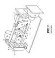
- the systemis large and complex as shown in FIG. 1 , and as such is unsuited for use in a compact camera system.
- the system as described in U.S. Pat. No. 5,717,512includes three mirrors, a pan and tilt mirror 34 , and two folding mirrors 58 and 59 to redirect the light collected from the scene by the pan and tilt mirror to the camera 60 .
- the systemalso includes three drive motors.
- the pan and tilt mirroris held in a frame 31 which can be rotated about the optical axis of the imaging lens 36 by pan drive motor 52 .
- the pan drive motor 52is mounted in pivot plate 53 which is rotatably attached to mounting plate 43 .
- the pan and tilt mirror 34can also be tilted by the tilt drive motor 44 which is attached to the pan and tilt mirror 34 by linkage 33 .
- the tilt drive motor 44is attached to pivot plate 53 so that it rotates with pan motions. Focusing of the image onto the camera is done by moving the imaging lens along the optical axis by focus motor 38 and along guide rods 39 .
- a camera systemis mounted on a rotating pivot for capturing overlapping images for a panoramic image.
- a sensoris included which indicates when each of the multiple images should be captured for good overlap.
- No prior art systemprovides a sufficiently compact, low cost, optical system with a large zoom range for a small, lightweight and relatively inexpensive consumer digital camera. It is additionally desirable to retain good image quality while avoiding substantial increases in the file size associated with a multiple image capture based process while still enabling a large zoom range.
- the inventionuses a moveable mirror to redirect the field of view for sequential image captures so that a wide angle image is constructed from sequential images which each have partially overlapping fields of view.
- the imagesare progressively binned as the number of images captured increases to keep the number of pixels and the readout time relatively constant throughout the zoom range. Further, the exposure time for each image is reduced as the images are progressively binned to keep the total exposure time relatively constant throughout the zoom range.
- the present inventionhas the advantage of providing a zoom module with a fixed focal length lens to reduce the cost of the lens while being compact in overall size. Another advantage provided by the invention is that a zoom module is provided that is compatible with a lens and sensor assembly that has been produced by wafer level manufacturing. A further advantage provided by the invention is that a flexible zoom system is provided from multiple image captures in such a way that the number of pixels in the formed composite image, the total readout and storage time, and the total exposure time are all kept relatively constant through the zoom range in spite of the multiple images that are captured.
- FIG. 1is perspective view of a prior art camera system with a motor driven pan and tilt action
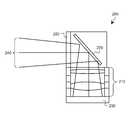
- FIG. 2is a side view of a cross section of the fixed focus lens and the moveable mirror as described in the present invention
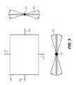
- FIG. 3is a diagram of the moveable mirror of the present invention.
- FIG. 4is a diagram of the layout and overlap of the multiple images as used throughout the zoom range for a 3 ⁇ zoom of the present invention.
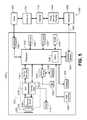
- FIG. 5is block diagram of an imaging system of the present invention using the imaging assembly of FIG. 2 .
- FIG. 2shows an embodiment of the present invention showing a zoom module 205 which is capable of capturing sequential images with different fields of view.
- a fixed focal length lens 210is combined with a moveable mirror 220 .
- the moveable mirror 220is positioned at substantially 45 degrees to the optical axis of the fixed focal length lens 210 so that the zoom module is relatively thin.
- Light rays 240from the scene being imaged, pass through a protective cover glass 250 , are reflected by the moveable mirror 220 , pass through the fixed focal length lens 210 , and are focused onto an image sensor array 230 where an electronic image is formed. The image is recorded by the pixels that make up the image sensor array 230 .
- An advantage of using a fixed focal length lens 210 in the zoom module 205is that fixed focal length lenses can be obtained that are very compact and at low cost, this is particularly true for lens assemblies made by wafer level manufacturing.
- the lens elementsare made many at a time in arrays that are bonded together and then diced to form individual lens assemblies as described in U.S. Pat. Nos. 6,235,141 and 6,610,166.
- Lens elements that are made in arrays for wafer level manufacturingare typically very simple in form and very small in size. Zoom lenses are not presently made by wafer level manufacturing.
- FIG. 3shows more detailed information about the moveable mirror.
- the reflective portion of the mirror 220can rotate independently about two perpendicular axes 315 and 317 so that a number of positions are possible.
- the two sideviews of the mirror shown in FIG. 3show the angular rotation of the mirror 220 rotating about the axes 315 and 317 .
- the mirror 220is capable of positions within a rotation range of +/ ⁇ 3 degrees to +/ ⁇ 12 degrees or more about the axes 315 and 317 .
- a rotation of a mirror about an axisprovides a 2 ⁇ deflection of the angle of the light that is reflected by the mirror, as a result, the field of view changes by +/ ⁇ 6 degrees to +/ ⁇ 24 degrees as described.
- multiple imagesare captured and stitched together to form a composite image with a wider angle perspective than would otherwise be possible with the fixed focal length lens alone.
- the moveable mirroris used to change the field of view between image captures.
- the number of images capturedis increased.
- the fields of view of the multiple imagesmust be at least partially overlapped to enable the images to be stitched together using stitching algorithms.
- FIG. 4shows some of the layouts of the multiple images that are possible for different zoom settings from 1 ⁇ to 3 ⁇ .
- a single image 410is captured with the moveable mirror set in the middle of its rotation range for both axes.
- four images of relative size 425are captured and merged into a single 2.5 ⁇ image layout 420 .
- image layout 420contains four images 425 which are illustrated with different types of lines some of which overlap.
- image layouts 430 , 440 and 450also contain multiple images illustrated with different types of lines, some of which overlap.
- the four imagesare captured sequentially with four different fields of view as provided by the moveable mirror moving sequentially between image captures.
- the image information from the respective fields of viewpartially overlap each other so that the portions of the four images that makeup the center of the 2.5 ⁇ image layout 420 are the same for all four images.
- the image information contained in the corners of the 2.5 ⁇ image layoutis made up from only one of the four images for each corner.
- the 2 ⁇ zoom layout 430comes from four images captured that are of a relative size 435 as shown and the amount of overlap between the four images can be less than for the 2.5 ⁇ zoom layout 420 .
- the technique for merging the four images togethercan be a combination of alignment of the images to one another, summing and averaging the pixel values in overlapping areas and electronically stitching.
- the present inventionincludes other methods for image layout such as the case wherein the amount of overlap between the multiple images is constant and the composite image is cropped to varying degrees for different zoom settings or zoom factors.
- the nine images of relative size 445are captured and merged into a single 1.5 ⁇ image layout 440 .
- the zoom settingdecreases, the number of images required to be captured increases and the relative size of the individual images captured as compared to the size of the composite image decreases.
- the plurality of images capturedis inversely proportional to the zoom factor.
- the relative size of the individual image captured for the 1.5 ⁇ zoom setting based on scene contentis approximately 1/9 th the size of the composite image formed when the individual images are merged.
- the zoom settingis 1 ⁇ and nine individual images of relative size 455 are captured and merged in a 1 ⁇ zoom layout 450 .
- the overlap between the individual images and their respective fields of viewis only a small amount so that the individual images can be stitched together to form a wider angle image without any gaps in the composite image.
- digital zoomcan be used for augmenting portions of the zoom range to provide a smoother transition between the number of captures.
- distortion within the individual images from the lenssuch as barrel or pincushion distortion
- off axis capture from the tilted mirrormay be corrected prior to stitching.
- low resolution preview imagessuch as those that are continuously displayed on the camera display for selecting the image composition
- the multiple imagesmay be cropped and stitched together to form a low resolution composite image based on the mirror locations without having to use complex stitching algorithms.
- the inventioncan be used for a wider zoom range as well by increasing the number of individual images captured and used to form a composite image with a wider field of view perspective such as 16 images in a 4 ⁇ 4 image layout for a 1 ⁇ to 4 ⁇ zoom range. It is important to note that the zoom range can be changed in the zoom system described by the present invention without having to change the fixed focal length lens since the multiple image approach provides a method for making images that are of a wider angle perspective limited only by the available movement of the moveable mirror.
- the fixed focal length lenscan be changed to change the effective focal length range that is associated with the zoom range to make the images substantially more telephoto or more wide angle.
- the multiple image approach of the present inventioncan be used to produce images that appear to have been captured by a zoom lens with a focal length range of 5-15 mm (substantially wide angle) by laying out the images as shown in FIG. 4 for a 1 ⁇ to 3 ⁇ zoom range.
- the multiple image approach of the present inventioncan be used to produce images that appear to have been captured by a zoom lens with a focal length range of 15-45 mm (substantially telephoto) by laying out the images as shown in FIG. 4 for a different 1 ⁇ to 3 ⁇ zoom range.
- the mirror positions associated with the different focal length rangeswould have to be adjusted to provide the desired degree of overlap between the multiple images.
- the present inventiondescribes a method of merging multiple images with partially overlapping fields of view as provided by a moveable mirror to form a composite image with a wider angle perspective.
- the example layouts of the multiple images as shown in FIG. 4are all of the same aspect ratio; however, different aspect ratio composite images can be created by changing the layout of the multiple images (such as to a 3 ⁇ 4 image layout) in the composite image to produce whatever aspect ratio or image shape is desired.
- the image sensor pixelsare binned in reverse correspondence to the zoom factor so that the total number of pixels in the composite image is kept relatively constant through the zoom range. It is noted that each individual image is captured with a different mirror position, and the binning factor is proportional to the number of mirror positions. Binning involves the electrical connection of neighboring pixels to share the electrical charge that is produced by the light on the pixels so that the binned pixel is effectively larger in area (and as such more sensitive to light) and the number of pixels in the individual image is reduced.
- the pixelswould be binned by 4 ⁇ during the image capture thereby reducing the number of pixels in each individual image to 1 ⁇ 4 th so that the total number of pixels contained in the four individual images is the same as the one image captured for the case of the 3 ⁇ zoom setting.
- the advantage of binning the sensor during the capture of the individual imagesis that the readout time of the image from the sensor is reduced. By keeping the total number of pixels from the multiple image capture set relatively constant, the time to readout the multiple individual images is kept relatively constant in spite of the multiple images being captured.
- only non-overlapping portions of the individual imagesare readout to further reduce the readout time.
- the large areas of overlap between the individual images(such as shown for the 2.5 ⁇ zoom layout in FIG. 4 ) are selected so that the image information for each portion of the composite image is only readout from one individual image.
- some small amount of overlap between imagesmust be maintained to insure good stitching between the individual images during the merging process to form the composite image.
- the exposure time for each individual imageis reduced to match the degree of binning for the image capture. Since binning effectively increases the area of each pixel, the light gathering capability or sensitivity of the pixel is increased proportionally. Consequently, reducing the exposure time to match the degree of binning results in the signal level and the relative noise level recorded by the pixel remaining constant for a given light level. Since the exposure time is reduced at the same rate as the pixels are binned and the binning matches the number of individual images captures in the multiple image capture set, the total exposure time for the multiple images remains relatively constant through the zoom range.
- the exposure time for each individual imagewould be reduced to 1 ⁇ 4 th so that the total exposure time for the four individual images is the same as the exposure time for the one individual image that is captured for the case of the 3 ⁇ zoom setting.
- a moveable MEMs mirror from Mirrorcle(model SO258DB with a 3.2 mm mirror, +/ ⁇ 6.6 degree movement and 5 millisecond movement time with no overshoot) is used with a telephoto lens that has a 12 degree field of view and an image sensor that has 5 megapixels.
- a telephoto lensthat has a 12 degree field of view
- an image sensorthat has 5 megapixels.
- For a 2 ⁇ zoom imagefour images are captured with four pixels binned together and an exposure time of 25 millisecond each.
- the mirroris moved (in degrees) in the following pan/tilt order during the capture of the multiple images: +3/+2; +3/ ⁇ 2; ⁇ 3/ ⁇ 2; ⁇ 3/+2.
- nine imagesare captured with nine pixels binned together and an exposure time of 11 millisecond each.
- the mirroris moved (in degrees) in the following pan/tilt order during the capture of the multiple images: +6/+4; +6/0; +6/ ⁇ 4; 0/ ⁇ 4; 0/0; 0/+4; ⁇ 6/+4; ⁇ 6/0; ⁇ 6/ ⁇ 4.
- FIG. 5is a block diagram of an imaging system that can be used with the image sensor assembly of present the invention.
- Imaging system 1200includes digital camera phone 1202 and computing device 1204 .
- Digital camera phone 1202is an example of an image capture device that can use an image sensor incorporating the present invention.
- Other types of image capture devicescan also be used with the present invention, such as, for example, digital still cameras and digital video camcorders.
- Digital camera phone 1202is a portable, handheld, battery-operated device in an embodiment in accordance with the invention.
- Digital camera phone 1202produces digital images that are stored in memory 1206 , which can be, for example, an internal Flash EPROM memory or a removable memory card.
- memory 1206can be, for example, an internal Flash EPROM memory or a removable memory card.
- Other types of digital image storage mediasuch as magnetic hard drives, magnetic tape, or optical disks, can alternatively be used to implement memory 1206 .
- Digital camera phone 1202uses mirror 220 and lens 210 to focus light from a scene (not shown) onto image sensor array 230 of sensor 1212 . Wherein mirror 220 , lens 210 and image sensor 230 are arranged as previously shown in FIG. 2 .
- Image sensor array 230provides color image information using the Bayer color filter pattern in an embodiment in accordance with the invention. Image sensor array 230 is controlled by timing generator 1214 , which also controls flash 1216 in order to illuminate the scene when the ambient illumination is low.
- the analog output signals output from the image sensor array 230are amplified and converted to digital data by analog-to-digital (A/D) converter circuit 1218 .
- the digital dataare stored in buffer memory 1220 and subsequently processed by digital processor 1222 .
- Digital processor 1222is controlled by the firmware stored in firmware memory 1224 , which can be flash EPROM memory.
- Digital processor 1222includes real-time clock 1226 , which keeps the date and time even when digital camera phone 1202 and digital processor 1222 are in a low power state.
- the processed digital image filesare stored in memory 1206 .
- Memory 1206can also store other types of data, such as, for example, music files (e.g. MP3 files), ring tones, phone numbers, calendars, and to-do lists.
- digital camera phone 1202captures still images.
- Digital processor 1222performs distortion correction, color interpolation followed by color and tone correction, in order to produce rendered sRGB image data.
- the rendered sRGB image dataare then compressed and stored as an image file in memory 1206 .
- the image datacan be compressed pursuant to the JPEG format, which uses the known “Exif” image format.
- This formatincludes an Exif application segment that stores particular image metadata using various TIFF tags. Separate TIFF tags can be used, for example, to store the date and time the picture was captured, the lens f/number and other camera settings, and to store image captions.
- Digital processor 1222produces different image sizes that are selected by the user in an embodiment in accordance with the invention.
- One such sizeis the low-resolution “thumbnail” size image.
- Generating thumbnail-size imagesis described in commonly assigned U.S. Pat. No. 5,164,831, entitled “Electronic Still Camera Providing Multi-Format Storage of Full and Reduced Resolution Images” to Kuchta, et al.
- the thumbnail imageis stored in RAM memory 1228 and supplied to color display 1230 , which can be, for example, an active matrix LCD or organic light emitting diode (OLED).
- Generating thumbnail size imagesallows the captured images to be reviewed quickly on color display 1230 .
- digital camera phone 1202also produces and stores video clips.
- a video clipis produced by summing multiple pixels of image sensor array 1210 together (e.g. summing pixels of the same color within each 4 column ⁇ 4 row area of the image sensor array 1210 ) to create a lower resolution video image frame.
- the video image framesare read from image sensor array 1210 at regular intervals, for example, using a 15 frame per second readout rate.
- Audio codec 1232is connected to digital processor 1222 and receives an audio signal from microphone (Mic) 1234 . Audio codec 1232 also provides an audio signal to speaker 1236 . These components are used both for telephone conversations and to record and playback an audio track, along with a video sequence or still image.
- Speaker 1236is also used to inform the user of an incoming phone call in an embodiment in accordance with the invention. This can be done using a standard ring tone stored in firmware memory 1224 , or by using a custom ring-tone downloaded from mobile phone network 1238 and stored in memory 1206 .
- a vibration device(not shown) can be used to provide a silent (e.g., non-audible) notification of an incoming phone call.
- Digital processor 1222is connected to wireless modem 1240 , which enables digital camera phone 1202 to transmit and receive information via radio frequency (RF) channel 1242 .
- Wireless modem 1240communicates with mobile phone network 1238 using another RF link (not shown), such as a 3GSM network.
- Mobile phone network 1238communicates with photo service provider 1244 , which stores digital images uploaded from digital camera phone 1202 .
- Other devices, including computing device 1204access these images via the Internet 1246 .
- Mobile phone network 1238also connects to a standard telephone network (not shown) in order to provide normal telephone service in an embodiment in accordance with the invention.
- a graphical user interface(not shown) is displayed on color display 1230 and controlled by user controls 1248 .
- User controls 1248include dedicated push buttons (e.g., a telephone keypad) to dial a phone number, a control to set the mode (e.g., “phone” mode, “calendar” mode” “camera” mode), a joystick controller that includes 4-way control (up, down, left, right), and a push-button center “OK” or “select” switch, in embodiments in accordance with the invention.
- Dock 1250recharges the batteries (not shown) in digital camera phone 1202 .
- Dock 1250connects digital camera phone 1202 to computing device 1204 via dock interface 1252 .
- Dock interface 1252is implemented as wired interface, such as a USB interface, in an embodiment in accordance with the invention.
- dock interface 1252is implemented as a wireless interface, such as a Bluetooth or an IEEE 802.11b wireless interface.
- Dock interface 1252is used to download images from memory 1206 to computing device 1204 .
- Dock interface 1252is also used to transfer calendar information from computing device 1204 to memory 1206 in digital camera phone 1202 .
- the stitching of the multiple images to form the composite imagecan be done within the digital camera phone 1202 by the processor 1222 or done remotely by the computer 1204 or by another processing device that the multiple images can be sent to through the wireless modem 1240 or interface 1252 .
Landscapes
- Engineering & Computer Science (AREA)
- Multimedia (AREA)
- Signal Processing (AREA)
- Human Computer Interaction (AREA)
- Studio Devices (AREA)
- Structure And Mechanism Of Cameras (AREA)
- Studio Circuits (AREA)
Abstract
Description
- 31 frame
- 33 linkage
- 34 pan and tilt mirror
- 36 imaging lens
- 38 focus motor
- 39 guide rods
- 43 mounting plate
- 44 tilt drive motor
- 52 pan drive motor
- 53 pivot plate
- 58 folding mirror
- 59 folding mirror
- 60 camera
- 205 zoom module
- 210 fixed focal length lens assembly
- 220 moveable mirror
- 230 image sensor array
- 240 light rays from the scene
- 250 cover glass
- 315 mirror axis of rotation
- 317 mirror axis of rotation
- 410 3× zoom layout
- 420 2.5× zoom layout
- 425 relative size of individual image for 2.5× zoom
- 430 2× zoom layout
- 435 relative size of individual image for 2× zoom
- 440 1.5× zoom layout
- 445 relative size of individual image for 1.5× zoom
- 450 1× zoom layout
- 455 relative size of individual image for 1× zoom
- 1200 imaging system
- 1202 digital camera phone
- 1204 computing device
- 1206 memory
- 1212 pixel sensor
- 1214 timing generator
- 1216 flash
- 1218 A/D converter circuit
- 1220 buffer memory
- 1222 digital processor
- 1224 firmware memory
- 1226 clock
- 1228 RAM memory
- 1230 color display
- 1232 audio codec
- 1234 microphone
- 1236 speaker
- 1238 mobile phone network
- 1240 wireless modem
- 1242 radio frequency (RF) channel
- 1244 photo service provider
- 1246 Internet
- 1248 user controls
- 1250 dock
- 1252 dock interface
Claims (17)
Priority Applications (6)
| Application Number | Priority Date | Filing Date | Title |
|---|---|---|---|
| US12/175,142US8134589B2 (en) | 2008-07-17 | 2008-07-17 | Zoom by multiple image capture |
| EP09788912AEP2301240A1 (en) | 2008-07-17 | 2009-06-14 | Zoom by multiple image capture |
| CN200980124903.8ACN102077575B (en) | 2008-07-17 | 2009-07-14 | Zoom via multiple image capture |
| JP2011518717AJP5499027B2 (en) | 2008-07-17 | 2009-07-14 | Zoom by capturing multiple images |
| PCT/US2009/004070WO2010008529A1 (en) | 2008-07-17 | 2009-07-14 | Zoom by multiple image capture |
| TW098124144ATWI465766B (en) | 2008-07-17 | 2009-07-16 | Image sensor assembly and image capture device |
Applications Claiming Priority (1)
| Application Number | Priority Date | Filing Date | Title |
|---|---|---|---|
| US12/175,142US8134589B2 (en) | 2008-07-17 | 2008-07-17 | Zoom by multiple image capture |
Publications (2)
| Publication Number | Publication Date |
|---|---|
| US20100013906A1 US20100013906A1 (en) | 2010-01-21 |
| US8134589B2true US8134589B2 (en) | 2012-03-13 |
Family
ID=40974575
Family Applications (1)
| Application Number | Title | Priority Date | Filing Date |
|---|---|---|---|
| US12/175,142Expired - Fee RelatedUS8134589B2 (en) | 2008-07-17 | 2008-07-17 | Zoom by multiple image capture |
Country Status (6)
| Country | Link |
|---|---|
| US (1) | US8134589B2 (en) |
| EP (1) | EP2301240A1 (en) |
| JP (1) | JP5499027B2 (en) |
| CN (1) | CN102077575B (en) |
| TW (1) | TWI465766B (en) |
| WO (1) | WO2010008529A1 (en) |
Cited By (9)
| Publication number | Priority date | Publication date | Assignee | Title |
|---|---|---|---|---|
| US9154697B2 (en) | 2013-12-06 | 2015-10-06 | Google Inc. | Camera selection based on occlusion of field of view |
| US9285566B2 (en) | 2013-08-08 | 2016-03-15 | Apple Inc. | Mirror tilt actuation |
| US9360671B1 (en) | 2014-06-09 | 2016-06-07 | Google Inc. | Systems and methods for image zoom |
| US9544574B2 (en) | 2013-12-06 | 2017-01-10 | Google Inc. | Selecting camera pairs for stereoscopic imaging |
| US9565416B1 (en) | 2013-09-30 | 2017-02-07 | Google Inc. | Depth-assisted focus in multi-camera systems |
| US9615012B2 (en) | 2013-09-30 | 2017-04-04 | Google Inc. | Using a second camera to adjust settings of first camera |
| US10812727B1 (en) | 2019-12-16 | 2020-10-20 | Cognex Corporation | Machine vision system and method with steerable mirror |
| US11647290B2 (en) | 2019-12-16 | 2023-05-09 | Cognex Corporation | Machine vision system and method with steerable mirror |
| US11790656B2 (en) | 2019-12-16 | 2023-10-17 | Cognex Corporation | Machine vision system and method with steerable mirror |
Families Citing this family (105)
| Publication number | Priority date | Publication date | Assignee | Title |
|---|---|---|---|---|
| JP5378135B2 (en)* | 2009-09-29 | 2013-12-25 | 富士フイルム株式会社 | Image layout determining method, program thereof, and information processing apparatus |
| US20160360121A1 (en)* | 2009-11-09 | 2016-12-08 | Yi-Chuan Cheng | Portable device with successive extension zooming capability |
| KR101125487B1 (en)* | 2010-09-30 | 2012-03-20 | 팅크웨어(주) | Mobile communication terminal, safety service system and method using same and recording medium recording the same |
| WO2012150378A1 (en) | 2011-05-02 | 2012-11-08 | Nokia Corporation | Methods and apparatuses for capturing an image |
| US20120293607A1 (en)* | 2011-05-17 | 2012-11-22 | Apple Inc. | Panorama Processing |
| CN108401113A (en) | 2012-05-07 | 2018-08-14 | 株式会社尼康 | Focus detection device |
| JP2013235047A (en)* | 2012-05-07 | 2013-11-21 | Nikon Corp | Focus detection device |
| JP6003198B2 (en)* | 2012-05-07 | 2016-10-05 | 株式会社ニコン | Focus detection device |
| CN112911252B (en) | 2012-11-28 | 2023-07-04 | 核心光电有限公司 | Multi-aperture imaging system |
| US9568713B2 (en) | 2013-01-05 | 2017-02-14 | Light Labs Inc. | Methods and apparatus for using multiple optical chains in parallel to support separate color-capture |
| FR3005168B1 (en)* | 2013-04-26 | 2015-04-10 | Thales Sa | METHOD FOR REMOVING PARASITE ECHOS IN SAR IMAGING |
| KR101634516B1 (en) | 2013-06-13 | 2016-06-28 | 코어포토닉스 리미티드 | Dual aperture zoom digital camera |
| JP2016523389A (en) | 2013-07-04 | 2016-08-08 | コアフォトニクス リミテッド | Compact telephoto lens assembly |
| EP4137868A1 (en)* | 2013-07-29 | 2023-02-22 | Bio-Rad Laboratories, Inc. | Mechanical zoom imaging apparatus and imaging method |
| CN108989649B (en) | 2013-08-01 | 2021-03-19 | 核心光电有限公司 | Slim multi-aperture imaging system with autofocus and method of use |
| US9549127B2 (en) | 2013-10-18 | 2017-01-17 | Light Labs Inc. | Image capture control methods and apparatus |
| US9851527B2 (en) | 2013-10-18 | 2017-12-26 | Light Labs Inc. | Methods and apparatus for capturing and/or combining images |
| CN105830425A (en)* | 2013-10-18 | 2016-08-03 | 泽莱特科股份有限公司 | Methods and apparatus for capturing and/or combining images |
| US9374514B2 (en) | 2013-10-18 | 2016-06-21 | The Lightco Inc. | Methods and apparatus relating to a camera including multiple optical chains |
| WO2015061769A1 (en)* | 2013-10-26 | 2015-04-30 | The Lightco Inc. | Methods and apparatus for use with multiple optical chains |
| US9736365B2 (en) | 2013-10-26 | 2017-08-15 | Light Labs Inc. | Zoom related methods and apparatus |
| US9467627B2 (en) | 2013-10-26 | 2016-10-11 | The Lightco Inc. | Methods and apparatus for use with multiple optical chains |
| US9426365B2 (en) | 2013-11-01 | 2016-08-23 | The Lightco Inc. | Image stabilization related methods and apparatus |
| WO2015066571A1 (en)* | 2013-11-01 | 2015-05-07 | The Lightco Inc. | Methods and apparatus relating to image stabilization |
| US9554031B2 (en) | 2013-12-31 | 2017-01-24 | Light Labs Inc. | Camera focusing related methods and apparatus |
| US10931866B2 (en) | 2014-01-05 | 2021-02-23 | Light Labs Inc. | Methods and apparatus for receiving and storing in a camera a user controllable setting that is used to control composite image generation performed after image capture |
| KR102209066B1 (en)* | 2014-01-17 | 2021-01-28 | 삼성전자주식회사 | Method and apparatus for image composition using multiple focal length |
| US9638163B2 (en)* | 2014-02-20 | 2017-05-02 | General Electric Company | Methods and systems for removing and/or installing wind turbine rotor blades |
| US20150244949A1 (en)* | 2014-02-21 | 2015-08-27 | Rajiv Laroia | Illumination methods and apparatus |
| US9979878B2 (en) | 2014-02-21 | 2018-05-22 | Light Labs Inc. | Intuitive camera user interface methods and apparatus |
| CN106575366A (en) | 2014-07-04 | 2017-04-19 | 光实验室股份有限公司 | Method and apparatus for detecting and/or indicating dirty lens condition |
| US10110794B2 (en) | 2014-07-09 | 2018-10-23 | Light Labs Inc. | Camera device including multiple optical chains and related methods |
| US9392188B2 (en) | 2014-08-10 | 2016-07-12 | Corephotonics Ltd. | Zoom dual-aperture camera with folded lens |
| WO2016061565A1 (en) | 2014-10-17 | 2016-04-21 | The Lightco Inc. | Methods and apparatus for using a camera device to support multiple modes of operation |
| WO2016100756A1 (en) | 2014-12-17 | 2016-06-23 | The Lightco Inc. | Methods and apparatus for implementing and using camera devices |
| US9544503B2 (en) | 2014-12-30 | 2017-01-10 | Light Labs Inc. | Exposure control methods and apparatus |
| CN112433331B (en) | 2015-01-03 | 2022-07-08 | 核心光电有限公司 | Miniature telephoto lens module and camera using the same |
| CN107407849B (en) | 2015-04-02 | 2018-11-06 | 核心光电有限公司 | Dual Voice Coil Coil Motor Structure in Dual Optical Module Camera |
| US9824427B2 (en) | 2015-04-15 | 2017-11-21 | Light Labs Inc. | Methods and apparatus for generating a sharp image |
| CN112394467B (en) | 2015-04-16 | 2023-06-09 | 核心光电有限公司 | Autofocus and Optical Image Stabilization in a Compact Folding Camera |
| US9857584B2 (en) | 2015-04-17 | 2018-01-02 | Light Labs Inc. | Camera device methods, apparatus and components |
| US10075651B2 (en) | 2015-04-17 | 2018-09-11 | Light Labs Inc. | Methods and apparatus for capturing images using multiple camera modules in an efficient manner |
| US9967535B2 (en) | 2015-04-17 | 2018-05-08 | Light Labs Inc. | Methods and apparatus for reducing noise in images |
| US10091447B2 (en) | 2015-04-17 | 2018-10-02 | Light Labs Inc. | Methods and apparatus for synchronizing readout of multiple image sensors |
| US9930233B2 (en) | 2015-04-22 | 2018-03-27 | Light Labs Inc. | Filter mounting methods and apparatus and related camera apparatus |
| CN110687655B (en) | 2015-05-28 | 2022-10-21 | 核心光电有限公司 | Bi-directional stiffness for optical image stabilization and auto-focus in dual aperture digital cameras |
| US10129483B2 (en) | 2015-06-23 | 2018-11-13 | Light Labs Inc. | Methods and apparatus for implementing zoom using one or more moveable camera modules |
| US10491806B2 (en) | 2015-08-03 | 2019-11-26 | Light Labs Inc. | Camera device control related methods and apparatus |
| US10230898B2 (en) | 2015-08-13 | 2019-03-12 | Corephotonics Ltd. | Dual aperture zoom camera with video support and switching / non-switching dynamic control |
| US10365480B2 (en) | 2015-08-27 | 2019-07-30 | Light Labs Inc. | Methods and apparatus for implementing and/or using camera devices with one or more light redirection devices |
| EP3474070B1 (en) | 2015-09-06 | 2020-06-24 | Corephotonics Ltd. | Auto focus and optical image stabilization with roll compensation in a compact folded camera |
| CN106559616B (en)* | 2015-09-30 | 2020-08-28 | 日本电气株式会社 | Single lens imaging method and apparatus |
| US10051182B2 (en) | 2015-10-05 | 2018-08-14 | Light Labs Inc. | Methods and apparatus for compensating for motion and/or changing light conditions during image capture |
| US9749549B2 (en) | 2015-10-06 | 2017-08-29 | Light Labs Inc. | Methods and apparatus for facilitating selective blurring of one or more image portions |
| US10225445B2 (en) | 2015-12-18 | 2019-03-05 | Light Labs Inc. | Methods and apparatus for providing a camera lens or viewing point indicator |
| US10003738B2 (en) | 2015-12-18 | 2018-06-19 | Light Labs Inc. | Methods and apparatus for detecting and/or indicating a blocked sensor or camera module |
| KR102369223B1 (en) | 2015-12-29 | 2022-03-02 | 코어포토닉스 리미티드 | Dual-aperture zoom digital camera with automatic adjustable tele field of view |
| US10306218B2 (en) | 2016-03-22 | 2019-05-28 | Light Labs Inc. | Camera calibration apparatus and methods |
| US20170294033A1 (en)* | 2016-04-06 | 2017-10-12 | Varex Imaging Corporation | Dose efficient x-ray detector and method |
| KR102002718B1 (en) | 2016-05-30 | 2019-10-18 | 코어포토닉스 리미티드 | Rotary Ball-Guid Voice Coil Motor |
| KR20240036133A (en) | 2016-06-19 | 2024-03-19 | 코어포토닉스 리미티드 | Frame synchronization in a dual-aperture camera system |
| US9948832B2 (en) | 2016-06-22 | 2018-04-17 | Light Labs Inc. | Methods and apparatus for synchronized image capture in a device including optical chains with different orientations |
| KR20240051317A (en) | 2016-07-07 | 2024-04-19 | 코어포토닉스 리미티드 | Linear ball guided voice coil motor for folded optic |
| US10706518B2 (en) | 2016-07-07 | 2020-07-07 | Corephotonics Ltd. | Dual camera system with improved video smooth transition by image blending |
| US10616493B2 (en) | 2016-08-31 | 2020-04-07 | Huawei Technologies Co., Ltd. | Multi camera system for zoom |
| EP3842853B1 (en) | 2016-12-28 | 2024-03-06 | Corephotonics Ltd. | Folded camera structure with an extended light-folding-element scanning range |
| US10884321B2 (en) | 2017-01-12 | 2021-01-05 | Corephotonics Ltd. | Compact folded camera |
| KR102212611B1 (en) | 2017-02-23 | 2021-02-05 | 코어포토닉스 리미티드 | Folded camera lens designs |
| KR102530535B1 (en) | 2017-03-15 | 2023-05-08 | 코어포토닉스 리미티드 | Cameras with panoramic scanning range |
| US10670858B2 (en) | 2017-05-21 | 2020-06-02 | Light Labs Inc. | Methods and apparatus for maintaining and accurately determining the position of a moveable element |
| US10373362B2 (en)* | 2017-07-06 | 2019-08-06 | Humaneyes Technologies Ltd. | Systems and methods for adaptive stitching of digital images |
| US10863135B2 (en)* | 2017-07-12 | 2020-12-08 | Dell Products L.P. | Information handling system integrated multi-angle camera |
| WO2019048904A1 (en) | 2017-09-06 | 2019-03-14 | Corephotonics Ltd. | Combined stereoscopic and phase detection depth mapping in a dual aperture camera |
| US10951834B2 (en) | 2017-10-03 | 2021-03-16 | Corephotonics Ltd. | Synthetically enlarged camera aperture |
| US11333955B2 (en) | 2017-11-23 | 2022-05-17 | Corephotonics Ltd. | Compact folded camera structure |
| CN114609746A (en) | 2018-02-05 | 2022-06-10 | 核心光电有限公司 | Folding camera device |
| CN113568251B (en) | 2018-02-12 | 2022-08-30 | 核心光电有限公司 | Digital camera and method for providing focus and compensating for camera tilt |
| US10694168B2 (en) | 2018-04-22 | 2020-06-23 | Corephotonics Ltd. | System and method for mitigating or preventing eye damage from structured light IR/NIR projector systems |
| KR20250053984A (en) | 2018-04-23 | 2025-04-22 | 코어포토닉스 리미티드 | An optical-path folding-element with an extended two degree of freedom rotation range |
| CN108427185B (en)* | 2018-05-15 | 2023-07-14 | 嘉兴中润光学科技股份有限公司 | Rotatable optical system |
| CN119919618A (en) | 2018-07-04 | 2025-05-02 | 核心光电有限公司 | Cameras with folded scanning beam path for automotive or surveillance applications |
| CN111316346B (en) | 2018-08-04 | 2022-11-29 | 核心光电有限公司 | Switchable continuous display information system above camera |
| US11635596B2 (en) | 2018-08-22 | 2023-04-25 | Corephotonics Ltd. | Two-state zoom folded camera |
| US11108973B2 (en)* | 2018-10-05 | 2021-08-31 | Essential Products, Inc. | Varying a zoom level of an image recorded with a lens having a fixed zoom level |
| US11287081B2 (en) | 2019-01-07 | 2022-03-29 | Corephotonics Ltd. | Rotation mechanism with sliding joint |
| EP4224841B1 (en) | 2019-03-09 | 2025-06-25 | Corephotonics Ltd. | Method for dynamic stereoscopic calibration |
| US11368631B1 (en) | 2019-07-31 | 2022-06-21 | Corephotonics Ltd. | System and method for creating background blur in camera panning or motion |
| CN112468684B (en)* | 2019-09-09 | 2025-05-09 | 北京小米移动软件有限公司 | Camera module and mobile terminal having the same |
| US11659135B2 (en) | 2019-10-30 | 2023-05-23 | Corephotonics Ltd. | Slow or fast motion video using depth information |
| CN114641983A (en) | 2019-12-09 | 2022-06-17 | 核心光电有限公司 | System and method for obtaining intelligent panoramic image |
| US11949976B2 (en) | 2019-12-09 | 2024-04-02 | Corephotonics Ltd. | Systems and methods for obtaining a smart panoramic image |
| EP4546027A3 (en) | 2020-02-22 | 2025-08-13 | Corephotonics Ltd. | Split screen feature for macro photography |
| EP4097773A4 (en) | 2020-04-26 | 2023-11-01 | Corephotonics Ltd. | TEMPERATURE CONTROL FOR HALL BAR SENSOR CORRECTION |
| CN117372249A (en) | 2020-05-17 | 2024-01-09 | 核心光电有限公司 | Image stitching of full field of view reference images |
| US11770609B2 (en) | 2020-05-30 | 2023-09-26 | Corephotonics Ltd. | Systems and methods for obtaining a super macro image |
| KR102862382B1 (en)* | 2020-07-15 | 2025-09-18 | 코어포토닉스 리미티드 | Point of view aberrations correction in a scanning folded camera |
| US11637977B2 (en) | 2020-07-15 | 2023-04-25 | Corephotonics Ltd. | Image sensors and sensing methods to obtain time-of-flight and phase detection information |
| CN118433505A (en) | 2020-07-31 | 2024-08-02 | 核心光电有限公司 | camera |
| WO2022034402A1 (en) | 2020-08-12 | 2022-02-17 | Corephotonics Ltd. | Optical image stabilization in a scanning folded camera |
| CN114675474A (en)* | 2020-12-24 | 2022-06-28 | 成都极米科技股份有限公司 | Switching type micro-actuating part and micro-actuating device |
| KR102696960B1 (en) | 2020-12-26 | 2024-08-19 | 코어포토닉스 리미티드 | Video support in a multi-aperture mobile camera with a scanning zoom camera |
| KR102589548B1 (en) | 2021-03-11 | 2023-10-13 | 코어포토닉스 리미티드 | Pop-out camera system |
| US12007671B2 (en) | 2021-06-08 | 2024-06-11 | Corephotonics Ltd. | Systems and cameras for tilting a focal plane of a super-macro image |
| GB2617427A (en)* | 2021-12-06 | 2023-10-11 | Mbda Uk Ltd | Apparatus and method for imaging |
| US12328505B2 (en) | 2022-03-24 | 2025-06-10 | Corephotonics Ltd. | Slim compact lens optical image stabilization |
Citations (37)
| Publication number | Priority date | Publication date | Assignee | Title |
|---|---|---|---|---|
| US5164831A (en) | 1990-03-15 | 1992-11-17 | Eastman Kodak Company | Electronic still camera providing multi-format storage of full and reduced resolution images |
| US5200860A (en)* | 1988-06-09 | 1993-04-06 | Canon Kabushiki Kaisha | Lens position control device |
| US5270780A (en)* | 1991-09-13 | 1993-12-14 | Science Applications International Corporation | Dual detector lidar system and method |
| US5657402A (en) | 1991-11-01 | 1997-08-12 | Massachusetts Institute Of Technology | Method of creating a high resolution still image using a plurality of images and apparatus for practice of the method |
| US5717512A (en) | 1996-05-15 | 1998-02-10 | Chmielewski, Jr.; Thomas A. | Compact image steering and focusing device |
| US5973726A (en)* | 1993-09-24 | 1999-10-26 | Canon Kabushiki Kaisha | Panoramic image processing apparatus |
| US6034716A (en)* | 1997-12-18 | 2000-03-07 | Whiting; Joshua B. | Panoramic digital camera system |
| US6235141B1 (en) | 1996-09-27 | 2001-05-22 | Digital Optics Corporation | Method of mass producing and packaging integrated optical subsystems |
| US6304284B1 (en)* | 1998-03-31 | 2001-10-16 | Intel Corporation | Method of and apparatus for creating panoramic or surround images using a motion sensor equipped camera |
| US20020075258A1 (en) | 1999-05-12 | 2002-06-20 | Imove Inc. | Camera system with high resolution image inside a wide angle view |
| US20030004584A1 (en)* | 2001-06-27 | 2003-01-02 | Hallett Jeffrey A. | User interface for a gamma camera which acquires multiple simultaneous data sets |
| US20030001099A1 (en)* | 2001-06-27 | 2003-01-02 | Coles David E. | Multiple simultaneous acquisition of gamma camera data sets |
| US6610166B1 (en)* | 1997-10-03 | 2003-08-26 | Digital Optics Corporation | Method for replicating optical elements, particularly on a wafer level, and replicas formed thereby |
| US20030160789A1 (en)* | 2002-02-28 | 2003-08-28 | Tang Yan Yan | Multiple scan line sample filtering |
| US6639625B1 (en)* | 1997-07-16 | 2003-10-28 | Minolta Co., Ltd. | Image sensing device |
| WO2004084542A1 (en) | 2003-03-20 | 2004-09-30 | Seijiro Tomita | Panoramic picture creating method and device, and monitor system using the method and device |
| US20060011724A1 (en)* | 2004-07-15 | 2006-01-19 | Eugene Joseph | Optical code reading system and method using a variable resolution imaging sensor |
| US20060119732A1 (en)* | 1997-12-19 | 2006-06-08 | Canon Kabushiki Kaisha | Optical equipment and its control method, and computer-readable storage medium |
| US20060125937A1 (en)* | 2004-12-10 | 2006-06-15 | Ambarella, Inc. | High resolution zoom: a novel digital zoom for digital video camera |
| US7064783B2 (en) | 1999-12-31 | 2006-06-20 | Stmicroelectronics, Inc. | Still picture format for subsequent picture stitching for forming a panoramic image |
| US20070081081A1 (en) | 2005-10-07 | 2007-04-12 | Cheng Brett A | Automated multi-frame image capture for panorama stitching using motion sensor |
| US7245443B2 (en)* | 2004-08-17 | 2007-07-17 | Olympus Corporation | Panoramic attachment optical system, and panoramic optical system |
| US7277118B2 (en)* | 1999-08-09 | 2007-10-02 | Fuji Xerox Co., Ltd. | Method and system for compensating for parallax in multiple camera systems |
| US20070263113A1 (en) | 2006-05-09 | 2007-11-15 | Stereo Display, Inc. | High resolution imaging system |
| US7317473B2 (en) | 1998-05-27 | 2008-01-08 | Ju-Wei Chen | Image-based method and system for building spherical panoramas |
| US20080068451A1 (en)* | 2006-09-20 | 2008-03-20 | Sony Ericsson Mobile Communications Ab | Rotating prism for a digital camera in a portable mobile communication device |
| US20080111881A1 (en)* | 2006-11-09 | 2008-05-15 | Innovative Signal Analysis, Inc. | Imaging system |
| US7382399B1 (en)* | 1991-05-13 | 2008-06-03 | Sony Coporation | Omniview motionless camera orientation system |
| US20080247745A1 (en) | 2007-04-04 | 2008-10-09 | Nilsson Rene | Camera assembly with zoom imaging and method |
| US7474731B2 (en)* | 2006-08-29 | 2009-01-06 | Siemens Medical Solutions Usa, Inc. | Systems and methods for adaptive image processing using acquisition data and calibration/model data |
| US7495694B2 (en)* | 2004-07-28 | 2009-02-24 | Microsoft Corp. | Omni-directional camera with calibration and up look angle improvements |
| US20090073254A1 (en)* | 2007-09-17 | 2009-03-19 | Hui Li | Omnidirectional imaging system with concurrent zoom |
| US7609289B2 (en)* | 2003-09-25 | 2009-10-27 | Omnitek Partners, Llc | Methods and apparatus for capturing images with a multi-image lens |
| US7623781B1 (en)* | 2004-03-05 | 2009-11-24 | Mega Vision Corporation | Image shooting apparatus |
| US20100002071A1 (en)* | 2004-04-30 | 2010-01-07 | Grandeye Ltd. | Multiple View and Multiple Object Processing in Wide-Angle Video Camera |
| US7848628B2 (en)* | 2005-12-08 | 2010-12-07 | Sony Corporation | Camera system, camera control apparatus, panorama image making method and computer program product |
| US20100328505A1 (en)* | 2008-03-28 | 2010-12-30 | Panasonic Corporation | Imaging device, imaging module and imaging system |
Family Cites Families (7)
| Publication number | Priority date | Publication date | Assignee | Title |
|---|---|---|---|---|
| JPH1141509A (en)* | 1997-07-16 | 1999-02-12 | Minolta Co Ltd | Image pickup device |
| JP2004093504A (en)* | 2002-09-03 | 2004-03-25 | Topcon Corp | Surveying equipment |
| US7576767B2 (en)* | 2004-07-26 | 2009-08-18 | Geo Semiconductors Inc. | Panoramic vision system and method |
| CN1878297A (en)* | 2005-06-07 | 2006-12-13 | 浙江工业大学 | Omnibearing vision device |
| JP2008017090A (en)* | 2006-07-05 | 2008-01-24 | Casio Comput Co Ltd | Imaging apparatus and electronic zoom method |
| JP4855192B2 (en)* | 2006-09-14 | 2012-01-18 | 富士フイルム株式会社 | Image sensor and digital camera |
| CN101221351B (en)* | 2007-11-23 | 2010-08-25 | 浙江大学 | Panoramic scanning and imaging method and system based on colored CCD |
- 2008
- 2008-07-17USUS12/175,142patent/US8134589B2/ennot_activeExpired - Fee Related
- 2009
- 2009-06-14EPEP09788912Apatent/EP2301240A1/ennot_activeWithdrawn
- 2009-07-14JPJP2011518717Apatent/JP5499027B2/ennot_activeExpired - Fee Related
- 2009-07-14CNCN200980124903.8Apatent/CN102077575B/ennot_activeExpired - Fee Related
- 2009-07-14WOPCT/US2009/004070patent/WO2010008529A1/enactiveApplication Filing
- 2009-07-16TWTW098124144Apatent/TWI465766B/ennot_activeIP Right Cessation
Patent Citations (38)
| Publication number | Priority date | Publication date | Assignee | Title |
|---|---|---|---|---|
| US5200860A (en)* | 1988-06-09 | 1993-04-06 | Canon Kabushiki Kaisha | Lens position control device |
| US5164831A (en) | 1990-03-15 | 1992-11-17 | Eastman Kodak Company | Electronic still camera providing multi-format storage of full and reduced resolution images |
| US7382399B1 (en)* | 1991-05-13 | 2008-06-03 | Sony Coporation | Omniview motionless camera orientation system |
| US5270780A (en)* | 1991-09-13 | 1993-12-14 | Science Applications International Corporation | Dual detector lidar system and method |
| US5657402A (en) | 1991-11-01 | 1997-08-12 | Massachusetts Institute Of Technology | Method of creating a high resolution still image using a plurality of images and apparatus for practice of the method |
| US5973726A (en)* | 1993-09-24 | 1999-10-26 | Canon Kabushiki Kaisha | Panoramic image processing apparatus |
| US5717512A (en) | 1996-05-15 | 1998-02-10 | Chmielewski, Jr.; Thomas A. | Compact image steering and focusing device |
| US6235141B1 (en) | 1996-09-27 | 2001-05-22 | Digital Optics Corporation | Method of mass producing and packaging integrated optical subsystems |
| US6639625B1 (en)* | 1997-07-16 | 2003-10-28 | Minolta Co., Ltd. | Image sensing device |
| US6610166B1 (en)* | 1997-10-03 | 2003-08-26 | Digital Optics Corporation | Method for replicating optical elements, particularly on a wafer level, and replicas formed thereby |
| US6034716A (en)* | 1997-12-18 | 2000-03-07 | Whiting; Joshua B. | Panoramic digital camera system |
| US20060119732A1 (en)* | 1997-12-19 | 2006-06-08 | Canon Kabushiki Kaisha | Optical equipment and its control method, and computer-readable storage medium |
| US6304284B1 (en)* | 1998-03-31 | 2001-10-16 | Intel Corporation | Method of and apparatus for creating panoramic or surround images using a motion sensor equipped camera |
| US7317473B2 (en) | 1998-05-27 | 2008-01-08 | Ju-Wei Chen | Image-based method and system for building spherical panoramas |
| US20020075258A1 (en) | 1999-05-12 | 2002-06-20 | Imove Inc. | Camera system with high resolution image inside a wide angle view |
| US7277118B2 (en)* | 1999-08-09 | 2007-10-02 | Fuji Xerox Co., Ltd. | Method and system for compensating for parallax in multiple camera systems |
| US7064783B2 (en) | 1999-12-31 | 2006-06-20 | Stmicroelectronics, Inc. | Still picture format for subsequent picture stitching for forming a panoramic image |
| US20030004584A1 (en)* | 2001-06-27 | 2003-01-02 | Hallett Jeffrey A. | User interface for a gamma camera which acquires multiple simultaneous data sets |
| US20030001099A1 (en)* | 2001-06-27 | 2003-01-02 | Coles David E. | Multiple simultaneous acquisition of gamma camera data sets |
| US20030160789A1 (en)* | 2002-02-28 | 2003-08-28 | Tang Yan Yan | Multiple scan line sample filtering |
| WO2004084542A1 (en) | 2003-03-20 | 2004-09-30 | Seijiro Tomita | Panoramic picture creating method and device, and monitor system using the method and device |
| US7609289B2 (en)* | 2003-09-25 | 2009-10-27 | Omnitek Partners, Llc | Methods and apparatus for capturing images with a multi-image lens |
| US7623781B1 (en)* | 2004-03-05 | 2009-11-24 | Mega Vision Corporation | Image shooting apparatus |
| US20100002071A1 (en)* | 2004-04-30 | 2010-01-07 | Grandeye Ltd. | Multiple View and Multiple Object Processing in Wide-Angle Video Camera |
| US20070102520A1 (en)* | 2004-07-15 | 2007-05-10 | Symbol Technologies, Inc. | Optical code reading system and method for processing multiple resolution representations of an image |
| US20060011724A1 (en)* | 2004-07-15 | 2006-01-19 | Eugene Joseph | Optical code reading system and method using a variable resolution imaging sensor |
| US7495694B2 (en)* | 2004-07-28 | 2009-02-24 | Microsoft Corp. | Omni-directional camera with calibration and up look angle improvements |
| US7245443B2 (en)* | 2004-08-17 | 2007-07-17 | Olympus Corporation | Panoramic attachment optical system, and panoramic optical system |
| US20060125937A1 (en)* | 2004-12-10 | 2006-06-15 | Ambarella, Inc. | High resolution zoom: a novel digital zoom for digital video camera |
| US20070081081A1 (en) | 2005-10-07 | 2007-04-12 | Cheng Brett A | Automated multi-frame image capture for panorama stitching using motion sensor |
| US7848628B2 (en)* | 2005-12-08 | 2010-12-07 | Sony Corporation | Camera system, camera control apparatus, panorama image making method and computer program product |
| US20070263113A1 (en) | 2006-05-09 | 2007-11-15 | Stereo Display, Inc. | High resolution imaging system |
| US7474731B2 (en)* | 2006-08-29 | 2009-01-06 | Siemens Medical Solutions Usa, Inc. | Systems and methods for adaptive image processing using acquisition data and calibration/model data |
| US20080068451A1 (en)* | 2006-09-20 | 2008-03-20 | Sony Ericsson Mobile Communications Ab | Rotating prism for a digital camera in a portable mobile communication device |
| US20080111881A1 (en)* | 2006-11-09 | 2008-05-15 | Innovative Signal Analysis, Inc. | Imaging system |
| US20080247745A1 (en) | 2007-04-04 | 2008-10-09 | Nilsson Rene | Camera assembly with zoom imaging and method |
| US20090073254A1 (en)* | 2007-09-17 | 2009-03-19 | Hui Li | Omnidirectional imaging system with concurrent zoom |
| US20100328505A1 (en)* | 2008-03-28 | 2010-12-30 | Panasonic Corporation | Imaging device, imaging module and imaging system |
Cited By (16)
| Publication number | Priority date | Publication date | Assignee | Title |
|---|---|---|---|---|
| US11347076B2 (en) | 2013-08-08 | 2022-05-31 | Apple Inc. | Mirror tilt actuation |
| US9285566B2 (en) | 2013-08-08 | 2016-03-15 | Apple Inc. | Mirror tilt actuation |
| US10162191B2 (en) | 2013-08-08 | 2018-12-25 | Apple Inc. | Mirror tilt actuation |
| US10712581B2 (en) | 2013-08-08 | 2020-07-14 | Apple Inc. | Mirror tilt actuation |
| US9632327B2 (en) | 2013-08-08 | 2017-04-25 | Apple Inc. | Mirror tilt actuation |
| US9565416B1 (en) | 2013-09-30 | 2017-02-07 | Google Inc. | Depth-assisted focus in multi-camera systems |
| US9615012B2 (en) | 2013-09-30 | 2017-04-04 | Google Inc. | Using a second camera to adjust settings of first camera |
| US9544574B2 (en) | 2013-12-06 | 2017-01-10 | Google Inc. | Selecting camera pairs for stereoscopic imaging |
| US9154697B2 (en) | 2013-12-06 | 2015-10-06 | Google Inc. | Camera selection based on occlusion of field of view |
| US9918065B2 (en) | 2014-01-29 | 2018-03-13 | Google Llc | Depth-assisted focus in multi-camera systems |
| US9360671B1 (en) | 2014-06-09 | 2016-06-07 | Google Inc. | Systems and methods for image zoom |
| US10812727B1 (en) | 2019-12-16 | 2020-10-20 | Cognex Corporation | Machine vision system and method with steerable mirror |
| US11240436B2 (en) | 2019-12-16 | 2022-02-01 | Cognex Corporation | Machine vision system and method with steerable mirror |
| US11647290B2 (en) | 2019-12-16 | 2023-05-09 | Cognex Corporation | Machine vision system and method with steerable mirror |
| US11790656B2 (en) | 2019-12-16 | 2023-10-17 | Cognex Corporation | Machine vision system and method with steerable mirror |
| US11803049B2 (en) | 2019-12-16 | 2023-10-31 | Cognex Corporation | Machine vision system and method with steerable mirror |
Also Published As
| Publication number | Publication date |
|---|---|
| JP2011528531A (en) | 2011-11-17 |
| TWI465766B (en) | 2014-12-21 |
| JP5499027B2 (en) | 2014-05-21 |
| TW201009386A (en) | 2010-03-01 |
| US20100013906A1 (en) | 2010-01-21 |
| WO2010008529A1 (en) | 2010-01-21 |
| CN102077575B (en) | 2014-07-09 |
| CN102077575A (en) | 2011-05-25 |
| EP2301240A1 (en) | 2011-03-30 |
Similar Documents
| Publication | Publication Date | Title |
|---|---|---|
| US8134589B2 (en) | Zoom by multiple image capture | |
| US7256944B2 (en) | Compact image capture assembly using multiple lenses and image sensors to provide an extended zoom range | |
| US7305180B2 (en) | Digital camera using multiple lenses and image sensors to provide an extended zoom range | |
| US7561191B2 (en) | Camera phone using multiple lenses and image sensors to provide an extended zoom range | |
| US7236306B2 (en) | Digital camera using an express zooming mode to provide expedited operation over an extended zoom range | |
| US8593564B2 (en) | Digital camera including refocusable imaging mode adaptor | |
| US20060187322A1 (en) | Digital camera using multiple fixed focal length lenses and multiple image sensors to provide an extended zoom range | |
| US20080030592A1 (en) | Producing digital image with different resolution portions | |
| US20130076966A1 (en) | Digital imaging system with refocusable imaging mode | |
| US20130076931A1 (en) | Plenoptic lens unit providing refocusable imaging mode | |
| US20090303377A1 (en) | Image sensors with improved angle response | |
| JP4569389B2 (en) | Imaging apparatus, image processing method, and program | |
| JP2006081089A (en) | Imaging device | |
| JP4003172B2 (en) | Image signal processing apparatus and electronic camera | |
| JP4003171B2 (en) | Electronic camera | |
| JP4879513B2 (en) | Imaging device | |
| WO2013043488A1 (en) | Digital imaging system with refocusable imaging mode | |
| JP2004064350A (en) | Mobile phone with imaging device | |
| JP2003008959A (en) | Imaging device and mode selection method thereof | |
| JP4272823B2 (en) | Imaging device | |
| JP2000287116A (en) | Image capture system |
Legal Events
| Date | Code | Title | Description |
|---|---|---|---|
| AS | Assignment | Owner name:EASTMAN KODAK COMPANY,NEW YORK Free format text:ASSIGNMENT OF ASSIGNORS INTEREST;ASSIGNORS:BORDER, JOHN N.;BIETRY, JOSEPH R.;SIGNING DATES FROM 20080716 TO 20080717;REEL/FRAME:021255/0206 Owner name:EASTMAN KODAK COMPANY, NEW YORK Free format text:ASSIGNMENT OF ASSIGNORS INTEREST;ASSIGNORS:BORDER, JOHN N.;BIETRY, JOSEPH R.;SIGNING DATES FROM 20080716 TO 20080717;REEL/FRAME:021255/0206 | |
| FEPP | Fee payment procedure | Free format text:PAYER NUMBER DE-ASSIGNED (ORIGINAL EVENT CODE: RMPN); ENTITY STATUS OF PATENT OWNER: LARGE ENTITY Free format text:PAYOR NUMBER ASSIGNED (ORIGINAL EVENT CODE: ASPN); ENTITY STATUS OF PATENT OWNER: LARGE ENTITY | |
| AS | Assignment | Owner name:CITICORP NORTH AMERICA, INC., AS AGENT, NEW YORK Free format text:SECURITY INTEREST;ASSIGNORS:EASTMAN KODAK COMPANY;PAKON, INC.;REEL/FRAME:028201/0420 Effective date:20120215 | |
| STCF | Information on status: patent grant | Free format text:PATENTED CASE | |
| AS | Assignment | Owner name:FPC INC., CALIFORNIA Free format text:PATENT RELEASE;ASSIGNORS:CITICORP NORTH AMERICA, INC.;WILMINGTON TRUST, NATIONAL ASSOCIATION;REEL/FRAME:029913/0001 Effective date:20130201 Owner name:KODAK AVIATION LEASING LLC, NEW YORK Free format text:PATENT RELEASE;ASSIGNORS:CITICORP NORTH AMERICA, INC.;WILMINGTON TRUST, NATIONAL ASSOCIATION;REEL/FRAME:029913/0001 Effective date:20130201 Owner name:EASTMAN KODAK COMPANY, NEW YORK Free format text:PATENT RELEASE;ASSIGNORS:CITICORP NORTH AMERICA, INC.;WILMINGTON TRUST, NATIONAL ASSOCIATION;REEL/FRAME:029913/0001 Effective date:20130201 Owner name:KODAK REALTY, INC., NEW YORK Free format text:PATENT RELEASE;ASSIGNORS:CITICORP NORTH AMERICA, INC.;WILMINGTON TRUST, NATIONAL ASSOCIATION;REEL/FRAME:029913/0001 Effective date:20130201 Owner name:KODAK AMERICAS, LTD., NEW YORK Free format text:PATENT RELEASE;ASSIGNORS:CITICORP NORTH AMERICA, INC.;WILMINGTON TRUST, NATIONAL ASSOCIATION;REEL/FRAME:029913/0001 Effective date:20130201 Owner name:CREO MANUFACTURING AMERICA LLC, WYOMING Free format text:PATENT RELEASE;ASSIGNORS:CITICORP NORTH AMERICA, INC.;WILMINGTON TRUST, NATIONAL ASSOCIATION;REEL/FRAME:029913/0001 Effective date:20130201 Owner name:NPEC INC., NEW YORK Free format text:PATENT RELEASE;ASSIGNORS:CITICORP NORTH AMERICA, INC.;WILMINGTON TRUST, NATIONAL ASSOCIATION;REEL/FRAME:029913/0001 Effective date:20130201 Owner name:KODAK IMAGING NETWORK, INC., CALIFORNIA Free format text:PATENT RELEASE;ASSIGNORS:CITICORP NORTH AMERICA, INC.;WILMINGTON TRUST, NATIONAL ASSOCIATION;REEL/FRAME:029913/0001 Effective date:20130201 Owner name:QUALEX INC., NORTH CAROLINA Free format text:PATENT RELEASE;ASSIGNORS:CITICORP NORTH AMERICA, INC.;WILMINGTON TRUST, NATIONAL ASSOCIATION;REEL/FRAME:029913/0001 Effective date:20130201 Owner name:EASTMAN KODAK INTERNATIONAL CAPITAL COMPANY, INC., Free format text:PATENT RELEASE;ASSIGNORS:CITICORP NORTH AMERICA, INC.;WILMINGTON TRUST, NATIONAL ASSOCIATION;REEL/FRAME:029913/0001 Effective date:20130201 Owner name:LASER-PACIFIC MEDIA CORPORATION, NEW YORK Free format text:PATENT RELEASE;ASSIGNORS:CITICORP NORTH AMERICA, INC.;WILMINGTON TRUST, NATIONAL ASSOCIATION;REEL/FRAME:029913/0001 Effective date:20130201 Owner name:KODAK (NEAR EAST), INC., NEW YORK Free format text:PATENT RELEASE;ASSIGNORS:CITICORP NORTH AMERICA, INC.;WILMINGTON TRUST, NATIONAL ASSOCIATION;REEL/FRAME:029913/0001 Effective date:20130201 Owner name:PAKON, INC., INDIANA Free format text:PATENT RELEASE;ASSIGNORS:CITICORP NORTH AMERICA, INC.;WILMINGTON TRUST, NATIONAL ASSOCIATION;REEL/FRAME:029913/0001 Effective date:20130201 Owner name:KODAK PHILIPPINES, LTD., NEW YORK Free format text:PATENT RELEASE;ASSIGNORS:CITICORP NORTH AMERICA, INC.;WILMINGTON TRUST, NATIONAL ASSOCIATION;REEL/FRAME:029913/0001 Effective date:20130201 Owner name:FAR EAST DEVELOPMENT LTD., NEW YORK Free format text:PATENT RELEASE;ASSIGNORS:CITICORP NORTH AMERICA, INC.;WILMINGTON TRUST, NATIONAL ASSOCIATION;REEL/FRAME:029913/0001 Effective date:20130201 Owner name:KODAK PORTUGUESA LIMITED, NEW YORK Free format text:PATENT RELEASE;ASSIGNORS:CITICORP NORTH AMERICA, INC.;WILMINGTON TRUST, NATIONAL ASSOCIATION;REEL/FRAME:029913/0001 Effective date:20130201 | |
| AS | Assignment | Owner name:INTELLECTUAL VENTURES FUND 83 LLC, NEVADA Free format text:ASSIGNMENT OF ASSIGNORS INTEREST;ASSIGNOR:EASTMAN KODAK COMPANY;REEL/FRAME:030224/0001 Effective date:20130201 | |
| FPAY | Fee payment | Year of fee payment:4 | |
| AS | Assignment | Owner name:MONUMENT PEAK VENTURES, LLC, TEXAS Free format text:ASSIGNMENT OF ASSIGNORS INTEREST;ASSIGNOR:INTELLECTUAL VENTURES FUND 83 LLC;REEL/FRAME:041941/0079 Effective date:20170215 | |
| FEPP | Fee payment procedure | Free format text:MAINTENANCE FEE REMINDER MAILED (ORIGINAL EVENT CODE: REM.); ENTITY STATUS OF PATENT OWNER: LARGE ENTITY | |
| LAPS | Lapse for failure to pay maintenance fees | Free format text:PATENT EXPIRED FOR FAILURE TO PAY MAINTENANCE FEES (ORIGINAL EVENT CODE: EXP.); ENTITY STATUS OF PATENT OWNER: LARGE ENTITY | |
| STCH | Information on status: patent discontinuation | Free format text:PATENT EXPIRED DUE TO NONPAYMENT OF MAINTENANCE FEES UNDER 37 CFR 1.362 | |
| FP | Lapsed due to failure to pay maintenance fee | Effective date:20200313 | |
| AS | Assignment | Owner name:MONUMENT PEAK VENTURES, LLC, TEXAS Free format text:RELEASE BY SECURED PARTY;ASSIGNOR:INTELLECTUAL VENTURES FUND 83 LLC;REEL/FRAME:064599/0304 Effective date:20230728 |