US8134334B2 - Vehicle - Google Patents
VehicleDownload PDFInfo
- Publication number
- US8134334B2 US8134334B2US12/449,716US44971608AUS8134334B2US 8134334 B2US8134334 B2US 8134334B2US 44971608 AUS44971608 AUS 44971608AUS 8134334 B2US8134334 B2US 8134334B2
- Authority
- US
- United States
- Prior art keywords
- vehicle
- electric power
- unit
- illumination unit
- space
- Prior art date
- Legal status (The legal status is an assumption and is not a legal conclusion. Google has not performed a legal analysis and makes no representation as to the accuracy of the status listed.)
- Expired - Fee Related, expires
Links
- 238000005286illuminationMethods0.000claimsabstractdescription27
- 238000004891communicationMethods0.000claimsdescription5
- 230000004308accommodationEffects0.000abstractdescription26
- 230000005540biological transmissionEffects0.000abstractdescription10
- 230000008878couplingEffects0.000abstractdescription3
- 238000010168coupling processMethods0.000abstractdescription3
- 238000005859coupling reactionMethods0.000abstractdescription3
- 230000007935neutral effectEffects0.000description7
- 239000000446fuelSubstances0.000description6
- XYDVHKCVOMGRSY-UHFFFAOYSA-N4-(4-benzylphenyl)-1,3-thiazol-2-amineChemical compoundS1C(N)=NC(C=2C=CC(CC=3C=CC=CC=3)=CC=2)=C1XYDVHKCVOMGRSY-UHFFFAOYSA-N0.000description4
- 101000928034Homo sapiens Proteasomal ubiquitin receptor ADRM1Proteins0.000description4
- 102100036915Proteasomal ubiquitin receptor ADRM1Human genes0.000description4
- 238000007599dischargingMethods0.000description3
- 239000000945fillerSubstances0.000description3
- 101150036497AEBP1 geneProteins0.000description2
- 101001050286Homo sapiens Jupiter microtubule associated homolog 1Proteins0.000description2
- 102100023133Jupiter microtubule associated homolog 1Human genes0.000description2
- 239000003990capacitorSubstances0.000description2
- 238000003780insertionMethods0.000description2
- 230000037431insertionEffects0.000description2
- XLYOFNOQVPJJNP-UHFFFAOYSA-NwaterSubstancesOXLYOFNOQVPJJNP-UHFFFAOYSA-N0.000description2
- HBBGRARXTFLTSG-UHFFFAOYSA-NLithium ionChemical compound[Li+]HBBGRARXTFLTSG-UHFFFAOYSA-N0.000description1
- 230000002457bidirectional effectEffects0.000description1
- 238000006243chemical reactionMethods0.000description1
- 239000003086colorantSubstances0.000description1
- 238000002485combustion reactionMethods0.000description1
- 239000000428dustSubstances0.000description1
- 230000006870functionEffects0.000description1
- 229910052739hydrogenInorganic materials0.000description1
- 239000001257hydrogenSubstances0.000description1
- 229910001416lithium ionInorganic materials0.000description1
- 238000000034methodMethods0.000description1
- 238000012986modificationMethods0.000description1
- 230000004048modificationEffects0.000description1
- 238000012545processingMethods0.000description1
Images


Classifications
- B—PERFORMING OPERATIONS; TRANSPORTING
- B60—VEHICLES IN GENERAL
- B60Q—ARRANGEMENT OF SIGNALLING OR LIGHTING DEVICES, THE MOUNTING OR SUPPORTING THEREOF OR CIRCUITS THEREFOR, FOR VEHICLES IN GENERAL
- B60Q1/00—Arrangement of optical signalling or lighting devices, the mounting or supporting thereof or circuits therefor
- B60Q1/26—Arrangement of optical signalling or lighting devices, the mounting or supporting thereof or circuits therefor the devices being primarily intended to indicate the vehicle, or parts thereof, or to give signals, to other traffic
- B60Q1/2661—Arrangement of optical signalling or lighting devices, the mounting or supporting thereof or circuits therefor the devices being primarily intended to indicate the vehicle, or parts thereof, or to give signals, to other traffic mounted on parts having other functions
- B—PERFORMING OPERATIONS; TRANSPORTING
- B60—VEHICLES IN GENERAL
- B60Q—ARRANGEMENT OF SIGNALLING OR LIGHTING DEVICES, THE MOUNTING OR SUPPORTING THEREOF OR CIRCUITS THEREFOR, FOR VEHICLES IN GENERAL
- B60Q3/00—Arrangement of lighting devices for vehicle interiors; Lighting devices specially adapted for vehicle interiors
- B60Q3/30—Arrangement of lighting devices for vehicle interiors; Lighting devices specially adapted for vehicle interiors for compartments other than passenger or driving compartments, e.g. luggage or engine compartments
Definitions
- the present inventionrelates to a vehicle capable of utilizing electric power supplied from an external power source, and particularly relates to a user-friendly structure for performing external charging.
- a so-called electric-powered vehiclesuch as an electric vehicle, a hybrid vehicle, or a fuel-cell vehicle is mounted with a power storage device made of a secondary battery, a capacitor, or the like, and travels by generating driving force from electric power stored in the relevant power storage device.
- An electric vehicledoes not have an electric power-generating function configured with an engine and others, and thus it has conventionally been required to store electric power to be used for traveling in the power storage device mounted thereon, with use of electric power of an external power source such as a commercial power source.
- an electric-powered vehiclesuch as a hybrid vehicle or a fuel-cell vehicle, which has an electric power-generating mechanism
- attentionhas been focused on a configuration that uses a commercial power source supplied to each household and having a relatively low voltage (e.g. 100 V or 200 V) to charge the power storage device mounted on the electric-powered vehicle.
- a lighting fixtureIn the case of externally charging the electric-powered vehicle in each household, a lighting fixture is not always fully equipped, in contrast to the case of resupplying fuel at the fueling station. Accordingly, from the viewpoint of further facilitating an operation of coupling an electric power-feeding unit (a typical example of which is a charging connector) for supplying electric power of the external power source to the electric-powered vehicle at night or the like, there has been disclosed a configuration in which a lighting fixture is provided at the vehicle or at the electric power-feeding unit.
- an electric power-feeding unita typical example of which is a charging connector
- the userhas to search for the position of the charging port with the help of light emitted from a charging connector, as disclosed in Japanese Patent Laying-Open No. 09-161898, and thus resulting in a problem of causing the user to feel burdensome.
- the present inventionhas been made to solve such problems, and an object of the present invention is to provide a vehicle that enables a position of the charging port provided at the vehicle body to be easily specified and enables the electric power-feeding unit to be easily coupled to the relevant charging port, even if vehicle surroundings are dark such as at night.
- the accommodation chamberincludes a surface formed to be concave with respect to the vehicle external surface.
- the illumination unitis disposed on a vertically upper side of the accommodation chamber.
- the lid unitis configured to be rotatable about an axis of rotation extending in parallel with one side of the opening of the accommodation chamber.
- FIG. 2is a schematic configurational view of the vehicle according to the embodiment of the present invention.
- FIG. 3is a zero-phase equivalent circuit of inverters and motor generators in a zero-phase mode.
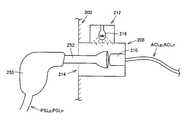
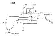
- FIGS. 4A and 4Bare external views of a charging port according to the embodiment of the present invention.
- vehicle 100is typically a parallel/series-type hybrid vehicle, and includes an engine ENG operated by combustion of fuel, a first motor generator MG 1 capable of generating electric power by receiving a part of motive power from engine ENG, and a second motor generator MG 2 operating as an electric motor by electric power supplied from at least a power storage device (BAT) 4 .
- Engine ENG and motor generators MG 1 and MG 2are mechanically coupled to one another via a power split device 22 , which is typically made of a planetary gear mechanism.
- Vehicle 100further includes a first inverter (INV 1 ) 8 - 1 and a second inverter (INV 2 ) 8 - 2 made to correspond to motor generators MG 1 and MG 2 , respectively.
- Inverters 8 - 1 and 8 - 2are electrically connected in parallel with respect to power storage device 4 , and when vehicle 100 travels (i.e. when external charging is not performed), make conversion between direct-current electric power and alternating-current electric power.
- Power storage device 4is a rechargeable electric power storage element, and is configured with a secondary battery such as a lithium-ion battery or a nickel-hydrogen battery, or a storage element such as an electric double layer capacitor, as an example.
- Step-up/down converter (CONV) 6 for allowing direct-current voltage to be stepped up and stepped downis disposed between power storage device 4 and inverters 8 - 1 and 8 - 2 , and allows an input/output voltage of power storage device 4 and a line voltage between main positive bus MPL and main negative bus MNL to be converted bi-directionally.
- the step-up/down operations at step-up/down converter 6are controlled in accordance with a switching command PWC from control unit 2 .
- the configuration of a hybrid vehicle serving as the vehicleis not limited to the above-described configuration.
- a so-called parallel-type hybrid vehicle or series-type hybrid vehiclemay also be adopted.
- the number of motor generatorsmay also be set freely as appropriate, and the configuration mounted with only a single motor generator (electric motor) may also be adopted as in most parallel-type hybrid vehicles.
- a DC/DC converter 20is electrically connected in parallel to step-up/down converter 6 with respect to power storage device 4 .
- DC/DC converter 20steps down electric power discharged from power storage device 4 to generate auxiliary equipment electric power.
- the voltage of auxiliary equipment electric poweris set to be lower (e.g. 12V or 24V) than the charging and discharging voltage of the power storage device (e.g. 288 V).
- the auxiliary equipment electric power generated at DC/DC converter 20is supplied to various auxiliary equipment of vehicle 100 , not shown, via a low-voltage supply line DCL, and a part of it is supplied to an auxiliary equipment battery SB.
- Auxiliary equipment battery SBis a rechargeable electric power storage element that stores auxiliary equipment electric power. With use of auxiliary equipment battery SB, auxiliary equipment electric power can be supplied to each of auxiliary equipment, even if vehicle 100 is in a halt state (ignition off state).
- a charging connector 250which is a typical example of an electric power-feeding unit, is coupled to charging port 200 ( FIG. 1 ). More specifically, charging connector 250 is mechanically coupled to and electrically connected to an electric power-receiving unit 210 accommodated in charging port 200 , to form an electrical input path between the external power source and power storage device 4 .
- a single-phase alternating-current commercial power source(its voltage value is approximately 100 V to 200 V) is used as an external power source.
- a single-phase alternating-current commercial power sourceis received in vehicle 100 via a neutral point N 1 of motor generator MG 1 and a neutral point N 2 of motor generator MG 2 , to externally charge power storage device 4 .
- supply lines PSLp and PSLn that transport electric power from the external power sourceare electrically connected to neutral point N 1 of motor generator MG 1 and neutral point N 2 of motor generator MG 2 via electric power-receiving lines ACLp and ACLn, respectively.
- Each of motor generators MG 1 and MG 2includes a stator made of Y-connected (star-connected) three-phase coils. A point at which these coils are connected to one another in the Y-connection corresponds to each of neutral points N 1 and N 2 of motor generators MG 1 and MG 2 .
- Electric power of the external power sourceis supplied to neutral points N 1 and N 2 of motor generators MG 1 and MG 2 , so that a voltage value of supply line PSLp is applied to respective phases of first inverter 8 - 1 at the alternating-current ports, and a voltage value of supply line PSLn is applied to respective phases of second inverter 8 - 2 at the alternating-current ports.
- Inverters 8 - 1 and 8 - 2are then allowed to appropriately perform a switching operation, so that direct-current electric power having a prescribed voltage value is supplied from inverters 8 - 1 and 8 - 2 to main positive bus MPL and main negative bus MNL.
- the three upper arm circuitscan be regarded as being in the same switching state (all of them are on or off), and the three lower arm circuits can also be regarded as being in the same switching state.
- the respective phase voltagescan be equal to one another.
- Such a switching modeis also referred to as a zero-phase mode.
- FIG. 3is a zero-phase equivalent circuit of inverters 8 - 1 and 8 - 2 and motor generators MG 1 and MG 2 in a zero-phase mode.
- charging port 200includes an accommodation unit 208 formed to be concave with respect to the vehicle external surface of vehicle body 300 .
- Accommodation unit 208has an electric power-receiving unit 210 disposed therein, the electric power receiving unit 210 being formed to be cylindrical.
- Electric power-receiving unit 210protrudes such that its one end can be fitted into a coupler unit 252 of a charging connector 250 .
- a chamberis formed from the vehicle external surface of vehicle body 300 toward an inside of the vehicle body, and electric power-receiving unit 210 is disposed at the innermost of the relevant chamber.
- Such an accommodation unit 208may be formed integrally with the vehicle external surface (body surface), or alternatively, accommodation unit 208 having a prescribed accommodation chamber may be attached into an aperture made by removing a part of the vehicle external surface.
- the “surface formed to be concave with respect to the vehicle external surface.”also includes the case that a hole is formed at a part of the vehicle external surface and a box is attached to cover an opening of the hole from an inner surface side of the vehicle body.
- Opening/closing lid 204 provided at an exterior part of vehicle body 300is rotatably supported by a support unit 206 , and its turning operation allows an opening 214 of accommodation unit 208 to be closed or opened.
- opening/closing lid 204can rotate about an axis of rotation extending in parallel with one side of opening 214 of accommodation unit 208 .
- an aperture portionis formed at a central portion of opening/closing lid 204 , and light transmission member 202 is disposed at the relevant aperture portion.
- FIGS. 4A and 4Billustrate a light transmission member having an approximately rectangular cross-sectional shape taken in a vertical direction, the cross-sectional shape of the light transmission member may be of any shape.
- an illumination unit 212 for applying light to an inside of accommodation unit 208is provided in proximity to accommodation unit 208 .
- Illumination unit 212may be disposed at any position as long as it can apply light to accommodation unit 208 .
- Illumination unit 212has a chamber being in communication with accommodation unit 208 , and a light source 216 is disposed in the relevant chamber.
- illumination unit 212is configured with a surface formed to be concave with respect to one of the surfaces formed to be concave with respect to the vehicle external surface, which surfaces configure accommodation unit 208 .
- Light source 216is made of a filament lamp, an LED (Light Emitting Diode), and the like, as an example, and is lit by auxiliary equipment electric power supplied from auxiliary equipment battery SB ( FIG. 2 )
- illumination unit 212illuminates a space formed of accommodation unit 208 , and facilitates a user's operation of coupling charging connector 250 to electric power-receiving unit 210 .
- the leaked lightenables a user to visually perceive the position of charging port 200 at a glance even if opening/closing lid 204 is in a closed state. Therefore, even if vehicle surroundings are dark such as at night, a user can assuredly specify the position of charging port 200 , and hence can easily couple charging connector 250 to electric power-receiving unit 210 .
- an object of the present inventionis to enable a user to grasp the position of charging port 200 at a glance, even if opening/closing lid 204 is in a closed state. Therefore, even if opening/closing lid 204 is in a closed state, illumination unit 212 is lit. As such, the timing at which illumination unit 212 is lit can be controlled by radio communication means or the like between vehicle 100 and charging connector 250 .
Landscapes
- Engineering & Computer Science (AREA)
- Mechanical Engineering (AREA)
- Electric Propulsion And Braking For Vehicles (AREA)
- Charge And Discharge Circuits For Batteries Or The Like (AREA)
Abstract
Description
Claims (4)
Applications Claiming Priority (3)
| Application Number | Priority Date | Filing Date | Title |
|---|---|---|---|
| JP2007101811AJP4830953B2 (en) | 2007-04-09 | 2007-04-09 | vehicle |
| JP2007-101811 | 2007-04-09 | ||
| PCT/JP2008/057230WO2008126930A1 (en) | 2007-04-09 | 2008-04-08 | Vehicle |
Publications (2)
| Publication Number | Publication Date |
|---|---|
| US20100026238A1 US20100026238A1 (en) | 2010-02-04 |
| US8134334B2true US8134334B2 (en) | 2012-03-13 |
Family
ID=39864022
Family Applications (1)
| Application Number | Title | Priority Date | Filing Date |
|---|---|---|---|
| US12/449,716Expired - Fee RelatedUS8134334B2 (en) | 2007-04-09 | 2008-04-08 | Vehicle |
Country Status (4)
| Country | Link |
|---|---|
| US (1) | US8134334B2 (en) |
| JP (1) | JP4830953B2 (en) |
| CN (1) | CN101652271B (en) |
| WO (1) | WO2008126930A1 (en) |
Cited By (11)
| Publication number | Priority date | Publication date | Assignee | Title |
|---|---|---|---|---|
| US20100246198A1 (en)* | 2009-03-27 | 2010-09-30 | Hook Richard R | Illuminated Bezel of Charge Port for Electric Vehicle |
| US20120212967A1 (en)* | 2011-02-21 | 2012-08-23 | Yazaki Corporation | Illumination unit for charging connector |
| US9197072B2 (en) | 2011-11-28 | 2015-11-24 | Toyoda Gosei Co., Ltd. | Charging device including a housing recess |
| US20170267117A1 (en)* | 2016-03-18 | 2017-09-21 | Ford Global Technologies, Llc | Hybrid/electric vehicle charge port door |
| US20190106005A1 (en)* | 2015-03-31 | 2019-04-11 | Audi Ag | Motor vehicle comprising an electrical energy store and two charging interfaces, charging system and method |
| US10746575B2 (en) | 2018-08-13 | 2020-08-18 | Magna Mirrors Holding Gmbh | Outside mirror side turn indicator with integrated battery charge display function |
| US10766379B2 (en) | 2017-05-18 | 2020-09-08 | Hyundai Motor Company | Charging apparatus for vehicle |
| US11072252B2 (en)* | 2018-06-19 | 2021-07-27 | Volkswagen Aktiengesellschaft | Charging port cover and/or fuel cap module for a motor vehicle |
| US11424581B2 (en)* | 2020-03-16 | 2022-08-23 | GM Global Technology Operations LLC | Electric vehicle charge port illumination module |
| US11472300B2 (en) | 2020-03-23 | 2022-10-18 | Ford Global Technologies, Llc | Charge port illumination system and illumination method |
| DE102023002904B3 (en) | 2023-07-17 | 2024-07-18 | Mercedes-Benz Group AG | Method for producing a loading trough for a vehicle |
Families Citing this family (52)
| Publication number | Priority date | Publication date | Assignee | Title |
|---|---|---|---|---|
| JP4894611B2 (en) | 2007-05-11 | 2012-03-14 | トヨタ自動車株式会社 | vehicle |
| US8226284B2 (en)* | 2009-05-29 | 2012-07-24 | GM Global Technology Operations LLC | Electric charge receptacle with illumination feature |
| JP5229184B2 (en)* | 2009-10-13 | 2013-07-03 | トヨタ自動車株式会社 | Vehicle lighting device |
| JP5452164B2 (en)* | 2009-10-21 | 2014-03-26 | 新明和工業株式会社 | Mechanical parking facility with charging function |
| JP5359854B2 (en)* | 2009-12-25 | 2013-12-04 | トヨタ自動車株式会社 | vehicle |
| KR101124954B1 (en)* | 2010-06-28 | 2012-03-27 | 현대자동차주식회사 | Cover apparatus for battery charge port of electric vehicle |
| DE102010053137A1 (en)* | 2010-12-01 | 2012-06-06 | Volkswagen Ag | Charging interface for an electric vehicle |
| US9457673B2 (en)* | 2011-04-12 | 2016-10-04 | Toyota Jidosha Kabushiki Kaisha | Electric vehicle with charging port illumination |
| WO2013016540A1 (en) | 2011-07-26 | 2013-01-31 | Gogoro, Inc. | Apparatus, method and article for collection, charging and distributing power storage devices, such as batteries |
| JP6422119B2 (en) | 2011-07-26 | 2018-11-14 | ゴゴロ インク | Apparatus, method and article for redistributing a power storage device such as a battery between collection charge distribution devices |
| TWI485572B (en) | 2011-07-26 | 2015-05-21 | 睿能創意公司 | Apparatus, method and article for physical preservation of power storage devices in vehicles |
| US9424697B2 (en) | 2011-07-26 | 2016-08-23 | Gogoro Inc. | Apparatus, method and article for a power storage device compartment |
| ES2748199T3 (en) | 2011-07-26 | 2020-03-13 | Gogoro Inc | Apparatus, method and article for providing information on the availability of energy storage devices in an energy storage device collection, charging and dispensing machine |
| TWI584976B (en) | 2011-07-26 | 2017-06-01 | 睿能創意公司 | Dynamically limiting vehicle operation for best effort economy |
| US10186094B2 (en) | 2011-07-26 | 2019-01-22 | Gogoro Inc. | Apparatus, method and article for providing locations of power storage device collection, charging and distribution machines |
| CN103891089B (en) | 2011-07-26 | 2016-10-12 | 睿能创意公司 | Apparatus, method and article for authentication, security and control of electric power storage devices such as batteries |
| JP6026535B2 (en) | 2011-07-26 | 2016-11-16 | ゴゴロ インク | RESERVED POWER STORAGE DEVICE DEVICE, METHOD, AND ARTICLE FOR RESERVING A POWER STORAGE DEVICE IN A COLLECTION, CHARGING AND DISTRIBUTION MACHINE |
| TWI486909B (en) | 2011-07-26 | 2015-06-01 | 睿能創意公司 | Apparatus, method and article for providing vehicle diagnostic data |
| WO2013016570A1 (en) | 2011-07-26 | 2013-01-31 | Gogoro, Inc. | Apparatus, method and article for authentication, security and control of power storage devices, such as batteries, based on user profiles |
| DE102011080455A1 (en)* | 2011-08-04 | 2013-02-07 | Siemens Ag | Arrangement for insertion of plug of cable from charging station into plug connector for e.g. electric car, has lighting unit provided in plug and located in vicinity of plug connector so as to illuminate plug connector |
| US8825250B2 (en)* | 2011-10-05 | 2014-09-02 | Gogoro, Inc. | Detectible indication of an electric motor vehicle standby mode |
| ES2692526T3 (en) | 2011-11-08 | 2018-12-04 | Gogoro Inc. | Apparatus, method and article for vehicle safety |
| JP2014050193A (en)* | 2012-08-30 | 2014-03-17 | Toyota Motor Corp | Vehicle mounted with secondary battery |
| JP5884699B2 (en)* | 2012-09-28 | 2016-03-15 | 三菱自動車工業株式会社 | Charging connector housing device for truck electric vehicle |
| DE102012019605A1 (en)* | 2012-10-05 | 2014-04-10 | Audi Ag | Modular system for a loading device, loading device and vehicle with a loading device created from the modular system |
| EP2920027B1 (en) | 2012-11-16 | 2021-10-13 | Gogoro Inc. | System and method for vehicle turn signals |
| US9854438B2 (en) | 2013-03-06 | 2017-12-26 | Gogoro Inc. | Apparatus, method and article for authentication, security and control of portable charging devices and power storage devices, such as batteries |
| DE102013004219A1 (en)* | 2013-03-11 | 2014-09-11 | Man Truck & Bus Ag | Motor vehicle with plug-in charger |
| US11222485B2 (en) | 2013-03-12 | 2022-01-11 | Gogoro Inc. | Apparatus, method and article for providing information regarding a vehicle via a mobile device |
| EP2973941A4 (en) | 2013-03-12 | 2016-09-14 | Gogoro Inc | APPARATUS, METHOD AND ARTICLE DESIGNED TO MODIFY EXCHANGE PLANS OF PORTABLE ELECTRIC POWER STORAGE DEVICE |
| US11075530B2 (en) | 2013-03-15 | 2021-07-27 | Gogoro Inc. | Modular system for collection and distribution of electric storage devices |
| EP3030453B1 (en) | 2013-08-06 | 2019-06-19 | Gogoro Inc. | Systems and methods for powering electric vehicles using a single or multiple power cells |
| CN108189701B (en) | 2013-08-06 | 2021-10-22 | 睿能创意公司 | Regulation of electric vehicle systems based on electrical energy storage device thermal profiles |
| US9124085B2 (en) | 2013-11-04 | 2015-09-01 | Gogoro Inc. | Apparatus, method and article for power storage device failure safety |
| ES2777275T3 (en) | 2013-11-08 | 2020-08-04 | Gogoro Inc | Apparatus, method and article to provide vehicle event data |
| ES2721000T3 (en) | 2014-01-23 | 2019-07-26 | Gogoro Inc | Systems and methods for using a set of energy storage devices, such as batteries |
| CN106605338B (en) | 2014-08-11 | 2019-07-16 | 睿能创意公司 | Multidirectional electric connector, plug and system |
| USD789883S1 (en) | 2014-09-04 | 2017-06-20 | Gogoro Inc. | Collection, charging and distribution device for portable electrical energy storage devices |
| CN107873006B (en) | 2015-06-05 | 2021-02-02 | 睿能创意公司 | Vehicle and method for determining a specific type of load of an electric vehicle |
| US10000132B2 (en)* | 2016-02-22 | 2018-06-19 | Ford Global Technologies, Llc | Charging indicator light control |
| CN105905051B (en)* | 2016-05-09 | 2018-03-30 | 重庆长安汽车股份有限公司 | Fuel tank cap and charging hatchcover interlock system, interlock method and hybrid vehicle |
| JP6905400B2 (en) | 2016-09-08 | 2021-07-21 | 株式会社ニフコ | Vehicle lighting device |
| DE102016223010B4 (en)* | 2016-11-22 | 2024-09-26 | Audi Ag | Locking device for covering and releasing a charging interface of a motor vehicle and motor vehicle |
| JP6786562B2 (en) | 2018-09-27 | 2020-11-18 | 本田技研工業株式会社 | Vehicle port device |
| JP6734337B2 (en)* | 2018-09-27 | 2020-08-05 | 本田技研工業株式会社 | Body front structure |
| EP4043273A4 (en)* | 2019-10-09 | 2022-12-07 | NISSAN MOTOR Co., Ltd. | CHARGING PORT DEVICE FOR VEHICLE |
| IT202100002699A1 (en) | 2021-02-08 | 2022-08-08 | Te Connectivity Italia Distribution Srl | MODULAR LIGHTING SYSTEM FOR POWER SOCKETS |
| DE102021210405A1 (en)* | 2021-08-06 | 2023-02-09 | Bos Gmbh & Co. Kg | Energy supply connection for arrangement in the area of an outer contour of an electric motor vehicle and electric motor vehicle |
| DE102021122948A1 (en)* | 2021-09-06 | 2023-03-09 | Dr. Ing. H.C. F. Porsche Aktiengesellschaft | Electric vehicle with a charging flap module |
| KR20230044703A (en)* | 2021-09-27 | 2023-04-04 | 현대자동차주식회사 | System and method for lighting charging port of electric vehicle |
| DE102023130794A1 (en)* | 2022-11-22 | 2024-05-23 | Autosystems, A Division Of Magna Exteriors Inc. | VEHICLE LIGHTING SYSTEM |
| CN118833137A (en)* | 2024-08-07 | 2024-10-25 | 奇瑞新能源汽车股份有限公司 | Electric automobile lamp language control method, system, equipment and medium |
Citations (8)
| Publication number | Priority date | Publication date | Assignee | Title |
|---|---|---|---|---|
| JPH06325834A (en) | 1993-05-11 | 1994-11-25 | Sumitomo Wiring Syst Ltd | Charging connector in electric automobile |
| JPH0787607A (en) | 1993-09-14 | 1995-03-31 | Honda Motor Co Ltd | Electric vehicle charging display device |
| JPH09161898A (en) | 1995-11-30 | 1997-06-20 | Yazaki Corp | Electric vehicle charging connector |
| JP2001244028A (en) | 2000-02-28 | 2001-09-07 | Kanto Auto Works Ltd | Vehicular external power code |
| US6424099B1 (en)* | 1999-07-02 | 2002-07-23 | Fusion Lighting, Inc. | High output lamp with high brightness |
| JP2004106624A (en) | 2002-09-17 | 2004-04-08 | Nishikawa Kasei Co Ltd | Mounting structure for glove box lighting |
| JP2006117207A (en) | 2004-10-25 | 2006-05-11 | Imasen Electric Ind Co Ltd | Vehicle console device |
| US20060178028A1 (en)* | 2003-01-06 | 2006-08-10 | Swiatek John A | Vehicle Accessory Power Connector |
Family Cites Families (1)
| Publication number | Priority date | Publication date | Assignee | Title |
|---|---|---|---|---|
| CN2803824Y (en)* | 2004-12-31 | 2006-08-09 | 比亚迪股份有限公司 | Recharging interface of novel electric vehicle |
- 2007
- 2007-04-09JPJP2007101811Apatent/JP4830953B2/ennot_activeExpired - Fee Related
- 2008
- 2008-04-08CNCN2008800114096Apatent/CN101652271B/ennot_activeExpired - Fee Related
- 2008-04-08WOPCT/JP2008/057230patent/WO2008126930A1/enactiveApplication Filing
- 2008-04-08USUS12/449,716patent/US8134334B2/ennot_activeExpired - Fee Related
Patent Citations (9)
| Publication number | Priority date | Publication date | Assignee | Title |
|---|---|---|---|---|
| JPH06325834A (en) | 1993-05-11 | 1994-11-25 | Sumitomo Wiring Syst Ltd | Charging connector in electric automobile |
| JPH0787607A (en) | 1993-09-14 | 1995-03-31 | Honda Motor Co Ltd | Electric vehicle charging display device |
| JPH09161898A (en) | 1995-11-30 | 1997-06-20 | Yazaki Corp | Electric vehicle charging connector |
| US6424099B1 (en)* | 1999-07-02 | 2002-07-23 | Fusion Lighting, Inc. | High output lamp with high brightness |
| JP2001244028A (en) | 2000-02-28 | 2001-09-07 | Kanto Auto Works Ltd | Vehicular external power code |
| JP2004106624A (en) | 2002-09-17 | 2004-04-08 | Nishikawa Kasei Co Ltd | Mounting structure for glove box lighting |
| US20060178028A1 (en)* | 2003-01-06 | 2006-08-10 | Swiatek John A | Vehicle Accessory Power Connector |
| US20070189027A1 (en) | 2004-04-25 | 2007-08-16 | Yoshihiro Sakakibara | Vehicle console device |
| JP2006117207A (en) | 2004-10-25 | 2006-05-11 | Imasen Electric Ind Co Ltd | Vehicle console device |
Non-Patent Citations (1)
| Title |
|---|
| Notification of the First Office Action for Corresponding Chinese Application No. 200880011409.6, dated Nov. 3, 2010 (w/ English translation). |
Cited By (18)
| Publication number | Priority date | Publication date | Assignee | Title |
|---|---|---|---|---|
| US8317376B2 (en)* | 2009-03-27 | 2012-11-27 | Magna Mirrors Of America, Inc. | Illuminated bezel of charge port for electric vehicle |
| US20130077328A1 (en)* | 2009-03-27 | 2013-03-28 | Magna Mirrors Of America, Inc. | Charge port illumination system for electric vehicle |
| US8628225B2 (en)* | 2009-03-27 | 2014-01-14 | Donnelly Corporation | Charge port illumination system for electric vehicle |
| US9156396B2 (en) | 2009-03-27 | 2015-10-13 | Magna Mirrors Of America, Inc. | Charge port illumination system for electric vehicle |
| US9656599B2 (en) | 2009-03-27 | 2017-05-23 | Magna Mirrors Of America, Inc. | Charge port illumination system for electric vehicle |
| US20100246198A1 (en)* | 2009-03-27 | 2010-09-30 | Hook Richard R | Illuminated Bezel of Charge Port for Electric Vehicle |
| US10406970B2 (en) | 2009-03-27 | 2019-09-10 | Magna Mirrors Of America, Inc. | Charge port illumination system for electric vehicle |
| US20120212967A1 (en)* | 2011-02-21 | 2012-08-23 | Yazaki Corporation | Illumination unit for charging connector |
| US9197072B2 (en) | 2011-11-28 | 2015-11-24 | Toyoda Gosei Co., Ltd. | Charging device including a housing recess |
| US20190106005A1 (en)* | 2015-03-31 | 2019-04-11 | Audi Ag | Motor vehicle comprising an electrical energy store and two charging interfaces, charging system and method |
| US20170267117A1 (en)* | 2016-03-18 | 2017-09-21 | Ford Global Technologies, Llc | Hybrid/electric vehicle charge port door |
| US9789783B2 (en)* | 2016-03-18 | 2017-10-17 | Ford Global Technologies, Llc | Hybrid/electric vehicle charge port door |
| US10766379B2 (en) | 2017-05-18 | 2020-09-08 | Hyundai Motor Company | Charging apparatus for vehicle |
| US11072252B2 (en)* | 2018-06-19 | 2021-07-27 | Volkswagen Aktiengesellschaft | Charging port cover and/or fuel cap module for a motor vehicle |
| US10746575B2 (en) | 2018-08-13 | 2020-08-18 | Magna Mirrors Holding Gmbh | Outside mirror side turn indicator with integrated battery charge display function |
| US11424581B2 (en)* | 2020-03-16 | 2022-08-23 | GM Global Technology Operations LLC | Electric vehicle charge port illumination module |
| US11472300B2 (en) | 2020-03-23 | 2022-10-18 | Ford Global Technologies, Llc | Charge port illumination system and illumination method |
| DE102023002904B3 (en) | 2023-07-17 | 2024-07-18 | Mercedes-Benz Group AG | Method for producing a loading trough for a vehicle |
Also Published As
| Publication number | Publication date |
|---|---|
| CN101652271A (en) | 2010-02-17 |
| JP2008254700A (en) | 2008-10-23 |
| JP4830953B2 (en) | 2011-12-07 |
| WO2008126930A1 (en) | 2008-10-23 |
| CN101652271B (en) | 2012-10-03 |
| US20100026238A1 (en) | 2010-02-04 |
Similar Documents
| Publication | Publication Date | Title |
|---|---|---|
| US8134334B2 (en) | Vehicle | |
| US8988204B2 (en) | Vehicle capable of indicating a position of an electrical power-receiving unit | |
| CN101909926B (en) | vehicle charging device | |
| JP4400660B2 (en) | Electric vehicle | |
| US9614399B2 (en) | Charging control device using in-vehicle solar cell | |
| JP4816628B2 (en) | Vehicle charging control device | |
| JP4375472B2 (en) | Vehicle charging control device | |
| US8502412B2 (en) | Power supply system for vehicle and electrically-powered vehicle having the power supply system | |
| US11230203B2 (en) | Selective illumination of charging port status indicators for an electrified vehicle | |
| US11142072B2 (en) | Electrified vehicle with electrical power outlet | |
| JP5229184B2 (en) | Vehicle lighting device | |
| US8866437B2 (en) | Electric-powered vehicle | |
| BRPI0720891A2 (en) | HYBRID VEHICLE AND VEHICLE | |
| BRPI0808439A2 (en) | VEHICLE | |
| JP2011148390A (en) | Vehicle | |
| JP5359854B2 (en) | vehicle | |
| JP4930289B2 (en) | Electric vehicle | |
| JP2009100565A (en) | Electric vehicle | |
| US20250282243A1 (en) | Emergency Charging System for EV Batteries |
Legal Events
| Date | Code | Title | Description |
|---|---|---|---|
| AS | Assignment | Owner name:TOYOTA JIDOSHA KABUSHIKI KAISHA,JAPAN Free format text:ASSIGNMENT OF ASSIGNORS INTEREST;ASSIGNORS:SUZUKI, NAOTO;NAKASHIMA, MOTOHIRO;REEL/FRAME:023152/0587 Effective date:20090608 Owner name:TOYOTA JIDOSHA KABUSHIKI KAISHA, JAPAN Free format text:ASSIGNMENT OF ASSIGNORS INTEREST;ASSIGNORS:SUZUKI, NAOTO;NAKASHIMA, MOTOHIRO;REEL/FRAME:023152/0587 Effective date:20090608 | |
| ZAAA | Notice of allowance and fees due | Free format text:ORIGINAL CODE: NOA | |
| ZAAB | Notice of allowance mailed | Free format text:ORIGINAL CODE: MN/=. | |
| STCF | Information on status: patent grant | Free format text:PATENTED CASE | |
| FEPP | Fee payment procedure | Free format text:PAYOR NUMBER ASSIGNED (ORIGINAL EVENT CODE: ASPN); ENTITY STATUS OF PATENT OWNER: LARGE ENTITY | |
| FPAY | Fee payment | Year of fee payment:4 | |
| MAFP | Maintenance fee payment | Free format text:PAYMENT OF MAINTENANCE FEE, 8TH YEAR, LARGE ENTITY (ORIGINAL EVENT CODE: M1552); ENTITY STATUS OF PATENT OWNER: LARGE ENTITY Year of fee payment:8 | |
| FEPP | Fee payment procedure | Free format text:MAINTENANCE FEE REMINDER MAILED (ORIGINAL EVENT CODE: REM.); ENTITY STATUS OF PATENT OWNER: LARGE ENTITY | |
| LAPS | Lapse for failure to pay maintenance fees | Free format text:PATENT EXPIRED FOR FAILURE TO PAY MAINTENANCE FEES (ORIGINAL EVENT CODE: EXP.); ENTITY STATUS OF PATENT OWNER: LARGE ENTITY | |
| STCH | Information on status: patent discontinuation | Free format text:PATENT EXPIRED DUE TO NONPAYMENT OF MAINTENANCE FEES UNDER 37 CFR 1.362 | |
| FP | Lapsed due to failure to pay maintenance fee | Effective date:20240313 |