US8133621B2 - Location of a fuel cell on a mobile device - Google Patents
Location of a fuel cell on a mobile deviceDownload PDFInfo
- Publication number
- US8133621B2 US8133621B2US12/394,641US39464109AUS8133621B2US 8133621 B2US8133621 B2US 8133621B2US 39464109 AUS39464109 AUS 39464109AUS 8133621 B2US8133621 B2US 8133621B2
- Authority
- US
- United States
- Prior art keywords
- fuel cell
- mobile device
- keyboard
- key
- fuel
- Prior art date
- Legal status (The legal status is an assumption and is not a legal conclusion. Google has not performed a legal analysis and makes no representation as to the accuracy of the status listed.)
- Active, expires
Links
- 239000000446fuelSubstances0.000titleclaimsabstractdescription119
- 239000012528membraneSubstances0.000claimsabstractdescription18
- 238000009423ventilationMethods0.000claimsdescription10
- 239000002828fuel tankSubstances0.000claimsdescription5
- 239000004020conductorSubstances0.000claimsdescription3
- 210000004027cellAnatomy0.000description70
- 238000004891communicationMethods0.000description43
- 230000006870functionEffects0.000description14
- 238000000034methodMethods0.000description13
- JHJMZCXLJXRCHK-UHFFFAOYSA-N1,2,3,4,5-pentachloro-6-(3-chlorophenyl)benzeneChemical compoundClC1=CC=CC(C=2C(=C(Cl)C(Cl)=C(Cl)C=2Cl)Cl)=C1JHJMZCXLJXRCHK-UHFFFAOYSA-N0.000description11
- 210000000170cell membraneAnatomy0.000description9
- 238000006243chemical reactionMethods0.000description8
- XLYOFNOQVPJJNP-UHFFFAOYSA-NwaterSubstancesOXLYOFNOQVPJJNP-UHFFFAOYSA-N0.000description7
- 230000008901benefitEffects0.000description6
- UFHFLCQGNIYNRP-UHFFFAOYSA-NHydrogenChemical compound[H][H]UFHFLCQGNIYNRP-UHFFFAOYSA-N0.000description4
- BASFCYQUMIYNBI-UHFFFAOYSA-NplatinumChemical compound[Pt]BASFCYQUMIYNBI-UHFFFAOYSA-N0.000description4
- 230000008569processEffects0.000description4
- 230000000712assemblyEffects0.000description3
- 238000000429assemblyMethods0.000description3
- 230000005540biological transmissionEffects0.000description3
- 239000003054catalystSubstances0.000description3
- 230000000994depressogenic effectEffects0.000description3
- 239000001257hydrogenSubstances0.000description3
- 229910052739hydrogenInorganic materials0.000description3
- 230000003321amplificationEffects0.000description2
- QVGXLLKOCUKJST-UHFFFAOYSA-Natomic oxygenChemical compound[O]QVGXLLKOCUKJST-UHFFFAOYSA-N0.000description2
- 239000006227byproductSubstances0.000description2
- 230000001413cellular effectEffects0.000description2
- 238000009833condensationMethods0.000description2
- 230000005494condensationEffects0.000description2
- 238000013461designMethods0.000description2
- 238000001914filtrationMethods0.000description2
- 230000017525heat dissipationEffects0.000description2
- 238000010295mobile communicationMethods0.000description2
- 238000003199nucleic acid amplification methodMethods0.000description2
- 239000007800oxidant agentSubstances0.000description2
- 230000001590oxidative effectEffects0.000description2
- 239000001301oxygenSubstances0.000description2
- 229910052760oxygenInorganic materials0.000description2
- 229910052697platinumInorganic materials0.000description2
- 229920000642polymerPolymers0.000description2
- 239000005518polymer electrolyteSubstances0.000description2
- 238000013022ventingMethods0.000description2
- OKTJSMMVPCPJKN-UHFFFAOYSA-NCarbonChemical compound[C]OKTJSMMVPCPJKN-UHFFFAOYSA-N0.000description1
- 230000004913activationEffects0.000description1
- 230000009286beneficial effectEffects0.000description1
- 230000000903blocking effectEffects0.000description1
- 229910052799carbonInorganic materials0.000description1
- 230000008859changeEffects0.000description1
- 238000004590computer programMethods0.000description1
- 238000013500data storageMethods0.000description1
- 230000001419dependent effectEffects0.000description1
- 238000010586diagramMethods0.000description1
- 230000005611electricityEffects0.000description1
- 238000003487electrochemical reactionMethods0.000description1
- 238000005516engineering processMethods0.000description1
- 239000004744fabricSubstances0.000description1
- 238000005286illuminationMethods0.000description1
- 238000009434installationMethods0.000description1
- 150000002500ionsChemical class0.000description1
- 239000007788liquidSubstances0.000description1
- 238000004519manufacturing processMethods0.000description1
- 239000000463materialSubstances0.000description1
- 239000002105nanoparticleSubstances0.000description1
- 230000002085persistent effectEffects0.000description1
- 238000012545processingMethods0.000description1
- 239000000047productSubstances0.000description1
- 239000000376reactantSubstances0.000description1
- 230000005236sound signalEffects0.000description1
- 230000001360synchronised effectEffects0.000description1
- 239000002699waste materialSubstances0.000description1
Images


Classifications
- H—ELECTRICITY
- H04—ELECTRIC COMMUNICATION TECHNIQUE
- H04M—TELEPHONIC COMMUNICATION
- H04M1/00—Substation equipment, e.g. for use by subscribers
- H04M1/02—Constructional features of telephone sets
- H04M1/0202—Portable telephone sets, e.g. cordless phones, mobile phones or bar type handsets
- H04M1/026—Details of the structure or mounting of specific components
- H04M1/0262—Details of the structure or mounting of specific components for a battery compartment
- H—ELECTRICITY
- H01—ELECTRIC ELEMENTS
- H01M—PROCESSES OR MEANS, e.g. BATTERIES, FOR THE DIRECT CONVERSION OF CHEMICAL ENERGY INTO ELECTRICAL ENERGY
- H01M8/00—Fuel cells; Manufacture thereof
- H01M8/04—Auxiliary arrangements, e.g. for control of pressure or for circulation of fluids
- H01M8/04291—Arrangements for managing water in solid electrolyte fuel cell systems
- H—ELECTRICITY
- H01—ELECTRIC ELEMENTS
- H01M—PROCESSES OR MEANS, e.g. BATTERIES, FOR THE DIRECT CONVERSION OF CHEMICAL ENERGY INTO ELECTRICAL ENERGY
- H01M8/00—Fuel cells; Manufacture thereof
- H01M8/10—Fuel cells with solid electrolytes
- H01M2008/1095—Fuel cells with polymeric electrolytes
- H—ELECTRICITY
- H01—ELECTRIC ELEMENTS
- H01M—PROCESSES OR MEANS, e.g. BATTERIES, FOR THE DIRECT CONVERSION OF CHEMICAL ENERGY INTO ELECTRICAL ENERGY
- H01M2250/00—Fuel cells for particular applications; Specific features of fuel cell system
- H01M2250/30—Fuel cells in portable systems, e.g. mobile phone, laptop
- Y—GENERAL TAGGING OF NEW TECHNOLOGICAL DEVELOPMENTS; GENERAL TAGGING OF CROSS-SECTIONAL TECHNOLOGIES SPANNING OVER SEVERAL SECTIONS OF THE IPC; TECHNICAL SUBJECTS COVERED BY FORMER USPC CROSS-REFERENCE ART COLLECTIONS [XRACs] AND DIGESTS
- Y02—TECHNOLOGIES OR APPLICATIONS FOR MITIGATION OR ADAPTATION AGAINST CLIMATE CHANGE
- Y02B—CLIMATE CHANGE MITIGATION TECHNOLOGIES RELATED TO BUILDINGS, e.g. HOUSING, HOUSE APPLIANCES OR RELATED END-USER APPLICATIONS
- Y02B90/00—Enabling technologies or technologies with a potential or indirect contribution to GHG emissions mitigation
- Y02B90/10—Applications of fuel cells in buildings
- Y—GENERAL TAGGING OF NEW TECHNOLOGICAL DEVELOPMENTS; GENERAL TAGGING OF CROSS-SECTIONAL TECHNOLOGIES SPANNING OVER SEVERAL SECTIONS OF THE IPC; TECHNICAL SUBJECTS COVERED BY FORMER USPC CROSS-REFERENCE ART COLLECTIONS [XRACs] AND DIGESTS
- Y02—TECHNOLOGIES OR APPLICATIONS FOR MITIGATION OR ADAPTATION AGAINST CLIMATE CHANGE
- Y02E—REDUCTION OF GREENHOUSE GAS [GHG] EMISSIONS, RELATED TO ENERGY GENERATION, TRANSMISSION OR DISTRIBUTION
- Y02E60/00—Enabling technologies; Technologies with a potential or indirect contribution to GHG emissions mitigation
- Y02E60/30—Hydrogen technology
- Y02E60/50—Fuel cells
Definitions
- the present disclosurerelates to fuel cell assemblies and in particular to fuel cell assemblies for mobile devices.
- a fuel cellis an electric generating cell that converts fuel to electricity in an electrochemical energy conversion process.
- Fuel cellsare different from batteries in that they consume a reactant, which must be replenished.
- Fuel cells, in the electrochemical reactionconvert the fuel from the anode side to mix with an oxidant on the cathode side, resulting in a reaction that has, in one type of fuel cell, a by-product of water and heat.
- the batteryis generally located at the back of the device in order to allow a user access to the battery compartment. Specifically, a user may need to change the battery or at the initialization of the device may need to insert the battery, and therefore access to a battery compartment is generally provided on the back of the device.
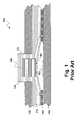
- FIG. 1is a cross-sectional view of an exemplary prior art keyboard
- FIG. 2is a perspective view of an exemplary fuel cell assembly
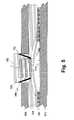
- FIG. 3is a cross-sectional view of a keyboard having a fuel cell membrane inserted therein;
- FIG. 4is a perspective view of a fuel cell membrane as used in FIG. 3 ;
- FIG. 5is a cross-sectional view of an alternative embodiment of a keyboard in which a fuel cell membrane forms part of the printed circuit board;
- FIG. 6is a perspective view of the combination fuel cell membrane and printed circuit board of FIG. 5 ;
- FIG. 7is an exploded view of a mobile device having the fuel cell membrane of FIG. 4 ;
- FIG. 8is an exploded view of a mobile device utilizing a combination printed circuit board and fuel cell membrane.
- FIG. 9is a block diagram of an exemplary mobile device apt to be used with the present disclosure.
- the present disclosureprovides a mobile device comprising: a keyboard; a printed circuit board having at least one contact responsive to the keyboard; and a fuel cell assembly having: a fuel cell located between the keyboard and the printed circuit board, said fuel cell having a membrane and at least one aperture corresponding with the at least one contact; a tank adapted to store a fuel for the fuel cell; and piping connecting the tank with the fuel cell membrane, wherein the fuel cell ventilates through the keyboard.
- the present disclosurefurther provides a mobile device comprising: a keyboard; and a fuel cell assembly having: a fuel cell forming a printed circuit board for the mobile device, the fuel cell having a membrane and at least one contact responsive to the keyboard; a tank adapted to store a fuel for the fuel cell; and piping connecting the tank with the fuel cell membrane, wherein the fuel cell ventilates through the keyboard.
- FIG. 1shows an exemplary cutaway section of a keyboard 100 .
- Keyboard 100includes a key web 110 containing a plurality of keys. As an example, key 120 is shown. Key web 110 fits under device housing section 130 , which includes apertures 132 to accommodate a key 120 .
- Dome actuators 142are resiliently biased to push a plunger 150 within key 120 into an upright position.
- the resiliencycan be accomplished within key web 110 itself.
- Dome actuator panel 140is over a printed circuit board (PCB) 160 .
- PCB 160contains a plurality of contacts 162 .
- a userpresses key 120 , which forces plunger 150 into actuator dome 142 .
- Actuator dome 142flexes and makes contact with contact 162 , completing a circuit and causing a key stroke to be registered on the device.
- the present disclosureis not meant to be limited by the number or orientation of keys 120 within a device housing section 130 , and a plurality of such configurations would be known to those in the art.
- key web 120could be resilient enough to provide elasticity to return key 120 into its upright position.
- plunger 150could be formed of a conducting material that would close a connection on contact 162 thereby causing the key stroke to be registered.
- keypads or keyboardswould also be known to those in the art and the present disclosure is not made to be limited to a particular type of keyboard actuation.
- a fuel cell assemblymay be added to a mobile device in order to provide for an extended energy life.
- the use of a fuel cell assemblycould extend the power provision over a conventional battery and thus could be desirable for mobile devices.
- Fuel cell assembliesare known in the art, and one example of a fuel cell assembly is illustrated with respect to FIG. 2 .
- the fuel cell assembly of FIG. 2is not to be limiting however and other fuel cells would be applicable to the present disclosure.
- a fuel cell assemblyincludes both a fuel cell and the apparatus allowing a fuel cell to work, including but not limited to the tank and associated piping.
- Fuel cell assembly 200 of FIG. 2includes a variety of layers.
- a fuel cell 205consists of a polymer electrode membrane 210 that is displaced between an anode 220 and a cathode 230 .
- the polymer electrolyte membrane 210is provided to only allow the exchange of protons between anode 220 and cathode 230 but does not allow electrons to flow in this way. This causes the electrons to flow through a circuit 240 thereby powering the circuit.
- Other layersinclude backing layers 222 and 232 for anode 220 and cathode 230 respectfully.
- a fuelsuch as a hydrogen gas flows from a storage tank 260 through channels 262 and back into storage tank 260 for any unused fuel.
- an oxidant 270flows through channels 272 and is adapted to react with the fuel to form heat and water.
- the only waste product in this caseis either liquid or vapour.
- the anodeis the negative post of fuel cells and has several jobs. It conducts electrons that are freed from the hydrogen molecules to be used in circuit 240 .
- the cathodeis the positive side of the fuel cell and has the job of connecting the electrons back from the external circuit to catalyst.
- the polymer electrolyte membrane 210is a specially treated material that conducts only positively charged ions. Thus, the membrane blocks electrons and causes them to bypass the membrane through circuit 240 .
- a polymer exchange fuel cellcould be utilized instead of a proton exchange membrane fuel cell. This is similar in that it has an anode and cathode separated by a proton exchange membrane. In this case a catalyst also exists between the proton exchange membrane and the cathode to facilitate the reaction of the oxygen and hydrogen. In one embodiment it is made of platinum nanoparticles that are very thinly coated onto carbon paper or cloth. The catalyst is rough and porous so that a large surface area on the platinum could be exposed to the hydrogen or oxygen.
- the abovetherefore provides for a system having a fuel cell portion such as fuel cell 205 , which includes a membrane, and a fuel storage portion such as storage tank 260 . Further a circuit portion such as circuit 240 can be driven from the fuel cell assembly 200 .
- a printed circuit board 160includes a switch 161 having a contact 162 thereon.
- a dome actuator 142is adapted to be depressed and make contact and make contact 162 thereby completing the circuit and causing a keystroke to be registered. Dome actuator 142 sits on dome actuator panel 140 .
- a fuel cell 310is added above dome actuator panel 140 .
- Such a fuel cellcould be fuel cell 205 from FIG. 2 .
- a key web 320sits above fuel cell 310 and includes a series of keys 322 protruding there from.
- a device housing section 130includes a series of apertures 132 therein to allow a key 322 to protrude there from.
- a plunger 330extends from key 322 to make contact with dome actuator 142 .
- Vents 340are provided within key 322 to allow heat and vapour to escape from fuel cell 310 through the keypad of the mobile device.
- plunger 330could be made longer than plunger 150 of FIG. 1 in order to allow it to proceed through fuel cell 310 to actuate the dome actuator 142 .
- a first advantageis that the key becomes a porous grill and with the fuel cell underneath allows for more natural venting. This also provides for airflow under the fuel cell as well. In addition, by placing the fuel cell under the keypad, minimal additional space is required to accommodate the fuel cell.
- FIG. 3also allows for more heat dissipation since the keypad is on top of the unit and not underneath it. Therefore heat will rise through the keypad when the device is left in a cradle or laid on its back.
- a further advantageis that on the backside of the mobile device, dirt will tend to build up since this is often the side that is placed down. This tends to clog any grate that is on the back of the mobile device.
- dome actuator 142may not be included and instead plunger 330 would be conductive, thus triggering the switch when in contact with contact 162 .
- key web 320needs to be resilient enough to bring the key back into its upright position once it is released but the remainder of the process works in the same way.
- FIG. 4shows a fuel cell 410 having a membrane, which in one embodiment could be the same as fuel cell 310 from FIG. 3 .
- a series of holes 420are provided in fuel cell 410 to allow plungers such as plunger 330 to proceed through and to make contact with contact 162 either through a dome actuator or directly.
- the fuel cell membranemay have circuits printed on it, and thus the fuel cell itself becomes the printed circuit board.
- FIG. 5shows a fuel cell 510 in which circuits are printed thereon.
- a contact 512is printed onto the fuel cell 510 .
- a dome actuator panel 140contains a plurality dome actuators 142 which are adapted to make contact with contact 512 .
- a key web 320forming a portion of the keyboard of a device, sits above dome actuator panel 140 and includes a plurality of keys 322 therein. Keys 322 are adapted to protrude through an aperture 132 of device housing section 130 and a plunger 150 is adapted to depress dome actuator 142 into contact 512 .
- Key web 320includes a series of ventilation holes 340 to allow heat and water vapour to escape from fuel cell 510 , thereby providing the advantages of the present disclosure.
- the ventilation holesfacilitate heat and water vapour dissipation, which are by-products of the fuel cell.
- a device when placed on a surfaceis usually placed in its back.
- the ventilation holes 340 in the key web, and thereby in the upward facing keyboardthe holes will not be plugged as easily with dirt as they would be if located in the back of a mobile device. Since heat rises, heat dissipation is further enhanced in the configuration of FIG. 3 .
- a further advantage of ventilation through a keyboardis the greater surface area for potential ventilation.
- devices that ventilate through a hole in a back or side of the devicehave one location for water vapour to escape, leading to more condensation and less heat and vapour dissipation.
- the keyboard of a devicetypically has a key web with multiple keys. If each has ventilation holes 340 , the ventilation of the device is spread over a larger area, making ventilation more efficient and potentially reducing condensation that could affect a user of the device.
- Fuel cell 510includes contacts 512 . As seen from FIG. 6 , a plurality of contacts 512 are configured on fuel cell 510 .
- the configuration of the keyswill be determined by the mobile device and the present disclosure is not meant to be limited to any particular configuration of contacts 512 .
- venting of water vapour and heatcan be done around actuators 142 or can be done through ports in key web 320 and dome actuator panel 140 .
- Lightcan be projected through the fuel cell 510 , 410 , 310 or 205 either by introducing “light pipes” in the membrane to allow light to filter through, or by forming the fuel cell such that it is transparent enough to allow light to proceed through the membrane, thereby allowing for the illumination of keys.
- FIGS. 7 and 8An exemplary device structure is shown in FIGS. 7 and 8 . This structure is only an example and other configurations are possible.
- a device 700includes a printed circuit board 160 . Most of the internal components of the mobile communication device are preferably mounted on the PCB 160 .
- the keyboardis preferably formed with a key web 320 over a plurality of contacts 162 on the PCB 160 .
- the key web 320 and a plurality of contacts 162are configured such that each key in the key web 320 contacts and operates one of the contacts 162 when the key is depressed.
- Other configurationsmight also be implemented as indicated above. Further, these implementations may include the number of contacts 162 being less than the number of keys 322 , or the number of contacts 162 may be greater then the number of keys 322 on key web 320 .
- Key web 320 and contacts 162are also positioned such that apertures 132 on device housing section 130 are at least partially exposed to keys 322 . Portions of the key web 320 are exposed by the apertures 132 to provide key surfaces that may be depressed by a user to provide data input to the device 700 . Such data input may, for example, be used to generate data communications on the device 700 .
- a fuel cell 410 having a series of holes 412 thereinis adapted to be placed between the key web 320 and contacts 162 , whereby holes 412 align with contacts 162 to allow a contact from a plunger (not shown) of key web 322 to make contact with contact 162 .
- a display 710is preferably mounted on the PCB 160 as shown in FIG. 7 .
- an aperture 722 in the housing section 130at least partially exposes the display 710 .
- the aperture 722 in the device housing section 130 and the display 710 on PCB 160may be positioned such that a viewing area of the display 710 is exposed.
- the frame and other components associated with the display 710are preferably hidden from view when the first and second device housing sections 130 and 720 are coupled together.
- a speaker 730is preferably mounted at or near the top of PCB 160 .
- One or more apertures 732are positioned to or at least partially expose the speaker 730 when the device housing portions 130 and 720 are coupled together.
- a microphone 740is mounted in the second device housing section 720 .
- the microphone 740is at least partially exposed by an aperture 742 in the second device housing section 720 , and coupled to the PCB and other device components. Audio and/or voice inputs to the microphone 740 may be used, for example, to generate voice communications.
- an aperture(not shown) is provided in the first device housing section 132 at least partially expose the microphone 740 .
- the microphone 740may alternatively be mounted to the device housing section 130 or PCB 160 .
- Device housing sections 130 and 720may include further apertures to expose or partially expose other device components.
- apertures 750 , 752 and 754are configured to partially expose the auxiliary input/output (I/O) devices.
- An aperture 756is similarly positioned in device housing section 720 to at least partially expose and auxiliary input/output device.
- An aperture 760is adapted to accommodate the fuel tank such as fuel tank 260 from FIG. 2 .
- the configuration of FIG. 7provides the further advantage that heat is absorbed by tank 260 , and thus placing it under PCB 160 is beneficial.
- fuel tank 260can be connected to fuel cell 410 through the use of micro-valves and piping to provide for the flow of the fuel through fuel cell 410 .
- Various affixing portionssuch as 770 and 772 may be adapted to receive screws to hold PCB 160 and casing 130 and casing 720 together.
- FIG. 8this figure utilizes similar reference numerals to those in FIG. 7 for mobile device 800 , with the exception of PCB 160 from FIG. 7 being replaced by fuel cell 510 and contacts 162 being replaced by contacts 512 . In this way, the functionality of PCB 160 is replaced by a fuel cell which can act as a printed circuit board.
- mobile device 900can be powered by a fuel cell assembly, as illustrated in FIG. 2 .
- Mobile device 900is preferably a two-way wireless communication device having at least voice and data communication capabilities. Mobile device 900 preferably has the capability to communicate with other computer systems on the Internet. Depending on the exact functionality provided, the wireless device may be referred to as a data messaging device, a two-way pager, a wireless e-mail device, a cellular telephone with data messaging capabilities, a wireless Internet appliance, or a data communication device, as examples.
- mobile device 900When mobile device 900 is enabled for two-way communication, it will incorporate a communication subsystem 911 , including both a receiver 912 and a transmitter 914 , as well as associated components such as one or more, preferably embedded or internal, antenna elements 916 and 918 , local oscillators (LOs) 913 , and a processing module such as a digital signal processor (DSP) 920 .
- a communication subsystem 911including both a receiver 912 and a transmitter 914 , as well as associated components such as one or more, preferably embedded or internal, antenna elements 916 and 918 , local oscillators (LOs) 913 , and a processing module such as a digital signal processor (DSP) 920 .
- DSPdigital signal processor
- Mobile network 900could be any network including but not limited to: the global system for mobile communications (GSM), general packet radio service (GPRS), code division multiple access (CDMA), universal mobile telecommunications system (UMTS), wideband code divisional multiple access (WCDMA) among others. These technologies allow the use of voice, data or both at the same time.
- GSMglobal system for mobile communications
- GPRSgeneral packet radio service
- CDMAcode division multiple access
- UMTSuniversal mobile telecommunications system
- WCDMAwideband code divisional multiple access
- Network access requirementswill also vary depending upon the type of network 919 .
- network accessis associated with a subscriber or user of mobile device 900 .
- a GPRS mobile devicetherefore requires a subscriber identity module (SIM) card in order to operate on a GPRS network.
- SIMsubscriber identity module
- UMTS and LTEa USIM or SIM module is required.
- CDMAa RUIM card or module is required.
- the UIM interface 944is normally similar to a card-slot into which a card can be inserted and ejected like a diskette or PCMCIA card.
- the UIM cardcan have approximately 64K of memory and hold many key configuration 951 , and other information 953 such as identification, and subscriber related information.
- mobile device 900may send and receive communication signals over the network 919 .
- Signals received by antenna 916 through communication network 919are input to receiver 912 , which may perform such common receiver functions as signal amplification, frequency down conversion, filtering, channel selection and the like, and in the example system shown in FIG. 9 , analog to digital (A/D) conversion.
- A/D conversion of a received signalallows more complex communication functions such as demodulation and decoding to be performed in the DSP 920 .
- signals to be transmittedare processed, including modulation and encoding for example, by DSP 920 and input to transmitter 914 for digital to analog conversion, frequency up conversion, filtering, amplification and transmission over the communication network 919 via antenna 918 .
- DSP 920not only processes communication signals, but also provides for receiver and transmitter control. For example, the gains applied to communication signals in receiver 912 and transmitter 914 may be adaptively controlled through automatic gain control algorithms implemented in DSP 920 .
- Network 919may further communicate with multiple systems, including a server 960 and other elements (not shown).
- network 919may communicate with both an enterprise system and a web client system in order to accommodate various clients with various service levels.
- Mobile device 900preferably includes a microprocessor 938 which controls the overall operation of the device. Communication functions, including at least data communications, are performed through communication subsystem 911 . Microprocessor 938 also interacts with further device subsystems such as the display 922 , flash memory 924 , random access memory (RAM) 926 , auxiliary input/output (I/O) subsystems 928 , serial port 930 , keyboard 932 , speaker 934 , microphone 936 , a short-range communications subsystem 940 and any other device subsystems generally designated as 942 .
- a microprocessor 938which controls the overall operation of the device. Communication functions, including at least data communications, are performed through communication subsystem 911 . Microprocessor 938 also interacts with further device subsystems such as the display 922 , flash memory 924 , random access memory (RAM) 926 , auxiliary input/output (I/O) subsystems 928 , serial port 930 , keyboard 932 , speaker 934 , microphone 936
- Some of the subsystems shown in FIG. 9perform communication-related functions, whereas other subsystems may provide “resident” or on-device functions.
- some subsystemssuch as keyboard 932 and display 922 , for example, may be used for both communication-related functions, such as entering a text message for transmission over a communication network, and device-resident functions such as a calculator or task list.
- Operating system software used by the microprocessor 938is preferably stored in a persistent store such as flash memory 924 , which may instead be a read-only memory (ROM) or similar storage element (not shown).
- ROMread-only memory
- Those skilled in the artwill appreciate that the operating system, specific device applications, or parts thereof, may be temporarily loaded into a volatile memory such as RAM 926 .
- Received communication signalsmay also be stored in RAM 926 .
- a unique identifieris also preferably stored in read-only memory.
- flash memory 924can be segregated into different areas for both computer programs 958 and program data storage 950 , 952 , 954 and 956 . These different storage types indicate that each program can allocate a portion of flash memory 924 for their own data storage requirements.
- Microprocessor 938in addition to its operating system functions, preferably enables execution of software applications on the mobile device. A predetermined set of applications that control basic operations, including at least data and voice communication applications for example, will normally be installed on mobile device 900 during manufacturing.
- a preferred software applicationmay be a personal information manager (PIM) application having the ability to organize and manage data items relating to the user of the mobile device such as, but not limited to, e-mail, calendar events, voice mails, appointments, and task items.
- PIMpersonal information manager
- PIM applicationwould preferably have the ability to send and receive data items, via the wireless network 919 .
- the PIM data itemsare seamlessly integrated, synchronized and updated, via the wireless network 919 , with the mobile device user's corresponding data items stored or associated with a host computer system.
- Further applicationsmay also be loaded onto the mobile device 900 through the network 919 , an auxiliary I/O subsystem 928 , serial port 930 , short-range communications subsystem 940 or any other suitable subsystem 942 , and installed by a user in the RAM 926 or preferably a non-volatile store (not shown) for execution by the microprocessor 938 .
- secure communication applicationsmay enable electronic commerce functions and other such financial transactions to be performed using the mobile device 900 . These applications will however, according to the above, in many cases need to be approved by a carrier.
- a received signalsuch as a text message or web page download will be processed by the communication subsystem 911 and input to the microprocessor 938 , which preferably further processes the received signal for output to the display 922 , or alternatively to an auxiliary I/O device 928 .
- a user of mobile device 900may also compose data items such as email messages for example, using the keyboard 932 , which is preferably a complete alphanumeric keyboard or telephone-type keypad, in conjunction with the display 922 and possibly an auxiliary I/O device 928 . Such composed items may then be transmitted over a communication network through the communication subsystem 911 .
- mobile device 900For voice communications, overall operation of mobile device 900 is similar, except that received signals would preferably be output to a speaker 934 and signals for transmission would be generated by a microphone 936 .
- Alternative voice or audio I/O subsystemssuch as a voice message recording subsystem, may also be implemented on mobile device 900 .
- voice or audio signal outputis preferably accomplished primarily through the speaker 934
- display 922may also be used to provide an indication of the identity of a calling party, the duration of a voice call, or other voice call related information for example.
- Serial port 930 in FIG. 9would normally be implemented in a personal digital assistant (PDA)-type mobile device for which synchronization with a user's desktop computer (not shown) may be desirable.
- PDApersonal digital assistant
- Such a port 930would enable a user to set preferences through an external device or software application and would extend the capabilities of mobile device 900 by providing for information or software downloads to mobile device 900 other than through a wireless communication network.
- the alternate download pathmay for example be used to load an encryption key onto the device through a direct and thus reliable and trusted connection to thereby enable secure device communication.
- serial port 930could be used for other communications, and could include as a universal serial bus (USB) port.
- USBuniversal serial bus
- An interfaceis associated with serial port 930 .
- communications subsystems 940such as a short-range communications subsystem, is a further optional component which may provide for communication between mobile device 900 and different systems or devices, which need not necessarily be similar devices.
- the subsystem 940may include an infrared device and associated circuits and components or a BluetoothTM communication module to provide for communication with similarly enabled systems and devices.
Landscapes
- Engineering & Computer Science (AREA)
- Signal Processing (AREA)
- Life Sciences & Earth Sciences (AREA)
- Manufacturing & Machinery (AREA)
- Sustainable Development (AREA)
- Sustainable Energy (AREA)
- Chemical & Material Sciences (AREA)
- Chemical Kinetics & Catalysis (AREA)
- Electrochemistry (AREA)
- General Chemical & Material Sciences (AREA)
- Fuel Cell (AREA)
Abstract
Description
Claims (15)
Priority Applications (3)
| Application Number | Priority Date | Filing Date | Title |
|---|---|---|---|
| US12/394,641US8133621B2 (en) | 2009-02-27 | 2009-02-27 | Location of a fuel cell on a mobile device |
| CA2693882ACA2693882C (en) | 2009-02-27 | 2010-02-22 | Location of a fuel cell on a mobile device |
| US13/365,664US9648151B2 (en) | 2009-02-27 | 2012-02-03 | Location of a fuel cell on a mobile device |
Applications Claiming Priority (1)
| Application Number | Priority Date | Filing Date | Title |
|---|---|---|---|
| US12/394,641US8133621B2 (en) | 2009-02-27 | 2009-02-27 | Location of a fuel cell on a mobile device |
Related Child Applications (1)
| Application Number | Title | Priority Date | Filing Date |
|---|---|---|---|
| US13/365,664ContinuationUS9648151B2 (en) | 2009-02-27 | 2012-02-03 | Location of a fuel cell on a mobile device |
Publications (2)
| Publication Number | Publication Date |
|---|---|
| US20100221617A1 US20100221617A1 (en) | 2010-09-02 |
| US8133621B2true US8133621B2 (en) | 2012-03-13 |
Family
ID=42667285
Family Applications (2)
| Application Number | Title | Priority Date | Filing Date |
|---|---|---|---|
| US12/394,641Active2030-05-16US8133621B2 (en) | 2009-02-27 | 2009-02-27 | Location of a fuel cell on a mobile device |
| US13/365,664Active2030-07-02US9648151B2 (en) | 2009-02-27 | 2012-02-03 | Location of a fuel cell on a mobile device |
Family Applications After (1)
| Application Number | Title | Priority Date | Filing Date |
|---|---|---|---|
| US13/365,664Active2030-07-02US9648151B2 (en) | 2009-02-27 | 2012-02-03 | Location of a fuel cell on a mobile device |
Country Status (1)
| Country | Link |
|---|---|
| US (2) | US8133621B2 (en) |
Cited By (29)
| Publication number | Priority date | Publication date | Assignee | Title |
|---|---|---|---|---|
| US20120099286A1 (en)* | 2010-03-11 | 2012-04-26 | Panasonic Corporation | Electronic apparatus |
| US9554477B1 (en) | 2015-12-18 | 2017-01-24 | International Business Machines Corporation | Tamper-respondent assemblies with enclosure-to-board protection |
| US9560737B2 (en) | 2015-03-04 | 2017-01-31 | International Business Machines Corporation | Electronic package with heat transfer element(s) |
| US9555606B1 (en) | 2015-12-09 | 2017-01-31 | International Business Machines Corporation | Applying pressure to adhesive using CTE mismatch between components |
| US9578764B1 (en) | 2015-09-25 | 2017-02-21 | International Business Machines Corporation | Enclosure with inner tamper-respondent sensor(s) and physical security element(s) |
| US9591776B1 (en) | 2015-09-25 | 2017-03-07 | International Business Machines Corporation | Enclosure with inner tamper-respondent sensor(s) |
| US9858776B1 (en) | 2016-06-28 | 2018-01-02 | International Business Machines Corporation | Tamper-respondent assembly with nonlinearity monitoring |
| US9881880B2 (en) | 2016-05-13 | 2018-01-30 | International Business Machines Corporation | Tamper-proof electronic packages with stressed glass component substrate(s) |
| US9894749B2 (en) | 2015-09-25 | 2018-02-13 | International Business Machines Corporation | Tamper-respondent assemblies with bond protection |
| US9904811B2 (en) | 2016-04-27 | 2018-02-27 | International Business Machines Corporation | Tamper-proof electronic packages with two-phase dielectric fluid |
| US9913389B2 (en) | 2015-12-01 | 2018-03-06 | International Business Corporation Corporation | Tamper-respondent assembly with vent structure |
| US9913370B2 (en) | 2016-05-13 | 2018-03-06 | International Business Machines Corporation | Tamper-proof electronic packages formed with stressed glass |
| US9911012B2 (en) | 2015-09-25 | 2018-03-06 | International Business Machines Corporation | Overlapping, discrete tamper-respondent sensors |
| US9916744B2 (en) | 2016-02-25 | 2018-03-13 | International Business Machines Corporation | Multi-layer stack with embedded tamper-detect protection |
| US9924591B2 (en) | 2015-09-25 | 2018-03-20 | International Business Machines Corporation | Tamper-respondent assemblies |
| US9978231B2 (en) | 2015-10-21 | 2018-05-22 | International Business Machines Corporation | Tamper-respondent assembly with protective wrap(s) over tamper-respondent sensor(s) |
| US9999124B2 (en) | 2016-11-02 | 2018-06-12 | International Business Machines Corporation | Tamper-respondent assemblies with trace regions of increased susceptibility to breaking |
| US10098235B2 (en) | 2015-09-25 | 2018-10-09 | International Business Machines Corporation | Tamper-respondent assemblies with region(s) of increased susceptibility to damage |
| US10136519B2 (en) | 2015-10-19 | 2018-11-20 | International Business Machines Corporation | Circuit layouts of tamper-respondent sensors |
| US10172239B2 (en) | 2015-09-25 | 2019-01-01 | International Business Machines Corporation | Tamper-respondent sensors with formed flexible layer(s) |
| US10168185B2 (en) | 2015-09-25 | 2019-01-01 | International Business Machines Corporation | Circuit boards and electronic packages with embedded tamper-respondent sensor |
| US10271424B2 (en) | 2016-09-26 | 2019-04-23 | International Business Machines Corporation | Tamper-respondent assemblies with in situ vent structure(s) |
| US10299372B2 (en) | 2016-09-26 | 2019-05-21 | International Business Machines Corporation | Vented tamper-respondent assemblies |
| US10306753B1 (en) | 2018-02-22 | 2019-05-28 | International Business Machines Corporation | Enclosure-to-board interface with tamper-detect circuit(s) |
| US10321589B2 (en) | 2016-09-19 | 2019-06-11 | International Business Machines Corporation | Tamper-respondent assembly with sensor connection adapter |
| US10327329B2 (en) | 2017-02-13 | 2019-06-18 | International Business Machines Corporation | Tamper-respondent assembly with flexible tamper-detect sensor(s) overlying in-situ-formed tamper-detect sensor |
| US10327343B2 (en) | 2015-12-09 | 2019-06-18 | International Business Machines Corporation | Applying pressure to adhesive using CTE mismatch between components |
| US10426037B2 (en) | 2015-07-15 | 2019-09-24 | International Business Machines Corporation | Circuitized structure with 3-dimensional configuration |
| US11122682B2 (en) | 2018-04-04 | 2021-09-14 | International Business Machines Corporation | Tamper-respondent sensors with liquid crystal polymer layers |
Families Citing this family (2)
| Publication number | Priority date | Publication date | Assignee | Title |
|---|---|---|---|---|
| US20110134065A1 (en)* | 2003-01-15 | 2011-06-09 | Asustek Computer Inc. | Notebook Computer with Hidden Touch Sensitive Unit |
| US8184833B2 (en)* | 2007-12-14 | 2012-05-22 | Sony Ericsson Mobile Communications Ab | Electrostatic speaker arrangement for a mobile device |
Citations (9)
| Publication number | Priority date | Publication date | Assignee | Title |
|---|---|---|---|---|
| JP2000148307A (en) | 1998-11-10 | 2000-05-26 | Sony Corp | Keyboard |
| WO2000035032A1 (en) | 1998-12-10 | 2000-06-15 | Hockaday Robert G | Micro-fuel cell power devices |
| US20030142467A1 (en)* | 2002-01-29 | 2003-07-31 | Shogo Hachiya | Portable information device capable of using fuel cell |
| US20050053808A1 (en) | 2003-09-08 | 2005-03-10 | Wistron Corporation | Method and system for improving efficiency of fuel cell in portable devices |
| EP1672464A2 (en) | 2004-12-15 | 2006-06-21 | NEC Corporation | Mobile terminal device and method for radiating heat therefrom |
| US20070015551A1 (en) | 2005-07-12 | 2007-01-18 | Yoshihiro Iwama | Portable terminal device |
| WO2007037422A1 (en) | 2005-09-30 | 2007-04-05 | Kyocera Corporation | Fuel cell and electronic device comprising such fuel cell |
| US20070196715A1 (en) | 2006-02-21 | 2007-08-23 | Hsi-Ming Shu | Fuel cell device adapted to slim-type CD-ROM drive |
| WO2007117212A2 (en) | 2006-04-11 | 2007-10-18 | Myfc Ab | Polymer electrolyte electrochemical device |
Family Cites Families (7)
| Publication number | Priority date | Publication date | Assignee | Title |
|---|---|---|---|---|
| US5801345A (en)* | 1996-06-21 | 1998-09-01 | Acuson Corporation | Keyboard assembly incorporating multiple lighting modes for improved user feedback |
| GB9718232D0 (en)* | 1997-08-29 | 1997-11-05 | Ncr Int Inc | Keyboard |
| DE69932304T2 (en)* | 1998-11-09 | 2007-12-06 | Ballard Power Systems Inc., Burnaby | Electrical contact device for a fuel cell |
| US7335843B2 (en)* | 1998-11-13 | 2008-02-26 | Firefly International, Inc. | Computer keyboard backlighting |
| JP2004134355A (en)* | 2002-08-16 | 2004-04-30 | Fuji Photo Film Co Ltd | Fuel cell, electronic device, portable terminal and camera |
| GB0304709D0 (en)* | 2003-03-01 | 2003-04-02 | Univ Aberdeen | Photo-catalytic fuel cell |
| US20070072042A1 (en)* | 2005-09-23 | 2007-03-29 | Duhane Lam | Portable fuel cell power source |
- 2009
- 2009-02-27USUS12/394,641patent/US8133621B2/enactiveActive
- 2012
- 2012-02-03USUS13/365,664patent/US9648151B2/enactiveActive
Patent Citations (9)
| Publication number | Priority date | Publication date | Assignee | Title |
|---|---|---|---|---|
| JP2000148307A (en) | 1998-11-10 | 2000-05-26 | Sony Corp | Keyboard |
| WO2000035032A1 (en) | 1998-12-10 | 2000-06-15 | Hockaday Robert G | Micro-fuel cell power devices |
| US20030142467A1 (en)* | 2002-01-29 | 2003-07-31 | Shogo Hachiya | Portable information device capable of using fuel cell |
| US20050053808A1 (en) | 2003-09-08 | 2005-03-10 | Wistron Corporation | Method and system for improving efficiency of fuel cell in portable devices |
| EP1672464A2 (en) | 2004-12-15 | 2006-06-21 | NEC Corporation | Mobile terminal device and method for radiating heat therefrom |
| US20070015551A1 (en) | 2005-07-12 | 2007-01-18 | Yoshihiro Iwama | Portable terminal device |
| WO2007037422A1 (en) | 2005-09-30 | 2007-04-05 | Kyocera Corporation | Fuel cell and electronic device comprising such fuel cell |
| US20070196715A1 (en) | 2006-02-21 | 2007-08-23 | Hsi-Ming Shu | Fuel cell device adapted to slim-type CD-ROM drive |
| WO2007117212A2 (en) | 2006-04-11 | 2007-10-18 | Myfc Ab | Polymer electrolyte electrochemical device |
Non-Patent Citations (1)
| Title |
|---|
| EP 09154039, Search Report dated Jun. 26, 2009. |
Cited By (65)
| Publication number | Priority date | Publication date | Assignee | Title |
|---|---|---|---|---|
| US20120099286A1 (en)* | 2010-03-11 | 2012-04-26 | Panasonic Corporation | Electronic apparatus |
| US9560737B2 (en) | 2015-03-04 | 2017-01-31 | International Business Machines Corporation | Electronic package with heat transfer element(s) |
| US10237964B2 (en) | 2015-03-04 | 2019-03-19 | International Business Machines Corporation | Manufacturing electronic package with heat transfer element(s) |
| US10524362B2 (en) | 2015-07-15 | 2019-12-31 | International Business Machines Corporation | Circuitized structure with 3-dimensional configuration |
| US10426037B2 (en) | 2015-07-15 | 2019-09-24 | International Business Machines Corporation | Circuitized structure with 3-dimensional configuration |
| US10178818B2 (en) | 2015-09-25 | 2019-01-08 | International Business Machines Corporation | Enclosure with inner tamper-respondent sensor(s) and physical security element(s) |
| US10334722B2 (en) | 2015-09-25 | 2019-06-25 | International Business Machines Corporation | Tamper-respondent assemblies |
| US9717154B2 (en) | 2015-09-25 | 2017-07-25 | International Business Machines Corporation | Enclosure with inner tamper-respondent sensor(s) |
| US10685146B2 (en) | 2015-09-25 | 2020-06-16 | International Business Machines Corporation | Overlapping, discrete tamper-respondent sensors |
| US10175064B2 (en) | 2015-09-25 | 2019-01-08 | International Business Machines Corporation | Circuit boards and electronic packages with embedded tamper-respondent sensor |
| US10624202B2 (en) | 2015-09-25 | 2020-04-14 | International Business Machines Corporation | Tamper-respondent assemblies with bond protection |
| US9894749B2 (en) | 2015-09-25 | 2018-02-13 | International Business Machines Corporation | Tamper-respondent assemblies with bond protection |
| US10271434B2 (en) | 2015-09-25 | 2019-04-23 | International Business Machines Corporation | Method of fabricating a tamper-respondent assembly with region(s) of increased susceptibility to damage |
| US9591776B1 (en) | 2015-09-25 | 2017-03-07 | International Business Machines Corporation | Enclosure with inner tamper-respondent sensor(s) |
| US10395067B2 (en) | 2015-09-25 | 2019-08-27 | International Business Machines Corporation | Method of fabricating a tamper-respondent sensor assembly |
| US9913416B2 (en) | 2015-09-25 | 2018-03-06 | International Business Machines Corporation | Enclosure with inner tamper-respondent sensor(s) and physical security element(s) |
| US9911012B2 (en) | 2015-09-25 | 2018-03-06 | International Business Machines Corporation | Overlapping, discrete tamper-respondent sensors |
| US9913362B2 (en) | 2015-09-25 | 2018-03-06 | International Business Machines Corporation | Tamper-respondent assemblies with bond protection |
| US10378924B2 (en) | 2015-09-25 | 2019-08-13 | International Business Machines Corporation | Circuit boards and electronic packages with embedded tamper-respondent sensor |
| US9924591B2 (en) | 2015-09-25 | 2018-03-20 | International Business Machines Corporation | Tamper-respondent assemblies |
| US9936573B2 (en) | 2015-09-25 | 2018-04-03 | International Business Machines Corporation | Tamper-respondent assemblies |
| US10168185B2 (en) | 2015-09-25 | 2019-01-01 | International Business Machines Corporation | Circuit boards and electronic packages with embedded tamper-respondent sensor |
| US10378925B2 (en) | 2015-09-25 | 2019-08-13 | International Business Machines Corporation | Circuit boards and electronic packages with embedded tamper-respondent sensor |
| US10098235B2 (en) | 2015-09-25 | 2018-10-09 | International Business Machines Corporation | Tamper-respondent assemblies with region(s) of increased susceptibility to damage |
| US10331915B2 (en) | 2015-09-25 | 2019-06-25 | International Business Machines Corporation | Overlapping, discrete tamper-respondent sensors |
| US10257939B2 (en) | 2015-09-25 | 2019-04-09 | International Business Machines Corporation | Method of fabricating tamper-respondent sensor |
| US10264665B2 (en) | 2015-09-25 | 2019-04-16 | International Business Machines Corporation | Tamper-respondent assemblies with bond protection |
| US9578764B1 (en) | 2015-09-25 | 2017-02-21 | International Business Machines Corporation | Enclosure with inner tamper-respondent sensor(s) and physical security element(s) |
| US10172239B2 (en) | 2015-09-25 | 2019-01-01 | International Business Machines Corporation | Tamper-respondent sensors with formed flexible layer(s) |
| US10143090B2 (en) | 2015-10-19 | 2018-11-27 | International Business Machines Corporation | Circuit layouts of tamper-respondent sensors |
| US10136519B2 (en) | 2015-10-19 | 2018-11-20 | International Business Machines Corporation | Circuit layouts of tamper-respondent sensors |
| US9978231B2 (en) | 2015-10-21 | 2018-05-22 | International Business Machines Corporation | Tamper-respondent assembly with protective wrap(s) over tamper-respondent sensor(s) |
| US9913389B2 (en) | 2015-12-01 | 2018-03-06 | International Business Corporation Corporation | Tamper-respondent assembly with vent structure |
| US10251288B2 (en) | 2015-12-01 | 2019-04-02 | International Business Machines Corporation | Tamper-respondent assembly with vent structure |
| US10327343B2 (en) | 2015-12-09 | 2019-06-18 | International Business Machines Corporation | Applying pressure to adhesive using CTE mismatch between components |
| US9555606B1 (en) | 2015-12-09 | 2017-01-31 | International Business Machines Corporation | Applying pressure to adhesive using CTE mismatch between components |
| US9661747B1 (en) | 2015-12-18 | 2017-05-23 | International Business Machines Corporation | Tamper-respondent assemblies with enclosure-to-board protection |
| US9554477B1 (en) | 2015-12-18 | 2017-01-24 | International Business Machines Corporation | Tamper-respondent assemblies with enclosure-to-board protection |
| US9877383B2 (en) | 2015-12-18 | 2018-01-23 | International Business Machines Corporation | Tamper-respondent assemblies with enclosure-to-board protection |
| US10172232B2 (en) | 2015-12-18 | 2019-01-01 | International Business Machines Corporation | Tamper-respondent assemblies with enclosure-to-board protection |
| US10169968B1 (en) | 2016-02-25 | 2019-01-01 | International Business Machines Corporation | Multi-layer stack with embedded tamper-detect protection |
| US9916744B2 (en) | 2016-02-25 | 2018-03-13 | International Business Machines Corporation | Multi-layer stack with embedded tamper-detect protection |
| US10217336B2 (en) | 2016-02-25 | 2019-02-26 | International Business Machines Corporation | Multi-layer stack with embedded tamper-detect protection |
| US10115275B2 (en) | 2016-02-25 | 2018-10-30 | International Business Machines Corporation | Multi-layer stack with embedded tamper-detect protection |
| US10169967B1 (en) | 2016-02-25 | 2019-01-01 | International Business Machines Corporation | Multi-layer stack with embedded tamper-detect protection |
| US9904811B2 (en) | 2016-04-27 | 2018-02-27 | International Business Machines Corporation | Tamper-proof electronic packages with two-phase dielectric fluid |
| US10169624B2 (en) | 2016-04-27 | 2019-01-01 | International Business Machines Corporation | Tamper-proof electronic packages with two-phase dielectric fluid |
| US10177102B2 (en) | 2016-05-13 | 2019-01-08 | International Business Machines Corporation | Tamper-proof electronic packages with stressed glass component substrate(s) |
| US9913370B2 (en) | 2016-05-13 | 2018-03-06 | International Business Machines Corporation | Tamper-proof electronic packages formed with stressed glass |
| US9881880B2 (en) | 2016-05-13 | 2018-01-30 | International Business Machines Corporation | Tamper-proof electronic packages with stressed glass component substrate(s) |
| US10535618B2 (en) | 2016-05-13 | 2020-01-14 | International Business Machines Corporation | Tamper-proof electronic packages with stressed glass component substrate(s) |
| US10535619B2 (en) | 2016-05-13 | 2020-01-14 | International Business Machines Corporation | Tamper-proof electronic packages with stressed glass component substrate(s) |
| US10257924B2 (en) | 2016-05-13 | 2019-04-09 | International Business Machines Corporation | Tamper-proof electronic packages formed with stressed glass |
| US10242543B2 (en) | 2016-06-28 | 2019-03-26 | International Business Machines Corporation | Tamper-respondent assembly with nonlinearity monitoring |
| US9858776B1 (en) | 2016-06-28 | 2018-01-02 | International Business Machines Corporation | Tamper-respondent assembly with nonlinearity monitoring |
| US10321589B2 (en) | 2016-09-19 | 2019-06-11 | International Business Machines Corporation | Tamper-respondent assembly with sensor connection adapter |
| US10271424B2 (en) | 2016-09-26 | 2019-04-23 | International Business Machines Corporation | Tamper-respondent assemblies with in situ vent structure(s) |
| US10299372B2 (en) | 2016-09-26 | 2019-05-21 | International Business Machines Corporation | Vented tamper-respondent assemblies |
| US10667389B2 (en) | 2016-09-26 | 2020-05-26 | International Business Machines Corporation | Vented tamper-respondent assemblies |
| US9999124B2 (en) | 2016-11-02 | 2018-06-12 | International Business Machines Corporation | Tamper-respondent assemblies with trace regions of increased susceptibility to breaking |
| US10327329B2 (en) | 2017-02-13 | 2019-06-18 | International Business Machines Corporation | Tamper-respondent assembly with flexible tamper-detect sensor(s) overlying in-situ-formed tamper-detect sensor |
| US10531561B2 (en) | 2018-02-22 | 2020-01-07 | International Business Machines Corporation | Enclosure-to-board interface with tamper-detect circuit(s) |
| US10306753B1 (en) | 2018-02-22 | 2019-05-28 | International Business Machines Corporation | Enclosure-to-board interface with tamper-detect circuit(s) |
| US11083082B2 (en) | 2018-02-22 | 2021-08-03 | International Business Machines Corporation | Enclosure-to-board interface with tamper-detect circuit(s) |
| US11122682B2 (en) | 2018-04-04 | 2021-09-14 | International Business Machines Corporation | Tamper-respondent sensors with liquid crystal polymer layers |
Also Published As
| Publication number | Publication date |
|---|---|
| US20120135277A1 (en) | 2012-05-31 |
| US20100221617A1 (en) | 2010-09-02 |
| US9648151B2 (en) | 2017-05-09 |
Similar Documents
| Publication | Publication Date | Title |
|---|---|---|
| US8133621B2 (en) | Location of a fuel cell on a mobile device | |
| EP2175465B1 (en) | Sealed dome switch for mobile electronic device | |
| US20140202839A1 (en) | Key assembly for a handheld electronic device having a one-piece keycap | |
| KR101284946B1 (en) | Electrochemical device | |
| US20070275753A1 (en) | Dual-mode keypad for a mobile device | |
| EP1742282A4 (en) | ELECTRODE-MEMBRANE ASSEMBLY FOR FUEL CELL AND FUEL CELL USING THE SAME | |
| US7615303B2 (en) | Direct methanol fuel cell and portable computer having the same | |
| US20110268995A1 (en) | Fuel cell storing structure and electronic apparatus | |
| CA2693882C (en) | Location of a fuel cell on a mobile device | |
| EP2224525B1 (en) | Location of a fuel cell on a mobile device | |
| US20120000759A1 (en) | Deflection web for a keypad assembly | |
| US7014929B2 (en) | Fuel cell | |
| US8057954B2 (en) | Membrane-electrode assembly including guard gasket | |
| EP2226822B1 (en) | A key assembly for a handheld electronic device having a one-piece keycap | |
| US8053132B2 (en) | Cathode end plate and breathable fuel cell stack using the same | |
| WO2003092092A3 (en) | Fuel cell base element that limits the methanol passing through the electrolyte | |
| US8557453B2 (en) | Fuel cell system having water recovering and circulating structure | |
| JP3114148U (en) | Detachable fuel cell and power supply system | |
| EP1598891A2 (en) | Fuel cell | |
| JP5523341B2 (en) | Fuel cell protection device | |
| JP2006520995A (en) | Electrochemical energy sources and electronic devices incorporating such energy sources | |
| US20220271314A1 (en) | Fuel cell | |
| EP1596456A2 (en) | Fuel cell | |
| KR20070072988A (en) | Membrane-electrode assembly and fuel cell comprising same | |
| JP2007179900A (en) | Fuel cell system and fuel cell laminate |
Legal Events
| Date | Code | Title | Description |
|---|---|---|---|
| AS | Assignment | Owner name:RESEARCH IN MOTION LIMITED, CANADA Free format text:ASSIGNMENT OF ASSIGNORS INTEREST;ASSIGNORS:WORMALD, CHRIS;REDDY, RAYMOND;WINGER, LYALL KENNETH;SIGNING DATES FROM 20090319 TO 20090514;REEL/FRAME:022687/0861 | |
| STCF | Information on status: patent grant | Free format text:PATENTED CASE | |
| FPAY | Fee payment | Year of fee payment:4 | |
| AS | Assignment | Owner name:BLACKBERRY LIMITED, ONTARIO Free format text:CHANGE OF NAME;ASSIGNOR:RESEARCH IN MOTION LIMITED;REEL/FRAME:037893/0239 Effective date:20130709 | |
| MAFP | Maintenance fee payment | Free format text:PAYMENT OF MAINTENANCE FEE, 8TH YEAR, LARGE ENTITY (ORIGINAL EVENT CODE: M1552); ENTITY STATUS OF PATENT OWNER: LARGE ENTITY Year of fee payment:8 | |
| AS | Assignment | Owner name:MALIKIE INNOVATIONS LIMITED, IRELAND Free format text:ASSIGNMENT OF ASSIGNORS INTEREST;ASSIGNOR:BLACKBERRY LIMITED;REEL/FRAME:064104/0103 Effective date:20230511 | |
| AS | Assignment | Owner name:MALIKIE INNOVATIONS LIMITED, IRELAND Free format text:NUNC PRO TUNC ASSIGNMENT;ASSIGNOR:BLACKBERRY LIMITED;REEL/FRAME:064270/0001 Effective date:20230511 | |
| MAFP | Maintenance fee payment | Free format text:PAYMENT OF MAINTENANCE FEE, 12TH YEAR, LARGE ENTITY (ORIGINAL EVENT CODE: M1553); ENTITY STATUS OF PATENT OWNER: LARGE ENTITY Year of fee payment:12 |