US8133266B2 - Expandable tip delivery system and method - Google Patents
Expandable tip delivery system and methodDownload PDFInfo
- Publication number
- US8133266B2 US8133266B2US11/734,699US73469907AUS8133266B2US 8133266 B2US8133266 B2US 8133266B2US 73469907 AUS73469907 AUS 73469907AUS 8133266 B2US8133266 B2US 8133266B2
- Authority
- US
- United States
- Prior art keywords
- expandable tip
- stent
- tip
- graft
- delivery system
- Prior art date
- Legal status (The legal status is an assumption and is not a legal conclusion. Google has not performed a legal analysis and makes no representation as to the accuracy of the status listed.)
- Expired - Fee Related, expires
Links
Images


Classifications
- A—HUMAN NECESSITIES
- A61—MEDICAL OR VETERINARY SCIENCE; HYGIENE
- A61F—FILTERS IMPLANTABLE INTO BLOOD VESSELS; PROSTHESES; DEVICES PROVIDING PATENCY TO, OR PREVENTING COLLAPSING OF, TUBULAR STRUCTURES OF THE BODY, e.g. STENTS; ORTHOPAEDIC, NURSING OR CONTRACEPTIVE DEVICES; FOMENTATION; TREATMENT OR PROTECTION OF EYES OR EARS; BANDAGES, DRESSINGS OR ABSORBENT PADS; FIRST-AID KITS
- A61F2/00—Filters implantable into blood vessels; Prostheses, i.e. artificial substitutes or replacements for parts of the body; Appliances for connecting them with the body; Devices providing patency to, or preventing collapsing of, tubular structures of the body, e.g. stents
- A61F2/95—Instruments specially adapted for placement or removal of stents or stent-grafts
- A61F2/962—Instruments specially adapted for placement or removal of stents or stent-grafts having an outer sleeve
- A61F2/966—Instruments specially adapted for placement or removal of stents or stent-grafts having an outer sleeve with relative longitudinal movement between outer sleeve and prosthesis, e.g. using a push rod
- A—HUMAN NECESSITIES
- A61—MEDICAL OR VETERINARY SCIENCE; HYGIENE
- A61M—DEVICES FOR INTRODUCING MEDIA INTO, OR ONTO, THE BODY; DEVICES FOR TRANSDUCING BODY MEDIA OR FOR TAKING MEDIA FROM THE BODY; DEVICES FOR PRODUCING OR ENDING SLEEP OR STUPOR
- A61M25/00—Catheters; Hollow probes
- A61M25/0067—Catheters; Hollow probes characterised by the distal end, e.g. tips
- A61M25/0074—Dynamic characteristics of the catheter tip, e.g. openable, closable, expandable or deformable
- A—HUMAN NECESSITIES
- A61—MEDICAL OR VETERINARY SCIENCE; HYGIENE
- A61M—DEVICES FOR INTRODUCING MEDIA INTO, OR ONTO, THE BODY; DEVICES FOR TRANSDUCING BODY MEDIA OR FOR TAKING MEDIA FROM THE BODY; DEVICES FOR PRODUCING OR ENDING SLEEP OR STUPOR
- A61M25/00—Catheters; Hollow probes
- A61M25/01—Introducing, guiding, advancing, emplacing or holding catheters
- A61M25/02—Holding devices, e.g. on the body
- A61M25/04—Holding devices, e.g. on the body in the body, e.g. expansible
- A—HUMAN NECESSITIES
- A61—MEDICAL OR VETERINARY SCIENCE; HYGIENE
- A61M—DEVICES FOR INTRODUCING MEDIA INTO, OR ONTO, THE BODY; DEVICES FOR TRANSDUCING BODY MEDIA OR FOR TAKING MEDIA FROM THE BODY; DEVICES FOR PRODUCING OR ENDING SLEEP OR STUPOR
- A61M25/00—Catheters; Hollow probes
- A61M25/01—Introducing, guiding, advancing, emplacing or holding catheters
- A61M25/06—Body-piercing guide needles or the like
- A61M25/0662—Guide tubes
- A61M2025/0681—Systems with catheter and outer tubing, e.g. sheath, sleeve or guide tube
Definitions
- This inventionrelates generally to medical devices and procedures, and more particularly to a method and system of deploying stent-grafts in a vascular system.
- Prostheses for implantation in blood vessels or other similar organs of the living bodyare, in general, well known in the medical art.
- prosthetic vascular grafts formed of biocompatible materialse.g., Dacron or expanded, porous polytetrafluoroethylene (PTFE) tubing
- PTFEporous polytetrafluoroethylene
- a graft material supported by a frameworkis known as a stent-graft or endoluminal graft.
- a stent-graft or endoluminal graftA graft material supported by a framework is known as a stent-graft or endoluminal graft.
- endoluminal graftA graft material supported by a framework.
- stent-graftsfor treatment or isolation of vascular aneurysms and vessel walls which have been thinned or thickened by disease (endoluminal repair or exclusion) is well known.
- stent-graftsare “self-expanding”, i.e., inserted into the vascular system in a compressed or contracted state, and permitted to expand upon removal of a restraint.
- Self-expanding stent-graftstypically employ a wire or tube configured (e.g., bent or cut) to provide an outward radial force and employ a suitable elastic material such as stainless steel or Nitinol (nickel-titanium). Nitinol may additionally employ shape memory properties.
- the self-expanding stent-graftis typically configured in a tubular shape of a slightly greater diameter than the diameter of the blood vessel in which the stent-graft is intended to be used.
- stent-graftsare typically deployed through a minimally invasive intraluminal delivery, i.e., cutting through the skin to access a lumen or vasculature or percutaneously via successive dilatation, at a convenient (and less traumatic) entry point, and routing the stent-graft through the lumen to the site where the prosthesis is to be deployed.
- Intraluminal deployment in one exampleis effected using a delivery catheter with coaxial inner tube, it having near its distal end a plunger or stop, and sheath, arranged for relative axial movement.
- the stent-graftis compressed and disposed within the distal end of the sheath in front of the inner tube stop.
- the catheteris then maneuvered, typically routed though a lumen (e.g., vessel), until the end of the catheter (and the stent-graft) is positioned in the vicinity of the intended treatment site.
- the stop on the inner tubeis then held stationary while the sheath of the delivery catheter is withdrawn. The stop prevents the stent-graft from moving back as the sheath is withdrawn.
- the stent-graftAs the sheath is withdrawn, the stent-graft is gradually exposed from a proximal end to a distal end of the stent-graft, the exposed portion of the stent-graft radially expands so that at least a portion of the expanded portion is in substantially conforming surface contact with a portion of the interior of the lumen, e.g., blood vessel wall.
- stent-graftIn straight vessels, placement of the stent-graft is relatively straightforward. However, in complex vessels, e.g., in the aortic arch or other curved vessel, placement of the stent-graft becomes less than ideal.
- the stiffness of the delivery cathetercauses the distal tip of the delivery catheter to be positioned closely to the outer radius of curvature of the aortic arch. This positioning of the distal tip of the delivery system combined with the effect of blood flow as the stent-graft is deployed results in a high likelihood for asymmetrical deployment of the stent-graft.
- the blood flowcatches the initially deployed springs like the sail of a sail boat and causes some spring and or stent graft portions to bend preferentially in the direction of blood flow to cause uneven deployment such that the portion of the springs or stent graft closer to the inner radius of curvature of the aortic arch bend out from the stent graft and downward when deployed high in the vessel as shown in the example figures.
- the proximal end of the stent-graftis not deployed orthogonal to the wall of the aortic arch.
- the physiciantypically repositions the stent-graft, which is generally undesirable depending upon the particular application. Further, due to the repositioning, additional cuff (extender) type stent-grafts may need to be deployed.
- the proximal end of the stent-graftis the end closest to the heart whereas the distal end is the end furthest away from the heart as deployed.
- the distal end of the catheteris usually identified to the end that is farthest from the operator (handle) while the proximal end of the catheter is the end nearest the operator (handle).
- the distal end of the catheteris the end that is farthest from the operator (the end furthest from the handle) while the distal end of the stent-graft is the end nearest the operator (the end nearest the handle), i.e., the distal end of the catheter and the proximal end of the stent-graft are the ends furthest from the handle while the proximal end of the catheter and the distal end of the stent-graft are the ends nearest the handle.
- the stent-graft and delivery system descriptionmay be consistent or opposite in actual usage. When using femoral artery access the distal ends are opposite in the device and catheter, while when using a brachial artery access they are consistent.
- a method of deploying a stent-graft in a curved vessel with an expandable tip stent-graft delivery systemincludes deploying an expandable tip of the expandable tip stent-graft delivery system to center a proximal end of the stent-graft in the curved vessel. A sheath of the expandable tip stent-graft delivery system is retracted to expose the stent-graft, the stent-graft thereby self-expands into the curved vessel. After deployment of the stent-graft, the expandable tip is collapsed and the stent-graft delivery system is removed.
- the initial deployment of the stent-graftis substantially orthogonal to the axial centerline of the curved vessel at the deployment location.
- the initial deployment of the stent-graftis symmetric, repositioning of the stent-graft after initial deployment is avoided. Accordingly, the stent-graft is accurately placed within the curved vessel and the need to deploy additional stent-grafts is avoided.
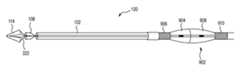
- FIG. 1is a schematic side view of an expandable tip stent-graft delivery system in accordance with one embodiment
- FIGS. 2 , 3 , 4are perspective views illustrate the expandable tip stent-graft delivery system of FIG. 1 at various stages during deployment of an expandable tip;
- FIG. 5is a partial cross-sectional view of a vascular system including the expandable tip stent-graft delivery system of FIG. 1 within a curved vessel;
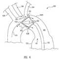
- FIG. 6is a partial cross-sectional view of the vascular system of FIG. 5 after deployment of the expandable tip of the expandable tip stent-graft delivery system;
- FIG. 7is a partial cross-sectional view of the vascular system of FIG. 6 after deployment of the expandable tip and partial deployment of a stent-graft of the expandable tip stent-graft delivery system;
- FIG. 8is a partial cross-sectional view of the vascular system of FIG. 7 after complete deployment of the stent-graft;
- FIG. 9is a schematic side view of the expandable tip stent-graft delivery system of FIG. 1 illustrating a handle of the expandable tip stent-graft delivery system
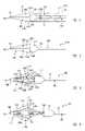
- FIGS. 10 and 11are schematic cross-sectional views of an expandable tip stent-graft delivery system at various stages during deployment of an expandable tip in accordance with another embodiment.
- a method of deploying a stent-graft 106 in a curved vessel 502 with an expandable tip stent-graft delivery system 100includes deploying an expandable tip 114 to center a distal end of the delivery catheter in curved vessel 502 as illustrating FIG. 6 .
- a sheath 102is retracted to expose stent-graft 106 as illustrated in FIG. 7 , wherein stent-graft 106 self-expands into curved vessel 502 .
- expandable tip 114is collapsed.
- the initial deployment of stent-graft 106is substantially orthogonal to the central longitudinal axis of the curved vessel 502 .
- the initial deployment of stent-graft 106is symmetric, repositioning of stent-graft 106 sometime required when using prior art systems after initial deployment is avoided. Accordingly, there is a high likelihood that the initial placement of stent-graft 106 is accurate within curved vessel 502 .
- FIG. 1is a schematic side view of an expandable tip stent-graft delivery system 100 in accordance with one embodiment.
- expandable tip stent-graft delivery system 100includes a sheath 102 , an expandable tip member 104 , a stent-graft 106 , and an inner member 108 .
- Sheath 102is a hollow tube and defines a lumen therein through which inner member 108 extends. Sheath 102 includes a distal end 102 D. Sheath 102 is illustrated as being transparent to allow visualization of features therein. However, in other examples, a sheath similar to sheath 102 is opaque.
- Inner member 108(illustrated by the dashed lines) is also a hollow tube and defines a lumen therein through which runners of expandable tip member 104 extend.
- Inner member 108includes a distal end 108 D having a cup 110 .
- Cup 110 of inner member 108has a greater diameter than the remaining proximal portion 112 of inner member 108 .
- Proximal portion 112extends proximally from cup 110 .
- cup 110is an enclosure into which runners of expandable tip member 104 are advanced and retracted to expand (deploy) and collapse an expandable tip 114 of expandable tip member 104 . Further, cup 110 has an outer diameter approximately equal to, but slightly smaller than, the inner diameter of sheath 102 facilitating a snug fit of sheath 102 around cup 110 .
- Stent-graft 106is a self-expanding stent-graft and includes a proximal end 106 P.
- Stent-graft 106includes a graft material supported by a framework.
- Stent-graft 106employs a wire or tube configured (e.g., bent or cut) to provide an outward radial force and employs a suitable elastic material such as stainless steel or Nitinol (nickel-titanium). Nitinol may additionally employ shape memory properties.
- Stent-graft 106is radially constrained by sheath 102 . More particularly, stent-graft 106 exerts an outward radial force on sheath 102 . Stent-graft 106 is radially constrained in the annular space between sheath 102 and proximal portion 112 of inner member 108 .
- FIGS. 2 , 3 , 4are perspective views illustrate expandable tip stent-graft delivery system 100 at various stages during deployment of expandable tip 114 .
- sheath 102 and stent-graft 106are not illustrated for clarity of presentation although it is to be understood that expandable tip stent-graft delivery system 100 includes sheath 102 and stent-graft 106 at the stages of deployment illustrated in FIGS. 2 , 3 , and 4 .
- expandable tip member 104includes a plurality of splines 316 A, 316 B, 316 C, 316 D, collectively splines 316 .
- expandable tip member 104includes four splines 316 although can have more or less splines in other examples.
- splines 316are long narrow strips, e.g., of nitinol, stainless steel, polymer, or other resilient material.
- splines 316are molded, e.g., from polymer.
- splines 316are connected to one another to form a distal end 114 D of expandable tip 114 .
- a guide wire opening 118is formed in distal end 114 D of expandable tip 114 .
- Each spline 316includes a tip petal 320 and a runner 322 connected to one another at an elbow 324 .
- spline 316 Aincludes a first tip petal 320 A of the plurality of tip petals 320 , a first runner 322 A of the plurality of runners 322 , and a first elbow 324 A of the plurality of elbows 324 .
- Runner 322 Ais connected to tip petal 320 A by elbow 324 A.
- the other splines 316 B, 316 C, 316 Dincludes tip petals 320 , runners 322 and elbows 324 in a similar fashion.
- Tip petals 320sometimes called wings (or fingers), extend proximally from distal end 114 D of expandable tip 114 to elbows 324 .
- Runners 322extended proximally from elbows 324 to the handle of expandable tip stent-graft delivery system 100 as discussed in greater detail below with reference to FIG. 9 .
- expandable tip 114includes a tapered outer surface that gradually increases in diameter. More particularly, the tapered outer surface has a minimum diameter at distal end 114 D of expandable tip 114 and gradually increases in diameter proximally, i.e., in the direction of the operator (or handle of expandable tip stent-graft delivery system 100 ), to have a maximum diameter at elbows 324 , which define the proximal end 114 P of expandable tip 114 .
- Other tip shapessuch as bullet-shaped tips could also be used.
- Expandable tip 114provides trackability in vessels. As set forth above, expandable tip 114 includes guide wire opening 118 therein allowing passage of a guidewire through expandable tip 114 .
- Each tip petal 320has a minimum width on the tapered outer surface of expandable tip 114 at distal end 114 D of expandable tip 114 and gradually increases in width proximally to have a maximum width at elbows 324 .
- runners 322have a substantially uniform width along the longitudinal length of runners 322 .
- runners 322have flared ends 326 at the distal end of runners 322 to match the width of tip petals 320 at elbows 324 .
- runners similar to runners 322are entirely of a uniform width, i.e., do not have flared ends 326 .
- Elbows 324are bends (or hinges) between tip petals 320 and runners 322 . Generally, outer corners of elbows 324 are smoothly rounded to prevent the corners of the elbows 324 from digging into and damaging the vessel into which elbows 324 contact as discussed further below.
- expandable tip 114is self-expanding as illustrated in FIGS. 2 , 3 and 4 .
- expandable tip 114prior to deployment of expandable tip 114 , expandable tip 114 is in its collapsed configuration. In its collapsed configuration, tip petals 320 are substantially in contact with one another along the entire length of tip petals 320 and collectively form a continuous tapered outer surface of expandable tip 114 .
- inner member 108i.e., cup 110 , radially constrains runners 322 and thus the proximal end of expandable tip 114 .
- the proximal ends of the expandable tip 114is seated on distal end 108 D of inner member 108 . More particularly, the diameter at proximal end 114 P of expandable tip 114 is greater than the diameter of cup 110 of inner member 108 .
- runners 322are advanced (moved distally (forward)) out of inner member 108 .
- Thiscauses expandable tip 114 to move distally from inner member 108 thus releasing the radial constraint of inner member 108 on runners 322 at expandable tip 114 .
- expandable tip 114begins to self-expand.
- expandable tip 114self-expands, tip petals 320 move radially outwards from one another at proximal end 114 P of expandable tip 114 .
- expandable tip 114sometimes called a flower tip, begins to open such that the outer diameter of proximal end 114 P of expandable tip 114 increases.
- runners 322are advanced out of inner member 108 to a length at which inner member 108 releases expandable tip 114 , i.e., no longer radially constrains expandable tip 114 to any significant manner. Accordingly, expandable tip 114 is in its relaxed configuration.
- tip petals 320spread outward from one another proximally from distal end 114 D of expandable tip 114 due to the self-expansion of expandable tip 114 . More particularly, tip petals 320 are separated from one another, except of course at distal end 114 D of tapered tip 114 , where tip petals 320 are connected to one another.
- expandable tip 114in its relaxed configuration as illustrated in FIG. 4 , expandable tip 114 has a greater outer diameter than in its radially contracted state as illustrated in FIG. 2 .
- This expansion of tapered tip 114is used to center stent-graft 106 (illustrated in FIG. 1 ) within a vessel prior to deployment of stent-graft 106 as discussed in greater detail below with reference to FIGS. 5 , 6 , 7 , and 8 .
- Expandable tip 114is collapsed in the opposite manner as expandable tip 114 is expanded as set forth above. More particularly, runners 322 are retracted (pulled) into inner member 108 . This causes runners 322 and thus expandable tip 114 to be radially compressed and collapsed by inner member 108 . Illustratively, expandable tip 114 goes from the stage illustrated in FIG. 4 (fully expanded), to the stage illustrated in FIG. 3 (partially expanded) to the stage illustrated in FIG. 2 (fully collapsed).
- FIG. 5is a partial cross-sectional view of a vascular system 500 including expandable tip stent-graft delivery system 100 of FIG. 1 within a curved vessel 502 .
- Curved vessel 502can be any curved vessel but is illustrated as the aortic arch in accordance with this example.
- Curved vessel 502includes an inner radius of curvature 502 I and outer radius of curvature 502 O.
- Branching from curved vessel 502are three branch vessels 504 , 506 , and 508 , e.g., the left subclavian artery (LSA), the left common carotid artery (LCC), and the brachiocephalic artery.
- LSAleft subclavian artery
- LCCleft common carotid artery
- brachiocephalic arterye.g., the brachiocephalic artery.
- three branch vessels 504 , 506 , and 508are illustrated, it is to be understood that expandable tip stent-graft delivery system 100 can be used in any vessel, i.e., with or without curves and/or with or without branch vessels.
- Expandable tip stent-graft delivery system 100is advanced over guide wire 510 , which enters expandable tip stent-graft delivery system through guide wire opening 118 in expandable tip 114 . Due to the inherent stiffness of expandable tip stent-graft delivery system 100 , expandable tip stent-graft delivery system 100 conforms to outer radius of curvature 502 O. More particularly, distal end 114 D of expandable tip 114 presses on or is located adjacent to outer radius of curvature 502 O.
- FIG. 6is a partial cross-sectional view of vascular system 500 of FIG. 5 after deployment of expandable tip 114 of expandable tip stent-graft delivery system 100 .
- expandable tip 114is deployed as discussed above in reference to FIGS. 2 , 3 , and 4 . More particularly, runners 322 are advanced out of the inner member, facilitating self expansion of expandable tip 114 .
- Self expansion of expandable tip 114causes expandable tip 114 and the distal end of the catheter attached thereto to be centered along the longitudinal axis of and within curved vessel 502 . More particularly, as tip petals 320 self-expand, one or more of tip petals 320 contact the vessel wall at or near outer radius of curvature 502 O of curved vessel 502 . This contact and expansion causes distal end 114 D of expandable tip 114 to move away from outer radius of curvature 502 O of curved vessel 502 and towards inner radius of curvature 502 I. Generally, distal end 114 D of expandable tip 114 is moved to the center of curved vessel 502 , i.e., to be located on or near a longitudinal axis L of curved vessel 502 .
- the distal end of the catheteris centered within curved vessel 502 .
- bloodi.e., fluid
- tip petals 320are separated from one another thereby forming openings for passage of blood through expandable tip 114 . Also providing a centralized alignment for the end of the catheter.
- FIG. 7is a partial cross-sectional view of vascular system 500 of FIG. 6 after deployment of expandable tip 114 and partial deployment of stent-graft 106 of expandable tip stent-graft delivery system 100 .
- proximal end 106 P of stent-graft 106is centered within curved vessel 502 by deploying expandable tip 114 as set forth above, sheath 102 is retracted to expose (deploy) stent-graft 106 .
- proximal end 106 P of stent-graft 106self expands in curved vessel 502 .
- the initial deployment of stent-graft 106is approximately (substantially) orthogonal to the longitudinal axis of curved vessel 502 , i.e., the vessel wall of curved vessel 502 .
- the initial deployment of stent-graft 106is symmetric, repositioning of stent-graft 106 as might have been done in prior art devices after initial deployment is avoided. Accordingly, stent-graft 106 is accurately placed within curved vessel 502 and deployment of additional cuff and extension stent-grafts is avoided as might have been done in prior art devices.
- FIG. 8is a partial cross-sectional view of vascular system 500 of FIG. 7 after complete deployment of stent-graft 106 (though only the proximal end of the stent graft 106 is shown).
- sheath 102is fully retracted to completely expose stent-graft 106 .
- stent graft 106is completely deployed.
- stent-graft 106acts as a conduit and seal to prevent blood flow to an aneurysm 512 in curved vessel 502 .
- expandable tip 114is collapsed as discussed above, and expandable tip stent-graft delivery system 100 is removed from the patient.
- FIG. 9is a schematic side view of expandable tip stent-graft delivery system 100 of FIG. 1 illustrating a handle 902 of expandable tip stent-graft delivery system 100 .
- Handle 902includes a forward grip 904 , forward screw threads 906 , a rear grip 908 , and rear threads 910 .
- Sheath 102is connected to rear grip 908 in a manner that allows rear grip 908 to be rotated without rotation of sheath 102 using any one of a number of techniques well known to those of skill in the art.
- Runners 322are connected to forward grip 904 in a manner that allows forward grip 904 to be rotated without rotation of runners 322 also using any one of a number of techniques well known to those of skill in the art.
- Forward grip 904is threadably engaged with forward screw threads 906 .
- Forward grip 904is rotated in a first direction on forward screw threads 906 to advance forward grip 904 and thus runners 322 to deployed expandable tip 114 as discussed above.
- forward grip 904is rotated in a second direction on forward screw threads 906 opposite the first direction to retract forward grip 904 and thus runners 322 to collapse expandable tip 114 as discussed above.
- rotation of forward grip 904causes axial translation of forward grip 904 and runners 322 .
- Rear grip 908is threadably engaged with rear screw threads 910 .
- Rear grip 908is rotated in the second direction on rear screw threads 910 to retracted rear grip 908 and thus sheath 102 to deployed stent-graft 106 (not illustrated in FIG. 9 , see FIGS. 7-8 for example) as discussed above.
- rotation of rear grip 908causes axial translation of rear grip 908 and sheath 102 .
- handle 902is set forth, an expandable tip stent-graft delivery system similar to expandable tip stent-graft delivery system 100 can be formed using any one of a number of different handles for axial translation of runners 322 and sheath 102 .
- forward grip 904 and/or rear grip 908can include buttons that allow the grips to slide and or lock in position.
- screw gearsare used to cause axial translation of runners 322 and/or sheath 102 .
- FIGS. 10 and 11are schematic cross-sectional views of an expandable tip stent-graft delivery system 100 A at various stages during deployment of an expandable tip 114 A in accordance with another embodiment.
- Expandable tip stent-graft delivery system 100 A of FIGS. 10 and 11is similar to expandable tip stent-graft delivery system 100 of FIG. 1 and includes a sheath and a stent-graft similar to sheath 102 and stent-graft 106 ( FIG. 1 ), which are not illustrated in FIGS. 10 and 11 for clarity of presentation.
- expandable tip 114 Ais mounted on a distal end 108 D of an inner member 108 A.
- Expandable tip 114 Aincludes tip petals 320 - 1 .
- Expandable tip stent-graft delivery system 100 Afurther includes a guide wire member 1030 , e.g., a tube, defining a guide wire lumen therein.
- a distal end 1030 D of guide wire member 1030is connected to distal end 114 D of expandable tip 114 A.
- proximal end 114 P of expandable tip 114 Ais mounted to inner member 108 A, proximal end 114 P is held stationery during retraction of distal end 114 D.
- expandable tip 114 Ais heat set to insure longitudinal compression of expandable tip 114 A causes tip petals 320 - 1 to bend outwards.
- expandable tip stent-graft delivery system 100 of FIG. 1includes a guide wire member similar to guide wire member 1030 of FIGS. 10 and 11 .
- This guide wire memberholds distal end 114 D of expandable tip 114 stationery during advancement and retraction of runners 322 .
Landscapes
- Health & Medical Sciences (AREA)
- Life Sciences & Earth Sciences (AREA)
- Engineering & Computer Science (AREA)
- Biomedical Technology (AREA)
- Veterinary Medicine (AREA)
- Animal Behavior & Ethology (AREA)
- Heart & Thoracic Surgery (AREA)
- Public Health (AREA)
- General Health & Medical Sciences (AREA)
- Pulmonology (AREA)
- Biophysics (AREA)
- Anesthesiology (AREA)
- Hematology (AREA)
- Oral & Maxillofacial Surgery (AREA)
- Vascular Medicine (AREA)
- Cardiology (AREA)
- Transplantation (AREA)
- Prostheses (AREA)
Abstract
Description
Claims (24)
Priority Applications (1)
| Application Number | Priority Date | Filing Date | Title |
|---|---|---|---|
| US11/734,699US8133266B2 (en) | 2007-04-12 | 2007-04-12 | Expandable tip delivery system and method |
Applications Claiming Priority (1)
| Application Number | Priority Date | Filing Date | Title |
|---|---|---|---|
| US11/734,699US8133266B2 (en) | 2007-04-12 | 2007-04-12 | Expandable tip delivery system and method |
Publications (2)
| Publication Number | Publication Date |
|---|---|
| US20080255652A1 US20080255652A1 (en) | 2008-10-16 |
| US8133266B2true US8133266B2 (en) | 2012-03-13 |
Family
ID=39854453
Family Applications (1)
| Application Number | Title | Priority Date | Filing Date |
|---|---|---|---|
| US11/734,699Expired - Fee RelatedUS8133266B2 (en) | 2007-04-12 | 2007-04-12 | Expandable tip delivery system and method |
Country Status (1)
| Country | Link |
|---|---|
| US (1) | US8133266B2 (en) |
Cited By (20)
| Publication number | Priority date | Publication date | Assignee | Title |
|---|---|---|---|---|
| US8579958B2 (en) | 2002-03-12 | 2013-11-12 | Covidien Lp | Everting stent and stent delivery system |
| US8591566B2 (en) | 2012-02-23 | 2013-11-26 | Covidien Lp | Methods and apparatus for luminal stenting |
| KR101514055B1 (en)* | 2013-12-17 | 2015-04-21 | 주식회사 스텐다드싸이텍 | Catheter for common hepatic duct |
| US9072624B2 (en) | 2012-02-23 | 2015-07-07 | Covidien Lp | Luminal stenting |
| US9078659B2 (en) | 2012-04-23 | 2015-07-14 | Covidien Lp | Delivery system with hooks for resheathability |
| US9474639B2 (en) | 2013-08-27 | 2016-10-25 | Covidien Lp | Delivery of medical devices |
| US9724222B2 (en) | 2012-07-20 | 2017-08-08 | Covidien Lp | Resheathable stent delivery system |
| US9782186B2 (en) | 2013-08-27 | 2017-10-10 | Covidien Lp | Vascular intervention system |
| US10022255B2 (en) | 2016-04-11 | 2018-07-17 | Idev Technologies, Inc. | Stent delivery system having anisotropic sheath |
| US10130500B2 (en) | 2013-07-25 | 2018-11-20 | Covidien Lp | Methods and apparatus for luminal stenting |
| US10376396B2 (en) | 2017-01-19 | 2019-08-13 | Covidien Lp | Coupling units for medical device delivery systems |
| US10786377B2 (en) | 2018-04-12 | 2020-09-29 | Covidien Lp | Medical device delivery |
| US11071637B2 (en) | 2018-04-12 | 2021-07-27 | Covidien Lp | Medical device delivery |
| US11123209B2 (en) | 2018-04-12 | 2021-09-21 | Covidien Lp | Medical device delivery |
| US11413176B2 (en) | 2018-04-12 | 2022-08-16 | Covidien Lp | Medical device delivery |
| US11413174B2 (en) | 2019-06-26 | 2022-08-16 | Covidien Lp | Core assembly for medical device delivery systems |
| US11628056B2 (en) | 2016-11-22 | 2023-04-18 | Cook Medical Technologies Llc | Graft for treating the distal aortic arch and descending aorta in type a patients |
| US11944558B2 (en) | 2021-08-05 | 2024-04-02 | Covidien Lp | Medical device delivery devices, systems, and methods |
| US12042413B2 (en) | 2021-04-07 | 2024-07-23 | Covidien Lp | Delivery of medical devices |
| US12109137B2 (en) | 2021-07-30 | 2024-10-08 | Covidien Lp | Medical device delivery |
Families Citing this family (33)
| Publication number | Priority date | Publication date | Assignee | Title |
|---|---|---|---|---|
| US8721713B2 (en) | 2002-04-23 | 2014-05-13 | Medtronic, Inc. | System for implanting a replacement valve |
| US9585743B2 (en)* | 2006-07-31 | 2017-03-07 | Edwards Lifesciences Cardiaq Llc | Surgical implant devices and methods for their manufacture and use |
| EP3360509B1 (en) | 2006-07-31 | 2022-06-22 | Syntheon TAVR, LLC | Sealable endovascular implants |
| US9408607B2 (en) | 2009-07-02 | 2016-08-09 | Edwards Lifesciences Cardiaq Llc | Surgical implant devices and methods for their manufacture and use |
| US8133266B2 (en)* | 2007-04-12 | 2012-03-13 | Medtronic Vascular, Inc. | Expandable tip delivery system and method |
| US20080255653A1 (en)* | 2007-04-13 | 2008-10-16 | Medtronic Vascular, Inc. | Multiple Stent Delivery System and Method |
| US9814611B2 (en) | 2007-07-31 | 2017-11-14 | Edwards Lifesciences Cardiaq Llc | Actively controllable stent, stent graft, heart valve and method of controlling same |
| US9566178B2 (en) | 2010-06-24 | 2017-02-14 | Edwards Lifesciences Cardiaq Llc | Actively controllable stent, stent graft, heart valve and method of controlling same |
| US10159557B2 (en) | 2007-10-04 | 2018-12-25 | Trivascular, Inc. | Modular vascular graft for low profile percutaneous delivery |
| WO2009105699A1 (en) | 2008-02-22 | 2009-08-27 | Endologix, Inc. | Design and method of placement of a graft or graft system |
| US20110054587A1 (en) | 2009-04-28 | 2011-03-03 | Endologix, Inc. | Apparatus and method of placement of a graft or graft system |
| EP2260898A1 (en)* | 2009-06-10 | 2010-12-15 | Ulrich Schäfer | Guide wire and method for its use |
| WO2011084342A1 (en)* | 2009-12-17 | 2011-07-14 | Cook Medical Technologies Llc | Delivery system with retractable proximal end |
| US20100204708A1 (en)* | 2010-02-23 | 2010-08-12 | Sanjiv Sharma | Carotid guiding catheter (sheath) for carotid percutaneous intervention/stenting with internal fixation device to prevent migration of the Carotid guiding catheter (sheath) |
| GB2485338B (en)* | 2010-11-02 | 2012-12-05 | Cook Medical Technologies Llc | Introducer assembly and dilator tip therefor |
| US20120109279A1 (en) | 2010-11-02 | 2012-05-03 | Endologix, Inc. | Apparatus and method of placement of a graft or graft system |
| EP2640319B1 (en)* | 2010-11-16 | 2016-10-19 | TriVascular, Inc. | Advanced endovascular graft and delivery system |
| US8756789B2 (en)* | 2010-11-16 | 2014-06-24 | W. L. Gore & Associates, Inc. | Method of manufacturing a catheter assembly |
| US9554904B2 (en)* | 2011-09-28 | 2017-01-31 | Medtronic CV Luxembourg S.a.r.l. | Distal tip assembly for a heart valve delivery catheter |
| US9827093B2 (en) | 2011-10-21 | 2017-11-28 | Edwards Lifesciences Cardiaq Llc | Actively controllable stent, stent graft, heart valve and method of controlling same |
| US8992595B2 (en) | 2012-04-04 | 2015-03-31 | Trivascular, Inc. | Durable stent graft with tapered struts and stable delivery methods and devices |
| US9498363B2 (en) | 2012-04-06 | 2016-11-22 | Trivascular, Inc. | Delivery catheter for endovascular device |
| WO2016022673A1 (en)* | 2014-08-05 | 2016-02-11 | Dwyer Amy C | Anti-migration stent deployment delivery systems and methods |
| US10849774B2 (en) | 2014-10-23 | 2020-12-01 | Trivascular, Inc. | Stent graft delivery system with access conduit |
| WO2017004265A1 (en) | 2015-06-30 | 2017-01-05 | Endologix, Inc. | Locking assembly for coupling guidewire to delivery system |
| US10258491B2 (en) | 2016-02-02 | 2019-04-16 | Inspiremd, Ltd. | Deformable tip for stent delivery and methods of use |
| DE102016111323A1 (en)* | 2016-06-21 | 2017-12-21 | Biotronik Ag | Insertion catheter and catheter assembly |
| GB2556116B (en)* | 2016-11-22 | 2019-12-11 | Cook Medical Technologies Llc | Graft for treating the distal aortic arch and descending aorta in type a patients |
| CN110267607B (en) | 2016-12-07 | 2023-03-21 | 波士顿科学国际有限公司 | Medical instrument |
| WO2019239409A1 (en)* | 2018-06-13 | 2019-12-19 | Endoron Medical Ltd | Graft securing system, applicator and method |
| US20230165697A1 (en)* | 2021-11-29 | 2023-06-01 | Medtronic Vascular, Inc. | Retractable, tapered tip for cardiovascular implant delivery systems |
| WO2024158626A1 (en)* | 2023-01-23 | 2024-08-02 | Edwards Lifesciences Corporation | Implant delivery and delivery system retrieval |
| CN118717356B (en)* | 2023-03-28 | 2025-09-12 | 宁波健世科技股份有限公司 | An implantable device delivery system capable of automatic centering |
Citations (8)
| Publication number | Priority date | Publication date | Assignee | Title |
|---|---|---|---|---|
| US5415664A (en)* | 1994-03-30 | 1995-05-16 | Corvita Corporation | Method and apparatus for introducing a stent or a stent-graft |
| US5685826A (en)* | 1990-11-05 | 1997-11-11 | General Surgical Innovations, Inc. | Mechanically expandable arthroscopic retractors and method of using the same |
| US20040087965A1 (en)* | 2002-11-01 | 2004-05-06 | Marc-Alan Levine | Method and apparatus for caged stent delivery |
| US20060184234A1 (en)* | 1999-09-20 | 2006-08-17 | Frazier Andrew G | Method of securing a graft |
| US20070021778A1 (en)* | 2005-06-24 | 2007-01-25 | Abbott Laboratories Abbott Vascular Devices | Apparatus and method for delivering a closure element |
| US7306617B2 (en)* | 2002-06-24 | 2007-12-11 | Cordis Corporation | Spiral centering catheter |
| US20080255652A1 (en)* | 2007-04-12 | 2008-10-16 | Medtronic Vascular, Inc. | Expandable Tip Delivery System and Method |
| US7473271B2 (en)* | 2003-04-11 | 2009-01-06 | Boston Scientific Scimed, Inc. | Stent delivery system with securement and deployment accuracy |
- 2007
- 2007-04-12USUS11/734,699patent/US8133266B2/ennot_activeExpired - Fee Related
Patent Citations (8)
| Publication number | Priority date | Publication date | Assignee | Title |
|---|---|---|---|---|
| US5685826A (en)* | 1990-11-05 | 1997-11-11 | General Surgical Innovations, Inc. | Mechanically expandable arthroscopic retractors and method of using the same |
| US5415664A (en)* | 1994-03-30 | 1995-05-16 | Corvita Corporation | Method and apparatus for introducing a stent or a stent-graft |
| US20060184234A1 (en)* | 1999-09-20 | 2006-08-17 | Frazier Andrew G | Method of securing a graft |
| US7306617B2 (en)* | 2002-06-24 | 2007-12-11 | Cordis Corporation | Spiral centering catheter |
| US20040087965A1 (en)* | 2002-11-01 | 2004-05-06 | Marc-Alan Levine | Method and apparatus for caged stent delivery |
| US7473271B2 (en)* | 2003-04-11 | 2009-01-06 | Boston Scientific Scimed, Inc. | Stent delivery system with securement and deployment accuracy |
| US20070021778A1 (en)* | 2005-06-24 | 2007-01-25 | Abbott Laboratories Abbott Vascular Devices | Apparatus and method for delivering a closure element |
| US20080255652A1 (en)* | 2007-04-12 | 2008-10-16 | Medtronic Vascular, Inc. | Expandable Tip Delivery System and Method |
Cited By (40)
| Publication number | Priority date | Publication date | Assignee | Title |
|---|---|---|---|---|
| US9849014B2 (en) | 2002-03-12 | 2017-12-26 | Covidien Lp | Medical device delivery |
| US8579958B2 (en) | 2002-03-12 | 2013-11-12 | Covidien Lp | Everting stent and stent delivery system |
| US8591566B2 (en) | 2012-02-23 | 2013-11-26 | Covidien Lp | Methods and apparatus for luminal stenting |
| US11259946B2 (en) | 2012-02-23 | 2022-03-01 | Covidien Lp | Luminal stenting |
| US9072624B2 (en) | 2012-02-23 | 2015-07-07 | Covidien Lp | Luminal stenting |
| US9192498B2 (en) | 2012-02-23 | 2015-11-24 | Covidien Lp | Luminal stenting |
| US9308110B2 (en) | 2012-02-23 | 2016-04-12 | Covidien Lp | Luminal stenting |
| US10537452B2 (en) | 2012-02-23 | 2020-01-21 | Covidien Lp | Luminal stenting |
| US9675488B2 (en) | 2012-02-23 | 2017-06-13 | Covidien Lp | Luminal stenting |
| US9724221B2 (en) | 2012-02-23 | 2017-08-08 | Covidien Lp | Luminal stenting |
| US9078659B2 (en) | 2012-04-23 | 2015-07-14 | Covidien Lp | Delivery system with hooks for resheathability |
| US9949853B2 (en) | 2012-04-23 | 2018-04-24 | Covidien Lp | Delivery system with hooks for resheathability |
| US9724222B2 (en) | 2012-07-20 | 2017-08-08 | Covidien Lp | Resheathable stent delivery system |
| US10130500B2 (en) | 2013-07-25 | 2018-11-20 | Covidien Lp | Methods and apparatus for luminal stenting |
| US9474639B2 (en) | 2013-08-27 | 2016-10-25 | Covidien Lp | Delivery of medical devices |
| US12343273B2 (en) | 2013-08-27 | 2025-07-01 | Covidien Lp | Delivery of medical devices |
| US11076972B2 (en) | 2013-08-27 | 2021-08-03 | Covidien Lp | Delivery of medical devices |
| US10045867B2 (en) | 2013-08-27 | 2018-08-14 | Covidien Lp | Delivery of medical devices |
| US10092431B2 (en) | 2013-08-27 | 2018-10-09 | Covidien Lp | Delivery of medical devices |
| US9782186B2 (en) | 2013-08-27 | 2017-10-10 | Covidien Lp | Vascular intervention system |
| US10265207B2 (en) | 2013-08-27 | 2019-04-23 | Covidien Lp | Delivery of medical devices |
| US9775733B2 (en) | 2013-08-27 | 2017-10-03 | Covidien Lp | Delivery of medical devices |
| US11103374B2 (en) | 2013-08-27 | 2021-08-31 | Covidien Lp | Delivery of medical devices |
| US10695204B2 (en) | 2013-08-27 | 2020-06-30 | Covidien Lp | Delivery of medical devices |
| US9827126B2 (en) | 2013-08-27 | 2017-11-28 | Covidien Lp | Delivery of medical devices |
| KR101514055B1 (en)* | 2013-12-17 | 2015-04-21 | 주식회사 스텐다드싸이텍 | Catheter for common hepatic duct |
| US10022255B2 (en) | 2016-04-11 | 2018-07-17 | Idev Technologies, Inc. | Stent delivery system having anisotropic sheath |
| US11628056B2 (en) | 2016-11-22 | 2023-04-18 | Cook Medical Technologies Llc | Graft for treating the distal aortic arch and descending aorta in type a patients |
| US10945867B2 (en) | 2017-01-19 | 2021-03-16 | Covidien Lp | Coupling units for medical device delivery systems |
| US11833069B2 (en) | 2017-01-19 | 2023-12-05 | Covidien Lp | Coupling units for medical device delivery systems |
| US10376396B2 (en) | 2017-01-19 | 2019-08-13 | Covidien Lp | Coupling units for medical device delivery systems |
| US11123209B2 (en) | 2018-04-12 | 2021-09-21 | Covidien Lp | Medical device delivery |
| US11071637B2 (en) | 2018-04-12 | 2021-07-27 | Covidien Lp | Medical device delivery |
| US11413176B2 (en) | 2018-04-12 | 2022-08-16 | Covidien Lp | Medical device delivery |
| US10786377B2 (en) | 2018-04-12 | 2020-09-29 | Covidien Lp | Medical device delivery |
| US11648140B2 (en) | 2018-04-12 | 2023-05-16 | Covidien Lp | Medical device delivery |
| US11413174B2 (en) | 2019-06-26 | 2022-08-16 | Covidien Lp | Core assembly for medical device delivery systems |
| US12042413B2 (en) | 2021-04-07 | 2024-07-23 | Covidien Lp | Delivery of medical devices |
| US12109137B2 (en) | 2021-07-30 | 2024-10-08 | Covidien Lp | Medical device delivery |
| US11944558B2 (en) | 2021-08-05 | 2024-04-02 | Covidien Lp | Medical device delivery devices, systems, and methods |
Also Published As
| Publication number | Publication date |
|---|---|
| US20080255652A1 (en) | 2008-10-16 |
Similar Documents
| Publication | Publication Date | Title |
|---|---|---|
| US8133266B2 (en) | Expandable tip delivery system and method | |
| US9662238B2 (en) | Attachment mechanism for stent release | |
| CN109890331B (en) | Stent-graft delivery system with a shrink sheath and method of use | |
| EP1923020B1 (en) | Stent-graft with anchoring pins | |
| US7815671B2 (en) | Controlled deployment delivery system | |
| US8876877B2 (en) | Centering for a TAA | |
| US20080228255A1 (en) | Positionable Stent-Graft Delivery System and Method | |
| JP5722764B2 (en) | Branched graft deployment system and deployment method | |
| US20080262590A1 (en) | Delivery System for Stent-Graft | |
| US20100268315A1 (en) | Castellated Sleeve Stent-Graft Delivery System and Method | |
| EP2925259A1 (en) | Prosthetic valve crimping | |
| US9763816B2 (en) | Endoluminal prosthesis delivery system and method | |
| US10610393B2 (en) | Wire retention and release mechanisms |
Legal Events
| Date | Code | Title | Description |
|---|---|---|---|
| AS | Assignment | Owner name:MEDTRONIC VASCULAR, INC., CALIFORNIA Free format text:ASSIGNMENT OF ASSIGNORS INTEREST;ASSIGNORS:THOMAS, RICHARD;CHANG, JANELLE;THOMAS, CHARLES;AND OTHERS;REEL/FRAME:019377/0036;SIGNING DATES FROM 20070517 TO 20070601 Owner name:MEDTRONIC VASCULAR, INC., CALIFORNIA Free format text:ASSIGNMENT OF ASSIGNORS INTEREST;ASSIGNORS:THOMAS, RICHARD;CHANG, JANELLE;THOMAS, CHARLES;AND OTHERS;SIGNING DATES FROM 20070517 TO 20070601;REEL/FRAME:019377/0036 | |
| ZAAA | Notice of allowance and fees due | Free format text:ORIGINAL CODE: NOA | |
| ZAAB | Notice of allowance mailed | Free format text:ORIGINAL CODE: MN/=. | |
| ZAAA | Notice of allowance and fees due | Free format text:ORIGINAL CODE: NOA | |
| STCF | Information on status: patent grant | Free format text:PATENTED CASE | |
| FPAY | Fee payment | Year of fee payment:4 | |
| MAFP | Maintenance fee payment | Free format text:PAYMENT OF MAINTENANCE FEE, 8TH YEAR, LARGE ENTITY (ORIGINAL EVENT CODE: M1552); ENTITY STATUS OF PATENT OWNER: LARGE ENTITY Year of fee payment:8 | |
| FEPP | Fee payment procedure | Free format text:MAINTENANCE FEE REMINDER MAILED (ORIGINAL EVENT CODE: REM.); ENTITY STATUS OF PATENT OWNER: LARGE ENTITY | |
| LAPS | Lapse for failure to pay maintenance fees | Free format text:PATENT EXPIRED FOR FAILURE TO PAY MAINTENANCE FEES (ORIGINAL EVENT CODE: EXP.); ENTITY STATUS OF PATENT OWNER: LARGE ENTITY | |
| STCH | Information on status: patent discontinuation | Free format text:PATENT EXPIRED DUE TO NONPAYMENT OF MAINTENANCE FEES UNDER 37 CFR 1.362 | |
| FP | Lapsed due to failure to pay maintenance fee | Effective date:20240313 |