US8133226B2 - Intramedullary fixation device for fractures - Google Patents
Intramedullary fixation device for fracturesDownload PDFInfo
- Publication number
- US8133226B2 US8133226B2US11/996,568US99656806AUS8133226B2US 8133226 B2US8133226 B2US 8133226B2US 99656806 AUS99656806 AUS 99656806AUS 8133226 B2US8133226 B2US 8133226B2
- Authority
- US
- United States
- Prior art keywords
- segment
- distal
- proximal
- guide wire
- petal
- Prior art date
- Legal status (The legal status is an assumption and is not a legal conclusion. Google has not performed a legal analysis and makes no representation as to the accuracy of the status listed.)
- Expired - Fee Related, expires
Links
Images

Classifications
- A—HUMAN NECESSITIES
- A61—MEDICAL OR VETERINARY SCIENCE; HYGIENE
- A61B—DIAGNOSIS; SURGERY; IDENTIFICATION
- A61B17/00—Surgical instruments, devices or methods
- A61B17/56—Surgical instruments or methods for treatment of bones or joints; Devices specially adapted therefor
- A61B17/58—Surgical instruments or methods for treatment of bones or joints; Devices specially adapted therefor for osteosynthesis, e.g. bone plates, screws or setting implements
- A61B17/68—Internal fixation devices, including fasteners and spinal fixators, even if a part thereof projects from the skin
- A61B17/72—Intramedullary devices, e.g. pins or nails
- A61B17/7233—Intramedullary devices, e.g. pins or nails with special means of locking the nail to the bone
- A61B17/7258—Intramedullary devices, e.g. pins or nails with special means of locking the nail to the bone with laterally expanding parts, e.g. for gripping the bone
- A61B17/7266—Intramedullary devices, e.g. pins or nails with special means of locking the nail to the bone with laterally expanding parts, e.g. for gripping the bone with fingers moving radially outwardly
- A—HUMAN NECESSITIES
- A61—MEDICAL OR VETERINARY SCIENCE; HYGIENE
- A61B—DIAGNOSIS; SURGERY; IDENTIFICATION
- A61B17/00—Surgical instruments, devices or methods
- A61B17/56—Surgical instruments or methods for treatment of bones or joints; Devices specially adapted therefor
- A61B17/58—Surgical instruments or methods for treatment of bones or joints; Devices specially adapted therefor for osteosynthesis, e.g. bone plates, screws or setting implements
- A61B17/68—Internal fixation devices, including fasteners and spinal fixators, even if a part thereof projects from the skin
- A61B17/72—Intramedullary devices, e.g. pins or nails
- A61B17/7291—Intramedullary devices, e.g. pins or nails for small bones, e.g. in the foot, ankle, hand or wrist
- A—HUMAN NECESSITIES
- A61—MEDICAL OR VETERINARY SCIENCE; HYGIENE
- A61B—DIAGNOSIS; SURGERY; IDENTIFICATION
- A61B17/00—Surgical instruments, devices or methods
- A61B17/56—Surgical instruments or methods for treatment of bones or joints; Devices specially adapted therefor
- A61B17/58—Surgical instruments or methods for treatment of bones or joints; Devices specially adapted therefor for osteosynthesis, e.g. bone plates, screws or setting implements
- A61B17/68—Internal fixation devices, including fasteners and spinal fixators, even if a part thereof projects from the skin
- A61B17/72—Intramedullary devices, e.g. pins or nails
- A61B17/7216—Intramedullary devices, e.g. pins or nails for bone lengthening or compression
- A61B17/7225—Intramedullary devices, e.g. pins or nails for bone lengthening or compression for bone compression
Definitions
- This inventionrelates to a intramedullary fixation device of the type which includes distal and proximal petals, and expansion segments, mounted on a core guide wire and relates more particularly, though not exclusively, to such a device that is adjustable in length. More preferably, though not exclusively, the device can provide both torsional and longitudinal stability for fixing the fractured metacarpal bones, metatarsal bones in the foot and the phalanges of the fingers and toes, or bones of similar structure.
- Metacarpal and proximal phalangeal fracturesare commonly encountered in hand fractures. The majority of these fractures can be treated non-operatively with good functional outcome. However, some unstable fractures with shortening or rotational deformities will require surgical intervention.
- fixationFor all metacarpal fractures, proper fixation has always been the most important means for proper healing.
- fixation methodswhich are mainly in two categories—external and internal fixations.
- External fixationusually by means of splints or casts, is used in cases in which the bone pieces are lined up well and surgery may not be necessary.
- some more complicated casesrequire operative treatment with insertion of an implant to fix the fracture.
- a good internal fixationshould have the merits of least exposure, least damage to soft tissue, and ease of manipulation.
- K wire fixationThere are generally four internal fixation methods currently used by clinicians for metacarpal fractures. They are Kirsches-wire (K wire) fixation, screw fixation, plate fixation, and pin fixation. Though these fixation methods have their own merits in dealing with different type of fractures, they have various shortcomings when applied to hand metacarpal fractures. Advantages of using K wires include minimal exposure and penetration of bone, short hospital stay, early mobilization, and few complications. However, it has the disadvantage of relatively weak fixation. Screw fixation can provide rigid compression loading of fracture site, but greater exposure is required for drilling. Plate fixation is designed to provide rigid internal fixation in order to facilitate early motion and thereby minimise joint and tendon complications. However the technique is demanding and secondary procedures are frequently required. A pin fixation is the insertion of a fixation pin into the medullary canal of a fractured metacarpal for stable bone fixation. The frequent complication rates emphasize the need for meticulous pin placement, adequate intraoperative evaluation of pin position, and satisfactory patient compliance.
- U.S. Pat. No. 6,533,788 B1(Orbay) relates to a locking device and method for fixation pin stabilization within a fractured bone.
- This locking deviceincludes a locking sleeve and a handle.
- This inventionproduces a device that provides torsional and longitudinal stability to the fixation pin and thereby to the bone through which the fixation pin extends.
- this inventionstill adopts the idea of using a fixation pin for the intramedullary stabilization, it has relatively weak fixation, especially in the distal end of the pin where there is no locking device.
- other disadvantagessuch as, for example, frequent complication rates, the need for meticulous pin placement, adequate intraoperative evaluation of pin position, and patient compliance still remain.
- an intramedullary fixation devicefor fractures.
- the intramedullary fixation devicecompromises a core guide wire, and distal and proximal petal segments mountable on the core guide wire and being able to be moved towards each other.
- Each petal segmenthas multiple petals able to be expanded for gripping an internal wall of a medullary canal.
- the devicealso has expansion segments mountable on the core guide wire.
- Each expansion segmenthas a tapered engagement surface for engaging with and expanding the petals of the distal and proximal petal segments.
- the core guide wiremay have a leading end portion, a middle portion and a trailing end portion.
- the leading end portionmay serve as a stopper for the distal petal segment.
- the middle portionmay have external screw threading for engaging a threaded bore of the distal and proximal petals for threadingly mounting the distal and proximal petals on the middle portion.
- the trailing end portionmay be for convenience of holding.
- the intramedullary fixation devicemay further comprise a distal connecting segment with a counter-sink at one end to match the expansion segment, the other end being counter-bored.
- the intramedullary fixation devicemay further comprise a proximal connecting segment having a counter-sink at one end to match the expansion segment, the other end having a protrusion.
- the intramedullary fixation devicemay further comprise at least one optional segment with a protrusion at one end and a counter-bore at the other end.
- the distal and proximal petal segmentsmay be mounted on the core guide wire in an opposed relationship.
- the expansion segmentsmay each have a chamfer to match a connecting segment.
- Each petal segmentmay comprise a tapered internal surface for accommodating the expansion segment.
- a multipiece assembly for intramedullary fixationcomprising distal and proximal petal segments able to be expanded to grip an internal medullary canal wall so as to provide a stable fixation, an expansion segment for each of the distal and proximal petal segments for forcing the distal and proximal petal segments to be expanded upon tightening, and a core wire upon which the distal and proximal petal segments, and the expansion segments, are mounted, the core wire also being for effecting the tightening so as to form a rigid structure.
- the core wiremay have external screw threading, and there may be connecting segments and optional segments for enabling the multipiece assembly to be adjustable in length.
- the distal and proximal petal segmentsmay each have an internal screw thread for mounting on the core guide wire and for controlling the axial position of the petal segment.
- Each petal segmentmay comprise a plurality of evenly distributed petals, and a tapered internal surface for accommodating the expansion segment.
- a method for intramedullary fixation of a fracturecomprising:
- Rotation of the core guide wiremay cause the distal and proximal petal segments to move towards each other.
- step (f)Alternatively after step (f) and before step (c):
- the advantage of this devicelies in that it is able to provide reliable torsional and longitudinal stability by means of the grip of the expanded petals onto the internal medullary wall.
- Another advantage of the devicelies in that it is adjustable in length, which can accommodate the variation in metacarpal lengths of different patients or the variation in bone lengths when the device is extended to be applied in other similar bones.
- the devicemay be used for any other fractures and for any long bone so long as the device is proportionally sized, i.e. adjustable to the appropriate length.
- the implantis designed to provide sufficient stability to the fracture fixation so the doctor may be able to order immediate appropriate rehabilitation care for the patient.
- the inwards compressive force of the fixationmay aid fracture healing.
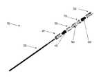
- FIG. 1is a perspective view of components of the fixation assembly illustrated in longitudinally spaced relation relative to each other;
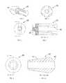
- FIG. 2is an elevational view of the core guide wire
- FIG. 3is an enlarged elevational view of the head of core guide wire in FIG. 2 ;
- FIG. 4is a perspective view of the distal/proximal petal
- FIG. 5is a left end view of the petal illustrated in FIG. 4 ;
- FIG. 6is a right end view of the petal illustrated in FIG. 4 ;
- FIG. 7is a sectional view taken along line C-C of FIG. 6 ;
- FIG. 8is a small-size end view of the expansion segment illustrated in FIG. 1 ;
- FIG. 9is a sectional view taken along line D-D of FIG. 8 ;
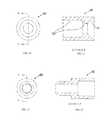
- FIG. 10is the right end view of the distal connecting segment illustrated in FIG. 1 ;
- FIG. 11is the sectional view taken along line E-E of FIG. 10 ;
- FIG. 12is the left (small-size) end view of the optional segment illustrated in FIG. 1 ;
- FIG. 13is the sectional view taken along line F-F of FIG. 12 ;
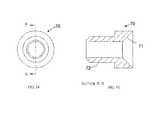
- FIG. 14is the left (small-size) end view of the proximal connecting segment illustrated ion FIG. 1 ;
- FIG. 15is the sectional view taken along line G-G of FIG. 14 ;
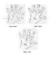
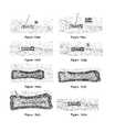
- FIG. 16 ( a )-( l )shows the surgical insertion of the implant according to an embodiment of the invention.
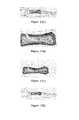
- FIG. 17 ( a )-( f )shows the surgical removal of the implant according to an embodiment of the invention.
- any implantmust be able to accommodate changes in bone length. It is estimated that the medullary canal of the metacarpal bone is about half the diameter of the outer bone shell. The smallest diameter of the metacarpal bones has been found to be about 6.19 mm. Therefore, the maximum external diameter of any implant should be about 3.0 mm.
- the implantmay withstand a load of 2 Kg applied to the tip of the finger. However, the dimensions and load will vary from patient-to-patient, and according to the bones concerned.
- FIG. 1schematically illustrates a perspective view of components of the fixation assembly in longitudinally spaced relation relative to each other, in its entirety by reference numeral 10 .
- distal petal segment 30 , distal expansion segment 40 , distal connecting segment 50 , optional segment 60 , proximal connecting segment 70 , proximal expansion segment 40 ′, and proximal petal segment 30 ′are able to be mounted upon the core guide wire 20 in sequence and tightened to form a rigid rod fixation assembly 10 .
- distal/proximal petal segments 30 / 30 ′When tightened, the distal/proximal petal segments 30 / 30 ′ will be expanded by the distal/proximal expansion segments 40 / 40 ′ and will therefore grip onto the internal medullary wall of the bone, such as, for example, a metacarpal bone.
- FIG. 2 and FIG. 3show the core guide wire 20 .
- Core guide wire 20may be fabricated from K-Wire that is commonly used in surgical procedures.
- the core guide wire 20has a leading end portion 21 , a middle portion with external screw threading 22 , and a trailing end portion 23 .
- the leading end portion 21serves as a stopper for subsequent segments 30 , 40 , 50 , 60 , 70 , 40 ′, and 30 ′, particularly the distal petal segment 30 .
- the trailing end portionis for the convenience of holding.
- the core guide wire 20will be introduced into the medullary canal to guide a reaming tool for enlarging the medullary canal, as well as for assembling and holding of the various segments.
- FIGS. 4 , 5 , 6 and 7illustrate the distal and proximal petal segments 30 and 30 ′. They are mounted on the core guide wire 20 in an opposed orientation. They are identical so that they can be used interchangeably to minimise any potential error due to wrong assembly. Screw threads 33 are formed in the bore of the petal segments 30 , 30 ′ for engaging the threaded portion 22 on the core guide wire 20 and to control the axial position of the petal 30 . Therefore, as the core guide wire 20 is rotated, and as the distal 30 and proximal petal segments 30 face in opposite directions, they will be drawn towards each other by the interaction of the screw threads 22 , 33 .
- the four petals 31 of each of the petal segments 30 , 30 ′will expand when the expansion segment 40 is pressed into the tapered portion 32 , and thus will grip onto the internal wall of the medullary canal. This provides a stable fixation and prevents relative movement.
- the petals 31 of both distal 30 and proximal 30 ′ petalswill be forced against the internal wall and thus provide a compressive force on the medullary canal wall. This force also produces a force by the distal 30 and proximal petal 30 ′ towards each other by virtue of the interaction of the screw threads 22 , 33 .
- the external surface of the petals 31may be coated or textured to provide better grip.
- a proposed material for this componentis stainless steel or titanium.
- the petals 31are preferably evenly distributed around the petal segments 30 , 30 ′.
- FIGS. 8 and 9illustrate the distal and proximal expansion segments 40 and 40 ′, designed to be identical for use interchangeably and to minimise any potential error due to wrong assembly.
- the tapered surface 41 of the expansion segmentis used to force open the petals 31 when all components are tightened together.
- the tapered surface 41 of the expansion segments 40 , 40 ′is preferably polished to a fine finish for easy sliding into the petals 31 .
- the other end of the expansion segments 40 , 40 ′is a chamfer 42 to match the connecting segment 50 or 70 .
- the chamfer 42is to provide self-compliance when assembled and is preferably polished.
- a proposed material for this componentis stainless steel or titanium.
- FIGS. 10 and 11illustrate the distal connecting segment 50 , designed with a counter-sink 51 on one end that matches the chamfer 42 of the expansion segments 40 , 40 ′ so as to receive therein the chamfer 42 with self-compliance. Its opposite end is counter bored 52 to mate with the protrusion 61 of the optional segment 60 or the protrusion 72 of the proximal connecting segment 70 such that, when the assembly is tightened, a rigid structure results.
- the tolerances of the mating surfacesare preferably well controlled to assure proper functioning of the implant.
- a proposed material for this componentis stainless steel or titanium.
- FIGS. 12 and 13illustrate the optional segment 60 , designed with a protrusion 61 and a counter-bore 62 on each end.
- the counter-bore 62is adapted to receive therein the protrusion 61 of an adjacent optional segment 60 , or the protrusion 72 of the proximal connecting segment 70 .
- Multiple pieces of the optional segmentscan be assembled to vary the length of the implant for catering to varying lengths of the relevant bones. While providing flexibility to vary the implant length, the optional segment is also flexible when loose, but becomes a rigid structure when tightened as the segments interlock with each other.
- the tolerance of the mating surfaces 61 and 62are preferably well controlled to assure proper functioning of the implant.
- a proposed material for this componentis stainless steel or titanium.
- FIGS. 14 and 15illustrate the proximal connecting segment 70 , designed with a countersink 71 on one end to match the expansion segment 40 ′ with self-compliance; while its opposite end has a protrusion 72 that matches with the counterbore 62 of the optional segment 60 and the counterbore 52 of the distal connection segment such that when the assembly is tightened, a rigid structure results.
- the protrusions 72 and 61are preferably of the same external diameter, and the same axial length.
- the length of protrusions 72 and 61should match the length of counterbores 62 and 52 .
- the tolerance of the mating surfaces 71 and 72should be well controlled to assure proper functioning of the implant. Examples of materials that can be used for this component are stainless steel and titanium.
- All the components 40 , 50 , 60 70 and 40 ′have a central bore 43 , 53 , 63 and 73 respectively that is not threaded and is relatively smooth to enable them to be an easy, sliding fit on core guide wire 20 .
- the core guide wire 20 with its leading end portion and screw-threaded middle portion 22is required, as are the distal 30 and proximal petal segments 30 ′, and the distal and proximal expansion segments 40 , 40 ′.
- the connecting segments 50 , 70 , and the optional segment(s) 60may be used to adjust the axial length of the assembly.
- the present inventionalso provides a method of intramedullary fixation of a fracture.
- the core guide wire 20with the distal petal segment 30 mounted thereon adjacent the leading end portion 21 , is inserted into the medullary cavity and engage its wall on the far side of the fracture.
- Distal expansion segment 40is then passed over the core guide wire 20 until it engages the distal petal segment 30 .
- the distal connecting portion 50is then passed along the core guide 20 until it engages the distal expansion segment 40 . If required, one or more optional segments 60 are then passed along core guide wire 20 until it or they engage the distal connecting segment 50 .
- proximal connecting segment 70proximal expansion segment 40 ′ and, finally, the proximal petal segment 30 ′.
- the proximal petal segment 30 ′will engage the medullary cavity wall on the near side of the fracture.
- the core guide wire 20is rotated to cause the two petal segments 30 , 30 ′ to expand under the influence of the expansion segments 40 , 40 ′ respectively; and to move towards each other. This caused the petals 31 to expand to engage the medullary canal wall, and to force the fracture closed. When sufficiently tight, rotation of the core guide wire 20 can stop.
- engaging projections and counterbores, and chamfers and countersinksare described, other mating structures for enabling one segment to cause the rotation of an adjacent segment may be used.
- FIG. 16The surgical procedure for the insertion of the intra-medullary metacarpal implant into the medullary canal of a fractured metacarpal bone for stable bone fixation is illustrated in FIG. 16 and described as follows:
- FIG. 17The surgical procedure for the removal of the intra-medullary metacarpal implant is illustrated in FIG. 17 and described as follows:
- the implantbeing adjustable in length
- the implantmay be used for any other fractures and for any long bone so long as the implant is proportionally sized, i.e. adjustable to the appropriate length.
Landscapes
- Health & Medical Sciences (AREA)
- Orthopedic Medicine & Surgery (AREA)
- Surgery (AREA)
- Life Sciences & Earth Sciences (AREA)
- Heart & Thoracic Surgery (AREA)
- Nuclear Medicine, Radiotherapy & Molecular Imaging (AREA)
- Engineering & Computer Science (AREA)
- Biomedical Technology (AREA)
- Neurology (AREA)
- Medical Informatics (AREA)
- Molecular Biology (AREA)
- Animal Behavior & Ethology (AREA)
- General Health & Medical Sciences (AREA)
- Public Health (AREA)
- Veterinary Medicine (AREA)
- Surgical Instruments (AREA)
Abstract
Description
- (a) passing a core guide wire with a distal petal segment mounted thereon into the medullary cavity such that the distal petal segment is in the medullary canal on a far side of the fracture;
- (b) passing a distal expansion segment along the core guide wire until it engages the distal petal segment;
- (c) passing a proximal expansion segment along the core guide wire;
- (d) passing a proximal petal segment along the core guide wire until it engages the proximal expansion segment on a near side of the fracture;
- (e) rotating the core guide wire to cause the distal and proximal petal segments to expand under the influence of the distal and proximal expansion segments such that the proximal and distal petal segment will securely engage the medullary cavity wall.
- (f) a distal connecting segment may be passed along the core guide wire until it engages the distal expansion segment.
- (g) at least one optional segment may be passed along the core guide wire until it engages the distal connecting segment.
- (g) a proximal connecting segment may be passed along the core guide wire until it engages the distal connecting segment. A proximal connecting segment may then be passed along the core guide wire until it engages the at least one optional portion.
- (a) A
small incision 75 is made in the skin proximal to the metacarpal bone on the dorsal side of the palm, at the base of the fractured metacarpal bone. The example inFIG. 16( a) shows the 3rdmetacarpal bone. - (b) The
incision 75 is then stretched sufficiently to expose the base of the bone. - (c) An aur is inserted through the incision and is used to drill a small hole into the base of the metacarpal bone.
- (d) The core guide wire (treaded K wire)20 is inserted through the drilled hole into the intra-medullary canal. Insertion is guided by radiological assistance. The
core guide wire 20 is passed through the fracture site up to the neck of the metacarpal bone. - (e) A
reamer 80 is introduced through thecore guide wire 20 to bore a hole in the intra-medullary canal to the required diameter. - (f) The
reamer 80 is then removed from the medullary canal making sure that thecore guide wire 20 is still in its original position. The components of the intra-medullary implant are inserted into the bored hole in the following sequence (as shown inFIG. 1 and described above):- (i)
Distal Petal 30 - (ii)
Distal Expansion Segment 40 - (iii)
Distal Connecting Segment 50 - (iv)
Optional Segment 60 - (v)
Proximal Connecting Segment 70 - (vi)
Proximal Expansion Segment 40′ - (vii)
Proximal Petal 30′
- (i)
- (g) The
distal petal 30 is threaded along thecore guide wire 20 until it reaches the end of thecore guide wire 20. - (h) The other components of the implant are inserted into the bored hole in the medullary canal of the metacarpal bone, along the
core guide wire 20 in the sequence shown in step (g) and ending with theproximal petal 30′. - (i) The
proximal petal 30′ is then tightened with a petal screwdriver. - (j) Further tightening of the
proximal petal 30′ forces the four ‘fingers’ of the distal andproximal petals proximal petals - (k) The excess
core guide wire 20 that is extending through theincision 75 is then cut off. - (l) The
incision 75 is stitched up.
- (a) The stitches are removed from the
incision 75 to re-expose the bone. - (b) The
incision 75 is stretched sufficiently to expose the base of the bone - (c) The cut end of the
core guide wire 20 is located. - (d) The
proximal petal 30′ is loosened and removed with a petal screwdriver. - (e) The
core guide wire 20 is pulled and pushed with a pair of pliers; at the same time, a clockwise and counter-clockwise twist is applied on thecore guide wire 20. The motion is repeated where necessary. These series of motion will loosen the components and allows the fingers on thedistal petal 30 to contract, releasing its grip on the medullary canal wall. - (f) The implant is gently pulled out when the components have sufficiently loosen in the medullary canal.
Claims (12)
Priority Applications (1)
| Application Number | Priority Date | Filing Date | Title |
|---|---|---|---|
| US11/996,568US8133226B2 (en) | 2005-07-12 | 2006-07-11 | Intramedullary fixation device for fractures |
Applications Claiming Priority (3)
| Application Number | Priority Date | Filing Date | Title |
|---|---|---|---|
| US69866705P | 2005-07-12 | 2005-07-12 | |
| US11/996,568US8133226B2 (en) | 2005-07-12 | 2006-07-11 | Intramedullary fixation device for fractures |
| PCT/SG2006/000192WO2007008177A1 (en) | 2005-07-12 | 2006-07-11 | Intramedullary fixation device for fractures |
Publications (2)
| Publication Number | Publication Date |
|---|---|
| US20080294163A1 US20080294163A1 (en) | 2008-11-27 |
| US8133226B2true US8133226B2 (en) | 2012-03-13 |
Family
ID=37637431
Family Applications (1)
| Application Number | Title | Priority Date | Filing Date |
|---|---|---|---|
| US11/996,568Expired - Fee RelatedUS8133226B2 (en) | 2005-07-12 | 2006-07-11 | Intramedullary fixation device for fractures |
Country Status (2)
| Country | Link |
|---|---|
| US (1) | US8133226B2 (en) |
| WO (1) | WO2007008177A1 (en) |
Cited By (16)
| Publication number | Priority date | Publication date | Assignee | Title |
|---|---|---|---|---|
| US20100331842A1 (en)* | 2006-02-03 | 2010-12-30 | Milbank Miles C | Multi-articulated fracture fixation device with adjustable modulus of rigidity |
| US20110125272A1 (en)* | 2009-11-20 | 2011-05-26 | Knee Creations, Llc | Bone-derived implantable devices for subchondral treatment of joint pain |
| US8821504B2 (en) | 2009-11-20 | 2014-09-02 | Zimmer Knee Creations, Inc. | Method for treating joint pain and associated instruments |
| US8864768B2 (en) | 2009-11-20 | 2014-10-21 | Zimmer Knee Creations, Inc. | Coordinate mapping system for joint treatment |
| US8906032B2 (en) | 2009-11-20 | 2014-12-09 | Zimmer Knee Creations, Inc. | Instruments for a variable angle approach to a joint |
| US9033987B2 (en) | 2009-11-20 | 2015-05-19 | Zimmer Knee Creations, Inc. | Navigation and positioning instruments for joint repair |
| US9259257B2 (en) | 2009-11-20 | 2016-02-16 | Zimmer Knee Creations, Inc. | Instruments for targeting a joint defect |
| US9271835B2 (en) | 2009-11-20 | 2016-03-01 | Zimmer Knee Creations, Inc. | Implantable devices for subchondral treatment of joint pain |
| US9717544B2 (en) | 2009-11-20 | 2017-08-01 | Zimmer Knee Creations, Inc. | Subchondral treatment of joint pain |
| US9827025B2 (en) | 2015-11-20 | 2017-11-28 | Globus Medical, Inc. | Expandable intramedullary systems and methods of using the same |
| US9974581B2 (en) | 2015-11-20 | 2018-05-22 | Globus Medical, Inc. | Expandable intramedullary systems and methods of using the same |
| US10092333B2 (en) | 2015-11-20 | 2018-10-09 | Globus Medical, Inc. | Expandable intramedullary systems and methods of using the same |
| US20190029738A1 (en)* | 2014-01-22 | 2019-01-31 | Globus Medical, Inc. | Intramedullary nails |
| US10568670B2 (en)* | 2016-09-19 | 2020-02-25 | Universitat Politecnica De Valencia | Intramedullary fixation device |
| US10953204B2 (en) | 2017-01-09 | 2021-03-23 | Boston Scientific Scimed, Inc. | Guidewire with tactile feel |
| US11369422B1 (en)* | 2020-12-15 | 2022-06-28 | Orthopedic Designs North America, Inc. | Bone fixation tangs with self-balancing extension |
Families Citing this family (22)
| Publication number | Priority date | Publication date | Assignee | Title |
|---|---|---|---|---|
| US7785325B1 (en)* | 2006-02-03 | 2010-08-31 | Milbank Miles C | Multi-articulated fracture fixation device with adjustable modulus of rigidity |
| CA2682298C (en)* | 2007-02-23 | 2015-04-28 | Zimmer Gmbh | Implant for fracture treatment |
| AU2008228710A1 (en) | 2007-03-22 | 2008-09-25 | Novalign Orthopaedics, Inc. | Segmented intramedullary structure |
| CA2781407A1 (en) | 2008-01-14 | 2009-07-23 | Michael P. Brenzel | Apparatus and methods for fracture repair |
| US20120065638A1 (en)* | 2009-05-21 | 2012-03-15 | Sonoma Orthopedic Products, Inc. | Snap and twist segmented intramedullary system, apparatus and associated methods |
| US20110178520A1 (en) | 2010-01-15 | 2011-07-21 | Kyle Taylor | Rotary-rigid orthopaedic rod |
| WO2011091052A1 (en) | 2010-01-20 | 2011-07-28 | Kyle Taylor | Apparatus and methods for bone access and cavity preparation |
| WO2011112615A1 (en) | 2010-03-08 | 2011-09-15 | Krinke Todd A | Apparatus and methods for securing a bone implant |
| EP3326558B1 (en) | 2011-11-14 | 2025-04-30 | The University of British Columbia | Intramedullary fixation system for management of pelvic and acetabular fractures |
| US9351771B2 (en) | 2013-02-08 | 2016-05-31 | Robert Gorsline | Systems, methods, and apparatuses for fusion, stabilization, or fixation of bones |
| EP2961337B1 (en) | 2013-02-28 | 2021-04-28 | Feibel, Jonathan | Systems and apparatuses for reaming bone elements |
| US9421049B2 (en) | 2013-09-06 | 2016-08-23 | Richard A. Rogachefsky | Intramedullary rod fixation system |
| CN105939677A (en) | 2013-12-12 | 2016-09-14 | 康文图斯整形外科公司 | Tissue displacement tools and methods |
| WO2015134750A1 (en) | 2014-03-06 | 2015-09-11 | University Of British Columbia | Shape adaptable intramedullary fixation device |
| JP6389002B2 (en)* | 2014-10-14 | 2018-09-12 | ザ ユニヴァーシティ オブ ブリティッシュ コロンビア | System and method for intramedullary bone fixation |
| US10335282B2 (en) | 2016-02-09 | 2019-07-02 | Richard A. Rogachefsky | Magnetic joint replacement |
| EP3522803A4 (en) | 2016-10-05 | 2020-05-27 | The University of British Columbia | Intramedullary fixation device with shape locking interface |
| WO2019010252A2 (en) | 2017-07-04 | 2019-01-10 | Conventus Orthopaedics, Inc. | APPARATUS AND METHODS FOR TREATING BONES |
| US11580268B2 (en) | 2018-04-25 | 2023-02-14 | Loubert S. Suddaby | Method of creating a customized segmented alignment rod for alignment of a spine |
| US11317949B2 (en) | 2018-04-25 | 2022-05-03 | Loubert S. Suddaby | Segmented alignment rod assembly |
| US10624683B2 (en) | 2018-04-25 | 2020-04-21 | Loubert S. Suddaby | Segmented alignment rod assembly |
| CN112912022A (en) | 2018-10-17 | 2021-06-04 | 不列颠哥伦比亚大学 | Bone fixation device and system |
Citations (15)
| Publication number | Priority date | Publication date | Assignee | Title |
|---|---|---|---|---|
| US3986504A (en)* | 1974-10-25 | 1976-10-19 | Rafael Pares Avila | Internal fixation device for securing two fractured bone joints together |
| US4364382A (en) | 1979-08-23 | 1982-12-21 | Ulrich Mennen | Internal fixation device for bone fractures |
| GB2269108A (en) | 1992-06-30 | 1994-02-02 | Lev Bimman | Apparatus for intramedullary fixation of broken elongate bones |
| WO1996002201A1 (en) | 1994-07-15 | 1996-02-01 | Smith & Nephew Richards Inc. | Cannulated modular intramedullary nail |
| US5531792A (en) | 1994-06-14 | 1996-07-02 | Huene; Donald R. | Bone plug fixation assembly, expansible plug assembly therefor, and method of fixation |
| US5534004A (en)* | 1993-07-23 | 1996-07-09 | Santangelo; Massimo | Device for preventive support of the femur |
| US5667510A (en) | 1995-08-03 | 1997-09-16 | Combs; C. Robert | Joint fixation system and method |
| US5702215A (en) | 1995-06-05 | 1997-12-30 | Li Medical Technologies, Inc. | Retractable fixation device |
| US5814071A (en)* | 1994-11-10 | 1998-09-29 | Innovasive Devices, Inc. | Suture anchor assembly and methods |
| US20030039453A1 (en)* | 2001-08-24 | 2003-02-27 | Holmquist Marlon E. | Strain relief boot; optical connector and boot assembly; and methods |
| US6575973B1 (en)* | 2000-10-26 | 2003-06-10 | Safedrip Ltd. | Self locking intramedullary nail |
| US20060229617A1 (en)* | 2005-02-25 | 2006-10-12 | Orthomechanics Ltd. | Intramedullary devices and methods of deploying the same |
| US20060241576A1 (en)* | 2002-01-15 | 2006-10-26 | Diederich Chris J | System and method providing directional ultrasound therapy to skeletal joints |
| US20060264951A1 (en)* | 2005-05-18 | 2006-11-23 | Nelson Charles L | Minimally Invasive Actuable Bone Fixation Devices Having a Retractable Interdigitation Process |
| US20080262495A1 (en)* | 2004-03-31 | 2008-10-23 | Orthofix S.R.L | Intramedullary Nail Comprising Elements of Shape-Memory Material |
- 2006
- 2006-07-11WOPCT/SG2006/000192patent/WO2007008177A1/enactiveApplication Filing
- 2006-07-11USUS11/996,568patent/US8133226B2/ennot_activeExpired - Fee Related
Patent Citations (16)
| Publication number | Priority date | Publication date | Assignee | Title |
|---|---|---|---|---|
| US3986504A (en)* | 1974-10-25 | 1976-10-19 | Rafael Pares Avila | Internal fixation device for securing two fractured bone joints together |
| US4364382A (en) | 1979-08-23 | 1982-12-21 | Ulrich Mennen | Internal fixation device for bone fractures |
| GB2269108A (en) | 1992-06-30 | 1994-02-02 | Lev Bimman | Apparatus for intramedullary fixation of broken elongate bones |
| US5534004A (en)* | 1993-07-23 | 1996-07-09 | Santangelo; Massimo | Device for preventive support of the femur |
| US5531792A (en) | 1994-06-14 | 1996-07-02 | Huene; Donald R. | Bone plug fixation assembly, expansible plug assembly therefor, and method of fixation |
| WO1996002201A1 (en) | 1994-07-15 | 1996-02-01 | Smith & Nephew Richards Inc. | Cannulated modular intramedullary nail |
| US5489284A (en) | 1994-07-15 | 1996-02-06 | Smith & Nephew Richards Inc. | Cannulated modular intramedullary nail |
| US5814071A (en)* | 1994-11-10 | 1998-09-29 | Innovasive Devices, Inc. | Suture anchor assembly and methods |
| US5702215A (en) | 1995-06-05 | 1997-12-30 | Li Medical Technologies, Inc. | Retractable fixation device |
| US5667510A (en) | 1995-08-03 | 1997-09-16 | Combs; C. Robert | Joint fixation system and method |
| US6575973B1 (en)* | 2000-10-26 | 2003-06-10 | Safedrip Ltd. | Self locking intramedullary nail |
| US20030039453A1 (en)* | 2001-08-24 | 2003-02-27 | Holmquist Marlon E. | Strain relief boot; optical connector and boot assembly; and methods |
| US20060241576A1 (en)* | 2002-01-15 | 2006-10-26 | Diederich Chris J | System and method providing directional ultrasound therapy to skeletal joints |
| US20080262495A1 (en)* | 2004-03-31 | 2008-10-23 | Orthofix S.R.L | Intramedullary Nail Comprising Elements of Shape-Memory Material |
| US20060229617A1 (en)* | 2005-02-25 | 2006-10-12 | Orthomechanics Ltd. | Intramedullary devices and methods of deploying the same |
| US20060264951A1 (en)* | 2005-05-18 | 2006-11-23 | Nelson Charles L | Minimally Invasive Actuable Bone Fixation Devices Having a Retractable Interdigitation Process |
Non-Patent Citations (1)
| Title |
|---|
| International Search Report and Written Opinion for PCT/SG2006/000192. |
Cited By (30)
| Publication number | Priority date | Publication date | Assignee | Title |
|---|---|---|---|---|
| US8372074B2 (en)* | 2006-02-03 | 2013-02-12 | Miles C. Milbank | Multi-articulated fracture fixation device with adjustable modulus of rigidity |
| US20100331842A1 (en)* | 2006-02-03 | 2010-12-30 | Milbank Miles C | Multi-articulated fracture fixation device with adjustable modulus of rigidity |
| US9439765B2 (en) | 2009-11-20 | 2016-09-13 | Zimmer Knee Creations, Inc. | Method for subchondral treatment of joint pain using implantable devices |
| US9351746B2 (en) | 2009-11-20 | 2016-05-31 | Zimmer Knee Creations, Inc. | Coordinate mapping system for joint treatment |
| US8821504B2 (en) | 2009-11-20 | 2014-09-02 | Zimmer Knee Creations, Inc. | Method for treating joint pain and associated instruments |
| US8864768B2 (en) | 2009-11-20 | 2014-10-21 | Zimmer Knee Creations, Inc. | Coordinate mapping system for joint treatment |
| US9730744B2 (en) | 2009-11-20 | 2017-08-15 | Zimmer Knee Creations, Inc. | Method for treating joint pain and associated instruments |
| US9033987B2 (en) | 2009-11-20 | 2015-05-19 | Zimmer Knee Creations, Inc. | Navigation and positioning instruments for joint repair |
| US9119721B2 (en) | 2009-11-20 | 2015-09-01 | Zimmer Knee Creations, Inc. | Method for treating joint pain and associated instruments |
| US9259257B2 (en) | 2009-11-20 | 2016-02-16 | Zimmer Knee Creations, Inc. | Instruments for targeting a joint defect |
| US9271835B2 (en) | 2009-11-20 | 2016-03-01 | Zimmer Knee Creations, Inc. | Implantable devices for subchondral treatment of joint pain |
| US20110125272A1 (en)* | 2009-11-20 | 2011-05-26 | Knee Creations, Llc | Bone-derived implantable devices for subchondral treatment of joint pain |
| US9351835B2 (en) | 2009-11-20 | 2016-05-31 | Zimmer Knee Creations, Inc. | Method for treating joint pain and associated instruments |
| US9386996B2 (en) | 2009-11-20 | 2016-07-12 | Zimmer Knee Creations, Inc. | Navigation and positioning instruments for joint repair |
| US8801800B2 (en) | 2009-11-20 | 2014-08-12 | Zimmer Knee Creations, Inc. | Bone-derived implantable devices and tool for subchondral treatment of joint pain |
| US11006992B2 (en) | 2009-11-20 | 2021-05-18 | Zimmer Knee Creations, Inc. | Method for treating joint pain and associated instruments |
| US8906032B2 (en) | 2009-11-20 | 2014-12-09 | Zimmer Knee Creations, Inc. | Instruments for a variable angle approach to a joint |
| US9717544B2 (en) | 2009-11-20 | 2017-08-01 | Zimmer Knee Creations, Inc. | Subchondral treatment of joint pain |
| US10271883B2 (en) | 2009-11-20 | 2019-04-30 | Zimmer Knee Creations, Inc. | Method for treating joint pain and associated instruments |
| US20190029738A1 (en)* | 2014-01-22 | 2019-01-31 | Globus Medical, Inc. | Intramedullary nails |
| US10111691B2 (en) | 2015-11-20 | 2018-10-30 | Globus Medical, Inc. | Expandable intramedullary systems and methods of using the same |
| US10092333B2 (en) | 2015-11-20 | 2018-10-09 | Globus Medical, Inc. | Expandable intramedullary systems and methods of using the same |
| US9974581B2 (en) | 2015-11-20 | 2018-05-22 | Globus Medical, Inc. | Expandable intramedullary systems and methods of using the same |
| US10828074B2 (en) | 2015-11-20 | 2020-11-10 | Globus Medical, Inc. | Expandalbe intramedullary systems and methods of using the same |
| US9827025B2 (en) | 2015-11-20 | 2017-11-28 | Globus Medical, Inc. | Expandable intramedullary systems and methods of using the same |
| US11759241B2 (en) | 2015-11-20 | 2023-09-19 | Audubon | Expandable intramedullary systems and methods of using the same |
| US12310637B2 (en) | 2015-11-20 | 2025-05-27 | Globus Medical, Inc. | Expandable intramedullary systems and methods of using the same |
| US10568670B2 (en)* | 2016-09-19 | 2020-02-25 | Universitat Politecnica De Valencia | Intramedullary fixation device |
| US10953204B2 (en) | 2017-01-09 | 2021-03-23 | Boston Scientific Scimed, Inc. | Guidewire with tactile feel |
| US11369422B1 (en)* | 2020-12-15 | 2022-06-28 | Orthopedic Designs North America, Inc. | Bone fixation tangs with self-balancing extension |
Also Published As
| Publication number | Publication date |
|---|---|
| US20080294163A1 (en) | 2008-11-27 |
| WO2007008177A1 (en) | 2007-01-18 |
Similar Documents
| Publication | Publication Date | Title |
|---|---|---|
| US8133226B2 (en) | Intramedullary fixation device for fractures | |
| US20210161575A1 (en) | Bone fixation system, assembly, implants, devices, alignment guides, and methods of use | |
| CN104114113B (en) | Femoral Neck Fracture Implants | |
| CN100369588C (en) | Intramedullary nail system for fixation of bone fractures | |
| US20190192189A1 (en) | Bone Compression and Fixation Devices | |
| US20220175434A1 (en) | Bone stabilization device | |
| US9724141B2 (en) | Bolt apparatus | |
| EP1878394B1 (en) | Orthopaedic fixation plate having threaded guides | |
| US7785326B2 (en) | System for intramedullary rod fixation and method therefor | |
| US8628531B2 (en) | Assemblies for the reduction of a fracture | |
| US9247975B2 (en) | Bone screw set | |
| JP2003210479A (en) | Intramedullary nail, and screw inserting device and screw inserting method for intramedullary nail | |
| AU2004277946A1 (en) | Bone plates with hole for interchangeably receiving locking and compression screws | |
| JP2011526801A (en) | Instrument for internal fixation of bone fragments of rib fractures | |
| US20140214098A1 (en) | Modular lag screw | |
| US4212294A (en) | Orthopedic fracture fixation device | |
| US12285180B2 (en) | Alignment devices for use in correction of bone deformities | |
| CN117297711B (en) | Reduction guide instrument for hallux valgus operation | |
| US20250160909A1 (en) | Implants, systems, and methods of use | |
| WO2018072181A1 (en) | Two-way fixing steel plate and bone fixing system | |
| EP2762097A1 (en) | Modular lag screw | |
| JP7484063B2 (en) | Telescoping nail and assembly | |
| JP5914537B2 (en) | Modular lag screw | |
| US7914531B1 (en) | Bone fixation system and methods | |
| RU230003U1 (en) | Device for temporary retention of fragments during bone osteosynthesis |
Legal Events
| Date | Code | Title | Description |
|---|---|---|---|
| AS | Assignment | Owner name:NANYANG TECHNOLOGICAL UNIVERSITY, SINGAPORE Free format text:ASSIGNMENT OF ASSIGNORS INTEREST;ASSIGNORS:CHOU, SIAW MENG;LIM, BENG HAI;TAN, CHENG HOE DESMOND;REEL/FRAME:021537/0859;SIGNING DATES FROM 20080421 TO 20080424 Owner name:NANYANG POLYTECHNIC, SINGAPORE Free format text:ASSIGNMENT OF ASSIGNORS INTEREST;ASSIGNORS:CHOU, SIAW MENG;LIM, BENG HAI;TAN, CHENG HOE DESMOND;REEL/FRAME:021537/0859;SIGNING DATES FROM 20080421 TO 20080424 Owner name:NATIONAL UNIVERSITY HOSPITAL, SINGAPORE Free format text:ASSIGNMENT OF ASSIGNORS INTEREST;ASSIGNORS:CHOU, SIAW MENG;LIM, BENG HAI;TAN, CHENG HOE DESMOND;REEL/FRAME:021537/0859;SIGNING DATES FROM 20080421 TO 20080424 Owner name:NATIONAL UNIVERSITY OF SINGAPORE, SINGAPORE Free format text:ASSIGNMENT OF ASSIGNORS INTEREST;ASSIGNORS:CHOU, SIAW MENG;LIM, BENG HAI;TAN, CHENG HOE DESMOND;REEL/FRAME:021537/0859;SIGNING DATES FROM 20080421 TO 20080424 Owner name:NATIONAL UNIVERSITY HOSPITAL, SINGAPORE Free format text:ASSIGNMENT OF ASSIGNORS INTEREST;ASSIGNORS:CHOU, SIAW MENG;LIM, BENG HAI;TAN, CHENG HOE DESMOND;SIGNING DATES FROM 20080421 TO 20080424;REEL/FRAME:021537/0859 Owner name:NATIONAL UNIVERSITY OF SINGAPORE, SINGAPORE Free format text:ASSIGNMENT OF ASSIGNORS INTEREST;ASSIGNORS:CHOU, SIAW MENG;LIM, BENG HAI;TAN, CHENG HOE DESMOND;SIGNING DATES FROM 20080421 TO 20080424;REEL/FRAME:021537/0859 Owner name:NANYANG POLYTECHNIC, SINGAPORE Free format text:ASSIGNMENT OF ASSIGNORS INTEREST;ASSIGNORS:CHOU, SIAW MENG;LIM, BENG HAI;TAN, CHENG HOE DESMOND;SIGNING DATES FROM 20080421 TO 20080424;REEL/FRAME:021537/0859 Owner name:NANYANG TECHNOLOGICAL UNIVERSITY, SINGAPORE Free format text:ASSIGNMENT OF ASSIGNORS INTEREST;ASSIGNORS:CHOU, SIAW MENG;LIM, BENG HAI;TAN, CHENG HOE DESMOND;SIGNING DATES FROM 20080421 TO 20080424;REEL/FRAME:021537/0859 | |
| STCF | Information on status: patent grant | Free format text:PATENTED CASE | |
| FPAY | Fee payment | Year of fee payment:4 | |
| FEPP | Fee payment procedure | Free format text:MAINTENANCE FEE REMINDER MAILED (ORIGINAL EVENT CODE: REM.); ENTITY STATUS OF PATENT OWNER: LARGE ENTITY | |
| LAPS | Lapse for failure to pay maintenance fees | Free format text:PATENT EXPIRED FOR FAILURE TO PAY MAINTENANCE FEES (ORIGINAL EVENT CODE: EXP.); ENTITY STATUS OF PATENT OWNER: LARGE ENTITY | |
| STCH | Information on status: patent discontinuation | Free format text:PATENT EXPIRED DUE TO NONPAYMENT OF MAINTENANCE FEES UNDER 37 CFR 1.362 | |
| FP | Expired due to failure to pay maintenance fee | Effective date:20200313 |