US8133198B2 - Medical fluid injector having a thermo-mechanical drive - Google Patents
Medical fluid injector having a thermo-mechanical driveDownload PDFInfo
- Publication number
- US8133198B2 US8133198B2US12/439,212US43921207AUS8133198B2US 8133198 B2US8133198 B2US 8133198B2US 43921207 AUS43921207 AUS 43921207AUS 8133198 B2US8133198 B2US 8133198B2
- Authority
- US
- United States
- Prior art keywords
- fluid
- injector
- syringe
- piston
- medium
- Prior art date
- Legal status (The legal status is an assumption and is not a legal conclusion. Google has not performed a legal analysis and makes no representation as to the accuracy of the status listed.)
- Expired - Fee Related, expires
Links
Images


Classifications
- A—HUMAN NECESSITIES
- A61—MEDICAL OR VETERINARY SCIENCE; HYGIENE
- A61M—DEVICES FOR INTRODUCING MEDIA INTO, OR ONTO, THE BODY; DEVICES FOR TRANSDUCING BODY MEDIA OR FOR TAKING MEDIA FROM THE BODY; DEVICES FOR PRODUCING OR ENDING SLEEP OR STUPOR
- A61M5/00—Devices for bringing media into the body in a subcutaneous, intra-vascular or intramuscular way; Accessories therefor, e.g. filling or cleaning devices, arm-rests
- A61M5/14—Infusion devices, e.g. infusing by gravity; Blood infusion; Accessories therefor
- A61M5/142—Pressure infusion, e.g. using pumps
- A61M5/145—Pressure infusion, e.g. using pumps using pressurised reservoirs, e.g. pressurised by means of pistons
- A61M5/155—Pressure infusion, e.g. using pumps using pressurised reservoirs, e.g. pressurised by means of pistons pressurised by gas introduced into the reservoir
- A—HUMAN NECESSITIES
- A61—MEDICAL OR VETERINARY SCIENCE; HYGIENE
- A61M—DEVICES FOR INTRODUCING MEDIA INTO, OR ONTO, THE BODY; DEVICES FOR TRANSDUCING BODY MEDIA OR FOR TAKING MEDIA FROM THE BODY; DEVICES FOR PRODUCING OR ENDING SLEEP OR STUPOR
- A61M5/00—Devices for bringing media into the body in a subcutaneous, intra-vascular or intramuscular way; Accessories therefor, e.g. filling or cleaning devices, arm-rests
- A61M5/14—Infusion devices, e.g. infusing by gravity; Blood infusion; Accessories therefor
- A61M5/142—Pressure infusion, e.g. using pumps
- A61M5/145—Pressure infusion, e.g. using pumps using pressurised reservoirs, e.g. pressurised by means of pistons
- A61M2005/14513—Pressure infusion, e.g. using pumps using pressurised reservoirs, e.g. pressurised by means of pistons with secondary fluid driving or regulating the infusion
- A—HUMAN NECESSITIES
- A61—MEDICAL OR VETERINARY SCIENCE; HYGIENE
- A61M—DEVICES FOR INTRODUCING MEDIA INTO, OR ONTO, THE BODY; DEVICES FOR TRANSDUCING BODY MEDIA OR FOR TAKING MEDIA FROM THE BODY; DEVICES FOR PRODUCING OR ENDING SLEEP OR STUPOR
- A61M2205/00—General characteristics of the apparatus
- A61M2205/02—General characteristics of the apparatus characterised by a particular materials
- A61M2205/0266—Shape memory materials
- A—HUMAN NECESSITIES
- A61—MEDICAL OR VETERINARY SCIENCE; HYGIENE
- A61M—DEVICES FOR INTRODUCING MEDIA INTO, OR ONTO, THE BODY; DEVICES FOR TRANSDUCING BODY MEDIA OR FOR TAKING MEDIA FROM THE BODY; DEVICES FOR PRODUCING OR ENDING SLEEP OR STUPOR
- A61M2205/00—General characteristics of the apparatus
- A61M2205/36—General characteristics of the apparatus related to heating or cooling
- A61M2205/3606—General characteristics of the apparatus related to heating or cooling cooled
- A—HUMAN NECESSITIES
- A61—MEDICAL OR VETERINARY SCIENCE; HYGIENE
- A61M—DEVICES FOR INTRODUCING MEDIA INTO, OR ONTO, THE BODY; DEVICES FOR TRANSDUCING BODY MEDIA OR FOR TAKING MEDIA FROM THE BODY; DEVICES FOR PRODUCING OR ENDING SLEEP OR STUPOR
- A61M2205/00—General characteristics of the apparatus
- A61M2205/36—General characteristics of the apparatus related to heating or cooling
- A61M2205/3653—General characteristics of the apparatus related to heating or cooling by Joule effect, i.e. electric resistance
- A—HUMAN NECESSITIES
- A61—MEDICAL OR VETERINARY SCIENCE; HYGIENE
- A61M—DEVICES FOR INTRODUCING MEDIA INTO, OR ONTO, THE BODY; DEVICES FOR TRANSDUCING BODY MEDIA OR FOR TAKING MEDIA FROM THE BODY; DEVICES FOR PRODUCING OR ENDING SLEEP OR STUPOR
- A61M2205/00—General characteristics of the apparatus
- A61M2205/36—General characteristics of the apparatus related to heating or cooling
- A61M2205/3673—General characteristics of the apparatus related to heating or cooling thermo-electric, e.g. Peltier effect, thermocouples, semi-conductors
- A—HUMAN NECESSITIES
- A61—MEDICAL OR VETERINARY SCIENCE; HYGIENE
- A61M—DEVICES FOR INTRODUCING MEDIA INTO, OR ONTO, THE BODY; DEVICES FOR TRANSDUCING BODY MEDIA OR FOR TAKING MEDIA FROM THE BODY; DEVICES FOR PRODUCING OR ENDING SLEEP OR STUPOR
- A61M5/00—Devices for bringing media into the body in a subcutaneous, intra-vascular or intramuscular way; Accessories therefor, e.g. filling or cleaning devices, arm-rests
- A61M5/14—Infusion devices, e.g. infusing by gravity; Blood infusion; Accessories therefor
- A61M5/142—Pressure infusion, e.g. using pumps
- A61M5/145—Pressure infusion, e.g. using pumps using pressurised reservoirs, e.g. pressurised by means of pistons
- A61M5/1452—Pressure infusion, e.g. using pumps using pressurised reservoirs, e.g. pressurised by means of pistons pressurised by means of pistons
- A61M5/14526—Pressure infusion, e.g. using pumps using pressurised reservoirs, e.g. pressurised by means of pistons pressurised by means of pistons the piston being actuated by fluid pressure
- A—HUMAN NECESSITIES
- A61—MEDICAL OR VETERINARY SCIENCE; HYGIENE
- A61M—DEVICES FOR INTRODUCING MEDIA INTO, OR ONTO, THE BODY; DEVICES FOR TRANSDUCING BODY MEDIA OR FOR TAKING MEDIA FROM THE BODY; DEVICES FOR PRODUCING OR ENDING SLEEP OR STUPOR
- A61M5/00—Devices for bringing media into the body in a subcutaneous, intra-vascular or intramuscular way; Accessories therefor, e.g. filling or cleaning devices, arm-rests
- A61M5/14—Infusion devices, e.g. infusing by gravity; Blood infusion; Accessories therefor
- A61M5/142—Pressure infusion, e.g. using pumps
- A61M5/145—Pressure infusion, e.g. using pumps using pressurised reservoirs, e.g. pressurised by means of pistons
- A61M5/1452—Pressure infusion, e.g. using pumps using pressurised reservoirs, e.g. pressurised by means of pistons pressurised by means of pistons
- A61M5/1456—Pressure infusion, e.g. using pumps using pressurised reservoirs, e.g. pressurised by means of pistons pressurised by means of pistons with a replaceable reservoir comprising a piston rod to be moved into the reservoir, e.g. the piston rod is part of the removable reservoir
Definitions
- the inventionrelates generally to drives for powered medical fluid injectors and, more specifically, to a thermo-mechanical drive for such an injector.
- Powered injectorsare typically utilized to administer a volume of medical fluid, such as a contrast agent, into a patient before and/or while the patient is examined with imaging equipment.
- an electric motor in the powered injectoris utilized to move a plunger of a syringe through the syringe, and the medical fluid is injected into the patient due the movement of the plunger.
- the patientis examined with an imaging device (e.g., an MRI system), and detected contrast agent in the patient is utilized by the imaging device in generating image data.
- an imaging devicee.g., an MRI system
- powered injectorsare incompatible with certain types of imaging equipment.
- electric motors used to drive powered injectorsoften include magnets and/or ferrous materials that can interfere with operation of an MRI machine.
- the injectormay be drawn toward and/or pulled into the MRI machine, thus causing potential risk of injury to the patient and/or damage to the injector and/or MRI machine.
- electromagnetic fields from the injector's electric motormay be picked up by the MRI machine and cause undesired artifacts in the resulting images produced by the MRI machine.
- the present inventiongenerally relates to a substantially non-ferrous drive for a powered medical fluid injector.
- Certain subsequently discussed embodimentsinclude a thermo-mechanical drive that heats or cools a substance to actuate a syringe.
- the temperature of the substancemay be changed (e.g., increased) to expand the substance and drive a plunger through the syringe to expel medical fluid from the syringe.
- the temperature of the substancemay be changed (e.g., decreased) to contract the substance and withdraw the plunger (e.g., to pull medical fluid into the syringe for a subsequent injection procedure).
- Some embodiments of the injectormay be devoid of electric motors to drive the syringe and, thus, facilitate use of the injector near MRI machines.
- a first aspect of the present inventionis directed to a medical fluid injector that includes a medium that is expandable and contractible in response to a thermal gradient.
- the injectoralso includes a thermal device (e.g., a heater, a cooler, or a combination thereof) that is in thermal communication with the medium.
- a thermal devicee.g., a heater, a cooler, or a combination thereof
- the injectoralso includes a syringe interface that is coupled to the medium.
- a second aspect of the inventionis directed to a drive for a medical fluid injector.
- the driveincludes a fluid disposed in a reservoir, a thermal device in thermal communication with the fluid, an actuator in fluid communication with the reservoir, and a syringe interface coupled to the actuator.
- a third aspect of the inventionis directed to a method of operation for a medical fluid injector.
- the heat energy of a materialis changed.
- This change in heat energyat least temporarily causes an alteration in volume of the material.
- this change in heat energycauses the volume of the material to increase or decrease.
- This alteration in the volume of the materialcauses a plunger of a syringe to move (e.g., to draw fluid into or expel fluid out of the syringe).
- FIG. 1is a diagram of a medical fluid injector beginning to inject a medical fluid
- FIG. 2is a diagram of the injector of FIG. 1 after injecting the fluid
- FIG. 3is a diagram of the injector of FIG. 1 loading a syringe
- FIG. 4is a perspective view of another medical fluid injector
- FIG. 5is a diagram of a dual-temperature injector
- FIG. 6is a diagram of an injector having a solid thermo-mechanical actuator
- FIG. 7is a flow chart depicting an exemplary injection process.
- the articles “a”, “an”, “the”, and “said”are intended to mean that there are one or more of the elements.
- the terms “comprising”, “including”, and “having”are intended to be inclusive and mean that there may be additional elements other than the listed elements.
- the use of “top”, “bottom”, “above”, “below” and variations of these termsis made for convenience, but does not require any particular orientation of the components.
- the term “coupled”refers to the condition of being directly or indirectly connected or in contact. Additionally, the phrase “in fluid communication” indicates that fluid and/or fluid pressure may be transmitted from one object to another.
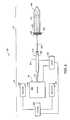
- FIG. 1depicts an exemplary injection system 10 , which includes a medical fluid injector 12 and a syringe 14 .
- the injector 12includes a substance and is designed to heat and/or cool the substance (e.g., liquid) to cause a resulting change in volume of the substance, thus causing actuation of the syringe 14 .
- the injection system 10may be substantially or entirely non-ferrous. To this end, the system 10 may include very little, if any, parts (e.g., electric motors) having ferrous material that might interfere with operation of an MRI machine.
- the injector 12includes a reservoir 16 , a heat source 18 , a heat sink 20 , a fluid conduit 22 , an actuator 24 , a sensor 26 , and a controller 28 , details of which are described below.
- the combination of the heat source 18 and the heat sink 20is one example of what may be referred to herein as a thermal device.
- Some embodiments of the injector 12may include a fluid thermo-mechanical actuator that operates as a thermal gradient and causes a fluid (e.g., liquid and/or gas) thereof to expand and/or contract to induce movement.
- Other embodiments of the injector 12may include a solid thermo-mechanical actuator that operates as a thermal gradient and causes a solid to expand and/or contract to induce movement.
- the reservoir 16 of the injector 12has walls 30 that may be made of any appropriate material.
- the walls 30may consist essentially of non-ferrous material exhibiting a high thermal conductivity, such as aluminum, stainless steel, copper, or a combination thereof.
- the walls 30may include structures that increase surface area, such as fins, rods, undulations and/or texturing. These structures may be on the inside and/or outside surfaces of the reservoir 16 .
- the walls 30preferably define a structure that is substantially rigid and substantially non-deformable with respect to forces arising from pressure differentials across the walls 30 .
- the reservoir 16may exhibit any appropriate design/configuration.
- the reservoir 16may have a rectangular cross-sectional shape, circular cross sectional shape, square cross-sectional shape, or other cross-sectional shape.
- the reservoir 16contains a fluid 32 (e.g., a liquid).
- the fluid 32may be substantially incompressible, have a phase change temperature outside of a range of temperatures to which the fluid 32 is exposed during operation of the injector, and/or have a large coefficient of thermal expansion, e.g., the coefficient of thermal expansion may be greater than 1 * 10 ⁇ 3 ° C. ⁇ 1 .
- the fluid 32may include water, alcohol, oil, mercury, or a combination thereof.
- the fluid 32may have a liquid-to-gas phase change temperature at or near a temperature of the environment in which the powered injector 12 is operated (e.g., near room temperature).
- the heat source 18is in thermal communication with the fluid 32 .
- the heat source 18may include or refer to any appropriate heat source such as a resistive heater (e.g., a coil of wire), an inductive heater, a heat pipe, a Peltier device, a heat pump, a radiant heater, a microwave source, and/or a room providing ambient heat.
- the heat source 18may be disposed outside the reservoir 16 , inside the reservoir 16 , or both outside and inside the reservoir 16 .
- the heat source 18may be configured to convert electrical energy into heat energy and heat the fluid 32 in the reservoir 16 .
- the injector 12 of FIG. 1also includes a heat sink 20 .
- the heat sink 20may include or refer to any appropriate heat sink such as a Peltier device, a refrigeration system, a heat pipe, and/or a surrounding room to absorb heat.
- the heat sink 20may be disposed inside, outside, or both inside and outside of the reservoir 30 .
- the heat sink 20 and heat source 18may be integrated into a single device.
- a thermoelectric devicesuch as a Peltier device, may heat or cool depending on whether the device is forward or reverse biased.
- a heat pumpmay operate as both a refrigeration system and a heater.
- a fluid conduit 22may connect to the reservoir 16 .
- the fluid conduit 22in some embodiments, may be the only outlet for fluid 32 from the reservoir 16 .
- the fluid conduit 22may include appropriate fittings to connect to the reservoir 16 .
- the fluid conduit 22includes substantially non-expandable tubing, such as a hydraulic line.
- the fluid conduit 22is illustrated as housing at least a portion of the fluid 32 and being connected to the actuator 24 of the injector 12 .
- the actuator 24 of the injector 12is shown as having a barrel 34 , a piston head 36 , a rod 38 , and a syringe interface 40 .
- the barrel 34may be a generally cylindrical tube with substantially rigid walls.
- the piston head 36may be described as a fluidly movable member (i.e., a member that moves in response to a difference in fluid pressure).
- the barrel 34 and the piston head 36may be cylindrical, polygonal, or any other suitable geometry.
- the barrel 34may have a diameter of about 0.4 inch (e.g., 0.375 inch) and a length of about 5.0 inches.
- the piston head 36may fit within the barrel 34 , and it may be shaped and sized to form a moveable seal against the walls of the barrel 34 .
- Fluid 32may occupy the space inside the barrel 34 on one side of the piston head 36 .
- the rod 38may extend from the piston head 36 on the side of the piston head 36 opposite the fluid 32 .
- the syringe interface 40may be disposed at the distal end of the rod 38 .
- the syringe interface 40may include a plate or surface to press against a syringe 14 or an interlocking member or device to couple to a syringe 14 , for instance.
- One or more sensors 26may be positioned to sense a variety of parameters, such as the position of the piston head 36 in the barrel 34 , the pressure of the fluid 32 , and/or the temperature of the fluid 32 .
- a linear position transducermay be attached to both a reference point (e.g., the barrel 34 ) and a moving part (e.g., the piston head 36 , the rod 38 , or the syringe interface 40 ).
- parameters of the fluid 32may be monitored by a thermocouple or pressure transducer.
- the controller 28 of the present embodimentmay include circuitry and/or code configured to modulate the position of the syringe interface 40 by signaling the heat source 18 and/or heat sink 20 to add or remove heat from the fluid 32 .
- the controller 28may include feedback circuitry or code adapted to control the position of the syringe interface 40 , the rate of movement of the syringe interface 40 , and/or the magnitude of force applied by the syringe interface 40 .
- the controller 28may have circuitry and/or code adapted to control the temperature of the fluid 32 , the rate of change of the temperature of the fluid 32 , the pressure of the fluid 32 , and/or the rate of change of the pressure of the fluid 32 .
- the circuitry and/or codemay be configured to exercise in situ or ex situ feedback or feed forward control of one or more of these parameters.
- a variety of devicesmay embody all or part of the controller 28 , such as a microprocessor, a computer, a personal computer, micro-controller, an application specific integrated circuit, a digital signal processor, and/or a central processing unit.
- the controller 28may include various forms of tangible machine readable memory, such as dynamic random access memory, flash memory, static random access memory, a hard disc drive, an optical drive, and/or a magnetic tape drive.
- the memorymay store code configured to control the powered injector 12 .
- the controller 28may also include devices to interface with the sensor 26 , the heat source 18 , and the heat sink 20 , such as an analog-to-digital converter, an amplifier circuit, and/or a driver circuit. While the controller 28 is depicted in FIG.
- FIG. 1should be regarded as depicting a logical or functional unit rather than as depicting a single device.
- the illustrated syringe 14may include a barrel 42 , a plunger 44 , and a push rod 46 .
- the barrel 42may be made of glass or plastic and have a generally cylindrical tubular shape.
- the plunger 44may be shaped to fit within the barrel 42 and slidably seal against the walls of the barrel 42 .
- the illustrated barrel 42 and plunger 44may house a medical fluid 48 , such as a liquid pharmaceutical, a liquid contrast agent, or saline, for example.
- the push rod 46may extend from a side of the plunger 44 opposite the medical fluid 48 and interface with syringe interface 40 of the actuator 24 .
- the barrel 42 of the syringe 14may be secured in fixed relation to the barrel 34 of the actuator 24 by, for instance, a chassis or frame.
- the syringe 14may be in fluid communication with a patient or organism via tubing and a hypodermic needle.
- the injection system 10may pump the medical fluid 48 into a patient, as depicted by FIGS. 1 , 2 .
- FIG. 1depicts the initiation of an injection
- FIG. 2illustrates the injection system 10 at or near the end of an injection.
- usermay signal the controller 28 to begin injecting by pressing a button, turning a dial, or otherwise indicating a desire to begin injecting the medical fluid 48 .
- the controller 28may signal the heat source 18 to apply heat energy 50 to the fluid 32 .
- the heat source 18may generate a thermal gradient between the fluid 32 and the heat source 18 , with the heat source 18 at a higher temperature.
- the controller 28may signal the heat source 18 by closing an electric current path to a resistive heater disposed in or near the fluid 32 .
- the fluid 32may expand due to thermal expansion.
- the fluid 32may expand without changing phase, e.g., the fluid 32 may remain a liquid during injection.
- the fluid 32may cause the syringe interface 40 to move, as indicated by arrow 52 .
- the expanding fluid 32may build pressure within the reservoir 16 . Some of the expanding fluid 32 may flow through the fluid conduit 22 and into the actuator 24 .
- the pressurized fluid 32may apply a force to the piston head 36 in the direction of arrow 52 . This force may drive the piston head 36 through the barrel 34 .
- the piston head 36in turn, may drive the rod 38 , which may push the syringe interface 40 .
- the syringe interface 40moves in the direction of arrow 52 , it may push the plunger 44 through the barrel 42 of the syringe 14 via the push rod 46 .
- the plunger 44may drive the medical fluid 48 out of the syringe 14 and into a patient or other organism.
- the controller 28may exercise feedback or feed forward control over a variety of parameters. For example, the controller 28 may receive feedback signals from the sensor 26 indicative of the fluid 32 temperature, the fluid 32 pressure, the position of the syringe interface 40 , the velocity of the interface 40 , the flow rate, and/or the rate of change of one or more of these parameters. In some embodiments, the controller 28 may output a signal to the heat source 18 in response to one or more of these feedback signals.
- the controller 28may control the volume of medical fluid 48 injected, the rate at which the medical fluid 48 is injected, the distance that the syringe interface 40 travels, the speed of the syringe interface 40 , the temperature of fluid 32 , the rate of change of the temperature of fluid 32 , the volume of fluid 32 , the rate of change of the volume of fluid 32 , the pressure of fluid 32 , and/or the rate of change of pressure of fluid 32 .
- the controller 28may target a set point for one or more of these parameters.
- the set point or controlled parametermay vary during injection according to a profile (e.g., velocity profile or flow rate profile) stored in memory.
- the syringe interface 40may move at a first speed for the first 10 seconds of an injection and a second, different speed, for the remainder of the injection.
- the piston head 36may have traveled through the barrel 34 of the actuator 24 , and the plunger 44 may have traveled through the barrel 42 of the syringe 14 .
- the syringe 14may have pumped a portion of the medical fluid 48 into the patient via a hypodermic needle or other device.
- the controller 28may signal the heat source 18 to stop adding heat 50 to the fluid 32 , reduce the amount of heat added to the fluid 32 , or apply heat 50 to the fluid 32 at a rate that maintains the temperature of the fluid 32 .
- the controller 28may also output a signal indicating that the injection is complete to an audio or visual indicator, such as a speaker, light emitting diode, a liquid crystal display, a cathode ray tube, an organic light emitting diode display, or the like.
- an audio or visual indicatorsuch as a speaker, light emitting diode, a liquid crystal display, a cathode ray tube, an organic light emitting diode display, or the like.
- FIG. 3depicts the powered injector 12 as the syringe 14 is reset or loaded.
- the powered injector 12may pull the syringe interface backward, as indicated by arrow 54 .
- the movement indicated by arrow 54may be initiated by a user signaling a desire to reset the powered injector or load the syringe 14 through a user interface.
- the controller 28may receive this signal and, in response, signal the heat sink 20 to cool the fluid 32 in the reservoir 16 .
- the heat sink 20may form a thermal gradient between the heat sink 20 and the fluid 32 , and heat energy 56 may flow from the fluid 32 to the heat sink 20 .
- the controller 28may close a current path to a Peltier cooler, and the Peltier cooler may accept heat from the fluid 32 .
- the fluid 32may contract and apply a negative pressure (i.e., a negative gauge pressure) to the piston head 36 .
- a negative pressurei.e., a negative gauge pressure
- the syringe interface 40may be coupled to the push rod 46 , and the syringe 14 may be loaded as the piston head 36 is drawn toward the reservoir 16 .
- the fluid conduit 22may couple to the barrel 34 or the opposite side of the piston head 36 , such that cooling causes the movement 52 and heating causes the movement 54 .
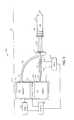
- FIG. 4depicts another exemplary injection system 58 .
- the heat source 18includes an array of resistive heating coils disposed within the reservoir 16
- the heat sink 20includes an array of Peltier coolers disposed on the exterior surface of the reservoir 16 .
- the present embodimentalso includes a reset air assist assembly 60 having a pressure vessel 62 and a gas conduit 64 .
- the gas conduit 64fluidically couples the pressure vessel 62 to the barrel 34 of the actuator 24 .
- the gas conduit 64connects to a portion of the barrel 34 that is on an opposite side of the piston head 36 relative to the fluid conduit 22 .
- pressure from the pressure vessel 62counteracts pressure from the fluid 32 .
- the piston head 36may pressurize the pressure vessel 62 as the piston head 36 is extended. Then, during loading of the syringe 14 , or resetting of the injection system 58 , the pressure from the pressure vessel 62 may drive the piston head 36 into a retracted position in the barrel 34 .
- the pressure vesselmay contain air or other appropriate compressible gas.
- FIG. 5illustrates another exemplary injection system 66 .
- the present embodimentincludes a dual-temperature injector 68 that may have dual reservoirs 16 , 70 , a reversible thermoelectric device 72 , insulation 74 , a second fluid conduit 76 , and a second body of fluid 78 .
- the thermoelectric device 72may include a Peltier-Seebeck device adapted to transfer heat energy from one reservoir 16 , 70 to the other reservoir 16 , 70 in response to a current. Further, the direction in which the thermoelectric device 72 transfers heat may depend on the direction in which current powering the thermoelectric device 72 flows. That is, current flow in a first direction may result in heat being transferred from the first reservoir 16 to the second reservoir 70 , and current flow in an opposite direction may result in heat being transferred from the second reservoir 70 to the first reservoir 16 .
- thermoelectric device 72may be disposed between and in thermal communication with the reservoirs 16 , 70 .
- the insulation 74may envelope the reservoirs 16 , 70 and the thermoelectric device 72 .
- the second fluid conduit 76may fluidically couple the second reservoir 70 to the actuator 24 . More specifically, the second fluid conduit 76 may couple to the volume of the barrel 34 opposite the piston head 36 from the fluid 32 .
- the controller 28may initiate injection by signaling the thermoelectric device 72 to transfer heat from the second reservoir 70 to the first reservoir 16 .
- the controller 28may drive a current through the thermoelectric device 70 in a first direction.
- application of heat energy to the first reservoir 16may result in the fluid 32 expanding and driving the piston head 36 forward.
- removal of heat energy from the second reservoir 70may cause the volume of fluid 78 to decrease, thereby tending to pull the piston head 36 forward.
- fluid 32pushes the piston head 36 while fluid 78 pulls it during injection.
- the controller 28may reverse the direction of the current applied to the thermoelectric device 72 .
- the thermoelectric device 72may reverse the direction in which it transfers heat, and heat energy may flow from the first reservoir 16 to the second reservoir 70 .
- the fluid 78may push the piston head 36 back through the barrel 34 , and the fluid 32 may pull the piston head 36 in the same direction.
- FIG. 6is another exemplary injection system 80 .
- the present embodimentmay include a powered injector 82 having a solid thermo-mechanical actuator 84 .
- the solid thermo-mechanical actuator 84may include shape memory alloys, shape memory polymers, or other materials with a high thermal coefficient of expansion.
- the actuator 84may be substantially or entirely non-ferrous.
- the actuator 84 and syringe 14may be secured to a chassis 86 that holds them in fixed relation.
- the heat source 18may deliver heat energy 50 to the actuator 84 , and the actuator 84 may expand.
- a currentis conducted through the actuator 84 , and internal resistive heating generates heat energy 50 .
- the actuator 84may expand, as illustrated by arrow 88 .
- the syringe interface 40may drive the plunger 44 through the barrel 42 of the syringe 14 , as depicted by arrow 52 .
- the heat sink 20may retract the actuator 84 by removing heat energy from the actuator 82 .
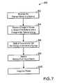
- FIG. 7is a flow chart depicting an exemplary injection process 90 , which may be performed by one or more of the previously discussed embodiments.
- the process 90begins with modulating the thermal energy of a material, as depicted by block 92 .
- Modulating the thermal energymay include transferring heat energy by conduction, convection, radiation, resistive heating, chemical heating, mechanically heating, or a combination thereof.
- modulating the thermal energymay include raising or lowering the temperature of the material.
- a change in the volume or shape of the materialis induced by the resulting change in thermal energy, as depicted by block 94 , and a force arising from the change in volume is applied to a syringe, as depicted block 96 .
- a medical fluidis injected into a patient by the syringe, as depicted by block 98 .
- Imaging the patientis imaged, as depicted by block 100 .
- Imaging the patientmay be performed with a variety of types of imaging systems, such as a projection radiography system (e.g., an x-ray system), a fluoroscopy system, a tomography system (e.g., a computed axial tomography system), a magnetic resonance imaging (MRI) system, and/or an ultrasound system, for instance.
- a projection radiography systeme.g., an x-ray system
- a fluoroscopy systeme.g., a computed axial tomography system
- MRImagnetic resonance imaging
- ultrasound systeme.g., ultrasound system, for instance.
- Certain non-ferrous embodimentsmay tend to minimize interference with MRI systems.
Landscapes
- Health & Medical Sciences (AREA)
- Vascular Medicine (AREA)
- Engineering & Computer Science (AREA)
- Anesthesiology (AREA)
- Biomedical Technology (AREA)
- Heart & Thoracic Surgery (AREA)
- Hematology (AREA)
- Life Sciences & Earth Sciences (AREA)
- Animal Behavior & Ethology (AREA)
- General Health & Medical Sciences (AREA)
- Public Health (AREA)
- Veterinary Medicine (AREA)
- Infusion, Injection, And Reservoir Apparatuses (AREA)
Abstract
Description
Claims (24)
Priority Applications (1)
| Application Number | Priority Date | Filing Date | Title |
|---|---|---|---|
| US12/439,212US8133198B2 (en) | 2006-10-26 | 2007-10-24 | Medical fluid injector having a thermo-mechanical drive |
Applications Claiming Priority (3)
| Application Number | Priority Date | Filing Date | Title |
|---|---|---|---|
| US85452906P | 2006-10-26 | 2006-10-26 | |
| US12/439,212US8133198B2 (en) | 2006-10-26 | 2007-10-24 | Medical fluid injector having a thermo-mechanical drive |
| PCT/US2007/022565WO2008057223A2 (en) | 2006-10-26 | 2007-10-24 | Medical fluid injector having a thermo-mechanical drive |
Related Parent Applications (1)
| Application Number | Title | Priority Date | Filing Date |
|---|---|---|---|
| PCT/US2007/022565A-371-Of-InternationalWO2008057223A2 (en) | 2006-10-26 | 2007-10-24 | Medical fluid injector having a thermo-mechanical drive |
Related Child Applications (1)
| Application Number | Title | Priority Date | Filing Date |
|---|---|---|---|
| US13/364,108DivisionUS8486008B2 (en) | 2006-10-26 | 2012-02-01 | Medical fluid injector having a thermo-mechanical drive |
Publications (2)
| Publication Number | Publication Date |
|---|---|
| US20100004534A1 US20100004534A1 (en) | 2010-01-07 |
| US8133198B2true US8133198B2 (en) | 2012-03-13 |
Family
ID=39364980
Family Applications (2)
| Application Number | Title | Priority Date | Filing Date |
|---|---|---|---|
| US12/439,212Expired - Fee RelatedUS8133198B2 (en) | 2006-10-26 | 2007-10-24 | Medical fluid injector having a thermo-mechanical drive |
| US13/364,108Expired - Fee RelatedUS8486008B2 (en) | 2006-10-26 | 2012-02-01 | Medical fluid injector having a thermo-mechanical drive |
Family Applications After (1)
| Application Number | Title | Priority Date | Filing Date |
|---|---|---|---|
| US13/364,108Expired - Fee RelatedUS8486008B2 (en) | 2006-10-26 | 2012-02-01 | Medical fluid injector having a thermo-mechanical drive |
Country Status (5)
| Country | Link |
|---|---|
| US (2) | US8133198B2 (en) |
| EP (2) | EP2077875A2 (en) |
| JP (2) | JP5588678B2 (en) |
| CN (2) | CN102836478B (en) |
| WO (1) | WO2008057223A2 (en) |
Cited By (9)
| Publication number | Priority date | Publication date | Assignee | Title |
|---|---|---|---|---|
| US20170224929A1 (en)* | 2014-11-18 | 2017-08-10 | Eli Lilly And Company | Thermal locking mechanism for a medication delivery device |
| US10020010B1 (en)* | 2015-11-13 | 2018-07-10 | Nutech Ventures | Near-field heat transfer enabled nanothermomechanical memory and logic devices |
| US12337160B1 (en) | 2024-04-19 | 2025-06-24 | Genzyme Corporation | Medicament delivery device |
| US12343511B1 (en) | 2024-04-19 | 2025-07-01 | Genzyme Corporation | Medicament delivery device |
| US12343505B1 (en) | 2024-04-19 | 2025-07-01 | Genzyme Corporation | Medicament delivery device |
| US12357758B1 (en)* | 2024-04-19 | 2025-07-15 | Genzyme Corporation | Medicament delivery device |
| US12377226B1 (en) | 2024-04-19 | 2025-08-05 | Genzyme Corporation | Medicament delivery device |
| US12420017B1 (en) | 2025-02-26 | 2025-09-23 | Genzyme Corporation | Damping device for a medicament delivery device |
| US12434008B1 (en) | 2025-02-26 | 2025-10-07 | Genzyme Corporation | Lock ring for a medicament delivery device |
Families Citing this family (32)
| Publication number | Priority date | Publication date | Assignee | Title |
|---|---|---|---|---|
| US6663602B2 (en) | 2000-06-16 | 2003-12-16 | Novo Nordisk A/S | Injection device |
| ATE444090T1 (en) | 2004-10-21 | 2009-10-15 | Novo Nordisk As | SELECTION MECHANISM FOR A ROTARY PIN |
| US20090043264A1 (en) | 2005-04-24 | 2009-02-12 | Novo Nordisk A/S | Injection Device |
| ATE458517T1 (en) | 2006-05-16 | 2010-03-15 | Novo Nordisk As | TRANSMISSION MECHANISM FOR AN INJECTION DEVICE |
| JP5253387B2 (en) | 2006-05-18 | 2013-07-31 | ノボ・ノルデイスク・エー/エス | Injection device with mode locking means |
| US9108006B2 (en) | 2007-08-17 | 2015-08-18 | Novo Nordisk A/S | Medical device with value sensor |
| CA2707820A1 (en)* | 2007-12-31 | 2009-07-09 | Novo Nordisk A/S | Electronically monitored injection device |
| JP6150523B2 (en)* | 2010-02-05 | 2017-06-21 | デカ・プロダクツ・リミテッド・パートナーシップ | Infusion pump apparatus, method and system |
| WO2012077129A2 (en)* | 2010-12-06 | 2012-06-14 | Sujoy Kumar Guha | Auto-destruct, pre-loaded syringe |
| JP6069351B2 (en) | 2011-12-29 | 2017-02-01 | ノボ・ノルデイスク・エー/エス | Torsion spring type automatic syringe with dial-up / dial-down administration mechanism |
| ITRM20130076A1 (en)* | 2013-02-12 | 2014-08-13 | Gianfranco Cappello | INFUSION PUMP TO INFUSE A PATIENT WITH WATER AND NOT WATER SOLUTIONS, IN NON-HOMOGENEOUS DETAILS. |
| WO2014195489A1 (en)* | 2013-06-07 | 2014-12-11 | Kebomed Ag | A device for thermal ablation |
| MX382643B (en) | 2013-12-30 | 2025-03-11 | Phi Tech Animal Health Tech Ltd | INJECTION DEVICES. |
| WO2017089255A1 (en) | 2015-11-27 | 2017-06-01 | Sanofi-Aventis Deutschland Gmbh | An auto-injector device |
| IL242942A0 (en)* | 2015-12-03 | 2016-04-21 | Gershon Goldenberg | Thermal control of liquids for transcutaneous delivery |
| CN105999467A (en)* | 2016-05-16 | 2016-10-12 | 江苏微全芯生物科技有限公司 | Injection pump and multichannel injection system as well as operating methods thereof |
| EP3468478B1 (en)* | 2016-06-09 | 2025-02-12 | C. R. Bard, Inc. | Systems for correcting and preventing occlusion in a catheter |
| FR3064919B1 (en) | 2017-04-10 | 2020-07-10 | Aptar France Sas | DEVICE FOR AUTOMATIC INJECTION OF FLUID PRODUCT. |
| IL270247B2 (en) | 2017-05-01 | 2023-10-01 | Phi Tech Animal Health Tech Ltd | Injection apparatus and method for use |
| WO2019116229A1 (en) | 2017-12-11 | 2019-06-20 | Target Point Technologies Ltd. | Intranasal administration device |
| CN111491562A (en)* | 2017-12-15 | 2020-08-04 | 皇家飞利浦有限公司 | Wearable or insertable device with microneedles comprising mechanically responsive material |
| CN109821112B (en)* | 2019-03-01 | 2021-03-02 | 浙江师范大学 | A piezoelectric stack-driven medicinal liquid bolus device |
| CN109821102B (en)* | 2019-03-01 | 2021-04-30 | 浙江师范大学 | Gas step-by-step compression driven dosing device |
| CN109876239B (en)* | 2019-03-01 | 2021-03-16 | 浙江师范大学 | Piezoelectric sheet driven injection system |
| CN109821099B (en)* | 2019-03-01 | 2021-04-30 | 浙江师范大学 | Inflatable extrusion type infusion device |
| CN109771739B (en)* | 2019-03-01 | 2021-02-26 | 浙江师范大学 | Piezoelectric piece driven medicine injector |
| CN109821097B (en)* | 2019-03-01 | 2021-04-30 | 浙江师范大学 | Gaseous extrusion formula infusion set |
| CN109821103B (en)* | 2019-03-01 | 2021-02-26 | 浙江师范大学 | Piezoelectric stack driven injection system |
| US20200330703A1 (en)* | 2019-04-22 | 2020-10-22 | Matthew Carl Mosher | System for maintaining temperature of liquid medicine |
| CN110037825B (en)* | 2019-06-05 | 2020-11-13 | 北京首农未来生物科技有限公司 | Artificial insemination system for assisting animal reproduction |
| CN111084915A (en)* | 2019-12-31 | 2020-05-01 | 无锡物联网创新中心有限公司 | Micro-power injection device and batching equipment |
| CN114082047A (en)* | 2021-12-03 | 2022-02-25 | 南方医科大学南方医院 | Painless electric skin injection device |
Citations (14)
| Publication number | Priority date | Publication date | Assignee | Title |
|---|---|---|---|---|
| US4070859A (en)* | 1976-12-23 | 1978-01-31 | Design & Manufacturing Corporation | Thermal fluid displacement actuator |
| US4121425A (en)* | 1976-06-14 | 1978-10-24 | Nicodemus Carl D | Thermodynamic system |
| EP0232164A2 (en) | 1986-02-04 | 1987-08-12 | Brunel University | Movement control device and syringe |
| US4861340A (en) | 1988-10-17 | 1989-08-29 | Cordis Corporation | Hand-held pneumatic power assisted syringe |
| US4944726A (en) | 1988-11-03 | 1990-07-31 | Applied Vascular Devices | Device for power injection of fluids |
| EP0385916A2 (en) | 1989-02-24 | 1990-09-05 | S.I. Scientific Innovations Ltd. | Device for dispensing a liquid particularly useful for delivering medicaments at a predetermined rate. |
| US5197322A (en) | 1990-11-29 | 1993-03-30 | Minimed Technologies, Ltd. | Pressure reservoir filling process for an implantable medication infusion pump |
| US5505706A (en) | 1989-01-10 | 1996-04-09 | Maus; Daryl D. | Heat-activated drug delivery system and thermal actuators therefor |
| US5571261A (en) | 1993-08-06 | 1996-11-05 | River Medical, Inc | Liquid delivery device |
| WO2001072357A2 (en) | 2000-03-29 | 2001-10-04 | Minimed, Inc. | Improved methods, apparatuses, and uses for infusion pump fluid pressure and force detection |
| US20020156418A1 (en) | 2000-11-30 | 2002-10-24 | Gonnelli Robert R. | Injection systems |
| US20040115068A1 (en) | 2002-09-27 | 2004-06-17 | Steffen Hansen | Membrane pump with stretchable pump membrane |
| EP1570875A1 (en) | 2004-03-04 | 2005-09-07 | Roche Diagnostics GmbH | Pyrotechnically driven needle-free liquid jet injection device with low-cost components and production |
| US20080287873A1 (en)* | 2007-04-13 | 2008-11-20 | Aldo Liberatore | Method and apparatus for controlling operation of a syringe |
Family Cites Families (7)
| Publication number | Priority date | Publication date | Assignee | Title |
|---|---|---|---|---|
| US5081358A (en)* | 1990-02-23 | 1992-01-14 | Shimadzu Corporation | Detector of fourier transform infrared spectrometer |
| JPH05231302A (en)* | 1992-02-25 | 1993-09-07 | Yaskawa Electric Corp | Piston pump |
| US5269762A (en)* | 1992-04-21 | 1993-12-14 | Sterling Winthrop, Inc. | Portable hand-held power assister device |
| JPH08150205A (en)* | 1994-11-30 | 1996-06-11 | Olympus Optical Co Ltd | Treating device for injecting injectant |
| US5868710A (en)* | 1996-11-22 | 1999-02-09 | Liebel Flarsheim Company | Medical fluid injector |
| JPH11324902A (en)* | 1998-05-06 | 1999-11-26 | Kitz Corp | Electro thermal actuator, valve and pump |
| US7374565B2 (en)* | 2004-05-28 | 2008-05-20 | Ethicon Endo-Surgery, Inc. | Bi-directional infuser pump with volume braking for hydraulically controlling an adjustable gastric band |
- 2007
- 2007-10-24WOPCT/US2007/022565patent/WO2008057223A2/enactiveApplication Filing
- 2007-10-24USUS12/439,212patent/US8133198B2/ennot_activeExpired - Fee Related
- 2007-10-24JPJP2009534637Apatent/JP5588678B2/ennot_activeExpired - Fee Related
- 2007-10-24CNCN201210349967.1Apatent/CN102836478B/ennot_activeExpired - Fee Related
- 2007-10-24EPEP07839781Apatent/EP2077875A2/ennot_activeWithdrawn
- 2007-10-24EPEP09006075Apatent/EP2087917A1/ennot_activeWithdrawn
- 2007-10-24CNCN2007800397160Apatent/CN101528285B/ennot_activeExpired - Fee Related
- 2012
- 2012-02-01USUS13/364,108patent/US8486008B2/ennot_activeExpired - Fee Related
- 2013
- 2013-09-02JPJP2013181099Apatent/JP2013236970A/ennot_activeWithdrawn
Patent Citations (15)
| Publication number | Priority date | Publication date | Assignee | Title |
|---|---|---|---|---|
| US4121425A (en)* | 1976-06-14 | 1978-10-24 | Nicodemus Carl D | Thermodynamic system |
| US4070859A (en)* | 1976-12-23 | 1978-01-31 | Design & Manufacturing Corporation | Thermal fluid displacement actuator |
| EP0232164A2 (en) | 1986-02-04 | 1987-08-12 | Brunel University | Movement control device and syringe |
| US4861340A (en) | 1988-10-17 | 1989-08-29 | Cordis Corporation | Hand-held pneumatic power assisted syringe |
| US4944726A (en) | 1988-11-03 | 1990-07-31 | Applied Vascular Devices | Device for power injection of fluids |
| US5505706A (en) | 1989-01-10 | 1996-04-09 | Maus; Daryl D. | Heat-activated drug delivery system and thermal actuators therefor |
| US5062834A (en) | 1989-02-24 | 1991-11-05 | Product Development (S.G.Z.) Ltd | Device for dispensing a liquid particularly useful for delivering medicaments at a predetermined rate |
| EP0385916A2 (en) | 1989-02-24 | 1990-09-05 | S.I. Scientific Innovations Ltd. | Device for dispensing a liquid particularly useful for delivering medicaments at a predetermined rate. |
| US5197322A (en) | 1990-11-29 | 1993-03-30 | Minimed Technologies, Ltd. | Pressure reservoir filling process for an implantable medication infusion pump |
| US5571261A (en) | 1993-08-06 | 1996-11-05 | River Medical, Inc | Liquid delivery device |
| WO2001072357A2 (en) | 2000-03-29 | 2001-10-04 | Minimed, Inc. | Improved methods, apparatuses, and uses for infusion pump fluid pressure and force detection |
| US20020156418A1 (en) | 2000-11-30 | 2002-10-24 | Gonnelli Robert R. | Injection systems |
| US20040115068A1 (en) | 2002-09-27 | 2004-06-17 | Steffen Hansen | Membrane pump with stretchable pump membrane |
| EP1570875A1 (en) | 2004-03-04 | 2005-09-07 | Roche Diagnostics GmbH | Pyrotechnically driven needle-free liquid jet injection device with low-cost components and production |
| US20080287873A1 (en)* | 2007-04-13 | 2008-11-20 | Aldo Liberatore | Method and apparatus for controlling operation of a syringe |
Cited By (10)
| Publication number | Priority date | Publication date | Assignee | Title |
|---|---|---|---|---|
| US20170224929A1 (en)* | 2014-11-18 | 2017-08-10 | Eli Lilly And Company | Thermal locking mechanism for a medication delivery device |
| US10314981B2 (en)* | 2014-11-18 | 2019-06-11 | Eli Lilly And Company | Thermal locking mechanism for a medication delivery device |
| US10020010B1 (en)* | 2015-11-13 | 2018-07-10 | Nutech Ventures | Near-field heat transfer enabled nanothermomechanical memory and logic devices |
| US12337160B1 (en) | 2024-04-19 | 2025-06-24 | Genzyme Corporation | Medicament delivery device |
| US12343511B1 (en) | 2024-04-19 | 2025-07-01 | Genzyme Corporation | Medicament delivery device |
| US12343505B1 (en) | 2024-04-19 | 2025-07-01 | Genzyme Corporation | Medicament delivery device |
| US12357758B1 (en)* | 2024-04-19 | 2025-07-15 | Genzyme Corporation | Medicament delivery device |
| US12377226B1 (en) | 2024-04-19 | 2025-08-05 | Genzyme Corporation | Medicament delivery device |
| US12420017B1 (en) | 2025-02-26 | 2025-09-23 | Genzyme Corporation | Damping device for a medicament delivery device |
| US12434008B1 (en) | 2025-02-26 | 2025-10-07 | Genzyme Corporation | Lock ring for a medicament delivery device |
Also Published As
| Publication number | Publication date |
|---|---|
| CN102836478B (en) | 2015-03-11 |
| CN102836478A (en) | 2012-12-26 |
| CN101528285A (en) | 2009-09-09 |
| EP2077875A2 (en) | 2009-07-15 |
| CN101528285B (en) | 2012-10-31 |
| WO2008057223A3 (en) | 2008-08-21 |
| EP2087917A1 (en) | 2009-08-12 |
| JP5588678B2 (en) | 2014-09-10 |
| US20120130237A1 (en) | 2012-05-24 |
| US8486008B2 (en) | 2013-07-16 |
| WO2008057223A2 (en) | 2008-05-15 |
| JP2013236970A (en) | 2013-11-28 |
| JP2010507450A (en) | 2010-03-11 |
| US20100004534A1 (en) | 2010-01-07 |
Similar Documents
| Publication | Publication Date | Title |
|---|---|---|
| US8133198B2 (en) | Medical fluid injector having a thermo-mechanical drive | |
| US20060271014A1 (en) | Heat retention device for a syringe and methods of use | |
| US10543312B2 (en) | Fluid delivery system and method of fluid delivery to a patient | |
| CN101583797B (en) | Wax micro actuator | |
| US7632245B1 (en) | Devices, systems and methods for delivery of a fluid into a patient during a magnetic resonance procedure | |
| CN105641776B (en) | Liquid medicine injection system, liquid medicine injection device and liquid medicine heat preservation device | |
| US8630694B2 (en) | Medical imaging system and fluid-driven injector | |
| JP5809471B2 (en) | System and method for operation of a magnetic resonance imaging system during ramping | |
| US11602591B2 (en) | Cartridge-based in-bore infuser | |
| JP2009050289A (en) | Method of sucking medicinal liquid, automatic suction machine and automatic injection machine | |
| US7922694B2 (en) | Drive device for a piston in a container containing a liquid product | |
| JP2009039311A (en) | Chemical injection device | |
| US20170007760A1 (en) | Injection device |
Legal Events
| Date | Code | Title | Description |
|---|---|---|---|
| AS | Assignment | Owner name:MALLINCKRODT INC., MISSOURI Free format text:ASSIGNMENT OF ASSIGNORS INTEREST;ASSIGNOR:NEER, CHARLES S.;REEL/FRAME:022322/0102 Effective date:20061128 | |
| AS | Assignment | Owner name:MALLINCKRODT LLC, MISSOURI Free format text:CHANGE OF LEGAL ENTITY;ASSIGNOR:MALLINCKRODT INC.;REEL/FRAME:026754/0001 Effective date:20110623 | |
| STCF | Information on status: patent grant | Free format text:PATENTED CASE | |
| AS | Assignment | Owner name:DEUTSCHE BANK AG NEW YORK BRANCH, NEW YORK Free format text:SECURITY INTEREST;ASSIGNORS:MALLINCKRODT INTERNATIONAL FINANCE S.A.;MALLINCKRODT CB LLC;MALLINCKRODT FINANCE GMBH;AND OTHERS;REEL/FRAME:032480/0001 Effective date:20140319 | |
| AS | Assignment | Owner name:LIEBEL-FLARSHEIM COMPANY LLC, MISSOURI Free format text:ASSIGNMENT OF ASSIGNORS INTEREST;ASSIGNOR:MALLINCKRODT LLC;REEL/FRAME:034715/0531 Effective date:20140630 | |
| FPAY | Fee payment | Year of fee payment:4 | |
| AS | Assignment | Owner name:LIEBEL-FLARSHEIM COMPANY LLC, OHIO Free format text:RELEASE BY SECURED PARTY;ASSIGNOR:DEUTSCHE BANK AG NEW YORK BRANCH, AS COLLATERAL AGENT;REEL/FRAME:037172/0094 Effective date:20151127 | |
| FEPP | Fee payment procedure | Free format text:MAINTENANCE FEE REMINDER MAILED (ORIGINAL EVENT CODE: REM.); ENTITY STATUS OF PATENT OWNER: LARGE ENTITY | |
| LAPS | Lapse for failure to pay maintenance fees | Free format text:PATENT EXPIRED FOR FAILURE TO PAY MAINTENANCE FEES (ORIGINAL EVENT CODE: EXP.); ENTITY STATUS OF PATENT OWNER: LARGE ENTITY | |
| STCH | Information on status: patent discontinuation | Free format text:PATENT EXPIRED DUE TO NONPAYMENT OF MAINTENANCE FEES UNDER 37 CFR 1.362 | |
| FP | Lapsed due to failure to pay maintenance fee | Effective date:20200313 | |
| AS | Assignment | Owner name:INO THERAPEUTICS LLC, MISSOURI Free format text:RELEASE OF PATENT SECURITY INTERESTS RECORDED AT REEL 032480, FRAME 0001;ASSIGNOR:DEUTSCHE BANK AG NEW YORK BRANCH, AS COLLATERAL AGENT;REEL/FRAME:065609/0322 Effective date:20231114 Owner name:IKARIA THERAPEUTICS LLC, NEW JERSEY Free format text:RELEASE OF PATENT SECURITY INTERESTS RECORDED AT REEL 032480, FRAME 0001;ASSIGNOR:DEUTSCHE BANK AG NEW YORK BRANCH, AS COLLATERAL AGENT;REEL/FRAME:065609/0322 Effective date:20231114 Owner name:THERAKOS, INC., MISSOURI Free format text:RELEASE OF PATENT SECURITY INTERESTS RECORDED AT REEL 032480, FRAME 0001;ASSIGNOR:DEUTSCHE BANK AG NEW YORK BRANCH, AS COLLATERAL AGENT;REEL/FRAME:065609/0322 Effective date:20231114 Owner name:ST SHARED SERVICES LLC, MISSOURI Free format text:RELEASE OF PATENT SECURITY INTERESTS RECORDED AT REEL 032480, FRAME 0001;ASSIGNOR:DEUTSCHE BANK AG NEW YORK BRANCH, AS COLLATERAL AGENT;REEL/FRAME:065609/0322 Effective date:20231114 Owner name:INFACARE PHARMACEUTICAL CORPORATION, MISSOURI Free format text:RELEASE OF PATENT SECURITY INTERESTS RECORDED AT REEL 032480, FRAME 0001;ASSIGNOR:DEUTSCHE BANK AG NEW YORK BRANCH, AS COLLATERAL AGENT;REEL/FRAME:065609/0322 Effective date:20231114 Owner name:MALLINCKRODT PHARMA IP TRADING UNLIMITED COMPANY (F/K/A MALLINCKRODT PHARMA IP TRADING D.A.C.), IRELAND Free format text:RELEASE OF PATENT SECURITY INTERESTS RECORDED AT REEL 032480, FRAME 0001;ASSIGNOR:DEUTSCHE BANK AG NEW YORK BRANCH, AS COLLATERAL AGENT;REEL/FRAME:065609/0322 Effective date:20231114 Owner name:MALLINCKRODT PHARMACEUTICALS IRELAND LIMITED, IRELAND Free format text:RELEASE OF PATENT SECURITY INTERESTS RECORDED AT REEL 032480, FRAME 0001;ASSIGNOR:DEUTSCHE BANK AG NEW YORK BRANCH, AS COLLATERAL AGENT;REEL/FRAME:065609/0322 Effective date:20231114 Owner name:VTESSE LLC (F/K/A VTESSE INC.), MISSOURI Free format text:RELEASE OF PATENT SECURITY INTERESTS RECORDED AT REEL 032480, FRAME 0001;ASSIGNOR:DEUTSCHE BANK AG NEW YORK BRANCH, AS COLLATERAL AGENT;REEL/FRAME:065609/0322 Effective date:20231114 Owner name:SUCAMPO PHARMA AMERICAS LLC, MISSOURI Free format text:RELEASE OF PATENT SECURITY INTERESTS RECORDED AT REEL 032480, FRAME 0001;ASSIGNOR:DEUTSCHE BANK AG NEW YORK BRANCH, AS COLLATERAL AGENT;REEL/FRAME:065609/0322 Effective date:20231114 Owner name:STRATATECH CORPORATION, WISCONSIN Free format text:RELEASE OF PATENT SECURITY INTERESTS RECORDED AT REEL 032480, FRAME 0001;ASSIGNOR:DEUTSCHE BANK AG NEW YORK BRANCH, AS COLLATERAL AGENT;REEL/FRAME:065609/0322 Effective date:20231114 Owner name:SPECGX LLC, MISSOURI Free format text:RELEASE OF PATENT SECURITY INTERESTS RECORDED AT REEL 032480, FRAME 0001;ASSIGNOR:DEUTSCHE BANK AG NEW YORK BRANCH, AS COLLATERAL AGENT;REEL/FRAME:065609/0322 Effective date:20231114 Owner name:OCERA THERAPEUTICS LLC (F/K/A OCERA THERAPEUTICS, INC.), MISSOURI Free format text:RELEASE OF PATENT SECURITY INTERESTS RECORDED AT REEL 032480, FRAME 0001;ASSIGNOR:DEUTSCHE BANK AG NEW YORK BRANCH, AS COLLATERAL AGENT;REEL/FRAME:065609/0322 Effective date:20231114 Owner name:MALLINCKRODT ARD IP UNLIMITED COMPANY (F/K/A MALLINCKRODT ARD IP LIMITED), IRELAND Free format text:RELEASE OF PATENT SECURITY INTERESTS RECORDED AT REEL 032480, FRAME 0001;ASSIGNOR:DEUTSCHE BANK AG NEW YORK BRANCH, AS COLLATERAL AGENT;REEL/FRAME:065609/0322 Effective date:20231114 Owner name:MALLINCKRODT HOSPITAL PRODUCTS IP UNLIMITED COMPANY (F/K/A MALLINCKRODT HOSPITAL PRODUCTS IP LIMITED), IRELAND Free format text:RELEASE OF PATENT SECURITY INTERESTS RECORDED AT REEL 032480, FRAME 0001;ASSIGNOR:DEUTSCHE BANK AG NEW YORK BRANCH, AS COLLATERAL AGENT;REEL/FRAME:065609/0322 Effective date:20231114 Owner name:MEH, INC., MISSOURI Free format text:RELEASE OF PATENT SECURITY INTERESTS RECORDED AT REEL 032480, FRAME 0001;ASSIGNOR:DEUTSCHE BANK AG NEW YORK BRANCH, AS COLLATERAL AGENT;REEL/FRAME:065609/0322 Effective date:20231114 Owner name:IMC EXPLORATION COMPANY, MISSOURI Free format text:RELEASE OF PATENT SECURITY INTERESTS RECORDED AT REEL 032480, FRAME 0001;ASSIGNOR:DEUTSCHE BANK AG NEW YORK BRANCH, AS COLLATERAL AGENT;REEL/FRAME:065609/0322 Effective date:20231114 Owner name:MALLINCKRODT US HOLDINGS LLC, MISSOURI Free format text:RELEASE OF PATENT SECURITY INTERESTS RECORDED AT REEL 032480, FRAME 0001;ASSIGNOR:DEUTSCHE BANK AG NEW YORK BRANCH, AS COLLATERAL AGENT;REEL/FRAME:065609/0322 Effective date:20231114 Owner name:MALLINCKRODT VETERINARY, INC., MISSOURI Free format text:RELEASE OF PATENT SECURITY INTERESTS RECORDED AT REEL 032480, FRAME 0001;ASSIGNOR:DEUTSCHE BANK AG NEW YORK BRANCH, AS COLLATERAL AGENT;REEL/FRAME:065609/0322 Effective date:20231114 Owner name:MALLINCKRODT BRAND PHARMACEUTICALS LLC (F/K/A MALLINCKRODT BRAND PHARMACEUTICALS, INC.), MISSOURI Free format text:RELEASE OF PATENT SECURITY INTERESTS RECORDED AT REEL 032480, FRAME 0001;ASSIGNOR:DEUTSCHE BANK AG NEW YORK BRANCH, AS COLLATERAL AGENT;REEL/FRAME:065609/0322 Effective date:20231114 Owner name:LIEBEL-FLARSHEIM COMPANY LLC, MISSOURI Free format text:RELEASE OF PATENT SECURITY INTERESTS RECORDED AT REEL 032480, FRAME 0001;ASSIGNOR:DEUTSCHE BANK AG NEW YORK BRANCH, AS COLLATERAL AGENT;REEL/FRAME:065609/0322 Effective date:20231114 Owner name:LAFAYETTE PHARMACEUTICALS LLC, MISSOURI Free format text:RELEASE OF PATENT SECURITY INTERESTS RECORDED AT REEL 032480, FRAME 0001;ASSIGNOR:DEUTSCHE BANK AG NEW YORK BRANCH, AS COLLATERAL AGENT;REEL/FRAME:065609/0322 Effective date:20231114 Owner name:MALLINCKRODT LLC, MISSOURI Free format text:RELEASE OF PATENT SECURITY INTERESTS RECORDED AT REEL 032480, FRAME 0001;ASSIGNOR:DEUTSCHE BANK AG NEW YORK BRANCH, AS COLLATERAL AGENT;REEL/FRAME:065609/0322 Effective date:20231114 Owner name:MALLINCKRODT ENTERPRISES LLC, MISSOURI Free format text:RELEASE OF PATENT SECURITY INTERESTS RECORDED AT REEL 032480, FRAME 0001;ASSIGNOR:DEUTSCHE BANK AG NEW YORK BRANCH, AS COLLATERAL AGENT;REEL/FRAME:065609/0322 Effective date:20231114 Owner name:MALLINCKRODT ENTERPRISES HOLDINGS LLC (F/K/A MALLINCKRODT ENTERPRISES HOLDINGS, INC.), MISSOURI Free format text:RELEASE OF PATENT SECURITY INTERESTS RECORDED AT REEL 032480, FRAME 0001;ASSIGNOR:DEUTSCHE BANK AG NEW YORK BRANCH, AS COLLATERAL AGENT;REEL/FRAME:065609/0322 Effective date:20231114 Owner name:CNS THERAPEUTICS, INC., MISSOURI Free format text:RELEASE OF PATENT SECURITY INTERESTS RECORDED AT REEL 032480, FRAME 0001;ASSIGNOR:DEUTSCHE BANK AG NEW YORK BRANCH, AS COLLATERAL AGENT;REEL/FRAME:065609/0322 Effective date:20231114 Owner name:LUDLOW LLC (F/K/A LUDLOW CORPORATION), MISSOURI Free format text:RELEASE OF PATENT SECURITY INTERESTS RECORDED AT REEL 032480, FRAME 0001;ASSIGNOR:DEUTSCHE BANK AG NEW YORK BRANCH, AS COLLATERAL AGENT;REEL/FRAME:065609/0322 Effective date:20231114 Owner name:MNK 2011 LLC (F/K/A MALLINCKRODT INC.), MISSOURI Free format text:RELEASE OF PATENT SECURITY INTERESTS RECORDED AT REEL 032480, FRAME 0001;ASSIGNOR:DEUTSCHE BANK AG NEW YORK BRANCH, AS COLLATERAL AGENT;REEL/FRAME:065609/0322 Effective date:20231114 Owner name:MALLINCKRODT US POOL LLC, MISSOURI Free format text:RELEASE OF PATENT SECURITY INTERESTS RECORDED AT REEL 032480, FRAME 0001;ASSIGNOR:DEUTSCHE BANK AG NEW YORK BRANCH, AS COLLATERAL AGENT;REEL/FRAME:065609/0322 Effective date:20231114 Owner name:MALLINCKRODT CARRIBEAN, INC., MISSOURI Free format text:RELEASE OF PATENT SECURITY INTERESTS RECORDED AT REEL 032480, FRAME 0001;ASSIGNOR:DEUTSCHE BANK AG NEW YORK BRANCH, AS COLLATERAL AGENT;REEL/FRAME:065609/0322 Effective date:20231114 Owner name:MALLINCKRODT US HOLDINGS LLC (F/K/A MALLINCKRODT US HOLDINGS INC.), MISSOURI Free format text:RELEASE OF PATENT SECURITY INTERESTS RECORDED AT REEL 032480, FRAME 0001;ASSIGNOR:DEUTSCHE BANK AG NEW YORK BRANCH, AS COLLATERAL AGENT;REEL/FRAME:065609/0322 Effective date:20231114 Owner name:MALLINCKRODT FINANCE GMBH, SWITZERLAND Free format text:RELEASE OF PATENT SECURITY INTERESTS RECORDED AT REEL 032480, FRAME 0001;ASSIGNOR:DEUTSCHE BANK AG NEW YORK BRANCH, AS COLLATERAL AGENT;REEL/FRAME:065609/0322 Effective date:20231114 Owner name:MALLINCKRODT CB LLC, MISSOURI Free format text:RELEASE OF PATENT SECURITY INTERESTS RECORDED AT REEL 032480, FRAME 0001;ASSIGNOR:DEUTSCHE BANK AG NEW YORK BRANCH, AS COLLATERAL AGENT;REEL/FRAME:065609/0322 Effective date:20231114 Owner name:MALLINCKRODT INTERNATIONAL FINANCE S.A., LUXEMBOURG Free format text:RELEASE OF PATENT SECURITY INTERESTS RECORDED AT REEL 032480, FRAME 0001;ASSIGNOR:DEUTSCHE BANK AG NEW YORK BRANCH, AS COLLATERAL AGENT;REEL/FRAME:065609/0322 Effective date:20231114 |