US8133128B2 - Golf club head and system - Google Patents
Golf club head and systemDownload PDFInfo
- Publication number
- US8133128B2 US8133128B2US12/192,402US19240208AUS8133128B2US 8133128 B2US8133128 B2US 8133128B2US 19240208 AUS19240208 AUS 19240208AUS 8133128 B2US8133128 B2US 8133128B2
- Authority
- US
- United States
- Prior art keywords
- body member
- golf club
- club head
- rear body
- front body
- Prior art date
- Legal status (The legal status is an assumption and is not a legal conclusion. Google has not performed a legal analysis and makes no representation as to the accuracy of the status listed.)
- Active
Links
Images


Classifications
- A—HUMAN NECESSITIES
- A63—SPORTS; GAMES; AMUSEMENTS
- A63B—APPARATUS FOR PHYSICAL TRAINING, GYMNASTICS, SWIMMING, CLIMBING, OR FENCING; BALL GAMES; TRAINING EQUIPMENT
- A63B53/00—Golf clubs
- A63B53/04—Heads
- A63B53/0466—Heads wood-type
- A—HUMAN NECESSITIES
- A63—SPORTS; GAMES; AMUSEMENTS
- A63B—APPARATUS FOR PHYSICAL TRAINING, GYMNASTICS, SWIMMING, CLIMBING, OR FENCING; BALL GAMES; TRAINING EQUIPMENT
- A63B53/00—Golf clubs
- A63B53/04—Heads
- A—HUMAN NECESSITIES
- A63—SPORTS; GAMES; AMUSEMENTS
- A63B—APPARATUS FOR PHYSICAL TRAINING, GYMNASTICS, SWIMMING, CLIMBING, OR FENCING; BALL GAMES; TRAINING EQUIPMENT
- A63B53/00—Golf clubs
- A63B53/04—Heads
- A63B53/0416—Heads having an impact surface provided by a face insert
- A—HUMAN NECESSITIES
- A63—SPORTS; GAMES; AMUSEMENTS
- A63B—APPARATUS FOR PHYSICAL TRAINING, GYMNASTICS, SWIMMING, CLIMBING, OR FENCING; BALL GAMES; TRAINING EQUIPMENT
- A63B53/00—Golf clubs
- A63B53/04—Heads
- A63B53/0437—Heads with special crown configurations
- A—HUMAN NECESSITIES
- A63—SPORTS; GAMES; AMUSEMENTS
- A63B—APPARATUS FOR PHYSICAL TRAINING, GYMNASTICS, SWIMMING, CLIMBING, OR FENCING; BALL GAMES; TRAINING EQUIPMENT
- A63B60/00—Details or accessories of golf clubs, bats, rackets or the like
- A—HUMAN NECESSITIES
- A63—SPORTS; GAMES; AMUSEMENTS
- A63B—APPARATUS FOR PHYSICAL TRAINING, GYMNASTICS, SWIMMING, CLIMBING, OR FENCING; BALL GAMES; TRAINING EQUIPMENT
- A63B60/00—Details or accessories of golf clubs, bats, rackets or the like
- A63B60/02—Ballast means for adjusting the centre of mass
- A—HUMAN NECESSITIES
- A63—SPORTS; GAMES; AMUSEMENTS
- A63B—APPARATUS FOR PHYSICAL TRAINING, GYMNASTICS, SWIMMING, CLIMBING, OR FENCING; BALL GAMES; TRAINING EQUIPMENT
- A63B53/00—Golf clubs
- A63B53/04—Heads
- A63B2053/0491—Heads with added weights, e.g. changeable, replaceable
- A—HUMAN NECESSITIES
- A63—SPORTS; GAMES; AMUSEMENTS
- A63B—APPARATUS FOR PHYSICAL TRAINING, GYMNASTICS, SWIMMING, CLIMBING, OR FENCING; BALL GAMES; TRAINING EQUIPMENT
- A63B2209/00—Characteristics of used materials
- A63B2209/02—Characteristics of used materials with reinforcing fibres, e.g. carbon, polyamide fibres
- A63B2209/023—Long, oriented fibres, e.g. wound filaments, woven fabrics, mats
- A—HUMAN NECESSITIES
- A63—SPORTS; GAMES; AMUSEMENTS
- A63B—APPARATUS FOR PHYSICAL TRAINING, GYMNASTICS, SWIMMING, CLIMBING, OR FENCING; BALL GAMES; TRAINING EQUIPMENT
- A63B2209/00—Characteristics of used materials
- A63B2209/10—Characteristics of used materials with adhesive type surfaces, i.e. hook and loop-type fastener
- A—HUMAN NECESSITIES
- A63—SPORTS; GAMES; AMUSEMENTS
- A63B—APPARATUS FOR PHYSICAL TRAINING, GYMNASTICS, SWIMMING, CLIMBING, OR FENCING; BALL GAMES; TRAINING EQUIPMENT
- A63B53/00—Golf clubs
- A63B53/04—Heads
- A63B53/0433—Heads with special sole configurations
- A—HUMAN NECESSITIES
- A63—SPORTS; GAMES; AMUSEMENTS
- A63B—APPARATUS FOR PHYSICAL TRAINING, GYMNASTICS, SWIMMING, CLIMBING, OR FENCING; BALL GAMES; TRAINING EQUIPMENT
- A63B53/00—Golf clubs
- A63B53/04—Heads
- A63B53/06—Heads adjustable
Definitions
- the present inventionrelates to golf club heads, and in particular, to a golf club head system including various interchangeable parts for providing a customer specific golf club head.
- woodLonger distance golf clubs or drivers traditionally had heads made of wood (and were sometimes referred to as “woods”). However, wood, being a natural material, may be subject to unwanted variations or defects, and further requires a great deal of effort and expense to shape properly.
- metal woodshave been formed with a metallic strike face portion and a non-metallic or partially non-metallic aft body portion.
- a metallic strike face portionand a non-metallic or partially non-metallic aft body portion.
- the overall dimensions of the club headscould be increased while maintaining the same head weight. This allowed the heads of metal woods to be designed with increased striking surface area and increased moment of inertia characteristics.
- an individualswings the golf club such that the golf club head travels through a generally arcuate path.
- a portion of the inertia of golf club, and particularly the inertia of golf club headis transferred to the golf ball, thereby propelling the golf ball (hopefully) toward an intended target.
- the position of a center of gravity of the head and the club head's path toward the ballhave an influence upon whether the golf ball curves right, curves left, or follows a generally straight route. More specifically, the golf ball follows a generally straight route when the center of gravity is positioned behind the point of engagement of the ball with the striking plate and when the club head is traveling toward the intended target at the moment of impact with the ball.
- the golf ballmay follow a route that curves left or right.
- the offset of the center of gravity of the golf club head above or below (or closer to or farther away from) the point of engagementhas an influence upon whether the golf ball exhibits a boring or a climbing trajectory.
- the center of gravity (or center of mass) of a golf club headis defined as an equilibrium point, i.e., a point at which the entire weight of the golf club head may be considered as concentrated so that, if supported at that point, the golf club head would remain in static equilibrium in any position.
- aft body portionmay be customized with a plurality of weights strategically placed within or on the aft body portion so as to vary the center of gravity and/or the moments of inertia of the golf club head.
- Various aft bodiesmay be pre-manufactured and available for later, final assembly with a specific golf club face.
- a golfer's swingcould be analyzed and the golf club could be, at least partially, customized to account for various imperfections or foibles in the individual golfer's swing styles.
- an individual golfer's swing stylecould improve or otherwise vary over time. In such case, a club customized to the golfer's earlier swing style may no longer be appropriate. It is also possible that, after a few initial rounds, the golfer may determine that the customized club does not accommodate his swing as much as would be desired. Even further, new technology or fashions may appear and a golfer may wish to keep current with the latest. A club having detachable elements would allow the golfer to replace the elements and modify or upgrade the club as desired.
- the present inventionis generally directed to a golf club head including a main body member and a secondary body member detachably attached to the main body member.
- a secondary body memberdetachably attaching the secondary body member to the main body member, the secondary body member may be detached with only nominal forces and without damaging either the secondary body member or the main body member. This detachability provides the ability to easily replace one body member with another.
- a golf club headincludes a main body member having a striking surface, a striking surface frame and a hosel, and a hollow secondary body member detachably attached to the main body member.
- the main body membermay further include a crown (or a portion of a crown) projecting rearwardly from a top portion of the striking surface frame and/or a sole member (or a portion of a sole member) projecting rearwardly from a bottom portion of the striking surface frame.
- the secondary body membermay be detachably attached to the crown, the sole member and/or the striking surface frame of the main body member.
- the secondary body membermay be detachably attached to the main body member in various ways.
- the secondary body memberis detachably attached to the main body member with an adhesive, particularly a liquefying epoxy.
- the secondary body memberis detachably attached to the main body member with one or more mechanical elements. These mechanical elements may included threaded fasteners, elastically deformable elements, cam elements and/or plastically deformable, single-use elements. Further, the secondary body member may be both mechanically and adhesively detachably attached to the main body member.
- a golf club headin one aspect, includes a main body member, having a striking surface and an at least substantially enclosed main body cavity, and a secondary body member.
- the main body memberfurther includes a sole portion, a crown portion, and a rear face substantially opposed to the striking surface.
- the secondary body memberis attached to the main body member and extends at least substantially over the entire rear face of the main body member.
- the secondary body member and the main body memberdefine an at least substantially enclosed second cavity therebetween, when the secondary body member is attached to the main body member.
- the secondary body member and the primary body membermay be detachably attached to one another with mechanical fastening elements, with removable adhesive or with a combination thereof.
- a golf clubhaving a golf club head with a secondary body member detachably attached to a main body member and a shaft and/or grip or handle member is provided.
- a golf club head systemincludes a main body member, a first secondary body member detachably attached to the main body member, and at least one other secondary body member attachably interchangeable with the first secondary body member.
- each secondary body membermay have a unique or different combination of center-of-gravity and moment-of-inertia characteristics and/or each secondary body member may have a unique or different external shape.
- a golf club head systemincludes two or more secondary body members, each configured for interchangeable attachment to a main body member.
- Each secondary body memberhas a unique or different external shape, and each secondary body member has a unique or different combination of center-of-gravity and moment-of-inertia characteristics.
- a means for detachably attaching each secondary body member, interchangeably, to the main body memberis provided.
- a golf club head systemin another aspect, includes a main body member having a striking surface, a striking surface frame that extends at least partially around a perimeter of the striking surface, a crown (or at least a portion of a crown) projecting from a top portion of the striking surface frame, and a hosel.
- a first secondary body memberconfigured for placement beneath the crown and configured for attachment to the main body member is provided.
- a second secondary body memberconfigured for interchange with the first secondary body member and for interchangeable attachment to the main body member is also provided.
- a means for detachably attaching the first secondary body member to the main body memberis also included in the system.
- Substantial advantageis achieved by providing a golf club head and a golf club head system as described herein.
- certain preferred embodiments of the present inventioncan produce a robust, yet flexible, system for customizing golf club heads.
- greater design flexibilityis achieved due to the greater number of design parameters that can be varied, thereby leading to golf club heads that can be efficiently designed and customized for many different users. This great flexibility is achieved while reducing the inventory of golf club head components and of completed and assembled clubs.
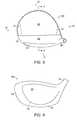
- FIG. 1is a toe side view of a golf club head according to an embodiment of the present invention
- FIG. 2is a heel side view of the golf club head according to the embodiment of FIG. 1 , except without the golf club shaft;
- FIG. 3is a top view of the golf club head according to the embodiment of FIG. 2 ;
- FIG. 4is a front view of a golf club head according to the embodiment FIG. 2 ;
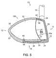
- FIG. 5is a cross-section view taken at V-V in FIG. 3 ;
- FIG. 6is a perspective view of a golf club head according to another embodiment of the present invention.
- FIG. 7is an exploded perspective view of the golf club head according to the embodiment of FIG. 6 ;
- FIG. 8is a toe side view of a golf club head according to another embodiment of the present invention.
- FIG. 9is a cross-section view of the golf club head according to the embodiment of FIG. 8 ;
- FIG. 10is a toe side view of a golf club head according to yet another embodiment of the present invention.
- FIG. 11is a cross-section view of the golf club head according to the embodiment of FIG. 10 ;
- FIG. 12is a perspective view of a golf club head in two parts according to yet another embodiment of the present invention, wherein (a) shows main body member 20 from a rear view perspective, and (b) shows secondary body member 30 removed from main body member 20 and rotated 180 degrees about a vertical axis;
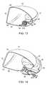
- FIG. 13is a cross-section perspective view of the golf club head according to the embodiment of FIG. 12 ;
- FIG. 14is a cross-section, exploded, perspective view of the golf club head according to the embodiment of FIG. 12 ;
- FIG. 15is a cross-section perspective view of a toe portion of the golf club head according to the embodiment of FIG. 12 ;
- FIG. 16is a cross-section perspective view of a heel portion of the golf club head according to the embodiment of FIG. 12 ;
- FIG. 17is a top view of a two golf club heads according to another embodiment of the present invention, wherein (a) shows the rear body member 30 a attached to front body member 20 and (b) shows a different rear body member 30 b attached to the same front body member;
- FIG. 18is a toe side view of a golf club head according to a further embodiment of the present invention.
- FIG. 19is a perspective view of the bottom portion of the golf club head according to the embodiment of FIG. 18 ;
- FIG. 20is a perspective view of the bottom portion of the golf club head, with the secondary body member removed, according to the embodiment of FIG. 18 ;
- FIG. 21is a cross-section side view of a rear portion of the gold club head according to the embodiment of FIG. 18 .
- directional terms used hereinsuch as “front,” “rear,” “side,” “top,” “bottom,” etc., refer to directions relative to the golf club head itself.
- frontrefers to that portion of the head 100 that would lay adjacent the golf ball when the club is positioned for swinging
- “rear” or “aft”refers to that portion of the golf club head that is substantially opposite to the front.
- Bottomor “sole” refers to the portion of head 100 that lays adjacent the ground when the golf club is positioned for swinging
- topor “crown” refers to that portion of the golf club head 100 that is opposite to the bottom.
- Hosel sideor “heel side” refers to the side of head 100 that is generally nearest the attachment of head 100 to a golf club shaft.
- Toe siderefers to the side of head 100 that is opposite to the hosel side.
- detachably attachedrefers to an attachment that is designed to be relatively easily undone and to prevent damaging or potentially damaging the attached parts during the detaching process.
- releasably joinedmay be used interchangeably with “detachably attached.” A detachable attachment requires only nominal forces to detach the parts from one another.
- a threaded fastenerwhich is designed to be readily unscrewed, is an example of a detachable attachment.
- An elastically deformable snap-lock fittingwhich can be unsnapped without being destroyed, so as to allow for two parts to come apart, is another example of a detachable attachment. This is true, even if a special tool is required to unsnap the fitting.
- An adhesive joint using an adhesive that can be softened or melted at a relatively low temperaturesuch as by applying heat via a conventional hair drier, propane torch, etc.), such that the two attached parts slip apart without being damaged, is another example of a detachable attachment.
- a detachable attachmentmay be temporary (if it is detached) or permanent (if it is never detached). Thus, if the threaded fastener in the above example is not unscrewed, the two joined parts will remain permanently detachably attached to one other.
- a brazed or welded jointwould not be considered to be detachable, as detaching the parts would require the application of either excessive, potentially damaging heat, forces or machining to detach the welded elements from one another.
- an adhesive jointthat is designed for permanent bonding and that requires the application of excessive, potentially damaging heat to burn the adhesive off or that requires the application of excessive, potentially damaging prying force to pull the joint apart, would not be considered to be detachable.
- a riveted jointthat generally requires alteration of the joined parts during the riveting process and that further requires unintended destruction of the rivet is not considered to be detachable.
- the design context and the context in which the attachment element is usedmust be taken into account.
- a threaded fastener with a locking feature that requires considerable force (i.e., potentially damaging the joined parts) to unlock and which was designed to provide a permanent, non-detachable attachmentwould not be considered to be detachable.
- a threaded fastener having a locking feature that requires only nominal force to overcome and which was selected and designed, for example, to reduce play in the jointmay be considered to be detachable.
- Such a threaded fastener with a locking featuremay be considered to be detachable even if the locking feature and/or the threaded fastener itself is destroyed during detachment.
- a first componentmay be attachably interchangeable with a second component in that both the first and the second components may be configured for alternative attachment to a third component.
- the first componentmay have a different mass, a different center-of-gravity and/or different moments-of-inertia than the second component, and thus, in the context of mass characteristics, the second component would not be interchangeable with the first component.
- the second componentmay be attachably interchangeable with the first component in that both the first and the second components may be alternatively attachable to the third component, even though the details of the attachment might vary.
- Interchangeable componentsare not necessarily detachably interchangeable.
- two componentsare attachably interchangeable if each could be attached to a third component in place of the other.
- the attachment of one of the componentsis formed with the third component, if the attachment is permanent, then even though the two components were attachably interchangeable, they are not detachably interchangeable. Only if the components are both detachably attachable and interchangeable are they detachably interchangeable.
- aspects of the present inventionrelate to systems for providing golf club heads, or other ball striking devices, that better control the mass properties of the individual golf club heads, thereby providing greater flexibility and customizability in the design of the overall golf club.
- a golf club headmay include: a front body member (or a main body member) detachably attached to a rear body member (or to a secondary body member).
- Front body member (or main body member)includes a striking surface and further may include a striking surface frame, a sole portion, a crown portion, a rear face substantially opposed to the striking surface and/or a hosel.
- the front body membermay include a crown or a portion thereof projecting rearwardly from a top portion of the striking surface frame, or a sole member or a portion thereof projecting rearwardly from a bottom portion of the striking surface frame, or both in at least some examples of the invention.
- the crown portionmay extend over at least 25% of an overall front-to-back dimension of the golf club head.
- the crown portionmay extend over at least 50% or even at least 80% of the overall front-to-back dimension of the golf club head.
- the rear or secondary body membermay be formed as a single piece from a single material, or as multiple pieces subsequently joined to one another.
- the rear body membermay be formed as a composite body, having multiple layers to build up the thickness.
- the rear body membermay be hollow in order to reduce its weight and to allow a club designer to better distribute the club head's mass within the overall club head structure, e.g., to increase its moment-of-inertia without increasing its mass, to control the center of gravity location, etc.
- the rear body membermay be designed as a substantially shell-like structure that defines a concavity.
- the rear body membermay be designed to receive or carry weight elements (not shown) for customizing the mass distribution of the rear body member and the golf club head. These weights may be attached after manufacture of the rear body member or may be included within the rear body member, for example, between the layers of a composite body member.
- two or more rear or secondary body membersmay be provided for interchangeable attachment to a front or main body member.
- Each of the interchangeably attachable rear body membersmay have a unique combination of center-of-gravity and moment-of-inertia characteristics.
- Each of the interchangeably attachable rear body membersmay also have a unique external shape, thus allowing a golfer to not only customize the performance characteristics of the golf club, but also to customize the look of the golf club head.
- the various rear body membersalso may be colored differently and/or finished differently, to enable customization and change of the aesthetic appearance of the golf club head.
- a means for detachably attaching the rear body members to the main body membere.g., a detachable attachment element
- a means for detachably attaching the interchangeable rear body members to the front body memberis provided for detachably attaching the interchangeable rear body members to the front body member.
- a golf club head systemhas a front or main body member, a first rear or secondary body member detachably attached to the front body member, and at least one other rear or secondary body member that is attachably interchangeable with the first rear body member.
- the first rear body memberis detachably attached.
- the other rear body member that is interchangeable with the first rear body membermay be detachably attachable or non-detachably attachable to the front body member.
- the rear body membermay be detachably attached to any part of the front body member, including, for example, to the striking surface, to a striking surface frame, to a crown portion, to a sole portion, to a rear surface, or to any combination thereof.
- a means for detachably attaching a rear body member to a front body membermay include an adhesive that melts or softens at relatively low temperatures.
- the adhesivemay be an epoxy adhesive having a debonding temperature less than 200° C., such that bonding and detaching parts becomes a matter of temperature change.
- One such known “removable” adhesivewas developed at the Sandia National Laboratory and is disclosed in U.S. Pat. No. 6,825,315.
- This removable adhesiveliquefies (i.e., melts) and loses its bonding capability at relatively low elevated temperatures (approximately from 90 degrees C. to 130 degrees C., depending upon the exact formulation) and then rebonds when the temperature is lowered (approximately from 20-25 degrees C., i.e., room temperature, to 60 degrees C.). Minimal force is required to debond (or separate) the bonded elements when this liquifying adhesive has liquefied.
- This patentis entirely incorporated herein by reference.
- a means for detachably attaching a rear or secondary body member to a front or main body membermay include one or more mechanical elements.
- the mechanical elementsmay include one or more threaded fasteners.
- the individual fastenerscould be longitudinally oriented in a front-to-rear direction, in a top-to-bottom direction, in a side-to-side direction or at an angle to any of these directions, depending upon the specific interface details, expected loads and/or accessibility concerns.
- threaded screwsmay fasten the rear body member to the front body member at the heel side and at the toe side of the club head.
- An additional threaded screwmay fasten the rear body member to the front body member at a crown or sole member portion of the front body member.
- one or more threaded screwsmay fasten the rear body member to the front body member at a rear surface of the front body member.
- these threaded screwsmay be “captured” by the rear body member, such that they are easily accessible when the rear body member is being attached to the front body member.
- the rear body membermay include threaded inserts, bosses or captured nuts for receiving the threaded fasteners.
- other mechanical fasteners and configurations of mechanical fastenersmay be utilized.
- the rear or secondary body membermay be detachably attached to the front or main body member using mechanical elements that may include one or more elastically-deformable elements.
- an elastically-deformable mechanical fastening elementmay include a biasing element.
- an elastically-deformable mechanical fastening elementmay include a snap-lock fastener. Such snap-lock fasteners could fasten the rear body member to the front body member at the heel side and at the toe side of the club head, at the top and at the bottom portions of the front body member, and/or at a rear surface of the front body member.
- an elastically-deformable mechanical fastening elementcould be used in conjunction with one or more threaded fasteners.
- Elastically-deformable fastening elementscould be made of any suitable material, such as metals and/or relatively hard plastics.
- a special toolif necessary, could be used to temporarily deform the fasteners such that the joined members may be easily detached.
- design featurescould be incorporated into the rear body member, the front body member or both to accommodate the use of a tool to assist in uncoupling the elastically-deformable elements.
- other elastically-deformable mechanical fastenersmay be used.
- the rear or secondary body membermay be detachably attached to the front or main body member using mechanical elements that may include one or more plastically-deformable and/or single-use elements.
- a plastically-deformable mechanical fastening elementmay include a nylon plug inserted into a hole in the threaded portion of a fastener. Such a plastically-deformable element assists in retaining the threaded fastener in the threaded bore and reducing vibration. However, if the amount of plastic deformation of the plug is minimal, the threaded fastener will still be detachable with only nominal forces from the threaded bore.
- a two-part shear pinmay mechanically fasten the rear body member to the front body member.
- the shear pinmay include an outer, plastically-deformable sleeve and an inner, non-deformable pin.
- This pincould join a lug-and-clevis arrangement of the rear body/front body members. Specifically, the lug and the clevis of the rear body/front body members could be aligned; the outer, plastically-deformable sleeve could be inserted into to the bores of the aligned lug-and-clevis; and then the inner, non-deformable pin could be inserted into the sleeve.
- the insertion of the inner pincould cause the outer sleeve to deform, thereby providing a slip and vibration free joint.
- the inner pinwould be pulled (or pushed) from the bores, thereby allowing the deformed outer sleeve to be removed from the bores.
- other plastically-deformable mechanical fastenersmay be used.
- a means for detachably attaching a rear or secondary body member to a front or main body membermay include both mechanical elements and adhesive elements.
- club head componentsmay be provided in a club head structure without departing from the invention.
- at least some golf club heads in accordance with examples of this inventionmay include weight members.
- the weight memberscould be movable and/or capable of being relocated to a variety of locations on the golf club head, thereby providing multiple weighting arrangements with respect to the club head structure.
- the various parts of the golf club headmay be made from any suitable or desired materials without departing from this invention, including steel (including stainless steel), titanium alloys, magnesium alloys, aluminum alloys, carbon fiber composite materials, glass fiber composite materials, carbon pre-preg materials, polymeric materials, and the like. Further, the various parts may be produced in any suitable or desired manner without departing from the invention, including casting, forging, molding (e.g., injection or blow molding), pressing, stamping, etc. Examples of polymeric materials that may be included in various parts of a club head structure include: thermoplastics (e.g., those suitable for use in injection or blow molding processes, such as thermoplastic polyurethanes, etc.), nylons, polyesters, and the like.
- the polymeric materialsmay also include metals or metal alloy components, e.g., to affect strength and/or to control weight or density.
- metals or metal alloy componentse.g., to affect strength and/or to control weight or density.
- the various parts of the front body membermay be held together as an integral structure in any suitable or desired manner, including by way of non-limiting examples, using mechanical connectors, adhesives, cements, welding, and the like.
- the various parts of the body membermay be held together as an integral structure in any suitable or desired manner, including by way of non-limiting examples, using mechanical connectors, adhesives, cements, welding, and the like.
- the various parts of the front body member and/or the rear body member, if anymay optionally be constructed from different materials, without departing from this invention.
- Such clubsmay include, for example, a club head of the type described above and a shaft extending from the head.
- the shaftmay be attached to the head in any suitable or desired manner, including in conventional manners known and used in the art, such as via adhesives, cements, welding, soldering, mechanical connectors (such as threads, retaining elements, or the like), releasable connections, etc.
- the shaftcould be detachably attached to the golf club head via a liquefying adhesive, as would be apparent to a person of ordinary skill in the art given the benefit of this disclosure.
- the shaftmay be made from any suitable or desired materials, including conventional materials known and used in the art, such as graphite based materials, other composite materials, steel materials (including stainless steel), aluminum materials, other metal alloy materials, and the like.
- a grip element or other handle membermay be attached to and/or extend from the shaft.
- Any desired grip materialsmay be used without departing from this invention, including rubber materials, leather materials, materials including cord or other fabric material embedded therein, polymeric materials, and the like.
- the grip elementmay be attached to the shaft in any suitable or desired manner, including in conventional manners known and used in the art, e.g., using adhesives or cements.
- the handle membermay be connected to the shaft, directly or indirectly, in any suitable or desired manner, such as via welding, soldering, adhesives, mechanical connectors (such as threads, retaining elements, etc.), or the like.
- various dimensions and/or characteristicsmay be achieved (such as various loft angles, face angles, head weights, lie angles, center of gravity angles, inset distances, lengths, breadths, heights, face thicknesses, crown thicknesses, sole thicknesses, body member wall thicknesses, hosel diameters, volumes, bulge radii, roll radii, body densities, etc.), e.g., depending on whether the golf club head is a driver, a 2-wood, a 3-wood, a 4-wood, a 5-wood, a 7-wood, a 9-wood, a wood-type hybrid club, etc.
- various dimensions and/or characteristicsmay be provided to suit a user's preferences and/or swing characteristics; to provide the desired launch angle, carry distance, and/or other characteristics for the club; etc.
- various different shaft characteristicssuch as stiffness, flex point, kick point, etc. may be used to further allow change and control over the club's and the club head's feel and characteristics.
- club heads in accordance with examples of this inventionmay use the club head design and/or geometry to produce other desired club head characteristics.
- the front body member of the club headwill be designed such that the club head will have a larger head and/or face length (e.g., heel to toe) relative to the club head's depth or breadth (e.g., front to back) and a “squared” structure, which results in a club head that is more torsionally stable (i.e., more resistant to twisting), thereby producing a more consistent, reliable, and/or straight golf ball flight.
- Golf club heads and golf clubs in accordance with at least some of these example aspects of the inventionmay include a front or main body member and/or a rear or secondary body member sized so as to provide a club head body having an overall club head length dimension L of at least 4.5 inches, at least 4.6 inches, at least 4.7 inches, at least 4.8 inches, or even at least 4.9 inches, and a ratio of an overall club head breadth dimension to the overall club head length dimension of 0.9 or more and 1 or less.
- Club heads in accordance with at least some examples of this inventionmay have a ratio of club head breadth to club head length of at least 0.94, at least 0.95, at least 0.96, at least 0.97, or even at least 0.98.
- the front or main body member and/or the rear or secondary body membermay be sized such that the overall club head breadth B dimension may be at least 4.2 inches, at least 4.3 inches, at least 4.4 inches, at least 4.5 inches, at least 4.6 inches, at least 4.7 inches, at least 4.8 inches, or even at least 4.9 inches.
- the club head body according to at least some examples of this aspect of the inventionmay be dimensioned such that the overall club head length dimension L is at least 4.7 inches, at least 4.8 inches, or even at least 4.9 inches, and/or such that the overall club head body size is 500 cm 3 or less, 470 cm 3 or less, or even 460 cm 3 or less.
- the interchangeable rear or secondary body memberwill be sized and shaped such that the overall club head body size or volume will be at least 350 cc, at least 400 cc, at least 420 cc, or even at least 450 cc.
- At least some example embodiments of golf club heads according to this inventionrelate to “wood-type” golf club heads, e.g., useful for drivers, fairway woods, utility or hybrid type clubs, or the like.
- Such club head structurestypically include a multiple piece construction and structure.
- FIGS. 1-5are views illustrating certain features of an embodiment of a golf club head 100 .
- Head 100includes a main body member 20 connected to a secondary body member 30 .
- head 100is connected to a golf club shaft 10 (see FIG. 1 ), thereby forming a complete golf club.
- Head 100includes a front 11 , a rear 12 a top 13 , a bottom 14 , a heel side 15 , and a toe side 16 .
- main body member 20(or front body member) is generally cup-shaped (i.e., formed as a substantially relatively thin-walled shell and defining an inner concavity) and includes striking surface 22 (also referred to as a face plate), a striking surface frame 24 , and a sole portion 26 .
- main body member 20is further illustrated with an external hosel 28 for attaching golf club shaft 10 to head 100 .
- Striking surface 22provides a contact area for engaging and propelling a golf ball in an intended direction.
- Striking surface 22need not have a flat strike surface.
- the strike surfacemay include horizontal grooves (not shown).
- Striking surface 22also may be curved, e.g., to include “bulge” and “roll” characteristics, as are commonly included in golf club head structures.
- Striking surface frame 24is connected to striking surface 22 .
- Frame 24may be integrally formed with or subsequently joined to striking surface 22 (e.g., by welding).
- frame 24extends around the perimeter of striking surface 22 and further extends in a depth direction toward the rear portion 12 of head 100 .
- frame 24may be formed of titanium metal or alloy (as is known and used in the art), may have a thickness ranging from approximately 0.01 inches to approximately 0.25 inches, and a depth ranging from approximately 0.1 inches to 2 inches (exclusive of any crown or sole portion that may be present). The thickness and depth contours of frame 24 need not be constant. Further, frame 24 may extend only partially around the perimeter of striking surface 22 . Even further, frame 24 need not be continuous.
- Sole portion 26is located on the bottom portion 14 of head 100 . Sole portion 26 projects from a lower edge of frame 24 , thereby extending toward the rear portion 12 of head 100 . Sole portion 26 may be integrally formed with or subsequently joined to frame 24 .
- sole portion 26may be formed of titanium metal or alloy, steel, or other material, may have a thickness ranging from approximately 0.01 inches to approximately 0.25 inches, and a side-to-side width ranging from approximately 1 inch to 5 inches. The thickness and width contours of sole plate 26 need not be constant. Sole portion 26 may extend all the way to the rear edge of head 100 . In one embodiment, sole portion 26 extends more than halfway across the front-to-rear length of head 100 .
- Secondary body member 30(or rear body member) is detachably attached to main body member 20 .
- secondary body member 30is formed as a hollow body.
- secondary body member 30includes an internal concavity 32 at least partially enclosed by walls 34 .
- Secondary body member 30further includes an opening that faces main body member 20 and is opposite to rear portion 12 of secondary body member 30 .
- secondary body member 30includes a perimeter flange 36 for complementary insertion into a perimeter flange 45 of main body member 20 .
- the perimeter flange 36 of secondary body member 30may overlay the perimeter member 45 of main body member 20 .
- a polymeric materiale.g., rubber, polytetrafluoroethylene, or other material
- a gasketmay be provided at the joint between secondary body member 30 and main body member 20 (e.g., fully or partially around the perimeter of the joint) to damped noise or vibration or reduce rattling.
- main body member 20 of the embodiment of FIGS. 1-5includes sole portion 26 .
- An elastically-deformable elementcouples secondary body member 30 to sole portion 26 in this example structure.
- the rearward-most end of sole portion 26includes a tab 49 .
- Tab 49is designed to slide into a slot 46 defined in secondary body member 30 , thereby coupling sole portion 26 to the bottom of secondary body member 30 .
- Tab 49is elastically deformable, thereby facilitating the insertion of tab 49 into slot 46 , and further providing a biasing of secondary body member 30 relative to main body member 20 . Biasing may be used to remove unwanted play between the two detachably attached members.
- a person of ordinary skill in the artwill appreciate that other fastening mechanisms may be used to detachably attach sole portion 26 to secondary body member 30 , given the benefit of this disclosure.
- sole plate 26includes a throughhole at its rearward-most end, so that sole portion 26 may be fastened to secondary body member 30 with a threaded fastener (e.g., threaded into a boss or an attached nut member included with the body member structure).
- a threaded fastenere.g., threaded into a boss or an attached nut member included with the body member structure.
- main body member 20includes a crown portion 21 .
- Crown portion 21projects rearwardly from a top portion of striking surface frame 24 .
- crown portion 21is integrally formed with frame 24 .
- a threaded fastener 40 cis provided to detachably attach secondary body member 30 to main body member 20 . Additional fasteners may be provided at other locations, if desired.
- Secondary body member 30may include a concavity 32 partially enclosed by walls 34 .
- the upper portion of a rear wall of secondary body member 30extends toward striking surface 22 and provides a platform for receiving the threaded portion of fastener 40 c .
- a flange 36overlaps a complementary flange 45 formed in the bottom portion of frame 24 .
- a layer of removable, liquefiable adhesive 50is located between the two flanges 45 and 30 . Further, a layer of removable, liquefiable adhesive 50 extends up and around the side walls and crown portion of main body member 20 where it interfaces with secondary body member 30 .
- fastener 40 cis removed and then the removable adhesive is heated until it melts. Upon liquefaction of the adhesive, secondary body member 30 is debonded from main body member 20 such that secondary body member 30 easily slides apart from main body member 20 .
- a through holeis provided to accept a portion of pin 42 a .
- a corresponding through hole for accepting a different portion of pin 42 ais provided in a top, rear portion of secondary body member 30 .
- a through holeis provided to accept a portion of pin 42 b .
- a corresponding through hole for accepting a different portion of pin 42 bis provided in a bottom, rear portion of secondary body member 30 .
- Pins 42 a , 42 bdetachably attach the rear portion of secondary body member 30 to the rear portions of main body member 20 (i.e., the rear portion of crown portion 21 and the rear portion of sole portion 26 ).
- pins 42 a and 42 bare elastically-deformable roll or spring pins.
- pins 42 a and 42 bmay include a plastically-deformable sleeve and a central (essentially) non-deformable pin.
- pins 42 a , 42 bare driven into cavity 31 with a pin driver. Then, projections 47 are disengaged from apertures 23 by either using a tool to push projections 47 inward or by squeezing the side walls of secondary body member 30 toward one another.
- the various club head components illustrated in FIGS. 10 and 11may be connected using other types of connectors, such as the threaded mechanical connectors described above.
- any number of fastening elementscan be provided on the golf club head and that the location and orientation of the fastening elements described herein are merely illustrative.
- Other suitable methods for detachably attaching secondary body member 30 to main body member 20will be apparent to persons of ordinary skill in the art, given the benefit of this disclosure.
- main body member 20includes a striking surface 22 , a sole portion 26 , a crown portion 21 , and a rear face 25 substantially opposed to striking surface 22 .
- the main body memberdefines an at least substantially enclosed main body cavity 29 .
- a secondary body member 30is detachably attached to the rear face 25 of main body member 20 .
- secondary body member 30extends over the entire rear face 25 of main body member 20 .
- secondary body member 30extends from the heel side 15 of club head 100 to the toe side 16 of the club head, and further, extends from the crown portion 21 of main body member 20 to the sole portion 26 of main body member.
- secondary body member 30may extend over only a portion of rear face 25 .
- Fastener 43 ais generally located adjacent the toe side 16 of club head 100 (see FIG. 15 ); fastener 43 b is generally located in a central region of the rear side 12 of club head 100 (see FIGS. 13 and 14 ); and fastener 43 c is generally located adjacent the heel side 15 of club head 100 (see FIG. 16 ).
- Secondary body member 30may include through holes to accommodate fasteners 43 a - 43 c (see FIG. 12( b )).
- main body member 20need not be flat nor need it parallel the contour of striking surface 22 . Rather, rear face 25 may be shaped or contoured to accommodate the attachment of secondary body member 30 . Further, as best shown in FIGS. 13-16 , main body member 20 may include corresponding bosses for receiving the threaded portions of fasteners 43 a - 43 c.
- secondary body member 30is shaped as a substantially shell-like structure such that an internal concavity 32 is defined therein.
- an enclosed or a substantially enclosed secondary body cavity 38is formed therebetween.
- rear face 25may be contoured to complement a matching surface of secondary body member 30 . If rear face 25 is contoured to complement a matching surface of secondary body member 30 , then no secondary body cavity would be formed therebetween.
- secondary body member 30may include a crown portion 37 and a sole portion 39 .
- the exterior surface of crown portion 37 of the secondary body memberlies substantially flush with the exterior surface of crown portion 21 of the main body member.
- the exterior surface of sole portion 39 of the secondary body memberlies substantially flush with the exterior surface of sole portion 26 of the main body member.
- an adhesivefor example, a liquefying epoxy, may be applied to some or all of the complementary surfaces of secondary body member 30 and main body member 20 .
- This adhesivemay be applied in lieu of the mechanical fastening elements or in addition to the mechanical fastening elements.
- one or more rear or secondary body members 30may be configured for interchangeable attachment to a front or main body member 20 .
- a first rear body member 30 amay be detachably attached to the front body member 20 (see FIG. 17( a )).
- At least one other rear body member 30 b that is attachably interchangeable with the first rear body member 30 amay be provided.
- the other rear body member 30 bmay be attached to front body member 20 in its stead (see FIG. 17( b )).
- either rear body member 30 a or rear body member 30 bmay be interchangeably attached to front body member 20 .
- Rear body member 30 ahas different characteristics from rear body member 30 b .
- rear body member 30 ahas a difference external shape, a different center-of-gravity, and different moment-of-inertia characteristics, when compared to rear body member 30 b .
- FIG. 17( a )rear body member 30 a has a rounded rear surface
- FIG. 17( b )rear body member 30 b has a more squared-off rear surface.
- rear body members 30 a and 30 bmay be formed of different materials or may have different finishes or looks.
- Other rear body members (not shown) with different characteristicsmay be provided for interchangeable attachment with front body member 20 .
- the systemmay further include the means for detachably attaching rear body members 30 a , 30 b to front body member 20 .
- such meanscould include mechanical fastening elements (such as, by way of non-limiting examples, threaded fasteners, elastically deformable elements, plastically deformable elements, tabs, pins, etc.) and/or adhesives (such as, by way of non-limiting example, a liquefying epoxy).
- main body member 20includes a striking surface 22 , a sole portion 26 , a crown portion 21 , and a rear face 25 (see FIGS. 20 nsd 21 ) substantially opposed to striking surface 22 .
- a secondary body member 30is detachably attached to the rear face 25 of main body member 20 .
- secondary body member 30extends over the entire rear face 25 of main body member 20 and over a portion of the sole of golf club head 100 .
- portions of the exterior sole portion 39 of secondary body member 30extend on either side of sole portion 26 of main body member 20 .
- Fasteners 43 d , 43 e and 43 fmechanically fasten secondary body member 30 to main body member 20 .
- Fasteners 43 d - 43 fgenerally extend perpendicular to sole portion 26 , i.e., vertically when the club is in the striking position. Although three fasteners are shown, fewer or more fasteners may be used to attach secondary body member 30 to main body member 20 .
- rear face 25may be shaped or contoured to accommodate the attachment of secondary body member 30 , for example, rear face 25 may include bosses for accommodating fasteners 43 d - 43 f .
- secondary body member 30is also shaped as a substantially shell-like structure such that an internal concavity 32 is defined therein. Thus, when secondary body member 30 is attached to main body member 20 , an enclosed or a substantially enclosed secondary body cavity 38 is formed therebetween.
- Transformable or convertible club heads of the types described hereinmay be used in conjunction with hosel members having releasable connections to golf club shafts and/or in conjunction with hosel members that allow adjustment of various club head characteristics (e.g., adjustment of lie angle, loft angle, or face angle, e.g., by adjusting the relative positioning of the shaft with respect to the hosel).
- Any desired releasable and/or adjustable club head/shaft connection structuresmay be used without departing from this invention, including such connection structures as are known, commercially available, and/or used in the art.
- club heads of the types described hereinmay be used in conjunction with the releasable and/or adjustable club head/shaft connection features described in U.S. Pat. No.
- the systemmay be used to provide an additional degree of individual golf club tailoring beyond what would otherwise be obtainable with known systems. For example, a golfer could easily test out multiple golf club head configurations in the shop prior to purchasing a customized club. Further, a golfer could also opt to purchase or take home more than one detachably interchangeable rear or secondary body member, thus having the readily available option of transforming or tailoring his or her golf club for different players, for different courses, for different weather conditions, for practicing different swing styles, etc.
- Retailerscould market these easily transformable golf club heads, when sold with more than one detachably interchangeable body member, as two-for-one specials, as a cost effective way to own multiple customized club configurations, as a cost effective way to keep up with the latest golf technology by merely updating the interchangeable members, etc.
- specific body memberscould be produced that match (or are associated with) the characteristics or specifications of the clubs used by professional golfers or other celebrities. Retailers could thus afford consumers an opportunity to test out a club having characteristics similar to the club used by the consumer's favorite celebrity golfer. Further, retailers could promote the sales of the customizable club heads by including the interchangeable body member associated with the celebrity golfer for free (or at a reduced price), when one or more other interchangeable body members are purchased by the consumer.
- the previously described featuresimprove the ability to customize and subsequently modify the mass characteristics of a golf club for any individual golfer.
- Golf clubs having customized mass characteristicsare meant to improve a golfer's swing control and swing compensation. While the various features of golf club head 100 work together to achieve the advantages previously described, it is recognized that individual features and sub-combinations of these features can be used to obtain some of the aforementioned advantages without the necessity to adopt all of these features.
Landscapes
- Health & Medical Sciences (AREA)
- General Health & Medical Sciences (AREA)
- Physical Education & Sports Medicine (AREA)
- Life Sciences & Earth Sciences (AREA)
- Engineering & Computer Science (AREA)
- Wood Science & Technology (AREA)
- Golf Clubs (AREA)
Abstract
Description
Claims (21)
Priority Applications (7)
| Application Number | Priority Date | Filing Date | Title |
|---|---|---|---|
| US12/192,402US8133128B2 (en) | 2008-08-15 | 2008-08-15 | Golf club head and system |
| EP09791403.0AEP2313167B1 (en) | 2008-08-15 | 2009-08-12 | Golf club head and golf club |
| PCT/US2009/053503WO2010019636A2 (en) | 2008-08-15 | 2009-08-12 | Golf club head and system |
| CN200980131863.XACN102123769B (en) | 2008-08-15 | 2009-08-12 | Golf club head and system |
| JP2011523129AJP5795533B2 (en) | 2008-08-15 | 2009-08-12 | Golf club head and system |
| CN201510737917.4ACN105344078B (en) | 2008-08-15 | 2009-08-12 | Golf club head and system |
| US13/365,342US8876623B2 (en) | 2008-08-15 | 2012-02-03 | Golf club head and system |
Applications Claiming Priority (1)
| Application Number | Priority Date | Filing Date | Title |
|---|---|---|---|
| US12/192,402US8133128B2 (en) | 2008-08-15 | 2008-08-15 | Golf club head and system |
Related Child Applications (1)
| Application Number | Title | Priority Date | Filing Date |
|---|---|---|---|
| US13/365,342ContinuationUS8876623B2 (en) | 2008-08-15 | 2012-02-03 | Golf club head and system |
Publications (2)
| Publication Number | Publication Date |
|---|---|
| US20100041494A1 US20100041494A1 (en) | 2010-02-18 |
| US8133128B2true US8133128B2 (en) | 2012-03-13 |
Family
ID=41565907
Family Applications (2)
| Application Number | Title | Priority Date | Filing Date |
|---|---|---|---|
| US12/192,402ActiveUS8133128B2 (en) | 2008-08-15 | 2008-08-15 | Golf club head and system |
| US13/365,342ActiveUS8876623B2 (en) | 2008-08-15 | 2012-02-03 | Golf club head and system |
Family Applications After (1)
| Application Number | Title | Priority Date | Filing Date |
|---|---|---|---|
| US13/365,342ActiveUS8876623B2 (en) | 2008-08-15 | 2012-02-03 | Golf club head and system |
Country Status (5)
| Country | Link |
|---|---|
| US (2) | US8133128B2 (en) |
| EP (1) | EP2313167B1 (en) |
| JP (1) | JP5795533B2 (en) |
| CN (2) | CN105344078B (en) |
| WO (1) | WO2010019636A2 (en) |
Cited By (29)
| Publication number | Priority date | Publication date | Assignee | Title |
|---|---|---|---|---|
| US20130178306A1 (en)* | 2005-04-21 | 2013-07-11 | Cobra Golf Incorporated | Golf club head with separable component |
| US20140187346A1 (en)* | 2005-04-21 | 2014-07-03 | Cobra Golf Incorporated | Golf club head with removable component |
| US8876623B2 (en) | 2008-08-15 | 2014-11-04 | Nike, Inc. | Golf club head and system |
| US9126085B2 (en) | 2013-03-15 | 2015-09-08 | Nike, Inc. | Golf club head structures having split, multi-part heads |
| US9421438B2 (en) | 2005-04-21 | 2016-08-23 | Cobra Golf Incorporated | Golf club head with accessible interior |
| US9440123B2 (en) | 2005-04-21 | 2016-09-13 | Cobra Golf Incorporated | Golf club head with accessible interior |
| US20180008871A1 (en)* | 2015-05-12 | 2018-01-11 | Karsten Manufacturing Corporation | Golf club head with selectively detachable face |
| US9873028B2 (en) | 2011-11-30 | 2018-01-23 | Nike, Inc. | Golf clubs and golf club heads |
| US9901792B2 (en) | 2011-11-30 | 2018-02-27 | Nike, Inc. | Golf clubs and golf club heads |
| US9901788B2 (en) | 2011-11-30 | 2018-02-27 | Nike, Inc. | Golf club head or other ball striking device |
| US9956463B2 (en) | 2011-11-30 | 2018-05-01 | Nike, Inc. | Golf clubs and golf club heads |
| US20180140907A1 (en)* | 2016-11-22 | 2018-05-24 | Karsten Manufacturing Corporation | Golf club head nicluding impact influencing flexure joint |
| US10022595B2 (en) | 2016-02-11 | 2018-07-17 | Sumitomo Rubber Industries, Ltd. | Golf club head customization |
| US10046211B2 (en)* | 2014-05-29 | 2018-08-14 | Nike, Inc. | Golf clubs and golf club heads |
| US10130849B2 (en) | 2015-05-29 | 2018-11-20 | Karsten Manufacturing Corporation | Golf clubs and golf club heads |
| US10661128B2 (en) | 2015-10-06 | 2020-05-26 | Sumitomo Rubber Industries, Ltd. | Adjustable club head |
| US10780329B2 (en) | 2015-10-06 | 2020-09-22 | Sumitomo Rubber Industries, Ltd. | Multi-component golf club wedge |
| US10881915B2 (en) | 2013-08-05 | 2021-01-05 | Karsten Manufacturing Corporation | Polymeric golf club head with metallic face |
| US10974102B2 (en) | 2010-12-28 | 2021-04-13 | Taylor Made Golf Company, Inc. | Golf club head |
| US11013965B2 (en)* | 2018-07-23 | 2021-05-25 | Taylor Made Golf Company, Inc. | Golf club heads |
| US11148021B2 (en) | 2010-12-28 | 2021-10-19 | Taylor Made Golf Company, Inc. | Golf club head |
| US11167184B2 (en)* | 2008-12-18 | 2021-11-09 | Karsten Manufacturing Corporation | Golf clubs and golf club heads having interchangeable rear body members |
| US11406881B2 (en) | 2020-12-28 | 2022-08-09 | Taylor Made Golf Company, Inc. | Golf club heads |
| US11446554B2 (en)* | 2007-10-12 | 2022-09-20 | Taylor Made Golf Company, Inc. | Golf club head with vertical center of gravity adjustment |
| US11497970B2 (en)* | 2018-12-13 | 2022-11-15 | Acushnet Company | Golf club head with improved inertia performance and removable aft body coupled by snap fit connection |
| US11554297B2 (en)* | 2016-01-05 | 2023-01-17 | Mod Golf Technologies, Llc | Adjustable interchangeable component golf club head |
| US11759685B2 (en) | 2020-12-28 | 2023-09-19 | Taylor Made Golf Company, Inc. | Golf club heads |
| US12296235B2 (en)* | 2023-04-28 | 2025-05-13 | Acushnet Company | Modular golf club including an interchangeable sole |
| US12390698B2 (en) | 2013-08-05 | 2025-08-19 | Karsten Manufacturing Corporation | Polymeric golf club head with metallic face |
Families Citing this family (20)
| Publication number | Priority date | Publication date | Assignee | Title |
|---|---|---|---|---|
| US9616301B2 (en) | 2005-04-21 | 2017-04-11 | Cobra Golf Incorporated | Releasable threaded component for a golf club having a mechanism for preventing over rotation |
| US8062151B2 (en) | 2008-08-15 | 2011-11-22 | Nike, Inc. | Golf club head and system |
| US9149693B2 (en) | 2009-01-20 | 2015-10-06 | Nike, Inc. | Golf club and golf club head structures |
| US8016691B2 (en)* | 2009-04-09 | 2011-09-13 | Nike, Inc. | Golf club head or other ball striking device having stiffened face portion |
| US8435135B2 (en)* | 2010-05-28 | 2013-05-07 | Nike, Inc. | Golf club head or other ball striking device having removable or interchangeable body member |
| US20150182835A1 (en)* | 2011-11-25 | 2015-07-02 | Xosé Antón Miragaya González | Golf club for helping a player to learn golf |
| US9855477B2 (en) | 2011-11-30 | 2018-01-02 | Nike, Inc. | Golf clubs and golf club heads |
| US9943733B2 (en)* | 2011-11-30 | 2018-04-17 | Nike, Inc. | Golf clubs and golf club heads |
| US9308423B1 (en)* | 2012-06-08 | 2016-04-12 | Callaway Golf Company | Golf club head with center of gravity adjustability |
| US11130025B2 (en)* | 2014-10-24 | 2021-09-28 | Karsten Manufacturing Corporation | Golf club heads with energy storage features |
| TWI636812B (en)* | 2014-10-24 | 2018-10-01 | 卡斯登製造公司 | Golf club head with energy storage characteristics and manufacturing method thereof |
| JP6309476B2 (en)* | 2015-03-18 | 2018-04-11 | 美津濃株式会社 | Wood type golf club head and wood type golf club |
| US9868036B1 (en)* | 2015-08-14 | 2018-01-16 | Taylormade Golf Company, Inc. | Golf club head |
| US11618306B2 (en) | 2016-10-27 | 2023-04-04 | Nicholas J. Singer | Skeleton for truck bed and convertible top |
| US20230044977A1 (en)* | 2018-12-13 | 2023-02-09 | Acushnet Company | Golf club head with separable aft body |
| US11446555B2 (en)* | 2018-12-13 | 2022-09-20 | Acushnet Company | Golf club head with improved inertia performance and removable aft body coupled by metal-composite joint |
| US20240058657A1 (en)* | 2018-12-13 | 2024-02-22 | Acushnet Company | Golf club head aft body construction |
| GB2618456B (en)* | 2019-07-24 | 2024-04-03 | Karsten Mfg Corp | Multi-component golf club head |
| US11839797B2 (en)* | 2021-09-24 | 2023-12-12 | Acushnet Company | Multi-material golf club head |
| JP7280937B1 (en)* | 2021-12-10 | 2023-05-24 | ホンマホールディングスグループリミテッド | golf club head |
Citations (81)
| Publication number | Priority date | Publication date | Assignee | Title |
|---|---|---|---|---|
| US1213382A (en) | 1916-05-10 | 1917-01-23 | Horace L Kent | Golf-club. |
| US1319233A (en) | 1919-10-21 | George w | ||
| US1359220A (en) | 1919-05-22 | 1920-11-16 | Richard F Beamer | Wooden golf-club |
| US1473528A (en) | 1920-11-09 | 1923-11-06 | D Milton Tootle | Golf club |
| US1525352A (en) | 1924-02-27 | 1925-02-03 | Aitken James Abram Garfield | Golf-club |
| US1567248A (en) | 1925-04-07 | 1925-12-29 | Joseph A Dahlman | Golf club |
| US1638916A (en) | 1926-06-04 | 1927-08-16 | Cuthbert S Butchart | Golf club |
| US1780625A (en) | 1924-04-17 | 1930-11-04 | Crawford Mcgregor & Canby Co | Golf-club head |
| US4021047A (en)* | 1976-02-25 | 1977-05-03 | Mader Robert J | Golf driver club |
| USD262049S (en) | 1979-08-06 | 1981-11-24 | Simmons Samuel P | Golf club head |
| USD268357S (en) | 1980-11-13 | 1983-03-22 | Mader Robert J | Golf driver club head |
| US4438931A (en)* | 1982-09-16 | 1984-03-27 | Kabushiki Kaisha Endo Seisakusho | Golf club head |
| US4618149A (en) | 1984-06-07 | 1986-10-21 | Maxel John M | Golf club having interchangeable face plates |
| US4653756A (en)* | 1985-10-25 | 1987-03-31 | Daiwa Golf Co., Ltd. | Golf club iron |
| US4681322A (en) | 1985-09-18 | 1987-07-21 | Straza George T | Golf club head |
| US4749197A (en) | 1987-03-11 | 1988-06-07 | Orlowski David C | Golf club |
| US4811950A (en) | 1986-07-31 | 1989-03-14 | Maruman Golf Co., Ltd. | Golf club head |
| US4824110A (en) | 1986-02-28 | 1989-04-25 | Maruman Golf, Co., Ltd. | Golf club head |
| US5190291A (en) | 1992-03-20 | 1993-03-02 | Melvin John N | Golf club which provides sensory information during a swing |
| US5232224A (en)* | 1990-01-22 | 1993-08-03 | Zeider Robert L | Golf club head and method of manufacture |
| US5255918A (en) | 1989-06-12 | 1993-10-26 | Donald A. Anderson | Golf club head and method of forming same |
| US5421577A (en) | 1993-04-15 | 1995-06-06 | Kobayashi; Kenji | Metallic golf clubhead |
| US5429357A (en)* | 1992-05-01 | 1995-07-04 | Kabushiki Kaisha Endo Seisakusho | Golf clubhead and its method of manufacturing |
| US5505453A (en) | 1994-07-20 | 1996-04-09 | Mack; Thomas E. | Tunable golf club head and method of making |
| US5509660A (en)* | 1993-08-17 | 1996-04-23 | Elmer; John C. | Golf clubs |
| US5611742A (en) | 1995-08-04 | 1997-03-18 | Kabushiki Kaisha Endo Seisakusho | Wood-type golf club head |
| US5632695A (en) | 1995-03-01 | 1997-05-27 | Wilson Sporting Goods Co. | Golf clubhead |
| US5665014A (en)* | 1993-11-02 | 1997-09-09 | Sanford; Robert A. | Metal golf club head and method of manufacture |
| US5743813A (en) | 1997-02-19 | 1998-04-28 | Chien Ting Precision Casting Co., Ltd. | Golf club head |
| US5776011A (en) | 1996-09-27 | 1998-07-07 | Echelon Golf | Golf club head |
| JPH11178955A (en) | 1997-12-18 | 1999-07-06 | Kurein Golf:Kk | Wood club head |
| US5935020A (en) | 1998-09-16 | 1999-08-10 | Tom Stites & Associates, Inc. | Golf club head |
| US5989134A (en) | 1998-05-21 | 1999-11-23 | Antonious; Anthony J. | Metalwood type club head with reinforced outer support system |
| US6004224A (en) | 1996-11-24 | 1999-12-21 | Hidetaka Tanaka | Golf club shaft, grip and socket |
| US6159109A (en) | 1996-03-29 | 2000-12-12 | Langslet; Eric B. | Vibrationally damped golf club head |
| US6165081A (en) | 1999-02-24 | 2000-12-26 | Chou; Pei Chi | Golf club head for controlling launch velocity of a ball |
| US6217461B1 (en) | 1996-04-30 | 2001-04-17 | Taylor Made Golf Company, Inc. | Golf club head |
| US6238300B1 (en) | 1998-09-18 | 2001-05-29 | Lawrence Y. Igarashi | Wood-type golf club head fabricated of metal sheets |
| US6332848B1 (en) | 1999-01-28 | 2001-12-25 | Cobra Golf Incorporated | Metal wood golf club head |
| US6354962B1 (en) | 1999-11-01 | 2002-03-12 | Callaway Golf Company | Golf club head with a face composed of a forged material |
| US20020065144A1 (en) | 2000-10-04 | 2002-05-30 | Callaway Golf Company | Multiple material golf club head with a polymer insert face |
| US6527650B2 (en)* | 1997-10-23 | 2003-03-04 | Callaway Golf Company | Internal weighting for a composite golf club head |
| US20030153401A1 (en)* | 1999-11-01 | 2003-08-14 | Callaway Golf Company | Golf Club Head with Customizable Center of Gravity |
| US6623378B2 (en)* | 2001-06-11 | 2003-09-23 | Taylor Made Golf Company, Inc. | Method for manufacturing and golf club head |
| US6663506B2 (en) | 2000-10-19 | 2003-12-16 | The Yokohama Rubber Co. | Golf club |
| US20030232659A1 (en) | 2002-06-17 | 2003-12-18 | Spalding Sports Worldwide, Inc. | Golf club head with peripheral weighting |
| US6695715B1 (en) | 1999-11-18 | 2004-02-24 | Bridgestone Sports Co., Ltd. | Wood club head |
| US20040097299A1 (en) | 2002-11-18 | 2004-05-20 | Callaway Golf Company | Golf club head |
| US6758763B2 (en) | 1999-11-01 | 2004-07-06 | Callaway Golf Company | Multiple material golf club head |
| US20040132541A1 (en) | 2002-12-19 | 2004-07-08 | Steve Macllraith | Individually customized golf club and process |
| US20040229714A1 (en)* | 2003-05-12 | 2004-11-18 | Bret Wahl | Iron-type golf club head and method for manufacturing it |
| US6825315B2 (en) | 2001-12-21 | 2004-11-30 | Sandia Corporation | Method of making thermally removable adhesives |
| US20040248667A1 (en) | 2003-05-27 | 2004-12-09 | Callaway Golf Company | [GOLF CLUB HEAD (Corporate Docket PU2150)] |
| US20050026714A1 (en) | 1999-11-01 | 2005-02-03 | Stevens Daniel M. | Golf club head with customizable center of gravity |
| US20050043112A1 (en) | 1999-11-01 | 2005-02-24 | Stevens Daniel M. | Golf club head with customizable center of gravity |
| US20050049072A1 (en) | 2002-07-24 | 2005-03-03 | Burrows Bruce D. | Temporary golf club shaft-component connection |
| US6884179B2 (en) | 2001-06-13 | 2005-04-26 | Taylor Made Golf Company, Inc. | Golf club and method for making it |
| JP2005287679A (en) | 2004-03-31 | 2005-10-20 | Daiwa Seiko Inc | Golf club head |
| US20050239576A1 (en) | 2005-05-10 | 2005-10-27 | Nike, Inc. | Golf clubs and golf club heads |
| US20060040765A1 (en) | 2004-08-19 | 2006-02-23 | Sri Sports Ltd. | Golf putter head |
| US20060052174A1 (en) | 2004-04-19 | 2006-03-09 | Callaway Golf Company | Golf club head with gasket |
| GB2418623A (en) | 2004-10-04 | 2006-04-05 | Bridgestone Sports Co Ltd | Hollow golf club head |
| US20060100028A1 (en) | 2004-11-05 | 2006-05-11 | Min-Hui Kuo | Golf club head |
| US20060128500A1 (en) | 2004-12-14 | 2006-06-15 | Nike, Inc. | Golf club head or other ball striking device with discrete regions of different density |
| US7166041B2 (en) | 2005-01-28 | 2007-01-23 | Callaway Golf Company | Golf clubhead with adjustable weighting |
| EP1752198A1 (en) | 2005-08-10 | 2007-02-14 | Thielen Feinmechanik GmbH & Co. Fertigungs KG | Golf club with centered weight attachment |
| US7281985B2 (en)* | 2004-08-24 | 2007-10-16 | Callaway Golf Company | Golf club head |
| US7306527B2 (en) | 2005-01-03 | 2007-12-11 | Callaway Golf Company | Golf club head |
| WO2008050074A1 (en) | 2006-10-25 | 2008-05-02 | Brian Alzano Mayes | Golf club |
| CN201067612Y (en) | 2007-03-09 | 2008-06-04 | 复盛股份有限公司 | Golf wooden club head structure |
| US7410428B1 (en) | 2007-03-09 | 2008-08-12 | Callaway Golf Company | Golf club head with high moment of inertia |
| US7413517B2 (en) | 2005-01-25 | 2008-08-19 | Butler Jr Joseph H | Reconfigurable golf club and method |
| US20090088272A1 (en) | 2005-01-03 | 2009-04-02 | Callaway Golf Company | Golf club head |
| US20090143167A1 (en)* | 2007-11-09 | 2009-06-04 | Callaway Golf Company | Golf club head with adjustable weighting, customizable face-angle, and variable bulge and roll face |
| US7566276B2 (en)* | 2006-04-14 | 2009-07-28 | Dogleg Right Corporation | Multi-piece putter head having an insert |
| US20090203465A1 (en) | 2008-02-11 | 2009-08-13 | Nike, Inc. | Golf Clubs and Golf Club Heads Having Targeted Weighting Characteristics |
| WO2009102693A1 (en) | 2008-02-14 | 2009-08-20 | Nike, Inc. | Extreme weighted hybrid and other wood-type golf clubs and golf club heads |
| US20090270199A1 (en) | 2008-04-24 | 2009-10-29 | Yung-Hsiung Chen | Golf club head |
| US20100041495A1 (en) | 2008-08-12 | 2010-02-18 | Dick's Sporting Goods, Inc. | Golf driver head with exchangeable rear sections |
| US7878924B2 (en) | 2006-11-27 | 2011-02-01 | Cobra Golf Inc. | Quick release connection system for golf clubs |
| US20110294589A1 (en)* | 2010-05-28 | 2011-12-01 | Nike, Inc. | GOLF CLUB HEAD OR OTHER BALL STRIKING DEVICE HAVING REMOVABLE or INTERCHANGEABLE BODY MEMBER |
Family Cites Families (34)
| Publication number | Priority date | Publication date | Assignee | Title |
|---|---|---|---|---|
| US645944A (en) | 1899-11-29 | 1900-03-27 | Spalding & Bros Ag | Golf-club. |
| US1000982A (en) | 1910-06-01 | 1911-08-22 | Alexander W Biddle | Golf-club. |
| US1322182A (en) | 1918-12-13 | 1919-11-18 | Alexander Duncan | Golf-club. |
| JPH0639058A (en)* | 1992-04-10 | 1994-02-15 | Maruman Golf Corp | Coupling method for golf club head and shaft |
| JPH07236716A (en)* | 1993-11-02 | 1995-09-12 | Design Metal Inc | Metal golf club head and its production |
| US6440009B1 (en)* | 1994-05-30 | 2002-08-27 | Taylor Made Golf Co., Inc. | Golf club head and method of assembling a golf club head |
| US5518243A (en)* | 1995-01-25 | 1996-05-21 | Zubi Golf Company | Wood-type golf club head with improved adjustable weight configuration |
| JPH09215786A (en)* | 1996-02-15 | 1997-08-19 | Mitsubishi Materials Corp | Golf club head and production thereof |
| US6386990B1 (en)* | 1997-10-23 | 2002-05-14 | Callaway Golf Company | Composite golf club head with integral weight strip |
| US6162133A (en)* | 1997-11-03 | 2000-12-19 | Peterson; Lane | Golf club head |
| JP4154506B2 (en) | 1998-10-29 | 2008-09-24 | ブリヂストンスポーツ株式会社 | Wood club head |
| JP2000176056A (en) | 1998-12-15 | 2000-06-27 | Endo Mfg Co Ltd | Golf wood club |
| JP3932233B2 (en)* | 1998-12-31 | 2007-06-20 | 信幸 御船 | Golf club head |
| US6575845B2 (en)* | 1999-11-01 | 2003-06-10 | Callaway Golf Company | Multiple material golf club head |
| US6381828B1 (en) | 1999-11-01 | 2002-05-07 | Callaway Golf Company | Chemical etching of a striking plate for a golf club head |
| US20030134690A1 (en) | 2002-01-17 | 2003-07-17 | Chen Archer C.C. | Golf club head of compound material |
| JP2004337327A (en)* | 2003-05-15 | 2004-12-02 | Mitsuhiro Saso | Metal wood club |
| JP2003310804A (en) | 2003-06-05 | 2003-11-05 | Mizuno Corp | Metal wood club head |
| US7082665B2 (en) | 2004-06-22 | 2006-08-01 | Callaway Golf Company | Method for processing a golf club head with cup shaped face component |
| JP2006130065A (en)* | 2004-11-05 | 2006-05-25 | Bridgestone Sports Co Ltd | Golf club head |
| JP2008526311A (en)* | 2005-01-03 | 2008-07-24 | キャラウェイ・ゴルフ・カンパニ | Golf club head |
| CN2877785Y (en)* | 2005-09-05 | 2007-03-14 | 复盛股份有限公司 | golf club head construction |
| JP4760320B2 (en) | 2005-11-15 | 2011-08-31 | 横浜ゴム株式会社 | Golf club head and golf club |
| WO2007076304A2 (en)* | 2005-12-29 | 2007-07-05 | Callaway Golf Company | Golf club head with customizable center of gravity |
| US20080070721A1 (en)* | 2006-09-20 | 2008-03-20 | Fu Sheng Industrial Co., Ltd. | Weight-adjustable golf club head provided with rear lightweight covering |
| US8096897B2 (en) | 2006-12-19 | 2012-01-17 | Taylor Made Golf Company, Inc. | Golf club-heads having a particular relationship of face area to face mass |
| US7601078B2 (en) | 2007-03-29 | 2009-10-13 | Karsten Manufacturing Corporation | Golf club head with non-metallic body |
| US7722475B2 (en) | 2007-07-06 | 2010-05-25 | Nike, Inc. | Releasable and interchangeable connections for golf club heads and shafts |
| US7704156B2 (en) | 2007-07-06 | 2010-04-27 | Nike, Inc. | Releasable and interchangeable connections for golf club heads and shafts |
| US7722474B2 (en) | 2007-07-06 | 2010-05-25 | Nike, Inc. | Releasable and interchangeable connections for golf club heads and shafts |
| US20090062029A1 (en) | 2007-08-28 | 2009-03-05 | Nike, Inc. | Releasable and Interchangeable Connections for Golf Club Heads and Shafts |
| US7883430B2 (en) | 2008-07-22 | 2011-02-08 | Nike, Inc. | Releasable and interchangeable connections for golf club heads and shafts |
| US8133128B2 (en) | 2008-08-15 | 2012-03-13 | Nike, Inc. | Golf club head and system |
| US8062151B2 (en) | 2008-08-15 | 2011-11-22 | Nike, Inc. | Golf club head and system |
- 2008
- 2008-08-15USUS12/192,402patent/US8133128B2/enactiveActive
- 2009
- 2009-08-12CNCN201510737917.4Apatent/CN105344078B/ennot_activeExpired - Fee Related
- 2009-08-12CNCN200980131863.XApatent/CN102123769B/ennot_activeExpired - Fee Related
- 2009-08-12WOPCT/US2009/053503patent/WO2010019636A2/enactiveApplication Filing
- 2009-08-12JPJP2011523129Apatent/JP5795533B2/enactiveActive
- 2009-08-12EPEP09791403.0Apatent/EP2313167B1/enactiveActive
- 2012
- 2012-02-03USUS13/365,342patent/US8876623B2/enactiveActive
Patent Citations (92)
| Publication number | Priority date | Publication date | Assignee | Title |
|---|---|---|---|---|
| US1319233A (en) | 1919-10-21 | George w | ||
| US1213382A (en) | 1916-05-10 | 1917-01-23 | Horace L Kent | Golf-club. |
| US1359220A (en) | 1919-05-22 | 1920-11-16 | Richard F Beamer | Wooden golf-club |
| US1473528A (en) | 1920-11-09 | 1923-11-06 | D Milton Tootle | Golf club |
| US1525352A (en) | 1924-02-27 | 1925-02-03 | Aitken James Abram Garfield | Golf-club |
| US1780625A (en) | 1924-04-17 | 1930-11-04 | Crawford Mcgregor & Canby Co | Golf-club head |
| US1567248A (en) | 1925-04-07 | 1925-12-29 | Joseph A Dahlman | Golf club |
| US1638916A (en) | 1926-06-04 | 1927-08-16 | Cuthbert S Butchart | Golf club |
| US4021047A (en)* | 1976-02-25 | 1977-05-03 | Mader Robert J | Golf driver club |
| USD262049S (en) | 1979-08-06 | 1981-11-24 | Simmons Samuel P | Golf club head |
| USD268357S (en) | 1980-11-13 | 1983-03-22 | Mader Robert J | Golf driver club head |
| US4438931A (en)* | 1982-09-16 | 1984-03-27 | Kabushiki Kaisha Endo Seisakusho | Golf club head |
| US4618149A (en) | 1984-06-07 | 1986-10-21 | Maxel John M | Golf club having interchangeable face plates |
| US4681322A (en) | 1985-09-18 | 1987-07-21 | Straza George T | Golf club head |
| US4653756A (en)* | 1985-10-25 | 1987-03-31 | Daiwa Golf Co., Ltd. | Golf club iron |
| US4824110A (en) | 1986-02-28 | 1989-04-25 | Maruman Golf, Co., Ltd. | Golf club head |
| US4811950A (en) | 1986-07-31 | 1989-03-14 | Maruman Golf Co., Ltd. | Golf club head |
| US4749197A (en) | 1987-03-11 | 1988-06-07 | Orlowski David C | Golf club |
| US5255918A (en) | 1989-06-12 | 1993-10-26 | Donald A. Anderson | Golf club head and method of forming same |
| US5232224A (en)* | 1990-01-22 | 1993-08-03 | Zeider Robert L | Golf club head and method of manufacture |
| US5190291A (en) | 1992-03-20 | 1993-03-02 | Melvin John N | Golf club which provides sensory information during a swing |
| US5429357A (en)* | 1992-05-01 | 1995-07-04 | Kabushiki Kaisha Endo Seisakusho | Golf clubhead and its method of manufacturing |
| US5421577A (en) | 1993-04-15 | 1995-06-06 | Kobayashi; Kenji | Metallic golf clubhead |
| US5509660A (en)* | 1993-08-17 | 1996-04-23 | Elmer; John C. | Golf clubs |
| US5665014A (en)* | 1993-11-02 | 1997-09-09 | Sanford; Robert A. | Metal golf club head and method of manufacture |
| US5505453A (en) | 1994-07-20 | 1996-04-09 | Mack; Thomas E. | Tunable golf club head and method of making |
| US5632695A (en) | 1995-03-01 | 1997-05-27 | Wilson Sporting Goods Co. | Golf clubhead |
| US5611742A (en) | 1995-08-04 | 1997-03-18 | Kabushiki Kaisha Endo Seisakusho | Wood-type golf club head |
| US6159109A (en) | 1996-03-29 | 2000-12-12 | Langslet; Eric B. | Vibrationally damped golf club head |
| US6217461B1 (en) | 1996-04-30 | 2001-04-17 | Taylor Made Golf Company, Inc. | Golf club head |
| US5776011A (en) | 1996-09-27 | 1998-07-07 | Echelon Golf | Golf club head |
| US6004224A (en) | 1996-11-24 | 1999-12-21 | Hidetaka Tanaka | Golf club shaft, grip and socket |
| US5743813A (en) | 1997-02-19 | 1998-04-28 | Chien Ting Precision Casting Co., Ltd. | Golf club head |
| US6527650B2 (en)* | 1997-10-23 | 2003-03-04 | Callaway Golf Company | Internal weighting for a composite golf club head |
| JPH11178955A (en) | 1997-12-18 | 1999-07-06 | Kurein Golf:Kk | Wood club head |
| US5989134A (en) | 1998-05-21 | 1999-11-23 | Antonious; Anthony J. | Metalwood type club head with reinforced outer support system |
| US5935020A (en) | 1998-09-16 | 1999-08-10 | Tom Stites & Associates, Inc. | Golf club head |
| US6238300B1 (en) | 1998-09-18 | 2001-05-29 | Lawrence Y. Igarashi | Wood-type golf club head fabricated of metal sheets |
| US6332848B1 (en) | 1999-01-28 | 2001-12-25 | Cobra Golf Incorporated | Metal wood golf club head |
| US6165081A (en) | 1999-02-24 | 2000-12-26 | Chou; Pei Chi | Golf club head for controlling launch velocity of a ball |
| US20030153401A1 (en)* | 1999-11-01 | 2003-08-14 | Callaway Golf Company | Golf Club Head with Customizable Center of Gravity |
| US6354962B1 (en) | 1999-11-01 | 2002-03-12 | Callaway Golf Company | Golf club head with a face composed of a forged material |
| US20050026714A1 (en) | 1999-11-01 | 2005-02-03 | Stevens Daniel M. | Golf club head with customizable center of gravity |
| US6926619B2 (en) | 1999-11-01 | 2005-08-09 | Callaway Golf Company | Golf club head with customizable center of gravity |
| US6739983B2 (en) | 1999-11-01 | 2004-05-25 | Callaway Golf Company | Golf club head with customizable center of gravity |
| US6758763B2 (en) | 1999-11-01 | 2004-07-06 | Callaway Golf Company | Multiple material golf club head |
| US20050043112A1 (en) | 1999-11-01 | 2005-02-24 | Stevens Daniel M. | Golf club head with customizable center of gravity |
| US6695715B1 (en) | 1999-11-18 | 2004-02-24 | Bridgestone Sports Co., Ltd. | Wood club head |
| US20020065144A1 (en) | 2000-10-04 | 2002-05-30 | Callaway Golf Company | Multiple material golf club head with a polymer insert face |
| US6663506B2 (en) | 2000-10-19 | 2003-12-16 | The Yokohama Rubber Co. | Golf club |
| US6623378B2 (en)* | 2001-06-11 | 2003-09-23 | Taylor Made Golf Company, Inc. | Method for manufacturing and golf club head |
| US6884179B2 (en) | 2001-06-13 | 2005-04-26 | Taylor Made Golf Company, Inc. | Golf club and method for making it |
| US6825315B2 (en) | 2001-12-21 | 2004-11-30 | Sandia Corporation | Method of making thermally removable adhesives |
| US20030232659A1 (en) | 2002-06-17 | 2003-12-18 | Spalding Sports Worldwide, Inc. | Golf club head with peripheral weighting |
| US6988960B2 (en) | 2002-06-17 | 2006-01-24 | Callaway Golf Company | Golf club head with peripheral weighting |
| US20050049072A1 (en) | 2002-07-24 | 2005-03-03 | Burrows Bruce D. | Temporary golf club shaft-component connection |
| US6890269B2 (en) | 2002-07-24 | 2005-05-10 | Burrows Golf, Llc | Temporary golf club shaft-component connection |
| US20040097299A1 (en) | 2002-11-18 | 2004-05-20 | Callaway Golf Company | Golf club head |
| US7108611B2 (en)* | 2002-12-19 | 2006-09-19 | Macilraith Steve | Individually customized golf club and process |
| US20040132541A1 (en) | 2002-12-19 | 2004-07-08 | Steve Macllraith | Individually customized golf club and process |
| US20040229714A1 (en)* | 2003-05-12 | 2004-11-18 | Bret Wahl | Iron-type golf club head and method for manufacturing it |
| US20040248667A1 (en) | 2003-05-27 | 2004-12-09 | Callaway Golf Company | [GOLF CLUB HEAD (Corporate Docket PU2150)] |
| JP2005287679A (en) | 2004-03-31 | 2005-10-20 | Daiwa Seiko Inc | Golf club head |
| US7285060B2 (en) | 2004-04-19 | 2007-10-23 | Callaway Golf Company | Golf club head with gasket |
| US20060052174A1 (en) | 2004-04-19 | 2006-03-09 | Callaway Golf Company | Golf club head with gasket |
| US20060040765A1 (en) | 2004-08-19 | 2006-02-23 | Sri Sports Ltd. | Golf putter head |
| US7281985B2 (en)* | 2004-08-24 | 2007-10-16 | Callaway Golf Company | Golf club head |
| GB2418623A (en) | 2004-10-04 | 2006-04-05 | Bridgestone Sports Co Ltd | Hollow golf club head |
| US20060100028A1 (en) | 2004-11-05 | 2006-05-11 | Min-Hui Kuo | Golf club head |
| US20060128500A1 (en) | 2004-12-14 | 2006-06-15 | Nike, Inc. | Golf club head or other ball striking device with discrete regions of different density |
| US20090088272A1 (en) | 2005-01-03 | 2009-04-02 | Callaway Golf Company | Golf club head |
| US7306527B2 (en) | 2005-01-03 | 2007-12-11 | Callaway Golf Company | Golf club head |
| US7413517B2 (en) | 2005-01-25 | 2008-08-19 | Butler Jr Joseph H | Reconfigurable golf club and method |
| US7166041B2 (en) | 2005-01-28 | 2007-01-23 | Callaway Golf Company | Golf clubhead with adjustable weighting |
| US20050239576A1 (en) | 2005-05-10 | 2005-10-27 | Nike, Inc. | Golf clubs and golf club heads |
| EP1752198A1 (en) | 2005-08-10 | 2007-02-14 | Thielen Feinmechanik GmbH & Co. Fertigungs KG | Golf club with centered weight attachment |
| US7632193B2 (en) | 2005-08-10 | 2009-12-15 | Thielen Feinmechanik Gmbh & Co. Fertigungs Kg | Golf club |
| US20070037633A1 (en) | 2005-08-10 | 2007-02-15 | Thielen Feinmechanik Gmbh & Co. Fertigungs Kg | Golf club |
| US7566276B2 (en)* | 2006-04-14 | 2009-07-28 | Dogleg Right Corporation | Multi-piece putter head having an insert |
| US20090247319A1 (en) | 2006-04-14 | 2009-10-01 | Billings David P | Multi-piece putter head having an insert |
| WO2008050074A1 (en) | 2006-10-25 | 2008-05-02 | Brian Alzano Mayes | Golf club |
| US7878924B2 (en) | 2006-11-27 | 2011-02-01 | Cobra Golf Inc. | Quick release connection system for golf clubs |
| US7431667B2 (en) | 2007-03-09 | 2008-10-07 | Callaway Golf Company | Golf club head with high moment of inertia |
| US7410428B1 (en) | 2007-03-09 | 2008-08-12 | Callaway Golf Company | Golf club head with high moment of inertia |
| CN201067612Y (en) | 2007-03-09 | 2008-06-04 | 复盛股份有限公司 | Golf wooden club head structure |
| US20090143167A1 (en)* | 2007-11-09 | 2009-06-04 | Callaway Golf Company | Golf club head with adjustable weighting, customizable face-angle, and variable bulge and roll face |
| US20090203465A1 (en) | 2008-02-11 | 2009-08-13 | Nike, Inc. | Golf Clubs and Golf Club Heads Having Targeted Weighting Characteristics |
| WO2009102576A2 (en) | 2008-02-11 | 2009-08-20 | Nike, Inc. | Golf clubs and golf club heads having targeted weighting characteristics |
| WO2009102693A1 (en) | 2008-02-14 | 2009-08-20 | Nike, Inc. | Extreme weighted hybrid and other wood-type golf clubs and golf club heads |
| US20090270199A1 (en) | 2008-04-24 | 2009-10-29 | Yung-Hsiung Chen | Golf club head |
| US20100041495A1 (en) | 2008-08-12 | 2010-02-18 | Dick's Sporting Goods, Inc. | Golf driver head with exchangeable rear sections |
| US20110294589A1 (en)* | 2010-05-28 | 2011-12-01 | Nike, Inc. | GOLF CLUB HEAD OR OTHER BALL STRIKING DEVICE HAVING REMOVABLE or INTERCHANGEABLE BODY MEMBER |
Non-Patent Citations (17)
| Title |
|---|
| Final Office Action issued Apr. 19, 2011 in related application U.S. Appl. No. 12/725,547. |
| International Search Report and Written Opinion issued Feb. 26, 2010 in corresponding PCT Application No. PCT/US2009/053503. |
| International Search Report and Written Opinion issued Feb. 9, 2010 in corresponding PCT Application No. PCT/US2009/053502. |
| Notice of Allowance issued Jul. 14, 2011 in related application U.S. Appl. No. 12/192,429. |
| Office Action issued Jan. 26, 2011 in divisional application U.S. Appl. No. 12/725,547. |
| Office Action issued Jul. 28, 2011 in related application U.S. Appl. No. 12/725,547. |
| Office Action issued Jun. 21, 2010 in U.S. Appl. No. 12/192,429. |
| Office Action issued Mar. 3, 2011 in related U.S. Appl. No. 12/192,429. |
| Office Action issued Nov. 30, 2010 in related application U.S. Appl. No. 12/192,429. |
| Office Action issued Nov. 30, 2010 in related application U.S. Appl. No. 12/725,547. |
| Office Action issued Sep. 16, 2010 in child application U.S. Appl. No. 12/725,547. |
| Sandia-developed Removable Adhesive Bonds and Detaches with Temperature Changes, Sandia National Laboratories News Release, Sep. 25, 2001. Printed Mar. 26, 2008: http://www.sandia.gov/media/NewsRel/NR2001/adhesive.htm. |
| U.S. Appl. No. 11/774,513, filed Jul. 6, 2007 in the name of Tavares et al. |
| U.S. Appl. No. 11/774,519, filed Jul. 6, 2007 in the name of Thomas et al. |
| U.S. Appl. No. 11/774,522, filed Jul. 6, 2007 in the name of Stites et al. |
| U.S. Appl. No. 11/846,370, filed Aug. 28, 2007 in the name of Stites et al. |
| U.S. Appl. No. 12/177,778, filed Jul. 22, 2008 in the name of Thomas et al. |
Cited By (65)
| Publication number | Priority date | Publication date | Assignee | Title |
|---|---|---|---|---|
| US9901794B2 (en) | 2005-04-21 | 2018-02-27 | Cobra Golf Incorporated | Golf club head with removable component |
| US9855474B2 (en) | 2005-04-21 | 2018-01-02 | Cobra Golf Incorporated | Golf club head with accessible interior |
| US20130178306A1 (en)* | 2005-04-21 | 2013-07-11 | Cobra Golf Incorporated | Golf club head with separable component |
| US20140187346A1 (en)* | 2005-04-21 | 2014-07-03 | Cobra Golf Incorporated | Golf club head with removable component |
| US9393471B2 (en)* | 2005-04-21 | 2016-07-19 | Cobra Golf Incorporated | Golf club head with removable component |
| US9421438B2 (en) | 2005-04-21 | 2016-08-23 | Cobra Golf Incorporated | Golf club head with accessible interior |
| US9440123B2 (en) | 2005-04-21 | 2016-09-13 | Cobra Golf Incorporated | Golf club head with accessible interior |
| US9504889B2 (en) | 2005-04-21 | 2016-11-29 | Cobra Golf Incorporated | Golf club with multi-component construction |
| US11446554B2 (en)* | 2007-10-12 | 2022-09-20 | Taylor Made Golf Company, Inc. | Golf club head with vertical center of gravity adjustment |
| US20230049276A1 (en)* | 2007-10-12 | 2023-02-16 | Taylor Made Golf Company, Inc. | Golf club head with vertical center of gravity adjustment |
| US11857852B2 (en)* | 2007-10-12 | 2024-01-02 | Taylor Made Golf Company, Inc. | Golf club head with vertical center of gravity adjustment |
| US8876623B2 (en) | 2008-08-15 | 2014-11-04 | Nike, Inc. | Golf club head and system |
| US11167184B2 (en)* | 2008-12-18 | 2021-11-09 | Karsten Manufacturing Corporation | Golf clubs and golf club heads having interchangeable rear body members |
| US20220062720A1 (en)* | 2008-12-18 | 2022-03-03 | Karsten Manufacturing Corporation | Golf Clubs and Golf Club Heads Having Interchangeable Rear Body Members |
| US20240082657A1 (en)* | 2008-12-18 | 2024-03-14 | Karsten Manufacturing Corporation | Golf Clubs and Golf Club Heads Having Interchangeable Rear Body Members |
| US11865415B2 (en)* | 2008-12-18 | 2024-01-09 | Karsten Manufacturing Corporation | Golf clubs and golf club heads having interchangeable rear body members |
| US20240082658A1 (en)* | 2008-12-18 | 2024-03-14 | Karsten Manufacturing Corporation | Golf Clubs and Golf Club Heads Having Interchangeable Rear Body Members |
| US11654336B2 (en) | 2010-12-28 | 2023-05-23 | Taylor Made Golf Company, Inc. | Golf club head |
| US10974102B2 (en) | 2010-12-28 | 2021-04-13 | Taylor Made Golf Company, Inc. | Golf club head |
| US11148021B2 (en) | 2010-12-28 | 2021-10-19 | Taylor Made Golf Company, Inc. | Golf club head |
| US9956463B2 (en) | 2011-11-30 | 2018-05-01 | Nike, Inc. | Golf clubs and golf club heads |
| US9950218B2 (en) | 2011-11-30 | 2018-04-24 | Nike, Inc. | Golf club head or other ball striking device |
| US9901788B2 (en) | 2011-11-30 | 2018-02-27 | Nike, Inc. | Golf club head or other ball striking device |
| US9901792B2 (en) | 2011-11-30 | 2018-02-27 | Nike, Inc. | Golf clubs and golf club heads |
| US9873028B2 (en) | 2011-11-30 | 2018-01-23 | Nike, Inc. | Golf clubs and golf club heads |
| US12070662B2 (en) | 2013-03-15 | 2024-08-27 | Karsten Manufacturing Corporation | Golf club head structures having split, multi-part heads |
| US10500448B2 (en) | 2013-03-15 | 2019-12-10 | Karsten Manufacturing Corporation | Golf club head structures having split, multi-part heads |
| US9849352B2 (en) | 2013-03-15 | 2017-12-26 | Karsten Manufacturing Corporation | Golf club head structures having split, multi-part heads |
| US9126085B2 (en) | 2013-03-15 | 2015-09-08 | Nike, Inc. | Golf club head structures having split, multi-part heads |
| US11040255B2 (en) | 2013-03-15 | 2021-06-22 | Karsten Manufacturing Corporation | Golf club head structures having split, multi-part heads |
| US11623123B2 (en) | 2013-08-05 | 2023-04-11 | Karsten Manufacturing Corporation | Polymeric golf club head with metallic face |
| US10881915B2 (en) | 2013-08-05 | 2021-01-05 | Karsten Manufacturing Corporation | Polymeric golf club head with metallic face |
| US12390698B2 (en) | 2013-08-05 | 2025-08-19 | Karsten Manufacturing Corporation | Polymeric golf club head with metallic face |
| US10046211B2 (en)* | 2014-05-29 | 2018-08-14 | Nike, Inc. | Golf clubs and golf club heads |
| US20180008871A1 (en)* | 2015-05-12 | 2018-01-11 | Karsten Manufacturing Corporation | Golf club head with selectively detachable face |
| US10729947B2 (en) | 2015-05-29 | 2020-08-04 | Karsten Manufacturing Corporation | Golf clubs and golf club heads |
| US10130849B2 (en) | 2015-05-29 | 2018-11-20 | Karsten Manufacturing Corporation | Golf clubs and golf club heads |
| US11285364B2 (en) | 2015-05-29 | 2022-03-29 | Karsten Manufacturing Corporation | Golf clubs and golf club heads |
| US20220219052A1 (en)* | 2015-05-29 | 2022-07-14 | Karsten Manufacturing Corporation | Golf Clubs and Golf Club Heads |
| US10449426B2 (en) | 2015-05-29 | 2019-10-22 | Karsten Manufacturing Corporation | Golf clubs and golf club heads with removable dampening member in sole |
| US10780329B2 (en) | 2015-10-06 | 2020-09-22 | Sumitomo Rubber Industries, Ltd. | Multi-component golf club wedge |
| US10661128B2 (en) | 2015-10-06 | 2020-05-26 | Sumitomo Rubber Industries, Ltd. | Adjustable club head |
| US11554297B2 (en)* | 2016-01-05 | 2023-01-17 | Mod Golf Technologies, Llc | Adjustable interchangeable component golf club head |
| US12161917B2 (en) | 2016-01-05 | 2024-12-10 | Mod Golf Technologies, Llc | Adjustable interchangeable component golf club head |
| US10463924B2 (en) | 2016-02-11 | 2019-11-05 | Sumitomo Rubber Industries, Ltd. | Golf club head customization |
| US11020635B2 (en) | 2016-02-11 | 2021-06-01 | Sumitomo Rubber Industries, Ltd. | Golf club head customization |
| US11524212B2 (en) | 2016-02-11 | 2022-12-13 | Sumitomo Rubber Industries, Ltd. | Golf club head customization |
| US12064668B2 (en) | 2016-02-11 | 2024-08-20 | Sumitomo Rubber Industries, Ltd. | Golf club head customization |
| US10022595B2 (en) | 2016-02-11 | 2018-07-17 | Sumitomo Rubber Industries, Ltd. | Golf club head customization |
| US11167186B2 (en) | 2016-11-22 | 2021-11-09 | Karsten Manufacturing Corporation | Golf club head including impact influencing flexure joint |
| US20180140907A1 (en)* | 2016-11-22 | 2018-05-24 | Karsten Manufacturing Corporation | Golf club head nicluding impact influencing flexure joint |
| US12296236B2 (en) | 2016-11-22 | 2025-05-13 | Karsten Manufacturing Corporation | Golf club head including impact influencing flexture joint |
| JP2022172143A (en)* | 2016-11-22 | 2022-11-15 | カーステン マニュファクチュアリング コーポレーション | Golf club head including impact-influencing flexure joint |
| US20190209901A1 (en)* | 2016-11-22 | 2019-07-11 | Karsten Manufacturing Corporation | Golf club head including impact influencing flexture joint |
| US10758790B2 (en)* | 2016-11-22 | 2020-09-01 | Karsten Manufacturing Corporation | Golf club head including impact influencing flexture joint |
| US10279225B2 (en)* | 2016-11-22 | 2019-05-07 | Karsten Manufacturing Corporation | Golf club head including impact influencing flexure joint |
| US11400350B2 (en) | 2018-07-23 | 2022-08-02 | Taylor Made Golf Company, Inc. | Golf club heads |
| US11771963B2 (en) | 2018-07-23 | 2023-10-03 | Taylor Made Golf Company, Inc. | Golf club heads |
| US11013965B2 (en)* | 2018-07-23 | 2021-05-25 | Taylor Made Golf Company, Inc. | Golf club heads |
| US11497970B2 (en)* | 2018-12-13 | 2022-11-15 | Acushnet Company | Golf club head with improved inertia performance and removable aft body coupled by snap fit connection |
| US11975248B2 (en) | 2020-12-28 | 2024-05-07 | Taylor Made Golf Company, Inc. | Golf club heads |
| US11406881B2 (en) | 2020-12-28 | 2022-08-09 | Taylor Made Golf Company, Inc. | Golf club heads |
| US11759685B2 (en) | 2020-12-28 | 2023-09-19 | Taylor Made Golf Company, Inc. | Golf club heads |
| US12390703B2 (en) | 2020-12-28 | 2025-08-19 | Taylor Made Golf Company, Inc. | Golf club heads |
| US12296235B2 (en)* | 2023-04-28 | 2025-05-13 | Acushnet Company | Modular golf club including an interchangeable sole |
Also Published As
| Publication number | Publication date |
|---|---|
| CN102123769B (en) | 2015-12-09 |
| CN105344078B (en) | 2018-02-02 |
| US20100041494A1 (en) | 2010-02-18 |
| WO2010019636A3 (en) | 2010-04-22 |
| US20120129621A1 (en) | 2012-05-24 |
| JP2012500045A (en) | 2012-01-05 |
| US8876623B2 (en) | 2014-11-04 |
| WO2010019636A2 (en) | 2010-02-18 |
| CN102123769A (en) | 2011-07-13 |
| CN105344078A (en) | 2016-02-24 |
| JP5795533B2 (en) | 2015-10-14 |
| EP2313167B1 (en) | 2019-01-09 |
| EP2313167A2 (en) | 2011-04-27 |
Similar Documents
| Publication | Publication Date | Title |
|---|---|---|
| US8133128B2 (en) | Golf club head and system | |
| US8062151B2 (en) | Golf club head and system | |
| JP5506698B2 (en) | Golf club and golf club head having adjustable weight members | |
| JP6082366B2 (en) | Golf club and golf club head having interchangeable rear body members | |
| US8033930B2 (en) | Weight element for a golf club | |
| EP2550070B1 (en) | Golf clubs and golf club heads with separate portions | |
| TWM261254U (en) | Golf club head | |
| US8986134B2 (en) | Golf club and golf club head with an insert-receiving feature |
Legal Events
| Date | Code | Title | Description |
|---|---|---|---|
| AS | Assignment | Owner name:NIKE USA, INC.,OREGON Free format text:ASSIGNMENT OF ASSIGNORS INTEREST;ASSIGNORS:BOYD, ROBERT;TAVARES, GARY G.;STITES, JOHN THOMAS;SIGNING DATES FROM 20080904 TO 20080908;REEL/FRAME:021576/0707 Owner name:NIKE, INC.,OREGON Free format text:ASSIGNMENT OF ASSIGNORS INTEREST;ASSIGNOR:NIKE USA, INC.;REEL/FRAME:021576/0720 Effective date:20080918 Owner name:NIKE, INC., OREGON Free format text:ASSIGNMENT OF ASSIGNORS INTEREST;ASSIGNOR:NIKE USA, INC.;REEL/FRAME:021576/0720 Effective date:20080918 Owner name:NIKE USA, INC., OREGON Free format text:ASSIGNMENT OF ASSIGNORS INTEREST;ASSIGNORS:BOYD, ROBERT;TAVARES, GARY G.;STITES, JOHN THOMAS;SIGNING DATES FROM 20080904 TO 20080908;REEL/FRAME:021576/0707 | |
| AS | Assignment | Owner name:NIKE, INC., OREGON Free format text:ASSIGNMENT OF ASSIGNORS INTEREST;ASSIGNOR:CHENG, CHIA-CHYI;REEL/FRAME:027099/0351 Effective date:20110929 | |
| STCF | Information on status: patent grant | Free format text:PATENTED CASE | |
| FPAY | Fee payment | Year of fee payment:4 | |
| AS | Assignment | Owner name:KARSTEN MANUFACTURING CORPORATION, ARIZONA Free format text:ASSIGNMENT OF ASSIGNORS INTEREST;ASSIGNOR:NIKE, INC.;REEL/FRAME:041823/0161 Effective date:20170127 | |
| MAFP | Maintenance fee payment | Free format text:PAYMENT OF MAINTENANCE FEE, 8TH YEAR, LARGE ENTITY (ORIGINAL EVENT CODE: M1552); ENTITY STATUS OF PATENT OWNER: LARGE ENTITY Year of fee payment:8 | |
| MAFP | Maintenance fee payment | Free format text:PAYMENT OF MAINTENANCE FEE, 12TH YEAR, LARGE ENTITY (ORIGINAL EVENT CODE: M1553); ENTITY STATUS OF PATENT OWNER: LARGE ENTITY Year of fee payment:12 |