US8132687B2 - Double-walled container and method of manufacture - Google Patents
Double-walled container and method of manufactureDownload PDFInfo
- Publication number
- US8132687B2 US8132687B2US12/492,963US49296309AUS8132687B2US 8132687 B2US8132687 B2US 8132687B2US 49296309 AUS49296309 AUS 49296309AUS 8132687 B2US8132687 B2US 8132687B2
- Authority
- US
- United States
- Prior art keywords
- container
- metal container
- diameter
- double
- metal
- Prior art date
- Legal status (The legal status is an assumption and is not a legal conclusion. Google has not performed a legal analysis and makes no representation as to the accuracy of the status listed.)
- Active, expires
Links
Images


Classifications
- B—PERFORMING OPERATIONS; TRANSPORTING
- B65—CONVEYING; PACKING; STORING; HANDLING THIN OR FILAMENTARY MATERIAL
- B65D—CONTAINERS FOR STORAGE OR TRANSPORT OF ARTICLES OR MATERIALS, e.g. BAGS, BARRELS, BOTTLES, BOXES, CANS, CARTONS, CRATES, DRUMS, JARS, TANKS, HOPPERS, FORWARDING CONTAINERS; ACCESSORIES, CLOSURES, OR FITTINGS THEREFOR; PACKAGING ELEMENTS; PACKAGES
- B65D81/00—Containers, packaging elements, or packages, for contents presenting particular transport or storage problems, or adapted to be used for non-packaging purposes after removal of contents
- B65D81/38—Containers, packaging elements, or packages, for contents presenting particular transport or storage problems, or adapted to be used for non-packaging purposes after removal of contents with thermal insulation
- B65D81/3865—Containers, packaging elements, or packages, for contents presenting particular transport or storage problems, or adapted to be used for non-packaging purposes after removal of contents with thermal insulation drinking cups or like containers
- B65D81/3869—Containers, packaging elements, or packages, for contents presenting particular transport or storage problems, or adapted to be used for non-packaging purposes after removal of contents with thermal insulation drinking cups or like containers formed with double walls, i.e. hollow
- B—PERFORMING OPERATIONS; TRANSPORTING
- B65—CONVEYING; PACKING; STORING; HANDLING THIN OR FILAMENTARY MATERIAL
- B65D—CONTAINERS FOR STORAGE OR TRANSPORT OF ARTICLES OR MATERIALS, e.g. BAGS, BARRELS, BOTTLES, BOXES, CANS, CARTONS, CRATES, DRUMS, JARS, TANKS, HOPPERS, FORWARDING CONTAINERS; ACCESSORIES, CLOSURES, OR FITTINGS THEREFOR; PACKAGING ELEMENTS; PACKAGES
- B65D81/00—Containers, packaging elements, or packages, for contents presenting particular transport or storage problems, or adapted to be used for non-packaging purposes after removal of contents
- B65D81/38—Containers, packaging elements, or packages, for contents presenting particular transport or storage problems, or adapted to be used for non-packaging purposes after removal of contents with thermal insulation
- B65D81/3837—Containers, packaging elements, or packages, for contents presenting particular transport or storage problems, or adapted to be used for non-packaging purposes after removal of contents with thermal insulation rigid container in the form of a bottle, jar or like container
- B65D81/3841—Containers, packaging elements, or packages, for contents presenting particular transport or storage problems, or adapted to be used for non-packaging purposes after removal of contents with thermal insulation rigid container in the form of a bottle, jar or like container formed with double walls, i.e. hollow
- B—PERFORMING OPERATIONS; TRANSPORTING
- B65—CONVEYING; PACKING; STORING; HANDLING THIN OR FILAMENTARY MATERIAL
- B65D—CONTAINERS FOR STORAGE OR TRANSPORT OF ARTICLES OR MATERIALS, e.g. BAGS, BARRELS, BOTTLES, BOXES, CANS, CARTONS, CRATES, DRUMS, JARS, TANKS, HOPPERS, FORWARDING CONTAINERS; ACCESSORIES, CLOSURES, OR FITTINGS THEREFOR; PACKAGING ELEMENTS; PACKAGES
- B65D83/00—Containers or packages with special means for dispensing contents
- B65D83/14—Containers for dispensing liquid or semi-liquid contents by internal gaseous pressure, i.e. aerosol containers comprising propellant
- B65D83/38—Details of the container body
- Y—GENERAL TAGGING OF NEW TECHNOLOGICAL DEVELOPMENTS; GENERAL TAGGING OF CROSS-SECTIONAL TECHNOLOGIES SPANNING OVER SEVERAL SECTIONS OF THE IPC; TECHNICAL SUBJECTS COVERED BY FORMER USPC CROSS-REFERENCE ART COLLECTIONS [XRACs] AND DIGESTS
- Y10—TECHNICAL SUBJECTS COVERED BY FORMER USPC
- Y10S—TECHNICAL SUBJECTS COVERED BY FORMER USPC CROSS-REFERENCE ART COLLECTIONS [XRACs] AND DIGESTS
- Y10S220/00—Receptacles
- Y10S220/906—Beverage can, i.e. beer, soda
- Y—GENERAL TAGGING OF NEW TECHNOLOGICAL DEVELOPMENTS; GENERAL TAGGING OF CROSS-SECTIONAL TECHNOLOGIES SPANNING OVER SEVERAL SECTIONS OF THE IPC; TECHNICAL SUBJECTS COVERED BY FORMER USPC CROSS-REFERENCE ART COLLECTIONS [XRACs] AND DIGESTS
- Y10—TECHNICAL SUBJECTS COVERED BY FORMER USPC
- Y10T—TECHNICAL SUBJECTS COVERED BY FORMER US CLASSIFICATION
- Y10T29/00—Metal working
- Y10T29/49—Method of mechanical manufacture
- Y10T29/49826—Assembling or joining
- Y10T29/49908—Joining by deforming
- Y10T29/49938—Radially expanding part in cavity, aperture, or hollow body
- Y10T29/4994—Radially expanding internal tube
- Y—GENERAL TAGGING OF NEW TECHNOLOGICAL DEVELOPMENTS; GENERAL TAGGING OF CROSS-SECTIONAL TECHNOLOGIES SPANNING OVER SEVERAL SECTIONS OF THE IPC; TECHNICAL SUBJECTS COVERED BY FORMER USPC CROSS-REFERENCE ART COLLECTIONS [XRACs] AND DIGESTS
- Y10—TECHNICAL SUBJECTS COVERED BY FORMER USPC
- Y10T—TECHNICAL SUBJECTS COVERED BY FORMER US CLASSIFICATION
- Y10T29/00—Metal working
- Y10T29/49—Method of mechanical manufacture
- Y10T29/49826—Assembling or joining
- Y10T29/49908—Joining by deforming
- Y10T29/49938—Radially expanding part in cavity, aperture, or hollow body
- Y10T29/49941—Peripheral edge joining of abutting plates
Definitions
- Metal containersare commonly comprised of metal.
- Metal containersmay take several forms such as a drinking cup, can, bottle, or aerosol.
- Metal containersmay be manufactured by several methods including: drawing, drawing and ironing, draw reverse draw, drawing and stretching, deep drawing, 3-piece seaming, and impact extrusion.
- Metal containersmay be finished in many different ways including curling, flanging, threading, seaming, etc.
- a method of manufacturing a double-walled containercomprises providing a first container having a diameter X; providing a second container having a diameter Y, wherein the diameter Y is larger than the diameter X; inserting the first container into the second container; and interlocking the first container and the second container.
- interlocking the first container and the second containercomprises expanding the diameter X of a portion of the first container and narrowing the diameter Y of a portion of the second container.
- the diameter Y of a portion of the second containerexpands as the diameter X of a portion of the first container is expanded.
- interlocking the first container and the second containercomprises expanding the diameter X of a portion of the first container and curling a top edge of the first container.
- a top edge of the second containeris curled as the top edge of the first container is curled.
- interlocking the first container and the second containercomprises expanding the diameter X of a portion of the first container and double-seaming a top edge of the first container.
- a top edge of the second containeris double-seamed as the top edge of the first container is double-seamed.
- interlocking the first container and the second containercomprises narrowing the diameters of a portion of the first container and a portion of the second container.
- a gaplies between a portion of the first container and a portion of the second container. In some embodiments, an opening of the double-walled container is narrowed to accept a closure. In some embodiments, the first container and/or the second container have ribs.
- a double-walled containercomprises an inner container; and an outer container wherein the inner container and the outer container are interlocked.
- a diameter of a top portion of the outer containerhas been narrowed.
- a diameter of a portion of the inner containerhas been narrowed.
- a diameter of a portion of the inner containerhas been expanded.
- a diameter of a portion of the outer containerhas been expanded.
- the first and/or second containershave ribs.
- a gaplies between a portion of the first container and a portion of the second container.
- a top edge of the first containeris curled.
- a top edge of the first containeris formed to accept a closure.
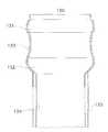
- FIG. 1shows a cross-section of a double-walled container according to one embodiment of the invention.
- FIG. 2shows a cross-section of a double-walled container according to another embodiment of the invention.
- FIG. 3shows a cross-section of a double-walled container according to yet another embodiment of the invention.
- FIG. 4shows a series of containers after undergoing process steps in a series of process steps according to an embodiment of the invention.
- FIG. 5shows a series of containers after undergoing process steps in a series of process steps according to another embodiment of the invention.
- FIG. 6Ashows a partial cross-section of a first container inside a second container.
- FIG. 6Bshows a partial cross-section of a double-walled container according to one embodiment of the invention.
- FIG. 6Cshows a partial cross-section of a double-walled container according to another embodiment of the invention.
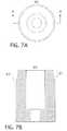
- FIG. 7Ashows a top view of an expansion die used to manufacture the double-walled container of FIG. 4B .
- FIG. 7Bshows a cross-section along line A-A view of the expansion die of FIG. 7A .
- FIG. 8Ashows a top view of an expansion die used to manufacture the double-walled container of FIG. 4D .
- FIG. 8Eshows a cross-section along line A-A of the expansion die of FIG. 5A .
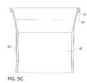
- FIG. 9Aillustrates a top view of a double-walled container according to yet another embodiment of the invention.
- FIG. 9Billustrates a cross-section along line A-A of the double-walled container of FIG. 9A .
- FIG. 9Cillustrates a partial cross-section along line A-A of the double-walled container of FIG. of 9 A.
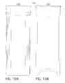
- FIG. 10Ashows a side view of a double-walled container according to a further embodiment of the invention.
- FIG. 10Bdepicts a cross-section along line A-A of the double-walled container of FIG. 10A .
- FIG. 10Cshows a partial cross-section along line A-A of the double-walled container of FIG. 10A .
- FIG. 10Dillustrates a partial side view of the double-walled container of FIG. 10A .
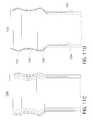
- FIG. 11Ashows a side view of a double-walled container according to yet a further embodiment of the invention.
- FIG. 11Bdepicts a cross-section along line A-A of the double-walled container of FIG. 11A .
- FIG. 11Cshows a partial side view of the double-walled container of FIG. 11A .
- FIG. 11Dillustrates a partial cross-section along line A-A of the double-walled container of FIG. 11A .
- FIG. 12Adepicts a double-walled container according to another embodiment of the invention.
- FIG. 12Bshows a partial close up view of the double-walled container of FIG. 12A .
- FIG. 13illustrates a partial cross-section view of a double-walled container according to yet a further embodiment of the invention.
- FIG. 14depicts two examples of double-walled containers according to embodiments of the invention wherein the outside wall of each of the double-walled containers is ribbed.
- FIG. 15depicts two examples of double-walled containers according to embodiments of the invention wherein the inside wall of each of the double-walled containers is ribbed.
- FIG. 16shows a partial cross-section view of yet a further embodiment of the invention.
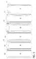
- FIG. 17is a graph showing the heat up rate of the side-wall of a double-walled container vs. the side-wall of a single-walled container.
- FIG. 18is a graph showing the heat tip rate of water in a double-walled container vs. water in a single-walled container.
- a method of manufacturing a double-walled containercomprises providing a first container having a diameter X; providing a second container having a diameter Y, wherein the diameter Y is larger than the diameter X; inserting the first container into the second container; and interlocking the first container and the second container so that the first and second containers form a single double-walled container.
- Interlocking the first container and the second containermeans securing the first container at least partially inside of the second container to prevent axial movement of the first container relative to the second container.
- interlocking the first container and the second containermay comprise expanding the diameter X of a portion of the first container and narrowing a portion of the second container along with an expanded portion of the first container.
- the portion of the second and/or first container that is narrowedis a smaller portion than the portion that had been expanded.
- interlocking the first container and the second containermay comprise expanding the diameter X of a portion of the first container and curling or seaming the top edges of both containers or of the first container. Any other appropriate methods of finishing the edges or forming the opening of the double-walled container to accept a closure may be used.
- interlocking the first container and the second containercomprises narrowing the diameter Y of a portion of the second container and curling or seaming the top edges of both containers or of the first container. In some embodiments, interlocking the first container and the second container comprises narrowing the diameter Y of a portion of the second container and narrowing the diameter X of a portion of the first container.
- FIGS. 1-3each show a double-walled container 10 , 20 , and 30 , respectively, wherein the top portions 13 , 23 , and 33 , respectively, of both the first container 11 , 21 , and 31 , respectively, and the second container 12 , 22 , and 32 respectively, have been expanded.
- the top edges of containers 11 , 12 , 21 , 22 , 31 and 32are curled.
- First container 11is interlocked with second container 12 .
- First container 21is interlocked with second container 22 .
- first container 31is interlocked with second container 32 .
- FIGS. 4 and 5show containers after certain example manufacturing steps according to some embodiments of the invention.
- the first container 40 in step Astarted with a 53 mm diameter.
- step Ba top portion 41 of the first container 40 had been expanded to a 57.4 mm diameter.
- the expansionwas accomplished by using a the expansion die shown in FIG. 7 .
- step Ca second container 42 , having a 59 mm diameter was provided.
- step Dthe first container 40 was placed inside the second container 42 . A small clearance between the two containers prevented air from being trapped and compressed.
- both containerswere expanded together using a larger diameter expansion die shown in FIG. 8 , by inserting the die into the partially expanded first container.
- the expansion die shown in FIG. 8The expansion die shown in FIG.
- step Eexpanded the top portion of the partially expanded can an additional 0.059′′ (1.5 mm) per side to a diameter of 60.4 mm.
- the die travelwas adjusted to produce the desired length of expanded surface.
- step Ea top portion 44 of both containers was narrowed, via die necking without a knockout, to a diameter of 59 mm.
- Step Fanother top portion of both containers was expanded.
- step Gtop edges of both containers were double seamed.
- step Aa first container 50 , having a 53 mm diameter, was provided.
- step Ba top portion 52 of the first container 50 was expanded.
- step Ca second container 51 having a 59 mm diameter was provided.
- step Dthe first container 50 was placed inside the second container 51 and top portions of the first container 50 and the second container 51 were expanded together.
- step Etop portions of the first container 50 and the second container 51 were narrowed, via die necking without a knockout, to a diameter of 59 mm.
- step Ftop edges of both containers 50 and 51 were curled outward.
- a lower or middle portion of the first and/or second containersmay be expanded and/or narrowed.
- a method of manufacturing a double-walled containercomprises providing a first container having a diameter X; providing a second container having a diameter Y, wherein the diameter Y is larger than the diameter X; inserting the first container into the second container; and narrowing a top portion of the second container.
- a knockoutis used in the narrowing process.
- the second containermay be necked, using a knockout, to a diameter just slightly larger than the first container, the first container is then placed inside the second container and then a knockout is placed inside the first container and both the first and second containers are necked together.
- FIG. 16shows double-walled container 164 wherein the first container 165 and the second container 166 have been interlocked by narrowing both the first container and the second container.
- FIGS. 6A-6Cshow the effects of steps in an interlocking process according to one embodiment of the invention.
- FIG. 6Ashows a first container 63 resting inside a second container 64 .
- a portion 65 of the first container 63has been expanded so that there is little clearance between the first container and the second container 64 .
- FIG. 6Ba second portion 66 of the first container 63 has been expanded along with a portion 67 of the second container 64 .
- a second portion 69 of the second container 64has been narrowed along w/a third portion 68 of the first container 63 .
- the first container 63has been interlocked to the second container 64 .
- the first and second containersstart out having the same diameters.
- the step of providing a second container having a diameter Ycomprises providing a second container having a diameter having a diameter Z and expanding the second container to the diameter Y.
- the diameter Zmay equal the diameter X, or Z may be a different diameter than X.
- the step of providing the first container having a diameter Xcomprises providing a first container having a diameter W and narrowing the first container to a diameter X.
- the diameter Wmay equal to the diameter Y or W may be a different diameter than Y.
- the sidewalls of the first and second containersare straight, i.e. have a substantially uniform diameter at the beginning of the process, as shown, for example, in FIGS. 4A , 4 C, 5 A and 5 C.
- the sidewalls of the first and second containersare curved or tapered.
- the double-walled container shown in FIG. 3could be manufactured with first and second containers having curved sidewalls.
- the dome 14 of the first container 11is not of a substantially similar size and/or shape of the dome 15 of the second container 12 so that the dome of the first container does not nest into the dome of the second container. This enhances the thermal insulating properties of the double-walled container 10 .
- the non-nesting dome configurationcan be observed in FIGS. 1-3 .
- a gap 16lies between a portion of the first container and a portion of the second container.
- the width of the gap 16is about 0.080′′ to about 0.085′′ in some areas.
- the width of the gap 16is about 0.020′′ to about 0.040′′ is some areas, about 0.060′′ to about 0.080′′ in some areas, or about 0.020′′ to about 0.125′′ in some areas.
- the width of the gapis 0.080′′, there is a 0.160′′ difference in diameter between the first (inner) container and the second (outer) container.
- the width of the gapis not uniform in some embodiments.
- this gap 16may be filled partially or completely with air or another insulating material. Any appropriate insulating material may be used.
- expanding the diameter X of a portion of the first containercomprises inserting an expansion die, examples of which are shown in FIGS. 7 and 8 , at least partially into the first container.
- the expansion diewhen the expansion die is inserted into the first container, the diameter Y of a portion of the second container is expanded also.
- at least one expansion dieis inserted into an open end of the first container to expand the diameter of the double-walled container.
- Another expansion diecan be inserted into the open end of the container to further expand the diameter of the container. This process can be repeated until the desired shape of the double-walled container is achieved. Examples of possible stages of expansion of the double-walled container can be seen in FIGS. 4 and 5 .
- the number of expansion dies used to expand the double-walled container to a desired diameter without significantly damaging the containeris dependent on the degree of expansion desired, the material of the container, the hardness of the material of the container, and the sidewall thickness of the container. For example, the higher the degree of expansion desired, the larger the number of expansion dies required. Similarly, if the metal comprising the container has a hard temper, a larger number of expansion dies will be required as compared to expanding a container comprised of a softer metal the same degree. Also, the thinner the sidewall, the greater number of expansion dies will be required. Further, when expanding a coated container, a gradual expansion will help to maintain the integrity of the coating. Alternatively, a container may be expanded before coating.
- the die 60 or 70is comprised of A2 tool steel, 58-60 Rc harden, 32 finish, although any suitable die material may be used.
- Initial portions 61 and 71 of the work surfaces 62 and 72 in the FIGS. 7 and 8respectively, have a geometry for gradually transitioning the diameter of the container sidewall.
- the work surfaces 62 and 72 of dies 60 and 70have dimensions and geometries that when inserted into the open end of a container work the container's sidewall to radially expand the container's diameter in a progressive manner as the container travels along the work surface.
- the expansion dieincludes a work surface, having a progressively expanding portion, a land portion, and a tapered portion transitioning to an undercut portion.
- the land portionhas dimensions and a geometry for setting the final diameter of the container being formed by that expansion die.
- the tapered portiontransitions from the land portion to the undercut portion.
- the diameter of the undercut portionis less than the diameter of the land portion.
- the undercut portionextends at least the length of the portion of the container being expanded minus the length of the land portion and the initial portion of the die. The undercut portion allows for springback and reduces the total contact area between the can and the die minimizing total forming loads.
- an expansion die not having a land or undercut portionis used.
- a container having the profile shown in FIG. 1was expanded using a die not having a land portion or an undercut portion.
- a top edge of the first containeris curled.
- the curlingmay be done after first inserting an expansion die at least partially into the first container and expanding a top portion of the first container, and possibly the top portion of the second container also.
- the top edge of the second containeris curled also.
- the top edge of the second containeris curled over top of, or along with, the top edge of the first container.
- the top edge of the first containeris curled over top of, or along with, the top edge of the second container.
- FIGS. 9A-9CAn example of a curl on the double-walled container can be seen in FIGS. 9A-9C .
- top edges 91 and 92 of both the first container 81 and the second container 82are curled outward.
- the top edges of the first container and the second containerare flanged and seamed along with a closure or just the top edge of the first container is flanged and seamed along with a closure. Any appropriate flanging and seaming method may be used.
- An example of a double-walled container 100 having a flanged and seamed top edge 101 and closure 102can be seen in FIG. 10 .
- the narrowingcan be accomplished via die necking, spin necking or any suitable method.
- the diameter of the narrowed portion of the double-walled containermay be less than, equal to, or greater than diameter X.
- the distance from the top edge of the double-walled container where it is narrowedis less than the distance from the top edge of the container where it is expanded.
- the double-walled containeris necked in several steps with several different necking dies. In other embodiments, the double-walled container is necked with only one necking die. Any appropriate necking die(s) known in the art may be used.
- the double-walled containermay be necked so that it takes the shape of a bottle or a beverage can.
- a portion of the containeris expanded until a desired shape is attained.
- the double-walled containercan be repeatedly necked and expanded until a desired shape is achieved.
- a double-walled container wherein the top portions of the first and second containers were interlocked by narrowing top portions of the first and second containersis shown in FIG. 11 .
- the double-walled container 130 in FIG. 11was narrowed using a necking die.
- the double-walled container 130has two expanded portions 131 and 132 separated by a necked in portion 133 .
- the first containerhas a different height than the second container.
- the first container 134is taller than the second container 135 .
- FIGS. 12A and 12Bshow another example of a double-walled container 120 wherein the first container 121 is taller than the second container 122 .
- first container 121was placed inside of the second container 122
- both the first container and the second containerwere expanded then narrowed to interlock the first container and the second container.
- the top edge 123 of the second container 122lies on the narrowed portion of the containers.
- the double-walled container 120 of FIG. 12can be further processed to accept a closure or the top edge of the first container may be curled, for example.
- FIG. 13shows yet another example of a double-walled container 136 wherein the first container 137 is taller than the second container 138 .
- first container 137was placed inside of the second container 138
- both the first container and the second containerwere expanded then narrowed to interlock the first container and the second container.
- the top edge 139 of the second containercan be seen in FIG. 13 .
- the double-walled container 136 of FIG. 13can be further processed to accept a closure or the top edge of the first container may be curled, for example.
- Necking an expanded double-walled container formed in accordance with some embodiments of the invention to a diameter greater than or equal to the first container's original diameter Xdoes not require the use of a knockout because the first container's sidewall is in a state of tension following expansion.
- a knockoutcan be used when necking the container.
- the open end of the double-walled containeris formed to accept a closure.
- Any appropriate method of forming to accept a closuremay be used including forming a flange, curl, thread, lug, attach an outsert and hem, or combinations thereof. Any appropriate method of threading or forming a lug may be used.
- Any suitable closuremay be used, including but not limited to, standard double-seamed end, full-panel easy-open food end, crown closure, plastic threaded closure, roll-on pilfer proof closure, lug cap, aerosol valve, or crimp closure.
- the first container, the second container or both containersare ribbed, as shown in FIGS. 14 and 15 .
- FIG. 14shows two exampled of double-walled containers 150 and 152 wherein the second or outside container has ribs 153 .
- FIG. 15shows two examples of double-walled containers 160 and 162 wherein the inside container has ribs 163 .
- the containersmay be ribbed to establish points of contact 154 between the first container and the second container for rigidity and/or thermal transfer.
- a thin, hard metal in the inner containerfor example, a H19 or H39 temper, and a sidewall metal thickness of about 0.0038′′ to about 0.015′′
- ribs on the inner containerhelp to maintain the shape of the inner container.
- FIG. 17shows the heat-up rate of a container outer sidewall starting from room temperature of a single walled container versus a double-walled container containing a fluid having a starting temperature of 166° F.
- Container F shown in FIG. 4was the double-walled container used to measure thermal/insulating properties.
- FIG. 18shows the warming rate of a fluid having an initial temperature of 39° F. inside a single walled container versus a double-walled container at room temperature. After 45 minutes the fluid inside the single walled container warmed to 55° F. The fluid inside the double-walled container took 90 minutes to warm to 55° F.
- Container F shown in FIG. 4was the double-walled container used to measure thermal/insulating properties.
- Embodiments of the inventionmay be used in conjunction with any container capable of being expanded and/or narrowed including but not limited to beverage, aerosol, and food containers.
- the first and second containers providedmay be manufactured via any suitable means, including, but not limited to, drawing, draw reverse draw, drawing and ironing, drawing and stretching, deep drawing, 3-piece seamed and impact extrusion.
- the containeris comprised of aluminum or steel.
- the aluminumcomprises an alloy, such as Aluminium Association 3104, 3004, 5042, 1060, 1070, steel alloys may also be used.
- the alloyhas a hard temper, such as H19 or H39. In other embodiments, a softer temper metal is used.
- a double-walled container manufactured in accordance with embodiments of the inventioncan take many shapes, such as pilsner or other drinking container, a beverage can, or a bottle.
Landscapes
- Engineering & Computer Science (AREA)
- Mechanical Engineering (AREA)
- Chemical & Material Sciences (AREA)
- Dispersion Chemistry (AREA)
- Rigid Containers With Two Or More Constituent Elements (AREA)
- Containers Having Bodies Formed In One Piece (AREA)
- Packages (AREA)
- Thermally Insulated Containers For Foods (AREA)
Abstract
Description
Claims (15)
Priority Applications (1)
| Application Number | Priority Date | Filing Date | Title |
|---|---|---|---|
| US12/492,963US8132687B2 (en) | 2008-06-26 | 2009-06-26 | Double-walled container and method of manufacture |
Applications Claiming Priority (2)
| Application Number | Priority Date | Filing Date | Title |
|---|---|---|---|
| US7597708P | 2008-06-26 | 2008-06-26 | |
| US12/492,963US8132687B2 (en) | 2008-06-26 | 2009-06-26 | Double-walled container and method of manufacture |
Publications (2)
| Publication Number | Publication Date |
|---|---|
| US20090321440A1 US20090321440A1 (en) | 2009-12-31 |
| US8132687B2true US8132687B2 (en) | 2012-03-13 |
Family
ID=41228454
Family Applications (1)
| Application Number | Title | Priority Date | Filing Date |
|---|---|---|---|
| US12/492,963Active2029-10-04US8132687B2 (en) | 2008-06-26 | 2009-06-26 | Double-walled container and method of manufacture |
Country Status (15)
| Country | Link |
|---|---|
| US (1) | US8132687B2 (en) |
| EP (1) | EP2323924B1 (en) |
| JP (1) | JP5296203B2 (en) |
| KR (1) | KR101693897B1 (en) |
| CN (1) | CN102076575B (en) |
| AU (1) | AU2009261974B2 (en) |
| BR (1) | BRPI0914592A2 (en) |
| CA (2) | CA2933974A1 (en) |
| DK (1) | DK2323924T3 (en) |
| ES (1) | ES2566345T3 (en) |
| MX (1) | MX2010013556A (en) |
| PL (1) | PL2323924T3 (en) |
| RU (1) | RU2509701C2 (en) |
| WO (1) | WO2009158666A1 (en) |
| ZA (1) | ZA201100555B (en) |
Cited By (12)
| Publication number | Priority date | Publication date | Assignee | Title |
|---|---|---|---|---|
| US20120043294A1 (en)* | 2010-08-20 | 2012-02-23 | Alcoa Inc. | Shaped metal container and method for making same |
| US8757404B1 (en)* | 2011-01-14 | 2014-06-24 | William Fleckenstein | Combination beverage container and golf ball warmer |
| US9290312B2 (en) | 2013-08-14 | 2016-03-22 | Dart Container Corporation | Double-walled container |
| US9517498B2 (en) | 2013-04-09 | 2016-12-13 | Ball Corporation | Aluminum impact extruded bottle with threaded neck made from recycled aluminum and enhanced alloys |
| US9663846B2 (en) | 2011-09-16 | 2017-05-30 | Ball Corporation | Impact extruded containers from recycled aluminum scrap |
| WO2018078502A1 (en)* | 2016-10-25 | 2018-05-03 | Alan Mark Crawley | Improvements in double-walled containers |
| US10875684B2 (en) | 2017-02-16 | 2020-12-29 | Ball Corporation | Apparatus and methods of forming and applying roll-on pilfer proof closures on the threaded neck of metal containers |
| US11185909B2 (en) | 2017-09-15 | 2021-11-30 | Ball Corporation | System and method of forming a metallic closure for a threaded container |
| US20220257036A1 (en)* | 2021-02-12 | 2022-08-18 | Sprogo Llc | Reusable beverage container assembly |
| US11459223B2 (en) | 2016-08-12 | 2022-10-04 | Ball Corporation | Methods of capping metallic bottles |
| US11519057B2 (en) | 2016-12-30 | 2022-12-06 | Ball Corporation | Aluminum alloy for impact extruded containers and method of making the same |
| US12291371B2 (en) | 2022-02-04 | 2025-05-06 | Ball Corporation | Method for forming a curl and a threaded metallic container including the same |
Families Citing this family (22)
| Publication number | Priority date | Publication date | Assignee | Title |
|---|---|---|---|---|
| TR200400866T4 (en) | 2001-01-30 | 2004-06-21 | Seda S.P.A | Cardboard beverage container and method for producing it |
| BRPI0601188B1 (en) | 2005-04-15 | 2018-06-26 | Seda S.P.A. | ISOLATED CONTAINER; METHOD OF MANUFACTURING THE SAME AND APPARATUS FOR MANUFACTURING |
| DE202005014177U1 (en) | 2005-09-08 | 2005-11-17 | Seda S.P.A., Arzano | Double-walled beaker comprises an inner wall formed by an inner beaker which is made of a fluid-tight plastic material, and is releasably inserted into an outer beaker forming the outer wall |
| DE202005014738U1 (en) | 2005-09-19 | 2007-02-08 | Seda S.P.A., Arzano | Container and cut |
| PT1785370E (en) | 2005-11-11 | 2008-06-06 | Seda Spa | Insulated cup |
| EP1785265A1 (en) | 2005-11-14 | 2007-05-16 | SEDA S.p.A. | Device for producing a stacking projection on a container wall and container with same |
| DE202006018406U1 (en) | 2006-12-05 | 2008-04-10 | Seda S.P.A. | packaging |
| US8448810B2 (en)* | 2007-01-12 | 2013-05-28 | Millercoors, Llc | Double walled beverage container and method of making same |
| US8464891B2 (en) | 2009-04-30 | 2013-06-18 | Merissa Beth Pico | Hot/cold container and lid |
| JP6177752B2 (en)* | 2014-11-14 | 2017-08-09 | 象印マホービン株式会社 | Beverage container |
| US10695897B2 (en) | 2015-12-18 | 2020-06-30 | Dyln Inc. | Fluid container diffuser system and related method of use |
| USD817000S1 (en) | 2017-03-08 | 2018-05-08 | Filip Sedic | Toothbrush |
| DE102017120822B4 (en)* | 2017-09-08 | 2023-03-16 | Jochen Schomber | Beverage cup with insulating container |
| KR101828944B1 (en)* | 2017-10-23 | 2018-03-29 | 주식회사 한일케미텍 | Chemicals Storage Tank |
| KR102025629B1 (en) | 2017-12-20 | 2019-09-26 | 주식회사 포스코 | Inspection apparatus for fluorine of sample and inspection method using the same |
| USD891184S1 (en) | 2018-10-09 | 2020-07-28 | Dyln Inc. | Water bottle |
| US20200107667A1 (en)* | 2018-10-09 | 2020-04-09 | Dyln Lifestyle, LLC | Contoured double walled fluid container with internal compartment |
| DE102019108838B4 (en)* | 2019-04-04 | 2021-01-28 | MATO Interpraesent GmbH | Insulating mug |
| JP2022137003A (en)* | 2021-03-08 | 2022-09-21 | アルテミラ製缶株式会社 | METHOD OF MANUFACTURING A METAL CUP |
| MX2023011782A (en)* | 2021-04-08 | 2023-10-11 | Novelis Inc | Primary beverage container with temperature control. |
| JP2023064975A (en)* | 2021-10-27 | 2023-05-12 | アルテミラ製缶株式会社 | Metallic cup manufacturing method |
| USD1025715S1 (en) | 2022-02-02 | 2024-05-07 | Dyln Inc. | Water bottle |
Citations (16)
| Publication number | Priority date | Publication date | Assignee | Title |
|---|---|---|---|---|
| US2186338A (en)* | 1936-11-04 | 1940-01-09 | Clark Mfg Co J L | Metallic container |
| US2863585A (en)* | 1956-02-06 | 1958-12-09 | Meshberg Philip | Insulated tumbler |
| US3065875A (en)* | 1960-02-19 | 1962-11-27 | Continental Can Co | Plastic snap-on reclosure cover |
| US3456860A (en)* | 1968-01-09 | 1969-07-22 | Illinois Tool Works | Double wall cup |
| US4333581A (en)* | 1980-08-19 | 1982-06-08 | Henry H. Howard | Multi-compartment container with pop-top and communicating door |
| US4548348A (en)* | 1984-02-27 | 1985-10-22 | Solo Cup Company | Disposable cup assembly |
| EP0337500A2 (en) | 1984-10-03 | 1989-10-18 | American National Can Company | Container |
| JPH03254322A (en) | 1990-03-02 | 1991-11-13 | Furukawa Alum Co Ltd | Manufacture of multiple can for drink |
| CA2109562A1 (en) | 1992-12-02 | 1994-06-03 | Hao Qi | Double-vessel can |
| US5497900A (en)* | 1982-12-27 | 1996-03-12 | American National Can Company | Necked container body |
| JP2001123431A (en) | 1999-10-29 | 2001-05-08 | Shinichiro Hayashi | Water channel provided with overflow preventing function |
| EP1319494A1 (en) | 2001-12-17 | 2003-06-18 | RPC Packaging Holding B. V. | Double-walled beaker and a method for producing same |
| US6719514B1 (en)* | 1998-01-21 | 2004-04-13 | Corus Staal Bv | Process for producing a metal can with an insert piece for packaging, for example, a foodstuff, and a can of this nature |
| US20050061818A1 (en) | 2003-09-24 | 2005-03-24 | Hosokawa Yoko Co., Ltd. | Liquid container and double container |
| EP1714912A1 (en) | 2004-02-10 | 2006-10-25 | Fuji Seal International, Inc. | Heat insulating container |
| WO2008002741A1 (en) | 2006-06-26 | 2008-01-03 | Alcoa Inc. | Expanding die and method of shaping containers |
Family Cites Families (7)
| Publication number | Priority date | Publication date | Assignee | Title |
|---|---|---|---|---|
| JP2832702B2 (en)* | 1996-08-08 | 1998-12-09 | 株式会社三五 | Double pipe manufacturing method |
| JP3441317B2 (en)* | 1996-10-21 | 2003-09-02 | 大和製罐株式会社 | Method for producing deformed metal can having irregular pattern on body |
| JP3049220B2 (en)* | 1997-05-07 | 2000-06-05 | 日本酸素株式会社 | Method for producing synthetic resin double-walled thermal insulation |
| JP2001025441A (en)* | 1999-07-13 | 2001-01-30 | Tiger Vacuum Bottle Co Ltd | Metal vacuum double container and method of manufacturing the same |
| JP2004276921A (en)* | 2003-03-12 | 2004-10-07 | Guritto:Kk | Heat insulating cup with lid |
| JP4962699B2 (en)* | 2006-01-06 | 2012-06-27 | 東洋製罐株式会社 | Equipment for manufacturing double structure molded bodies |
| JP2007181863A (en)* | 2006-01-06 | 2007-07-19 | Toyo Seikan Kaisha Ltd | Method for manufacturing duplex structure formed body, and duplex structure formed body |
- 2009
- 2009-06-26KRKR1020117001917Apatent/KR101693897B1/ennot_activeExpired - Fee Related
- 2009-06-26BRBRPI0914592Apatent/BRPI0914592A2/ennot_activeApplication Discontinuation
- 2009-06-26CACA2933974Apatent/CA2933974A1/ennot_activeAbandoned
- 2009-06-26AUAU2009261974Apatent/AU2009261974B2/ennot_activeCeased
- 2009-06-26DKDK09771197.2Tpatent/DK2323924T3/enactive
- 2009-06-26PLPL09771197Tpatent/PL2323924T3/enunknown
- 2009-06-26MXMX2010013556Apatent/MX2010013556A/enactiveIP Right Grant
- 2009-06-26WOPCT/US2009/048941patent/WO2009158666A1/enactiveApplication Filing
- 2009-06-26USUS12/492,963patent/US8132687B2/enactiveActive
- 2009-06-26EPEP09771197.2Apatent/EP2323924B1/ennot_activeNot-in-force
- 2009-06-26CACA2728678Apatent/CA2728678C/ennot_activeExpired - Fee Related
- 2009-06-26ESES09771197.2Tpatent/ES2566345T3/enactiveActive
- 2009-06-26RURU2011102771/12Apatent/RU2509701C2/ennot_activeIP Right Cessation
- 2009-06-26JPJP2011516732Apatent/JP5296203B2/ennot_activeExpired - Fee Related
- 2009-06-26CNCN200980123831.5Apatent/CN102076575B/ennot_activeExpired - Fee Related
- 2011
- 2011-01-21ZAZA2011/00555Apatent/ZA201100555B/enunknown
Patent Citations (18)
| Publication number | Priority date | Publication date | Assignee | Title |
|---|---|---|---|---|
| US2186338A (en)* | 1936-11-04 | 1940-01-09 | Clark Mfg Co J L | Metallic container |
| US2863585A (en)* | 1956-02-06 | 1958-12-09 | Meshberg Philip | Insulated tumbler |
| US3065875A (en)* | 1960-02-19 | 1962-11-27 | Continental Can Co | Plastic snap-on reclosure cover |
| US3456860A (en)* | 1968-01-09 | 1969-07-22 | Illinois Tool Works | Double wall cup |
| US4333581A (en)* | 1980-08-19 | 1982-06-08 | Henry H. Howard | Multi-compartment container with pop-top and communicating door |
| US5497900A (en)* | 1982-12-27 | 1996-03-12 | American National Can Company | Necked container body |
| US4548348A (en)* | 1984-02-27 | 1985-10-22 | Solo Cup Company | Disposable cup assembly |
| EP0337500A2 (en) | 1984-10-03 | 1989-10-18 | American National Can Company | Container |
| JPH03254322A (en) | 1990-03-02 | 1991-11-13 | Furukawa Alum Co Ltd | Manufacture of multiple can for drink |
| CA2109562A1 (en) | 1992-12-02 | 1994-06-03 | Hao Qi | Double-vessel can |
| US5335813A (en) | 1992-12-02 | 1994-08-09 | Hao Qi | Double-vessel can |
| US6719514B1 (en)* | 1998-01-21 | 2004-04-13 | Corus Staal Bv | Process for producing a metal can with an insert piece for packaging, for example, a foodstuff, and a can of this nature |
| JP2001123431A (en) | 1999-10-29 | 2001-05-08 | Shinichiro Hayashi | Water channel provided with overflow preventing function |
| EP1319494A1 (en) | 2001-12-17 | 2003-06-18 | RPC Packaging Holding B. V. | Double-walled beaker and a method for producing same |
| US20050061818A1 (en) | 2003-09-24 | 2005-03-24 | Hosokawa Yoko Co., Ltd. | Liquid container and double container |
| JP2005096794A (en) | 2003-09-24 | 2005-04-14 | Hosokawa Yoko Co Ltd | Container for liquid, and double can |
| EP1714912A1 (en) | 2004-02-10 | 2006-10-25 | Fuji Seal International, Inc. | Heat insulating container |
| WO2008002741A1 (en) | 2006-06-26 | 2008-01-03 | Alcoa Inc. | Expanding die and method of shaping containers |
Non-Patent Citations (1)
| Title |
|---|
| International Search Report dated Nov. 20, 2009 from corresponding International application PCT/US2009/048941. |
Cited By (24)
| Publication number | Priority date | Publication date | Assignee | Title |
|---|---|---|---|---|
| US9707615B2 (en)* | 2010-08-20 | 2017-07-18 | Alcoa Usa Corp. | Shaped metal container and method for making same |
| US20120043294A1 (en)* | 2010-08-20 | 2012-02-23 | Alcoa Inc. | Shaped metal container and method for making same |
| US10464707B2 (en) | 2010-08-20 | 2019-11-05 | Alcoa Usa Corp. | Shaped metal container and method for making same |
| US8757404B1 (en)* | 2011-01-14 | 2014-06-24 | William Fleckenstein | Combination beverage container and golf ball warmer |
| US9663846B2 (en) | 2011-09-16 | 2017-05-30 | Ball Corporation | Impact extruded containers from recycled aluminum scrap |
| US10584402B2 (en) | 2011-09-16 | 2020-03-10 | Ball Corporation | Aluminum alloy slug for impact extrusion |
| US12385112B2 (en) | 2011-09-16 | 2025-08-12 | Ball Corporation | Impact extruded containers from recycled aluminum scrap |
| US12330201B2 (en) | 2013-04-09 | 2025-06-17 | Ball Corporation | Aluminum impact extruded bottle with threaded neck made from recycled aluminum and enhanced alloys |
| US9844805B2 (en) | 2013-04-09 | 2017-12-19 | Ball Corporation | Aluminum impact extruded bottle with threaded neck made from recycled aluminum and enhanced alloys |
| US9517498B2 (en) | 2013-04-09 | 2016-12-13 | Ball Corporation | Aluminum impact extruded bottle with threaded neck made from recycled aluminum and enhanced alloys |
| AU2014203682B2 (en)* | 2013-08-14 | 2018-03-08 | Dart Container Corporation | Double-walled container |
| US9290312B2 (en) | 2013-08-14 | 2016-03-22 | Dart Container Corporation | Double-walled container |
| US11970381B2 (en) | 2016-08-12 | 2024-04-30 | Ball Corporation | Methods of capping metallic bottles |
| US11459223B2 (en) | 2016-08-12 | 2022-10-04 | Ball Corporation | Methods of capping metallic bottles |
| WO2018078502A1 (en)* | 2016-10-25 | 2018-05-03 | Alan Mark Crawley | Improvements in double-walled containers |
| US11375852B2 (en) | 2016-10-25 | 2022-07-05 | Alan Mark Crawley | Method and apparatus for producing double-walled containers |
| JP2020500116A (en)* | 2016-10-25 | 2020-01-09 | アラン マーク クローリー | Improvement of double wall container |
| US11519057B2 (en) | 2016-12-30 | 2022-12-06 | Ball Corporation | Aluminum alloy for impact extruded containers and method of making the same |
| US12110574B2 (en) | 2016-12-30 | 2024-10-08 | Ball Corporation | Aluminum container |
| US10875684B2 (en) | 2017-02-16 | 2020-12-29 | Ball Corporation | Apparatus and methods of forming and applying roll-on pilfer proof closures on the threaded neck of metal containers |
| US11185909B2 (en) | 2017-09-15 | 2021-11-30 | Ball Corporation | System and method of forming a metallic closure for a threaded container |
| US11779156B2 (en)* | 2021-02-12 | 2023-10-10 | Sprogo Llc | Reusable beverage container assembly |
| US20220257036A1 (en)* | 2021-02-12 | 2022-08-18 | Sprogo Llc | Reusable beverage container assembly |
| US12291371B2 (en) | 2022-02-04 | 2025-05-06 | Ball Corporation | Method for forming a curl and a threaded metallic container including the same |
Also Published As
| Publication number | Publication date |
|---|---|
| AU2009261974A2 (en) | 2011-01-20 |
| AU2009261974B2 (en) | 2015-09-24 |
| KR20110031480A (en) | 2011-03-28 |
| RU2509701C2 (en) | 2014-03-20 |
| CA2933974A1 (en) | 2009-12-30 |
| CN102076575B (en) | 2014-07-30 |
| EP2323924A1 (en) | 2011-05-25 |
| MX2010013556A (en) | 2011-02-15 |
| AU2009261974A1 (en) | 2009-12-30 |
| DK2323924T3 (en) | 2016-04-18 |
| KR101693897B1 (en) | 2017-01-06 |
| CA2728678C (en) | 2016-10-11 |
| JP2011526232A (en) | 2011-10-06 |
| CA2728678A1 (en) | 2009-12-30 |
| CN102076575A (en) | 2011-05-25 |
| PL2323924T3 (en) | 2016-08-31 |
| BRPI0914592A2 (en) | 2015-12-22 |
| ZA201100555B (en) | 2014-04-30 |
| RU2011102771A (en) | 2012-08-10 |
| US20090321440A1 (en) | 2009-12-31 |
| ES2566345T3 (en) | 2016-04-12 |
| JP5296203B2 (en) | 2013-09-25 |
| EP2323924B1 (en) | 2016-01-13 |
| WO2009158666A1 (en) | 2009-12-30 |
Similar Documents
| Publication | Publication Date | Title |
|---|---|---|
| US8132687B2 (en) | Double-walled container and method of manufacture | |
| US7954354B2 (en) | Method of manufacturing containers | |
| CA2858094C (en) | Method for expanding the diameter of a metal container | |
| US20100107718A1 (en) | Necking die with redraw surface and method of die necking | |
| US20110011896A1 (en) | Steel one-piece necked-in aerosol can | |
| CN116634908A (en) | Conical cup and method of forming same | |
| NZ625920B2 (en) | Method for expanding the diameter of a metal container |
Legal Events
| Date | Code | Title | Description |
|---|---|---|---|
| AS | Assignment | Owner name:ALCOA INC., PENNSYLVANIA Free format text:ASSIGNMENT OF ASSIGNORS INTEREST;ASSIGNORS:FEDUSA, ANTHONY J.;DICK, ROBERT E.;BOYSEL, DARL G.;REEL/FRAME:023361/0025;SIGNING DATES FROM 20081001 TO 20081016 Owner name:ALCOA INC., PENNSYLVANIA Free format text:ASSIGNMENT OF ASSIGNORS INTEREST;ASSIGNORS:FEDUSA, ANTHONY J.;DICK, ROBERT E.;BOYSEL, DARL G.;SIGNING DATES FROM 20081001 TO 20081016;REEL/FRAME:023361/0025 | |
| FEPP | Fee payment procedure | Free format text:PAYOR NUMBER ASSIGNED (ORIGINAL EVENT CODE: ASPN); ENTITY STATUS OF PATENT OWNER: LARGE ENTITY | |
| STCF | Information on status: patent grant | Free format text:PATENTED CASE | |
| FPAY | Fee payment | Year of fee payment:4 | |
| AS | Assignment | Owner name:ALCOA USA CORP., PENNSYLVANIA Free format text:ASSIGNMENT OF ASSIGNORS INTEREST;ASSIGNOR:ALCOA INC.;REEL/FRAME:040556/0141 Effective date:20161025 | |
| AS | Assignment | Owner name:JPMORGAN CHASE BANK, N.A., AS ADMINISTRATIVE AGENT, NEW YORK Free format text:SECURITY INTEREST;ASSIGNOR:ALCOA USA CORP.;REEL/FRAME:041521/0521 Effective date:20161101 Owner name:JPMORGAN CHASE BANK, N.A., AS ADMINISTRATIVE AGENT Free format text:SECURITY INTEREST;ASSIGNOR:ALCOA USA CORP.;REEL/FRAME:041521/0521 Effective date:20161101 | |
| MAFP | Maintenance fee payment | Free format text:PAYMENT OF MAINTENANCE FEE, 8TH YEAR, LARGE ENTITY (ORIGINAL EVENT CODE: M1552); ENTITY STATUS OF PATENT OWNER: LARGE ENTITY Year of fee payment:8 | |
| AS | Assignment | Owner name:ALCOA USA CORP., PENNSYLVANIA Free format text:RELEASE BY SECURED PARTY;ASSIGNOR:JPMORGAN CHASE BANK, N.A., AS ADMINISTRATIVE AGENT;REEL/FRAME:055812/0759 Effective date:20210331 | |
| AS | Assignment | Owner name:KAISER ALUMINUM WARRICK, LLC, INDIANA Free format text:CHANGE OF NAME;ASSIGNOR:ALCOA WARRICK LLC;REEL/FRAME:056209/0464 Effective date:20210401 Owner name:ALCOA WARRICK LLC, INDIANA Free format text:ASSIGNMENT OF ASSIGNORS INTEREST;ASSIGNOR:ALCOA USA CORP.;REEL/FRAME:056209/0411 Effective date:20210428 | |
| AS | Assignment | Owner name:WELLS FARGO BANK, NATIONAL ASSOCIATION, A NATIONAL BANKING ASSOCIATION, CALIFORNIA Free format text:SECURITY INTEREST;ASSIGNOR:KAISER ALUMINUM WARRICK, LLC;REEL/FRAME:056490/0029 Effective date:20210514 | |
| MAFP | Maintenance fee payment | Free format text:PAYMENT OF MAINTENANCE FEE, 12TH YEAR, LARGE ENTITY (ORIGINAL EVENT CODE: M1553); ENTITY STATUS OF PATENT OWNER: LARGE ENTITY Year of fee payment:12 |