US8131969B2 - Updating system configuration information - Google Patents
Updating system configuration informationDownload PDFInfo
- Publication number
- US8131969B2 US8131969B2US10/969,648US96964804AUS8131969B2US 8131969 B2US8131969 B2US 8131969B2US 96964804 AUS96964804 AUS 96964804AUS 8131969 B2US8131969 B2US 8131969B2
- Authority
- US
- United States
- Prior art keywords
- configuration information
- system configuration
- processor
- change request
- memory
- Prior art date
- Legal status (The legal status is an assumption and is not a legal conclusion. Google has not performed a legal analysis and makes no representation as to the accuracy of the status listed.)
- Active, expires
Links
Images


Classifications
- G—PHYSICS
- G06—COMPUTING OR CALCULATING; COUNTING
- G06F—ELECTRIC DIGITAL DATA PROCESSING
- G06F9/00—Arrangements for program control, e.g. control units
- G06F9/06—Arrangements for program control, e.g. control units using stored programs, i.e. using an internal store of processing equipment to receive or retain programs
- G06F9/46—Multiprogramming arrangements
- G06F9/50—Allocation of resources, e.g. of the central processing unit [CPU]
- G—PHYSICS
- G06—COMPUTING OR CALCULATING; COUNTING
- G06F—ELECTRIC DIGITAL DATA PROCESSING
- G06F15/00—Digital computers in general; Data processing equipment in general
- G06F15/16—Combinations of two or more digital computers each having at least an arithmetic unit, a program unit and a register, e.g. for a simultaneous processing of several programs
- G06F15/177—Initialisation or configuration control
- G—PHYSICS
- G06—COMPUTING OR CALCULATING; COUNTING
- G06F—ELECTRIC DIGITAL DATA PROCESSING
- G06F3/00—Input arrangements for transferring data to be processed into a form capable of being handled by the computer; Output arrangements for transferring data from processing unit to output unit, e.g. interface arrangements
- G06F3/06—Digital input from, or digital output to, record carriers, e.g. RAID, emulated record carriers or networked record carriers
- G06F3/0601—Interfaces specially adapted for storage systems
- G06F3/0602—Interfaces specially adapted for storage systems specifically adapted to achieve a particular effect
- G06F3/0604—Improving or facilitating administration, e.g. storage management
- G06F3/0605—Improving or facilitating administration, e.g. storage management by facilitating the interaction with a user or administrator
- G—PHYSICS
- G06—COMPUTING OR CALCULATING; COUNTING
- G06F—ELECTRIC DIGITAL DATA PROCESSING
- G06F3/00—Input arrangements for transferring data to be processed into a form capable of being handled by the computer; Output arrangements for transferring data from processing unit to output unit, e.g. interface arrangements
- G06F3/06—Digital input from, or digital output to, record carriers, e.g. RAID, emulated record carriers or networked record carriers
- G06F3/0601—Interfaces specially adapted for storage systems
- G06F3/0602—Interfaces specially adapted for storage systems specifically adapted to achieve a particular effect
- G06F3/061—Improving I/O performance
- G—PHYSICS
- G06—COMPUTING OR CALCULATING; COUNTING
- G06F—ELECTRIC DIGITAL DATA PROCESSING
- G06F3/00—Input arrangements for transferring data to be processed into a form capable of being handled by the computer; Output arrangements for transferring data from processing unit to output unit, e.g. interface arrangements
- G06F3/06—Digital input from, or digital output to, record carriers, e.g. RAID, emulated record carriers or networked record carriers
- G06F3/0601—Interfaces specially adapted for storage systems
- G06F3/0628—Interfaces specially adapted for storage systems making use of a particular technique
- G06F3/0629—Configuration or reconfiguration of storage systems
- G—PHYSICS
- G06—COMPUTING OR CALCULATING; COUNTING
- G06F—ELECTRIC DIGITAL DATA PROCESSING
- G06F3/00—Input arrangements for transferring data to be processed into a form capable of being handled by the computer; Output arrangements for transferring data from processing unit to output unit, e.g. interface arrangements
- G06F3/06—Digital input from, or digital output to, record carriers, e.g. RAID, emulated record carriers or networked record carriers
- G06F3/0601—Interfaces specially adapted for storage systems
- G06F3/0668—Interfaces specially adapted for storage systems adopting a particular infrastructure
- G06F3/0671—In-line storage system
- G06F3/0683—Plurality of storage devices
Definitions
- the present inventionpertains generally to the updating of system configuration information for a computer system and more particularly without limitation to multiple-processor updating for atomicity.
- Computer systemscan comprise input devices, output devices, one or more CPUs and storage devices that can include semiconductor RAM, EEPROM, disc drives, CD drives, other storage media, and can include intelligent controllers.
- An operating systemcan control configuration of various peripherals, such as display adapters and network interfaces, for example, and provides an application environment and a data system that allocates or de-allocates storage capacity as files are created, modified, or deleted.
- Specialized computer systemssuch as servers and storage arrays, also employ a system for allocating storage capacity that can be accessed through a network or other connection.
- Datacan be stored across a plurality of disc drives in redundant storage formats such as RAID, for example.
- User data, and any mirror data or parity datais mapped to one or more areas on one or more disc drives.
- Configuration information describing the manner in which data is stored to one or more disc drivesis contained in tables or other data structures termed metadata. As files are created, modified, or deleted, the metadata is updated to reflect the allocation or de-allocation of storage capacity.
- the manner in which metadata describes storage mapping and how metadata is processed within a data storage systemcan have a significant impact upon storage system performance.
- the amount of configuration information employed to manage the systemcan also grow, as does the amount of time needed to process information.
- the rate at which storage can be allocated or de-allocated, the number of concurrent processes supported, and the storage capacity of a systemdirectly affects the marketability and value of the system.
- the present inventionis generally directed to a device and associated method for updating computer system configuration information.
- a methodcomprising identifying candidate system configuration information associated with the configuration change request by a first processor; sending an update request incident with the configuration change request to a second processor; and updating the candidate system configuration information by the second processor in response to the update request and independently of the first processor.
- a data storage systemcomprising system configuration information associated with allocation of a memory space; a first processor adapted for identifying a portion of the system configuration information in response to a configuration change request to the memory space; and a second processor adapted for updating the portion in response to an update request incident with the configuration change request and independently of the first processor.
- a data processing systemcomprising system configuration information defining allocation of a memory space; and means for updating the system configuration information by sharing operations associated with a configuration update request across multiple processors.
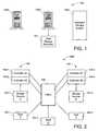
- FIG. 1is a diagrammatical depiction of exemplary operating systems in which various embodiments of the present invention can be employed.
- FIG. 2is a top level functional block depiction of a computer-based system characterized as a wide-area network utilizing mass storage.
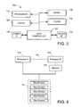
- FIG. 3provides a functional block diagram illustrating a selected one of the controllers of FIG. 2 .
- FIG. 4provides a functional block diagram illustrating a dual-processor arrangement in accordance with embodiments of the present invention.
- FIG. 5diagrammatically depicts a drive array storage map and grid storage architecture
- FIG. 6diagrammatically illustrates metadata in the form of a storage allocation map (SAM) and storage allocation descriptor (SAD).
- SAMstorage allocation map
- SADstorage allocation descriptor
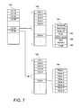
- FIG. 7diagrammatically depicts metadata in the form of a logical device allocation map (LDAM).
- LDAMlogical device allocation map
- FIG. 8diagrammatically depicts metadata in the form of a logical device allocation descriptor array (LDAD).
- LDADlogical device allocation descriptor array
- FIG. 9diagrammatically depicts metadata in the form of a grid group allocation table GGAT).
- FIG. 10diagrammatically depicts metadata stored within the system configuration information area of a drive array and metadata and portions of metadata stored in memory.
- FIG. 11is a flowchart illustrating steps for practicing a method of allocating storage capacity in accordance with embodiments of the present invention.
- FIG. 12diagrammatically depicts a configuration update request packet.
- FIG. 1depicts exemplary operating systems in which embodiments of the present invention can be employed, such as in a computer 100 A, or in a server 100 B with internal or attached data storage devices 101 , or in an intelligent storage system 100 C.
- Intelligent storage system 100 Cis representative of storage systems that can have intelligent controllers and interfaces and that can have one or more data storage arrays.
- Operating systems 100each contain at least one central processing unit (CPU), a plurality of data storage devices 101 defining a data storage capacity, and metadata describing the configuration of the data storage capacity.
- configurationit is meant that a description is provided to the system 100 regarding whether particular portions of the storage capacity are being used to store data, or “allocated” space, as opposed to the portions that are available for storing data, or “allocatable” space.
- embodiments of the present inventioncan be used in a system 100 that includes at least two data storage devices 101 and one controller.
- Embodiments of the present inventioncan be employed in simple systems having little or no fault tolerance redundancy to highly redundant systems having no single point of failure.
- FIG. 2shows a computer-based system 100 C characterized as a wide area network (WAN) utilizing mass storage.
- WANwide area network
- the system 100 Cincludes a number of host computers 102 , respectively identified as hosts A, B, and C.
- the host computers 102interact with each other as well as with a pair of data storage arrays 104 (denoted A and B, respectively) via a fabric 106 .
- the fabric 106is preferably characterized as fibre-channel based switching network, although other configurations can be utilized as well including the Internet.
- Each array 104includes a pair of controllers 108 (denoted A 1 , A 2 and B 1 , B 2 ) and a set of data storage devices 101 preferably characterized as disc drives operated as a RAID.
- the controllers 108 and data storage devices 101preferably utilize a fault tolerant arrangement so that the various controllers 108 utilize parallel, redundant links and at least some of the user data stored by the system 100 C is stored in a redundant format within at least one set of the data storage devices 101 .
- a host computer 102 and the A data storage array 104can be physically located at a first site, the B host computer 102 and B storage array 104 can be physically located at a second site, and the C host computer 102 can be yet at a third site, although such is merely illustrative and not limiting.
- FIG. 3illustrates a selected one of the controllers 108 in greater detail.
- the controller 108can be embodied in a single integrated circuit, or distributed among a number of discrete circuits as desired.
- a main processor 112preferably characterized as a programmable, computer processor, provides control in accordance with programming steps and processing data preferably stored in non-volatile memory 114 (such as flash memory or similar) and in dynamic random access memory (DRAM) 116 .
- non-volatile memory 114such as flash memory or similar
- DRAMdynamic random access memory
- a fabric interface (I/F) circuit 118communicates with the other controllers 108 and the host computers 102 via the fabric 106 , and a device I/F circuit 122 communicates with the storage devices 101 .
- the I/F circuits 118 , 122 and a path controller 120form a communication path to pass commands and data between the storage array 104 and the host 102 , such as by employing the cache memory 124 .
- the path controller 120 and the I/F circuits 118 , 122can be unitarily constructed.
- the data storage capacity of an array 104is organized into logical devices that can be written to and read from the array 104 .
- System configuration informationdefines the relationship between user data, including any associated parity and mirror data, with the respective storage locations.
- the system configuration informationfurthermore identifies the relationship between blocks of storage capacity allocated to user data and the memory storage locations, such as logical block addresses (LBA).
- LBAlogical block addresses
- the system configuration informationcan furthermore include virtualization by defining virtual block addresses that are mapped to logical block addresses.
- System configuration informationis changed in response to a configuration change request from the system 100 C.
- storage capacitycan be allocated, such as when saving new files or enlarging existing files, or storage capacity can be deallocated, such as when deleting files or reducing the size of existing files.
- allocationmeans either an allocation or deallocation of storage capacity.
- System metadatais resultant data defining file allocation information states and other data structures that support allocation processes.
- FIG. 4depicts illustrative embodiments of the present invention employing a means for updating the system configuration information by utilizing multiple processors that share the operational steps associated with responding to the configuration change request.
- the processor 112is adapted for identifying candidate system configuration information associated with a configuration change request, as described below.
- candidate system configuration informationis a portion of the system configuration information that is associated with the configuration change request, such as by a logical device (LD), for example a logical disc, to which storage capacity is to be allocated.
- the candidate system configuration informationcould include all storage units that have been allocated to the particular LD associated with a configuration change request.
- the processor 112is coupled to a processor 130 such as by a bus 132 or other connection providing communication between the two.
- the processor 130is preferably a dedicated metadata access processor (MAP).
- a memory 134can be read from and written to by the processor 130 .
- the processor 112can transfer system configuration information, preferably in the form of metadata, from the data storage devices 101 to the memory 134 .
- Memory 134can be any type of memory such as DRAM, SRAM, or other memory, and can include parity, ECC, or other data encoding.
- memory 134comprises a write-back cache memory with backup power, as may be supplied from a battery, for example.
- Processor 112can page system configuration information (transfer a block of infoiniation) from drive array 104 into memory 134 using programmed I/O, a DMA controller, or other hardware and/or software methods.
- processor 130can be part of an intelligent controller such as a data storage device controller, interface controller, or other controller. Some embodiments can comprise the processor 112 and multiple intelligent controllers, each having an associated memory.
- system configuration information defining the allocation of storage capacitycan be stored in the array 104 .
- the form and content of the system configuration informationcan vary depending upon the organization of storage capacity into LDs and the manner in which user data and redundant data, such as mirror data or parity data, are distributed among the data storage devices 101 .
- Embodiments of the present inventionfurnish an architecture and methods for creating and modifying system configuration information.
- the system configuration informationcan control hardware configurations, such as operating modes of devices and peripherals, and/or software configurations including file systems and allocation of storage capacity in data storage systems.
- the following figuresprovide examples of system configuration information and processing thereof for a grid architecture storage system. However, applications of embodiments of the present invention are not limited to specific storage system or system configuration information formats.
- FIG. 5depicts an array map 140 of a grid storage architecture.
- the array map 140represents the storage capacity of an array 104 , which is used for storing either user data 142 or system configuration information 144 .
- the array map 140represents a plurality of storage grids 146 , each having a predetermined storage capacity made from some or all of the data storage devices 101 in the array 104 .
- the grid 146comprises an allocatable amount of storage distributed across each of a plurality of the data storage devices 101 in an array 104 .
- a grid 146 containing only user data 142is termed a storage unit (SU). Fault tolerance can be provided for data stored in an SU through redundant information, such as parity data or mirror data, which is preferably stored in other grids 146 .
- An SU that is associated with fault tolerance information contained in one or more other grids 146is termed a “reliable storage unit” (RSU).
- RSUreliable storage unit
- the term “SU”contemplates a preselected user data storage capacity with or without associated fault tolerance information. That is, the term “SU” can mean an SU containing user data without any associated fault tolerance information, and the term “SU” can in equivalent alternative embodiments mean an RSU.
- a plurality of grids 146can be grouped into a grid group (sometimes referred to as a “sheet”) 148 .
- the sheet 148can be allocated to a logical device (LD), and individual grids 146 within the allocated sheet 148 can further be assigned/unassigned to/from the LD in response to system configuration change requests.
- Grids 146 in the array map 140can be sequentially numbered or otherwise assigned a number or identifier that uniquely identifies them.
- the array map 140can be viewed as comprising a plurality of sheets 148 , with each sheet 148 comprising a plurality of grids 146 .
- User data 142including redundant data, if any, and system configuration information 144 can be stored within the grids 146 , and thus within the sheets 148 .
- a plurality of array maps 140can be employed if the system 100 C has a plurality of arrays 104 or other organization of data storage devices 101 .
- system metadatacan be stored in one or more arrays 104 .
- FIG. 6diagrammatically illustrates a storage allocation map (SAM) 160 and a storage allocation descriptor (SAD) 162 .
- the SAM 160is an array having one indicator bit for each sheet 148 in the array map 140 ( FIG. 5 ).
- the bit for a sheet 148is set to a first value if the respective sheet 148 is allocatable, and is set to a second value if the respective sheet 148 has been allocated to an LD.
- SAM 160is a map designating where allocatable sheets 148 exist in an array 104 .
- the SAD 162provides a summary of the information contained in the SAM 160 .
- the SAD 162can include a count of the total number of sheets 164 and the number of allocatable sheets 166 in the SAM 160 .
- the SAD 162can also provide a summary of the total number of allocatable sheets 168 , 170 within predefined zones 172 , 174 of the SAM 160 .
- zone 1 allocatable sheets 168contains the number of allocatable sheets 148 within zone 1 ( 172 ) of the SAM 160 .
- FIG. 7depicts metadata utilized in allocating storage capacity to a designated LD in a grid-based data storage system.
- the metadatacomprises a logical device allocation map (LDAM) 180 that has a corresponding logical device grid table (LDGT) 182 for each LD listed in the LDAM 180 .
- LDAMlogical device allocation map
- LDGTlogical device grid table
- sheets 148can be allocated to an LD and grids 146 within the sheet 148 assigned to the LD.
- the LDGT 182is a listing of grids 146 assigned to the respective LD.
- the LDAM 180can be implemented as a flat map with an offset into the map determined from an LD number to locate the LDGT 182 for that LD number.
- the LDAM 180can be implemented as a list of indices each pointing to an LDGT 182 .
- Other addressing methodscan be used as well.
- the LDAM 180is not limited to a specific number of LDGTs 182 .
- Each LDGT 182can include a grid entry descriptor 184 that specifies a grid number 186 , and can contain additional information such as RAID level 188 , array ID 190 (such as if the storage system comprises a plurality of arrays 104 ) and other information, such as illustrated.
- the LDAM 180can also contain an RBit Array (RBA) 192 for each LD that contains RBits 194 that can be employed to indicate if a portion of a grid 146 has been accessed or utilized.
- Rbits 194can be employed to indicate if a portion of a grid 146 has been copied.
- FIG. 8depicts a logical device allocation descriptor array (LDAD) 200 , which provides summary information of the sheets 148 allocated and the grids 146 assigned to a particular LD.
- the LDAD 200can comprise a flat map where an offset into the map is determined from an LD number to access LDAD contents 202 for a given LD.
- the LDAD contents 202can comprise a count of the number of sheets allocated 204 to the LD, a count of the number of grids assigned 206 to the LD, and can include other information such as present sheet 208 and last sheet 210 , as can be employed for assigning additional grids 146 from allocated sheets 148 or for de-allocating grids 146 , for example.
- FIG. 9further depicts metadata comprising a grid group allocation table (GGAT) 220 .
- GGAT 220can be a flat map with an offset into the map determined from a sheet number to locate a respective GGAT entry 222 .
- Each GGAT entry 222can contain an LD number 224 to which the sheet 148 is allocated (or another number indicating that the sheet 148 has not been allocated), can include a RAID level 226 for the sheet 148 , and can contain a grid map 228 indicating which grids 146 within the sheet 148 have been assigned to the LD.
- FIG. 10depicts illustrative data structures stored within system configuration information 144 area of array 104 , and data structures and portions of data structures stored in memory 134 .
- a system configuration information map 230can include illustrative data structures from above, such as GGAT 220 , LDAM 180 , LDAD 200 , SAM 160 and SAD 162 .
- a memory map 232depicts data structures and portions of data structures copied from array 104 and stored in memory 134 .
- the structurescan include GGAT 220 , LDGT 182 for a specified LD, LDAD entry 202 for the specified LD, SAM 160 , and SAD 162 .
- Memory 134can also contain other information 234 that can include an update record 236 .
- the update record 236can comprise memory allocation information comprising that portion of the candidate system configuration information that is changed as a result of completing the configuration update request.
- the memory allocation informationcan be combined with the prior state of the system configuration information to obtain the subsequent state of the system configuration information.
- the subsequent state of the system configuration informationcan be ascertained by viewing the prior state of the system configuration information as modified by the memory allocation information.
- Processor 112identifies the candidate system configuration information associated with the configuration change request, by determining which data structures, or portions thereof, are paged into memory 134 .
- FIG. 10is merely illustrative of applicable system configuration information. The format of this information can vary depending on the storage system configuration. Data structures can be stored in memory 134 in an order other than that depicted.
- FIG. 11illustrates a method 240 for updating system configuration information in accordance with embodiments of the present invention.
- allocationincludes both allocating storage capacity, such as when saving a file to memory, and deallocating storage capacity, such as when deleting a file from memory.
- the processor 112detects a configuration change request, such as might be associated with events such as a request that a new LD be created, a request that the size of an existing LD be increased, a request to change the data storage format of an existing LD to a format utilizing greater storage capacity, or the like.
- a configuration change requestsuch as might be associated with events such as a request that a new LD be created, a request that the size of an existing LD be increased, a request to change the data storage format of an existing LD to a format utilizing greater storage capacity, or the like.
- the configuration change requestis associated with a request for creating a new LD.
- the processor 112selects candidate system configuration information stored in array 104 that will include the system configuration information affected by processing the configuration change request. This can include selecting an LDGT 182 from LDAM 180 and LDAD entry 202 from LDAD 200 using the LD number of the LD to be created.
- the candidate system configuration information stored in array 104is transferred to memory 134 under control of processor 112 . This can comprise programmed I/O, programming a DMA controller, configuring or instructing another processor to perform the transfer, or any other transfer methods.
- memory 134is a cache memory and the candidate system configuration information is paged into the cache.
- an update requestis created, such as by processor 112 , and issued to processor 130 .
- the update requestspecifies the type of operation to be performed by processor 130 and can be in the form, as illustrated in FIG. 12 , of a request packet 250 containing an opcode 252 , an LD number 254 , a storage format identifier 256 , and an amount of storage to be allocated 258 . From the opcode and/or other information contained in the update request, processor 130 determines the operational steps necessary to perform an allocation in satisfying the configuration change request.
- the processor 130identifies allocatable storage capacity that is sufficient to satisfy the configuration change request, such as by reading allocatable grid group zone counts 168 , 170 ( FIG. 6 ) contained within SAD 162 .
- Thispermits an efficient manner of identifying one or more zones of the SAM 160 from which sheets 184 with sufficient allocatable storage capacity exists.
- One or more sheets 184 corresponding to “allocatable” bits within the SAM 160are selected.
- the position of each bit within the SAM 160corresponds to a sheet number.
- the number of the first grid 146 within a sheet 148can be determined by multiplying the sheet number by the number of grids 146 in a sheet 148 and adding an offset, if any.
- an update recordcan be created. For example, for each sheet 148 selected in step 260 , a GGAT entry 222 is created and stored in update record 236 ( FIG. 10 ). Grids 146 from selected sheets 148 are then assigned to the LD. Depending on the amount of storage requested, one or more sheets 148 can be selected and some or all of the grids 146 within a sheet assigned to the LD. An LDGT 182 for the LD that contains the grid number 186 is created and stored in update record 236 ( FIG. 10 ). Updated values for SAM 160 and SAD 162 , reflecting the allocation of one or more sheets 148 , are calculated and stored in update record 236 .
- the update record 236can be in the form of a recovery record, which is useful in providing an idempotent update of the configuration information if the updating process is interrupted during execution.
- the processor 130updates system configuration information data structures stored in memory 134 using the update record 236 .
- this updatingis an atomic process that is not interrupted by any other process.
- the processor 130disables processing of input-output interrupts during the updating process.
- the processor 130can return a completion response to processor 112 indicating that the update request has been processed.
- FIG. 11illustrates steps performed to allocate storage capacity using two processors.
- a configuration update request packetcan be employed for a range of operations that can include, but are not limited to, creation of a new LD, increasing the size of an existing LD, converting the format of an LD, reducing the size of an LD, and deleting an LD.
- the steps of the method 240can likewise be performed in deallocating storage capacity.
- FIG. 12depicts an illustrative update request packet 250 that can be sent to the processor 130 .
- the update request 250can be of a predefined size or can be of variable size depending upon the type of operation.
- Opcode 252comprises a value designating the type of operation to be performed. Table 1 below illustrates exemplary opcodes.
- opcodes 252can be defined for other operations.
- LD number 254can comprise an LD number or other LD identifier.
- Storage format 256specifies the storage format that can include, but is not limited to, RAID formats.
- Storage capacity 258specifies an amount of storage to be allocated. Storage capacity 258 can be specified in blocks, bytes, grids, grid groups, or other units.
- embodiments of the present inventionprovide a system and method for updating system configuration information that reduces the workload on a first processor by performing some tasks on a second processor. Preloading a memory accessible by the second processor with configuration information to be updated allows updates to be performed in an atomic manner since no other I/Os are required.
- Computer program code for the second processorcan be simplified by transferring types of system configuration information to predefined locations within the cache memory. Frequently accessed system configuration information, such as SAM 160 and SAD 162 , for example, can be kept resident in the cache.
- Use of a write-back cache memoryallows updated system configuration information to be quickly available to the system for file access without the delay of I/Os to write configuration information back to the array.
- the metadatacan be highly organized in the write-back cache memory. Some elements of the metadata can be preloaded and always existent, while other elements can be paged into cache as needed by high level policy software.
- the high level policy softwaredetermines what metadata is needed in cache, and then coordinates the I/Os to accomplish the determination. Then the high level policy software can issue the request packet in very dense form (such as virtualization active context entry (VACE)) to the operational processor (such as MAP).
- VACEvirtualization active context entry
- the operational processorcarries out the actual metadata manipulation, updating discontiguous pieces of metadata with only memory references, and without needing to understand how the high level policy software will use the metadata changes.
- the atomicityis achieved by processing only a single metadata update at a time, which is possible because by definition no I/Os are necessary for the operational processor to perform a request.
- configuration change requestscan be employed to update other system configuration information including but not limited to hardware device configuration and software configurations, such as passwords, for example.
Landscapes
- Engineering & Computer Science (AREA)
- Theoretical Computer Science (AREA)
- Physics & Mathematics (AREA)
- General Engineering & Computer Science (AREA)
- General Physics & Mathematics (AREA)
- Human Computer Interaction (AREA)
- Software Systems (AREA)
- Computer Hardware Design (AREA)
- Information Retrieval, Db Structures And Fs Structures Therefor (AREA)
Abstract
Description
| TABLE 1 | |
| Opcode | Operation |
| 0x0000 | Illegal/Reserved OpCode |
| 0x0001 | Create New LD |
| 0x0002 | Expand Existing LD |
| 0x0003 | Reduce Existing LD |
| 0x0004 | Delete LD |
| 0x0005 | Convert LD Format |
Claims (17)
Priority Applications (1)
| Application Number | Priority Date | Filing Date | Title |
|---|---|---|---|
| US10/969,648US8131969B2 (en) | 2004-10-20 | 2004-10-20 | Updating system configuration information |
Applications Claiming Priority (1)
| Application Number | Priority Date | Filing Date | Title |
|---|---|---|---|
| US10/969,648US8131969B2 (en) | 2004-10-20 | 2004-10-20 | Updating system configuration information |
Publications (2)
| Publication Number | Publication Date |
|---|---|
| US20060085626A1 US20060085626A1 (en) | 2006-04-20 |
| US8131969B2true US8131969B2 (en) | 2012-03-06 |
Family
ID=36182174
Family Applications (1)
| Application Number | Title | Priority Date | Filing Date |
|---|---|---|---|
| US10/969,648Active2030-02-08US8131969B2 (en) | 2004-10-20 | 2004-10-20 | Updating system configuration information |
Country Status (1)
| Country | Link |
|---|---|
| US (1) | US8131969B2 (en) |
Cited By (1)
| Publication number | Priority date | Publication date | Assignee | Title |
|---|---|---|---|---|
| US9727426B2 (en) | 2015-02-25 | 2017-08-08 | Microsoft Technology Licensing, Llc | Using an overinclusive write record to track and write changes to a storage system |
Families Citing this family (34)
| Publication number | Priority date | Publication date | Assignee | Title |
|---|---|---|---|---|
| JP4338982B2 (en)* | 2003-01-27 | 2009-10-07 | ユニ・チャーム株式会社 | Rotary cutter and method for producing fiber product using the same |
| US8019938B2 (en) | 2006-12-06 | 2011-09-13 | Fusion-I0, Inc. | Apparatus, system, and method for solid-state storage as cache for high-capacity, non-volatile storage |
| US8935302B2 (en)* | 2006-12-06 | 2015-01-13 | Intelligent Intellectual Property Holdings 2 Llc | Apparatus, system, and method for data block usage information synchronization for a non-volatile storage volume |
| US8489817B2 (en) | 2007-12-06 | 2013-07-16 | Fusion-Io, Inc. | Apparatus, system, and method for caching data |
| US7836226B2 (en) | 2007-12-06 | 2010-11-16 | Fusion-Io, Inc. | Apparatus, system, and method for coordinating storage requests in a multi-processor/multi-thread environment |
| US9519540B2 (en) | 2007-12-06 | 2016-12-13 | Sandisk Technologies Llc | Apparatus, system, and method for destaging cached data |
| JP5999645B2 (en) | 2009-09-08 | 2016-10-05 | ロンギチュード エンタープライズ フラッシュ エスエイアールエル | Apparatus, system, and method for caching data on a solid state storage device |
| US9122579B2 (en) | 2010-01-06 | 2015-09-01 | Intelligent Intellectual Property Holdings 2 Llc | Apparatus, system, and method for a storage layer |
| KR101769883B1 (en)* | 2009-09-09 | 2017-08-21 | 샌디스크 테크놀로지스 엘엘씨 | Apparatus, system, and method for allocating storage |
| JP5494208B2 (en)* | 2010-05-12 | 2014-05-14 | 富士ゼロックス株式会社 | Image forming apparatus and control program therefor |
| US20120239860A1 (en) | 2010-12-17 | 2012-09-20 | Fusion-Io, Inc. | Apparatus, system, and method for persistent data management on a non-volatile storage media |
| US8874823B2 (en) | 2011-02-15 | 2014-10-28 | Intellectual Property Holdings 2 Llc | Systems and methods for managing data input/output operations |
| US9003104B2 (en) | 2011-02-15 | 2015-04-07 | Intelligent Intellectual Property Holdings 2 Llc | Systems and methods for a file-level cache |
| US9201677B2 (en) | 2011-05-23 | 2015-12-01 | Intelligent Intellectual Property Holdings 2 Llc | Managing data input/output operations |
| WO2012116369A2 (en) | 2011-02-25 | 2012-08-30 | Fusion-Io, Inc. | Apparatus, system, and method for managing contents of a cache |
| US8966191B2 (en) | 2011-03-18 | 2015-02-24 | Fusion-Io, Inc. | Logical interface for contextual storage |
| US9563555B2 (en) | 2011-03-18 | 2017-02-07 | Sandisk Technologies Llc | Systems and methods for storage allocation |
| US9274937B2 (en) | 2011-12-22 | 2016-03-01 | Longitude Enterprise Flash S.A.R.L. | Systems, methods, and interfaces for vector input/output operations |
| US9251086B2 (en) | 2012-01-24 | 2016-02-02 | SanDisk Technologies, Inc. | Apparatus, system, and method for managing a cache |
| US10359972B2 (en) | 2012-08-31 | 2019-07-23 | Sandisk Technologies Llc | Systems, methods, and interfaces for adaptive persistence |
| US9116812B2 (en) | 2012-01-27 | 2015-08-25 | Intelligent Intellectual Property Holdings 2 Llc | Systems and methods for a de-duplication cache |
| US9612966B2 (en) | 2012-07-03 | 2017-04-04 | Sandisk Technologies Llc | Systems, methods and apparatus for a virtual machine cache |
| US10339056B2 (en) | 2012-07-03 | 2019-07-02 | Sandisk Technologies Llc | Systems, methods and apparatus for cache transfers |
| US10318495B2 (en) | 2012-09-24 | 2019-06-11 | Sandisk Technologies Llc | Snapshots for a non-volatile device |
| US10509776B2 (en) | 2012-09-24 | 2019-12-17 | Sandisk Technologies Llc | Time sequence data management |
| US9842053B2 (en) | 2013-03-15 | 2017-12-12 | Sandisk Technologies Llc | Systems and methods for persistent cache logging |
| US10102144B2 (en) | 2013-04-16 | 2018-10-16 | Sandisk Technologies Llc | Systems, methods and interfaces for data virtualization |
| US10558561B2 (en) | 2013-04-16 | 2020-02-11 | Sandisk Technologies Llc | Systems and methods for storage metadata management |
| US9842128B2 (en) | 2013-08-01 | 2017-12-12 | Sandisk Technologies Llc | Systems and methods for atomic storage operations |
| US10019320B2 (en) | 2013-10-18 | 2018-07-10 | Sandisk Technologies Llc | Systems and methods for distributed atomic storage operations |
| US10073630B2 (en) | 2013-11-08 | 2018-09-11 | Sandisk Technologies Llc | Systems and methods for log coordination |
| CN104571960B (en)* | 2014-12-30 | 2018-01-16 | 华为技术有限公司 | I/O request dispensing device and method, main frame, storage array and computer system |
| US9946607B2 (en) | 2015-03-04 | 2018-04-17 | Sandisk Technologies Llc | Systems and methods for storage error management |
| CN113568562A (en)* | 2020-04-28 | 2021-10-29 | 华为技术有限公司 | Storage system, memory management method and management node |
Citations (36)
| Publication number | Priority date | Publication date | Assignee | Title |
|---|---|---|---|---|
| US4847807A (en) | 1986-09-11 | 1989-07-11 | Hughes Aircraft Company | Multiple disk memory access arrangement for gridded type data |
| US5285451A (en) | 1990-04-06 | 1994-02-08 | Micro Technology, Inc. | Failure-tolerant mass storage system |
| US5325363A (en) | 1992-05-11 | 1994-06-28 | Tandem Computers Incorporated | Fault tolerant power supply for an array of storage devices |
| US5412661A (en) | 1992-10-06 | 1995-05-02 | International Business Machines Corporation | Two-dimensional disk array |
| US5519844A (en) | 1990-11-09 | 1996-05-21 | Emc Corporation | Logical partitioning of a redundant array storage system |
| US5537567A (en) | 1994-03-14 | 1996-07-16 | International Business Machines Corporation | Parity block configuration in an array of storage devices |
| US5544339A (en) | 1992-01-07 | 1996-08-06 | Mitsubishi Denki Kabushiki Kaisha | Array of disk drives with redundant channels |
| US5568629A (en) | 1991-12-23 | 1996-10-22 | At&T Global Information Solutions Company | Method for partitioning disk drives within a physical disk array and selectively assigning disk drive partitions into a logical disk array |
| US5632027A (en) | 1995-09-14 | 1997-05-20 | International Business Machines Corporation | Method and system for mass storage device configuration management |
| US5671349A (en) | 1994-12-06 | 1997-09-23 | Hitachi Computer Products America, Inc. | Apparatus and method for providing data redundancy and reconstruction for redundant arrays of disk drives |
| US5682509A (en) | 1995-12-13 | 1997-10-28 | Ast Research, Inc. | Bus interface to a RAID architecture |
| US5729763A (en) | 1995-08-15 | 1998-03-17 | Emc Corporation | Data storage system |
| US5774643A (en)* | 1995-10-13 | 1998-06-30 | Digital Equipment Corporation | Enhanced raid write hole protection and recovery |
| US5790775A (en)* | 1995-10-23 | 1998-08-04 | Digital Equipment Corporation | Host transparent storage controller failover/failback of SCSI targets and associated units |
| US5812754A (en) | 1996-09-18 | 1998-09-22 | Silicon Graphics, Inc. | Raid system with fibre channel arbitrated loop |
| US5960169A (en) | 1997-02-27 | 1999-09-28 | International Business Machines Corporation | Transformational raid for hierarchical storage management system |
| US6101615A (en) | 1998-04-08 | 2000-08-08 | International Business Machines Corporation | Method and apparatus for improving sequential writes to RAID-6 devices |
| US6154853A (en) | 1997-03-26 | 2000-11-28 | Emc Corporation | Method and apparatus for dynamic sparing in a RAID storage system |
| US6195695B1 (en) | 1998-10-27 | 2001-02-27 | International Business Machines Corporation | Data processing system and method for recovering from system crashes |
| US6219753B1 (en) | 1999-06-04 | 2001-04-17 | International Business Machines Corporation | Fiber channel topological structure and method including structure and method for raid devices and controllers |
| US6247157B1 (en) | 1998-05-13 | 2001-06-12 | Intel Corporation | Method of encoding data signals for storage |
| US6327672B1 (en) | 1998-12-31 | 2001-12-04 | Lsi Logic Corporation | Multiple drive failure tolerant raid system |
| US6338126B1 (en) | 1999-12-06 | 2002-01-08 | Legato Systems, Inc. | Crash recovery without complete remirror |
| US6353895B1 (en) | 1998-02-19 | 2002-03-05 | Adaptec, Inc. | RAID architecture with two-drive fault tolerance |
| US6453428B1 (en) | 1998-07-17 | 2002-09-17 | Adaptec, Inc. | Dual-drive fault tolerant method and system for assigning data chunks to column parity sets |
| US6457140B1 (en) | 1997-12-11 | 2002-09-24 | Telefonaktiebolaget Lm Ericsson | Methods and apparatus for dynamically isolating fault conditions in a fault tolerant multi-processing environment |
| US6473830B2 (en) | 1998-06-05 | 2002-10-29 | International Business Machines Corporation | System and method for organizing data stored in a log structured array |
| US6502166B1 (en) | 1999-12-29 | 2002-12-31 | International Business Machines Corporation | Method and apparatus for distributing data across multiple disk drives |
| US6529994B1 (en) | 1994-07-19 | 2003-03-04 | Sarnoff Corporation | Method of striping data onto a storage array |
| US6557123B1 (en) | 1999-08-02 | 2003-04-29 | Inostor Corporation | Data redundancy methods and apparatus |
| US6574687B1 (en) | 1999-12-29 | 2003-06-03 | Emc Corporation | Fibre channel data storage system |
| US6675176B1 (en) | 1998-09-18 | 2004-01-06 | Fujitsu Limited | File management system |
| US6675318B1 (en) | 2000-07-25 | 2004-01-06 | Sun Microsystems, Inc. | Two-dimensional storage array with prompt parity in one dimension and delayed parity in a second dimension |
| US20040049770A1 (en)* | 2002-09-10 | 2004-03-11 | Georgios Chrysanthakopoulos | Infrastructure for generating a downloadable, secure runtime binary image for a secondary processor |
| US20040133506A1 (en)* | 2000-11-17 | 2004-07-08 | Arman Glodjo | Global electronic trading system |
| US7353259B1 (en)* | 2002-03-07 | 2008-04-01 | Cisco Technology, Inc. | Method and apparatus for exchanging configuration information between nodes operating in a master-slave configuration |
- 2004
- 2004-10-20USUS10/969,648patent/US8131969B2/enactiveActive
Patent Citations (38)
| Publication number | Priority date | Publication date | Assignee | Title |
|---|---|---|---|---|
| US4847807A (en) | 1986-09-11 | 1989-07-11 | Hughes Aircraft Company | Multiple disk memory access arrangement for gridded type data |
| US5285451A (en) | 1990-04-06 | 1994-02-08 | Micro Technology, Inc. | Failure-tolerant mass storage system |
| US5708769A (en) | 1990-11-09 | 1998-01-13 | Emc Corporation | Logical partitioning of a redundant array storage system |
| US5519844A (en) | 1990-11-09 | 1996-05-21 | Emc Corporation | Logical partitioning of a redundant array storage system |
| US6154854A (en) | 1990-11-09 | 2000-11-28 | Emc Corporation | Logical partitioning of a redundant array storage system |
| US5568629A (en) | 1991-12-23 | 1996-10-22 | At&T Global Information Solutions Company | Method for partitioning disk drives within a physical disk array and selectively assigning disk drive partitions into a logical disk array |
| US5544339A (en) | 1992-01-07 | 1996-08-06 | Mitsubishi Denki Kabushiki Kaisha | Array of disk drives with redundant channels |
| US5325363A (en) | 1992-05-11 | 1994-06-28 | Tandem Computers Incorporated | Fault tolerant power supply for an array of storage devices |
| US5412661A (en) | 1992-10-06 | 1995-05-02 | International Business Machines Corporation | Two-dimensional disk array |
| US5537567A (en) | 1994-03-14 | 1996-07-16 | International Business Machines Corporation | Parity block configuration in an array of storage devices |
| US6529994B1 (en) | 1994-07-19 | 2003-03-04 | Sarnoff Corporation | Method of striping data onto a storage array |
| US5671349A (en) | 1994-12-06 | 1997-09-23 | Hitachi Computer Products America, Inc. | Apparatus and method for providing data redundancy and reconstruction for redundant arrays of disk drives |
| US5729763A (en) | 1995-08-15 | 1998-03-17 | Emc Corporation | Data storage system |
| US5632027A (en) | 1995-09-14 | 1997-05-20 | International Business Machines Corporation | Method and system for mass storage device configuration management |
| US5774643A (en)* | 1995-10-13 | 1998-06-30 | Digital Equipment Corporation | Enhanced raid write hole protection and recovery |
| US5790775A (en)* | 1995-10-23 | 1998-08-04 | Digital Equipment Corporation | Host transparent storage controller failover/failback of SCSI targets and associated units |
| US5682509A (en) | 1995-12-13 | 1997-10-28 | Ast Research, Inc. | Bus interface to a RAID architecture |
| US5812754A (en) | 1996-09-18 | 1998-09-22 | Silicon Graphics, Inc. | Raid system with fibre channel arbitrated loop |
| US5960169A (en) | 1997-02-27 | 1999-09-28 | International Business Machines Corporation | Transformational raid for hierarchical storage management system |
| US6154853A (en) | 1997-03-26 | 2000-11-28 | Emc Corporation | Method and apparatus for dynamic sparing in a RAID storage system |
| US6457140B1 (en) | 1997-12-11 | 2002-09-24 | Telefonaktiebolaget Lm Ericsson | Methods and apparatus for dynamically isolating fault conditions in a fault tolerant multi-processing environment |
| US6353895B1 (en) | 1998-02-19 | 2002-03-05 | Adaptec, Inc. | RAID architecture with two-drive fault tolerance |
| US6101615A (en) | 1998-04-08 | 2000-08-08 | International Business Machines Corporation | Method and apparatus for improving sequential writes to RAID-6 devices |
| US6247157B1 (en) | 1998-05-13 | 2001-06-12 | Intel Corporation | Method of encoding data signals for storage |
| US6473830B2 (en) | 1998-06-05 | 2002-10-29 | International Business Machines Corporation | System and method for organizing data stored in a log structured array |
| US6453428B1 (en) | 1998-07-17 | 2002-09-17 | Adaptec, Inc. | Dual-drive fault tolerant method and system for assigning data chunks to column parity sets |
| US6675176B1 (en) | 1998-09-18 | 2004-01-06 | Fujitsu Limited | File management system |
| US6195695B1 (en) | 1998-10-27 | 2001-02-27 | International Business Machines Corporation | Data processing system and method for recovering from system crashes |
| US6327672B1 (en) | 1998-12-31 | 2001-12-04 | Lsi Logic Corporation | Multiple drive failure tolerant raid system |
| US6219753B1 (en) | 1999-06-04 | 2001-04-17 | International Business Machines Corporation | Fiber channel topological structure and method including structure and method for raid devices and controllers |
| US6557123B1 (en) | 1999-08-02 | 2003-04-29 | Inostor Corporation | Data redundancy methods and apparatus |
| US6338126B1 (en) | 1999-12-06 | 2002-01-08 | Legato Systems, Inc. | Crash recovery without complete remirror |
| US6502166B1 (en) | 1999-12-29 | 2002-12-31 | International Business Machines Corporation | Method and apparatus for distributing data across multiple disk drives |
| US6574687B1 (en) | 1999-12-29 | 2003-06-03 | Emc Corporation | Fibre channel data storage system |
| US6675318B1 (en) | 2000-07-25 | 2004-01-06 | Sun Microsystems, Inc. | Two-dimensional storage array with prompt parity in one dimension and delayed parity in a second dimension |
| US20040133506A1 (en)* | 2000-11-17 | 2004-07-08 | Arman Glodjo | Global electronic trading system |
| US7353259B1 (en)* | 2002-03-07 | 2008-04-01 | Cisco Technology, Inc. | Method and apparatus for exchanging configuration information between nodes operating in a master-slave configuration |
| US20040049770A1 (en)* | 2002-09-10 | 2004-03-11 | Georgios Chrysanthakopoulos | Infrastructure for generating a downloadable, secure runtime binary image for a secondary processor |
Cited By (1)
| Publication number | Priority date | Publication date | Assignee | Title |
|---|---|---|---|---|
| US9727426B2 (en) | 2015-02-25 | 2017-08-08 | Microsoft Technology Licensing, Llc | Using an overinclusive write record to track and write changes to a storage system |
Also Published As
| Publication number | Publication date |
|---|---|
| US20060085626A1 (en) | 2006-04-20 |
Similar Documents
| Publication | Publication Date | Title |
|---|---|---|
| US8131969B2 (en) | Updating system configuration information | |
| CN106708425B (en) | Distributed multi-mode storage management | |
| JP5347061B2 (en) | Method and apparatus for storing data in a flash memory data storage device | |
| US10884630B2 (en) | Storage system | |
| US7831764B2 (en) | Storage system having plural flash memory drives and method for controlling data storage | |
| US8103847B2 (en) | Storage virtual containers | |
| US7882304B2 (en) | System and method for efficient updates of sequential block storage | |
| US7032070B2 (en) | Method for partial data reallocation in a storage system | |
| US7213110B2 (en) | Destaging method for storage apparatus system, and disk control apparatus, storage apparatus system and program | |
| EP2685384B1 (en) | Elastic cache of redundant cache data | |
| US8478931B1 (en) | Using non-volatile memory resources to enable a virtual buffer pool for a database application | |
| KR20150105323A (en) | Method and system for data storage | |
| EP1876519A2 (en) | Storage system and write distribution method | |
| US20080016121A1 (en) | Method, an apparatus and a system for managing a snapshot storage pool | |
| US8694563B1 (en) | Space recovery for thin-provisioned storage volumes | |
| JP2009043030A (en) | Storage system | |
| US20120260035A1 (en) | Zero rebuild extensions for raid | |
| US7032093B1 (en) | On-demand allocation of physical storage for virtual volumes using a zero logical disk | |
| US10915401B2 (en) | Data saving caused by a partial failure of the memory device | |
| CN113722131A (en) | Method and system for facilitating fast crash recovery in a storage device | |
| US7398420B2 (en) | Method for keeping snapshot image in a storage system | |
| CN109313593A (en) | Storage System | |
| US7676644B2 (en) | Data processing system, storage apparatus and management console | |
| US20170075615A1 (en) | Storage system and storage control method | |
| US11216195B1 (en) | Sharing blocks of non-volatile data storage to support cache flushes in a multi-node data storage system |
Legal Events
| Date | Code | Title | Description |
|---|---|---|---|
| AS | Assignment | Owner name:SEAGATE TECHNOLOGY LLC, CALIFORNIA Free format text:ASSIGNMENT OF ASSIGNORS INTEREST;ASSIGNORS:ROBERSON, RANDY L.;LUBBERS, CLARK EDWARD;THAKUR, TARUN;REEL/FRAME:015912/0813;SIGNING DATES FROM 20041018 TO 20041019 Owner name:SEAGATE TECHNOLOGY LLC, CALIFORNIA Free format text:ASSIGNMENT OF ASSIGNORS INTEREST;ASSIGNORS:ROBERSON, RANDY L.;LUBBERS, CLARK EDWARD;THAKUR, TARUN;SIGNING DATES FROM 20041018 TO 20041019;REEL/FRAME:015912/0813 | |
| AS | Assignment | Owner name:WELLS FARGO BANK, NATIONAL ASSOCIATION, AS COLLATERAL AGENT AND SECOND PRIORITY REPRESENTATIVE, CALIFORNIA Free format text:SECURITY AGREEMENT;ASSIGNORS:MAXTOR CORPORATION;SEAGATE TECHNOLOGY LLC;SEAGATE TECHNOLOGY INTERNATIONAL;REEL/FRAME:022757/0017 Effective date:20090507 Owner name:JPMORGAN CHASE BANK, N.A., AS ADMINISTRATIVE AGENT AND FIRST PRIORITY REPRESENTATIVE, NEW YORK Free format text:SECURITY AGREEMENT;ASSIGNORS:MAXTOR CORPORATION;SEAGATE TECHNOLOGY LLC;SEAGATE TECHNOLOGY INTERNATIONAL;REEL/FRAME:022757/0017 Effective date:20090507 Owner name:JPMORGAN CHASE BANK, N.A., AS ADMINISTRATIVE AGENT Free format text:SECURITY AGREEMENT;ASSIGNORS:MAXTOR CORPORATION;SEAGATE TECHNOLOGY LLC;SEAGATE TECHNOLOGY INTERNATIONAL;REEL/FRAME:022757/0017 Effective date:20090507 Owner name:WELLS FARGO BANK, NATIONAL ASSOCIATION, AS COLLATE Free format text:SECURITY AGREEMENT;ASSIGNORS:MAXTOR CORPORATION;SEAGATE TECHNOLOGY LLC;SEAGATE TECHNOLOGY INTERNATIONAL;REEL/FRAME:022757/0017 Effective date:20090507 | |
| AS | Assignment | Owner name:MAXTOR CORPORATION, CALIFORNIA Free format text:RELEASE;ASSIGNOR:JPMORGAN CHASE BANK, N.A., AS ADMINISTRATIVE AGENT;REEL/FRAME:025662/0001 Effective date:20110114 Owner name:SEAGATE TECHNOLOGY INTERNATIONAL, CALIFORNIA Free format text:RELEASE;ASSIGNOR:JPMORGAN CHASE BANK, N.A., AS ADMINISTRATIVE AGENT;REEL/FRAME:025662/0001 Effective date:20110114 Owner name:SEAGATE TECHNOLOGY LLC, CALIFORNIA Free format text:RELEASE;ASSIGNOR:JPMORGAN CHASE BANK, N.A., AS ADMINISTRATIVE AGENT;REEL/FRAME:025662/0001 Effective date:20110114 Owner name:SEAGATE TECHNOLOGY HDD HOLDINGS, CALIFORNIA Free format text:RELEASE;ASSIGNOR:JPMORGAN CHASE BANK, N.A., AS ADMINISTRATIVE AGENT;REEL/FRAME:025662/0001 Effective date:20110114 | |
| AS | Assignment | Owner name:THE BANK OF NOVA SCOTIA, AS ADMINISTRATIVE AGENT, CANADA Free format text:SECURITY AGREEMENT;ASSIGNOR:SEAGATE TECHNOLOGY LLC;REEL/FRAME:026010/0350 Effective date:20110118 Owner name:THE BANK OF NOVA SCOTIA, AS ADMINISTRATIVE AGENT, Free format text:SECURITY AGREEMENT;ASSIGNOR:SEAGATE TECHNOLOGY LLC;REEL/FRAME:026010/0350 Effective date:20110118 | |
| STCF | Information on status: patent grant | Free format text:PATENTED CASE | |
| FEPP | Fee payment procedure | Free format text:PAYOR NUMBER ASSIGNED (ORIGINAL EVENT CODE: ASPN); ENTITY STATUS OF PATENT OWNER: LARGE ENTITY | |
| AS | Assignment | Owner name:SEAGATE TECHNOLOGY INTERNATIONAL, CAYMAN ISLANDS Free format text:TERMINATION AND RELEASE OF SECURITY INTEREST IN PATENT RIGHTS;ASSIGNOR:WELLS FARGO BANK, NATIONAL ASSOCIATION, AS COLLATERAL AGENT AND SECOND PRIORITY REPRESENTATIVE;REEL/FRAME:030833/0001 Effective date:20130312 Owner name:SEAGATE TECHNOLOGY LLC, CALIFORNIA Free format text:TERMINATION AND RELEASE OF SECURITY INTEREST IN PATENT RIGHTS;ASSIGNOR:WELLS FARGO BANK, NATIONAL ASSOCIATION, AS COLLATERAL AGENT AND SECOND PRIORITY REPRESENTATIVE;REEL/FRAME:030833/0001 Effective date:20130312 Owner name:SEAGATE TECHNOLOGY US HOLDINGS, INC., CALIFORNIA Free format text:TERMINATION AND RELEASE OF SECURITY INTEREST IN PATENT RIGHTS;ASSIGNOR:WELLS FARGO BANK, NATIONAL ASSOCIATION, AS COLLATERAL AGENT AND SECOND PRIORITY REPRESENTATIVE;REEL/FRAME:030833/0001 Effective date:20130312 Owner name:EVAULT INC. (F/K/A I365 INC.), CALIFORNIA Free format text:TERMINATION AND RELEASE OF SECURITY INTEREST IN PATENT RIGHTS;ASSIGNOR:WELLS FARGO BANK, NATIONAL ASSOCIATION, AS COLLATERAL AGENT AND SECOND PRIORITY REPRESENTATIVE;REEL/FRAME:030833/0001 Effective date:20130312 | |
| FPAY | Fee payment | Year of fee payment:4 | |
| MAFP | Maintenance fee payment | Free format text:PAYMENT OF MAINTENANCE FEE, 8TH YEAR, LARGE ENTITY (ORIGINAL EVENT CODE: M1552); ENTITY STATUS OF PATENT OWNER: LARGE ENTITY Year of fee payment:8 | |
| MAFP | Maintenance fee payment | Free format text:PAYMENT OF MAINTENANCE FEE, 12TH YEAR, LARGE ENTITY (ORIGINAL EVENT CODE: M1553); ENTITY STATUS OF PATENT OWNER: LARGE ENTITY Year of fee payment:12 | |
| AS | Assignment | Owner name:SEAGATE TECHNOLOGY PUBLIC LIMITED COMPANY, CALIFORNIA Free format text:RELEASE BY SECURED PARTY;ASSIGNOR:THE BANK OF NOVA SCOTIA;REEL/FRAME:072193/0001 Effective date:20250303 Owner name:SEAGATE TECHNOLOGY, CALIFORNIA Free format text:RELEASE BY SECURED PARTY;ASSIGNOR:THE BANK OF NOVA SCOTIA;REEL/FRAME:072193/0001 Effective date:20250303 Owner name:SEAGATE TECHNOLOGY HDD HOLDINGS, CALIFORNIA Free format text:RELEASE BY SECURED PARTY;ASSIGNOR:THE BANK OF NOVA SCOTIA;REEL/FRAME:072193/0001 Effective date:20250303 Owner name:I365 INC., CALIFORNIA Free format text:RELEASE BY SECURED PARTY;ASSIGNOR:THE BANK OF NOVA SCOTIA;REEL/FRAME:072193/0001 Effective date:20250303 Owner name:SEAGATE TECHNOLOGY LLC, CALIFORNIA Free format text:RELEASE BY SECURED PARTY;ASSIGNOR:THE BANK OF NOVA SCOTIA;REEL/FRAME:072193/0001 Effective date:20250303 Owner name:SEAGATE TECHNOLOGY INTERNATIONAL, CAYMAN ISLANDS Free format text:RELEASE BY SECURED PARTY;ASSIGNOR:THE BANK OF NOVA SCOTIA;REEL/FRAME:072193/0001 Effective date:20250303 Owner name:SEAGATE HDD CAYMAN, CAYMAN ISLANDS Free format text:RELEASE BY SECURED PARTY;ASSIGNOR:THE BANK OF NOVA SCOTIA;REEL/FRAME:072193/0001 Effective date:20250303 Owner name:SEAGATE TECHNOLOGY (US) HOLDINGS, INC., CALIFORNIA Free format text:RELEASE BY SECURED PARTY;ASSIGNOR:THE BANK OF NOVA SCOTIA;REEL/FRAME:072193/0001 Effective date:20250303 |