US8131477B2 - Method and device for image-based biological data quantification - Google Patents
Method and device for image-based biological data quantificationDownload PDFInfo
- Publication number
- US8131477B2 US8131477B2US11/501,377US50137706AUS8131477B2US 8131477 B2US8131477 B2US 8131477B2US 50137706 AUS50137706 AUS 50137706AUS 8131477 B2US8131477 B2US 8131477B2
- Authority
- US
- United States
- Prior art keywords
- target
- concentration
- intensity
- computing
- interest
- Prior art date
- Legal status (The legal status is an assumption and is not a legal conclusion. Google has not performed a legal analysis and makes no representation as to the accuracy of the status listed.)
- Active, expires
Links
Images


Classifications
- G—PHYSICS
- G06—COMPUTING OR CALCULATING; COUNTING
- G06T—IMAGE DATA PROCESSING OR GENERATION, IN GENERAL
- G06T7/00—Image analysis
- G06T7/0002—Inspection of images, e.g. flaw detection
- G06T7/0012—Biomedical image inspection
- G—PHYSICS
- G06—COMPUTING OR CALCULATING; COUNTING
- G06T—IMAGE DATA PROCESSING OR GENERATION, IN GENERAL
- G06T2207/00—Indexing scheme for image analysis or image enhancement
- G06T2207/30—Subject of image; Context of image processing
- G06T2207/30004—Biomedical image processing
- G06T2207/30072—Microarray; Biochip, DNA array; Well plate
Definitions
- the present inventionrelates generally to a system and device for biological data quantification; and more particularly to a portable biological data quantification device.
- ELISAEnzyme Linked Immunosorbent Assay
- ELISAapplies a technique called a quantitative sandwich immunoassay. If a target such as IL-10 cytokine is present in a sample, it binds and becomes immobilized by an antibody pre-coated and “sandwiched” by biotin conjugate. To quantitatively determine the amount of IL-10 present in the sample, Avidin conjugated to Horseradish Peroxidase (HRP) is added to the detection microplate. The final combination of IL-10, biotin-conjugated antibody and enzyme-conjugated Avidin exhibits a change in color.
- HRPHorseradish Peroxidase
- the color changeis then measured spectrophotometrically as Optical Density (O.D.) at various wavelengths such as 450 nm, 492 nm or 620 nm.
- O.D.Optical Density
- concentration of IL-10 in the sampleis then determined by the standard corresponding curve between the measured O.D. and the real concentration.
- ELISAcan only detect one target in each assay.
- the detection timecould be from 8 hours to over 20 hours.
- the dimensions of width, length and height of the spectrum based reader deviceare normally around 10, 10 and 5 inches.
- FIGS. 1A and 1Brespectively illustrate top view and a side view of a lateral flow-based immunoassay ticket configuration.
- An adsorbent pad areceives a sample target and a conjugate release pad b includes a conjugate comprising of gold and antibody embedded therein. The sample passes through the conjugate release pad b and flows on a membrane c by a capillary flow.
- a zone dcontains capture antibody (testing line), where antibody-antigen-antibody-gold complex (sandwich) is formed.
- a zone econtaining control antibody where a control line is formed through direct antibody against another antispecies antibody.
- a receiving pad freceives liquid from the membrane c.
- FIG. 2is an illustration of positive and negative immunoassay tickets.
- the assayincludes four components: a capture antibody, an antigen, a detector antibody for binding the target, and a labeled reporter molecule of interest which binds to the detector antibody.
- the sample liquidis added into one or more sample well(S).
- the control points or linesdetermine if the ticket itself is a functional ticket. In other words, if the control lines/points do not appear, the ticket is a bad ticket, regardless of the sample. For negative sample results, only control points or lines appear in the control zone c. For positive sample results, in addition to the control points or lines, there are target points or lines appearing in the target zone/area (T).
- the ticket window area in FIG. 2is the inner rectangle that includes the control zone/area and the target zone/area.
- the reportercan be an enzyme, a fluorophore, a colored particle, a dyed particle, a particle containing a dye, a stained particle, a radioactive label, quantum dots, nanocrystals, up-converting phosphorescent particles, metal sols, fluorophore or dye containing polymer or latex beads that are detectable visually and/or with mechanical assistance and the like.
- the first stepinvolves immobilization of the capture antibody and reversibly binding the detector antibody on a solid surface, followed by a subsequent addition of an antigen solution to form an antibody-antigen complex.
- the last stepis to add a reporter group comprising a labeled detector molecule or structure to generate a capture antibody-antigen-detector antibody reporter complex.
- the present inventionis a device and method for determining a concentration of a biological target.
- the device and methodinclude capturing an image of a ticket including the biological target; extracting a region of interest from the captured image; detecting a target from the extracted region of interest; computing intensity of the target in the region of interest; and determining the concentration of the biological target according to the computed intensity.
- the present inventionis a device for determining a concentration of a biological target.
- the deviceincludes an optical module capturing an image of a ticket including the biological target; a sensor for converting the captured image to digital data; and a processor for processing the digital data.
- the processorincludes an image calibration module for extracting a region of interest from the captured image, a target detection module for detecting a target from the extracted region of interest, and a target quantification module for computing intensity of the target in the region of interest and determining the concentration of the biological target according to the computed intensity.
- FIGS. 1A and 1Brespectively illustrate top view and a side view of a lateral flow-based immunoassay ticket configuration
- FIG. 2is an illustration of positive and negative immunoassay tickets, according to one embodiment of the present invention.
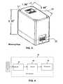
- FIG. 3shows an exemplary embodiment of a bio-reader and its exemplary dimensions, according to one embodiment of the present invention
- FIG. 4depicts an exemplary hardware block diagram of a bio-reader, according to one embodiment of the present invention
- FIG. 5shows an exemplary inner structure of the optical light path of a bio-reader, according to one embodiment of the present invention
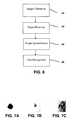
- FIG. 6illustrates an exemplary block diagram of software modules of an exemplary bio-reader, according to one embodiment of the invention
- FIGS. 7A to 7Cshow images of three typical kinds of assays with strong, medium and weak concentrations, respectively;
- FIGS. 8A and 8Bdepict edge detecting masks for detecting a strong target contour, according to one embodiment of the invention.
- FIG. 9depicts a diagram of local area and inner area for medium target detection, according to one embodiment of the present invention.
- FIG. 10shows eight diagrams of partial local area and inner area of an assay according to one embodiment of the present invention.
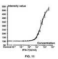
- FIG. 11shows a sample curve depicting a relationship between computed intensity value and real concentration of a target.
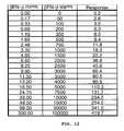
- FIG. 12shows a corresponding data table for the sample curve of FIG. 11 .
- the present inventionis a handheld device as a quantification reader for biological and biochemical detection applications.
- a one-step assaysuch as a lateral flow or capillary assay
- the reporteris reversibly affixed to the solid surface in a region after where detector antibody contacts antigen and a region before where the immobilized capture antibody is located.
- the unknown antigencan be identified, as well as the quantity and concentration of the antigen, which can be quantified, for example, with an optical reader. If the antigen is not present in the sample solution, no “sandwich” complex will be formed, and thus no signal will be observed.
- FIG. 3shows an exemplary embodiment of a bio-reader and its exemplary dimensions. This small size platform allows detection, analysis and quantification of biological data in laboratories and in the field.
- An assay ticket including the targetis inserted in area 32 and a number indicating the concentration of the target is displayed in a display panel 34 .
- the detection targetsinclude, but are not limited to, various cytokines such as Vascular Cell Adhesion Molecule-1 (VCAM-1), Interferon- ⁇ (IFN- ⁇ ), Interleukin-6 (IL-6), and Interleukin-10 (IL-10) in human plasma, blood, urine and other body fluids.
- VCAM-1Vascular Cell Adhesion Molecule-1
- IFN- ⁇Interferon- ⁇
- IL-6Interleukin-6
- IL-10Interleukin-10
- the detection targetsinclude, but are not limited to, various biological agents such as vaccinia, ricin, botulinum toxin and anthrax spores in water.
- FIG. 4depicts an exemplary hardware block diagram of a bio-reader 40 .
- the bio-reader 40includes three main parts: an optical module 42 , a sensor 44 , and a processor 46 .
- the optical module 42is capable of capturing clear and sharp images in the assay tickets.
- the sensor 44for example, a CMOS sensor converts the captured image to digital data to be processed by the processor.
- FIG. 5shows an exemplary inner structure of the optical light path of a bio-reader.
- a light source 52for example, a ring-shape LED light source is applied to provide consistent lighting condition inside the bio-reader.
- a color lightfor example, green is used to obtain the best contrast images of the dyed assay targets.
- a CMOS sensor 54converts the optical image of a ticket 58 to two-dimension digital data with low electric noise and high resolution requirements.
- a processorcontrols the CMOS sensor to capture good quality images of the assay tickets and processes the images to obtain targets' concentrations.
- the processorincludes a Dimensional Digital Signal Processor (D 2 SP), incorporates a two-dimensional image processing engine and supports memory bus interfaces with SDRAM, ROM, flash memory and SRAM devices.
- D 2 SPDimensional Digital Signal Processor
- a 32-bit general purpose I/O portcan be configured to a peripheral bus and an image data port to control digital image sensors.
- FIG. 6illustrates an exemplary block diagram of software modules of an exemplary bio-reader, according to one embodiment of the invention.
- the bio-reader softwareincludes four main modules: an image calibration module 62 , a target detection module 64 , a target quantification module 66 , and a data management module 68 .
- the image calibration module 62extracts a Region of Interest (ROI) covering the target window area from the captured image.
- ROIis the entire ticket window area including a control zone and a target detection zone.
- image calibration module 62computes the brightness and contrast attributions of the captured image based on a control zone area of the ticket image.
- the control zone areaincludes control points or control lines, which are used to check the validity of the testing ticket, that is to indicate whether the ticket is a working (valid) ticket.
- a set of standard ticketsare used for quality control(QC).
- the image attributes of the QC ticketsare set as pre-configured image attributes to check the validity of other testing tickets.
- the image calibration moduleperforms two types of operations for comparing the extracted and the pre-configured image attributes.
- the first operationadjusts the image to meet the required attributes.
- a grayscale compensation for captured imageis conducted based on the difference between the captured image and the pre-configured image attributes. If the first adjustment operation does not meet a given requirement, a second operation is performed to modify the sensor exposure parameters to re-capture the image.
- default sensor exposure parametersinclude a Brightness value of 10, a Contrast value of 11 and an Exposure value of 165.
- the target detection module 64decides a positive (something is detected) or a negative (nothing is detected) result for the target tickets based on the analysis of the captured image. Based on the knowledge of geometrical pattern of the target tickets, the target detection module performs an image enhancement and pattern recognition process.
- the shape pattern of the targetcould be line, circle, rectangle or other geometrical shapes.
- FIGS. 7A to 7Cshow images of three typical kinds of assays with strong, medium and weak concentrations, respectively.
- the image intensitiesvary in large range.
- the background area of the ticket imagemay have some streak noise due to the residual chemical materials, a multi-level detection device is developed for the targets with various intensity and shape features.
- the first level of the detection devicedetects a target with strong concentration. As shown in FIG. 7A , the strong target has very sharp edges. Therefore, an edge detection and circular contour analysis device is applied to extract this kind of target. In one embodiment, the edge detecting masks shown in FIGS. 8A and 8B are applied to detect the strong target contour.
- the gradient magnitude valueis around zero. However for the contour area of the targets with strong concentration, magnitude values are more significant.
- a threshold Th_Ewith a pre-determined value such as 20 is defined. If the magnitude value of an image pixel is larger than the threshold TH_E, this pixel is classified as a point of strong contour point. Otherwise, the pixel is classified as normal background point. If the classified points can generate a circle ring with specified radius, a strong target is detected with the circle's center point as the target's location.
- the second level of the detection devicedetects a target with medium concentration, as shown in FIG. 7B .
- the target area with circular shapeinstead of only strong contour, is separated from background.
- a local area around the targetis selected.
- the local areais a pre-determined area, for example, three times larger than a typical target area.
- the minimal grayscale Min_Grayis found and then the average grayscale AVE_Gray is computed by averaging all of the pixel grayscale values of the local area.
- FIG. 9depicts a diagram of local area and inner area (of the target) for medium target detection, according to one embodiment of the present invention.
- the local areais divided to two areas an inner area and an outer area.
- a pixelbelongs to the inner area of the target, if its distance to the center of the local area is less than N/4. Otherwise, the pixel belongs to the outer area (background).
- An image pointis classified as target point if the grayscale value is less than TH_C. Otherwise, the image point is classified as background point. If the total number of target points within the inner area is larger than N*N/8 and the total number of target points within the outer area is equal to zero, a medium target is detected with the local area's center point as the target's location.
- the third level of the detection devicedetects a weak target.
- the weak targetdoes not have full circular shape.
- the weak targetis extracted based on partial circular shape features extracted from noisy background.
- FIG. 10shows eight diagrams of partial local area and inner area. Similar device for medium target detection is applied on this partial circular shape analysis.
- the local area of interestis half rectangle and inner area is half circular, compared with above-mentioned medium target detection device. As a result, all of the corresponding thresholds are half of the values used for the medium target detection.
- a target quantification module 66computes the image density from the image data and determines the target's concentration by using pre-determined (for example, laboratory developed) data (for example, the curve shown in FIG. 11 )) for specific targets.
- pre-determinedfor example, laboratory developed
- a local area with the located target position as the centeris segmented to perform the image intensity computation (typically, the local area is three times larger than target area).
- the target intensity valueis computed based on the differences of image grayscale values between target area and the background area.
- Ave_All⁇ P ( i,j )/Number_All (3)
- Ave_Tar⁇ P _Tar( i,j )/Number_Tar, P _Tar( i,j ) ⁇ Ave_All (4)
- Ave_Backis the grayscale value of the target point
- Number_Taris the total target point number.
- P_Back(i,j)is the grayscale value of the background point
- Number_Backis the total background point number.
- the target concentrationis obtained from the computed image intensity value using a quantitative pre-determined corresponding curve or a lookup table, stored in a memory of the device or an external computer.
- FIGS. 11 and 12show a sample curve and the corresponding data table to describe the relationship between image intensity value and target concentration for cykotines Interferon- ⁇ (IFN- ⁇ ).
- the curve in FIG. 11shows the corresponding relationship between the target concentration and the computed intensity (Intensity_Value).
- the table in FIG. 12shows some samples. For example, if the computed Intensity_Value is 11.8, then the real target concentration is 750 in unit pg/ml and 2.48 in unit IU/ml.
- the unit IU/mlis defined as Infectious Unit per milliliter, and unit pg is defined as pico gram per milliliter.
- a data management module 68saves the captured image intensity and the computed target concentrations.
- the datacan be uploaded to computers, other handheld devices and the like for further data analysis.
- the bio-reader and the NIDS technologyare utilized to monitor a human immune response by producing an assay capable of detecting Vascular Cell Adhesion Molecule-1 (VCAM-1), Interferon- ⁇ (IFN- ⁇ ), Interleukin-6 (IL-6), and Interleukin-10 (IL-10) in human plasma samples.
- VCAM-1Vascular Cell Adhesion Molecule-1
- IFN- ⁇Interferon- ⁇
- IL-6Interleukin-6
- IL-10Interleukin-10
Landscapes
- Engineering & Computer Science (AREA)
- Health & Medical Sciences (AREA)
- General Health & Medical Sciences (AREA)
- Medical Informatics (AREA)
- Nuclear Medicine, Radiotherapy & Molecular Imaging (AREA)
- Radiology & Medical Imaging (AREA)
- Quality & Reliability (AREA)
- Computer Vision & Pattern Recognition (AREA)
- Physics & Mathematics (AREA)
- General Physics & Mathematics (AREA)
- Theoretical Computer Science (AREA)
- Investigating Or Analysing Materials By Optical Means (AREA)
Abstract
Description
|G|=|Gx|+|Gy| (1)
TH—C=(Min_Gray+AVE_Gray)/2 (2)
Ave_All=ΣP(i,j)/Number_All (3)
Ave_Tar=ΣP_Tar(i,j)/Number_Tar,P_Tar(i,j)<Ave_All (4)
Ave_Back=ΣP_Back(i,j)/Number_Back,P_Back(i,j)>Ave_All (5)
Intensity_Value=(Ave_Tar−Ave_Back)*(Ave_Tar−Ave_Back) (6)
Claims (20)
Priority Applications (2)
| Application Number | Priority Date | Filing Date | Title |
|---|---|---|---|
| US11/501,377US8131477B2 (en) | 2005-11-16 | 2006-08-08 | Method and device for image-based biological data quantification |
| US13/358,244US8583379B2 (en) | 2005-11-16 | 2012-01-25 | Method and device for image-based biological data quantification |
Applications Claiming Priority (2)
| Application Number | Priority Date | Filing Date | Title |
|---|---|---|---|
| US73766505P | 2005-11-16 | 2005-11-16 | |
| US11/501,377US8131477B2 (en) | 2005-11-16 | 2006-08-08 | Method and device for image-based biological data quantification |
Related Child Applications (1)
| Application Number | Title | Priority Date | Filing Date |
|---|---|---|---|
| US13/358,244ContinuationUS8583379B2 (en) | 2005-11-16 | 2012-01-25 | Method and device for image-based biological data quantification |
Publications (2)
| Publication Number | Publication Date |
|---|---|
| US20070112525A1 US20070112525A1 (en) | 2007-05-17 |
| US8131477B2true US8131477B2 (en) | 2012-03-06 |
Family
ID=38041970
Family Applications (2)
| Application Number | Title | Priority Date | Filing Date |
|---|---|---|---|
| US11/501,377Active2030-08-17US8131477B2 (en) | 2005-11-16 | 2006-08-08 | Method and device for image-based biological data quantification |
| US13/358,244ActiveUS8583379B2 (en) | 2005-11-16 | 2012-01-25 | Method and device for image-based biological data quantification |
Family Applications After (1)
| Application Number | Title | Priority Date | Filing Date |
|---|---|---|---|
| US13/358,244ActiveUS8583379B2 (en) | 2005-11-16 | 2012-01-25 | Method and device for image-based biological data quantification |
Country Status (1)
| Country | Link |
|---|---|
| US (2) | US8131477B2 (en) |
Cited By (12)
| Publication number | Priority date | Publication date | Assignee | Title |
|---|---|---|---|---|
| US20080304723A1 (en)* | 2007-06-11 | 2008-12-11 | Ming Hsieh | Bio-reader device with ticket identification |
| US20090268988A1 (en)* | 2002-02-14 | 2009-10-29 | Cogent Systems, Inc. | Method and apparatus for two dimensional image processing |
| US20100027852A1 (en)* | 2004-11-12 | 2010-02-04 | Ming Hsieh | System and Method for Fast Biometric Pattern Matching |
| US8583379B2 (en) | 2005-11-16 | 2013-11-12 | 3M Innovative Properties Company | Method and device for image-based biological data quantification |
| US9547909B2 (en)* | 2014-06-23 | 2017-01-17 | Boe Technology Group Co., Ltd. | Image edge detection method and apparatus thereof, image target identification method and apparatus thereof |
| USD791772S1 (en)* | 2015-05-20 | 2017-07-11 | Chaya Coleena Hendrick | Smart card with a fingerprint sensor |
| US10192144B2 (en) | 2016-04-14 | 2019-01-29 | Research International, Inc. | Coupon reader |
| US10200625B2 (en) | 2014-01-30 | 2019-02-05 | Bd Kiestra B.V. | System and method for image acquisition using supervised high quality imaging |
| US10197558B1 (en) | 2016-09-16 | 2019-02-05 | Cbrn International, Ltd | Environmental sampling and assay device |
| US10318845B2 (en) | 2016-04-14 | 2019-06-11 | Research International, Inc. | Coupon reader |
| US10521910B2 (en) | 2015-04-23 | 2019-12-31 | Bd Kiestra B.V. | Colony contrast gathering |
| US10696938B2 (en) | 2015-04-23 | 2020-06-30 | Bd Kiestra B. V. | Method and system for automated microbial colony counting from streaked sample on plated media |
Families Citing this family (10)
| Publication number | Priority date | Publication date | Assignee | Title |
|---|---|---|---|---|
| US8275179B2 (en)* | 2007-05-01 | 2012-09-25 | 3M Cogent, Inc. | Apparatus for capturing a high quality image of a moist finger |
| US8537237B2 (en)* | 2008-03-12 | 2013-09-17 | Koninklijke Philips N.V. | Real-time digital image processing architecture |
| US20110007178A1 (en)* | 2008-03-12 | 2011-01-13 | Koninklijke Philips Electronics N.V. | Correction of spot area in measuring brightness of sample in biosensing device |
| US20110158489A1 (en)* | 2009-12-31 | 2011-06-30 | Industrial Technology Research Institute | Detection devices and detection method |
| CN102507565B (en)* | 2011-11-30 | 2013-10-16 | 刘江 | Method for searching reaction color development area of immunochromatographic strip |
| US9177223B2 (en) | 2014-01-14 | 2015-11-03 | Welch Allyn, Inc. | Edge detection in images |
| JP7628945B2 (en)* | 2018-07-02 | 2025-02-12 | オルト-クリニカル ダイアグノスティックス インコーポレイテッド | Method and apparatus for selecting a position for reading an image on a slide medium - Patents.com |
| USD962239S1 (en)* | 2020-08-20 | 2022-08-30 | Amazon Technologies, Inc. | Pedestal scanner |
| CN113743249B (en)* | 2021-08-16 | 2024-03-26 | 北京佳服信息科技有限公司 | Method, device and equipment for identifying violations and readable storage medium |
| CN119090871B (en)* | 2024-11-05 | 2025-01-21 | 西安医学院第二附属医院 | Intelligent detection method and system for urine specimen for clinical laboratory |
Citations (80)
| Publication number | Priority date | Publication date | Assignee | Title |
|---|---|---|---|---|
| US4137565A (en) | 1977-01-10 | 1979-01-30 | Xerox Corporation | Direct memory access module for a controller |
| US4315310A (en) | 1979-09-28 | 1982-02-09 | Intel Corporation | Input/output data processing system |
| US4833724A (en) | 1986-08-14 | 1989-05-23 | Amada Engineering & Service Co., Inc. | Imaging device |
| US4924085A (en) | 1988-06-23 | 1990-05-08 | Fujitsu Limited | Uneven-surface data detection apparatus |
| US5233404A (en) | 1989-09-28 | 1993-08-03 | Oscan Electro Optics Inc. | Optical scanning and recording apparatus for fingerprints |
| US5245672A (en) | 1992-03-09 | 1993-09-14 | The United States Of America As Represented By The Secretary Of Commerce | Object/anti-object neural network segmentation |
| US5307345A (en) | 1992-06-25 | 1994-04-26 | Digital Equipment Corporation | Method and apparatus for cut-through data packet transfer in a bridge device |
| US5416573A (en) | 1993-09-10 | 1995-05-16 | Indentix Incorporated | Apparatus for producing fingerprint images which are substantially free of artifacts attributable to moisture on the finger being imaged |
| US5426684A (en) | 1993-11-15 | 1995-06-20 | Eastman Kodak Company | Technique for finding the histogram region of interest for improved tone scale reproduction of digital radiographic images |
| US5517419A (en) | 1993-07-22 | 1996-05-14 | Synectics Corporation | Advanced terrain mapping system |
| US5528355A (en) | 1994-03-11 | 1996-06-18 | Idnetix Incorporated | Electro-optic palm scanner system employing a non-planar platen |
| US5579278A (en) | 1993-11-15 | 1996-11-26 | Micron Technology, Inc. | Multiport memory with pipelined serial input |
| US5596454A (en) | 1994-10-28 | 1997-01-21 | The National Registry, Inc. | Uneven surface image transfer apparatus |
| US5613014A (en) | 1994-10-12 | 1997-03-18 | Martin Marietta Corp. | Fingerprint matching system |
| US5621516A (en) | 1994-02-04 | 1997-04-15 | Fujitsu Limited | Optical device for forming an image of an uneven surface |
| US5633947A (en) | 1991-03-21 | 1997-05-27 | Thorn Emi Plc | Method and apparatus for fingerprint characterization and recognition using auto correlation pattern |
| US5751836A (en) | 1994-09-02 | 1998-05-12 | David Sarnoff Research Center Inc. | Automated, non-invasive iris recognition system and method |
| US5754697A (en) | 1994-12-02 | 1998-05-19 | Fu; Chi-Yung | Selective document image data compression technique |
| US5778175A (en) | 1995-12-22 | 1998-07-07 | Digital Equipment Corporation | Method implemented by a computer network adapter for autonomously adjusting a transmit commencement threshold valve upon concurrence of an underflow condition |
| US5809180A (en) | 1990-01-19 | 1998-09-15 | Fujitsu Limited | Data conversion system for line-narrowing a pattern |
| US5828769A (en) | 1996-10-23 | 1998-10-27 | Autodesk, Inc. | Method and apparatus for recognition of objects via position and orientation consensus of local image encoding |
| US5887079A (en) | 1996-01-31 | 1999-03-23 | Sumitomo Metal Industries Limited | Image processing apparatus |
| US5900993A (en) | 1997-05-09 | 1999-05-04 | Cross Check Corporation | Lens systems for use in fingerprint detection |
| US5937090A (en) | 1996-08-19 | 1999-08-10 | Samsung Electronics Co., Ltd. | Image enhancement method and circuit using quantized mean-matching histogram equalization |
| US5949905A (en) | 1996-10-23 | 1999-09-07 | Nichani; Sanjay | Model-based adaptive segmentation |
| US6002815A (en) | 1997-07-16 | 1999-12-14 | Kinetic Sciences, Inc. | Linear sensor imaging method and apparatus |
| US6038226A (en) | 1997-03-31 | 2000-03-14 | Ericcson Inc. | Combined signalling and PCM cross-connect and packet engine |
| US6043900A (en) | 1998-03-31 | 2000-03-28 | Xerox Corporation | Method and system for automatically detecting a background type of a scanned document utilizing a leadedge histogram thereof |
| US6175407B1 (en) | 1998-12-17 | 2001-01-16 | Identix Incorporated | Apparatus and method for optically imaging features on the surface of a hand |
| WO2001018741A1 (en) | 1999-09-08 | 2001-03-15 | Digital Persona, Inc. | A thin prism fingerprint imager system |
| US6219447B1 (en) | 1997-02-21 | 2001-04-17 | Samsung Electronics Co., Ltd. | Method and circuit for extracting histogram and cumulative distribution function for image enhancement apparatus |
| US6249360B1 (en) | 1997-04-14 | 2001-06-19 | Hewlett-Packard Company | Image scanning device and method |
| US6259108B1 (en) | 1998-10-09 | 2001-07-10 | Kinetic Sciences Inc. | Fingerprint image optical input apparatus |
| US6324020B1 (en) | 1999-08-04 | 2001-11-27 | Secugen Corporation | Method and apparatus for reduction of trapezoidal distortion and improvement of image sharpness in an optical image capturing system |
| US6360307B1 (en) | 1998-06-18 | 2002-03-19 | Cypress Semiconductor Corporation | Circuit architecture and method of writing data to a memory |
| US6384832B1 (en) | 1998-03-05 | 2002-05-07 | Hitachi, Ltd. | Image processing apparatus and image processing system using the apparatus |
| US20020073211A1 (en) | 2000-12-12 | 2002-06-13 | Raymond Lin | System and method for securely communicating between application servers and webservers |
| US6473194B1 (en) | 1998-12-25 | 2002-10-29 | Canon Kabushiki Kaisha | Image processing apparatus and method |
| US6483932B1 (en) | 1999-08-19 | 2002-11-19 | Cross Match Technologies, Inc. | Method and apparatus for rolled fingerprint capture |
| US20030001395A1 (en) | 2001-06-29 | 2003-01-02 | Alcatel | Device for latching and unlatching a removeable cover on a box |
| US6505905B1 (en) | 2001-07-31 | 2003-01-14 | Hewlett-Packard Company | Halftoning method and apparatus |
| US6618076B1 (en) | 1999-12-23 | 2003-09-09 | Justsystem Corporation | Method and apparatus for calibrating projector-camera system |
| US20030185420A1 (en)* | 2002-03-29 | 2003-10-02 | Jason Sefcik | Target detection method and system |
| US6654142B1 (en) | 1998-10-23 | 2003-11-25 | Samsung Electronics Co., Ltd. | Image data processor |
| US6697538B1 (en) | 1999-07-30 | 2004-02-24 | Wisconsin Alumni Research Foundation | Apparatus for producing a flattening map of a digitized image for conformally mapping onto a surface and associated method |
| US20040102931A1 (en) | 2001-02-20 | 2004-05-27 | Ellis Michael D. | Modular personal network systems and methods |
| US20040114829A1 (en) | 2002-10-10 | 2004-06-17 | Intelligent System Solutions Corp. | Method and system for detecting and correcting defects in a digital image |
| US6870538B2 (en) | 1999-11-09 | 2005-03-22 | Broadcom Corporation | Video and graphics system with parallel processing of graphics windows |
| US6879709B2 (en) | 2002-01-17 | 2005-04-12 | International Business Machines Corporation | System and method for automatically detecting neutral expressionless faces in digital images |
| US6912638B2 (en) | 2001-06-28 | 2005-06-28 | Zoran Corporation | System-on-a-chip controller |
| US6928195B2 (en) | 2000-12-18 | 2005-08-09 | Cross Match Technologies, Inc. | Palm scanner using a programmable nutating mirror for increased resolution |
| US6934409B2 (en) | 2000-04-27 | 2005-08-23 | Konica Corporation | PCI radiation image processing apparatus |
| US6956608B1 (en) | 2000-08-11 | 2005-10-18 | Identix Incorporated | Fingerprint imaging device including an optical plate having microreflectors |
| US6980286B1 (en) | 2001-10-25 | 2005-12-27 | Ic Media Corporation | Ultra-thin optical fingerprint sensor with anamorphic optics |
| US20060019265A1 (en)* | 2004-04-30 | 2006-01-26 | Kimberly-Clark Worldwide, Inc. | Transmission-based luminescent detection systems |
| US6993165B2 (en) | 2002-12-06 | 2006-01-31 | Cross Match Technologies, Inc. | System having a rotating optical system and a non-planar prism that are used to obtain print and other hand characteristic information |
| US7020951B2 (en) | 1998-08-21 | 2006-04-04 | International Business Machines | Method of making a merged magnetic read head and write head |
| US7081951B2 (en) | 2003-10-09 | 2006-07-25 | Cross Match Technologies, Inc. | Palm print scanner and methods |
| US7088872B1 (en) | 2002-02-14 | 2006-08-08 | Cogent Systems, Inc. | Method and apparatus for two dimensional image processing |
| US20060224539A1 (en) | 1998-05-01 | 2006-10-05 | Hong Zhang | Computer-aided image analysis |
| US20060245631A1 (en) | 2005-01-27 | 2006-11-02 | Richard Levenson | Classifying image features |
| US7194393B2 (en) | 2001-09-05 | 2007-03-20 | Cogent Systems, Inc. | Numerical model for image feature extraction |
| US7203344B2 (en) | 2002-01-17 | 2007-04-10 | Cross Match Technologies, Inc. | Biometric imaging system and method |
| US20070140550A1 (en) | 2005-12-20 | 2007-06-21 | General Instrument Corporation | Method and apparatus for performing object detection |
| US20070183663A1 (en) | 2006-02-07 | 2007-08-09 | Haohong Wang | Intra-mode region-of-interest video object segmentation |
| US20070189582A1 (en) | 2005-01-26 | 2007-08-16 | Honeywell International Inc. | Approaches and apparatus for eye detection in a digital image |
| US7267799B1 (en)* | 2002-08-14 | 2007-09-11 | Detekt Biomedical, L.L.C. | Universal optical imaging and processing system |
| US7277562B2 (en) | 2003-08-01 | 2007-10-02 | Cross Match Technologies, Inc. | Biometric imaging capture system and method |
| US7315632B2 (en) | 2000-12-22 | 2008-01-01 | Fingerpin Ag | Device for imaging the papillary lines of a finger |
| US20080292194A1 (en) | 2005-04-27 | 2008-11-27 | Mark Schmidt | Method and System for Automatic Detection and Segmentation of Tumors and Associated Edema (Swelling) in Magnetic Resonance (Mri) Images |
| US7564495B2 (en) | 2005-06-14 | 2009-07-21 | Maxemil Photonics Corporation | Thin image-capturing device |
| US7587064B2 (en) | 2004-02-03 | 2009-09-08 | Hrl Laboratories, Llc | Active learning system for object fingerprinting |
| US7616788B2 (en) | 2004-11-12 | 2009-11-10 | Cogent Systems, Inc. | System and method for fast biometric pattern matching |
| US7639858B2 (en) | 2003-06-06 | 2009-12-29 | Ncr Corporation | Currency validation |
| US20100049674A1 (en) | 2005-04-17 | 2010-02-25 | Rafael - Armament Development Authority Ltd. | Generic classification system |
| US7796266B2 (en) | 2004-04-30 | 2010-09-14 | Kimberly-Clark Worldwide, Inc. | Optical detection system using electromagnetic radiation to detect presence or quantity of analyte |
| US7840062B2 (en) | 2004-11-19 | 2010-11-23 | Koninklijke Philips Electronics, N.V. | False positive reduction in computer-assisted detection (CAD) with new 3D features |
| US20100304358A1 (en) | 2005-08-15 | 2010-12-02 | Shuming Nie | Methods of identifying biological targets and instrumentation to identify biological targets |
| US7876934B2 (en) | 2004-11-08 | 2011-01-25 | Siemens Medical Solutions Usa, Inc. | Method of database-guided segmentation of anatomical structures having complex appearances |
| US7912528B2 (en) | 2003-06-25 | 2011-03-22 | Siemens Medical Solutions Usa, Inc. | Systems and methods for automated diagnosis and decision support for heart related diseases and conditions |
Family Cites Families (35)
| Publication number | Priority date | Publication date | Assignee | Title |
|---|---|---|---|---|
| CA1187997A (en) | 1982-07-09 | 1985-05-28 | Inc. Fingermatrix | Fingerprint image refinement |
| US4569080A (en) | 1982-07-09 | 1986-02-04 | Fingermatrix, Inc. | Fingerprint image refinement |
| US4832485A (en) | 1982-09-03 | 1989-05-23 | Commonwealth Technology, Inc. | Image enhancer |
| US4574393A (en)* | 1983-04-14 | 1986-03-04 | Blackwell George F | Gray scale image processor |
| DK155242C (en) | 1985-05-02 | 1989-07-31 | Jydsk Telefon As | METHOD AND APPARATUS FOR AUTOMATIC DETECTION OF FINGERPRINT |
| US5619586A (en) | 1990-12-20 | 1997-04-08 | Thorn Emi Plc | Method and apparatus for producing a directly viewable image of a fingerprint |
| US5448649A (en) | 1994-05-24 | 1995-09-05 | Chen; Wang S. | Apparatus for imaging fingerprint or topographic relief pattern on the surface of an object |
| US5659626A (en) | 1994-10-20 | 1997-08-19 | Calspan Corporation | Fingerprint identification system |
| US5956307A (en) | 1995-03-08 | 1999-09-21 | Matsushita Electric Industrial Co., Ltd. | Device end method for reproducing data from disk, method for controlling rotation of disk, and reproduction clock generating device |
| US5942761A (en) | 1995-06-07 | 1999-08-24 | Tuli; Raja Singh | Enhancement methods and devices for reading a fingerprint image |
| JPH10289304A (en) | 1997-02-12 | 1998-10-27 | Nec Corp | Fingerprint image input device |
| US6317810B1 (en) | 1997-06-25 | 2001-11-13 | Sun Microsystems, Inc. | Microprocessor having a prefetch cache |
| US5996061A (en) | 1997-06-25 | 1999-11-30 | Sun Microsystems, Inc. | Method for invalidating data identified by software compiler |
| US6138212A (en) | 1997-06-25 | 2000-10-24 | Sun Microsystems, Inc. | Apparatus and method for generating a stride used to derive a prefetch address |
| AU2001291175A1 (en) | 2000-09-21 | 2002-04-02 | Md Online Inc. | Medical image processing systems |
| DK1432786T3 (en)* | 2001-09-06 | 2009-10-26 | Rapid Micro Biosystems Inc | Rapid detection of replicated cells |
| US7418123B2 (en) | 2002-07-12 | 2008-08-26 | University Of Chicago | Automated method and system for computerized image analysis for prognosis |
| US20040086890A1 (en) | 2002-10-25 | 2004-05-06 | Stratagene | DNA polymerases with reduced base analog detection activity |
| KR100486735B1 (en) | 2003-02-28 | 2005-05-03 | 삼성전자주식회사 | Method of establishing optimum-partitioned classifed neural network and apparatus and method and apparatus for automatic labeling using optimum-partitioned classifed neural network |
| US8131477B2 (en) | 2005-11-16 | 2012-03-06 | 3M Cogent, Inc. | Method and device for image-based biological data quantification |
| KR100771244B1 (en) | 2006-06-12 | 2007-10-29 | 삼성전자주식회사 | Video data processing method and device |
| US8073253B2 (en) | 2006-09-29 | 2011-12-06 | General Electric Company | Machine learning based triple region segmentation framework using level set on PACS |
| US8503796B2 (en) | 2006-12-29 | 2013-08-06 | Ncr Corporation | Method of validating a media item |
| US8611665B2 (en) | 2006-12-29 | 2013-12-17 | Ncr Corporation | Method of recognizing a media item |
| US20080170778A1 (en) | 2007-01-15 | 2008-07-17 | Huitao Luo | Method and system for detection and removal of redeyes |
| US8175350B2 (en) | 2007-01-15 | 2012-05-08 | Eigen, Inc. | Method for tissue culture extraction |
| US8275179B2 (en) | 2007-05-01 | 2012-09-25 | 3M Cogent, Inc. | Apparatus for capturing a high quality image of a moist finger |
| US8014603B2 (en) | 2007-08-30 | 2011-09-06 | Xerox Corporation | System and method for characterizing handwritten or typed words in a document |
| US8170330B2 (en) | 2007-10-30 | 2012-05-01 | Siemens Aktiengesellschaft | Machine learning for tissue labeling segmentation |
| US8139831B2 (en) | 2007-12-06 | 2012-03-20 | Siemens Aktiengesellschaft | System and method for unsupervised detection and gleason grading of prostate cancer whole mounts using NIR fluorscence |
| US20090154814A1 (en) | 2007-12-12 | 2009-06-18 | Natan Y Aakov Ben | Classifying objects using partitions and machine vision techniques |
| US7938785B2 (en) | 2007-12-27 | 2011-05-10 | Teledyne Scientific & Imaging, Llc | Fusion-based spatio-temporal feature detection for robust classification of instantaneous changes in pupil response as a correlate of cognitive response |
| US20090185746A1 (en) | 2008-01-22 | 2009-07-23 | The University Of Western Australia | Image recognition |
| US8331666B2 (en) | 2008-03-03 | 2012-12-11 | Csr Technology Inc. | Automatic red eye artifact reduction for images |
| US8213725B2 (en) | 2009-03-20 | 2012-07-03 | Eastman Kodak Company | Semantic event detection using cross-domain knowledge |
- 2006
- 2006-08-08USUS11/501,377patent/US8131477B2/enactiveActive
- 2012
- 2012-01-25USUS13/358,244patent/US8583379B2/enactiveActive
Patent Citations (86)
| Publication number | Priority date | Publication date | Assignee | Title |
|---|---|---|---|---|
| US4137565A (en) | 1977-01-10 | 1979-01-30 | Xerox Corporation | Direct memory access module for a controller |
| US4315310A (en) | 1979-09-28 | 1982-02-09 | Intel Corporation | Input/output data processing system |
| US4833724A (en) | 1986-08-14 | 1989-05-23 | Amada Engineering & Service Co., Inc. | Imaging device |
| US4924085A (en) | 1988-06-23 | 1990-05-08 | Fujitsu Limited | Uneven-surface data detection apparatus |
| US5233404A (en) | 1989-09-28 | 1993-08-03 | Oscan Electro Optics Inc. | Optical scanning and recording apparatus for fingerprints |
| US5809180A (en) | 1990-01-19 | 1998-09-15 | Fujitsu Limited | Data conversion system for line-narrowing a pattern |
| US5633947A (en) | 1991-03-21 | 1997-05-27 | Thorn Emi Plc | Method and apparatus for fingerprint characterization and recognition using auto correlation pattern |
| US5245672A (en) | 1992-03-09 | 1993-09-14 | The United States Of America As Represented By The Secretary Of Commerce | Object/anti-object neural network segmentation |
| US5307345A (en) | 1992-06-25 | 1994-04-26 | Digital Equipment Corporation | Method and apparatus for cut-through data packet transfer in a bridge device |
| US5517419A (en) | 1993-07-22 | 1996-05-14 | Synectics Corporation | Advanced terrain mapping system |
| US5416573A (en) | 1993-09-10 | 1995-05-16 | Indentix Incorporated | Apparatus for producing fingerprint images which are substantially free of artifacts attributable to moisture on the finger being imaged |
| US5426684A (en) | 1993-11-15 | 1995-06-20 | Eastman Kodak Company | Technique for finding the histogram region of interest for improved tone scale reproduction of digital radiographic images |
| US5579278A (en) | 1993-11-15 | 1996-11-26 | Micron Technology, Inc. | Multiport memory with pipelined serial input |
| US5621516A (en) | 1994-02-04 | 1997-04-15 | Fujitsu Limited | Optical device for forming an image of an uneven surface |
| US5528355A (en) | 1994-03-11 | 1996-06-18 | Idnetix Incorporated | Electro-optic palm scanner system employing a non-planar platen |
| US5751836A (en) | 1994-09-02 | 1998-05-12 | David Sarnoff Research Center Inc. | Automated, non-invasive iris recognition system and method |
| US5613014A (en) | 1994-10-12 | 1997-03-18 | Martin Marietta Corp. | Fingerprint matching system |
| US5596454A (en) | 1994-10-28 | 1997-01-21 | The National Registry, Inc. | Uneven surface image transfer apparatus |
| US5754697A (en) | 1994-12-02 | 1998-05-19 | Fu; Chi-Yung | Selective document image data compression technique |
| US5778175A (en) | 1995-12-22 | 1998-07-07 | Digital Equipment Corporation | Method implemented by a computer network adapter for autonomously adjusting a transmit commencement threshold valve upon concurrence of an underflow condition |
| US5887079A (en) | 1996-01-31 | 1999-03-23 | Sumitomo Metal Industries Limited | Image processing apparatus |
| US5937090A (en) | 1996-08-19 | 1999-08-10 | Samsung Electronics Co., Ltd. | Image enhancement method and circuit using quantized mean-matching histogram equalization |
| US5949905A (en) | 1996-10-23 | 1999-09-07 | Nichani; Sanjay | Model-based adaptive segmentation |
| US5828769A (en) | 1996-10-23 | 1998-10-27 | Autodesk, Inc. | Method and apparatus for recognition of objects via position and orientation consensus of local image encoding |
| US6219447B1 (en) | 1997-02-21 | 2001-04-17 | Samsung Electronics Co., Ltd. | Method and circuit for extracting histogram and cumulative distribution function for image enhancement apparatus |
| US6038226A (en) | 1997-03-31 | 2000-03-14 | Ericcson Inc. | Combined signalling and PCM cross-connect and packet engine |
| US6249360B1 (en) | 1997-04-14 | 2001-06-19 | Hewlett-Packard Company | Image scanning device and method |
| US5900993A (en) | 1997-05-09 | 1999-05-04 | Cross Check Corporation | Lens systems for use in fingerprint detection |
| US6002815A (en) | 1997-07-16 | 1999-12-14 | Kinetic Sciences, Inc. | Linear sensor imaging method and apparatus |
| US6384832B1 (en) | 1998-03-05 | 2002-05-07 | Hitachi, Ltd. | Image processing apparatus and image processing system using the apparatus |
| US6043900A (en) | 1998-03-31 | 2000-03-28 | Xerox Corporation | Method and system for automatically detecting a background type of a scanned document utilizing a leadedge histogram thereof |
| US20060224539A1 (en) | 1998-05-01 | 2006-10-05 | Hong Zhang | Computer-aided image analysis |
| US6360307B1 (en) | 1998-06-18 | 2002-03-19 | Cypress Semiconductor Corporation | Circuit architecture and method of writing data to a memory |
| US7020951B2 (en) | 1998-08-21 | 2006-04-04 | International Business Machines | Method of making a merged magnetic read head and write head |
| US6355937B2 (en) | 1998-10-09 | 2002-03-12 | Kinetic Sciences Inc. | Fingerprint image optical input apparatus |
| US6259108B1 (en) | 1998-10-09 | 2001-07-10 | Kinetic Sciences Inc. | Fingerprint image optical input apparatus |
| US6654142B1 (en) | 1998-10-23 | 2003-11-25 | Samsung Electronics Co., Ltd. | Image data processor |
| US6175407B1 (en) | 1998-12-17 | 2001-01-16 | Identix Incorporated | Apparatus and method for optically imaging features on the surface of a hand |
| US6473194B1 (en) | 1998-12-25 | 2002-10-29 | Canon Kabushiki Kaisha | Image processing apparatus and method |
| US6697538B1 (en) | 1999-07-30 | 2004-02-24 | Wisconsin Alumni Research Foundation | Apparatus for producing a flattening map of a digitized image for conformally mapping onto a surface and associated method |
| US6324020B1 (en) | 1999-08-04 | 2001-11-27 | Secugen Corporation | Method and apparatus for reduction of trapezoidal distortion and improvement of image sharpness in an optical image capturing system |
| US7095880B2 (en) | 1999-08-19 | 2006-08-22 | Cross Match Technologies, Inc. | Method and apparatus for rolled fingerprint capture |
| US6483932B1 (en) | 1999-08-19 | 2002-11-19 | Cross Match Technologies, Inc. | Method and apparatus for rolled fingerprint capture |
| WO2001018741A1 (en) | 1999-09-08 | 2001-03-15 | Digital Persona, Inc. | A thin prism fingerprint imager system |
| US6870538B2 (en) | 1999-11-09 | 2005-03-22 | Broadcom Corporation | Video and graphics system with parallel processing of graphics windows |
| US6618076B1 (en) | 1999-12-23 | 2003-09-09 | Justsystem Corporation | Method and apparatus for calibrating projector-camera system |
| US6934409B2 (en) | 2000-04-27 | 2005-08-23 | Konica Corporation | PCI radiation image processing apparatus |
| US6956608B1 (en) | 2000-08-11 | 2005-10-18 | Identix Incorporated | Fingerprint imaging device including an optical plate having microreflectors |
| US20020073211A1 (en) | 2000-12-12 | 2002-06-13 | Raymond Lin | System and method for securely communicating between application servers and webservers |
| US6928195B2 (en) | 2000-12-18 | 2005-08-09 | Cross Match Technologies, Inc. | Palm scanner using a programmable nutating mirror for increased resolution |
| US7315632B2 (en) | 2000-12-22 | 2008-01-01 | Fingerpin Ag | Device for imaging the papillary lines of a finger |
| US20040102931A1 (en) | 2001-02-20 | 2004-05-27 | Ellis Michael D. | Modular personal network systems and methods |
| US6912638B2 (en) | 2001-06-28 | 2005-06-28 | Zoran Corporation | System-on-a-chip controller |
| US20030001395A1 (en) | 2001-06-29 | 2003-01-02 | Alcatel | Device for latching and unlatching a removeable cover on a box |
| US6505905B1 (en) | 2001-07-31 | 2003-01-14 | Hewlett-Packard Company | Halftoning method and apparatus |
| US7194393B2 (en) | 2001-09-05 | 2007-03-20 | Cogent Systems, Inc. | Numerical model for image feature extraction |
| US6980286B1 (en) | 2001-10-25 | 2005-12-27 | Ic Media Corporation | Ultra-thin optical fingerprint sensor with anamorphic optics |
| US6879709B2 (en) | 2002-01-17 | 2005-04-12 | International Business Machines Corporation | System and method for automatically detecting neutral expressionless faces in digital images |
| US7203344B2 (en) | 2002-01-17 | 2007-04-10 | Cross Match Technologies, Inc. | Biometric imaging system and method |
| US20090268988A1 (en) | 2002-02-14 | 2009-10-29 | Cogent Systems, Inc. | Method and apparatus for two dimensional image processing |
| US7088872B1 (en) | 2002-02-14 | 2006-08-08 | Cogent Systems, Inc. | Method and apparatus for two dimensional image processing |
| US7580567B2 (en) | 2002-02-14 | 2009-08-25 | Cogent Systems, Inc. | Method and apparatus for two dimensional image processing |
| US7430303B2 (en) | 2002-03-29 | 2008-09-30 | Lockheed Martin Corporation | Target detection method and system |
| US20030185420A1 (en)* | 2002-03-29 | 2003-10-02 | Jason Sefcik | Target detection method and system |
| US7267799B1 (en)* | 2002-08-14 | 2007-09-11 | Detekt Biomedical, L.L.C. | Universal optical imaging and processing system |
| US20040114829A1 (en) | 2002-10-10 | 2004-06-17 | Intelligent System Solutions Corp. | Method and system for detecting and correcting defects in a digital image |
| US6993165B2 (en) | 2002-12-06 | 2006-01-31 | Cross Match Technologies, Inc. | System having a rotating optical system and a non-planar prism that are used to obtain print and other hand characteristic information |
| US7639858B2 (en) | 2003-06-06 | 2009-12-29 | Ncr Corporation | Currency validation |
| US7912528B2 (en) | 2003-06-25 | 2011-03-22 | Siemens Medical Solutions Usa, Inc. | Systems and methods for automated diagnosis and decision support for heart related diseases and conditions |
| US7277562B2 (en) | 2003-08-01 | 2007-10-02 | Cross Match Technologies, Inc. | Biometric imaging capture system and method |
| US7081951B2 (en) | 2003-10-09 | 2006-07-25 | Cross Match Technologies, Inc. | Palm print scanner and methods |
| US7587064B2 (en) | 2004-02-03 | 2009-09-08 | Hrl Laboratories, Llc | Active learning system for object fingerprinting |
| US7796266B2 (en) | 2004-04-30 | 2010-09-14 | Kimberly-Clark Worldwide, Inc. | Optical detection system using electromagnetic radiation to detect presence or quantity of analyte |
| US20060019265A1 (en)* | 2004-04-30 | 2006-01-26 | Kimberly-Clark Worldwide, Inc. | Transmission-based luminescent detection systems |
| US7876934B2 (en) | 2004-11-08 | 2011-01-25 | Siemens Medical Solutions Usa, Inc. | Method of database-guided segmentation of anatomical structures having complex appearances |
| US20100027852A1 (en) | 2004-11-12 | 2010-02-04 | Ming Hsieh | System and Method for Fast Biometric Pattern Matching |
| US7616788B2 (en) | 2004-11-12 | 2009-11-10 | Cogent Systems, Inc. | System and method for fast biometric pattern matching |
| US7840062B2 (en) | 2004-11-19 | 2010-11-23 | Koninklijke Philips Electronics, N.V. | False positive reduction in computer-assisted detection (CAD) with new 3D features |
| US20070189582A1 (en) | 2005-01-26 | 2007-08-16 | Honeywell International Inc. | Approaches and apparatus for eye detection in a digital image |
| US20060245631A1 (en) | 2005-01-27 | 2006-11-02 | Richard Levenson | Classifying image features |
| US20100049674A1 (en) | 2005-04-17 | 2010-02-25 | Rafael - Armament Development Authority Ltd. | Generic classification system |
| US20080292194A1 (en) | 2005-04-27 | 2008-11-27 | Mark Schmidt | Method and System for Automatic Detection and Segmentation of Tumors and Associated Edema (Swelling) in Magnetic Resonance (Mri) Images |
| US7564495B2 (en) | 2005-06-14 | 2009-07-21 | Maxemil Photonics Corporation | Thin image-capturing device |
| US20100304358A1 (en) | 2005-08-15 | 2010-12-02 | Shuming Nie | Methods of identifying biological targets and instrumentation to identify biological targets |
| US20070140550A1 (en) | 2005-12-20 | 2007-06-21 | General Instrument Corporation | Method and apparatus for performing object detection |
| US20070183663A1 (en) | 2006-02-07 | 2007-08-09 | Haohong Wang | Intra-mode region-of-interest video object segmentation |
Non-Patent Citations (8)
| Title |
|---|
| Carlson et al. Biosensors and Bioelectronics (2000) vol. 14, pp. 841-848.* |
| Delmulle et al. J. Agric. Food Chem. (2005) vol. 53, pp. 3364-3368.* |
| Muhammad-Tahir Biosensor and Bioelectronics (2003) vol. 18, pp. 813-819.* |
| Neidbala et al. (Anal. Biochem. (2001) vol. 293, pp. 22-30).* |
| Seul et al. (Practical Algorithms for Image Analysis (2000), Chapter 1, Introduction, Cambridge University Press, pp. 1-22).* |
| Seul et al. (Practical Algorithms for Image Analysis (2000), Chapter 1, Introduction, Cambridge University Press; Chapter 2, pp. 21-24 and 27-28; Chapter 3, pp. 56-95; Chapter 4, pp. 132-150; Chapter 7, pp. 248-264).* |
| U.S. Appl. No. 60/357,557, entitled "Hardware Architecture for Two Dimensional Digital Image Processing," filed Feb. 14, 2002. |
| Vincent et al. IEEE Transactions on Image Processing (1993) vol. 2, No. 2, pp. 176-201.* |
Cited By (21)
| Publication number | Priority date | Publication date | Assignee | Title |
|---|---|---|---|---|
| US20090268988A1 (en)* | 2002-02-14 | 2009-10-29 | Cogent Systems, Inc. | Method and apparatus for two dimensional image processing |
| US8254728B2 (en) | 2002-02-14 | 2012-08-28 | 3M Cogent, Inc. | Method and apparatus for two dimensional image processing |
| US20100027852A1 (en)* | 2004-11-12 | 2010-02-04 | Ming Hsieh | System and Method for Fast Biometric Pattern Matching |
| US8379982B2 (en) | 2004-11-12 | 2013-02-19 | 3M Cogent, Inc. | System and method for fast biometric pattern matching |
| US8583379B2 (en) | 2005-11-16 | 2013-11-12 | 3M Innovative Properties Company | Method and device for image-based biological data quantification |
| US20080304723A1 (en)* | 2007-06-11 | 2008-12-11 | Ming Hsieh | Bio-reader device with ticket identification |
| US8411916B2 (en)* | 2007-06-11 | 2013-04-02 | 3M Cogent, Inc. | Bio-reader device with ticket identification |
| US10200625B2 (en) | 2014-01-30 | 2019-02-05 | Bd Kiestra B.V. | System and method for image acquisition using supervised high quality imaging |
| US10841503B2 (en) | 2014-01-30 | 2020-11-17 | Bd Kiestra B.V. | System and method for image acquisition using supervised high quality imaging |
| US9547909B2 (en)* | 2014-06-23 | 2017-01-17 | Boe Technology Group Co., Ltd. | Image edge detection method and apparatus thereof, image target identification method and apparatus thereof |
| US11674116B2 (en) | 2015-04-23 | 2023-06-13 | Bd Kiestra B.V. | Method and system for automated microbial colony counting from streaked sample on plated media |
| US10521910B2 (en) | 2015-04-23 | 2019-12-31 | Bd Kiestra B.V. | Colony contrast gathering |
| US12331277B2 (en) | 2015-04-23 | 2025-06-17 | Bd Kiestra B.V. | Method and system for automated microbial colony counting from streaked sample on plated media |
| US10696938B2 (en) | 2015-04-23 | 2020-06-30 | Bd Kiestra B. V. | Method and system for automated microbial colony counting from streaked sample on plated media |
| USD791772S1 (en)* | 2015-05-20 | 2017-07-11 | Chaya Coleena Hendrick | Smart card with a fingerprint sensor |
| US10192144B2 (en) | 2016-04-14 | 2019-01-29 | Research International, Inc. | Coupon reader |
| US10318845B2 (en) | 2016-04-14 | 2019-06-11 | Research International, Inc. | Coupon reader |
| US11023773B2 (en) | 2016-04-14 | 2021-06-01 | Research International, Inc. | Coupon reader |
| US10197558B1 (en) | 2016-09-16 | 2019-02-05 | Cbrn International, Ltd | Environmental sampling and assay device |
| US11543405B2 (en) | 2016-09-16 | 2023-01-03 | Cbrn International, Ltd. | Environmental sampling and assay device |
| US10690660B2 (en) | 2016-09-16 | 2020-06-23 | Cbrn International, Ltd. | Environmental sampling and assay device |
Also Published As
| Publication number | Publication date |
|---|---|
| US20070112525A1 (en) | 2007-05-17 |
| US8583379B2 (en) | 2013-11-12 |
| US20120120233A1 (en) | 2012-05-17 |
Similar Documents
| Publication | Publication Date | Title |
|---|---|---|
| US8131477B2 (en) | Method and device for image-based biological data quantification | |
| US12352747B2 (en) | System for analyzing quantitative lateral flow chromatography | |
| US11674883B2 (en) | Image-based assay performance improvement | |
| US20230324278A1 (en) | Assay accuracy improvement | |
| EP2281197B1 (en) | Method of detecting very low levels of analyte within a thin film fluid sample contained in a thin thickness chamber | |
| EP4083852A1 (en) | Virus detection and quantification method in fluid samples by digital processing diffuse optical reflectance hyperspectral images obtained in the visible and near infrared ranges | |
| CN111812013B (en) | Method for optically detecting biomarkers | |
| CN110573859A (en) | Method and apparatus for HILN characterization using convolutional neural networks | |
| US8417002B2 (en) | Method for analyzing image data relating to agglutination assays | |
| CN112070711A (en) | A method for analyzing microdroplets in a microdroplet image detection method | |
| US11609233B2 (en) | Indicator-based analysis of a sample | |
| Zheng et al. | Simultaneous quantitative detection of Helicobacter pylori based on a rapid and sensitive testing platform using quantum dots-labeled immunochromatiographic test strips | |
| Jing et al. | A novel method for quantitative analysis of C-reactive protein lateral flow immunoassays images via CMOS sensor and recurrent neural networks | |
| Sivakumar et al. | An automated lateral flow assay identification framework: Exploring the challenges of a wearable lateral flow assay in mobile application | |
| US5541417A (en) | Quantative agglutination reaction analysis method | |
| EP2181334B1 (en) | Read-out method and apparatus | |
| US8411916B2 (en) | Bio-reader device with ticket identification | |
| KR102629904B1 (en) | Method and apparatus for correcting position and color of diagnostic kit image using machine learning and image processing | |
| JP2020509347A (en) | Cell analysis method and device | |
| CN120009532B (en) | Immunochromatography detection method and system for clinical laboratory | |
| Hergenröder et al. | 2.2 Virus Detection | |
| Waranusast et al. | The Development of Mobile Application for Assisting COVID-19 Antigen Test Kit Results Reading | |
| Sivakumar et al. | A Novel Lateral Flow Immunoassay Identification Framework that Tackles the Challenges of Colorimetric Readout | |
| KR20250125399A (en) | An improved method for performing fluorescence measurements of samples | |
| Shuo et al. | Quantitative analytical colloidal gold instrument using android smart phone |
Legal Events
| Date | Code | Title | Description |
|---|---|---|---|
| AS | Assignment | Owner name:COGENT, INC.,CALIFORNIA Free format text:ASSIGNMENT OF ASSIGNORS INTEREST;ASSIGNORS:LI, SONGTAO;HSIEH, MING;TANG, XIAN;AND OTHERS;SIGNING DATES FROM 20060720 TO 20060721;REEL/FRAME:018174/0639 Owner name:COGENT, INC., CALIFORNIA Free format text:ASSIGNMENT OF ASSIGNORS INTEREST;ASSIGNORS:LI, SONGTAO;HSIEH, MING;TANG, XIAN;AND OTHERS;SIGNING DATES FROM 20060720 TO 20060721;REEL/FRAME:018174/0639 | |
| AS | Assignment | Owner name:3M COGENT, INC., CALIFORNIA Free format text:MERGER AND CHANGE OF NAME;ASSIGNOR:COGENT, INC.;REEL/FRAME:026375/0875 Effective date:20101201 | |
| STCF | Information on status: patent grant | Free format text:PATENTED CASE | |
| CC | Certificate of correction | ||
| FPAY | Fee payment | Year of fee payment:4 | |
| AS | Assignment | Owner name:GEMALTO SA, FRANCE Free format text:ASSIGNMENT OF ASSIGNORS INTEREST;ASSIGNOR:3M COGENT, INC.;REEL/FRAME:042962/0397 Effective date:20170501 | |
| MAFP | Maintenance fee payment | Free format text:PAYMENT OF MAINTENANCE FEE, 8TH YEAR, LARGE ENTITY (ORIGINAL EVENT CODE: M1552); ENTITY STATUS OF PATENT OWNER: LARGE ENTITY Year of fee payment:8 | |
| MAFP | Maintenance fee payment | Free format text:PAYMENT OF MAINTENANCE FEE, 12TH YEAR, LARGE ENTITY (ORIGINAL EVENT CODE: M1553); ENTITY STATUS OF PATENT OWNER: LARGE ENTITY Year of fee payment:12 | |
| AS | Assignment | Owner name:THALES DIS FRANCE SA, FRANCE Free format text:CHANGE OF NAME;ASSIGNOR:GEMALTO SA;REEL/FRAME:064792/0374 Effective date:20190716 | |
| AS | Assignment | Owner name:THALES DIS FRANCE SAS, FRANCE Free format text:ASSIGNMENT OF ASSIGNORS INTEREST;ASSIGNOR:THALES DIS FRANCE SA;REEL/FRAME:064870/0162 Effective date:20211215 |