US8131437B2 - Method for operating a powertrain system to transition between engine states - Google Patents
Method for operating a powertrain system to transition between engine statesDownload PDFInfo
- Publication number
- US8131437B2 US8131437B2US12/253,988US25398808AUS8131437B2US 8131437 B2US8131437 B2US 8131437B2US 25398808 AUS25398808 AUS 25398808AUS 8131437 B2US8131437 B2US 8131437B2
- Authority
- US
- United States
- Prior art keywords
- engine
- state
- torque
- preferred
- cylinder
- Prior art date
- Legal status (The legal status is an assumption and is not a legal conclusion. Google has not performed a legal analysis and makes no representation as to the accuracy of the status listed.)
- Active, expires
Links
Images


Classifications
- B—PERFORMING OPERATIONS; TRANSPORTING
- B60—VEHICLES IN GENERAL
- B60K—ARRANGEMENT OR MOUNTING OF PROPULSION UNITS OR OF TRANSMISSIONS IN VEHICLES; ARRANGEMENT OR MOUNTING OF PLURAL DIVERSE PRIME-MOVERS IN VEHICLES; AUXILIARY DRIVES FOR VEHICLES; INSTRUMENTATION OR DASHBOARDS FOR VEHICLES; ARRANGEMENTS IN CONNECTION WITH COOLING, AIR INTAKE, GAS EXHAUST OR FUEL SUPPLY OF PROPULSION UNITS IN VEHICLES
- B60K6/00—Arrangement or mounting of plural diverse prime-movers for mutual or common propulsion, e.g. hybrid propulsion systems comprising electric motors and internal combustion engines
- B60K6/20—Arrangement or mounting of plural diverse prime-movers for mutual or common propulsion, e.g. hybrid propulsion systems comprising electric motors and internal combustion engines the prime-movers consisting of electric motors and internal combustion engines, e.g. HEVs
- B60K6/22—Arrangement or mounting of plural diverse prime-movers for mutual or common propulsion, e.g. hybrid propulsion systems comprising electric motors and internal combustion engines the prime-movers consisting of electric motors and internal combustion engines, e.g. HEVs characterised by apparatus, components or means specially adapted for HEVs
- B60K6/26—Arrangement or mounting of plural diverse prime-movers for mutual or common propulsion, e.g. hybrid propulsion systems comprising electric motors and internal combustion engines the prime-movers consisting of electric motors and internal combustion engines, e.g. HEVs characterised by apparatus, components or means specially adapted for HEVs characterised by the motors or the generators
- B—PERFORMING OPERATIONS; TRANSPORTING
- B60—VEHICLES IN GENERAL
- B60W—CONJOINT CONTROL OF VEHICLE SUB-UNITS OF DIFFERENT TYPE OR DIFFERENT FUNCTION; CONTROL SYSTEMS SPECIALLY ADAPTED FOR HYBRID VEHICLES; ROAD VEHICLE DRIVE CONTROL SYSTEMS FOR PURPOSES NOT RELATED TO THE CONTROL OF A PARTICULAR SUB-UNIT
- B60W20/00—Control systems specially adapted for hybrid vehicles
- B60W20/10—Controlling the power contribution of each of the prime movers to meet required power demand
- B—PERFORMING OPERATIONS; TRANSPORTING
- B60—VEHICLES IN GENERAL
- B60K—ARRANGEMENT OR MOUNTING OF PROPULSION UNITS OR OF TRANSMISSIONS IN VEHICLES; ARRANGEMENT OR MOUNTING OF PLURAL DIVERSE PRIME-MOVERS IN VEHICLES; AUXILIARY DRIVES FOR VEHICLES; INSTRUMENTATION OR DASHBOARDS FOR VEHICLES; ARRANGEMENTS IN CONNECTION WITH COOLING, AIR INTAKE, GAS EXHAUST OR FUEL SUPPLY OF PROPULSION UNITS IN VEHICLES
- B60K6/00—Arrangement or mounting of plural diverse prime-movers for mutual or common propulsion, e.g. hybrid propulsion systems comprising electric motors and internal combustion engines
- B60K6/20—Arrangement or mounting of plural diverse prime-movers for mutual or common propulsion, e.g. hybrid propulsion systems comprising electric motors and internal combustion engines the prime-movers consisting of electric motors and internal combustion engines, e.g. HEVs
- B60K6/22—Arrangement or mounting of plural diverse prime-movers for mutual or common propulsion, e.g. hybrid propulsion systems comprising electric motors and internal combustion engines the prime-movers consisting of electric motors and internal combustion engines, e.g. HEVs characterised by apparatus, components or means specially adapted for HEVs
- B60K6/36—Arrangement or mounting of plural diverse prime-movers for mutual or common propulsion, e.g. hybrid propulsion systems comprising electric motors and internal combustion engines the prime-movers consisting of electric motors and internal combustion engines, e.g. HEVs characterised by apparatus, components or means specially adapted for HEVs characterised by the transmission gearings
- B60K6/365—Arrangement or mounting of plural diverse prime-movers for mutual or common propulsion, e.g. hybrid propulsion systems comprising electric motors and internal combustion engines the prime-movers consisting of electric motors and internal combustion engines, e.g. HEVs characterised by apparatus, components or means specially adapted for HEVs characterised by the transmission gearings with the gears having orbital motion
- B—PERFORMING OPERATIONS; TRANSPORTING
- B60—VEHICLES IN GENERAL
- B60K—ARRANGEMENT OR MOUNTING OF PROPULSION UNITS OR OF TRANSMISSIONS IN VEHICLES; ARRANGEMENT OR MOUNTING OF PLURAL DIVERSE PRIME-MOVERS IN VEHICLES; AUXILIARY DRIVES FOR VEHICLES; INSTRUMENTATION OR DASHBOARDS FOR VEHICLES; ARRANGEMENTS IN CONNECTION WITH COOLING, AIR INTAKE, GAS EXHAUST OR FUEL SUPPLY OF PROPULSION UNITS IN VEHICLES
- B60K6/00—Arrangement or mounting of plural diverse prime-movers for mutual or common propulsion, e.g. hybrid propulsion systems comprising electric motors and internal combustion engines
- B60K6/20—Arrangement or mounting of plural diverse prime-movers for mutual or common propulsion, e.g. hybrid propulsion systems comprising electric motors and internal combustion engines the prime-movers consisting of electric motors and internal combustion engines, e.g. HEVs
- B60K6/42—Arrangement or mounting of plural diverse prime-movers for mutual or common propulsion, e.g. hybrid propulsion systems comprising electric motors and internal combustion engines the prime-movers consisting of electric motors and internal combustion engines, e.g. HEVs characterised by the architecture of the hybrid electric vehicle
- B60K6/44—Series-parallel type
- B60K6/445—Differential gearing distribution type
- B—PERFORMING OPERATIONS; TRANSPORTING
- B60—VEHICLES IN GENERAL
- B60W—CONJOINT CONTROL OF VEHICLE SUB-UNITS OF DIFFERENT TYPE OR DIFFERENT FUNCTION; CONTROL SYSTEMS SPECIALLY ADAPTED FOR HYBRID VEHICLES; ROAD VEHICLE DRIVE CONTROL SYSTEMS FOR PURPOSES NOT RELATED TO THE CONTROL OF A PARTICULAR SUB-UNIT
- B60W10/00—Conjoint control of vehicle sub-units of different type or different function
- B60W10/04—Conjoint control of vehicle sub-units of different type or different function including control of propulsion units
- B60W10/06—Conjoint control of vehicle sub-units of different type or different function including control of propulsion units including control of combustion engines
- B—PERFORMING OPERATIONS; TRANSPORTING
- B60—VEHICLES IN GENERAL
- B60W—CONJOINT CONTROL OF VEHICLE SUB-UNITS OF DIFFERENT TYPE OR DIFFERENT FUNCTION; CONTROL SYSTEMS SPECIALLY ADAPTED FOR HYBRID VEHICLES; ROAD VEHICLE DRIVE CONTROL SYSTEMS FOR PURPOSES NOT RELATED TO THE CONTROL OF A PARTICULAR SUB-UNIT
- B60W30/00—Purposes of road vehicle drive control systems not related to the control of a particular sub-unit, e.g. of systems using conjoint control of vehicle sub-units
- B60W30/18—Propelling the vehicle
- B60W30/188—Controlling power parameters of the driveline, e.g. determining the required power
- B60W30/1882—Controlling power parameters of the driveline, e.g. determining the required power characterised by the working point of the engine, e.g. by using engine output chart
- B—PERFORMING OPERATIONS; TRANSPORTING
- B60—VEHICLES IN GENERAL
- B60K—ARRANGEMENT OR MOUNTING OF PROPULSION UNITS OR OF TRANSMISSIONS IN VEHICLES; ARRANGEMENT OR MOUNTING OF PLURAL DIVERSE PRIME-MOVERS IN VEHICLES; AUXILIARY DRIVES FOR VEHICLES; INSTRUMENTATION OR DASHBOARDS FOR VEHICLES; ARRANGEMENTS IN CONNECTION WITH COOLING, AIR INTAKE, GAS EXHAUST OR FUEL SUPPLY OF PROPULSION UNITS IN VEHICLES
- B60K1/00—Arrangement or mounting of electrical propulsion units
- B60K1/02—Arrangement or mounting of electrical propulsion units comprising more than one electric motor
- B—PERFORMING OPERATIONS; TRANSPORTING
- B60—VEHICLES IN GENERAL
- B60W—CONJOINT CONTROL OF VEHICLE SUB-UNITS OF DIFFERENT TYPE OR DIFFERENT FUNCTION; CONTROL SYSTEMS SPECIALLY ADAPTED FOR HYBRID VEHICLES; ROAD VEHICLE DRIVE CONTROL SYSTEMS FOR PURPOSES NOT RELATED TO THE CONTROL OF A PARTICULAR SUB-UNIT
- B60W20/00—Control systems specially adapted for hybrid vehicles
- B—PERFORMING OPERATIONS; TRANSPORTING
- B60—VEHICLES IN GENERAL
- B60W—CONJOINT CONTROL OF VEHICLE SUB-UNITS OF DIFFERENT TYPE OR DIFFERENT FUNCTION; CONTROL SYSTEMS SPECIALLY ADAPTED FOR HYBRID VEHICLES; ROAD VEHICLE DRIVE CONTROL SYSTEMS FOR PURPOSES NOT RELATED TO THE CONTROL OF A PARTICULAR SUB-UNIT
- B60W50/00—Details of control systems for road vehicle drive control not related to the control of a particular sub-unit, e.g. process diagnostic or vehicle driver interfaces
- B60W2050/0001—Details of the control system
- B60W2050/0043—Signal treatments, identification of variables or parameters, parameter estimation or state estimation
- B60W2050/0052—Filtering, filters
- B—PERFORMING OPERATIONS; TRANSPORTING
- B60—VEHICLES IN GENERAL
- B60W—CONJOINT CONTROL OF VEHICLE SUB-UNITS OF DIFFERENT TYPE OR DIFFERENT FUNCTION; CONTROL SYSTEMS SPECIALLY ADAPTED FOR HYBRID VEHICLES; ROAD VEHICLE DRIVE CONTROL SYSTEMS FOR PURPOSES NOT RELATED TO THE CONTROL OF A PARTICULAR SUB-UNIT
- B60W2510/00—Input parameters relating to a particular sub-units
- B60W2510/06—Combustion engines, Gas turbines
- B—PERFORMING OPERATIONS; TRANSPORTING
- B60—VEHICLES IN GENERAL
- B60W—CONJOINT CONTROL OF VEHICLE SUB-UNITS OF DIFFERENT TYPE OR DIFFERENT FUNCTION; CONTROL SYSTEMS SPECIALLY ADAPTED FOR HYBRID VEHICLES; ROAD VEHICLE DRIVE CONTROL SYSTEMS FOR PURPOSES NOT RELATED TO THE CONTROL OF A PARTICULAR SUB-UNIT
- B60W2540/00—Input parameters relating to occupants
- B60W2540/10—Accelerator pedal position
- B—PERFORMING OPERATIONS; TRANSPORTING
- B60—VEHICLES IN GENERAL
- B60W—CONJOINT CONTROL OF VEHICLE SUB-UNITS OF DIFFERENT TYPE OR DIFFERENT FUNCTION; CONTROL SYSTEMS SPECIALLY ADAPTED FOR HYBRID VEHICLES; ROAD VEHICLE DRIVE CONTROL SYSTEMS FOR PURPOSES NOT RELATED TO THE CONTROL OF A PARTICULAR SUB-UNIT
- B60W2540/00—Input parameters relating to occupants
- B60W2540/12—Brake pedal position
- B—PERFORMING OPERATIONS; TRANSPORTING
- B60—VEHICLES IN GENERAL
- B60W—CONJOINT CONTROL OF VEHICLE SUB-UNITS OF DIFFERENT TYPE OR DIFFERENT FUNCTION; CONTROL SYSTEMS SPECIALLY ADAPTED FOR HYBRID VEHICLES; ROAD VEHICLE DRIVE CONTROL SYSTEMS FOR PURPOSES NOT RELATED TO THE CONTROL OF A PARTICULAR SUB-UNIT
- B60W2710/00—Output or target parameters relating to a particular sub-units
- B60W2710/06—Combustion engines, Gas turbines
- B60W2710/0666—Engine torque
- F—MECHANICAL ENGINEERING; LIGHTING; HEATING; WEAPONS; BLASTING
- F16—ENGINEERING ELEMENTS AND UNITS; GENERAL MEASURES FOR PRODUCING AND MAINTAINING EFFECTIVE FUNCTIONING OF MACHINES OR INSTALLATIONS; THERMAL INSULATION IN GENERAL
- F16H—GEARING
- F16H37/00—Combinations of mechanical gearings, not provided for in groups F16H1/00 - F16H35/00
- F16H37/02—Combinations of mechanical gearings, not provided for in groups F16H1/00 - F16H35/00 comprising essentially only toothed or friction gearings
- F16H37/06—Combinations of mechanical gearings, not provided for in groups F16H1/00 - F16H35/00 comprising essentially only toothed or friction gearings with a plurality of driving or driven shafts; with arrangements for dividing torque between two or more intermediate shafts
- F16H37/08—Combinations of mechanical gearings, not provided for in groups F16H1/00 - F16H35/00 comprising essentially only toothed or friction gearings with a plurality of driving or driven shafts; with arrangements for dividing torque between two or more intermediate shafts with differential gearing
- F16H37/0833—Combinations of mechanical gearings, not provided for in groups F16H1/00 - F16H35/00 comprising essentially only toothed or friction gearings with a plurality of driving or driven shafts; with arrangements for dividing torque between two or more intermediate shafts with differential gearing with arrangements for dividing torque between two or more intermediate shafts, i.e. with two or more internal power paths
- F16H37/084—Combinations of mechanical gearings, not provided for in groups F16H1/00 - F16H35/00 comprising essentially only toothed or friction gearings with a plurality of driving or driven shafts; with arrangements for dividing torque between two or more intermediate shafts with differential gearing with arrangements for dividing torque between two or more intermediate shafts, i.e. with two or more internal power paths at least one power path being a continuously variable transmission, i.e. CVT
- F16H2037/0866—Power-split transmissions with distributing differentials, with the output of the CVT connected or connectable to the output shaft
- F—MECHANICAL ENGINEERING; LIGHTING; HEATING; WEAPONS; BLASTING
- F16—ENGINEERING ELEMENTS AND UNITS; GENERAL MEASURES FOR PRODUCING AND MAINTAINING EFFECTIVE FUNCTIONING OF MACHINES OR INSTALLATIONS; THERMAL INSULATION IN GENERAL
- F16H—GEARING
- F16H37/00—Combinations of mechanical gearings, not provided for in groups F16H1/00 - F16H35/00
- F16H37/02—Combinations of mechanical gearings, not provided for in groups F16H1/00 - F16H35/00 comprising essentially only toothed or friction gearings
- F16H37/06—Combinations of mechanical gearings, not provided for in groups F16H1/00 - F16H35/00 comprising essentially only toothed or friction gearings with a plurality of driving or driven shafts; with arrangements for dividing torque between two or more intermediate shafts
- F16H37/08—Combinations of mechanical gearings, not provided for in groups F16H1/00 - F16H35/00 comprising essentially only toothed or friction gearings with a plurality of driving or driven shafts; with arrangements for dividing torque between two or more intermediate shafts with differential gearing
- F16H37/10—Combinations of mechanical gearings, not provided for in groups F16H1/00 - F16H35/00 comprising essentially only toothed or friction gearings with a plurality of driving or driven shafts; with arrangements for dividing torque between two or more intermediate shafts with differential gearing at both ends of intermediate shafts
- F16H2037/102—Combinations of mechanical gearings, not provided for in groups F16H1/00 - F16H35/00 comprising essentially only toothed or friction gearings with a plurality of driving or driven shafts; with arrangements for dividing torque between two or more intermediate shafts with differential gearing at both ends of intermediate shafts the input or output shaft of the transmission is connected or connectable to two or more differentials
- F—MECHANICAL ENGINEERING; LIGHTING; HEATING; WEAPONS; BLASTING
- F16—ENGINEERING ELEMENTS AND UNITS; GENERAL MEASURES FOR PRODUCING AND MAINTAINING EFFECTIVE FUNCTIONING OF MACHINES OR INSTALLATIONS; THERMAL INSULATION IN GENERAL
- F16H—GEARING
- F16H37/00—Combinations of mechanical gearings, not provided for in groups F16H1/00 - F16H35/00
- F16H37/02—Combinations of mechanical gearings, not provided for in groups F16H1/00 - F16H35/00 comprising essentially only toothed or friction gearings
- F16H37/06—Combinations of mechanical gearings, not provided for in groups F16H1/00 - F16H35/00 comprising essentially only toothed or friction gearings with a plurality of driving or driven shafts; with arrangements for dividing torque between two or more intermediate shafts
- F16H37/08—Combinations of mechanical gearings, not provided for in groups F16H1/00 - F16H35/00 comprising essentially only toothed or friction gearings with a plurality of driving or driven shafts; with arrangements for dividing torque between two or more intermediate shafts with differential gearing
- F16H37/10—Combinations of mechanical gearings, not provided for in groups F16H1/00 - F16H35/00 comprising essentially only toothed or friction gearings with a plurality of driving or driven shafts; with arrangements for dividing torque between two or more intermediate shafts with differential gearing at both ends of intermediate shafts
- F16H2037/104—Power-split transmissions with at least one end of a CVT connected or connectable to two or more differentials
- F—MECHANICAL ENGINEERING; LIGHTING; HEATING; WEAPONS; BLASTING
- F16—ENGINEERING ELEMENTS AND UNITS; GENERAL MEASURES FOR PRODUCING AND MAINTAINING EFFECTIVE FUNCTIONING OF MACHINES OR INSTALLATIONS; THERMAL INSULATION IN GENERAL
- F16H—GEARING
- F16H37/00—Combinations of mechanical gearings, not provided for in groups F16H1/00 - F16H35/00
- F16H37/02—Combinations of mechanical gearings, not provided for in groups F16H1/00 - F16H35/00 comprising essentially only toothed or friction gearings
- F16H37/06—Combinations of mechanical gearings, not provided for in groups F16H1/00 - F16H35/00 comprising essentially only toothed or friction gearings with a plurality of driving or driven shafts; with arrangements for dividing torque between two or more intermediate shafts
- F16H37/08—Combinations of mechanical gearings, not provided for in groups F16H1/00 - F16H35/00 comprising essentially only toothed or friction gearings with a plurality of driving or driven shafts; with arrangements for dividing torque between two or more intermediate shafts with differential gearing
- F16H37/10—Combinations of mechanical gearings, not provided for in groups F16H1/00 - F16H35/00 comprising essentially only toothed or friction gearings with a plurality of driving or driven shafts; with arrangements for dividing torque between two or more intermediate shafts with differential gearing at both ends of intermediate shafts
- F16H2037/105—Combinations of mechanical gearings, not provided for in groups F16H1/00 - F16H35/00 comprising essentially only toothed or friction gearings with a plurality of driving or driven shafts; with arrangements for dividing torque between two or more intermediate shafts with differential gearing at both ends of intermediate shafts characterised by number of modes or ranges, e.g. for compound gearing
- F16H2037/106—Combinations of mechanical gearings, not provided for in groups F16H1/00 - F16H35/00 comprising essentially only toothed or friction gearings with a plurality of driving or driven shafts; with arrangements for dividing torque between two or more intermediate shafts with differential gearing at both ends of intermediate shafts characterised by number of modes or ranges, e.g. for compound gearing with switching means to provide two variator modes or ranges
- F—MECHANICAL ENGINEERING; LIGHTING; HEATING; WEAPONS; BLASTING
- F16—ENGINEERING ELEMENTS AND UNITS; GENERAL MEASURES FOR PRODUCING AND MAINTAINING EFFECTIVE FUNCTIONING OF MACHINES OR INSTALLATIONS; THERMAL INSULATION IN GENERAL
- F16H—GEARING
- F16H3/00—Toothed gearings for conveying rotary motion with variable gear ratio or for reversing rotary motion
- F16H3/44—Toothed gearings for conveying rotary motion with variable gear ratio or for reversing rotary motion using gears having orbital motion
- F16H3/72—Toothed gearings for conveying rotary motion with variable gear ratio or for reversing rotary motion using gears having orbital motion with a secondary drive, e.g. regulating motor, in order to vary speed continuously
- F16H3/727—Toothed gearings for conveying rotary motion with variable gear ratio or for reversing rotary motion using gears having orbital motion with a secondary drive, e.g. regulating motor, in order to vary speed continuously with at least two dynamo electric machines for creating an electric power path inside the gearing, e.g. using generator and motor for a variable power torque path
- F16H3/728—Toothed gearings for conveying rotary motion with variable gear ratio or for reversing rotary motion using gears having orbital motion with a secondary drive, e.g. regulating motor, in order to vary speed continuously with at least two dynamo electric machines for creating an electric power path inside the gearing, e.g. using generator and motor for a variable power torque path with means to change ratio in the mechanical gearing
- Y—GENERAL TAGGING OF NEW TECHNOLOGICAL DEVELOPMENTS; GENERAL TAGGING OF CROSS-SECTIONAL TECHNOLOGIES SPANNING OVER SEVERAL SECTIONS OF THE IPC; TECHNICAL SUBJECTS COVERED BY FORMER USPC CROSS-REFERENCE ART COLLECTIONS [XRACs] AND DIGESTS
- Y02—TECHNOLOGIES OR APPLICATIONS FOR MITIGATION OR ADAPTATION AGAINST CLIMATE CHANGE
- Y02T—CLIMATE CHANGE MITIGATION TECHNOLOGIES RELATED TO TRANSPORTATION
- Y02T10/00—Road transport of goods or passengers
- Y02T10/60—Other road transportation technologies with climate change mitigation effect
- Y02T10/62—Hybrid vehicles
- Y—GENERAL TAGGING OF NEW TECHNOLOGICAL DEVELOPMENTS; GENERAL TAGGING OF CROSS-SECTIONAL TECHNOLOGIES SPANNING OVER SEVERAL SECTIONS OF THE IPC; TECHNICAL SUBJECTS COVERED BY FORMER USPC CROSS-REFERENCE ART COLLECTIONS [XRACs] AND DIGESTS
- Y02—TECHNOLOGIES OR APPLICATIONS FOR MITIGATION OR ADAPTATION AGAINST CLIMATE CHANGE
- Y02T—CLIMATE CHANGE MITIGATION TECHNOLOGIES RELATED TO TRANSPORTATION
- Y02T10/00—Road transport of goods or passengers
- Y02T10/80—Technologies aiming to reduce greenhouse gasses emissions common to all road transportation technologies
- Y02T10/84—Data processing systems or methods, management, administration
Definitions
- This disclosurepertains to control systems for hybrid powertrain systems.
- Known hybrid powertrain architecturescan include multiple torque-generative devices, including internal combustion engines and non-combustion torque machines, e.g., electric machines, which transmit torque through a transmission device to an output member.
- One exemplary hybrid powertrainincludes a two-mode, compound-split, electro-mechanical transmission which utilizes an input member for receiving tractive torque from a prime mover power source, preferably an internal combustion engine, and an output member.
- the output membercan be operatively connected to a driveline for a motor vehicle for transmitting tractive torque thereto.
- Machinesoperative as motors or generators, can generate torque inputs to the transmission independently of a torque input from the internal combustion engine.
- the Machinesmay transform vehicle kinetic energy transmitted through the vehicle driveline to energy that is storable in an energy storage device.
- a control systemmonitors various inputs from the vehicle and the operator and provides operational control of the hybrid powertrain, including controlling transmission operating range state and gear shifting, controlling the torque-generative devices, and regulating the power interchange among the energy storage device and the machines to manage outputs of the transmission, including torque and rotational speed.
- a powertrain systemincludes a multi-cylinder engine coupled to a hybrid transmission.
- the engineis selectively operative in one of a plurality of main engine states to transfer engine torque to the hybrid transmission.
- a method for operating a powertrain systemincludes monitoring an operator torque request, determining a preferred main engine state and a preferred engine torque associated with the preferred engine state, determining an engine state transition path from a present main engine state to the preferred main engine state including an engine transition state, and executing the engine state transition path between the present main engine state and the preferred main engine state and adjusting engine torque to the preferred engine torque.
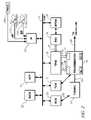
- FIG. 1is a schematic diagram of an exemplary hybrid powertrain, in accordance with the present disclosure
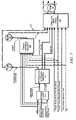
- FIG. 2is a schematic diagram of an exemplary architecture for a control system and hybrid powertrain, in accordance with the present disclosure
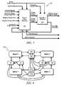
- FIGS. 3 , 4 and 5are schematic flow diagrams of a control scheme, in accordance with the present disclosure.
- FIG. 6is a process flow diagram of a state machine in accordance with the present disclosure.
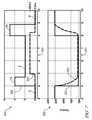
- FIG. 7is a graphical representation of engine states and engine torque in according with the present disclosure.
- FIGS. 1 and 2depict an exemplary hybrid powertrain.
- the exemplary hybrid powertrain in accordance with the present disclosureis depicted in FIG. 1 , comprising a two-mode, compound-split, electro-mechanical hybrid transmission 10 operatively connected to an engine 14 and first and second electric machines (‘MG-A’) 56 and (‘MG-B’) 72 .
- the engine 14 and first and second electric machines 56 and 72each generate power which can be transferred to the transmission 10 .
- the power generated by the engine 14 and the first and second electric machines 56 and 72 and transferred to the transmission 10is described in terms of input and motor torques, referred to herein as T I , T A , and T B respectively, and speed, referred to herein as N I , N A , and N B , respectively.
- the exemplary engine 14comprises a multi-cylinder internal combustion engine selectively operative in several states to transfer torque to the transmission 10 via an input shaft 12 , and can be either a spark-ignition or a compression-ignition engine.
- the engine 14includes a crankshaft (not shown) operatively coupled to the input shaft 12 of the transmission 10 .
- a rotational speed sensor 11monitors rotational speed of the input shaft 12 .
- Power output from the engine 14comprising rotational speed and engine torque, can differ from the input speed N I and the input torque T I to the transmission 10 due to placement of torque-consuming components on the input shaft 12 between the engine 14 and the transmission 10 , e.g., a hydraulic pump (not shown) and/or a torque management device (not shown).
- the exemplary transmission 10comprises three planetary-gear sets 24 , 26 and 28 , and four selectively engageable torque-transferring devices, i.e., clutches C 1 70 , C 2 62 , C 3 73 , and C 4 75 .
- clutchesrefer to any type of friction torque transfer device including single or compound plate clutches or packs, band clutches, and brakes, for example.
- a hydraulic control circuit 42preferably controlled by a transmission control module (hereafter ‘TCM’) 17 , is operative to control clutch states.
- Clutches C 2 62 and C 4 75preferably comprise hydraulically-applied rotating friction clutches.
- Clutches C 1 70 and C 3 73preferably comprise hydraulically-controlled stationary devices that can be selectively grounded to a transmission case 68 .
- Each of the clutches C 1 70 , C 2 62 , C 3 73 , and C 4 75is preferably hydraulically applied, selectively receiving pressurized hydraulic fluid via the hydraulic control circuit 42 .
- the first and second electric machines 56 and 72preferably comprise three-phase AC machines, each including a stator (not shown) and a rotor (not shown), and respective resolvers 80 and 82 .
- the motor stator for each machineis grounded to an outer portion of the transmission case 68 , and includes a stator core with coiled electrical windings extending therefrom.
- the rotor for the first electric machine 56is supported on a hub plate gear that is operatively attached to shaft 60 via the second planetary gear set 26 .
- the rotor for the second electric machine 72is fixedly attached to a sleeve shaft hub 66 .
- Each of the resolvers 80 and 82preferably comprises a variable reluctance device including a resolver stator (not shown) and a resolver rotor (not shown).
- the resolvers 80 and 82are appropriately positioned and assembled on respective ones of the first and second electric machines 56 and 72 .
- Stators of respective ones of the resolvers 80 and 82are operatively connected to one of the stators for the first and second electric machines 56 and 72 .
- the resolver rotorsare operatively connected to the rotor for the corresponding first and second electric machines 56 and 72 .
- Each of the resolvers 80 and 82is signally and operatively connected to a transmission power inverter control module (hereafter ‘TPIM’) 19 , and each senses and monitors rotational position of the resolver rotor relative to the resolver stator, thus monitoring rotational position of respective ones of first and second electric machines 56 and 72 . Additionally, the signals output from the resolvers 80 and 82 are interpreted to provide the rotational speeds for first and second electric machines 56 and 72 , i.e., N A and N B , respectively.
- TPIMtransmission power inverter control module
- the transmission 10includes an output member 64 , e.g. a shaft, which is operably connected to a driveline 90 for a vehicle (not shown), to provide output power to the driveline 90 that is transferred to vehicle wheels 93 , one of which is shown in FIG. 1 .
- the output power at the output member 64is characterized in terms of an output rotational speed N O and an output torque T O .
- a transmission output speed sensor 84monitors rotational speed and rotational direction of the output member 64 .
- Each of the vehicle wheels 93is preferably equipped with a sensor 94 adapted to monitor wheel speed, the output of which is monitored by a control module of a distributed control module system described with respect to FIG. 2 , to determine vehicle speed, and absolute and relative wheel speeds for braking control, traction control, and vehicle acceleration management.
- the input torque from the engine 14 and the motor torques from the first and second electric machines 56 and 72(T I , T A , and T B respectively) are generated as a result of energy conversion from fuel or electrical potential stored in an electrical energy storage device (hereafter ‘ESD’) 74 .
- the ESD 74is high voltage DC-coupled to the TPIM 19 via DC transfer conductors 27 .
- the transfer conductors 27include a contactor switch 38 . When the contactor switch 38 is closed, under normal operation, electric current can flow between the ESD 74 and the TPIM 19 . When the contactor switch 38 is opened electric current flow between the ESD 74 and the TPIM 19 is interrupted.
- the TPIM 19transmits electrical power to and from the first electric machine 56 by transfer conductors 29 , and the TPIM 19 similarly transmits electrical power to and from the second electric machine 72 by transfer conductors 31 to meet the torque commands for the first and second electric machines 56 and 72 in response to the motor torques T A and T B . Electrical current is transmitted to and from the ESD 74 in accordance with whether the ESD 74 is being charged or discharged.
- the TPIM 19includes the pair of power inverters (not shown) and respective motor control modules (not shown) configured to receive the torque commands and control inverter states therefrom for providing motor drive or regeneration functionality to meet the commanded motor torques T A and T B .
- the power inverterscomprise known complementary three-phase power electronics devices, and each includes a plurality of insulated gate bipolar transistors (not shown) for converting DC power from the ESD 74 to AC power for powering respective ones of the first and second electric machines 56 and 72 , by switching at high frequencies.
- the insulated gate bipolar transistorsform a switch mode power supply configured to receive control commands. There is typically one pair of insulated gate bipolar transistors for each phase of each of the three-phase electric machines.
- the three-phase invertersreceive or supply DC electric power via DC transfer conductors 27 and transform it to or from three-phase AC power, which is conducted to or from the first and second electric machines 56 and 72 for operation as motors or generators via transfer conductors 29 and 31 respectively.
- FIG. 2is a schematic block diagram of the distributed control module system.
- the elements described hereinaftercomprise a subset of an overall vehicle control architecture, and provide coordinated system control of the exemplary hybrid powertrain described in FIG. 1 .
- the distributed control module systemsynthesizes pertinent information and inputs, and executes algorithms to control various actuators to meet control objectives, including objectives related to fuel economy, emissions, performance, drivability, and protection of hardware, including batteries of ESD 74 and the first and second electric machines 56 and 72 .
- the distributed control module systemincludes an engine control module (hereafter ‘ECM’) 23 , the TCM 17 , a battery pack control module (hereafter ‘BPCM’) 21 , and the TPIM 19 .
- ECMengine control module
- BPCMbattery pack control module
- a hybrid control module (hereafter ‘HCP’) 5provides supervisory control and coordination of the ECM 23 , the TCM 17 , the BPCM 21 , and the TPIM 19 .
- a user interface (‘UI’) 13is operatively connected to a plurality of devices through which a vehicle operator controls or directs operation of the electro-mechanical hybrid powertrain.
- the devicesinclude an accelerator pedal 113 (‘AP’), an operator brake pedal 112 (‘BP’), a transmission gear selector 114 (‘PRNDL’), and a vehicle speed cruise control (not shown).
- the transmission gear selector 114may have a discrete number of operator-selectable positions, including the rotational direction of the output member 64 to enable one of a forward and a reverse direction.
- the aforementioned control modulescommunicate with other control modules, sensors, and actuators via a local area network (hereafter ‘LAN’) bus 6 .
- the LAN bus 6allows for structured communication of states of operating parameters and actuator command signals between the various control modules.
- the specific communication protocol utilizedis application-specific.
- the LAN bus 6 and appropriate protocolsprovide for robust messaging and multi-control module interfacing between the aforementioned control modules, and other control modules providing functionality including e.g., antilock braking, traction control, and vehicle stability.
- Multiple communications busesmay be used to improve communications speed and provide some level of signal redundancy and integrity. Communication between individual control modules can also be effected using a direct link, e.g., a serial peripheral interface (‘SPI’) bus (not shown).
- SPIserial peripheral interface
- the HCP 5provides supervisory control of the hybrid powertrain, serving to coordinate operation of the ECM 23 , TCM 17 , TPIM 19 , and BPCM 21 . Based upon various input signals from the user interface 13 and the hybrid powertrain, including the ESD 74 , the HCP 5 determines an operator torque request, an output torque command, an engine input torque command, clutch torque(s) for the applied torque-transfer clutches C 1 70 , C 2 62 , C 3 73 , C 4 75 of the transmission 10 , and the motor torques T A and T B for the first and second electric machines 56 and 72 .
- the ECM 23is operatively connected to the engine 14 , and functions to acquire data from sensors and control actuators of the engine 14 over a plurality of discrete lines, shown for simplicity as an aggregate bi-directional interface cable 35 .
- the ECM 23receives the engine input torque command from the HCP 5 .
- the ECM 23determines the actual engine input torque, T I , provided to the transmission 10 at that point in time based upon monitored engine speed and load, which is communicated to the HCP 5 .
- the ECM 23monitors input from the rotational speed sensor 11 to determine the engine input speed to the input shaft 12 , which translates to the transmission input speed, N I .
- the ECM 23monitors inputs from sensors (not shown) to determine states of other engine operating parameters including, e.g., a manifold pressure, engine coolant temperature, ambient air temperature, and ambient pressure.
- the engine loadcan be determined, for example, from the manifold pressure, or alternatively, from monitoring operator input to the accelerator pedal 113 .
- the ECM 23generates and communicates command signals to control engine actuators, including, e.g., fuel injectors, ignition modules, and throttle control modules, none of which are shown.
- the TCM 17is operatively connected to the transmission 10 and monitors inputs from sensors (not shown) to determine states of transmission operating parameters.
- the TCM 17generates and communicates command signals to control the transmission 10 , including controlling the hydraulic control circuit 42 .
- Inputs from the TCM 17 to the HCP 5include estimated clutch torques for each of the clutches, i.e., C 1 70 , C 2 62 , C 3 73 , and C 4 75 , and rotational output speed, N O , of the output member 64 .
- Other actuators and sensorsmay be used to provide additional information from the TCM 17 to the HCP 5 for control purposes.
- the TCM 17monitors inputs from pressure switches (not shown) and selectively actuates pressure control solenoids (not shown) and shift solenoids (not shown) of the hydraulic control circuit 42 to selectively actuate the various clutches C 1 70 , C 2 62 , C 3 73 , and C 4 75 to achieve various transmission operating range states, as described hereinbelow.
- the BPCM 21is signally connected to sensors (not shown) to monitor the ESD 74 , including states of electrical current and voltage parameters, to provide information indicative of parametric states of the batteries of the ESD 74 to the HCP 5 .
- the parametric states of the batteriespreferably include battery state-of-charge, battery voltage, battery temperature, and available battery power, referred to as a range P BAT — MIN to P BAT — MAX .
- a brake control module (hereafter ‘BrCM’) 22is operatively connected to friction brakes (not shown) on each of the vehicle wheels 93 .
- the BrCM 22monitors the operator input to the brake pedal 112 and generates control signals to control the friction brakes and sends a control signal to the HCP 5 to operate the first and second electric machines 56 and 72 based thereon.
- Each of the control modules ECM 23 , TCM 17 , TPIM 19 , BPCM 21 , and BrCM 22is preferably a general-purpose digital computer comprising a microprocessor or central processing unit, storage mediums comprising read only memory (‘ROM’), random access memory (‘RAM’), electrically programmable read only memory (‘EPROM’), a high speed clock, analog to digital (‘A/D’) and digital to analog (‘D/A’) circuitry, and input/output circuitry and devices (‘I/O’) and appropriate signal conditioning and buffer circuitry.
- Each of the control moduleshas a set of control algorithms, comprising resident program instructions and calibrations stored in one of the storage mediums and executed to provide the respective functions of each computer.
- control algorithmsare executed during preset loop cycles such that each algorithm is executed at least once each loop cycle.
- Algorithms stored in the non-volatile memory devicesare executed by one of the central processing units to monitor inputs from the sensing devices and execute control and diagnostic routines to control operation of the actuators, using preset calibrations.
- Loop cyclesare executed at regular intervals, for example each 3.125, 6.25, 12.5, 25 and 100 milliseconds during ongoing operation of the hybrid powertrain. Alternatively, algorithms may be executed in response to the occurrence of an event.
- the exemplary hybrid powertrainselectively operates in one of several states that can be described in terms of engine states comprising one of an engine-on state (‘ON’) and an engine-off state (‘OFF’), and transmission operating range states comprising a plurality of fixed gears and continuously variable operating modes, described with reference to Table 1, below.
- engine statescomprising one of an engine-on state (‘ON’) and an engine-off state (‘OFF’)
- transmission operating range statescomprising a plurality of fixed gears and continuously variable operating modes, described with reference to Table 1, below.
- Each of the transmission operating range statesis described in the table and indicates which of the specific clutches C 1 70 , C 2 62 , C 3 73 , and C 4 75 are applied for each of the operating range states.
- a first continuously variable modei.e., EVT Mode 1 , or M 1
- the engine statecan be one of ON (‘M 1 _Eng_On’) or OFF (‘M 1 _Eng_Off’).
- a second continuously variable modei.e., EVT Mode 2 , or M 2 , is selected by applying clutch C 2 62 only to connect the shaft 60 to the carrier of the third planetary gear set 28 .
- the engine statecan be one of ON (‘M 2 _Eng_On’) or OFF (‘M 2 _Eng_Off’).
- RPMrevolutions per minute
- a fixed gear operationprovides a fixed ratio operation of input-to-output speed of the transmission 10 , i.e., N I /N O .
- a first fixed gear operation(‘G1’) is selected by applying clutches C 1 70 and C 4 75 .
- a second fixed gear operation(‘G2’) is selected by applying clutches C 1 70 and C 2 62 .
- a third fixed gear operation(‘G3’) is selected by applying clutches C 2 62 and C 4 75 .
- a fourth fixed gear operation (‘G4’)is selected by applying clutches C 2 62 and C 3 73 .
- the fixed ratio operation of input-to-output speedincreases with increased fixed gear operation due to decreased gear ratios in the planetary gears 24 , 26 , and 28 .
- the rotational speeds of the first and second electric machines 56 and 72 , N A and N B respectively,are dependent on internal rotation of the mechanism as defined by the clutching and are proportional to the input speed measured at the input shaft 12 .
- the HCP 5 and one or more of the other control modulesdetermine torque commands to control the torque generative devices comprising the engine 14 and the first and second electric machines 56 and 72 to meet the operator torque request at the output member 64 and transferred to the driveline 90 .
- the HCP 5determines the operator torque request, a commanded output torque from the transmission 10 to the driveline 90 , an input torque from the engine 14 , clutch torques for the torque-transfer clutches C 1 70 , C 2 62 , C 3 73 , C 4 75 of the transmission 10 ; and the motor torques for the first and second electric machines 56 and 72 , respectively, as is described hereinbelow.
- Final vehicle accelerationcan be affected by other factors including, e.g., road load, road grade, and vehicle mass.
- the engine state and the transmission operating range stateare determined based upon a variety of operating characteristics of the hybrid powertrain. This includes the operator torque request communicated through the accelerator pedal 113 and brake pedal 112 to the user interface 13 as previously described.
- the transmission operating range state and the engine statemay be predicated on a hybrid powertrain torque demand caused by a command to operate the first and second electric machines 56 and 72 in an electrical energy generating mode or in a torque generating mode.
- the transmission operating range state and the engine statecan be determined by an optimization algorithm or routine which determines optimum system efficiency based upon operator demand for power, battery state of charge, and energy efficiencies of the engine 14 and the first and second electric machines 56 and 72 .
- the control systemmanages torque inputs from the engine 14 and the first and second electric machines 56 and 72 based upon an outcome of the executed optimization routine, and system efficiencies are optimized thereby, to manage fuel economy and battery charging. Furthermore, operation can be determined based upon a fault in a component or system.
- the HCP 5monitors the torque-generative devices, and determines the power output from the transmission 10 at output member 64 that is required to meet the operator torque request while meeting other powertrain operating demands, e.g., charging the ESD 74 .
- the ESD 74 and the first and second electric machines 56 and 72are electrically-operatively coupled for power flow therebetween. Furthermore, the engine 14 , the first and second electric machines 56 and 72 , and the electro-mechanical transmission 10 are mechanically-operatively coupled to transfer power therebetween to generate a power flow to the output member 64 .
- FIG. 3shows a control system architecture for controlling and managing signal flow in a hybrid powertrain system having multiple torque generative devices, described hereinbelow with reference to the hybrid powertrain system of FIGS. 1 and 2 , and residing in the aforementioned control modules in the form of executable algorithms and calibrations.
- the control system architectureis applicable to alternative hybrid powertrain systems having multiple torque generative devices, including, e.g., a hybrid powertrain system having an engine and a single electric machine, a hybrid powertrain system having an engine and multiple electric machines.
- the hybrid powertrain systemcan utilize non-electric torque-generative machines and energy storage systems, e.g., hydraulic-mechanical hybrid transmissions (not shown).
- the control system architectureshows signal flow of a plurality of inputs to a strategic optimization control scheme (‘Strategic Control’) 310 , which determines a preferred input speed (‘Ni_Des’) and a preferred operating range state (‘Hybrid Range State Des’) based upon the output speed and the operator torque request, and optimized based upon other operating parameters of the hybrid powertrain, including battery power limits and response limits of the engine 14 , transmission 10 , and first and second electric machines 56 and 72 .
- the strategic optimization control scheme 310is preferably executed by the HCP 5 during each 100 ms loop cycle and each 25 ms loop cycle.
- the outputs of the strategic optimization control scheme 310are used in a shift execution and engine start/stop control scheme (‘Shift Execution and Engine Start/Stop’) 320 to command changes in the operation of the transmission 10 (‘Transmission Commands’) including changing the operating range state.
- the present operating range state (‘Hybrid Range State Actual’) and an input speed profile (‘Ni_Prof’)can be determined.
- the input speed profileis an estimate of an upcoming time-rate change in the input speed and preferably comprises a scalar parametric value that is a targeted input speed for the forthcoming loop cycle, based upon the engine operating commands and the operator torque request during a transition in the operating range state of the transmission.
- a tactical control scheme (‘Tactical Control and Operation’) 330is repeatedly executed during one of the control loop cycles to determine engine commands (‘Engine Commands’) for operating the engine 14 , including a preferred input torque from the engine 14 to the transmission 10 based upon the output speed, the input speed, and the operator torque request and the present operating range state for the transmission.
- the engine commandsalso include engine states including one of an all-cylinder state and a cylinder deactivation state wherein a portion of the engine cylinders are deactivated and unfueled, and engine states including one of a fueled state and a fuel cutoff state.
- a clutch torque (‘Tcl’) for each of the clutches C 1 70 , C 2 62 , C 3 73 , and C 4 75is estimated in the TCM 17 , including the presently applied clutches and the non-applied clutches, and a present engine input torque (‘Ti’) reacting with the input member 12 is determined in the ECM 23 .
- a motor torque control scheme (‘Output and Motor Torque Determination’) 340is executed to determine the preferred output torque from the powertrain (‘To_cmd’), which includes motor torque commands (‘T A ’, ‘T B ’) for controlling the first and second electric machines 56 and 72 in this embodiment.
- the preferred output torqueis based upon the estimated clutch torque(s) for each of the clutches, the present input torque from the engine 14 , the present operating range state, the input speed, the operator torque request, and the input speed profile.
- the first and second electric machines 56 and 72are controlled through the TPIM 19 to meet the preferred motor torque commands based upon the preferred output torque.
- the motor torque control scheme 340includes algorithmic code which is regularly executed during the 6.25 ms and 12.5 ms loop cycles to determine the preferred motor torque commands.
- the hybrid powertrainis controlled to transfer the output torque to the output member 64 and thence to the driveline 90 to generate tractive torque at wheel(s) 93 to forwardly propel the vehicle in response to the operator input to the accelerator pedal 113 when the operator selected position of the transmission gear selector 114 commands operation of the vehicle in the forward direction.
- the hybrid powertrainis controlled to transfer the output torque to the output member 64 and thence to the driveline 90 to generate tractive torque at wheel(s) 93 to propel the vehicle in a reverse direction in response to the operator input to the accelerator pedal 113 when the operator selected position of the transmission gear selector 114 commands operation of the vehicle in the reverse direction.
- propelling the vehicleresults in vehicle acceleration so long as the output torque is sufficient to overcome external loads on the vehicle, e.g., due to road grade, aerodynamic loads, and other loads.
- the BrCM 22commands the friction brakes on the wheels 93 to apply braking force and generates a command for the transmission 10 to create a negative output torque which reacts with the driveline 90 in response to a net operator input to the brake pedal 112 and the accelerator pedal 113 .
- the applied braking force and the negative output torquecan decelerate and stop the vehicle so long as they are sufficient to overcome vehicle kinetic power at wheel(s) 93 .
- the negative output torquereacts with the driveline 90 , thus transferring torque to the electro-mechanical transmission 10 and the engine 14 .
- the negative output torque reacted through the electro-mechanical transmission 10can be transferred to the first and second electric machines 56 and 72 to generate electric power for storage in the ESD 74 .
- the operator inputs to the accelerator pedal 113 and the brake pedal 112comprise individually determinable operator torque request inputs including an immediate accelerator output torque request (‘Output Torque Request Accel Immed’), a predicted accelerator output torque request (‘Output Torque Request Accel Prdtd’), an immediate brake output torque request (‘Output Torque Request Brake Immed’), a predicted brake output torque request (‘Output Torque Request Brake Prdtd’) and an axle torque response type (‘Axle Torque Response Type’).
- the term ‘accelerator’refers to an operator request for forward propulsion preferably resulting in increasing vehicle speed over the present vehicle speed, when the operator selected position of the transmission gear selector 114 commands operation of the vehicle in the forward direction.
- the terms ‘deceleration’ and ‘brake’refer to an operator request preferably resulting in decreasing vehicle speed from the present vehicle speed.
- the immediate accelerator output torque request, the predicted accelerator output torque request, the immediate brake output torque request, the predicted brake output torque request, and the axle torque response typeare individual inputs to the control system including to the tactical control scheme 330 .
- the immediate accelerator output torque requestis determined based upon a presently occurring operator input to the accelerator pedal 113 , and comprises a request to generate an immediate output torque at the output member 64 preferably to accelerate the vehicle.
- the immediate accelerator output torque requestis unshaped, but can be shaped by events that affect vehicle operation outside the powertrain control. Such events include vehicle level interruptions in the powertrain control for antilock braking, traction control and vehicle stability control, which can be used to unshape or rate-limit the immediate accelerator output torque request.
- the predicted accelerator output torque requestis determined based upon the operator input to the accelerator pedal 113 and comprises an optimum or preferred output torque at the output member 64 .
- the predicted accelerator output torque requestis preferably equal to the immediate accelerator output torque request during normal operating conditions, e.g., when any one of antilock braking, traction control, or vehicle stability is not being commanded.
- the predicted accelerator output torque requestremains the preferred output torque with the immediate accelerator output torque request being decreased in response to output torque commands related to the antilock braking, traction control, or vehicle stability control.
- Blended brake torqueincludes a combination of the friction braking torque generated at the wheels 93 and the output torque generated at the output member 64 which reacts with the driveline 90 to decelerate the vehicle in response to the operator input to the brake pedal 112 .
- the immediate brake output torque requestis determined based upon a presently occurring operator input to the brake pedal 112 , and comprises a request to generate an immediate output torque at the output member 64 to effect a reactive torque with the driveline 90 which preferably decelerates the vehicle.
- the immediate brake output torque requestis determined based upon the operator input to the brake pedal 112 and the control signal to control the friction brakes to generate friction braking torque.
- the predicted brake output torque requestcomprises an optimum or preferred brake output torque at the output member 64 in response to an operator input to the brake pedal 112 subject to a maximum brake output torque generated at the output member 64 allowable regardless of the operator input to the brake pedal 112 .
- the maximum brake output torque generated at the output member 64is limited to ⁇ 0.2 g.
- the predicted brake output torque requestcan be phased out to zero when vehicle speed approaches zero regardless of the operator input to the brake pedal 112 .
- there can be operating conditions under which the predicted brake output torque request is set to zeroe.g., when the operator setting to the transmission gear selector 114 is set to a reverse gear, and when a transfer case (not shown) is set to a four-wheel drive low range.
- the operating conditions whereat the predicted brake output torque request is set to zeroare those in which blended braking is not preferred due to vehicle operating factors.
- the axle torque response typecomprises an input state for shaping and rate-limiting the output torque response through the first and second electric machines 56 and 72 .
- the input state for the axle torque response typecan be an active state, preferably comprising one of a pleasability limited state a maximum range state, and an inactive state.
- the output torque commandis the immediate output torque.
- the torque response for this response typeis as fast as possible.
- the predicted accelerator output torque request and the predicted brake output torque requestare input to the strategic optimization control scheme (‘Strategic Control’) 310 .
- the strategic optimization control scheme 310determines a desired operating range state for the transmission 10 (‘Hybrid Range State Des’) and a desired input speed from the engine 14 to the transmission 10 (‘Ni Des’), which comprise inputs to the shift execution and engine start/stop control scheme (‘Shift Execution and Engine Start/Stop’) 320 .
- a change in the input torque from the engine 14 which reacts with the input member from the transmission 10can be effected by changing mass of intake air to the engine 14 by controlling position of an engine throttle utilizing an electronic throttle control system (not shown), including opening the engine throttle to increase engine torque and closing the engine throttle to decrease engine torque.
- Changes in the input torque from the engine 14can be effected by adjusting ignition timing, including retarding spark timing from a mean-best-torque spark timing to decrease engine torque.
- the engine statecan be changed between the engine-off state and the engine-on state to effect a change in the input torque.
- the engine statecan be changed between the all-cylinder state and the cylinder deactivation state, wherein a portion of the engine cylinders are unfueled.
- the engine statecan be changed by selectively operating the engine 14 in one of the fueled state and the fuel cutoff state wherein the engine is rotating and unfueled. Executing a shift in the transmission 10 from a first operating range state to a second operating range state can be commanded and achieved by selectively applying and deactivating the clutches C 1 70 , C 2 62 , C 3 73 , and C 4 75 .
- FIG. 4details the tactical control scheme (‘Tactical Control and Operation’) 330 for controlling operation of the engine 14 , described with reference to the hybrid powertrain system of FIGS. 1 and 2 and the control system architecture of FIG. 3 .
- the tactical control scheme 330includes a tactical optimization control path 350 and a system constraints control path 360 which are preferably executed concurrently.
- the outputs of the tactical optimization control path 350are input to an engine state control scheme 370 .
- the outputs of the engine state control scheme 370 and the system constraints control path 360are input to an engine response type determination scheme (‘Engine Response Type Determination’) 380 for controlling the engine state, the immediate engine torque request and the predicted engine torque request.
- Engine Response Type Determinationengine response type determination scheme
- the operating point of the engine 14is described in terms of the input torque and input speed that can be achieved by controlling mass of intake air to the engine 14 when the engine 14 comprises a spark-ignition engine by controlling position of an engine throttle (not shown) utilizing an electronic throttle control device (not shown). This includes opening the throttle to increase the engine input speed and torque output and closing the throttle to decrease the engine input speed and torque.
- the engine operating pointcan be achieved by adjusting ignition timing, generally by retarding spark timing from a mean-best-torque spark timing to decrease engine torque.
- the operating point of the engine 14can be achieved by controlling the mass of injected fuel, and adjusted by retarding injection timing from a mean-best-torque injection timing to decrease engine torque.
- the engine operating pointcan be achieved by changing the engine state between the engine-off state and the engine-on state.
- the engine operating pointcan be achieved by controlling the engine state between the all-cylinder state and the cylinder deactivation state, wherein a portion of the engine cylinders are unfueled and the engine valves are deactivated.
- the engine statecan include the fuel cutoff state wherein the engine is rotating and unfueled to effect engine braking.
- the tactical optimization control path 350acts on substantially steady state inputs to select a preferred engine state and determine a preferred input torque from the engine 14 to the transmission 10 .
- the inputsoriginate in the shift execution and engine state control scheme 320 .
- the tactical optimization control path 350includes an optimization scheme (‘Tactical Optimization’) 354 to determine preferred input torques for operating the engine 14 in the all-cylinder state (‘Input Torque Full’), in the cylinder deactivation state (‘Input Torque Deac’), the all-cylinder state with fuel cutoff (‘Input Torque Full FCO’), in the cylinder deactivation state with fuel cutoff (‘Input Torque Deac FCO’), and a preferred engine state (‘Preferred Engine State’).
- Inputs to the optimization scheme 354include a lead operating range state of the transmission 10 (‘Lead Hybrid Range State’) a predicted lead input acceleration profile (‘Lead Input Acceleration Profile Predicted’), a predicted range of clutch reactive torques (‘Predicted Clutch Reactive Torque Min/Max’) for each presently applied clutch, predicted battery power limits (‘Predicted Battery Power Limits’) and predicted output torque requests for acceleration (‘Output Torque Request Accel Prdtd’) and braking (‘Output Torque Request Brake Prdtd’).
- the predicted output torque requests for acceleration and brakingare combined and shaped with the axle torque response type through a predicted output torque shaping filter 352 to yield a predicted net output torque request (‘To Net Prdtd’) and a predicted accelerator output torque request (‘To Accel Prdtd’), which are inputs to the optimization scheme 354 .
- the lead operating range state of the transmission 10comprises a time-shifted lead of the operating range state of the transmission 10 to accommodate a response time lag between a commanded change in the operating range state and a measured change in the operating range state.
- the predicted lead input acceleration profilecomprises a time-shifted lead of the predicted input acceleration profile of the input member 12 to accommodate a response time lag between a commanded change in the predicted input acceleration profile and a measured change in the predicted input acceleration profile.
- the optimization scheme 354determines costs for operating the engine 14 in the engine states, which comprise operating the engine fueled and in the all-cylinder state (‘P COST FULL FUEL ’), operating the engine unfueled and in the all-cylinder state (‘P COST FULL FCO ’), operating the engine fueled and in cylinder deactivation state (‘P COST DEAC FUEL ’), and operating the engine unfueled and in the cylinder deactivation state (‘P COST DEAC FCO ’).
- the aforementioned costs for operating the engine 14are input to a stabilization analysis scheme (‘Stabilization and Arbitration’) 356 along with the actual engine state (‘Actual Engine State’) and an allowable or permissible engine state (‘Engine State Allowed’) to select one of the engine states as the preferred engine state (‘Preferred Engine State’).
- Stabilization and Arbitrationa stabilization analysis scheme
- Engine State Allowedan allowable or permissible engine state
- the preferred input torques for operating the engine 14 in the all-cylinder state and in the cylinder deactivation state with and without fuel cutoffare input to an engine torque conversion calculator (‘Engine Torque Conversion’) 355 and converted to preferred engine torques in the all-cylinder state and in the cylinder deactivation state (‘Engine Torque Full’) and (‘Engine Torque Deac’) and with fuel cutoff in the all-cylinder state and in the cylinder deactivation state (‘Engine Torque Full FCO’) and (‘Engine Torque Deac FCO’) respectively, by taking into account parasitic and other loads introduced between the engine 14 and the transmission 10 .
- the preferred engine torques for operation in the all-cylinder state and in the cylinder deactivation state and the preferred engine statecomprise inputs to the engine state control scheme 370 .
- the costs for operating the engine 14include operating costs which are generally determined based upon factors that include vehicle driveability, fuel economy, emissions, and battery usage. Costs are assigned and associated with fuel and electrical power consumption and are associated with a specific operating points of the hybrid powertrain. Lower operating costs are generally associated with lower fuel consumption at high conversion efficiencies, lower battery power usage, and lower emissions for each engine speed/load operating point, and take into account the present state of the engine 14 .
- the preferred engine state and the preferred engine torques in the all-cylinder state and in the cylinder deactivation stateare input to the engine state control scheme 370 , which includes an engine state machine (‘Engine State Machine’) 372 .
- the engine state machine 372determines a target engine torque (‘Target Engine Torque’) and a target engine state (‘Target Engine State’) based upon the preferred engine torques and the preferred engine state.
- the target engine torque and the target engine stateare input to a transition filter (‘Transition Filtering’) 374 which monitors any commanded transition in the engine state and filters the target engine torque to provide a filtered target engine torque (‘Filtered Target Engine Torque’).
- the engine state machine 372outputs a command that indicates selection of one of the cylinder deactivation state and the all-cylinder state (‘DEAC Selected’) and indicates selection of one of the engine-on state and the deceleration fuel cutoff state (‘FCO Selected’).
- the selection of one of the cylinder deactivation state and the all-cylinder state and the selection of one of the engine-on state and the deceleration fuel cutoff state, the filtered target engine torque, and the minimum and maximum engine torquesare input to the engine response type determination scheme 380 .
- the system constraints control path 360determines constraints on the input torque, comprising minimum and maximum input torques (‘Input Torque Hybrid Minimum’ and ‘Input Torque Hybrid Maximum’) that can be reacted by the transmission 10 .
- the minimum and maximum input torquesare determined based upon constraints to the transmission 10 and the first and second electric machines 56 and 72 , including clutch torques and battery power limits, which affect the capacity of the transmission 10 to react input torque during the current loop cycle.
- Inputs to the system constraints control path 360include the immediate output torque request as measured by the accelerator pedal 113 (‘Output Torque Request Accel Immed’) and the immediate output torque request as measured by the brake pedal 112 (‘Output Torque Request Brake Immed’) which are combined and shaped with the axle torque response type through an immediate output torque shaping filter (‘Immediate Output Torque Shaping’) 362 to yield a net immediate output torque (‘To Net Immed’) and an immediate accelerator output torque (‘To Accel Immed’).
- the net immediate output torque and the immediate accelerator output torqueare inputs to a constraints scheme (‘Output and Input Torque Constraints’) 364 .
- Other inputs to the constraints scheme 364include the lead operating range state of the transmission 10 , an immediate lead input acceleration profile (‘Lead Input Acceleration Profile Immed’), a lead immediate clutch reactive torque range (‘Lead Immediate Clutch Reactive Torque Min/Max’) for each presently applied clutch, and the available battery power (‘Battery Power Limits’) comprising the range P BAT — MIN to P BAT — MAX .
- the immediate lead input acceleration profilecomprises a time-shifted lead of the immediate input acceleration profile of the input member 12 to accommodate a response time lag between a commanded change in the immediate input acceleration profile and a measured change in the immediate input acceleration profile.
- the lead immediate clutch reactive torque rangecomprises a time-shifted lead of the immediate clutch reactive torque range of the clutches to accommodate a response time lag between a commanded change in the immediate clutch torque range and a measured change in the immediate clutch reactive torque range.
- the constraints scheme 364determines an output torque range for the transmission 10 , and then determines the minimum and maximum allowable input torques (‘Input Torque Hybrid Minimum’ and ‘Input Torque Hybrid Maximum’ respectively) that can be reacted by the transmission 10 based upon the aforementioned inputs.
- the minimum and maximum allowable input torquescan change during ongoing operation, due to changes in the aforementioned inputs, including increasing energy recovery through electric power regeneration through the transmission 14 and first and second electric machines 56 and 72 .
- the minimum and maximum allowable input torquesare input to the engine torque conversion calculator 355 and converted to minimum and maximum engine torques (‘Engine Torque Hybrid Minimum’ and ‘Engine Torque Hybrid Maximum’ respectively), by taking into account parasitic and other loads introduced between the engine 14 and the transmission 10 .
- the filtered target engine torque, the output of the engine state machine 372 and the minimum and maximum engine torquesare input to the engine response type determination scheme 380 , which inputs the engine commands to the ECM 23 for controlling the engine state, the immediate engine torque request and the predicted engine torque request.
- the engine commandsinclude an immediate engine torque request (‘Engine Torque Request Immed’) and a predicted engine torque request (‘Engine Torque Request Prdtd’) that can be determined based upon the filtered target engine torque.
- Other commandscontrol the engine state to one of the engine fueled state and the deceleration fuel cutoff state (‘FCO Request’) and to one of the cylinder deactivation state and the all-cylinder state (‘DEAC Request’).
- Another outputcomprises an engine response type (‘Engine Response Type’).
- the engine response typeWhen the filtered target engine torque is within the range between the minimum and maximum engine torques, the engine response type is inactive. When the filtered target engine torque is outside the constraints of the minimum and maximum engine torques (‘Engine Torque Hybrid Minimum’) and (‘Engine Torque Hybrid Maximum’) the engine response type is active, indicating a need for an immediate change in the engine torque, e.g., through engine spark control and retard to change the engine torque and the input torque to fall within the constraints of the minimum and maximum engine torques.
- FIG. 5depicts the engine state control scheme 370 including the engine state machine 372 and the transition filter 374 .
- the preferred engine state(‘Preferred Engine State’) is input to the engine state machine 372 .
- the engine state machine 372selects and outputs a target engine state (‘Target Engine State’) and a target engine torque (‘Target Engine Torque’) based on the preferred engine state.
- FIG. 6shows permissible states of an exemplary state machine including a plurality of main states (‘State 0 ’, ‘State 1 ’, ‘State 2 ’, and ‘State 3 ’) and a plurality of transition states (T 4 , T 5 , T 6 , T 7 , T 8 , T 9 , T 12 , and T 13 ).
- main states and transition statespreferably correspond to engine states.
- the main statesinclude a first main state corresponding to engine operation in the fueled, all-cylinder engine state (hereafter ‘State 0 ’), a second main state corresponding to engine operation in the all-cylinder engine state with fuel cutoff (hereafter, ‘State 1 ’), a third main state corresponding to the cylinder deactivation engine state (hereafter, ‘State 2 ’), and a fourth main state corresponding to the engine in the cylinder deactivation engine state with fuel cutoff (hereafter, ‘State 3 ’).
- Other inputs to the engine state machine 372include the engine torques from the optimization scheme 354 for each of the engine states converted from the corresponding input torques for each of the main states.
- the engine state machine 372inputs the preferred engine torque corresponding to state 0 (‘Engine Torque Full’), the engine torque corresponding to state 1 (‘Engine Torque Full FCO’), the preferred engine torque corresponding to state 2 (‘Engine Torque Deac’), and the engine torque corresponding to state 3 (‘Engine Torque Deac FCO’).
- the engine state machine 372further inputs state enablement information (‘Enable Bits’), the present or actual engine state (‘Actual Engine State’) and the state of the transition (‘Transition Completed’).
- the transition filter 374generates a signal comprising the state of the transition to indicate whether specific engine states are enabled, thus permitting transition thereto.
- the transition filter 374includes information indicating whether the transition to the target engine state can be completed.
- the engine state machine 372determines and outputs the target engine state (‘Target Engine State’) and sends signals indicating selection of the cylinder deactivation state (‘DEAC Selected’) and indicating selection of the fuel cutoff state (‘FCO Selected’). Further, the engine state machine 372 determines and outputs the target engine torque (‘Target Engine Torque’) comprising the engine torque corresponding to the target engine state. This includes an upcoming transition engine state and a corresponding transition engine torque following a transition path determined by the state machine.
- the engine state machine 372includes the transition paths, e.g., as shown in FIG. 6 , for controlling transitions between the main states including the transition states between the main states.
- the transition pathsinclude a transition path from the fueled, all-cylinder state to the fueled, cylinder deactivation state (hereafter “state T 4 ”), a transition path from the fueled, cylinder deactivation state to the fueled, all-cylinder state (hereafter “state T 5 ”), a transition path from the fueled, all-cylinder state to the fuel-cutoff, all-cylinder state (hereafter “state T 6 ”), a transition path from the fuel-cutoff, all-cylinder state to the fueled, all-cylinder state (hereafter “state T 7 ”), a transition path from the fueled, cylinder deactivation state to the fuel-cutoff, cylinder deactivation state (hereafter “state T 8 ”), a transition path from the fuel-cutoff, cylinder deactivation state to the fueled, cylinder deactivation
- the engine state machine 372selects a preferred transition path based on the present engine state and the target engine state. If the enablement information indicates that one of the transition states of the preferred transition path is not available, the engine state machine 372 can determine an alternate transition path. For example, the engine state machine 372 can determine a preferred transition path between state 3 and state 0 comprising transitioning from state 3 to state T 9 , then to state 2 , then to state T 5 , and then to state 0 . However, if the enablement information indicates that cylinder deactivation is unavailable, the engine state machine 372 can determine an alternate transition path comprising transitioning from state 3 to state T 5 , then to state 0 .
- the engine state machine 372continuously monitors the preferred engine state when in a transition state, and can thereby determine a transition path that connects directly between two transition states. For example, if the engine state machine 372 detects a change in the preferred engine state to state 0 when the state is the transition state T 4 , the engine state machine determines a transition path to transition from state T 4 to state T 5 , and from state T 5 to state 0 .
- the transition filter 374includes a first order, low pass filter to determine and manage the engine torque during an engine state transition.
- the filtercan be described by Eq. 1:
- y ⁇ ( t )[ u ⁇ ( t ) - y ⁇ ( t - 1 ) ] ⁇ dT T + y ⁇ ( t - 1 ) [ 1 ]
- yis the filtered target engine torque
- dTis a sample time
- Tis a filter time constant.
- the filter time constant Tis determined utilizing the state of the state machine 372 , the target engine torque, the preferred engine state, the filtered target engine torque and the actual engine state. By utilizing inputs to determine the filter time constant T, a low pass filter of transition filter 374 provides a change in the input torque over a minimum transition time without causing sudden undesired torque changes when transitioning between states.
- the low pass filterdeviates from a standard low pass filter by providing a minimum incremental change in the engine torque. This minimum incremental change causes a transition from a low pass filter response to a ramp as y(t) approaches u(t), resulting in shorter transition times.
- the transition filter 374adjusts incrementally to the target engine torque and outputs the filtered target engine torque for controlling operation of the engine 14 .
- the main state enablement informationcomprising ‘Transition Complete’ indicates that the filtered target engine torque substantially coincides with the target engine torque and that therefore a transition from the present engine state to the target engine state can take place. While the engine state machine 372 is in one of the transition states T 4 , T 5 , T 6 , T 7 , T 8 , T 9 , T 12 , T 13 , the selections of the target engine state and of the target engine torque are coordinated.
- the transition filter 374incrementally adjusts the engine torque to the preferred engine torque of states 2 and 3 , respectively, prior to transitioning the engine from the all-cylinder state to the cylinder deactivation state.
- the state machine 372is in one of the transition states T 5 and T 12 , the state machine 372 first transitions the target engine state from the cylinder deactivation state to the all-cylinder state and then adjusts the engine torque to the preferred engine torque of main states 0 and 1 respectively.
- the transition filter 374incrementally adjusts filtered target engine torque to the preferred engine torque of states 1 and 3 respectively prior to transitioning the engine from the fueled engine state to the fuel cutoff state.
- the state machineis in one of the transition states T 7 and T 9 , the state machine 372 first transitions the target engine state from the fuel cutoff state to the fueled state and then adjusts the filtered target engine torque to the preferred engine torque of the main states 0 and 2 respectively.
- FIG. 7shows exemplary data comprising engine state and engine torque for the system described herein, depicting engine state transitions and corresponding engine torque.
- a first graph 600depicts the state 602 output from by the state machine 372 and an engine state 604 being one of the all-cylinder state and the cylinder deactivation state over a time period 605 .
- FIG. 7shows graph 620 depicting the target engine torque 622 output from the state machine 372 and the filtered target engine torque 624 output from the transition filter 372 over the time period 605 corresponding to the state 602 .
- the engine state machine 372determines a state 602 comprising state T 4 in response to a commanded change in the preferred engine state from state 0 to state 2 .
- the state 602transitions from main state 0 to state T 4 .
- the filtered torque 622is incrementally adjusted using Eqs. 1-2 above to transition from the target engine torque 620 of the preferred engine torque of main state 0 to the target engine torque 620 of the preferred engine torque of main state 2 .
- the transition to main state enablement informationsignals the engine state machine 372 to transition to state 2 .
- the actual cylinder deactivationcan be delayed 100-200 milliseconds after transitioning into main state 2 and the output of the cylinder deactivation state command by the engine state machine 372 .
- state machine 372When the engine state machine 372 subsequently determines a state 602 equal to state T 5 (not shown) in response to a change in the preferred engine state from state 2 to state 0 .
- the state 602transitions from state 2 to state T 5 .
- state T 5the transition from cylinder deactivation state to all cylinder state is commanded and achieved after a delay of 100-200 milliseconds.
- the filtered torque 622is incrementally adjusted using Eqs. 1-2 above to transition between the target engine torque 620 of the preferred engine torque of state 2 and the target engine torque 620 of the preferred torque of state 0 .
- the transition to main state enablement informationsignals the engine state machine 372 to transition from T 5 to state 0 .
Landscapes
- Engineering & Computer Science (AREA)
- Chemical & Material Sciences (AREA)
- Combustion & Propulsion (AREA)
- Transportation (AREA)
- Mechanical Engineering (AREA)
- Automation & Control Theory (AREA)
- Hybrid Electric Vehicles (AREA)
- Electric Propulsion And Braking For Vehicles (AREA)
- Control Of Vehicle Engines Or Engines For Specific Uses (AREA)
Abstract
Description
| TABLE 1 | |||
| Engine | Transmission Operating | Applied | |
| Description | State | Range State | Clutches |
| M1_Eng_Off | EVT Mode | 1 | |||
| M1_Eng_On | EVT Mode | 1 | |||
| G1 | ON | ||||
| G2 | ON | ||||
| M2_Eng_Off | EVT Mode | 2 | |||
| M2_Eng_On | EVT Mode | 2 | |||
| G3 | ON | ||||
| G4 | ON | ||||
wherein y is the filtered target engine torque,
Claims (18)
Priority Applications (3)
| Application Number | Priority Date | Filing Date | Title |
|---|---|---|---|
| US12/253,988US8131437B2 (en) | 2007-11-02 | 2008-10-19 | Method for operating a powertrain system to transition between engine states |
| EP08019046.5AEP2055574B1 (en) | 2007-11-02 | 2008-10-30 | Method for operating a powertrain system to transition between engine states |
| CN2008101898948ACN101497337B (en) | 2007-11-02 | 2008-10-31 | Method for operating a powertrain system to transition between engine states |
Applications Claiming Priority (2)
| Application Number | Priority Date | Filing Date | Title |
|---|---|---|---|
| US98497007P | 2007-11-02 | 2007-11-02 | |
| US12/253,988US8131437B2 (en) | 2007-11-02 | 2008-10-19 | Method for operating a powertrain system to transition between engine states |
Publications (2)
| Publication Number | Publication Date |
|---|---|
| US20090118937A1 US20090118937A1 (en) | 2009-05-07 |
| US8131437B2true US8131437B2 (en) | 2012-03-06 |
Family
ID=40427354
Family Applications (1)
| Application Number | Title | Priority Date | Filing Date |
|---|---|---|---|
| US12/253,988Active2030-10-18US8131437B2 (en) | 2007-11-02 | 2008-10-19 | Method for operating a powertrain system to transition between engine states |
Country Status (3)
| Country | Link |
|---|---|
| US (1) | US8131437B2 (en) |
| EP (1) | EP2055574B1 (en) |
| CN (1) | CN101497337B (en) |
Cited By (1)
| Publication number | Priority date | Publication date | Assignee | Title |
|---|---|---|---|---|
| US9212616B2 (en) | 2012-07-13 | 2015-12-15 | Robert Bosch Gmbh | Fuel shut-off command with adaptive cruise control |
Families Citing this family (124)
| Publication number | Priority date | Publication date | Assignee | Title |
|---|---|---|---|---|
| US8390240B2 (en) | 2007-08-06 | 2013-03-05 | GM Global Technology Operations LLC | Absolute position sensor for field-oriented control of an induction motor |
| US7867135B2 (en) | 2007-09-26 | 2011-01-11 | GM Global Technology Operations LLC | Electro-mechanical transmission control system |
| US8234048B2 (en) | 2007-10-19 | 2012-07-31 | GM Global Technology Operations LLC | Method and system for inhibiting operation in a commanded operating range state for a transmission of a powertrain system |
| US8060267B2 (en) | 2007-10-23 | 2011-11-15 | GM Global Technology Operations LLC | Method for controlling power flow within a powertrain system |
| US9140337B2 (en) | 2007-10-23 | 2015-09-22 | GM Global Technology Operations LLC | Method for model based clutch control and torque estimation |
| US8187145B2 (en) | 2007-10-25 | 2012-05-29 | GM Global Technology Operations LLC | Method and apparatus for clutch torque control in mode and fixed gear for a hybrid powertrain system |
| US8335623B2 (en) | 2007-10-25 | 2012-12-18 | GM Global Technology Operations LLC | Method and apparatus for remediation of and recovery from a clutch slip event in a hybrid powertrain system |
| US8296027B2 (en) | 2007-10-25 | 2012-10-23 | GM Global Technology Operations LLC | Method and apparatus to control off-going clutch torque during torque phase for a hybrid powertrain system |
| US8118122B2 (en) | 2007-10-25 | 2012-02-21 | GM Global Technology Operations LLC | Method and system for monitoring signal integrity in a distributed controls system |
| US8265821B2 (en) | 2007-10-25 | 2012-09-11 | GM Global Technology Operations LLC | Method for determining a voltage level across an electric circuit of a powertrain |
| US8406945B2 (en) | 2007-10-26 | 2013-03-26 | GM Global Technology Operations LLC | Method and apparatus to control logic valves for hydraulic flow control in an electro-mechanical transmission |
| US8167773B2 (en) | 2007-10-26 | 2012-05-01 | GM Global Technology Operations LLC | Method and apparatus to control motor cooling in an electro-mechanical transmission |
| US8548703B2 (en) | 2007-10-26 | 2013-10-01 | GM Global Technology Operations LLC | Method and apparatus to determine clutch slippage in an electro-mechanical transmission |
| US8204702B2 (en) | 2007-10-26 | 2012-06-19 | GM Global Technology Operations LLC | Method for estimating battery life in a hybrid powertrain |
| US9097337B2 (en) | 2007-10-26 | 2015-08-04 | GM Global Technology Operations LLC | Method and apparatus to control hydraulic line pressure in an electro-mechanical transmission |
| US7985154B2 (en)* | 2007-10-26 | 2011-07-26 | GM Global Technology Operations LLC | Method and apparatus to control hydraulic pressure for component lubrication in an electro-mechanical transmission |
| US8560191B2 (en) | 2007-10-26 | 2013-10-15 | GM Global Technology Operations LLC | Method and apparatus to control clutch pressures in an electro-mechanical transmission |
| US8303463B2 (en) | 2007-10-26 | 2012-11-06 | GM Global Technology Operations LLC | Method and apparatus to control clutch fill pressure in an electro-mechanical transmission |
| US8428816B2 (en) | 2007-10-27 | 2013-04-23 | GM Global Technology Operations LLC | Method and apparatus for monitoring software and signal integrity in a distributed control module system for a powertrain system |
| US8244426B2 (en) | 2007-10-27 | 2012-08-14 | GM Global Technology Operations LLC | Method and apparatus for monitoring processor integrity in a distributed control module system for a powertrain system |
| US8062174B2 (en) | 2007-10-27 | 2011-11-22 | GM Global Technology Operations LLC | Method and apparatus to control clutch stroke volume in an electro-mechanical transmission |
| US8099219B2 (en) | 2007-10-27 | 2012-01-17 | GM Global Technology Operations LLC | Method and apparatus for securing an operating range state mechanical transmission |
| US8290681B2 (en) | 2007-10-29 | 2012-10-16 | GM Global Technology Operations LLC | Method and apparatus to produce a smooth input speed profile in mode for a hybrid powertrain system |
| US8489293B2 (en) | 2007-10-29 | 2013-07-16 | GM Global Technology Operations LLC | Method and apparatus to control input speed profile during inertia speed phase for a hybrid powertrain system |
| US8095254B2 (en) | 2007-10-29 | 2012-01-10 | GM Global Technology Operations LLC | Method for determining a power constraint for controlling a powertrain system |
| US8170762B2 (en) | 2007-10-29 | 2012-05-01 | GM Global Technology Operations LLC | Method and apparatus to control operation of a hydraulic pump for an electro-mechanical transmission |
| US8282526B2 (en) | 2007-10-29 | 2012-10-09 | GM Global Technology Operations LLC | Method and apparatus to create a pseudo torque phase during oncoming clutch engagement to prevent clutch slip for a hybrid powertrain system |
| US8209098B2 (en) | 2007-10-29 | 2012-06-26 | GM Global Technology Operations LLC | Method and apparatus for monitoring a transmission range selector in a hybrid powertrain transmission |
| US8112194B2 (en) | 2007-10-29 | 2012-02-07 | GM Global Technology Operations LLC | Method and apparatus for monitoring regenerative operation in a hybrid powertrain system |
| US8073602B2 (en) | 2007-11-01 | 2011-12-06 | GM Global Technology Operations LLC | System constraints method of controlling operation of an electro-mechanical transmission with an additional constraint range |
| US8035324B2 (en) | 2007-11-01 | 2011-10-11 | GM Global Technology Operations LLC | Method for determining an achievable torque operating region for a transmission |
| US7977896B2 (en) | 2007-11-01 | 2011-07-12 | GM Global Technology Operations LLC | Method of determining torque limit with motor torque and battery power constraints |
| US8145375B2 (en) | 2007-11-01 | 2012-03-27 | GM Global Technology Operations LLC | System constraints method of determining minimum and maximum torque limits for an electro-mechanical powertrain system |
| US8556011B2 (en) | 2007-11-01 | 2013-10-15 | GM Global Technology Operations LLC | Prediction strategy for thermal management and protection of power electronic hardware |
| US8133151B2 (en) | 2007-11-02 | 2012-03-13 | GM Global Technology Operations LLC | System constraints method of controlling operation of an electro-mechanical transmission with an additional constraint |
| US8121765B2 (en) | 2007-11-02 | 2012-02-21 | GM Global Technology Operations LLC | System constraints method of controlling operation of an electro-mechanical transmission with two external input torque ranges |
| US8825320B2 (en) | 2007-11-02 | 2014-09-02 | GM Global Technology Operations LLC | Method and apparatus for developing a deceleration-based synchronous shift schedule |
| US8847426B2 (en)* | 2007-11-02 | 2014-09-30 | GM Global Technology Operations LLC | Method for managing electric power in a powertrain system |
| US8585540B2 (en) | 2007-11-02 | 2013-11-19 | GM Global Technology Operations LLC | Control system for engine torque management for a hybrid powertrain system |
| US8287426B2 (en) | 2007-11-02 | 2012-10-16 | GM Global Technology Operations LLC | Method for controlling voltage within a powertrain system |
| US8170764B2 (en) | 2007-11-02 | 2012-05-01 | GM Global Technology Operations LLC | Method and apparatus to reprofile input speed during speed during speed phase during constrained conditions for a hybrid powertrain system |
| US8121767B2 (en) | 2007-11-02 | 2012-02-21 | GM Global Technology Operations LLC | Predicted and immediate output torque control architecture for a hybrid powertrain system |
| US8200403B2 (en) | 2007-11-02 | 2012-06-12 | GM Global Technology Operations LLC | Method for controlling input torque provided to a transmission |
| US8224539B2 (en) | 2007-11-02 | 2012-07-17 | GM Global Technology Operations LLC | Method for altitude-compensated transmission shift scheduling |
| US8204664B2 (en) | 2007-11-03 | 2012-06-19 | GM Global Technology Operations LLC | Method for controlling regenerative braking in a vehicle |
| US8285431B2 (en) | 2007-11-03 | 2012-10-09 | GM Global Technology Operations LLC | Optimal selection of hybrid range state and/or input speed with a blended braking system in a hybrid electric vehicle |
| US8224514B2 (en) | 2007-11-03 | 2012-07-17 | GM Global Technology Operations LLC | Creation and depletion of short term power capability in a hybrid electric vehicle |
| US8010247B2 (en) | 2007-11-03 | 2011-08-30 | GM Global Technology Operations LLC | Method for operating an engine in a hybrid powertrain system |
| US8296021B2 (en) | 2007-11-03 | 2012-10-23 | GM Global Technology Operations LLC | Method for determining constraints on input torque in a hybrid transmission |
| US8135526B2 (en) | 2007-11-03 | 2012-03-13 | GM Global Technology Operations LLC | Method for controlling regenerative braking and friction braking |
| US8155814B2 (en) | 2007-11-03 | 2012-04-10 | GM Global Technology Operations LLC | Method of operating a vehicle utilizing regenerative braking |
| US8002667B2 (en) | 2007-11-03 | 2011-08-23 | GM Global Technology Operations LLC | Method for determining input speed acceleration limits in a hybrid transmission |
| US8406970B2 (en) | 2007-11-03 | 2013-03-26 | GM Global Technology Operations LLC | Method for stabilization of optimal input speed in mode for a hybrid powertrain system |
| US8260511B2 (en) | 2007-11-03 | 2012-09-04 | GM Global Technology Operations LLC | Method for stabilization of mode and fixed gear for a hybrid powertrain system |
| US8068966B2 (en) | 2007-11-03 | 2011-11-29 | GM Global Technology Operations LLC | Method for monitoring an auxiliary pump for a hybrid powertrain |
| US8868252B2 (en) | 2007-11-03 | 2014-10-21 | GM Global Technology Operations LLC | Control architecture and method for two-dimensional optimization of input speed and input power including search windowing |
| US8346449B2 (en) | 2007-11-04 | 2013-01-01 | GM Global Technology Operations LLC | Method and apparatus to provide necessary output torque reserve by selection of hybrid range state and input speed for a hybrid powertrain system |
| US8000866B2 (en) | 2007-11-04 | 2011-08-16 | GM Global Technology Operations LLC | Engine control system for torque management in a hybrid powertrain system |
| US8214093B2 (en) | 2007-11-04 | 2012-07-03 | GM Global Technology Operations LLC | Method and apparatus to prioritize transmission output torque and input acceleration for a hybrid powertrain system |
| US8818660B2 (en) | 2007-11-04 | 2014-08-26 | GM Global Technology Operations LLC | Method for managing lash in a driveline |
| US8112206B2 (en) | 2007-11-04 | 2012-02-07 | GM Global Technology Operations LLC | Method for controlling a powertrain system based upon energy storage device temperature |
| US8126624B2 (en) | 2007-11-04 | 2012-02-28 | GM Global Technology Operations LLC | Method for selection of optimal mode and gear and input speed for preselect or tap up/down operation |
| US8092339B2 (en) | 2007-11-04 | 2012-01-10 | GM Global Technology Operations LLC | Method and apparatus to prioritize input acceleration and clutch synchronization performance in neutral for a hybrid powertrain system |
| US8214120B2 (en) | 2007-11-04 | 2012-07-03 | GM Global Technology Operations LLC | Method to manage a high voltage system in a hybrid powertrain system |
| US8098041B2 (en) | 2007-11-04 | 2012-01-17 | GM Global Technology Operations LLC | Method of charging a powertrain |
| US8079933B2 (en) | 2007-11-04 | 2011-12-20 | GM Global Technology Operations LLC | Method and apparatus to control engine torque to peak main pressure for a hybrid powertrain system |
| US8067908B2 (en) | 2007-11-04 | 2011-11-29 | GM Global Technology Operations LLC | Method for electric power boosting in a powertrain system |
| US8594867B2 (en) | 2007-11-04 | 2013-11-26 | GM Global Technology Operations LLC | System architecture for a blended braking system in a hybrid powertrain system |
| US8374758B2 (en) | 2007-11-04 | 2013-02-12 | GM Global Technology Operations LLC | Method for developing a trip cost structure to understand input speed trip for a hybrid powertrain system |
| US8504259B2 (en) | 2007-11-04 | 2013-08-06 | GM Global Technology Operations LLC | Method for determining inertia effects for a hybrid powertrain system |
| US8396634B2 (en) | 2007-11-04 | 2013-03-12 | GM Global Technology Operations LLC | Method and apparatus for maximum and minimum output torque performance by selection of hybrid range state and input speed for a hybrid powertrain system |
| US8135532B2 (en) | 2007-11-04 | 2012-03-13 | GM Global Technology Operations LLC | Method for controlling output power of an energy storage device in a powertrain system |
| US8897975B2 (en) | 2007-11-04 | 2014-11-25 | GM Global Technology Operations LLC | Method for controlling a powertrain system based on penalty costs |
| US8002665B2 (en) | 2007-11-04 | 2011-08-23 | GM Global Technology Operations LLC | Method for controlling power actuators in a hybrid powertrain system |
| US8200383B2 (en) | 2007-11-04 | 2012-06-12 | GM Global Technology Operations LLC | Method for controlling a powertrain system based upon torque machine temperature |
| US8138703B2 (en) | 2007-11-04 | 2012-03-20 | GM Global Technology Operations LLC | Method and apparatus for constraining output torque in a hybrid powertrain system |
| US8494732B2 (en) | 2007-11-04 | 2013-07-23 | GM Global Technology Operations LLC | Method for determining a preferred engine operation in a hybrid powertrain system during blended braking |
| US7988594B2 (en) | 2007-11-04 | 2011-08-02 | GM Global Technology Operations LLC | Method for load-based stabilization of mode and fixed gear operation of a hybrid powertrain system |
| US8414449B2 (en) | 2007-11-04 | 2013-04-09 | GM Global Technology Operations LLC | Method and apparatus to perform asynchronous shifts with oncoming slipping clutch torque for a hybrid powertrain system |
| US8095282B2 (en) | 2007-11-04 | 2012-01-10 | GM Global Technology Operations LLC | Method and apparatus for soft costing input speed and output speed in mode and fixed gear as function of system temperatures for cold and hot operation for a hybrid powertrain system |
| US8204656B2 (en) | 2007-11-04 | 2012-06-19 | GM Global Technology Operations LLC | Control architecture for output torque shaping and motor torque determination for a hybrid powertrain system |
| US8214114B2 (en) | 2007-11-04 | 2012-07-03 | GM Global Technology Operations LLC | Control of engine torque for traction and stability control events for a hybrid powertrain system |
| US8248023B2 (en) | 2007-11-04 | 2012-08-21 | GM Global Technology Operations LLC | Method of externally charging a powertrain |
| US8112192B2 (en) | 2007-11-04 | 2012-02-07 | GM Global Technology Operations LLC | Method for managing electric power within a powertrain system |
| US8118903B2 (en) | 2007-11-04 | 2012-02-21 | GM Global Technology Operations LLC | Method for preferential selection of modes and gear with inertia effects for a hybrid powertrain system |
| US8121766B2 (en) | 2007-11-04 | 2012-02-21 | GM Global Technology Operations LLC | Method for operating an internal combustion engine to transmit power to a driveline |
| US8221285B2 (en) | 2007-11-04 | 2012-07-17 | GM Global Technology Operations LLC | Method and apparatus to offload offgoing clutch torque with asynchronous oncoming clutch torque, engine and motor torque for a hybrid powertrain system |
| US9008926B2 (en) | 2007-11-04 | 2015-04-14 | GM Global Technology Operations LLC | Control of engine torque during upshift and downshift torque phase for a hybrid powertrain system |
| US8145397B2 (en) | 2007-11-04 | 2012-03-27 | GM Global Technology Operations LLC | Optimal selection of blended braking capacity for a hybrid electric vehicle |
| US8630776B2 (en) | 2007-11-04 | 2014-01-14 | GM Global Technology Operations LLC | Method for controlling an engine of a hybrid powertrain in a fuel enrichment mode |
| US8448731B2 (en) | 2007-11-05 | 2013-05-28 | GM Global Technology Operations LLC | Method and apparatus for determination of fast actuating engine torque for a hybrid powertrain system |
| US8229633B2 (en) | 2007-11-05 | 2012-07-24 | GM Global Technology Operations LLC | Method for operating a powertrain system to control engine stabilization |
| US8135519B2 (en) | 2007-11-05 | 2012-03-13 | GM Global Technology Operations LLC | Method and apparatus to determine a preferred output torque for operating a hybrid transmission in a fixed gear operating range state |
| US8321100B2 (en) | 2007-11-05 | 2012-11-27 | GM Global Technology Operations LLC | Method and apparatus for dynamic output torque limiting for a hybrid powertrain system |
| US8285462B2 (en) | 2007-11-05 | 2012-10-09 | GM Global Technology Operations LLC | Method and apparatus to determine a preferred output torque in mode and fixed gear operation with clutch torque constraints for a hybrid powertrain system |
| US8070647B2 (en) | 2007-11-05 | 2011-12-06 | GM Global Technology Operations LLC | Method and apparatus for adapting engine operation in a hybrid powertrain system for active driveline damping |
| US8099204B2 (en) | 2007-11-05 | 2012-01-17 | GM Global Technology Operatons LLC | Method for controlling electric boost in a hybrid powertrain |
| US8155815B2 (en) | 2007-11-05 | 2012-04-10 | Gm Global Technology Operation Llc | Method and apparatus for securing output torque in a distributed control module system for a powertrain system |
| US8160761B2 (en) | 2007-11-05 | 2012-04-17 | GM Global Technology Operations LLC | Method for predicting an operator torque request of a hybrid powertrain system |
| US8112207B2 (en) | 2007-11-05 | 2012-02-07 | GM Global Technology Operations LLC | Method and apparatus to determine a preferred output torque for operating a hybrid transmission in a continuously variable mode |
| US8121768B2 (en) | 2007-11-05 | 2012-02-21 | GM Global Technology Operations LLC | Method for controlling a hybrid powertrain system based upon hydraulic pressure and clutch reactive torque capacity |
| US8249766B2 (en) | 2007-11-05 | 2012-08-21 | GM Global Technology Operations LLC | Method of determining output torque limits of a hybrid transmission operating in a fixed gear operating range state |
| US8073601B2 (en) | 2007-11-05 | 2011-12-06 | GM Global Technology Operations LLC | Method for preferential selection of mode and gear and input speed based on multiple engine state fueling costs for a hybrid powertrain system |
| US8219303B2 (en) | 2007-11-05 | 2012-07-10 | GM Global Technology Operations LLC | Method for operating an internal combustion engine for a hybrid powertrain system |
| US8285432B2 (en) | 2007-11-05 | 2012-10-09 | GM Global Technology Operations LLC | Method and apparatus for developing a control architecture for coordinating shift execution and engine torque control |
| US8165777B2 (en) | 2007-11-05 | 2012-04-24 | GM Global Technology Operations LLC | Method to compensate for transmission spin loss for a hybrid powertrain system |
| US8281885B2 (en) | 2007-11-06 | 2012-10-09 | GM Global Technology Operations LLC | Method and apparatus to monitor rotational speeds in an electro-mechanical transmission |
| US8179127B2 (en) | 2007-11-06 | 2012-05-15 | GM Global Technology Operations LLC | Method and apparatus to monitor position of a rotatable shaft |
| US8271173B2 (en) | 2007-11-07 | 2012-09-18 | GM Global Technology Operations LLC | Method and apparatus for controlling a hybrid powertrain system |
| US8195349B2 (en) | 2007-11-07 | 2012-06-05 | GM Global Technology Operations LLC | Method for predicting a speed output of a hybrid powertrain system |
| US8433486B2 (en) | 2007-11-07 | 2013-04-30 | GM Global Technology Operations LLC | Method and apparatus to determine a preferred operating point for an engine of a powertrain system using an iterative search |
| US8267837B2 (en) | 2007-11-07 | 2012-09-18 | GM Global Technology Operations LLC | Method and apparatus to control engine temperature for a hybrid powertrain |
| US8277363B2 (en) | 2007-11-07 | 2012-10-02 | GM Global Technology Operations LLC | Method and apparatus to control temperature of an exhaust aftertreatment system for a hybrid powertrain |
| US8209097B2 (en) | 2007-11-07 | 2012-06-26 | GM Global Technology Operations LLC | Method and control architecture to determine motor torque split in fixed gear operation for a hybrid powertrain system |
| US8073610B2 (en) | 2007-11-07 | 2011-12-06 | GM Global Technology Operations LLC | Method and apparatus to control warm-up of an exhaust aftertreatment system for a hybrid powertrain |
| US9050970B2 (en)* | 2010-10-26 | 2015-06-09 | Nissan Motor Co., Ltd. | Driving torque control device for hybrid vehicle |
| US8989930B2 (en)* | 2011-06-17 | 2015-03-24 | GM Global Technology Operations LLC | Method and apparatus for controlling an engine disconnect clutch in a powertrain system |
| US8827865B2 (en) | 2011-08-31 | 2014-09-09 | GM Global Technology Operations LLC | Control system for a hybrid powertrain system |
| DE102013200191A1 (en)* | 2012-01-12 | 2013-07-18 | GM Global Technology Operations LLC (n. d. Gesetzen des Staates Delaware) | Method for controlling supply of fuel to motor in hybrid vehicle, involves generating request to operate motor in fuel cut-off (FCO) state, and determining fault in oxygen sensor based on response to transition process |
| US8801567B2 (en) | 2012-02-17 | 2014-08-12 | GM Global Technology Operations LLC | Method and apparatus for executing an asynchronous clutch-to-clutch shift in a hybrid transmission |
| US8523735B1 (en)* | 2012-02-23 | 2013-09-03 | GM Global Technology Operations LLC | Method and apparatus for executing a shift in a hybrid transmission |
| US9026327B2 (en)* | 2012-05-02 | 2015-05-05 | GM Global Technology Operations LLC | Method and apparatus for executing a shift path to a target powertrain state |
| JP6137135B2 (en)* | 2014-11-20 | 2017-05-31 | トヨタ自動車株式会社 | Vehicle drive control device |
| JP2024003883A (en)* | 2022-06-28 | 2024-01-16 | トヨタ自動車株式会社 | Vehicle control device |
Citations (207)
| Publication number | Priority date | Publication date | Assignee | Title |
|---|---|---|---|---|
| US6832148B1 (en) | 2003-10-14 | 2004-12-14 | General Motors Corporation | Automatic engine stop and restart mode for reducing emissions of a hybrid electric vehicle |
| US6868318B1 (en) | 2003-10-14 | 2005-03-15 | General Motors Corporation | Method for adjusting battery power limits in a hybrid electric vehicle to provide consistent launch characteristics |
| US20050080538A1 (en) | 2003-10-14 | 2005-04-14 | Hubbard Gregory A. | Real-time operating parameter selection in a vehicular transmission |
| US20050080527A1 (en) | 2003-10-14 | 2005-04-14 | Tao Xuefeng T. | Hybrid transmission member speed determination, sensor diagnostics and fault recovery |
| US20050080540A1 (en) | 2003-10-14 | 2005-04-14 | Steinmetz Todd M. | Synchronous shift control in an electrically variable transmission |
| US20050080539A1 (en) | 2003-10-14 | 2005-04-14 | Hubbard Gregory A. | Method for determining preferred input operating points for a vehicle transmission |
| US20050077877A1 (en) | 2003-10-14 | 2005-04-14 | Cawthorne William R. | Managing service life of a battery |
| US20050080541A1 (en) | 2003-10-14 | 2005-04-14 | Sah Jy-Jen F. | Two clutch fixed-ratio exit control for multi-mode hybrid drive |
| US20050080523A1 (en) | 2003-10-14 | 2005-04-14 | Bennett Adam C. | Silent operating mode for reducing emissions of a hybrid electric vehicle |
| US20050077867A1 (en) | 2003-10-14 | 2005-04-14 | Cawthorne William R. | Method of determining battery power limits for an energy storage system of a hybrid electric vehicle |
| US20050080535A1 (en) | 2003-10-14 | 2005-04-14 | Steinmetz Todd M. | Speed control for an electrically variable transmission |
| US20050080537A1 (en) | 2003-10-14 | 2005-04-14 | Cawthorne William R. | Optimal selection of input torque considering battery utilization for a hybrid electric vehicle |
| US20050076958A1 (en) | 2003-10-14 | 2005-04-14 | Foster Michael D. | Control apparatus, method and diagnostic for hydraulic fill and drain |
| US20050182547A1 (en) | 2004-02-14 | 2005-08-18 | Sah Jy-Jen F. | Shift inhibit control for multi-mode hybrid drive |
| US20050182546A1 (en) | 2004-02-14 | 2005-08-18 | Tung-Ming Hsieh | Throttle phase out control |
| US20050182526A1 (en) | 2004-02-14 | 2005-08-18 | Hubbard Gregory A. | Optimal selection of input torque with stability of power flow for a hybrid electric vehicle |
| US20050182543A1 (en) | 2004-02-14 | 2005-08-18 | Sah Jy-Jen F. | Shift through neutral control in an electrically variable transmission |
| US20050189918A1 (en) | 2004-02-14 | 2005-09-01 | Weisgerber Scott T. | Energy storage system state of charge diagnostic |
| US20050255963A1 (en) | 2004-05-14 | 2005-11-17 | Tung-Ming Hsieh | Single motor recovery for an electrically variable transmission |
| US20050255965A1 (en) | 2004-05-14 | 2005-11-17 | Tao Xuefeng T | Coordinated regenerative and engine retard braking for a hybrid vehicle |
| US20050256625A1 (en) | 2004-05-15 | 2005-11-17 | Sah Jy-Jen F | Hydraulic clutch state diagnostic and control |
| US20050256626A1 (en) | 2004-05-14 | 2005-11-17 | Tung-Ming Hsieh | Method and apparatus to control hydraulic pressure in an electrically variable transmission |
| US20050255966A1 (en) | 2004-05-14 | 2005-11-17 | Tao Xuefeng T | Engine retard operation scheduling and management in a hybrid vehicle |
| US20050255967A1 (en) | 2004-05-14 | 2005-11-17 | Foster Michael D | Method of automatically flushing debris from an electrically-operated hydraulic valve |
| US20050256623A1 (en) | 2004-05-15 | 2005-11-17 | Hubbard Gregory A | Method for dynamically determining peak output torque within battery constraints in a hybrid transmission including a parallel hybrid split |
| US20050256919A1 (en) | 2004-05-14 | 2005-11-17 | Cawthorne William R | Method of determining the derivative of an input signal |
| US20050256617A1 (en) | 2004-05-14 | 2005-11-17 | Cawthorne William R | Method of undervoltage protection during engine cranking |
| US20050252474A1 (en) | 2004-05-14 | 2005-11-17 | Sah Jy-Jen F | Multi-stage compression ignition engine start |
| US20050256627A1 (en) | 2004-05-14 | 2005-11-17 | Sah Jy-Jen F | Acceleration limiting for a vehicle |
| US20050252305A1 (en) | 2004-05-15 | 2005-11-17 | Hubbard Gregory A | Method for dynamically determining peak output torque in an electrically variable transmission |
| US20050256629A1 (en) | 2004-05-14 | 2005-11-17 | Tao Xuefeng T | Method for automatic traction control in a hybrid electric vehicle |
| US20050252283A1 (en) | 2004-05-14 | 2005-11-17 | Heap Anthony H | Diagnostic method for a torque control of an electrically variable transmission |
| US20050255964A1 (en) | 2004-05-15 | 2005-11-17 | Heap Anthony H | Method of providing electric motor torque reserve in a hybrid electric vehicle |
| US20050256631A1 (en) | 2004-05-14 | 2005-11-17 | Cawthorne William R | Method of determining engine output power in a hybrid electric vehicle |
| US20050256618A1 (en) | 2004-05-14 | 2005-11-17 | Tung-Ming Hsieh | Method of testing motor torque integrity in a hybrid electric vehicle |
| US20050256633A1 (en) | 2004-05-15 | 2005-11-17 | Heap Anthony H | Cost structure method including fuel economy and engine emission considerations |
| US20050255968A1 (en) | 2004-05-14 | 2005-11-17 | Sah Jy-Jen F | Method for active engine stop of a hybrid electric vehicle |
| US7154236B1 (en) | 2006-02-13 | 2006-12-26 | Gm Global Technology Operations, Inc. | Control system for hybrid powertrain |
| US20070149348A1 (en) | 2005-12-23 | 2007-06-28 | Holmes Alan G | Vehicle propulsion system |
| US20070191181A1 (en) | 2006-02-13 | 2007-08-16 | Burns Robert D | Method and apparatus for controlling vehicle rollback |
| US20070225888A1 (en) | 2006-03-22 | 2007-09-27 | Morris Robert L | Driveline lash estimation and clunk management using multivariable active driveline damping |
| US20070225886A1 (en) | 2006-03-22 | 2007-09-27 | Morris Robert L | Parameter state estimation |
| US20070225889A1 (en) | 2006-03-22 | 2007-09-27 | Morris Robert L | Jerk management using multivariable active driveline damping |
| US20070225887A1 (en) | 2006-03-22 | 2007-09-27 | Morris Robert L | Method and apparatus for multivariate active driveline damping |
| US20070260381A1 (en) | 2006-05-03 | 2007-11-08 | Sah Jy-Jen F | Synchronous shift execution for hybrid transmission |
| US20070276569A1 (en) | 2006-05-25 | 2007-11-29 | Sah Jy-Jen F | Method and apparatus to control an electro-mechanical transmission during shifting event |
| US20070284176A1 (en) | 2006-05-25 | 2007-12-13 | Sah Jy-Jen F | Method and apparatus to control hydraulic pressure in an electro-mechanical transmission |
| US20070285063A1 (en) | 2006-06-07 | 2007-12-13 | Zettel Andrew M | Method and apparatus for quantifying quiescent period temperature effects upon an electric energy storage device |
| US20070285097A1 (en) | 2006-06-07 | 2007-12-13 | Zettel Andrew M | Method and apparatus for predicting change in an operating state of an electric energy storage device |
| US20070285061A1 (en) | 2006-06-07 | 2007-12-13 | Zettel Andrew M | Method and apparatus for real-time life estimation of an electric energy storage device in a hybrid electric vehicle |
| US20070284162A1 (en) | 2006-06-07 | 2007-12-13 | Zettel Andrew M | Method for operating a hybrid electric powertrain based on predictive effects upon an electrical energy storage device |
| US20070284163A1 (en) | 2006-06-07 | 2007-12-13 | Heap Anthony H | Method and apparatus for control of a hybrid electric vehicle to achieve a target life objective for an energy storage device |
| US20070285060A1 (en) | 2006-06-07 | 2007-12-13 | Zettel Andrew M | Method and apparatus for determining the effect of temperature upon life expectancy of an electric energy storage device in a hybrid electric vehicle |
| US20070285059A1 (en) | 2006-06-07 | 2007-12-13 | Zettel Andrew M | Method and apparatus for real-time life estimation of an electric energy storage device |
| US20080004779A1 (en) | 2006-06-30 | 2008-01-03 | Sah Jy-Jen F | Apparatus and method to control transmission torque output during a gear-to-gear shift |
| US20080028879A1 (en) | 2006-08-04 | 2008-02-07 | Robinette Richard E | Method and apparatus for fault-tolerant transmission gear selector lever position determination |
| US20080032855A1 (en) | 2006-08-04 | 2008-02-07 | Sah Jy-Jen F | Method and apparatus to control an electro-hydraulic transmission during shifting event |
| US20080064559A1 (en) | 2006-09-11 | 2008-03-13 | Cawthorne William R | Control system architecture for a hybrid powertrain |
| US20080064562A1 (en) | 2006-09-13 | 2008-03-13 | Aettel Andrew M | Method and apparatus to monitor operation of an auxiliary hydraulic pump in a transmission |
| US20080103003A1 (en) | 2006-10-26 | 2008-05-01 | Sah Jy-Jen F | Method and apparatus to control operation of a hydraulic control circuit for an electro-mechanical transmission |
| US20080120002A1 (en) | 2006-11-17 | 2008-05-22 | Heap Anthony H | Control architecture and method for two-dimensional optimization of input speed and input torque in mode for a hybrid powertrain system |
| US20080119321A1 (en) | 2006-11-17 | 2008-05-22 | Heap Anthony H | Control architecture and method for two-dimensional optimization of input torque and motor torque in fixed gear for a hybrid powertrain system |
| US20080119320A1 (en) | 2006-11-17 | 2008-05-22 | Wu Peter E | Method and apparatus for controlling an electro-mechanical transmission during a shift execution |
| US20080120000A1 (en) | 2006-11-17 | 2008-05-22 | Heap Anthony H | Control architecture for optimization and control of a hybrid powertrain system |
| US20080120001A1 (en) | 2006-11-17 | 2008-05-22 | Heap Anthony H | Control architecture for selection of optimal mode or gear and input speed for a hybrid powertrain system |
| US20080176706A1 (en) | 2007-01-24 | 2008-07-24 | Wu Peter E | Method and apparatus to control operation of an electro-mechanical transmission |
| US20080176709A1 (en) | 2007-01-24 | 2008-07-24 | Wu Peter E | Method and apparatus to monitor devices of a hydraulic circuit of an electro-mechanical transmission |
| US20080182696A1 (en) | 2006-08-04 | 2008-07-31 | Sah Jy-Jen F | Method and apparatus to control operation of a hydraulic control circuit for an electro-mechanical transmission |
| US20080181280A1 (en) | 2007-01-31 | 2008-07-31 | Wang Wei D | Method and apparatus to monitor a temperature sensing device |
| US20080183372A1 (en) | 2007-01-31 | 2008-07-31 | Snyder Bryan R | Method and apparatus to determine pressure in an unfired cylinder |
| US20080234097A1 (en) | 2007-03-20 | 2008-09-25 | Sah Jy-Jen F | Clutch control for hybrid transmission |
| US20080236921A1 (en) | 2007-03-29 | 2008-10-02 | Huseman Steven C | Method for controlling engine speed in a hybrid electric vehicle |
| US20080243346A1 (en) | 2007-03-29 | 2008-10-02 | Huseman Steven C | Method and apparatus for controlling power flow in a hybrid powertrain system |
| US20080249745A1 (en) | 2006-06-07 | 2008-10-09 | Heap Anthony H | Method and apparatus for management of an electric energy storage device to achieve a target life objective |
| US20080262694A1 (en) | 2007-04-19 | 2008-10-23 | Heap Anthony H | Method and apparatus to optimize engine warm up |
| US20080262698A1 (en) | 2007-04-19 | 2008-10-23 | Lahti John L | Method and apparatus to determine instantaneous engine power loss for a powertrain system |
| US20080275625A1 (en) | 2007-05-03 | 2008-11-06 | Snyder Bryan R | Method and apparatus to control engine stop for a hybrid powertrain system |
| US20080275624A1 (en) | 2007-05-03 | 2008-11-06 | Snyder Bryan R | Method and apparatus to control engine restart for a hybrid powertrain system |
| US20080275611A1 (en) | 2007-05-03 | 2008-11-06 | Snyder Bryan R | Method and apparatus to determine rotational position of an internal combustion engine |
| US20080272717A1 (en) | 2007-05-03 | 2008-11-06 | Gleason Sean E | Method and apparatus to determine rotational position of an electrical machine |
| US20080287255A1 (en) | 2007-05-14 | 2008-11-20 | Snyder Bryan R | Control architecture and method to evaluate engine off operation of a hybrid powertrain system operating in a continuously variable mode |
| US20090069148A1 (en) | 2007-09-11 | 2009-03-12 | Heap Anthony H | Control architecture and method for one-dimensional optimization of input torque and motor torque in fixed gear for a hybrid powertrain system |
| US20090069989A1 (en) | 2007-09-11 | 2009-03-12 | Heap Anthony H | Method and control architecture for selection of optimal engine input torque for a powertrain system |
| US20090070019A1 (en) | 2007-09-11 | 2009-03-12 | Heap Anthony H | Method and control architecture for optimization of engine fuel-cutoff selection and engine input torque for a hybrid powertrain system |
| US20090082170A1 (en) | 2007-09-26 | 2009-03-26 | Gm Global Technology Operations, Inc. | Method and control architecture for optimization of cylinder deactivation selection and engine input torque for a hybrid powertrain system |
| US20090088294A1 (en) | 2007-09-28 | 2009-04-02 | Gm Global Technology Operations, Inc. | Thermal protection of an electric drive system |
| US20090105896A1 (en) | 2007-10-23 | 2009-04-23 | Gm Global Technology Operations, Inc. | Method for controlling power flow within a powertrain system |
| US20090105914A1 (en) | 2007-10-19 | 2009-04-23 | Gm Global Technology Operations, Inc. | Method and system for inhibiting operation in a commanded operating range state for a transmission of a powertrain system |
| US20090105039A1 (en) | 2007-10-23 | 2009-04-23 | Gm Global Technlogy Operations, Inc. | Method for model based clutch control and torque estimation |
| US20090105898A1 (en) | 2007-10-23 | 2009-04-23 | Gm Global Technology Operations, Inc. | Method for monitoring a motor speed sensor |
| US20090112399A1 (en) | 2007-10-27 | 2009-04-30 | Gm Global Technology Operations, Inc. | Method and apparatus for monitoring software and signal integrity in a distributed control module system for a powertrain system |
| US20090112417A1 (en) | 2007-10-29 | 2009-04-30 | Gm Global Technology Operations, Inc. | Method and apparatus to produce a smooth input speed profile in mode for a hybrid powertrain system |
| US20090112392A1 (en) | 2007-10-27 | 2009-04-30 | Gm Global Technology Operations, Inc. | Method and apparatus for monitoring processor integrity in a distributed control module system for a powertrain system |
| US20090112420A1 (en) | 2007-10-29 | 2009-04-30 | Gm Global Technology Operations, Inc. | Method and apparatus for monitoring a transmission range selector in a hybrid powertrain transmission |
| US20090111642A1 (en) | 2007-10-27 | 2009-04-30 | Gm Global Technology Operations, Inc. | Method and apparatus to control clutch stroke volume in an electro-mechanical transmission |
| US20090112385A1 (en) | 2007-10-29 | 2009-04-30 | Gm Global Technology Operations, Inc. | Method for determining a power constraint for controlling a powertrain system |
| US20090111644A1 (en) | 2007-10-25 | 2009-04-30 | Gm Global Technology Operations, Inc. | Method and apparatus for clutch torque control in mode and fixed gear for a hybrid powertrain system |
| US20090111645A1 (en) | 2007-10-29 | 2009-04-30 | Gm Global Technology Operations, Inc. | Method and apparatus to create a pseudo torque phase during oncoming clutch engagement to prevent clutch slip for a hybrid powertrain system |
| US20090112412A1 (en) | 2007-10-31 | 2009-04-30 | Gm Global Technology Operations, Inc. | Method and apparatus to monitor output of an electro-mechanical transmission |
| US20090112416A1 (en) | 2007-10-29 | 2009-04-30 | Gm Global Technology Operations, Inc. | Method and apparatus to control input speed profile during inertia speed phase for a hybrid powertrain system |
| US20090112419A1 (en) | 2007-10-25 | 2009-04-30 | Gm Global Technology Operations, Inc. | Method and apparatus to control off-going clutch torque during torque phase for a hybrid powertrain system |
| US20090112421A1 (en) | 2007-10-26 | 2009-04-30 | Gm Global Technology Operations, Inc. | Method and apparatus to control hydraulic line pressure in an electro-mechanical transmission |
| US20090111643A1 (en) | 2007-10-26 | 2009-04-30 | Gm Global Technology Operations, Inc. | Method and apparatus to control clutch fill pressure in an electro-mechanical transmission |
| US20090112423A1 (en) | 2007-10-29 | 2009-04-30 | Gm Global Technology Operations, Inc. | Method and apparatus to control operation of a hydraulic pump for an electro-mechanical transmission |
| US20090112427A1 (en) | 2007-10-25 | 2009-04-30 | Gm Global Technology Operations, Inc. | Method and apparatus for remediation of and recovery from a clutch slip event in a hybrid powertrain system |
| US20090108673A1 (en) | 2007-10-25 | 2009-04-30 | Gm Globaltechnology Operations, Inc. | Method for determining a voltage level across an electric circuit of a powertrain |
| US20090112418A1 (en) | 2007-10-27 | 2009-04-30 | Gm Global Technology Operations, Inc. | Method and apparatus for securing an operating range state mechanical transmission |
| US20090112422A1 (en) | 2007-10-26 | 2009-04-30 | Gm Global Technology Operations, Inc. | Method and apparatus to control logic valves for hydraulic flow control in an electro-mechanical transmission |
| US20090112495A1 (en) | 2007-10-26 | 2009-04-30 | Gm Global Technology Operations, Inc. | Method for estimating battery life in a hybrid powertrain |
| US20090111640A1 (en) | 2007-10-29 | 2009-04-30 | Gm Global Technology Operations, Inc. | Method and apparatus for monitoring regenerative operation in a hybrid powertrain system |
| US20090112429A1 (en) | 2007-10-26 | 2009-04-30 | Gm Global Technology Operations, Inc. | Method and apparatus to control clutch pressures in an electro-mechanical transmission |
| US20090107755A1 (en) | 2007-10-26 | 2009-04-30 | Gm Global Technology Operations, Inc. | Method and apparatus to control motor cooling in an electro-mechanical transmission |
| US20090111637A1 (en) | 2007-10-26 | 2009-04-30 | Gm Global Technology Operations, Inc. | Method and apparatus to control hydraulic pressure for component lubrication in an electro-mechanical transmission |
| US20090112428A1 (en) | 2007-10-26 | 2009-04-30 | Gm Global Technology Operations, Inc. | Method and apparatus to determine clutch slippage in an electro-mechanical transmission |
| US20090107745A1 (en) | 2007-10-25 | 2009-04-30 | Gm Global Technology Operations, Inc. | Method and system for monitoring signal integrity in a distributed controls system |
| US20090118914A1 (en) | 2007-11-05 | 2009-05-07 | Gm Global Technology Operations, Inc. | Method for operating an internal combustion engine for a hybrid powertrain system |
| US20090118957A1 (en) | 2007-11-04 | 2009-05-07 | Gm Global Technology Operations, Inc. | Optimal selection of blended braking capacity for a hybrid electric vehicle |
| US20090115350A1 (en) | 2007-11-01 | 2009-05-07 | Gm Global Technology Operations, Inc. | Method for determining an achievable torque operating region for a transmission |
| US20090118923A1 (en) | 2007-11-04 | 2009-05-07 | Gm Global Technology Operations, Inc. | Method for controlling a powertrain system based on penalty costs |
| US20090118948A1 (en) | 2007-11-04 | 2009-05-07 | Gm Global Technology Operations, Inc. | Method and apparatus for maximum and minimum output torque performance by selection of hybrid range state and input speed for a hybrid powertrain system |
| US20090118951A1 (en) | 2007-11-04 | 2009-05-07 | Gm Global Technology Operations, Inc. | Method for developing a trip cost structure to understand input speed trip for a hybrid powertrain system |
| US20090118091A1 (en) | 2007-11-07 | 2009-05-07 | Gm Global Technology Operations, Inc. | Method and apparatus to control temperature of an exhaust aftertreatment system for a hybrid powertrain |
| US20090118882A1 (en) | 2007-11-04 | 2009-05-07 | Gm Global Technology Operations, Inc. | Control architecture for output torque shaping and motor torque determination for a hybrid powertrain system |
| US20090118940A1 (en) | 2007-11-05 | 2009-05-07 | Gm Global Technology Operations, Inc. | Method for operating a powertrain system to control engine stabilization |
| US20090115352A1 (en) | 2007-11-04 | 2009-05-07 | Gm Global Technology Operations, Inc. | Method and apparatus for constraining output torque in a hybrid powertrain system |
| US20090118952A1 (en) | 2007-11-03 | 2009-05-07 | Gm Global Technology Operations, Inc. | Control architecture and method for two-dimensional optimization of input speed and input power including search windowing |
| US20090118093A1 (en) | 2007-11-02 | 2009-05-07 | Gm Global Technology Oprations, Inc. | Control system for engine torque management for a hybrid powertrain system |
| US20090118933A1 (en) | 2007-11-05 | 2009-05-07 | Gm Global Technology Operations, Inc. | Method to compensate for transmission spin loss for a hybrid powertrain system |
| US20090118950A1 (en) | 2007-11-05 | 2009-05-07 | Gm Global Technology Operations, Inc. | Method and apparatus to determine a preferred output torque for operating a hybrid transmission in a continuously variable mode |
| US20090118945A1 (en) | 2007-11-04 | 2009-05-07 | Gm Global Technology Operations, Inc. | Method for managing lash in a driveline |
| US20090118080A1 (en) | 2007-11-04 | 2009-05-07 | Gm Global Technology Operations, Inc. | Method for managing electric power within a powertrain system |
| US20090118079A1 (en) | 2007-11-02 | 2009-05-07 | Gm Global Technology Operations, Inc. | Method for controlling voltage within a powertrain system |
| US20090115373A1 (en) | 2007-11-04 | 2009-05-07 | Gm Global Technology Operations, Inc. | Method of charging a powertrain |
| US20090115365A1 (en) | 2007-11-01 | 2009-05-07 | Gm Global Technology Operations, Inc. | Method of determining torque limit with motor torque and battery power constraints |
| US20090118880A1 (en) | 2007-11-07 | 2009-05-07 | Gm Global Technology Operations, Inc. | Method for predicting a speed output of a hybrid powertrain system |
| US20090118918A1 (en) | 2007-11-03 | 2009-05-07 | Gm Global Technology Operations, Inc. | Method for stabilization of optimal input speed in mode for a hybrid powertrain system |
| US20090118086A1 (en) | 2007-11-04 | 2009-05-07 | Gm Global Technology Operations, Inc. | Method and apparatus to offload offgoing clutch torque with asynchronous oncoming clutch torque, engine and motor torque for a hybrid powertrain system |
| US20090118925A1 (en) | 2007-11-02 | 2009-05-07 | Gm Global Technology Operations, Inc. | System constraints method of controlling operation of an electro-mechanical transmission with two external input torque ranges |
| US20090118887A1 (en) | 2007-11-03 | 2009-05-07 | Gm Global Technology Operations, Inc. | Method for controlling regenerative braking and friction braking |
| US20090118931A1 (en) | 2007-11-02 | 2009-05-07 | Gm Global Technology Operations, Inc. | Method and apparatus to reprofile input speed during speed phase during constrained conditions for a hybrid powertrain system |
| US20090118094A1 (en) | 2007-11-03 | 2009-05-07 | Gm Global Technology Operations, Inc. | Method for determining input speed acceleration limits in a hybrid transmission |
| US20090118935A1 (en) | 2007-11-05 | 2009-05-07 | Gm Global Technology Operations, Inc. | Method for controlling a hybrid powertrain system based upon hydraulic pressure and clutch reactive torque capacity |
| US20090118077A1 (en) | 2007-11-02 | 2009-05-07 | Gm Global Technology Operations, Inc. | System constraints method of controlling operation of an electro-mechanical transmission with an additional constraint |
| US20090118969A1 (en) | 2007-11-07 | 2009-05-07 | Gm Global Technology Operations, Inc. | Method and apparatus to control warm-up of an exhaust aftertreatment system for a hybrid powertrain |
| US20090118886A1 (en) | 2007-11-03 | 2009-05-07 | Gm Global Technology Operations, Inc. | Method of operating a vehicle utilizing regenerative braking |
| US20090118884A1 (en) | 2007-11-04 | 2009-05-07 | Gm Global Technology Operations, Inc. | Method for controlling a powertrain system based upon torque machine temperature |
| US20090115354A1 (en) | 2007-11-04 | 2009-05-07 | Gm Global Technology Operations, Inc. | Method for electric power boosting in a powertrain system |
| US20090118879A1 (en) | 2007-11-05 | 2009-05-07 | Gm Global Technology Operations, Inc. | Method for predicting an operator torque request of a hybrid powertrain system |
| US20090118883A1 (en) | 2007-11-03 | 2009-05-07 | Gm Global Technology Operations, Inc. | Method for operating an engine in a hybrid powertrain system |
| US20090118936A1 (en) | 2007-11-04 | 2009-05-07 | Gm Global Technology Operations, Inc. | Control of engine torque during upshift and downshift torque phase for a hybrid powertrain system |
| US20090115351A1 (en) | 2007-11-02 | 2009-05-07 | Gm Global Technology Operations, Inc. | Method for managing electric power in a powertrain system |
| US20090118942A1 (en) | 2007-11-03 | 2009-05-07 | Gm Global Technology Operations, Inc. | Method for determining constraints on input torque in a hybrid transmission |
| US20090118971A1 (en) | 2007-11-05 | 2009-05-07 | Gm Global Technology Operations, Inc. | Method and apparatus for determination of fast actuating engine torque for a hybrid powertrain system |
| US20090118962A1 (en) | 2007-11-04 | 2009-05-07 | Gm Global Technology Operations, Inc. | Method for controlling output power of an energy storage device in a powertrain system |
| US20090118949A1 (en) | 2007-11-02 | 2009-05-07 | Gm Global Technology Operations, Inc. | Method and apparatus for developing a deceleration-based synchronous shift schedule |
| US20090118084A1 (en) | 2007-11-04 | 2009-05-07 | Gm Global Technology Operatons, Inc. | Method and apparatus to perform asynchronous shifts with oncoming slipping clutch torque for a hybrid powertrain system |
| US20090118946A1 (en) | 2007-11-04 | 2009-05-07 | Gm Global Technology Operations, Inc. | Method and apparatus to provide necessary output torque reserve by selection of hybrid range state and input speed for a hybrid powertrain system |
| US20090118877A1 (en) | 2007-11-03 | 2009-05-07 | Gm Global Technology Operations, Inc. | Creation and depletion of short term power capability in a hybrid electric vehicle |
| US20090118964A1 (en) | 2007-11-05 | 2009-05-07 | Gm Global Technology Operations, Inc. | Method for controlling electric boost in a hybrid powertrain |
| US20090118901A1 (en) | 2007-11-05 | 2009-05-07 | Gm Global Technology Operations, Inc. | Method and apparatus for securing output torque in a distributed control module system for a powertrain system |
| US20090118919A1 (en) | 2007-11-04 | 2009-05-07 | Gm Global Technology Operations, Inc. | Method for determining inertia effects for a hybrid powertrain system |
| US20090115349A1 (en) | 2007-11-07 | 2009-05-07 | Gm Global Technology Operations, Inc. | Method and control architecture to determine motor torque split in fixed gear operation for a hybrid powertrain system |
| US20090118943A1 (en) | 2007-11-05 | 2009-05-07 | Gm Global Technology Operations, Inc. | Method and apparatus to determine a preferred output torque in mode and fixed gear operation with clutch torque constraints for a hybrid powertrain system |
| US20090118934A1 (en) | 2007-11-04 | 2009-05-07 | Gm Global Technology Operatons, Inc. | Method for determining a preferred engine operation in a hybrid powertrain system during blended braking |
| US20090118089A1 (en) | 2007-11-04 | 2009-05-07 | Gm Global Technology Operations, Inc. | Method for load-based stabilization of mode and fixed gear operation of a hybrid powertrain system |
| US20090118885A1 (en) | 2007-11-04 | 2009-05-07 | Gm Global Technology Operations, Inc. | System architecture for a blended braking system in a hybrid powertrain system |
| US20090118954A1 (en) | 2007-11-03 | 2009-05-07 | Gm Global Technology Operations, Inc. | Method for monitoring an auxiliary pump for a hybrid powertrain |
| US20090118075A1 (en) | 2007-11-04 | 2009-05-07 | Gm Global Technology Operations, Inc. | Method for preferential selection of modes and gear with inertia effects for a hybrid powertrain system |
| US20090118920A1 (en) | 2007-11-03 | 2009-05-07 | Gm Global Technology Operations, Inc. | Optimal selection of hybrid range state and/or input speed with a blended braking system in a hybrid electric vehicle |
| US20090118963A1 (en) | 2007-11-02 | 2009-05-07 | Gm Global Technology Operations, Inc. | Method for altitude-compensated transmission shift scheduling |
| US20090118938A1 (en) | 2007-11-04 | 2009-05-07 | Gm Global Technology Operations, Inc. | Method for controlling a powertrain system based upon energy storage device temperature |
| US20090118947A1 (en) | 2007-11-04 | 2009-05-07 | Gm Global Technology Operations, Inc. | Method for selection of optimal mode and gear and input speed for preselect or tap up/down operation |
| US20090115408A1 (en) | 2007-11-06 | 2009-05-07 | Gm Global Technology Operations, Inc. | Method and apparatus to monitor position of a rotatable shaft |
| US20090118085A1 (en) | 2007-11-05 | 2009-05-07 | Gm Global Technology Operations, Inc. | Method and apparatus for adapting engine operation in a hybrid powertrain system |
| US20090118078A1 (en) | 2007-11-07 | 2009-05-07 | Gm Global Technology Operations, Inc. | Method and apparatus for controlling a hybrid powertrain system |
| US20090118076A1 (en) | 2007-11-05 | 2009-05-07 | Gm Global Technology Operations, Inc. | Method for preferential selection of mode and gear and input speed based on multiple engine state fueling costs for a hybrid powertrain system |
| US20090118922A1 (en) | 2007-11-04 | 2009-05-07 | Gm Global Technology Operations, Inc. | Method and apparatus for soft costing input speed and output speed in mode and fixed gear as function of system temperatures for cold and hot operation for a hybrid powertrain system |
| US20090118930A1 (en) | 2007-11-05 | 2009-05-07 | Gm Global Technology Operations, Inc. | Method and apparatus for developing a control architecture for coordinating shift execution and engine torque control |
| US20090118081A1 (en) | 2007-11-04 | 2009-05-07 | Gm Global Technology Operations, Inc. | Method for controlling power actuators in a hybrid powertrain system |
| US20090118939A1 (en) | 2007-11-04 | 2009-05-07 | Gm Global Technology Operations, Inc. | Method for controlling an engine of a hybrid powertrain in a fuel enrichment mode |
| US20090115353A1 (en) | 2007-11-05 | 2009-05-07 | Gm Global Technology Operations, Inc. | Method of determining output torque limits of a hybrid transmission operating in a fixed gear operating range state |
| US20090118087A1 (en) | 2007-11-01 | 2009-05-07 | Gm Global Technology Operations, Inc. | System constraints method ofcontrolling operation of an electro-mechanical transmission with an additional constraint range |
| US20090118924A1 (en) | 2007-11-01 | 2009-05-07 | Gm Global Technology Operations, Inc. | System constraints method of determining minimum and maximum torque limits for an electro-mechanical powertrain system |
| US20090118929A1 (en) | 2007-11-02 | 2009-05-07 | Gm Global Technology Operations, Inc | Predicted and immediate output torque control architecture for a hybrid powertrain system |
| US20090118927A1 (en) | 2007-11-07 | 2009-05-07 | Gm Global Technology Operations, Inc. | Method for controlling a speed level and torque of an engine within a powertrain |
| US20090118090A1 (en) | 2007-11-07 | 2009-05-07 | Gm Global Technology Operations, Inc. | Method and apparatus to control engine temperature for a hybrid powertrain |
| US20090118932A1 (en) | 2007-11-04 | 2009-05-07 | Gm Global Technology Operations, Inc. | Engine control system for torque management in a hybrid powertrain system |
| US20090118917A1 (en) | 2007-11-07 | 2009-05-07 | Gm Global Technology Operations, Inc. | Method and apparatus to control launch of a vehicle having an electro-mechanical transmission |
| US20090118888A1 (en) | 2007-11-03 | 2009-05-07 | Gm Global Technology Operations, Inc. | Method for controlling regenerative braking in a vehicle |
| US20090118915A1 (en) | 2007-11-04 | 2009-05-07 | Gm Global Technology Operations, Inc. | Method and apparatus to prioritize transmission output torque and input acceleration for a hybrid powertrain system |
| US20090118082A1 (en) | 2007-11-04 | 2009-05-07 | Gm Global Technology Operations, Inc. | Method and apparatus to prioritize input acceleration and clutch synchronization performance in neutral for a hybrid powertrain system |
| US20090118928A1 (en) | 2007-11-04 | 2009-05-07 | Gm Global Technology Operations, Inc. | Control of engine torque for traction and stability control events for a hybrid powertrain system |
| US20090118083A1 (en) | 2007-11-04 | 2009-05-07 | Gm Global Technology Operations, Inc. | Method and apparatus to control engine torque to peak main pressure for a hybrid powertrain system |
| US20090115491A1 (en) | 2007-11-01 | 2009-05-07 | Gm Global Technology Operations, Inc. | Prediction strategy for thermal management and protection of power electronic hardware |
| US20090118926A1 (en) | 2007-11-02 | 2009-05-07 | Gm Global Technology Operations, Inc. | Method for controlling input torque provided to a transmission |
| US20090118921A1 (en) | 2007-11-03 | 2009-05-07 | Gm Global Technology Operations, Inc. | Method for stabilization of mode and fixed gear for a hybrid powertrain system |
| US20090118999A1 (en) | 2007-11-04 | 2009-05-07 | Gm Global Technology Operations, Inc. | Method for operating an internal combustion engine to transmit power to a driveline |
| US20090118074A1 (en) | 2007-11-06 | 2009-05-07 | Gm Global Technology Operations, Inc. | Method and apparatus to monitor rotational speeds in an electro-mechanical transmission |
| US20090118944A1 (en) | 2007-11-05 | 2009-05-07 | Gm Global Technology Operations, Inc. | Method and apparatus to determine a preferred output torque for operating a hybrid transmission in a fixed gear operating range state |
| US20090115377A1 (en) | 2007-11-04 | 2009-05-07 | Gm Global Technology Operations, Inc. | Method of externally charging a powertrain |
| US20090118941A1 (en) | 2007-11-05 | 2009-05-07 | Gm Global Technology Operations, Inc. | Method and apparatus for dynamic output torque limiting for a hybrid powertrain system |
| US20090118916A1 (en) | 2007-11-04 | 2009-05-07 | Gm Global Technology Operations, Inc. | Method to manage a high voltage system in a hybrid powertrain system |
| US20090144002A1 (en) | 2007-11-07 | 2009-06-04 | Gm Global Technology Operations, Inc. | Method and apparatus for detecting faults in a current sensing device |
| US7726430B2 (en)* | 2007-12-04 | 2010-06-01 | Tai-Her Yang | Energy storage type of differential hybrid power distribution system |
| US7758468B2 (en)* | 2005-04-18 | 2010-07-20 | Crf Societa Consortile Per Azioni | Integrated power train control system for a motor vehicle |
| US7803086B2 (en)* | 2005-05-26 | 2010-09-28 | Toyota Jidosha Kabushiki Kaisha | Controller of driver for vehicles |
| US7891450B2 (en)* | 2007-02-21 | 2011-02-22 | Ford Global Technologies, Llc | System and method of torque transmission using an electric energy conversion device |
Family Cites Families (5)
| Publication number | Priority date | Publication date | Assignee | Title |
|---|---|---|---|---|
| JP3257486B2 (en)* | 1997-11-12 | 2002-02-18 | トヨタ自動車株式会社 | Power output device and internal combustion engine control device |
| JP2003041959A (en)* | 2001-08-01 | 2003-02-13 | Honda Motor Co Ltd | Hybrid vehicle control device |
| US6901751B2 (en)* | 2002-02-01 | 2005-06-07 | Cummins, Inc. | System for controlling particulate filter temperature |
| US6991053B2 (en)* | 2003-02-27 | 2006-01-31 | Ford Global Technologies, Llc | Closed-loop power control for hybrid electric vehicles |
| JP3926774B2 (en)* | 2003-07-04 | 2007-06-06 | 本田技研工業株式会社 | Control device for hybrid vehicle |
- 2008
- 2008-10-19USUS12/253,988patent/US8131437B2/enactiveActive
- 2008-10-30EPEP08019046.5Apatent/EP2055574B1/enactiveActive
- 2008-10-31CNCN2008101898948Apatent/CN101497337B/enactiveActive
Patent Citations (212)
| Publication number | Priority date | Publication date | Assignee | Title |
|---|---|---|---|---|
| US20050080523A1 (en) | 2003-10-14 | 2005-04-14 | Bennett Adam C. | Silent operating mode for reducing emissions of a hybrid electric vehicle |
| US20050080535A1 (en) | 2003-10-14 | 2005-04-14 | Steinmetz Todd M. | Speed control for an electrically variable transmission |
| US20050080538A1 (en) | 2003-10-14 | 2005-04-14 | Hubbard Gregory A. | Real-time operating parameter selection in a vehicular transmission |
| US20050077867A1 (en) | 2003-10-14 | 2005-04-14 | Cawthorne William R. | Method of determining battery power limits for an energy storage system of a hybrid electric vehicle |
| US20050080540A1 (en) | 2003-10-14 | 2005-04-14 | Steinmetz Todd M. | Synchronous shift control in an electrically variable transmission |
| US20050080539A1 (en) | 2003-10-14 | 2005-04-14 | Hubbard Gregory A. | Method for determining preferred input operating points for a vehicle transmission |
| US20050077877A1 (en) | 2003-10-14 | 2005-04-14 | Cawthorne William R. | Managing service life of a battery |
| US20050080541A1 (en) | 2003-10-14 | 2005-04-14 | Sah Jy-Jen F. | Two clutch fixed-ratio exit control for multi-mode hybrid drive |
| US6868318B1 (en) | 2003-10-14 | 2005-03-15 | General Motors Corporation | Method for adjusting battery power limits in a hybrid electric vehicle to provide consistent launch characteristics |
| US20070078580A1 (en) | 2003-10-14 | 2007-04-05 | General Motors Corp. | Optimal selection of input torque considering battery utilization for a hybrid electric vehicle |
| US20050080527A1 (en) | 2003-10-14 | 2005-04-14 | Tao Xuefeng T. | Hybrid transmission member speed determination, sensor diagnostics and fault recovery |
| US20050080537A1 (en) | 2003-10-14 | 2005-04-14 | Cawthorne William R. | Optimal selection of input torque considering battery utilization for a hybrid electric vehicle |
| US20050076958A1 (en) | 2003-10-14 | 2005-04-14 | Foster Michael D. | Control apparatus, method and diagnostic for hydraulic fill and drain |
| US6832148B1 (en) | 2003-10-14 | 2004-12-14 | General Motors Corporation | Automatic engine stop and restart mode for reducing emissions of a hybrid electric vehicle |
| US20050182546A1 (en) | 2004-02-14 | 2005-08-18 | Tung-Ming Hsieh | Throttle phase out control |
| US20050182526A1 (en) | 2004-02-14 | 2005-08-18 | Hubbard Gregory A. | Optimal selection of input torque with stability of power flow for a hybrid electric vehicle |
| US20050182543A1 (en) | 2004-02-14 | 2005-08-18 | Sah Jy-Jen F. | Shift through neutral control in an electrically variable transmission |
| US20050189918A1 (en) | 2004-02-14 | 2005-09-01 | Weisgerber Scott T. | Energy storage system state of charge diagnostic |
| US20050182547A1 (en) | 2004-02-14 | 2005-08-18 | Sah Jy-Jen F. | Shift inhibit control for multi-mode hybrid drive |
| US20050256617A1 (en) | 2004-05-14 | 2005-11-17 | Cawthorne William R | Method of undervoltage protection during engine cranking |
| US20050255968A1 (en) | 2004-05-14 | 2005-11-17 | Sah Jy-Jen F | Method for active engine stop of a hybrid electric vehicle |
| US20050256626A1 (en) | 2004-05-14 | 2005-11-17 | Tung-Ming Hsieh | Method and apparatus to control hydraulic pressure in an electrically variable transmission |
| US20050255966A1 (en) | 2004-05-14 | 2005-11-17 | Tao Xuefeng T | Engine retard operation scheduling and management in a hybrid vehicle |
| US20050255967A1 (en) | 2004-05-14 | 2005-11-17 | Foster Michael D | Method of automatically flushing debris from an electrically-operated hydraulic valve |
| US20050255963A1 (en) | 2004-05-14 | 2005-11-17 | Tung-Ming Hsieh | Single motor recovery for an electrically variable transmission |
| US20050256919A1 (en) | 2004-05-14 | 2005-11-17 | Cawthorne William R | Method of determining the derivative of an input signal |
| US20050255965A1 (en) | 2004-05-14 | 2005-11-17 | Tao Xuefeng T | Coordinated regenerative and engine retard braking for a hybrid vehicle |
| US20050252474A1 (en) | 2004-05-14 | 2005-11-17 | Sah Jy-Jen F | Multi-stage compression ignition engine start |
| US20050256627A1 (en) | 2004-05-14 | 2005-11-17 | Sah Jy-Jen F | Acceleration limiting for a vehicle |
| US20050256618A1 (en) | 2004-05-14 | 2005-11-17 | Tung-Ming Hsieh | Method of testing motor torque integrity in a hybrid electric vehicle |
| US20050256629A1 (en) | 2004-05-14 | 2005-11-17 | Tao Xuefeng T | Method for automatic traction control in a hybrid electric vehicle |
| US20050252283A1 (en) | 2004-05-14 | 2005-11-17 | Heap Anthony H | Diagnostic method for a torque control of an electrically variable transmission |
| US20050256631A1 (en) | 2004-05-14 | 2005-11-17 | Cawthorne William R | Method of determining engine output power in a hybrid electric vehicle |
| US20050256623A1 (en) | 2004-05-15 | 2005-11-17 | Hubbard Gregory A | Method for dynamically determining peak output torque within battery constraints in a hybrid transmission including a parallel hybrid split |
| US20050252305A1 (en) | 2004-05-15 | 2005-11-17 | Hubbard Gregory A | Method for dynamically determining peak output torque in an electrically variable transmission |
| US20050256633A1 (en) | 2004-05-15 | 2005-11-17 | Heap Anthony H | Cost structure method including fuel economy and engine emission considerations |
| US20050256625A1 (en) | 2004-05-15 | 2005-11-17 | Sah Jy-Jen F | Hydraulic clutch state diagnostic and control |
| US20060194670A1 (en) | 2004-05-15 | 2006-08-31 | Heap Anthony H | Method of providing electric motor torque reserve in a hybrid electric vehicle |
| US20070093953A1 (en) | 2004-05-15 | 2007-04-26 | Heap Anthony H | Cost structure method including fuel economy and engine emission considerations |
| US20050255964A1 (en) | 2004-05-15 | 2005-11-17 | Heap Anthony H | Method of providing electric motor torque reserve in a hybrid electric vehicle |
| US7758468B2 (en)* | 2005-04-18 | 2010-07-20 | Crf Societa Consortile Per Azioni | Integrated power train control system for a motor vehicle |
| US7803086B2 (en)* | 2005-05-26 | 2010-09-28 | Toyota Jidosha Kabushiki Kaisha | Controller of driver for vehicles |
| US20070149348A1 (en) | 2005-12-23 | 2007-06-28 | Holmes Alan G | Vehicle propulsion system |
| US7154236B1 (en) | 2006-02-13 | 2006-12-26 | Gm Global Technology Operations, Inc. | Control system for hybrid powertrain |
| US20070191181A1 (en) | 2006-02-13 | 2007-08-16 | Burns Robert D | Method and apparatus for controlling vehicle rollback |
| US20070225888A1 (en) | 2006-03-22 | 2007-09-27 | Morris Robert L | Driveline lash estimation and clunk management using multivariable active driveline damping |
| US20070225887A1 (en) | 2006-03-22 | 2007-09-27 | Morris Robert L | Method and apparatus for multivariate active driveline damping |
| US20070225889A1 (en) | 2006-03-22 | 2007-09-27 | Morris Robert L | Jerk management using multivariable active driveline damping |
| US7739016B2 (en)* | 2006-03-22 | 2010-06-15 | Gm Global Technology Operations, Inc. | Parameter state estimation |
| US20070225886A1 (en) | 2006-03-22 | 2007-09-27 | Morris Robert L | Parameter state estimation |
| US20070260381A1 (en) | 2006-05-03 | 2007-11-08 | Sah Jy-Jen F | Synchronous shift execution for hybrid transmission |
| US20070276569A1 (en) | 2006-05-25 | 2007-11-29 | Sah Jy-Jen F | Method and apparatus to control an electro-mechanical transmission during shifting event |
| US20070284176A1 (en) | 2006-05-25 | 2007-12-13 | Sah Jy-Jen F | Method and apparatus to control hydraulic pressure in an electro-mechanical transmission |
| US20070285063A1 (en) | 2006-06-07 | 2007-12-13 | Zettel Andrew M | Method and apparatus for quantifying quiescent period temperature effects upon an electric energy storage device |
| US20070284162A1 (en) | 2006-06-07 | 2007-12-13 | Zettel Andrew M | Method for operating a hybrid electric powertrain based on predictive effects upon an electrical energy storage device |
| US20070285060A1 (en) | 2006-06-07 | 2007-12-13 | Zettel Andrew M | Method and apparatus for determining the effect of temperature upon life expectancy of an electric energy storage device in a hybrid electric vehicle |
| US20070285059A1 (en) | 2006-06-07 | 2007-12-13 | Zettel Andrew M | Method and apparatus for real-time life estimation of an electric energy storage device |
| US7638980B2 (en)* | 2006-06-07 | 2009-12-29 | Gm Global Technology Operations, Inc. | Method and apparatus for determining the effect of temperature upon life expectancy of an electric energy storage device in a hybrid electric vehicle |
| US20080249745A1 (en) | 2006-06-07 | 2008-10-09 | Heap Anthony H | Method and apparatus for management of an electric energy storage device to achieve a target life objective |
| US20070284163A1 (en) | 2006-06-07 | 2007-12-13 | Heap Anthony H | Method and apparatus for control of a hybrid electric vehicle to achieve a target life objective for an energy storage device |
| US20070285097A1 (en) | 2006-06-07 | 2007-12-13 | Zettel Andrew M | Method and apparatus for predicting change in an operating state of an electric energy storage device |
| US20070285061A1 (en) | 2006-06-07 | 2007-12-13 | Zettel Andrew M | Method and apparatus for real-time life estimation of an electric energy storage device in a hybrid electric vehicle |
| US20080004779A1 (en) | 2006-06-30 | 2008-01-03 | Sah Jy-Jen F | Apparatus and method to control transmission torque output during a gear-to-gear shift |
| US20080032855A1 (en) | 2006-08-04 | 2008-02-07 | Sah Jy-Jen F | Method and apparatus to control an electro-hydraulic transmission during shifting event |
| US20080182696A1 (en) | 2006-08-04 | 2008-07-31 | Sah Jy-Jen F | Method and apparatus to control operation of a hydraulic control circuit for an electro-mechanical transmission |
| US20080028879A1 (en) | 2006-08-04 | 2008-02-07 | Robinette Richard E | Method and apparatus for fault-tolerant transmission gear selector lever position determination |
| US20080064559A1 (en) | 2006-09-11 | 2008-03-13 | Cawthorne William R | Control system architecture for a hybrid powertrain |
| US20080064562A1 (en) | 2006-09-13 | 2008-03-13 | Aettel Andrew M | Method and apparatus to monitor operation of an auxiliary hydraulic pump in a transmission |
| US20080103003A1 (en) | 2006-10-26 | 2008-05-01 | Sah Jy-Jen F | Method and apparatus to control operation of a hydraulic control circuit for an electro-mechanical transmission |
| US20080119321A1 (en) | 2006-11-17 | 2008-05-22 | Heap Anthony H | Control architecture and method for two-dimensional optimization of input torque and motor torque in fixed gear for a hybrid powertrain system |
| US20080119320A1 (en) | 2006-11-17 | 2008-05-22 | Wu Peter E | Method and apparatus for controlling an electro-mechanical transmission during a shift execution |
| US20080120000A1 (en) | 2006-11-17 | 2008-05-22 | Heap Anthony H | Control architecture for optimization and control of a hybrid powertrain system |
| US20080120001A1 (en) | 2006-11-17 | 2008-05-22 | Heap Anthony H | Control architecture for selection of optimal mode or gear and input speed for a hybrid powertrain system |
| US20080120002A1 (en) | 2006-11-17 | 2008-05-22 | Heap Anthony H | Control architecture and method for two-dimensional optimization of input speed and input torque in mode for a hybrid powertrain system |
| US20080176706A1 (en) | 2007-01-24 | 2008-07-24 | Wu Peter E | Method and apparatus to control operation of an electro-mechanical transmission |
| US20080176709A1 (en) | 2007-01-24 | 2008-07-24 | Wu Peter E | Method and apparatus to monitor devices of a hydraulic circuit of an electro-mechanical transmission |
| US20080183372A1 (en) | 2007-01-31 | 2008-07-31 | Snyder Bryan R | Method and apparatus to determine pressure in an unfired cylinder |
| US20080181280A1 (en) | 2007-01-31 | 2008-07-31 | Wang Wei D | Method and apparatus to monitor a temperature sensing device |
| US7891450B2 (en)* | 2007-02-21 | 2011-02-22 | Ford Global Technologies, Llc | System and method of torque transmission using an electric energy conversion device |
| US20080234097A1 (en) | 2007-03-20 | 2008-09-25 | Sah Jy-Jen F | Clutch control for hybrid transmission |
| US20080243346A1 (en) | 2007-03-29 | 2008-10-02 | Huseman Steven C | Method and apparatus for controlling power flow in a hybrid powertrain system |
| US20080236921A1 (en) | 2007-03-29 | 2008-10-02 | Huseman Steven C | Method for controlling engine speed in a hybrid electric vehicle |
| US20080262698A1 (en) | 2007-04-19 | 2008-10-23 | Lahti John L | Method and apparatus to determine instantaneous engine power loss for a powertrain system |
| US20080262694A1 (en) | 2007-04-19 | 2008-10-23 | Heap Anthony H | Method and apparatus to optimize engine warm up |
| US20080272717A1 (en) | 2007-05-03 | 2008-11-06 | Gleason Sean E | Method and apparatus to determine rotational position of an electrical machine |
| US20080275625A1 (en) | 2007-05-03 | 2008-11-06 | Snyder Bryan R | Method and apparatus to control engine stop for a hybrid powertrain system |
| US20080275624A1 (en) | 2007-05-03 | 2008-11-06 | Snyder Bryan R | Method and apparatus to control engine restart for a hybrid powertrain system |
| US20080275611A1 (en) | 2007-05-03 | 2008-11-06 | Snyder Bryan R | Method and apparatus to determine rotational position of an internal combustion engine |
| US20080287255A1 (en) | 2007-05-14 | 2008-11-20 | Snyder Bryan R | Control architecture and method to evaluate engine off operation of a hybrid powertrain system operating in a continuously variable mode |
| US20090069148A1 (en) | 2007-09-11 | 2009-03-12 | Heap Anthony H | Control architecture and method for one-dimensional optimization of input torque and motor torque in fixed gear for a hybrid powertrain system |
| US20090069989A1 (en) | 2007-09-11 | 2009-03-12 | Heap Anthony H | Method and control architecture for selection of optimal engine input torque for a powertrain system |
| US20090070019A1 (en) | 2007-09-11 | 2009-03-12 | Heap Anthony H | Method and control architecture for optimization of engine fuel-cutoff selection and engine input torque for a hybrid powertrain system |
| US20090082170A1 (en) | 2007-09-26 | 2009-03-26 | Gm Global Technology Operations, Inc. | Method and control architecture for optimization of cylinder deactivation selection and engine input torque for a hybrid powertrain system |
| US20090088294A1 (en) | 2007-09-28 | 2009-04-02 | Gm Global Technology Operations, Inc. | Thermal protection of an electric drive system |
| US20090105914A1 (en) | 2007-10-19 | 2009-04-23 | Gm Global Technology Operations, Inc. | Method and system for inhibiting operation in a commanded operating range state for a transmission of a powertrain system |
| US20090105898A1 (en) | 2007-10-23 | 2009-04-23 | Gm Global Technology Operations, Inc. | Method for monitoring a motor speed sensor |
| US20090105039A1 (en) | 2007-10-23 | 2009-04-23 | Gm Global Technlogy Operations, Inc. | Method for model based clutch control and torque estimation |
| US20090105896A1 (en) | 2007-10-23 | 2009-04-23 | Gm Global Technology Operations, Inc. | Method for controlling power flow within a powertrain system |
| US20090107745A1 (en) | 2007-10-25 | 2009-04-30 | Gm Global Technology Operations, Inc. | Method and system for monitoring signal integrity in a distributed controls system |
| US20090111644A1 (en) | 2007-10-25 | 2009-04-30 | Gm Global Technology Operations, Inc. | Method and apparatus for clutch torque control in mode and fixed gear for a hybrid powertrain system |
| US20090108673A1 (en) | 2007-10-25 | 2009-04-30 | Gm Globaltechnology Operations, Inc. | Method for determining a voltage level across an electric circuit of a powertrain |
| US20090112427A1 (en) | 2007-10-25 | 2009-04-30 | Gm Global Technology Operations, Inc. | Method and apparatus for remediation of and recovery from a clutch slip event in a hybrid powertrain system |
| US20090112419A1 (en) | 2007-10-25 | 2009-04-30 | Gm Global Technology Operations, Inc. | Method and apparatus to control off-going clutch torque during torque phase for a hybrid powertrain system |
| US20090111643A1 (en) | 2007-10-26 | 2009-04-30 | Gm Global Technology Operations, Inc. | Method and apparatus to control clutch fill pressure in an electro-mechanical transmission |
| US20090111637A1 (en) | 2007-10-26 | 2009-04-30 | Gm Global Technology Operations, Inc. | Method and apparatus to control hydraulic pressure for component lubrication in an electro-mechanical transmission |
| US20090112421A1 (en) | 2007-10-26 | 2009-04-30 | Gm Global Technology Operations, Inc. | Method and apparatus to control hydraulic line pressure in an electro-mechanical transmission |
| US20090112422A1 (en) | 2007-10-26 | 2009-04-30 | Gm Global Technology Operations, Inc. | Method and apparatus to control logic valves for hydraulic flow control in an electro-mechanical transmission |
| US20090112495A1 (en) | 2007-10-26 | 2009-04-30 | Gm Global Technology Operations, Inc. | Method for estimating battery life in a hybrid powertrain |
| US20090112428A1 (en) | 2007-10-26 | 2009-04-30 | Gm Global Technology Operations, Inc. | Method and apparatus to determine clutch slippage in an electro-mechanical transmission |
| US20090112429A1 (en) | 2007-10-26 | 2009-04-30 | Gm Global Technology Operations, Inc. | Method and apparatus to control clutch pressures in an electro-mechanical transmission |
| US20090107755A1 (en) | 2007-10-26 | 2009-04-30 | Gm Global Technology Operations, Inc. | Method and apparatus to control motor cooling in an electro-mechanical transmission |
| US20090112392A1 (en) | 2007-10-27 | 2009-04-30 | Gm Global Technology Operations, Inc. | Method and apparatus for monitoring processor integrity in a distributed control module system for a powertrain system |
| US20090112399A1 (en) | 2007-10-27 | 2009-04-30 | Gm Global Technology Operations, Inc. | Method and apparatus for monitoring software and signal integrity in a distributed control module system for a powertrain system |
| US20090111642A1 (en) | 2007-10-27 | 2009-04-30 | Gm Global Technology Operations, Inc. | Method and apparatus to control clutch stroke volume in an electro-mechanical transmission |
| US20090112418A1 (en) | 2007-10-27 | 2009-04-30 | Gm Global Technology Operations, Inc. | Method and apparatus for securing an operating range state mechanical transmission |
| US20090111645A1 (en) | 2007-10-29 | 2009-04-30 | Gm Global Technology Operations, Inc. | Method and apparatus to create a pseudo torque phase during oncoming clutch engagement to prevent clutch slip for a hybrid powertrain system |
| US20090111640A1 (en) | 2007-10-29 | 2009-04-30 | Gm Global Technology Operations, Inc. | Method and apparatus for monitoring regenerative operation in a hybrid powertrain system |
| US20090112385A1 (en) | 2007-10-29 | 2009-04-30 | Gm Global Technology Operations, Inc. | Method for determining a power constraint for controlling a powertrain system |
| US20090112417A1 (en) | 2007-10-29 | 2009-04-30 | Gm Global Technology Operations, Inc. | Method and apparatus to produce a smooth input speed profile in mode for a hybrid powertrain system |
| US20090112423A1 (en) | 2007-10-29 | 2009-04-30 | Gm Global Technology Operations, Inc. | Method and apparatus to control operation of a hydraulic pump for an electro-mechanical transmission |
| US20090112416A1 (en) | 2007-10-29 | 2009-04-30 | Gm Global Technology Operations, Inc. | Method and apparatus to control input speed profile during inertia speed phase for a hybrid powertrain system |
| US20090112420A1 (en) | 2007-10-29 | 2009-04-30 | Gm Global Technology Operations, Inc. | Method and apparatus for monitoring a transmission range selector in a hybrid powertrain transmission |
| US20090112412A1 (en) | 2007-10-31 | 2009-04-30 | Gm Global Technology Operations, Inc. | Method and apparatus to monitor output of an electro-mechanical transmission |
| US20090115491A1 (en) | 2007-11-01 | 2009-05-07 | Gm Global Technology Operations, Inc. | Prediction strategy for thermal management and protection of power electronic hardware |
| US20090118924A1 (en) | 2007-11-01 | 2009-05-07 | Gm Global Technology Operations, Inc. | System constraints method of determining minimum and maximum torque limits for an electro-mechanical powertrain system |
| US20090115350A1 (en) | 2007-11-01 | 2009-05-07 | Gm Global Technology Operations, Inc. | Method for determining an achievable torque operating region for a transmission |
| US20090115365A1 (en) | 2007-11-01 | 2009-05-07 | Gm Global Technology Operations, Inc. | Method of determining torque limit with motor torque and battery power constraints |
| US20090118087A1 (en) | 2007-11-01 | 2009-05-07 | Gm Global Technology Operations, Inc. | System constraints method ofcontrolling operation of an electro-mechanical transmission with an additional constraint range |
| US20090118929A1 (en) | 2007-11-02 | 2009-05-07 | Gm Global Technology Operations, Inc | Predicted and immediate output torque control architecture for a hybrid powertrain system |
| US20090118926A1 (en) | 2007-11-02 | 2009-05-07 | Gm Global Technology Operations, Inc. | Method for controlling input torque provided to a transmission |
| US20090115351A1 (en) | 2007-11-02 | 2009-05-07 | Gm Global Technology Operations, Inc. | Method for managing electric power in a powertrain system |
| US20090118949A1 (en) | 2007-11-02 | 2009-05-07 | Gm Global Technology Operations, Inc. | Method and apparatus for developing a deceleration-based synchronous shift schedule |
| US20090118077A1 (en) | 2007-11-02 | 2009-05-07 | Gm Global Technology Operations, Inc. | System constraints method of controlling operation of an electro-mechanical transmission with an additional constraint |
| US20090118963A1 (en) | 2007-11-02 | 2009-05-07 | Gm Global Technology Operations, Inc. | Method for altitude-compensated transmission shift scheduling |
| US20090118079A1 (en) | 2007-11-02 | 2009-05-07 | Gm Global Technology Operations, Inc. | Method for controlling voltage within a powertrain system |
| US20090118093A1 (en) | 2007-11-02 | 2009-05-07 | Gm Global Technology Oprations, Inc. | Control system for engine torque management for a hybrid powertrain system |
| US20090118931A1 (en) | 2007-11-02 | 2009-05-07 | Gm Global Technology Operations, Inc. | Method and apparatus to reprofile input speed during speed phase during constrained conditions for a hybrid powertrain system |
| US20090118925A1 (en) | 2007-11-02 | 2009-05-07 | Gm Global Technology Operations, Inc. | System constraints method of controlling operation of an electro-mechanical transmission with two external input torque ranges |
| US20090118918A1 (en) | 2007-11-03 | 2009-05-07 | Gm Global Technology Operations, Inc. | Method for stabilization of optimal input speed in mode for a hybrid powertrain system |
| US20090118877A1 (en) | 2007-11-03 | 2009-05-07 | Gm Global Technology Operations, Inc. | Creation and depletion of short term power capability in a hybrid electric vehicle |
| US20090118954A1 (en) | 2007-11-03 | 2009-05-07 | Gm Global Technology Operations, Inc. | Method for monitoring an auxiliary pump for a hybrid powertrain |
| US20090118887A1 (en) | 2007-11-03 | 2009-05-07 | Gm Global Technology Operations, Inc. | Method for controlling regenerative braking and friction braking |
| US20090118883A1 (en) | 2007-11-03 | 2009-05-07 | Gm Global Technology Operations, Inc. | Method for operating an engine in a hybrid powertrain system |
| US20090118094A1 (en) | 2007-11-03 | 2009-05-07 | Gm Global Technology Operations, Inc. | Method for determining input speed acceleration limits in a hybrid transmission |
| US20090118920A1 (en) | 2007-11-03 | 2009-05-07 | Gm Global Technology Operations, Inc. | Optimal selection of hybrid range state and/or input speed with a blended braking system in a hybrid electric vehicle |
| US20090118888A1 (en) | 2007-11-03 | 2009-05-07 | Gm Global Technology Operations, Inc. | Method for controlling regenerative braking in a vehicle |
| US20090118952A1 (en) | 2007-11-03 | 2009-05-07 | Gm Global Technology Operations, Inc. | Control architecture and method for two-dimensional optimization of input speed and input power including search windowing |
| US20090118886A1 (en) | 2007-11-03 | 2009-05-07 | Gm Global Technology Operations, Inc. | Method of operating a vehicle utilizing regenerative braking |
| US20090118942A1 (en) | 2007-11-03 | 2009-05-07 | Gm Global Technology Operations, Inc. | Method for determining constraints on input torque in a hybrid transmission |
| US20090118921A1 (en) | 2007-11-03 | 2009-05-07 | Gm Global Technology Operations, Inc. | Method for stabilization of mode and fixed gear for a hybrid powertrain system |
| US20090118084A1 (en) | 2007-11-04 | 2009-05-07 | Gm Global Technology Operatons, Inc. | Method and apparatus to perform asynchronous shifts with oncoming slipping clutch torque for a hybrid powertrain system |
| US20090118939A1 (en) | 2007-11-04 | 2009-05-07 | Gm Global Technology Operations, Inc. | Method for controlling an engine of a hybrid powertrain in a fuel enrichment mode |
| US20090118936A1 (en) | 2007-11-04 | 2009-05-07 | Gm Global Technology Operations, Inc. | Control of engine torque during upshift and downshift torque phase for a hybrid powertrain system |
| US20090115354A1 (en) | 2007-11-04 | 2009-05-07 | Gm Global Technology Operations, Inc. | Method for electric power boosting in a powertrain system |
| US20090118884A1 (en) | 2007-11-04 | 2009-05-07 | Gm Global Technology Operations, Inc. | Method for controlling a powertrain system based upon torque machine temperature |
| US20090118957A1 (en) | 2007-11-04 | 2009-05-07 | Gm Global Technology Operations, Inc. | Optimal selection of blended braking capacity for a hybrid electric vehicle |
| US20090118962A1 (en) | 2007-11-04 | 2009-05-07 | Gm Global Technology Operations, Inc. | Method for controlling output power of an energy storage device in a powertrain system |
| US20090118923A1 (en) | 2007-11-04 | 2009-05-07 | Gm Global Technology Operations, Inc. | Method for controlling a powertrain system based on penalty costs |
| US20090118948A1 (en) | 2007-11-04 | 2009-05-07 | Gm Global Technology Operations, Inc. | Method and apparatus for maximum and minimum output torque performance by selection of hybrid range state and input speed for a hybrid powertrain system |
| US20090118946A1 (en) | 2007-11-04 | 2009-05-07 | Gm Global Technology Operations, Inc. | Method and apparatus to provide necessary output torque reserve by selection of hybrid range state and input speed for a hybrid powertrain system |
| US20090118086A1 (en) | 2007-11-04 | 2009-05-07 | Gm Global Technology Operations, Inc. | Method and apparatus to offload offgoing clutch torque with asynchronous oncoming clutch torque, engine and motor torque for a hybrid powertrain system |
| US20090118951A1 (en) | 2007-11-04 | 2009-05-07 | Gm Global Technology Operations, Inc. | Method for developing a trip cost structure to understand input speed trip for a hybrid powertrain system |
| US20090118916A1 (en) | 2007-11-04 | 2009-05-07 | Gm Global Technology Operations, Inc. | Method to manage a high voltage system in a hybrid powertrain system |
| US20090118919A1 (en) | 2007-11-04 | 2009-05-07 | Gm Global Technology Operations, Inc. | Method for determining inertia effects for a hybrid powertrain system |
| US20090115377A1 (en) | 2007-11-04 | 2009-05-07 | Gm Global Technology Operations, Inc. | Method of externally charging a powertrain |
| US20090118999A1 (en) | 2007-11-04 | 2009-05-07 | Gm Global Technology Operations, Inc. | Method for operating an internal combustion engine to transmit power to a driveline |
| US20090118934A1 (en) | 2007-11-04 | 2009-05-07 | Gm Global Technology Operatons, Inc. | Method for determining a preferred engine operation in a hybrid powertrain system during blended braking |
| US20090118089A1 (en) | 2007-11-04 | 2009-05-07 | Gm Global Technology Operations, Inc. | Method for load-based stabilization of mode and fixed gear operation of a hybrid powertrain system |
| US20090118885A1 (en) | 2007-11-04 | 2009-05-07 | Gm Global Technology Operations, Inc. | System architecture for a blended braking system in a hybrid powertrain system |
| US20090118882A1 (en) | 2007-11-04 | 2009-05-07 | Gm Global Technology Operations, Inc. | Control architecture for output torque shaping and motor torque determination for a hybrid powertrain system |
| US20090118075A1 (en) | 2007-11-04 | 2009-05-07 | Gm Global Technology Operations, Inc. | Method for preferential selection of modes and gear with inertia effects for a hybrid powertrain system |
| US20090115373A1 (en) | 2007-11-04 | 2009-05-07 | Gm Global Technology Operations, Inc. | Method of charging a powertrain |
| US20090118080A1 (en) | 2007-11-04 | 2009-05-07 | Gm Global Technology Operations, Inc. | Method for managing electric power within a powertrain system |
| US20090118938A1 (en) | 2007-11-04 | 2009-05-07 | Gm Global Technology Operations, Inc. | Method for controlling a powertrain system based upon energy storage device temperature |
| US20090118947A1 (en) | 2007-11-04 | 2009-05-07 | Gm Global Technology Operations, Inc. | Method for selection of optimal mode and gear and input speed for preselect or tap up/down operation |
| US20090118083A1 (en) | 2007-11-04 | 2009-05-07 | Gm Global Technology Operations, Inc. | Method and apparatus to control engine torque to peak main pressure for a hybrid powertrain system |
| US20090118928A1 (en) | 2007-11-04 | 2009-05-07 | Gm Global Technology Operations, Inc. | Control of engine torque for traction and stability control events for a hybrid powertrain system |
| US20090118082A1 (en) | 2007-11-04 | 2009-05-07 | Gm Global Technology Operations, Inc. | Method and apparatus to prioritize input acceleration and clutch synchronization performance in neutral for a hybrid powertrain system |
| US20090118915A1 (en) | 2007-11-04 | 2009-05-07 | Gm Global Technology Operations, Inc. | Method and apparatus to prioritize transmission output torque and input acceleration for a hybrid powertrain system |
| US20090118922A1 (en) | 2007-11-04 | 2009-05-07 | Gm Global Technology Operations, Inc. | Method and apparatus for soft costing input speed and output speed in mode and fixed gear as function of system temperatures for cold and hot operation for a hybrid powertrain system |
| US20090115352A1 (en) | 2007-11-04 | 2009-05-07 | Gm Global Technology Operations, Inc. | Method and apparatus for constraining output torque in a hybrid powertrain system |
| US20090118081A1 (en) | 2007-11-04 | 2009-05-07 | Gm Global Technology Operations, Inc. | Method for controlling power actuators in a hybrid powertrain system |
| US20090118932A1 (en) | 2007-11-04 | 2009-05-07 | Gm Global Technology Operations, Inc. | Engine control system for torque management in a hybrid powertrain system |
| US20090118945A1 (en) | 2007-11-04 | 2009-05-07 | Gm Global Technology Operations, Inc. | Method for managing lash in a driveline |
| US20090118076A1 (en) | 2007-11-05 | 2009-05-07 | Gm Global Technology Operations, Inc. | Method for preferential selection of mode and gear and input speed based on multiple engine state fueling costs for a hybrid powertrain system |
| US20090118085A1 (en) | 2007-11-05 | 2009-05-07 | Gm Global Technology Operations, Inc. | Method and apparatus for adapting engine operation in a hybrid powertrain system |
| US20090118933A1 (en) | 2007-11-05 | 2009-05-07 | Gm Global Technology Operations, Inc. | Method to compensate for transmission spin loss for a hybrid powertrain system |
| US20090118914A1 (en) | 2007-11-05 | 2009-05-07 | Gm Global Technology Operations, Inc. | Method for operating an internal combustion engine for a hybrid powertrain system |
| US20090118971A1 (en) | 2007-11-05 | 2009-05-07 | Gm Global Technology Operations, Inc. | Method and apparatus for determination of fast actuating engine torque for a hybrid powertrain system |
| US20090118879A1 (en) | 2007-11-05 | 2009-05-07 | Gm Global Technology Operations, Inc. | Method for predicting an operator torque request of a hybrid powertrain system |
| US20090118935A1 (en) | 2007-11-05 | 2009-05-07 | Gm Global Technology Operations, Inc. | Method for controlling a hybrid powertrain system based upon hydraulic pressure and clutch reactive torque capacity |
| US20090118930A1 (en) | 2007-11-05 | 2009-05-07 | Gm Global Technology Operations, Inc. | Method and apparatus for developing a control architecture for coordinating shift execution and engine torque control |
| US20090118950A1 (en) | 2007-11-05 | 2009-05-07 | Gm Global Technology Operations, Inc. | Method and apparatus to determine a preferred output torque for operating a hybrid transmission in a continuously variable mode |
| US20090118941A1 (en) | 2007-11-05 | 2009-05-07 | Gm Global Technology Operations, Inc. | Method and apparatus for dynamic output torque limiting for a hybrid powertrain system |
| US20090118964A1 (en) | 2007-11-05 | 2009-05-07 | Gm Global Technology Operations, Inc. | Method for controlling electric boost in a hybrid powertrain |
| US20090118944A1 (en) | 2007-11-05 | 2009-05-07 | Gm Global Technology Operations, Inc. | Method and apparatus to determine a preferred output torque for operating a hybrid transmission in a fixed gear operating range state |
| US20090118940A1 (en) | 2007-11-05 | 2009-05-07 | Gm Global Technology Operations, Inc. | Method for operating a powertrain system to control engine stabilization |
| US20090118901A1 (en) | 2007-11-05 | 2009-05-07 | Gm Global Technology Operations, Inc. | Method and apparatus for securing output torque in a distributed control module system for a powertrain system |
| US20090115353A1 (en) | 2007-11-05 | 2009-05-07 | Gm Global Technology Operations, Inc. | Method of determining output torque limits of a hybrid transmission operating in a fixed gear operating range state |
| US20090118943A1 (en) | 2007-11-05 | 2009-05-07 | Gm Global Technology Operations, Inc. | Method and apparatus to determine a preferred output torque in mode and fixed gear operation with clutch torque constraints for a hybrid powertrain system |
| US20090118074A1 (en) | 2007-11-06 | 2009-05-07 | Gm Global Technology Operations, Inc. | Method and apparatus to monitor rotational speeds in an electro-mechanical transmission |
| US20090115408A1 (en) | 2007-11-06 | 2009-05-07 | Gm Global Technology Operations, Inc. | Method and apparatus to monitor position of a rotatable shaft |
| US20090118091A1 (en) | 2007-11-07 | 2009-05-07 | Gm Global Technology Operations, Inc. | Method and apparatus to control temperature of an exhaust aftertreatment system for a hybrid powertrain |
| US20090115349A1 (en) | 2007-11-07 | 2009-05-07 | Gm Global Technology Operations, Inc. | Method and control architecture to determine motor torque split in fixed gear operation for a hybrid powertrain system |
| US20090118880A1 (en) | 2007-11-07 | 2009-05-07 | Gm Global Technology Operations, Inc. | Method for predicting a speed output of a hybrid powertrain system |
| US20090144002A1 (en) | 2007-11-07 | 2009-06-04 | Gm Global Technology Operations, Inc. | Method and apparatus for detecting faults in a current sensing device |
| US20090118078A1 (en) | 2007-11-07 | 2009-05-07 | Gm Global Technology Operations, Inc. | Method and apparatus for controlling a hybrid powertrain system |
| US20090118917A1 (en) | 2007-11-07 | 2009-05-07 | Gm Global Technology Operations, Inc. | Method and apparatus to control launch of a vehicle having an electro-mechanical transmission |
| US20090118969A1 (en) | 2007-11-07 | 2009-05-07 | Gm Global Technology Operations, Inc. | Method and apparatus to control warm-up of an exhaust aftertreatment system for a hybrid powertrain |
| US20090118090A1 (en) | 2007-11-07 | 2009-05-07 | Gm Global Technology Operations, Inc. | Method and apparatus to control engine temperature for a hybrid powertrain |
| US20090118927A1 (en) | 2007-11-07 | 2009-05-07 | Gm Global Technology Operations, Inc. | Method for controlling a speed level and torque of an engine within a powertrain |
| US7726430B2 (en)* | 2007-12-04 | 2010-06-01 | Tai-Her Yang | Energy storage type of differential hybrid power distribution system |
Cited By (1)
| Publication number | Priority date | Publication date | Assignee | Title |
|---|---|---|---|---|
| US9212616B2 (en) | 2012-07-13 | 2015-12-15 | Robert Bosch Gmbh | Fuel shut-off command with adaptive cruise control |
Also Published As
| Publication number | Publication date |
|---|---|
| CN101497337A (en) | 2009-08-05 |
| EP2055574A3 (en) | 2012-04-11 |
| US20090118937A1 (en) | 2009-05-07 |
| CN101497337B (en) | 2013-05-01 |
| EP2055574B1 (en) | 2013-04-10 |
| EP2055574A2 (en) | 2009-05-06 |
Similar Documents
| Publication | Publication Date | Title |
|---|---|---|
| US8131437B2 (en) | Method for operating a powertrain system to transition between engine states | |
| US8585540B2 (en) | Control system for engine torque management for a hybrid powertrain system | |
| US8000866B2 (en) | Engine control system for torque management in a hybrid powertrain system | |
| US8214114B2 (en) | Control of engine torque for traction and stability control events for a hybrid powertrain system | |
| US8448731B2 (en) | Method and apparatus for determination of fast actuating engine torque for a hybrid powertrain system | |
| US8630776B2 (en) | Method for controlling an engine of a hybrid powertrain in a fuel enrichment mode | |
| US8229633B2 (en) | Method for operating a powertrain system to control engine stabilization | |
| US8494732B2 (en) | Method for determining a preferred engine operation in a hybrid powertrain system during blended braking | |
| US8224539B2 (en) | Method for altitude-compensated transmission shift scheduling | |
| US8897975B2 (en) | Method for controlling a powertrain system based on penalty costs | |
| US8145397B2 (en) | Optimal selection of blended braking capacity for a hybrid electric vehicle | |
| US8321100B2 (en) | Method and apparatus for dynamic output torque limiting for a hybrid powertrain system | |
| US8121767B2 (en) | Predicted and immediate output torque control architecture for a hybrid powertrain system | |
| US8165777B2 (en) | Method to compensate for transmission spin loss for a hybrid powertrain system | |
| US8070647B2 (en) | Method and apparatus for adapting engine operation in a hybrid powertrain system for active driveline damping | |
| EP2058203B1 (en) | Method and apparatus for dynamic output torque limiting for a hybrid powertrain system | |
| EP2060463B1 (en) | Method for controlling an engine coupled to an input member of a hybrid transmission |
Legal Events
| Date | Code | Title | Description |
|---|---|---|---|
| AS | Assignment | Owner name:GM GLOBAL TECHNOLOGY OPERATIONS, INC., MICHIGAN Free format text:ASSIGNMENT OF ASSIGNORS INTEREST;ASSIGNORS:HEAP, ANTHONY H.;BRUNSSEN, WILFRIED;REEL/FRAME:021699/0892;SIGNING DATES FROM 20081015 TO 20081016 Owner name:GM GLOBAL TECHNOLOGY OPERATIONS, INC., MICHIGAN Free format text:ASSIGNMENT OF ASSIGNORS INTEREST;ASSIGNORS:HEAP, ANTHONY H.;BRUNSSEN, WILFRIED;SIGNING DATES FROM 20081015 TO 20081016;REEL/FRAME:021699/0892 | |
| AS | Assignment | Owner name:CHRYSLER LLC, MICHIGAN Free format text:ASSIGNMENT OF ASSIGNORS INTEREST;ASSIGNOR:GM GLOBAL TECHNOLOGY OPERATIONS, INC.;REEL/FRAME:022163/0249 Effective date:20090126 Owner name:DAIMLER AG, GERMANY Free format text:ASSIGNMENT OF ASSIGNORS INTEREST;ASSIGNOR:GM GLOBAL TECHNOLOGY OPERATIONS, INC.;REEL/FRAME:022163/0249 Effective date:20090126 Owner name:BAYERISCHE MOTOREN WERKE AKTIENGESELLSCHAFT, GERMA Free format text:ASSIGNMENT OF ASSIGNORS INTEREST;ASSIGNOR:GM GLOBAL TECHNOLOGY OPERATIONS, INC.;REEL/FRAME:022163/0249 Effective date:20090126 Owner name:GM GLOBAL TECHNOLOGY OPERATIONS, INC., MICHIGAN Free format text:ASSIGNMENT OF ASSIGNORS INTEREST;ASSIGNOR:GM GLOBAL TECHNOLOGY OPERATIONS, INC.;REEL/FRAME:022163/0249 Effective date:20090126 | |
| AS | Assignment | Owner name:UNITED STATES DEPARTMENT OF THE TREASURY, DISTRICT Free format text:SECURITY AGREEMENT;ASSIGNOR:GM GLOBAL TECHNOLOGY OPERATIONS, INC.;REEL/FRAME:022201/0405 Effective date:20081231 Owner name:UNITED STATES DEPARTMENT OF THE TREASURY,DISTRICT Free format text:SECURITY AGREEMENT;ASSIGNOR:GM GLOBAL TECHNOLOGY OPERATIONS, INC.;REEL/FRAME:022201/0405 Effective date:20081231 | |
| AS | Assignment | Owner name:CITICORP USA, INC. AS AGENT FOR BANK PRIORITY SECU Free format text:SECURITY AGREEMENT;ASSIGNOR:GM GLOBAL TECHNOLOGY OPERATIONS, INC.;REEL/FRAME:022554/0538 Effective date:20090409 Owner name:CITICORP USA, INC. AS AGENT FOR HEDGE PRIORITY SEC Free format text:SECURITY AGREEMENT;ASSIGNOR:GM GLOBAL TECHNOLOGY OPERATIONS, INC.;REEL/FRAME:022554/0538 Effective date:20090409 | |
| AS | Assignment | Owner name:GM GLOBAL TECHNOLOGY OPERATIONS, INC., MICHIGAN Free format text:RELEASE BY SECURED PARTY;ASSIGNOR:UNITED STATES DEPARTMENT OF THE TREASURY;REEL/FRAME:023126/0914 Effective date:20090709 Owner name:GM GLOBAL TECHNOLOGY OPERATIONS, INC., MICHIGAN Free format text:RELEASE BY SECURED PARTY;ASSIGNORS:CITICORP USA, INC. AS AGENT FOR BANK PRIORITY SECURED PARTIES;CITICORP USA, INC. AS AGENT FOR HEDGE PRIORITY SECURED PARTIES;REEL/FRAME:023155/0769 Effective date:20090814 Owner name:GM GLOBAL TECHNOLOGY OPERATIONS, INC.,MICHIGAN Free format text:RELEASE BY SECURED PARTY;ASSIGNOR:UNITED STATES DEPARTMENT OF THE TREASURY;REEL/FRAME:023126/0914 Effective date:20090709 Owner name:GM GLOBAL TECHNOLOGY OPERATIONS, INC.,MICHIGAN Free format text:RELEASE BY SECURED PARTY;ASSIGNORS:CITICORP USA, INC. AS AGENT FOR BANK PRIORITY SECURED PARTIES;CITICORP USA, INC. AS AGENT FOR HEDGE PRIORITY SECURED PARTIES;REEL/FRAME:023155/0769 Effective date:20090814 | |
| AS | Assignment | Owner name:UNITED STATES DEPARTMENT OF THE TREASURY, DISTRICT Free format text:SECURITY AGREEMENT;ASSIGNOR:GM GLOBAL TECHNOLOGY OPERATIONS, INC.;REEL/FRAME:023156/0313 Effective date:20090710 Owner name:UNITED STATES DEPARTMENT OF THE TREASURY,DISTRICT Free format text:SECURITY AGREEMENT;ASSIGNOR:GM GLOBAL TECHNOLOGY OPERATIONS, INC.;REEL/FRAME:023156/0313 Effective date:20090710 | |
| AS | Assignment | Owner name:UAW RETIREE MEDICAL BENEFITS TRUST, MICHIGAN Free format text:SECURITY AGREEMENT;ASSIGNOR:GM GLOBAL TECHNOLOGY OPERATIONS, INC.;REEL/FRAME:023162/0237 Effective date:20090710 Owner name:UAW RETIREE MEDICAL BENEFITS TRUST,MICHIGAN Free format text:SECURITY AGREEMENT;ASSIGNOR:GM GLOBAL TECHNOLOGY OPERATIONS, INC.;REEL/FRAME:023162/0237 Effective date:20090710 | |
| AS | Assignment | Owner name:GM GLOBAL TECHNOLOGY OPERATIONS, INC., MICHIGAN Free format text:RELEASE BY SECURED PARTY;ASSIGNOR:UNITED STATES DEPARTMENT OF THE TREASURY;REEL/FRAME:025245/0909 Effective date:20100420 | |
| AS | Assignment | Owner name:GM GLOBAL TECHNOLOGY OPERATIONS, INC., MICHIGAN Free format text:RELEASE BY SECURED PARTY;ASSIGNOR:UAW RETIREE MEDICAL BENEFITS TRUST;REEL/FRAME:025315/0046 Effective date:20101026 | |
| AS | Assignment | Owner name:WILMINGTON TRUST COMPANY, DELAWARE Free format text:SECURITY AGREEMENT;ASSIGNOR:GM GLOBAL TECHNOLOGY OPERATIONS, INC.;REEL/FRAME:025324/0515 Effective date:20101027 | |
| AS | Assignment | Owner name:GM GLOBAL TECHNOLOGY OPERATIONS LLC, MICHIGAN Free format text:CHANGE OF NAME;ASSIGNOR:GM GLOBAL TECHNOLOGY OPERATIONS, INC.;REEL/FRAME:025781/0245 Effective date:20101202 | |
| FEPP | Fee payment procedure | Free format text:PAYOR NUMBER ASSIGNED (ORIGINAL EVENT CODE: ASPN); ENTITY STATUS OF PATENT OWNER: LARGE ENTITY | |
| STCF | Information on status: patent grant | Free format text:PATENTED CASE | |
| AS | Assignment | Owner name:GM GLOBAL TECHNOLOGY OPERATIONS LLC, MICHIGAN Free format text:RELEASE BY SECURED PARTY;ASSIGNOR:WILMINGTON TRUST COMPANY;REEL/FRAME:034384/0758 Effective date:20141017 | |
| AS | Assignment | Owner name:FCA US LLC, MICHIGAN Free format text:CHANGE OF NAME;ASSIGNOR:CHRYSLER GROUP LLC;REEL/FRAME:035553/0356 Effective date:20141203 | |
| FPAY | Fee payment | Year of fee payment:4 | |
| AS | Assignment | Owner name:CHRYSLER GROUP LLC, MICHIGAN Free format text:CHANGE OF NAME;ASSIGNOR:NEW CARCO ACQUISITION LLC;REEL/FRAME:038032/0799 Effective date:20150128 Owner name:FCA US LLC, MICHIGAN Free format text:CHANGE OF NAME;ASSIGNOR:CHRYSLER GROUP LLC;REEL/FRAME:038033/0025 Effective date:20141203 Owner name:NEW CARCO ACQUISITION LLC, MICHIGAN Free format text:MASTER TRANSACTION AGREEMENT;ASSIGNOR:CHRYSLER LLC;REEL/FRAME:038031/0127 Effective date:20090409 | |
| MAFP | Maintenance fee payment | Free format text:PAYMENT OF MAINTENANCE FEE, 8TH YEAR, LARGE ENTITY (ORIGINAL EVENT CODE: M1552); ENTITY STATUS OF PATENT OWNER: LARGE ENTITY Year of fee payment:8 | |
| MAFP | Maintenance fee payment | Free format text:PAYMENT OF MAINTENANCE FEE, 12TH YEAR, LARGE ENTITY (ORIGINAL EVENT CODE: M1553); ENTITY STATUS OF PATENT OWNER: LARGE ENTITY Year of fee payment:12 |