US8131377B2 - Telemetry listening window management for an implantable medical device - Google Patents
Telemetry listening window management for an implantable medical deviceDownload PDFInfo
- Publication number
- US8131377B2 US8131377B2US11/776,170US77617007AUS8131377B2US 8131377 B2US8131377 B2US 8131377B2US 77617007 AUS77617007 AUS 77617007AUS 8131377 B2US8131377 B2US 8131377B2
- Authority
- US
- United States
- Prior art keywords
- stimulation
- telemetry
- inter
- coil
- during
- Prior art date
- Legal status (The legal status is an assumption and is not a legal conclusion. Google has not performed a legal analysis and makes no representation as to the accuracy of the status listed.)
- Expired - Fee Related, expires
Links
- 230000000638stimulationEffects0.000claimsabstractdescription92
- 238000000034methodMethods0.000claimsabstractdescription33
- 239000003990capacitorSubstances0.000claimsabstractdescription26
- 230000008878couplingEffects0.000claimsdescription3
- 238000010168coupling processMethods0.000claimsdescription3
- 238000005859coupling reactionMethods0.000claimsdescription3
- 238000004891communicationMethods0.000claimsdescription2
- 238000002560therapeutic procedureMethods0.000abstractdescription7
- 210000001519tissueAnatomy0.000description8
- 230000004048modificationEffects0.000description5
- 238000007599dischargingMethods0.000description4
- 230000001225therapeutic effectEffects0.000description4
- 238000010420art techniqueMethods0.000description3
- 238000013461designMethods0.000description3
- 210000000278spinal cordAnatomy0.000description3
- 208000037265diseases, disorders, signs and symptomsDiseases0.000description2
- 208000035475disorderDiseases0.000description2
- 230000000694effectsEffects0.000description2
- 238000012986modificationMethods0.000description2
- 210000005036nerveAnatomy0.000description2
- 230000001537neural effectEffects0.000description2
- 201000004569BlindnessDiseases0.000description1
- 208000000094Chronic PainDiseases0.000description1
- 206010011878DeafnessDiseases0.000description1
- 208000019695Migraine diseaseDiseases0.000description1
- 206010027603Migraine headachesDiseases0.000description1
- 208000019430Motor diseaseDiseases0.000description1
- 208000002193PainDiseases0.000description1
- 206010046543Urinary incontinenceDiseases0.000description1
- UELITFHSCLAHKR-UHFFFAOYSA-Nacibenzolar-S-methylChemical compoundCSC(=O)C1=CC=CC2=C1SN=N2UELITFHSCLAHKR-UHFFFAOYSA-N0.000description1
- 230000004913activationEffects0.000description1
- 206010003119arrhythmiaDiseases0.000description1
- 230000008901benefitEffects0.000description1
- 210000004556brainAnatomy0.000description1
- 206010061592cardiac fibrillationDiseases0.000description1
- 230000001054cortical effectEffects0.000description1
- 231100000895deafnessToxicity0.000description1
- 208000016354hearing loss diseaseDiseases0.000description1
- 239000007943implantSubstances0.000description1
- 238000002347injectionMethods0.000description1
- 239000007924injectionSubstances0.000description1
- 210000003205muscleAnatomy0.000description1
- 230000002035prolonged effectEffects0.000description1
- 208000020016psychiatric diseaseDiseases0.000description1
- 238000011084recoveryMethods0.000description1
- 230000002207retinal effectEffects0.000description1
- 238000012552reviewMethods0.000description1
- 201000002859sleep apneaDiseases0.000description1
- 230000004936stimulating effectEffects0.000description1
Images


Classifications
- A—HUMAN NECESSITIES
- A61—MEDICAL OR VETERINARY SCIENCE; HYGIENE
- A61N—ELECTROTHERAPY; MAGNETOTHERAPY; RADIATION THERAPY; ULTRASOUND THERAPY
- A61N1/00—Electrotherapy; Circuits therefor
- A61N1/18—Applying electric currents by contact electrodes
- A61N1/32—Applying electric currents by contact electrodes alternating or intermittent currents
- A61N1/36—Applying electric currents by contact electrodes alternating or intermittent currents for stimulation
- A61N1/372—Arrangements in connection with the implantation of stimulators
- A61N1/37211—Means for communicating with stimulators
- A61N1/37252—Details of algorithms or data aspects of communication system, e.g. handshaking, transmitting specific data or segmenting data
- A—HUMAN NECESSITIES
- A61—MEDICAL OR VETERINARY SCIENCE; HYGIENE
- A61N—ELECTROTHERAPY; MAGNETOTHERAPY; RADIATION THERAPY; ULTRASOUND THERAPY
- A61N1/00—Electrotherapy; Circuits therefor
- A61N1/18—Applying electric currents by contact electrodes
- A61N1/32—Applying electric currents by contact electrodes alternating or intermittent currents
- A61N1/36—Applying electric currents by contact electrodes alternating or intermittent currents for stimulation
- A61N1/372—Arrangements in connection with the implantation of stimulators
- A61N1/37205—Microstimulators, e.g. implantable through a cannula
- A—HUMAN NECESSITIES
- A61—MEDICAL OR VETERINARY SCIENCE; HYGIENE
- A61N—ELECTROTHERAPY; MAGNETOTHERAPY; RADIATION THERAPY; ULTRASOUND THERAPY
- A61N1/00—Electrotherapy; Circuits therefor
- A61N1/18—Applying electric currents by contact electrodes
- A61N1/32—Applying electric currents by contact electrodes alternating or intermittent currents
- A61N1/36—Applying electric currents by contact electrodes alternating or intermittent currents for stimulation
- A61N1/3605—Implantable neurostimulators for stimulating central or peripheral nerve system
- A—HUMAN NECESSITIES
- A61—MEDICAL OR VETERINARY SCIENCE; HYGIENE
- A61N—ELECTROTHERAPY; MAGNETOTHERAPY; RADIATION THERAPY; ULTRASOUND THERAPY
- A61N1/00—Electrotherapy; Circuits therefor
- A61N1/18—Applying electric currents by contact electrodes
- A61N1/32—Applying electric currents by contact electrodes alternating or intermittent currents
- A61N1/36—Applying electric currents by contact electrodes alternating or intermittent currents for stimulation
- A61N1/372—Arrangements in connection with the implantation of stimulators
- A61N1/37211—Means for communicating with stimulators
- A61N1/37252—Details of algorithms or data aspects of communication system, e.g. handshaking, transmitting specific data or segmenting data
- A61N1/37254—Pacemaker or defibrillator security, e.g. to prevent or inhibit programming alterations by hackers or unauthorised individuals
- Y—GENERAL TAGGING OF NEW TECHNOLOGICAL DEVELOPMENTS; GENERAL TAGGING OF CROSS-SECTIONAL TECHNOLOGIES SPANNING OVER SEVERAL SECTIONS OF THE IPC; TECHNICAL SUBJECTS COVERED BY FORMER USPC CROSS-REFERENCE ART COLLECTIONS [XRACs] AND DIGESTS
- Y10—TECHNICAL SUBJECTS COVERED BY FORMER USPC
- Y10S—TECHNICAL SUBJECTS COVERED BY FORMER USPC CROSS-REFERENCE ART COLLECTIONS [XRACs] AND DIGESTS
- Y10S128/00—Surgery
- Y10S128/903—Radio telemetry
Definitions
- the present inventionrelates generally to implantable stimulator devices, e.g., an implantable pulse generator such as a Bion® device, a Spinal Cord Stimulation (SCS) device, or other type of neural stimulation devices.
- implantable stimulator devicese.g., an implantable pulse generator such as a Bion® device, a Spinal Cord Stimulation (SCS) device, or other type of neural stimulation devices.
- an implantable pulse generatorsuch as a Bion® device, a Spinal Cord Stimulation (SCS) device, or other type of neural stimulation devices.
- SCSSpinal Cord Stimulation
- Implantable stimulation devicesgenerate and deliver electrical stimuli to nerves and tissues for the therapy of various biological disorders, such as pacemakers to treat cardiac arrhythmia, defibrillators to treat cardiac fibrillation, cochlear stimulators to treat deafness, retinal stimulators to treat blindness, muscle stimulators to produce coordinated limb movement, spinal cord stimulators to treat chronic pain, cortical and deep brain stimulators to treat motor and psychological disorders, occipital nerve stimulators to treat migraine headaches, and other neural stimulators to treat urinary incontinence, sleep apnea, shoulder sublaxation, etc.
- the present inventionmay find applicability in all such applications, although the description that follows will generally focus on the use of the invention within a microstimulator device of the type disclosed in U.S.
- a microstimulator devicetypically comprises a small, generally-cylindrical housing which carries electrodes for producing a desired electric stimulation current. Devices of this type are implanted proximate to the target tissue to allow the stimulation current to stimulate the target tissue to provide therapy for a wide variety of conditions and disorders.
- a “microstimulator” in the context of this applicationmeans an implantable stimulator device in which the body or housing of the device is compact (typically on the order of a few millimeters in diameter by several millimeters to a few centimeters in length) and usually includes or carries stimulating electrodes intended to contact the patient's tissue.
- a microstimulatorwill include at least one anode electrode and at least one cathode electrode, either of which may comprise the housing of the microstimulator if it is conductive.
- microstimulatorscan have a plurality of either anodes or cathodes, such as is illustrated in U.S. Pat. No. 7,881,803, which is incorporated herein by reference in its entirety.
- FIG. 1illustrates exemplary circuitry within a microstimulator 10 .
- the illustrated microstimulatorcomprises a single-anode/multi-cathode design, but could also comprise a single-anode/single-cathode or multi-anode/multi-cathode design.
- Therapeutic stimulationoccurs as follows.
- the anode electrode 27sources a current, I, into a resistance 24 , R, i.e., the user's tissue.
- the return path for the currentis provided by one or more cathodes 28 , which can be selected via cathode switches 30 .
- the magnitude of the current Iis specified by a Digital-to-Analog Converter, or DAC 32 , whose circuitry and structure is explained in the above-incorporated references.
- DAC 32Digital-to-Analog Converter
- a decoupling capacitor 22 , Cis disposed in the current path, usually proximate to the anode electrode 27 .
- a decoupling capacitor 22is useful in implantable stimulator devices to assist in charge recovery after the provision of a stimulation pulse, and to provide additional safety by preventing the direct injection of current to the patient's tissue 24 .
- the microstimulator 10contains a battery 12 to power its various logic circuits, and to produce the energy necessary to provide the desired stimulation pulses at the electrodes 27 , 28 .
- a battery 12When producing stimulation pulses, it is generally necessary to generate a compliance voltage, V+, from the battery voltage, Vbat. This is because it is generally necessary to tailor the voltage needed to produce the desired therapeutic current, I, and such tailoring is especially necessary when one considers that the resistance 24 of the patient's tissue will be variable.
- Compliance voltage generation circuitry 18generally boosts the battery voltage to a higher compliance voltage V+, and thus comprises a DC-to-DC converter. (The circuitry 18 can also generate a compliance voltage lower than the battery voltage should that be warranted).
- the compliance voltage generation circuitry 18uses a coil 15 within the microstimulator. As will be seen below, the coil 15 has other uses in the microstimulator 10 . However, as concerns compliance voltage generation, the inductance of the coil 15 is used in conjunction with the V+ generation circuitry 18 (usually including at least one capacitor and at least one diode) to produce a desired compliance voltage, V+.
- Exemplary V+ generation circuitry employing a coiled inductor to produce the compliance voltage in an implantable medical deviceis disclosed in U.S. Pat. No. 7,379,775, which is incorporated herein by reference in its entirety.
- the coil 15can be used for other purposes within the microstimulator 10 .
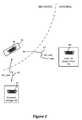
- the coil 15can also be used as a means for wirelessly receiving power from an external charger 40 , and for wirelessly receiving data from an external programmer 45 .
- These external devicesare typically separate from each other, but could be integrated as well.
- the external charger 40is typically a hand-held device used to recharge the battery 12 within the microstimulator. (In other embodiments, the external charger 40 can also be used to continuously provide energy to an implant otherwise lacking a battery).
- the external programmer 45is also typically hand held, and is used by a clinician or patient to send data to the microstimulator 10 .
- a cliniciancan provide a therapy program tailored for a particular patient, which program might specify the amplitude, pulse width, and frequency of the stimulation pulses to be provided to the patient.
- These external devicesalso contain coils 41 , 46 , which are energized to create magnetic fields, which in turn induce currents in the coil 15 within the microstimulator 10 .
- energy induced in coil 15 from coil 41is rectified and passed via charging and battery protection circuitry 14 ( FIG. 1 ) to the battery 12 , which allows the battery 12 to be safely charged to a value of about 4.1V for example.
- coil 46 in the external programmer 45is likewise energized, typically using a Frequency Shift Keying (FSK) modulation protocol.
- FSKFrequency Shift Keying
- Data telemetrycan also occur in the other direction, i.e., from the coil 15 to the coil 46 to allow the microstimulator 10 to report to the external programmer 45 concerning its status, and in this regard the telemetry circuit 16 can comprise both transmitter and receiver circuitry.
- the coil 15 in the microstimulator 10is implicated in compliance voltage generation, battery recharging, and telemetry.
- the use of one coil 15 to perform different functions in a microstimulator 10is advantageous: space is limited within the housing of the microstimulator, which tends to limits the number of discrete coils that can be used. Accordingly, it is generally necessary for the microcontroller 20 in the microstimulator 10 to arbitrate or time-multiplex the use of the coil 15 so that the various functions will not be in conflict. For example, during charging, telemetry circuitry 16 and V+ generation circuitry 18 are typically disabled by the microcontroller 20 , ensuring that the coil 15 will only be used to assist in recharging the microstimulator's battery 12 .
- the telemetry circuitry 16is enabled, and the coil 15 reserved for telemetry, during the listening window 52 .
- the duration of the listening window 52may be about 20 milliseconds (ms) or so, and ideally occurs periodically, T(t), every 100 ms or so. However, such periodicity is variable as explained below.
- Compliance voltage generationoccurs during the provision of therapeutic stimulation to a patient.
- An exemplary therapy of stimulation 60is shown in FIG. 3 .
- the stimulation 60can be understood as an alternating sequence of pulses 62 and inter-pulse periods 64 .
- the pulses 62correspond to points in time in which the desired therapeutic current, I, is provided to patient.
- Such pulses 62typically will not exceed a duration D(p) of 1 ms, and may be as low as 10 microseconds in duration.
- the inter-pulse period 64Two primary events occur during the inter-pulse period 64 after each pulse 62 .
- the compliance voltage for the next pulseis generated; this is generally necessary because the issuance of the pulse will have loaded the compliance voltage to below a level suitable for the next pulse.
- generation of the compliance voltagerequires activation of the V+ generation circuitry 18 , and access to the coil 15 .
- the decoupling capacitor 22 (C)is discharged during the inter-pulse period 64 . As disclosed in the above-incorporated U.S. Pat. No. 7,881,803, this typically occurs by coupling both the anode and the selected cathode(s) to the battery voltage, Vbat, which has the effect of shorting both sides of the decoupling capacitor 22 through the patient's tissue 24 .
- the duration, D(r), of the inter-pulse period 64is variable, and depends on the frequency, f(s), of the stimulation pulses chosen as effective for the patient.
- the inter-pulse period durationgenerally cannot be less than a certain minimum, which guarantees sufficient time to perform the necessary inter-pulse tasks of compliance voltage generation and output capacitor discharge.
- the reality of a minimum duration for the inter-pulse periodin turns limits the maximum frequency f(s) that can be chosen for the stimulation timing signal 60 , but such limit is normally beyond that required for useful therapy and hence does not substantially limit the utility of the microstimulator 10 .
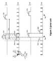
- FIG. 3Illustrated are exemplary ideal timing signals for both telemetry listening ( 50 ) and for stimulation ( 60 ).
- the listening windows 52are ideally set to a duration D(t) of 20 ms, and occur with a periodicity T(t) of 100 ms.
- the stimulation timing signal 60 in the examplehas been chosen with a pulse duration D(p) of 1 ms, and a frequency f(s) of 55.555 Hz. Working the math, this equates to an inter-pulse period duration D(r) of 17 ms, for a total stimulation period T(s) of 18 ms.
- arbitration logic 21 within the microcontroller 20will cause both the telemetry listening timing signal ( 50 ) and the stimulation timing signal ( 60 ) to deviate from ideal values. This is because the arbitration logic 21 treats each stimulation cycle 65 (comprising a pulse 62 and an inter-pulse period 64 ) and each listening window 52 as blocks that cannot overlap in time. Therefore, the microcontroller 20 , when arbitrating, will not grant priority to a listening window 52 until the currently-pending stimulation cycle 65 has completed. For example, in FIG. 3 , the ideal timing of listening window 52 a overlaps with the finishing of stimulation cycle 65 a .
- listening window 52 a ′is made to wait until the close of stimulation cycle 65 a , i.e., until the inter-pulse period 64 within that cycle has completed. Once the listening window 52 a ′ has issued, it will need unencumbered access to the coil 15 . Therefore, the next stimulation cycle 65 b ′ cannot start until the end of the listening window 52 a ′, as shown in non-ideal stimulation timing signal 60 ′.
- a non-ideal telemetry listening timing signal 50 ′ and a non-ideal stimulation timing signal 60 ′result.
- the resulting non-ideal stimulation timing signal 60 ′is potentially problematic.
- the result of the arbitration schemeresults in prolonged gaps 70 a , 70 b , etc. in the stimulation pulses 62 .
- These gaps 70 aare significantly longer (37 ms) than what was otherwise deemed as ideal therapy for the patient (17 ms), and occur with significant frequency (e.g., every sixth pulse in the example of FIG. 3 ).
- Such gross deviations from the idealmay be perceptible by the patient, and hence are greatly disfavored.
- the implantable stimulator artand particularly the microstimulator art, would benefit from an improved technique to allow concurrent stimulation and telemetry listening that does not cause large deviations of the stimulation pulses from their ideal timings.
- FIG. 1illustrates circuitry within an implantable microstimulator, and specifically shows various functional blocks (telemetry, charging, boosting) needing access to the microstimulator's singular coil.
- FIG. 2shows the microstimulator of FIG. 1 as implanted in a patient, and further shows an external charger and an external programmer in wireless communication with the microstimulator using their respective coils.
- FIG. 3illustrates ideal timing signals representing stimulation and telemetry listing, and further illustrates how those waveforms deviate from the ideal in the prior art because of arbitration schemes design to prevent concurrent use of the singular coil.
- FIGS. 4A and 4Billustrate the disclosed improved arbitration scheme, and illustrates how the improve scheme causes a smaller deviation of the stimulation pulses from their ideal timings when compared with the prior art technique of FIG. 3 .
- An improved arbitration scheme for allowing concurrent stimulation and telemetry listening in a microstimulator or other implantable pulse generatoris disclosed.
- a listening window for telemetryis permitted to proceed, and access to the microstimulator's coil granted, during at least a portion of the inter-pulse period that follows the issuance of a stimulation pulse. This is permissible because access to the coil is not needed during the entirety of the inter-pulse period.
- the listening windowcan issue during that portion of the inter-pulse period when the decoupling capacitor is discharged, because discharging of the decoupling capacitor des not require access to the coil.
- the listening windowcannot issue during that portion of the inter-pulse period when the compliance voltage is being generated for the next stimulation pulse, because compliance voltage generation does require access to the coil.
- compliance voltage generationoccurs relatively quickly and occupies only a small portion of the inter-pulse period, not being able to issue the listening window during that inter-pulse period portion does not significantly limit the technique.
- the listening windowproduces smaller gaps between the pulses. As a result, the stimulation pulses are issued at closer to their ideal positions, and the patient is less likely to perceive a difference from otherwise ideal therapy arising from the telemetry listening window.
- compliance voltage generationoccurs relatively quickly during the inter-pulse period 64 , whereas discharging of the decoupling capacitor 22 occurs relatively slowly.
- the duration of compliance voltage generation, D(g)typically occurs in under a millisecond.
- the duration necessary to discharge the decoupling capacitor, D(c)can take up to ten milliseconds or more.
- the decoupling capacitor discharge duration D(c)will be proportional to the product of the width and amplitude of the stimulation pulse, and thus will be variable, but regardless is typically at least five to ten times longer than the duration D(g) necessary for compliance voltage generation.
- the difference in these durations D(g) and D(c)is significant to the problem of interruption of the stimulation pulses 62 by the listening window 52 , especially when one considers the impact on the coil 15 .
- Decoupling capacitor dischargedoes not require coil 15 access. Therefore, the telemetry listening window 52 (where telemetry listening does require access to the coil) can be arbitrated to occur concurrently with decoupling capacitor discharge.
- compliance voltage generationdoes require access to the coil, the telemetry listening window 52 cannot be arbitrated to occur concurrently with compliance voltage generation.
- the microcontroller 20can allow the listening window 52 to issue after compliance voltage generation has finished (i.e., after duration D(g)), but concurrently with discharging of the decoupling capacitor.
- Thisis shown in the improved telemetry listening timing signal 50 ′ of FIG. 4A .
- the listening window 52 ′has been moved 53 from its ideal position ( 50 ) and into a portion of the inter-pulse period 64 such that it is issued after compliance voltage generation, D(g).
- the next stimulation pulse 62 b ′can issue after the listening window has completed. While FIG.
- arbitration in accordance with the disclosed techniquecould also move the listening window 52 ′ later in time, such that it occurs after compliance voltage generation of the next pulse 62 b , i.e., between pulses 62 b and 62 c .
- FIG. 4Bshows the resulting non-ideal stimulation timing signals 60 ′ using the prior art technique ( FIG. 3 ) and the disclosed technique ( FIG. 4A ), with listening windows 52 or 52 ′ interspersed to understand their relations to the stimulation pulses 62 .
- the disclosed techniquewhen compared to an ideal inter-pulse period D(r) of 17 ms, the disclosed technique produces a gap 70 of 21 ms (D(g)+D(t)), compared to a gap 70 of 37 ms (D(r)+D(t)).
- the resulting stimulation timing signal 60 ′is thus much closer to the ideal 60 using the disclosed technique, and accordingly is less likely to be perceived by the patient.
- the listening window 52has a relatively short duration D(t) compared to the duration D(r) of the inter-pulse period 64 in a given application
- use of the disclosed techniquecan eliminate an excessive gap 70 altogether, with the result that the resulting stimulation timing signal 60 ′ is perfectly ideal. This would occur when the sum of the duration of compliance voltage generation D(g) plus the duration of the listening window D(t) is less or equal to than the duration of the needed inter-pulse period D(r) (i.e., when D(g)+D(t) ⁇ D(r)).
- the arbitration logic 21can assess whether the microstimulator 10 is currently within an inter-pulse period 64 , and if so, whether the compliance voltage V+ has been generated to a suitable level, e.g., whether D(g) has passed, or whether a certain magnitude for V+ has been reached. If so, the arbitration logic 21 can allow the listening window 52 to issue by enabling the telemetry circuitry 16 as appropriate in accordance with the technique disclosed herein.
- the disclosed techniquecan be used to improve the timing of any sort of periodically-issued telemetry window, even if that window's purpose is not to listen for telemetry from an external device.
- time-arbitrated telemetry windowscan be used to periodically receive data from or transmit data to the external device, even while stimulation is occurring.
- programming datacould be gradually received over a number of telemetry windows while stimulation pulses are being provided to the patient.
- the microstimulatorcould use the telemetry windows to periodically provide information concerning its status to the external device, again while stimulation pulses are being provided to the patient.
Landscapes
- Health & Medical Sciences (AREA)
- Engineering & Computer Science (AREA)
- Biomedical Technology (AREA)
- Nuclear Medicine, Radiotherapy & Molecular Imaging (AREA)
- Radiology & Medical Imaging (AREA)
- Life Sciences & Earth Sciences (AREA)
- Animal Behavior & Ethology (AREA)
- General Health & Medical Sciences (AREA)
- Public Health (AREA)
- Veterinary Medicine (AREA)
- Electrotherapy Devices (AREA)
Abstract
Description
Claims (23)
Priority Applications (6)
| Application Number | Priority Date | Filing Date | Title |
|---|---|---|---|
| US11/776,170US8131377B2 (en) | 2007-07-11 | 2007-07-11 | Telemetry listening window management for an implantable medical device |
| PCT/US2008/068079WO2009009290A1 (en) | 2007-07-11 | 2008-06-25 | Telemetry listening window management for an implantable medical device |
| JP2010516122AJP5175345B2 (en) | 2007-07-11 | 2008-06-25 | Telemetry listening window management for implantable medical devices |
| ES08771858.1TES2594202T3 (en) | 2007-07-11 | 2008-06-25 | Telemetry listening window management for an implantable medical device |
| CA2687227ACA2687227C (en) | 2007-07-11 | 2008-06-25 | Telemetry listening window management for an implantable medical device |
| EP08771858.1AEP2167189B1 (en) | 2007-07-11 | 2008-06-25 | Telemetry listening window management for an implantable medical device |
Applications Claiming Priority (1)
| Application Number | Priority Date | Filing Date | Title |
|---|---|---|---|
| US11/776,170US8131377B2 (en) | 2007-07-11 | 2007-07-11 | Telemetry listening window management for an implantable medical device |
Publications (2)
| Publication Number | Publication Date |
|---|---|
| US20090018618A1 US20090018618A1 (en) | 2009-01-15 |
| US8131377B2true US8131377B2 (en) | 2012-03-06 |
Family
ID=39732811
Family Applications (1)
| Application Number | Title | Priority Date | Filing Date |
|---|---|---|---|
| US11/776,170Expired - Fee RelatedUS8131377B2 (en) | 2007-07-11 | 2007-07-11 | Telemetry listening window management for an implantable medical device |
Country Status (6)
| Country | Link |
|---|---|
| US (1) | US8131377B2 (en) |
| EP (1) | EP2167189B1 (en) |
| JP (1) | JP5175345B2 (en) |
| CA (1) | CA2687227C (en) |
| ES (1) | ES2594202T3 (en) |
| WO (1) | WO2009009290A1 (en) |
Cited By (23)
| Publication number | Priority date | Publication date | Assignee | Title |
|---|---|---|---|---|
| US8755893B2 (en) | 2010-06-08 | 2014-06-17 | Bluewind Medical Ltd. | Tibial nerve stimulation |
| US9008790B2 (en) | 2012-04-27 | 2015-04-14 | Boston Scientific Neuromodulation Corporation | Timing channel circuitry for creating pulses in an implantable stimulator device |
| US9020602B2 (en) | 2009-02-10 | 2015-04-28 | Boston Scientific Neuromodulation Corporation | External device for communicating with an implantable medical device having data telemetry and charging integrated in a single housing |
| US9174051B2 (en) | 2012-04-29 | 2015-11-03 | Boston Scientific Neuromodulation Corporation | Real time compliance voltage generation for an implantable stimulator |
| US9186504B2 (en) | 2010-11-15 | 2015-11-17 | Rainbow Medical Ltd | Sleep apnea treatment |
| US9314632B2 (en) | 2012-05-17 | 2016-04-19 | Boston Scientific Neuromodulation Corporation | Pulse-by-pulse compliance voltage generation for an implantable stimulator |
| US9358399B2 (en) | 2009-10-08 | 2016-06-07 | Boston Scientific Neuromodulation Corporation | Efficient external charger for an implantable medical device optimized for fast charging and constrained by an implant power dissipation limit |
| US9457186B2 (en) | 2010-11-15 | 2016-10-04 | Bluewind Medical Ltd. | Bilateral feedback |
| US9597521B2 (en) | 2015-01-21 | 2017-03-21 | Bluewind Medical Ltd. | Transmitting coils for neurostimulation |
| US9713707B2 (en) | 2015-11-12 | 2017-07-25 | Bluewind Medical Ltd. | Inhibition of implant migration |
| US9764146B2 (en) | 2015-01-21 | 2017-09-19 | Bluewind Medical Ltd. | Extracorporeal implant controllers |
| US9782589B2 (en) | 2015-06-10 | 2017-10-10 | Bluewind Medical Ltd. | Implantable electrostimulator for improving blood flow |
| US9861812B2 (en) | 2012-12-06 | 2018-01-09 | Blue Wind Medical Ltd. | Delivery of implantable neurostimulators |
| US10004896B2 (en) | 2015-01-21 | 2018-06-26 | Bluewind Medical Ltd. | Anchors and implant devices |
| US10105540B2 (en) | 2015-11-09 | 2018-10-23 | Bluewind Medical Ltd. | Optimization of application of current |
| US10124178B2 (en) | 2016-11-23 | 2018-11-13 | Bluewind Medical Ltd. | Implant and delivery tool therefor |
| US10653888B2 (en) | 2012-01-26 | 2020-05-19 | Bluewind Medical Ltd | Wireless neurostimulators |
| US11213685B2 (en) | 2017-06-13 | 2022-01-04 | Bluewind Medical Ltd. | Antenna configuration |
| US11400299B1 (en) | 2021-09-14 | 2022-08-02 | Rainbow Medical Ltd. | Flexible antenna for stimulator |
| US11559693B2 (en) | 2020-09-30 | 2023-01-24 | Boston Scientific Neuromodulation Corporation | Pairing of external communication devices with an implantable medical device via a patient remote controller |
| US11576223B2 (en) | 2020-09-30 | 2023-02-07 | Boston Scientific Neuromodulation Corporation | Adjustment of advertising interval in communications between an implantable medical device and an external device |
| US12005261B2 (en) | 2020-09-30 | 2024-06-11 | Boston Scientific Neuromodulation Corporation | Programming of pairing and MRI modes in an implantable medical device system |
| US12383745B2 (en) | 2019-09-06 | 2025-08-12 | Boston Scientific Neuromodulation Corporation | Management of compliance voltage for a stimulator device |
Families Citing this family (12)
| Publication number | Priority date | Publication date | Assignee | Title |
|---|---|---|---|---|
| US9233254B2 (en)* | 2009-02-17 | 2016-01-12 | Boston Scientific Neuromodulation Corporation | Selectable boost converter and charge pump for compliance voltage generation in an implantable stimulator device |
| WO2011097289A1 (en) | 2010-02-03 | 2011-08-11 | Medtronic, Inc. | Implantable medical devices and systems having dual frequency inductive telemetry and recharge |
| US9042995B2 (en)* | 2010-02-03 | 2015-05-26 | Medtronic, Inc. | Implantable medical devices and systems having power management for recharge sessions |
| US9136728B2 (en) | 2011-04-28 | 2015-09-15 | Medtronic, Inc. | Implantable medical devices and systems having inductive telemetry and recharge on a single coil |
| US20130123881A1 (en)* | 2011-11-11 | 2013-05-16 | Boston Scientific Neuromodulation Corporation | External Charger for an Implantable Medical Device System Having a Coil for Communication and Charging |
| US9795788B2 (en)* | 2013-05-30 | 2017-10-24 | Pacesetter, Inc. | Implantable medical devices, and methods of use therewith, that use a same coil for receiving both communication and power signals |
| WO2015023359A1 (en)* | 2013-08-14 | 2015-02-19 | Boston Scientific Neuromodulation Corporation | Power architecture for an implantable medical device having a non-rechargeable battery |
| EP3903876B1 (en) | 2013-09-16 | 2024-10-23 | The Board of Trustees of the Leland Stanford Junior University | Multi-element coupler for generation of electromagnetic energy |
| US20160336813A1 (en) | 2015-05-15 | 2016-11-17 | NeuSpera Medical Inc. | Midfield coupler |
| EP3294173B1 (en) | 2014-05-18 | 2020-07-15 | Neuspera Medical Inc. | Midfield coupler |
| CA3040164A1 (en)* | 2016-10-16 | 2018-04-19 | Stimaire, Inc. | Wireless neural stimulator with injectable |
| CN118217536B (en)* | 2024-05-27 | 2024-08-09 | 苏州新云医疗设备有限公司 | Implantable neurostimulator and system |
Citations (27)
| Publication number | Priority date | Publication date | Assignee | Title |
|---|---|---|---|---|
| US5088488A (en) | 1989-12-22 | 1992-02-18 | Medtronic, Inc. | Method and apparatus for implementing histogram storage and trend analysis in a medical stimulator |
| US5201865A (en) | 1991-10-28 | 1993-04-13 | Medtronic, Inc. | Medical lead impedance measurement system |
| US5309919A (en) | 1992-03-02 | 1994-05-10 | Siemens Pacesetter, Inc. | Method and system for recording, reporting, and displaying the distribution of pacing events over time and for using same to optimize programming |
| US5314458A (en) | 1990-06-01 | 1994-05-24 | University Of Michigan | Single channel microstimulator |
| US5507786A (en) | 1994-04-14 | 1996-04-16 | Pacesetter, Inc. | System and method for measuring and storing parametric data pertaining to operating characteristics of an implantable medical device |
| US5733312A (en) | 1997-01-17 | 1998-03-31 | Pacesetter, Inc. | System and method for modulating the output of an implantable medical device in response to circadian variations |
| US5766232A (en) | 1996-05-10 | 1998-06-16 | Medtronic, Inc. | Method and apparatus for altering the Q of an implantable medical device telemetry antenna |
| US20020045920A1 (en) | 2000-08-26 | 2002-04-18 | Medtronic, Inc. | Implanted medical device telemetry using integrated thin film bulk acoustic resonator filtering |
| US6516227B1 (en) | 1999-07-27 | 2003-02-04 | Advanced Bionics Corporation | Rechargeable spinal cord stimulator system |
| US6535766B1 (en) | 2000-08-26 | 2003-03-18 | Medtronic, Inc. | Implanted medical device telemetry using integrated microelectromechanical filtering |
| US20030074036A1 (en) | 1998-02-06 | 2003-04-17 | Intermedics Inc. | Implantable device with digital waveform telemetry |
| US6553263B1 (en) | 1999-07-30 | 2003-04-22 | Advanced Bionics Corporation | Implantable pulse generators using rechargeable zero-volt technology lithium-ion batteries |
| US6556871B2 (en) | 2001-01-04 | 2003-04-29 | Cardiac Pacemakers, Inc. | System and method for receiving telemetry data from an implantable medical device |
| US20040015205A1 (en) | 2002-06-20 | 2004-01-22 | Whitehurst Todd K. | Implantable microstimulators with programmable multielectrode configuration and uses thereof |
| US20040059392A1 (en) | 2002-06-28 | 2004-03-25 | Jordi Parramon | Microstimulator having self-contained power source |
| US20050131496A1 (en) | 2000-03-17 | 2005-06-16 | Jordi Parramon | Voltage converter for implantable microstimulator using RF-powering coil |
| US20050131495A1 (en) | 2002-06-28 | 2005-06-16 | Jordi Parramon | Systems and methods for providing power to a battery in an implantable stimulator |
| US20050277844A1 (en) | 2004-06-10 | 2005-12-15 | Ndi Medical, Inc. | Implantable system and methods for acquisition and processing of electrical signals from muscles and/or nerves and/or central nervous system tissue |
| WO2005123184A2 (en) | 2004-06-10 | 2005-12-29 | Ndi Medical, Llc | System and method for treating incontinence with implantation in adipose tissue |
| US20060276842A1 (en) | 2005-06-01 | 2006-12-07 | Advanced Bionics Corporation | Implantable microstimulator with external electrodes disposed on a film substrate and methods of manufacture and use |
| US20070060980A1 (en) | 2004-06-10 | 2007-03-15 | Ndi Medical, Llc | Implantable pulse generator systems and methods for providing functional and/or therapeutic stimulation of muscles and/or nerves and/or central nervous system tissue |
| US20070088398A1 (en) | 2005-10-14 | 2007-04-19 | Jacobson Peter M | Leadless cardiac pacemaker triggered by conductive communication |
| US20070112404A1 (en) | 2005-11-16 | 2007-05-17 | Mann Alfred E | Implantable stimulator |
| US20070161919A1 (en) | 1998-08-05 | 2007-07-12 | Bioneuronics Corporation | Methods and systems for continuous EEG monitoring |
| US20070167997A1 (en) | 2003-10-02 | 2007-07-19 | Medtronic, Inc. | Method of Energy Transfer to an Implantable Medical Device While Coupling Energy to Charging Unit |
| US20070270921A1 (en) | 2006-05-17 | 2007-11-22 | Ndi Medical, Inc. | Systems and methods for patient control of stimulation systems |
| WO2007136657A2 (en) | 2006-05-17 | 2007-11-29 | Ndi Medical, Inc. | Implantable pulse generator systems and methods for providing stimulation |
- 2007
- 2007-07-11USUS11/776,170patent/US8131377B2/ennot_activeExpired - Fee Related
- 2008
- 2008-06-25ESES08771858.1Tpatent/ES2594202T3/enactiveActive
- 2008-06-25EPEP08771858.1Apatent/EP2167189B1/ennot_activeNot-in-force
- 2008-06-25JPJP2010516122Apatent/JP5175345B2/ennot_activeExpired - Fee Related
- 2008-06-25WOPCT/US2008/068079patent/WO2009009290A1/enactiveApplication Filing
- 2008-06-25CACA2687227Apatent/CA2687227C/ennot_activeExpired - Fee Related
Patent Citations (39)
| Publication number | Priority date | Publication date | Assignee | Title |
|---|---|---|---|---|
| US5088488A (en) | 1989-12-22 | 1992-02-18 | Medtronic, Inc. | Method and apparatus for implementing histogram storage and trend analysis in a medical stimulator |
| US5314458A (en) | 1990-06-01 | 1994-05-24 | University Of Michigan | Single channel microstimulator |
| US5201865A (en) | 1991-10-28 | 1993-04-13 | Medtronic, Inc. | Medical lead impedance measurement system |
| US5309919A (en) | 1992-03-02 | 1994-05-10 | Siemens Pacesetter, Inc. | Method and system for recording, reporting, and displaying the distribution of pacing events over time and for using same to optimize programming |
| US5507786A (en) | 1994-04-14 | 1996-04-16 | Pacesetter, Inc. | System and method for measuring and storing parametric data pertaining to operating characteristics of an implantable medical device |
| US5766232A (en) | 1996-05-10 | 1998-06-16 | Medtronic, Inc. | Method and apparatus for altering the Q of an implantable medical device telemetry antenna |
| US5733312A (en) | 1997-01-17 | 1998-03-31 | Pacesetter, Inc. | System and method for modulating the output of an implantable medical device in response to circadian variations |
| US20030074036A1 (en) | 1998-02-06 | 2003-04-17 | Intermedics Inc. | Implantable device with digital waveform telemetry |
| US20070161919A1 (en) | 1998-08-05 | 2007-07-12 | Bioneuronics Corporation | Methods and systems for continuous EEG monitoring |
| US6516227B1 (en) | 1999-07-27 | 2003-02-04 | Advanced Bionics Corporation | Rechargeable spinal cord stimulator system |
| US6553263B1 (en) | 1999-07-30 | 2003-04-22 | Advanced Bionics Corporation | Implantable pulse generators using rechargeable zero-volt technology lithium-ion batteries |
| US20050131496A1 (en) | 2000-03-17 | 2005-06-16 | Jordi Parramon | Voltage converter for implantable microstimulator using RF-powering coil |
| US6535766B1 (en) | 2000-08-26 | 2003-03-18 | Medtronic, Inc. | Implanted medical device telemetry using integrated microelectromechanical filtering |
| US6868288B2 (en) | 2000-08-26 | 2005-03-15 | Medtronic, Inc. | Implanted medical device telemetry using integrated thin film bulk acoustic resonator filtering |
| US20020045920A1 (en) | 2000-08-26 | 2002-04-18 | Medtronic, Inc. | Implanted medical device telemetry using integrated thin film bulk acoustic resonator filtering |
| US6556871B2 (en) | 2001-01-04 | 2003-04-29 | Cardiac Pacemakers, Inc. | System and method for receiving telemetry data from an implantable medical device |
| US20030199939A1 (en) | 2001-01-04 | 2003-10-23 | Cardiac Pacemakers, Inc. | System and method for receiving telemetry data from an implantable medical device |
| US20070135865A1 (en) | 2001-01-04 | 2007-06-14 | Cardiac Pacemakers, Inc. | System and method for receiving telemetry data from an implantable medical device |
| US20040015205A1 (en) | 2002-06-20 | 2004-01-22 | Whitehurst Todd K. | Implantable microstimulators with programmable multielectrode configuration and uses thereof |
| US20050131495A1 (en) | 2002-06-28 | 2005-06-16 | Jordi Parramon | Systems and methods for providing power to a battery in an implantable stimulator |
| US7120992B2 (en) | 2002-06-28 | 2006-10-17 | Advanced Bionics Corporation | Method of making an electronic module |
| US20040059392A1 (en) | 2002-06-28 | 2004-03-25 | Jordi Parramon | Microstimulator having self-contained power source |
| US7177698B2 (en) | 2002-06-28 | 2007-02-13 | Advanced Bionics Corporation | Telemetry system for use with microstimulator |
| US20070167997A1 (en) | 2003-10-02 | 2007-07-19 | Medtronic, Inc. | Method of Energy Transfer to an Implantable Medical Device While Coupling Energy to Charging Unit |
| US20070060967A1 (en) | 2004-06-10 | 2007-03-15 | Ndi Medical, Llc | Implantable pulse generator systems and methods for providing functional and /or therapeutic stimulation of muscles and/or nerves and/or central nervous system tissue |
| US20050277844A1 (en) | 2004-06-10 | 2005-12-15 | Ndi Medical, Inc. | Implantable system and methods for acquisition and processing of electrical signals from muscles and/or nerves and/or central nervous system tissue |
| US20050278000A1 (en) | 2004-06-10 | 2005-12-15 | Strother Robert B | Implantable pulse generator for providing functional and/or therapeutic stimulation of muscles and/or nerves and/or central nervous system tissue |
| WO2005123185A1 (en) | 2004-06-10 | 2005-12-29 | Ndi Medical, Llc | Implantable system for processing myoelectric signals |
| US20050277999A1 (en) | 2004-06-10 | 2005-12-15 | Ndi Medical, Llc | Implantable pulse generator for providing functional and/or therapeutic stimulation of muscles and /or nerves and/or central nervous system tissue |
| US20070060980A1 (en) | 2004-06-10 | 2007-03-15 | Ndi Medical, Llc | Implantable pulse generator systems and methods for providing functional and/or therapeutic stimulation of muscles and/or nerves and/or central nervous system tissue |
| WO2005123181A2 (en) | 2004-06-10 | 2005-12-29 | Ndi Medical, Llc | Implantable pulse generator for providing functional and/or therapeutic stimulation of muscles and/or nerves and/or central nervous system tissue |
| WO2005123184A2 (en) | 2004-06-10 | 2005-12-29 | Ndi Medical, Llc | System and method for treating incontinence with implantation in adipose tissue |
| US20060276842A1 (en) | 2005-06-01 | 2006-12-07 | Advanced Bionics Corporation | Implantable microstimulator with external electrodes disposed on a film substrate and methods of manufacture and use |
| WO2007047681A2 (en) | 2005-10-14 | 2007-04-26 | Nanostim, Inc. | Leadless cardiac pacemaker and system |
| US20070088398A1 (en) | 2005-10-14 | 2007-04-19 | Jacobson Peter M | Leadless cardiac pacemaker triggered by conductive communication |
| US20070112404A1 (en) | 2005-11-16 | 2007-05-17 | Mann Alfred E | Implantable stimulator |
| US20070112403A1 (en) | 2005-11-16 | 2007-05-17 | Moffitt Michael A | Electrode contact configurations for an implantable stimulator |
| US20070270921A1 (en) | 2006-05-17 | 2007-11-22 | Ndi Medical, Inc. | Systems and methods for patient control of stimulation systems |
| WO2007136657A2 (en) | 2006-05-17 | 2007-11-29 | Ndi Medical, Inc. | Implantable pulse generator systems and methods for providing stimulation |
Non-Patent Citations (4)
| Title |
|---|
| International Preliminary Report on Patentability regarding corresponding PCT application No. PCT/US2008/068079, dated Jan. 21, 2010. |
| International Search Report and Written Opinion received in corresponding application No. PCT/US2008/068079 dated Oct. 2, 2008. |
| Rodriguez et al.; "Flexible Communication and Control Protocol for Injectable Neuromuscular Interfaces;" IEEE Transactions on Biomedical Circuits and Systems; vol. 1 No. 1; Mar. 2007; pp. 19-27. |
| U.S. Appl. No. 11/550,655, filed Oct. 18, 2006, Parramon. |
Cited By (48)
| Publication number | Priority date | Publication date | Assignee | Title |
|---|---|---|---|---|
| US9020602B2 (en) | 2009-02-10 | 2015-04-28 | Boston Scientific Neuromodulation Corporation | External device for communicating with an implantable medical device having data telemetry and charging integrated in a single housing |
| US9867995B2 (en) | 2009-10-08 | 2018-01-16 | Boston Scientific Neuromodulation Corporation | Efficient external charger for an implantable medical device optimized for fast charging and constrained by an implant power dissipation limit |
| US9358399B2 (en) | 2009-10-08 | 2016-06-07 | Boston Scientific Neuromodulation Corporation | Efficient external charger for an implantable medical device optimized for fast charging and constrained by an implant power dissipation limit |
| US8755893B2 (en) | 2010-06-08 | 2014-06-17 | Bluewind Medical Ltd. | Tibial nerve stimulation |
| US8788045B2 (en) | 2010-06-08 | 2014-07-22 | Bluewind Medical Ltd. | Tibial nerve stimulation |
| US9186504B2 (en) | 2010-11-15 | 2015-11-17 | Rainbow Medical Ltd | Sleep apnea treatment |
| US9457186B2 (en) | 2010-11-15 | 2016-10-04 | Bluewind Medical Ltd. | Bilateral feedback |
| US10653888B2 (en) | 2012-01-26 | 2020-05-19 | Bluewind Medical Ltd | Wireless neurostimulators |
| US11648410B2 (en) | 2012-01-26 | 2023-05-16 | Bluewind Medical Ltd. | Wireless neurostimulators |
| US12059571B2 (en) | 2012-01-26 | 2024-08-13 | Bluewind Medical Ltd | Wireless neurostimulators |
| US9144687B2 (en) | 2012-04-27 | 2015-09-29 | Boston Scientific Neuromodulation Corporation | Timing channel circuitry for creating pulses in an implantable stimulator device |
| US9008790B2 (en) | 2012-04-27 | 2015-04-14 | Boston Scientific Neuromodulation Corporation | Timing channel circuitry for creating pulses in an implantable stimulator device |
| US9468771B2 (en) | 2012-04-27 | 2016-10-18 | Boston Scientific Neuromodulation Corporation | Timing channel circuitry for creating pulses in an implantable stimulator device |
| US10391322B2 (en) | 2012-04-27 | 2019-08-27 | Boston Scientific Neuromodulation Corporation | Timing channel circuitry for creating pulses in an implantable stimulator device |
| US9925385B2 (en) | 2012-04-27 | 2018-03-27 | Boston Scientific Neuromodulation Corporation | Timing channel circuitry for creating pulses in an implantable stimulator device |
| US9174051B2 (en) | 2012-04-29 | 2015-11-03 | Boston Scientific Neuromodulation Corporation | Real time compliance voltage generation for an implantable stimulator |
| US9314632B2 (en) | 2012-05-17 | 2016-04-19 | Boston Scientific Neuromodulation Corporation | Pulse-by-pulse compliance voltage generation for an implantable stimulator |
| US10363423B2 (en) | 2012-05-17 | 2019-07-30 | Boston Scientific Neuromodulation Corporation | Pulse-by-pulse compliance voltage generation for an implantable stimulator |
| US9757565B2 (en) | 2012-05-17 | 2017-09-12 | Boston Scientific Neuromodulation Corporation | Pulse-by-pulse compliance voltage generation for an implantable stimulator |
| US11464966B2 (en) | 2012-12-06 | 2022-10-11 | Bluewind Medical Ltd. | Delivery of implantable neurostimulators |
| US11278719B2 (en) | 2012-12-06 | 2022-03-22 | Bluewind Medical Ltd. | Delivery of implantable neurostimulators |
| US9861812B2 (en) | 2012-12-06 | 2018-01-09 | Blue Wind Medical Ltd. | Delivery of implantable neurostimulators |
| US10238863B2 (en) | 2012-12-06 | 2019-03-26 | Bluewind Medical Ltd. | Delivery of implantable neurostimulators |
| US9597521B2 (en) | 2015-01-21 | 2017-03-21 | Bluewind Medical Ltd. | Transmitting coils for neurostimulation |
| US9764146B2 (en) | 2015-01-21 | 2017-09-19 | Bluewind Medical Ltd. | Extracorporeal implant controllers |
| US10004896B2 (en) | 2015-01-21 | 2018-06-26 | Bluewind Medical Ltd. | Anchors and implant devices |
| US10369366B2 (en) | 2015-06-10 | 2019-08-06 | Bluewind Medical Ltd. | Implantable electrostimulator for improving blood flow |
| US9782589B2 (en) | 2015-06-10 | 2017-10-10 | Bluewind Medical Ltd. | Implantable electrostimulator for improving blood flow |
| US10105540B2 (en) | 2015-11-09 | 2018-10-23 | Bluewind Medical Ltd. | Optimization of application of current |
| US11612747B2 (en) | 2015-11-09 | 2023-03-28 | Bluewind Medical Ltd. | Optimization of application of current |
| US11116975B2 (en) | 2015-11-09 | 2021-09-14 | Bluewind Medical Ltd. | Optimization of application of current |
| US9713707B2 (en) | 2015-11-12 | 2017-07-25 | Bluewind Medical Ltd. | Inhibition of implant migration |
| US10449374B2 (en) | 2015-11-12 | 2019-10-22 | Bluewind Medical Ltd. | Inhibition of implant migration |
| US11439833B2 (en) | 2016-11-23 | 2022-09-13 | Bluewind Medical Ltd. | Implant-delivery tool |
| US10124178B2 (en) | 2016-11-23 | 2018-11-13 | Bluewind Medical Ltd. | Implant and delivery tool therefor |
| US10744331B2 (en) | 2016-11-23 | 2020-08-18 | Bluewind Medical Ltd. | Implant and delivery tool therefor |
| US11951316B2 (en) | 2017-06-13 | 2024-04-09 | Bluewind Medical Ltd. | Antenna configuration |
| US11213685B2 (en) | 2017-06-13 | 2022-01-04 | Bluewind Medical Ltd. | Antenna configuration |
| US12383745B2 (en) | 2019-09-06 | 2025-08-12 | Boston Scientific Neuromodulation Corporation | Management of compliance voltage for a stimulator device |
| US11833357B2 (en) | 2020-09-30 | 2023-12-05 | Boston Scientific Neuromodulation Corporation | Pairing of external communication devices with an implantable medical device via a patient remote controller |
| US11818782B2 (en) | 2020-09-30 | 2023-11-14 | Boston Scientific Neuromodulation Corporation | Adjustment of advertising interval in communications between an implantable medical device and an external device |
| US12005261B2 (en) | 2020-09-30 | 2024-06-11 | Boston Scientific Neuromodulation Corporation | Programming of pairing and MRI modes in an implantable medical device system |
| US11576223B2 (en) | 2020-09-30 | 2023-02-07 | Boston Scientific Neuromodulation Corporation | Adjustment of advertising interval in communications between an implantable medical device and an external device |
| US12101835B2 (en) | 2020-09-30 | 2024-09-24 | Boston Scientific Neuromodulation Corporation | Adjustment of advertising interval in communications between an implantable medical device and an external device |
| US12138462B2 (en) | 2020-09-30 | 2024-11-12 | Boston Scientific Neuromodulation Corporation | Pairing of external communication devices with an implantable medical device via a patient remote controller |
| US11559693B2 (en) | 2020-09-30 | 2023-01-24 | Boston Scientific Neuromodulation Corporation | Pairing of external communication devices with an implantable medical device via a patient remote controller |
| US12427325B2 (en) | 2020-09-30 | 2025-09-30 | Boston Scientific Neuromodulation Corporation | Programming of pairing and MRI modes in an implantable medical device system |
| US11400299B1 (en) | 2021-09-14 | 2022-08-02 | Rainbow Medical Ltd. | Flexible antenna for stimulator |
Also Published As
| Publication number | Publication date |
|---|---|
| CA2687227A1 (en) | 2009-01-15 |
| CA2687227C (en) | 2014-04-15 |
| US20090018618A1 (en) | 2009-01-15 |
| ES2594202T3 (en) | 2016-12-16 |
| JP5175345B2 (en) | 2013-04-03 |
| WO2009009290A1 (en) | 2009-01-15 |
| JP2010532700A (en) | 2010-10-14 |
| EP2167189B1 (en) | 2016-07-20 |
| EP2167189A1 (en) | 2010-03-31 |
Similar Documents
| Publication | Publication Date | Title |
|---|---|---|
| US8131377B2 (en) | Telemetry listening window management for an implantable medical device | |
| US10518089B2 (en) | Reversing recruitment order by anode intensification | |
| US9913987B2 (en) | Spatially selective nerve stimulation in high-frequency nerve conduction block and recruitment | |
| US9339655B2 (en) | System and method for compounding low-frequency sources for high-frequency neuromodulation | |
| US10118040B2 (en) | Neuromodulation using modulated pulse train | |
| US9694183B2 (en) | Neuromodulation system and method for providing multiple modulation patterns in a single channel | |
| US9981134B2 (en) | Multi-channel neuromodulation system having frequency modulation stimulation | |
| EP2958619B1 (en) | Neurostimulation system having increased flexibility for creating complex pulse trains | |
| US8812128B2 (en) | Implantable neurostimulator-initiated status notification | |
| EP2190527A1 (en) | Use of stimulation pulse shape to control neural recruitment order and clinical effect | |
| US20140031908A1 (en) | System and method for enhancing large diameter nerve fiber stimulation using sequential activation of electrodes |
Legal Events
| Date | Code | Title | Description |
|---|---|---|---|
| AS | Assignment | Owner name:ADVANCED BIONICS CORPORATION, CALIFORNIA Free format text:ASSIGNMENT OF ASSIGNORS INTEREST;ASSIGNORS:SHI, JESS W.;PARRAMON, JORDI;REEL/FRAME:019601/0127 Effective date:20070709 | |
| AS | Assignment | Owner name:BOSTON SCIENTIFIC NEUROMODULATION CORPORATION, CAL Free format text:CHANGE OF NAME;ASSIGNOR:ADVANCED BIONICS CORPORATION;REEL/FRAME:020405/0722 Effective date:20071116 Owner name:BOSTON SCIENTIFIC NEUROMODULATION CORPORATION,CALI Free format text:CHANGE OF NAME;ASSIGNOR:ADVANCED BIONICS CORPORATION;REEL/FRAME:020405/0722 Effective date:20071116 | |
| ZAAA | Notice of allowance and fees due | Free format text:ORIGINAL CODE: NOA | |
| ZAAB | Notice of allowance mailed | Free format text:ORIGINAL CODE: MN/=. | |
| FEPP | Fee payment procedure | Free format text:PAYOR NUMBER ASSIGNED (ORIGINAL EVENT CODE: ASPN); ENTITY STATUS OF PATENT OWNER: LARGE ENTITY | |
| STCF | Information on status: patent grant | Free format text:PATENTED CASE | |
| FPAY | Fee payment | Year of fee payment:4 | |
| MAFP | Maintenance fee payment | Free format text:PAYMENT OF MAINTENANCE FEE, 8TH YEAR, LARGE ENTITY (ORIGINAL EVENT CODE: M1552); ENTITY STATUS OF PATENT OWNER: LARGE ENTITY Year of fee payment:8 | |
| FEPP | Fee payment procedure | Free format text:MAINTENANCE FEE REMINDER MAILED (ORIGINAL EVENT CODE: REM.); ENTITY STATUS OF PATENT OWNER: LARGE ENTITY | |
| LAPS | Lapse for failure to pay maintenance fees | Free format text:PATENT EXPIRED FOR FAILURE TO PAY MAINTENANCE FEES (ORIGINAL EVENT CODE: EXP.); ENTITY STATUS OF PATENT OWNER: LARGE ENTITY | |
| STCH | Information on status: patent discontinuation | Free format text:PATENT EXPIRED DUE TO NONPAYMENT OF MAINTENANCE FEES UNDER 37 CFR 1.362 | |
| FP | Lapsed due to failure to pay maintenance fee | Effective date:20240306 |