US8131049B2 - Breast tomosynthesis with display of highlighted suspected calcifications - Google Patents
Breast tomosynthesis with display of highlighted suspected calcificationsDownload PDFInfo
- Publication number
- US8131049B2 US8131049B2US12/605,031US60503109AUS8131049B2US 8131049 B2US8131049 B2US 8131049B2US 60503109 AUS60503109 AUS 60503109AUS 8131049 B2US8131049 B2US 8131049B2
- Authority
- US
- United States
- Prior art keywords
- images
- breast
- pixels
- displaying
- suspected
- Prior art date
- Legal status (The legal status is an assumption and is not a legal conclusion. Google has not performed a legal analysis and makes no representation as to the accuracy of the status listed.)
- Active, expires
Links
Images


Classifications
- G—PHYSICS
- G06—COMPUTING OR CALCULATING; COUNTING
- G06T—IMAGE DATA PROCESSING OR GENERATION, IN GENERAL
- G06T7/00—Image analysis
- G06T7/0002—Inspection of images, e.g. flaw detection
- G06T7/0012—Biomedical image inspection
- A—HUMAN NECESSITIES
- A61—MEDICAL OR VETERINARY SCIENCE; HYGIENE
- A61B—DIAGNOSIS; SURGERY; IDENTIFICATION
- A61B6/00—Apparatus or devices for radiation diagnosis; Apparatus or devices for radiation diagnosis combined with radiation therapy equipment
- A61B6/02—Arrangements for diagnosis sequentially in different planes; Stereoscopic radiation diagnosis
- A61B6/025—Tomosynthesis
- A—HUMAN NECESSITIES
- A61—MEDICAL OR VETERINARY SCIENCE; HYGIENE
- A61B—DIAGNOSIS; SURGERY; IDENTIFICATION
- A61B6/00—Apparatus or devices for radiation diagnosis; Apparatus or devices for radiation diagnosis combined with radiation therapy equipment
- A61B6/12—Arrangements for detecting or locating foreign bodies
- A—HUMAN NECESSITIES
- A61—MEDICAL OR VETERINARY SCIENCE; HYGIENE
- A61B—DIAGNOSIS; SURGERY; IDENTIFICATION
- A61B6/00—Apparatus or devices for radiation diagnosis; Apparatus or devices for radiation diagnosis combined with radiation therapy equipment
- A61B6/46—Arrangements for interfacing with the operator or the patient
- A61B6/461—Displaying means of special interest
- A—HUMAN NECESSITIES
- A61—MEDICAL OR VETERINARY SCIENCE; HYGIENE
- A61B—DIAGNOSIS; SURGERY; IDENTIFICATION
- A61B6/00—Apparatus or devices for radiation diagnosis; Apparatus or devices for radiation diagnosis combined with radiation therapy equipment
- A61B6/50—Apparatus or devices for radiation diagnosis; Apparatus or devices for radiation diagnosis combined with radiation therapy equipment specially adapted for specific body parts; specially adapted for specific clinical applications
- A61B6/502—Apparatus or devices for radiation diagnosis; Apparatus or devices for radiation diagnosis combined with radiation therapy equipment specially adapted for specific body parts; specially adapted for specific clinical applications for diagnosis of breast, i.e. mammography
- A—HUMAN NECESSITIES
- A61—MEDICAL OR VETERINARY SCIENCE; HYGIENE
- A61B—DIAGNOSIS; SURGERY; IDENTIFICATION
- A61B6/00—Apparatus or devices for radiation diagnosis; Apparatus or devices for radiation diagnosis combined with radiation therapy equipment
- A61B6/52—Devices using data or image processing specially adapted for radiation diagnosis
- A61B6/5211—Devices using data or image processing specially adapted for radiation diagnosis involving processing of medical diagnostic data
- G—PHYSICS
- G06—COMPUTING OR CALCULATING; COUNTING
- G06V—IMAGE OR VIDEO RECOGNITION OR UNDERSTANDING
- G06V10/00—Arrangements for image or video recognition or understanding
- G06V10/40—Extraction of image or video features
- G06V10/44—Local feature extraction by analysis of parts of the pattern, e.g. by detecting edges, contours, loops, corners, strokes or intersections; Connectivity analysis, e.g. of connected components
- G06V10/457—Local feature extraction by analysis of parts of the pattern, e.g. by detecting edges, contours, loops, corners, strokes or intersections; Connectivity analysis, e.g. of connected components by analysing connectivity, e.g. edge linking, connected component analysis or slices
- G—PHYSICS
- G16—INFORMATION AND COMMUNICATION TECHNOLOGY [ICT] SPECIALLY ADAPTED FOR SPECIFIC APPLICATION FIELDS
- G16H—HEALTHCARE INFORMATICS, i.e. INFORMATION AND COMMUNICATION TECHNOLOGY [ICT] SPECIALLY ADAPTED FOR THE HANDLING OR PROCESSING OF MEDICAL OR HEALTHCARE DATA
- G16H50/00—ICT specially adapted for medical diagnosis, medical simulation or medical data mining; ICT specially adapted for detecting, monitoring or modelling epidemics or pandemics
- G16H50/20—ICT specially adapted for medical diagnosis, medical simulation or medical data mining; ICT specially adapted for detecting, monitoring or modelling epidemics or pandemics for computer-aided diagnosis, e.g. based on medical expert systems
- A—HUMAN NECESSITIES
- A61—MEDICAL OR VETERINARY SCIENCE; HYGIENE
- A61B—DIAGNOSIS; SURGERY; IDENTIFICATION
- A61B6/00—Apparatus or devices for radiation diagnosis; Apparatus or devices for radiation diagnosis combined with radiation therapy equipment
- A61B6/52—Devices using data or image processing specially adapted for radiation diagnosis
- A61B6/5211—Devices using data or image processing specially adapted for radiation diagnosis involving processing of medical diagnostic data
- A61B6/5223—Devices using data or image processing specially adapted for radiation diagnosis involving processing of medical diagnostic data generating planar views from image data, e.g. extracting a coronal view from a 3D image
- A—HUMAN NECESSITIES
- A61—MEDICAL OR VETERINARY SCIENCE; HYGIENE
- A61B—DIAGNOSIS; SURGERY; IDENTIFICATION
- A61B6/00—Apparatus or devices for radiation diagnosis; Apparatus or devices for radiation diagnosis combined with radiation therapy equipment
- A61B6/52—Devices using data or image processing specially adapted for radiation diagnosis
- A61B6/5211—Devices using data or image processing specially adapted for radiation diagnosis involving processing of medical diagnostic data
- A61B6/5252—Devices using data or image processing specially adapted for radiation diagnosis involving processing of medical diagnostic data removing objects from field of view, e.g. removing patient table from a CT image
- G—PHYSICS
- G06—COMPUTING OR CALCULATING; COUNTING
- G06T—IMAGE DATA PROCESSING OR GENERATION, IN GENERAL
- G06T2207/00—Indexing scheme for image analysis or image enhancement
- G06T2207/10—Image acquisition modality
- G06T2207/10072—Tomographic images
- G06T2207/10081—Computed x-ray tomography [CT]
- G—PHYSICS
- G06—COMPUTING OR CALCULATING; COUNTING
- G06T—IMAGE DATA PROCESSING OR GENERATION, IN GENERAL
- G06T2207/00—Indexing scheme for image analysis or image enhancement
- G06T2207/30—Subject of image; Context of image processing
- G06T2207/30004—Biomedical image processing
- G06T2207/30068—Mammography; Breast
- G—PHYSICS
- G06—COMPUTING OR CALCULATING; COUNTING
- G06V—IMAGE OR VIDEO RECOGNITION OR UNDERSTANDING
- G06V2201/00—Indexing scheme relating to image or video recognition or understanding
- G06V2201/03—Recognition of patterns in medical or anatomical images
- G06V2201/032—Recognition of patterns in medical or anatomical images of protuberances, polyps nodules, etc.
Definitions
- This patent specificationpertains to x-ray tomosynthesis, and more specifically to techniques and equipment for acquiring, processing, storing and displaying tomosynthesis images, including tomosynthesis projection images and tomosynthesis reconstructed images.
- An important aspect of this patent specificationpertains to identifying and highlighting suspected calcifications in displays of tomosynthesis images.
- X-ray mammographyremains a well-established technology, and x-ray tomosynthesis of the breast has been developed recently as discussed in the earlier-filed patent applications identified above.
- Clinical testing of tomosynthesis systemshas been carried out, and the assignee of this patent specification, Hologic, Inc., has demonstrated at trade shows in this country a fused, multimode mammography/tomosynthesis system that takes either or both types of images, either in single or multiple compressions/immobilizations of the breast.
- Dedicated breast tomosynthesis systemsalso have been proposed.
- Tomosynthesis as used in the systems and methods disclosed in this patent specificationtypically involves acquiring a plurality of tomosynthesis projection images Tp at respective angles relative to the breast, and using information describing at least these images Tp (or some of the Tp images) to reconstruct a plurality of tomosynthesis reconstructed images Tr representative of respective breast slices that have selective thicknesses and orientations and correspond to respective sections through or slices of the breast that typically are but need not be planar.
- the slicescan be curved in 3D space.
- conventional x-ray mammography images Mpcan be acquired, in the same procedure that acquires the Tp images of a breast or in a different procedure and in the same or different compressions of the breast, and may be used in addition to the Tp images or in place of some of the Tp images, in reconstructing Tr images.
- Mp imagescan be processed by various techniques that draw attention to selected portions or features of these images, such as CAD (computer aided detection) techniques that analyze the images to identify likely abnormalities and place markers on a breast image or representation that identify the location and in some cases the type or other information about the likely abnormalities.
- CADcomputer aided detection
- Some of the parent applications identified abovedescribe applying CAD analysis to Tr and/or Tp images as well, or as an alternative or an adjunct to applying CAD to Mp images, and also describe how to improve the presentations of Tp and/or Tr images (collectively referred to here as T images), Mp images, and CAD and/or other information about the images to make the review by health professionals more effective and efficient.
- CAD application to Mp imagesalso is a well-established technology. See, for example, the mammography CAD products offered by R2 Technology, Inc. of Sunnyvale, Calif. and Patent Publications US 2002/0097902 and US 2004/0100476 and U.S. Pat. Nos. 5,970,164, and 6,630,937.
- U.S. Pat. No. 6,748,044discusses applying CAD to tomosynthesis images and U.S. Pat. No. 7,149,335 discusses detecting microcalcifications in tomosynthesis images and subtracting background to enhance visibility of the detected microcalcifications.
- Also possibly relevant to state-of-the-artmay be US20030194121A1, U.S. Pat. No. 6,748,044, US20030215120A1, US20050002550A1, US20060269114A1, US20050089205A1, US20050113961A1, U.S. Pat. No. 7,142,633, US20060067473A1, US20060210131A1, US20070003117A1, US20070003118A1, US20070014448A1, US20070052700A1, US20070076928A1.
- the patents and publication identified in this paragraphalso are incorporated by reference in this patent specification.
- the notation Mprefers to a conventional mammogram, which is a two-dimensional x-ray projection image of a breast; the term Mp encompasses both a digital image as acquired by a flat panel detector or another imaging device and the image after conventional processing to prepare it for display to a health professional or for further processing or for storage, e.g. in the PACS system of a hospital or another institution. Mp also encompasses digitized film/screen mammograms.
- Trrefers to an image that is similarly two-dimensional but is taken at a respective tomosynthesis angle between the breast and the origin of the imaging X-rays (typically the focal spot of an X-ray tube), and also encompasses the image as acquired as well as the image after being processed for display or for some other use.
- Trrefers to an image that is reconstructed from images Tp, for example in the manner described in said earlier-filed patent applications, and represents a slice of the breast essentially as it would appear in a projection X-ray image of that slice at any desired angle, not only at an angle used for Tp or Mp images.
- a Tr imagecan represent a slice that conforms to any desired surface such as a flat or curved plane.
- Tr imagescan use Mp images in addition to using Tp images or instead of one or more Tp images.
- Tp, Tr and Mpalso encompasses information, in whatever form, that is sufficient to describe such an image for display, further processing, or storage.
- the images Mp, Tp and Trtypically are in digital form before being displayed, and can be defined by information identifying properties of each pixel in a two-dimensional array of pixels, although other ways to describe the images can be used as well or instead.
- the pixel valuestypically relate to respective measured or estimated or computed responses to X-rays of corresponding volumes in the breast (voxels or columns of tissue).
- a Tr imagecan represents a thin slice of a breast, in which case it may consist of pixel values representing respective voxels (volume elements) of the breast that are in a single layer or a few layers transverse to the direction of the x-ray beam, or a Tr image may represent a thicker slice of the breast, in which case the pixel values of the thick-slice Tr image can represent columns of tissue along the direction of the x-ray beam and are calculated using known techniques such as, without limitation, a normalized projection of the pixels of several contiguous thin-slice images onto an image plane, a MW (maximum intensity projection), or some other way of combining the pixel values representing several thin-slice images.
- a thin-slice Tr imagecan represent a 1 mm thick slice of the imaged breast and a thick-slice Tr image can represent a 5-20 mm thick slice of the breast.
- a thin-slice Tr imagecan represent a 1 mm thick slice of the imaged breast and a thick-slice Tr image can represent a 5-20 mm thick slice of the breast.
- Microcalcifications seen in breast imagesare considered important clues in screening and/or diagnosis, and prior proposals have been directed to identifying particular specific patterns of microcalcifications or all microcalcifications, or at least those having specified characteristics such as size or density.
- This patent specificationtakes a different approach by not only necessarily seeking to identify and classify patterns of microcalcification distributions in images, or to identify or enhance all microcalcifications detectable in the image, but rather to facilitate the visualization of up to a certain number of selected suspected calcifications that meet various special thresholds in a given image or volume of tissue in ways that are particularly useful to the health professional.
- Calcificationsoften have a typical x-ray absorption characteristic, but not all objects with these absorption characteristics are calcifications or are of clinical value.
- Calcifications of clinical interestgenerally fall in a certain range of sizes and shapes and patterns.
- the largest calcificationsare often benign. Linear ones also are often benign. Identifying all of the very smallest calcification-like objects runs the risk that some of them might represent noise and not true calcifications or reasonably suspected calcifications.
- One object of the approach disclosed in this patent specificationis to reduce the number of identified possible or suspected calcifications which are of lower clinical value.
- the approach disclosed in this patent specificationinvolves examining through computer processing the individual Tr images in a 3D set of such images to identify an initial set of possible calcifications that meets a threshold limiting the number of identified calcifications in a given Tr image, or in the entire 3D set or a selected subset of the entire 3D set, to a specified number of calcifications and/or number of pixels that are determined to correspond to calcifications.
- the Tr imagesare presented for this examination after filtering with a mask that enhances high spatial frequency image features.
- the processremoves from the initial set, pixels initially determined to relate to calcifications that are too large in area or too long in linear extent, and may additionally impose other constraints such as excluding initially determined calcifications that are not present in two adjacent Tr images, applying ligament removal and edge removal techniques, requiring at least a certain number of calcifications to be in a specified volume of the 3D set, and excluding calcifications that are in the initial and trailing Tr images in a stack of Tr images and thus are likely to be at the skin level and unlikely to have clinical significance.
- the removal processesare designed to remove calcifications that are likely to be devoid of clinical interest and to remove noise and other non-calcification objects.
- one exampleis to show a scout view that generally conforms in shape to a projection of the breast and shows a distribution of identified calcifications as well as a current level that both (1) includes calcifications and (2) corresponds to a Tr image that is orthogonal to the scout image and is seen at a main image display.
- this informationcan be displayed using a ruler or other schematic display that does not conform in shape to a projection of the breast but still allows display of the current level and/or the locations of likely calcifications.
- the current level in the 2D scout or schematic viewpoints to one or more corresponding Tr images.
- the scout or schematic viewalso shows a pointer to a next level that contains identified calcifications so that a user can conveniently click on that level and thus call on the main display the next Tr image of interest.
- the scout or schematic viewmay also indicate how many calcification clusters are in a given Tr image.
- the usercan toggle the main display between showing a Tr image with or without highlighted calcifications therein.
- a health professionalthus can quickly and effectively review Tr images that are likely to be of interest.
- the health professionalcan additionally select for the main display additional Tr images, Tr images that are for thick or thin slices and/or reconstructed in another orientation, Tp images and/or Mp images.
- An alternative or additional processis to initially search Tp and/or Mp images rather than the 3D set of Tr images to identify likely calcifications of interest. This can be done using CAD as disclosed in the patent literature incorporated by reference in this patent specification, or by adapting the principles discussed above for identifying calcifications in Tr images and 3D volumes, or in some other manner. After likely calcifications of clinical significance are identified in the 2D Tp and/or Mp images, the 2D images can be displayed one at a time or several at a time, or only those 2D images that have identified calcifications can be displayed.
- Tr images of the breastcan be searched through the Tr images of the breast to identify and display the Tr image or Tr images that contain that calcification.
- This search through the Tr imagescan use knowledge about the location of the likely calcification in the 2D image, on parameters of the calcification such as its size, shape, pixel values and distribution of those values in the 2D image, and possibly other parameters.
- Tr imagesIn case of an ambiguity, i.e., the calcification pointed to in the 2D image appears in two or more Tr images, all possibly relevant Tr images can be displayed to the user, singly or in a set or subsets or in cine mode, and the user may select for further use the ones that appear relevant or dismiss any that are not.
- This alternativecan reduce processing time because the search for likely calcifications in the 2D images can be faster, and the subsequent search for the Tr slice(s) that contain a calcification to which the user pointed in a 2D image also can be faster.
- One reason for greater computational efficiencyis that the 3D data set (the Tr images) need to be processed only after a likely calcification has been selected, so only a relatively small volume of the 3D set would need to be searched.
- Another advantage of this alternativemay be if the search process is more sensitive and/or more accurate for 2D images. If so, then it is more likely to decrease the overall rate of false negatives and/or false positives in identifying likely calcifications, and thus improve the presentation of images to the health professional and make the overall process of assessing the images for screening, diagnosis, or other purposes, more effective and/or more efficient.
- the usercan point to any feature in one of the 2D images, not necessarily a likely calcification, even in 2D images that have not been processed to identify likely calcifications, and the process can attempt to identify and display for the user the Tr slice(s) in which that feature can be seen well, e.g., the feature is in best focus.
- the search through the 3D set of pixel datacan use information about the feature to which the user pointed, such as location in the 2D image, size, shape, pixel values and distribution of those values, and possibly other parameters. If the feature is relatively unique and small, the process may correctly identify and display for the user one or only a few Tr slices.
- the processmay similarly display the possibly pertinent Tr slices, or may display only those that meet a threshold of relevance, e.g., based on a calculation of their degree of relevance to the feature to which the user pointed.
- FIG. 1illustrates an example of a display of a scout image and a reconstructed tomosynthesis slice image Tr.
- FIG. 2illustrates in block diagram form a mammography/tomosynthesis system that can be used to acquire breast imaging x-ray data and process and display the data according to preferred embodiments of the approach disclosed in this patent specification.
- FIG. 3is a flowchart illustrating an embodiment of a new process.
- FIG. 4illustrates a method of displaying a current slice and locations of calcifications.
- FIG. 5illustrates a method of identifying calcifications on a tomosynthesis slice image Tr.
- the image on the leftis a scout view 10 that generally conforms to an outline of a patient's breast and contains bright dots indicative of calcifications identified through a process described below.
- Two facing arrows 12 a and 12 b at the side of scout image 10point to a level in the scout image that corresponds to a reconstructed tomosynthesis slice image Tr 12 seen at the right side of FIG. 1 .
- the views of images 10 and 12are mutually orthogonal. Tr image 12 in this example has highlighted calcifications (seen as white dots) that are more numerous than those seen in scout image 10 , for reasons that will become apparent from the disclosure below.
- Tr image 12can be displayed without highlighting its suspected calcifications, as a normal Tr image, by a user command such as clicking a mouse button or through some other interface.
- the Tr image that is displayed as image 12can be for a thin slice, e.g., a 1 mm or somewhat thinner or thicker slice of breast tissue, or for a thick slice such as a 3 mm or somewhat thinner or thicker slice of breast tissue, in which case the thick-slice image can be formed by combining several thin slice Tr image through a known process such as, without limitation, adding with or without normalization, MIP projection, etc.
- data representing Tp imagescan be reconstructed into data representing thick-slice Tr images in the reconstruction process using known techniques such as using appropriate backprojection or frequency domain filters.
- the usercan click on button 13 a , 13 b and 13 c to toggle display 12 between a Tr image with and without highlighted suspected calcification, or to the previous and next Tr images.
- FIG. 4shows an alternative method to the scout view for identifying slice locations for calcifications. This involves a ruler that indicates both the currently-displayed slice, in terms of its height or position in a stack of Tr images and corresponding slices of breast tissue (using a marker such as the one labeled “Slice position indicator” in FIG. 4 ), and also Calcification slice indicator marks that show the slices where potential calcifications have been identified (by marks such as the arrows labeled “Calcification slice indicator” in FIG. 4 ).
- FIG. 5shows an alternative method for identifying calcifications that does not require highlighting them.
- potential calcificationsare outlined by a box such as the one labeled “Square indicating calcifications” in FIG. 5 .
- Arrows pointing to the calcificationswould be an alternative method, as would other marks and or lines and or color and/or intensity changes on the image in the vicinity of the calcifications.
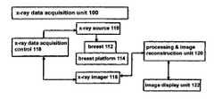
- an x-ray data acquisition unit 100includes an x-ray source 110 imaging a patient's breast 112 supported on a breast platform 114 .
- An x-ray imager 116such as a flat panel, direct conversion imager available from Hologic, Inc. of Bedford, Mass., generates projection image data such as data defining images Mp and/or Tp.
- X-ray source 110is mounted for movement around breast platform 114 so that images Tp (and Mp, if desired) can be taken at a number of different angles for a specific orientation of breast platform 114 , such as a generally CC orientation or a generally MLO orientation.
- X-ray imager 116can be stationary but preferably it also moves relative to breast platform 114 , in a specified synchronous relationship to source 110 , preferably in a manner that keeps the imaging plane at the same angle to the imaging x-ray beam.
- Units 110 and 116communicate with x-ray data acquisition control 118 that controls the operation of the system as known from said material incorporated by reference.
- X-ray data from imager 116is delivered to processing and image reconstruction unit 120 that includes one or more programmed digital computers, where data is processed as known into Tp and possibly Mp images and into Tr images and where the process described below is carried out.
- the resulting informationis displayed at image display unit 122 .
- the software for any specific implementation of specific data processing hardwarecan be written without undue experimentation by a person skilled in the art based on the disclosure of this patent specification. The details of such implementation would depend to a certain extent on factors such as the hardware and operating systems that a particular designer or user would select, and many variations are possible. For the sake of both clarity and conciseness such details that are within the skill of the art once the disclosure herein is available, are not included in this patent specification.
- the processing carried out by unit 120typically includes known filtering and preliminary processing of the Tp image data (and any Mp data used in addition to or instead of Tp image data) and reconstruction of thin and/or thick slice Tr image data that defines a 3D set of pixel values.
- the 3D setis made up of the pixel values representing an x-ray property of respective pixels of each of a number of Tr images, each Tr image representing a respective slice of breast tissue.
- the Tr images used in steps 1-4 belowrepresent thin slices of the breast, such as 1 mm slices, but using thicker slice images is not excluded.
- These pixel valuesare processed in the following principal steps as a non-limiting preferred example following a filtering of the Tr images individually to suppress low spatial frequency components. Any one of a number of known filtering processes can be used, such as a process involving the use of unsharp mask filters.
- FIG. 3illustrates a particular implementation of a process related to the above-described example.
- the process of FIG. 3starts with inputting data describing the reconstructed images Tr for a given view, e.g., the Tr images reconstructed from the Tp images taken when the breast is imaged in a position suitable for a CC or an MLO view.
- the numbered steps discussed belowcorrespond to the blocks of FIG. 3 .
- the input Tr imagesare reconstructed images representing breast tissue slices, where the pixel values outside the breast area are constant (i.e., the image has been masked by previous processing).
- global parametersare defined, and adjusted for pixel size, and memory is allocated to process the given Mammographic View; which in this case is a Tr image.
- a global thresholdis defined using a specified slice, for example, the center slice in the stack (View) as follows.
- the resultant thresholdis used for all subsequent slices. Note that the method for calculating threshold can also be used for each slice separately.
- the candidate image K iis ‘slabbed’ (as a non-limiting example, added on a per pixel basis) with adjacent slices to give binary Slab image S i .
- the slabbingis per pixel and uses 3 contiguous slices.
- a running summay be used for efficiency if the Tr slice images are input consecutively.
- the first slice of the previous slabis subtracted and the current slice is added to the slab image.
- S iis then Re-labeled to give new label image M i .
- N g⁇ k (f ⁇ 1, if V j >V j+k 0, if V j ⁇ V j+k ⁇
- Regroup the valid labels in the volumesuch that labeled pixels that are within ⁇ 10 mm in x,y, and ⁇ 5 mm in z, are in the same group. This connects groups that may exist over several slices and may contain a slice with no labeled pixels. This step combines the previous per slice groups that may overlap (or be close) in the volume.
- SOI'sare those slices which may be used in the Viewing application that will allow the user to quickly scroll the TCE identified slices within a View.
- a SOIis defined for each identified group as the slice that contains the most labeled pixels in that group. Note that 2 different groups may have the same SOI.
- Some other possible methodsinclude:
- An alternative or additional processinvolves finding likely calcification in the individual 2D Tp and/or Mp images and then searching only subsets of the 3D Tr images to select corresponding Tr images for selective display to the user. This can be implemented by initially searching Tp and/or Mp images rather than the 3D set of Tr images to identify likely calcifications of interest.
- the initial search of 2D imagescan be done using CAD as disclosed in the patent literature incorporated by reference in this patent specification, or by adapting the principles discussed above for identifying calcifications in Tr images and 3D volumes, or in some other manner.
- the 2D imagescan be displayed one at a time or several at a time, or only those 2D images that have identified calcifications can be displayed.
- computer processingcan search through the Tr images of the breast to identify and display the Tr image or Tr images that contain that calcification. This search through the Tr images can use knowledge about the location of the likely calcification in the 2D image, on parameters of the calcification such as its size, shape, pixel values and distribution of those values in the 2D image, and possibly other parameters.
- Tr imagesIn case of an ambiguity, i.e., the calcification pointed to in the 2D image appears in two or more Tr images, all possibly relevant Tr images can be displayed to the user, singly or in a set or subsets or in cine mode, and the user may select for further use the ones that appear relevant or dismiss any that are not.
- This alternativecan reduce processing time because the search for likely calcifications in the 2D images can be faster, and the subsequent search for the Tr slice(s) that contain a calcification to which the user pointed in a 2D image also can be faster.
- One reason for greater computational efficiencyis that the 3D data set (the Tr images) need to be processed only after a likely calcification has been selected, so only a relatively small volume of the 3D set would need to be searched.
- Another advantage of this alternativemay be if the search process is more sensitive and/or more accurate for 2D images. If so, then it is more likely to decrease the overall rate of false negatives and/or false positives in identifying likely calcifications, and thus improve the presentation of images to the health professional and make the overall process of assessing the images for screening, diagnosis, or other purposes, more effective anti/or more efficient.
- the usercan point to any feature in one of the 2D images, not necessarily a likely calcification, even in 2D images that have not been processed to identify likely calcifications, and the process can attempt to identify and display for the user the Tr slice(s) in which that feature can be seen well, e.g., the feature is in best focus.
- the search through the 3D set of pixel datacan use information about the feature to which the user pointed, such as location in the 2D image, size, shape, pixel values and distribution of those values, and possibly other parameters. If the feature is relatively unique and small, the process may correctly identify and display for the user one or only a few Tr slices.
- the processmay similarly display the possibly pertinent Tr slices, or may display only those that meet a threshold of relevance, e.g., based on a calculation of their degree of relevance to the feature to which the user pointed.
Landscapes
- Engineering & Computer Science (AREA)
- Health & Medical Sciences (AREA)
- Life Sciences & Earth Sciences (AREA)
- Medical Informatics (AREA)
- Physics & Mathematics (AREA)
- General Health & Medical Sciences (AREA)
- Radiology & Medical Imaging (AREA)
- Nuclear Medicine, Radiotherapy & Molecular Imaging (AREA)
- Public Health (AREA)
- Biomedical Technology (AREA)
- Pathology (AREA)
- Veterinary Medicine (AREA)
- Biophysics (AREA)
- Optics & Photonics (AREA)
- Heart & Thoracic Surgery (AREA)
- Molecular Biology (AREA)
- Surgery (AREA)
- Animal Behavior & Ethology (AREA)
- High Energy & Nuclear Physics (AREA)
- Computer Vision & Pattern Recognition (AREA)
- General Physics & Mathematics (AREA)
- Theoretical Computer Science (AREA)
- Quality & Reliability (AREA)
- Multimedia (AREA)
- Dentistry (AREA)
- Oral & Maxillofacial Surgery (AREA)
- Human Computer Interaction (AREA)
- Data Mining & Analysis (AREA)
- Databases & Information Systems (AREA)
- Epidemiology (AREA)
- Primary Health Care (AREA)
- Apparatus For Radiation Diagnosis (AREA)
Abstract
Description
- 1. Compute and use a threshold to form a first provisional set of pixels that are candidates for inclusion in a final set of pixels that are determined to be associated with calcifications and called “calc pixels” below. The objective is to include in the final set of calc pixels no more than a selected number N of pixels for the entire 3D set of pixels defining the Tr images. For example, candidate calc pixels can be identified in this step by provisionally identifying as calc pixels the pixels that have pixel values exceeding a provisional threshold level. This can be done by processing only the pixel values in one or several Tr images that may correspond to centrally located breast tissue, or it can be done for the entire 3D set. As a non-limiting example, if pixel values in a particular system are adjusted to range from −60 to +60 units in value in a Tr image after filtering per step 1 above, any pixel that has a value greater than, e.g., 40 can be provisionally classified as a calc pixel in a first iteration. If the total number of candidate calc pixels found in the Tr image in the first iteration is too large (as a non-limiting example, more than 150) then the provisional threshold of 40 is raised, e.g., to 41, and the process is repeated to provisionally classify as candidate calc pixel those having pixel values greater than 41. If the initial iteration yields a total number of calc pixels that is too low (as a non-limiting example, less than 50) the initial threshold is lowered, e.g., to 39, and the process is repeated. These iterations are repeated until the total number of candidate calc pixels is in the desired range, for example and without limitation, in the range of 50 to 150 calc pixels for the given Tr image. The specific initial threshold, the size of the steps by which it is raised or lowered, and the desired range of total number of candidate calc pixels can be set depending on user preferences, either as part of the design process or as a parameter that can be set by service personnel or by the user of the system in the field, or on the basis of a study of typical values for a large population of breast images. This step yields a first provisional set of calc pixels.
- 2. Form a second provisional set of candidate pixels by excluding those associated with large areas in a Tr image that contain contiguous, i.e., connected, or nearly contiguous candidate calc pixels. As a non-limiting example, exclude from the first provisional set the candidate calc pixels associated with areas greater than 0.31 square mm (e.g. an area of about 30 pixels). The test can be for an area of only contiguous pixels provisionally identified as calc pixels, or it can be for areas in which any provisionally identified calc pixel is spaced by no more than one (or a set multiple of) pixels that are not calc pixels. This removes calcifications that would be clearly visible, or of little clinical relevance, in a Tr image so there is no need to point them out to the health professional and, moreover, if left in the displayed images they might obscure other, smaller calcification that should be pointed out.
- 3. Form a third provisional set of calc pixels by removing from the second provisional set the pixels that are generally arranged in lines that have excessive lengths. These linear groups of candidate calc pixels may be associated with blood vessels or other structures that may be of less interest than other calcifications. For example, a line of contiguous or nearly contiguous candidate calc pixels that is more than 2-4 mm long may be considered too long in this step. The term nearly contiguous is used in this patent specification to denote calc pixels that might be separated by one (or a set multiple of) non-calc pixels.
- 4. Form a fourth provisional set of calc pixels by removing from the third set the candidate calc pixels that do not have as contiguous neighbors, candidate calc pixels in at least two adjacent Tr images, as they are likely to be image noise.
- 5. Combine the thin-slice Tr images that still have candidate calc pixels into thick-slice Tr images to facilitate volume analysis. As a non-limiting example, add and if desired normalize, each set of three contiguous Tr images into a respective thick-slice Tr image by forming a new pixel by adding the values of three contiguous pixels in a direction transverse to the planes of the Tr images and dividing the result by three. As an alternative, combine into a thick-slice Tr image the several Tr images that contain candidate calc pixels forming in 3D a clump of candidate calc pixels, e.g., a 3D clump of candidate calc pixels that have at least a specified density (ratio of all pixels to candidate calc pixels, or the reverse).
- 6. Form a fifth set of candidate calc pixels by removing from the fourth set the candidate calc pixels that are arranged in lines that are too long in any direction (e.g. more than 2-4 mm) in a thick-slice Tr image and, therefore, are likely to be associated with structures such as ligaments, blood vessels, or cyst walls.
- 7. Form a sixth set of candidate calc pixels by eliminating from the fifth set the candidate calc pixels that are not in a set of at least a specified number of candidate calc pixels in a specified volume of the 3D set of pixels, e.g., in a volume that represents a 1 cm by 1 cm by 3 mm volume of the breast, where the 3 mm is the size of the thick slice Tr image.
- 8. Form a seventh set of candidate calc pixels by eliminating from the sixth set the candidate calc pixels that are too low in density in the 3D volume of pixels. For example, eliminate candidate calc pixels that are in a volume of the 3D set of pixels of a specified size in which there is too low a ratio of (a) total number of calc pixels in the volume to (b) the number of candidate calcs, where a candidate calc consists of connected calc pixels. As a non-limiting example, a ratio less than 1.1 in a volume of 1 cm by 1 cm by 3 mm can be considered too low. This step tends to eliminate candidate calcs that may represent image noise.
- 9. Form a final set of calc pixels by eliminating from the seventh set the candidate calc pixels that are in the first and last set of Tr images, as they are likely to correspond to pixels related to breast skin. As a non-limiting example, the candidate calc pixels from the first and last 1-3 Tr images in a stack of Tr images may be eliminated in this step.
- 10. Project the final set of calc pixels onto an image plane that is orthogonal to the planes of the Tr images to thereby form a scout image such as
image 10 inFIG. 1 . If desired, enhance the projected calc pixels so that they would stand out better inimage 10. For example, increase the pixel values of the calc pixels in the final set to a higher value so that they appear as brighter spots in the scout image and/or increase the sizes of spots in the scout image that represent determined calcifications by setting to a higher or highest pixel value the pixels that are within a specified distance from a calc pixel that is in the final set. - 11. Provide user interface and interaction between arrows in the
scout images 10 andTr images 12 for display as inFIG. 1 , for example by including indisplay unit 122 appropriate user interface devices such as a mouse or other pointer to enable the user to click on selected arrows inimage 10 and to make the system respond to the clicks as described above[c1]. - 12. Selectively enhance calcifications in
images 12, by increasing their brightness and/or size, comparable to the enhancement of thescout image 10 described in step 11 above. - 13. Provide for user interaction in selecting display of
images 12 with or without such enhancement by higher brightness of pixels representing calcifications inimages 12, for example by including indisplay unit 122 appropriate user interface devices such as a mouse or other pointer to enable the user to click onimage 12 or some other display portion to toggle between a Tr image with or without enhanced calcifications and/or to toggle between the display of a thin-slice Tr image and the display of a thick-slice Tr image. For example, a thin-slice Tr image can represent a 1 mm thick slice of breast tissue while a thick-slice Tr image can represent a 3 mm or thicker slice of breast tissue[c2]. - 14. Provide for user interaction in selecting display of
images 12 with or without such enhancement by higher brightness of pixels representing calcifications inimages 12, by slabbing a given number of slices to form a thick slice. In slabbing, the calc pixels may be slabbed independently of the image pixels that are not identified as calc pixels. The term “slabbing” is used here in the sense of “combining” or “integrating” parameters of the pixels of images representing thinner slices into pixels of an image representing a thicker slice. Various known slabbing techniques can be used such as averaging with or without normality after, median, mode, maximum, MIP and/or other operations for collapsing columns of pixels. - 15. Provide for user interaction in selecting display of
images 12 with or without such enhancement by higher brightness of pixels representing calcifications inimages 12, by slabbing calc pixels belonging to an identified cluster, where the slabbed calc pixels are shown on a specified slice. The image pixels that are not calc pixels, in those slices that contain calc pixels, may or may not be slabbed.
- 1. From input slice image Oi, where the subscript refers to the slice number, create smooth slice image, Siusing a 5×5 boxcar filter)
- 2. Create Unsharp mask image Ui=Oi−Si, where the typical range of values in Uiis −60 to +60
- 3. Threshold images Uiwith fixed initial threshold of 40 to produce binary image Bi
- Bi=0 if Ui<40
- Bi=1 if Ui>=40
- 4. Label pixels in Bito produce Label image Li(the label image assigns a unique label to any connected positive value pixels in B)
- 5. Calculate label density as follows
Labdense=(Nlab/bfrac) - bfrac=# of pixels in breast/total number of pixels
- Nlab=number of labels
- Check if Labdense is within a specified fixed range and adjust the threshold if needed as follows. If Labdense<LabdenseMin, lower the threshold by 1.0 If Labdense>=LabdenseMax, raise the threshold by 1.0
- Where LabdenseMin=1000 and LabdenseMaz=2500
- 1. Pixel Population Cut
- Delete labels that have more than Nmax pixels where
- Nmax=MaxPixArea/PixSize2
- PixSize=size of pixels in mm
- MaxPixArea=0.3 mm2
- Delete labels that have more than Nmax pixels where
- 2. Range Cut
- a. Calculate the linear extent of labels in x and y
- b. Delete labels that have an extent (in either direction) larger than 0.63 mm
- 3. Boundary Cut
- a. Delete labels that are close to the breast boundary. Currently, if a label pixel is within 3 mm of the skin edge, it is deleted.
- 1. Pixel Population Cut
Ki=Li&& Li-1
Ng=Σk(f×{1, if Vj>Vj+k0, if Vj≦Vj+k}
- where k={−2,2,2*Nx,−2*Nx,1−Nx,−1−Nx,1+Nx,Nx−1}
- f=1.04
- Nx=number of columns in the image.
- if Ng<8, unset Label pixel j in M.
- 1. Search for peaks in pixel intensity along x direction starting with candidate labeled pixel as center. The search distance is ±0.8 mm from the center labeled pixel. Extract a line L of pixel values along the x-dimension with the center point being a calc pixel. The length of L is 1 mm.
- 2. Calculate the peak (maximum value) and maximum derivative value, Li−Li-1, of L.
- 3. If peak is above a threshold (=30), count as valid peak.
- 4. Repeat steps 2-4 for pixel centers located at ±N (perpendicular to line L) from the calc pixel, where N=0.8 mm/(pixel size). Sum the number of valid peaks and calculate the average maximum derivative.
- 5. If number of valid peaks is above the maximum (=1.6 mm/(pixel size)−1) unset the calc Label pixel in M
- 6. If average maximum derivative is above a threshold (=150), unset calc Label pixel in M.
- 7. Repeat steps 1-7 searching along the y direction instead of x. The lines L being along the y-direction.
- 8. Repeat steps 1-8 for all labeled pixels.
- 1. Search neighborhood (±5 mm) and sum all Labels. If sum is greater than 2, assign a group label, otherwise unset Label. This keeps all clusters of 3 calcs within a 1 mm square.
- 1. Calculate Calc Pixel Density, CPD
CPD=(Number of pixels in group)÷(Number of labels (calcs) in group) - 2. If CPD≧CPDmin(=3), do not apply any additional cuts, and do not delete the group.
- 3. If CPD<CPDminapply the following cuts in order.
- 3.1 If CPD<1.1, delete group. Otherwise proceed with Cut 3.2
- 3.2 Calculate Δnn
Δnn=Ave(C)−Ave(N) - Ave(C)=average pixel value of labels in the group.
- Ave(N)=average pixel value of neighboring pixels (nearest neighbors of C)
- 1. Calculate Calc Pixel Density, CPD
- If (Δnn<25) delete group
- If (Δnn<42 && CPD<1.7) delete group
- 3.3 Fit a 3rdorder polynomial to the distribution of labels within the group. If the x-extent of the group is greater than the y-extent, x is the dependent variable, otherwise y is the dependent variable. Calculate the normalized chi-squared of the fit,
Nchi=chi-squared÷Number of points used in lit - If Nchi<0.10 delete group
- 3.3 Fit a 3rdorder polynomial to the distribution of labels within the group. If the x-extent of the group is greater than the y-extent, x is the dependent variable, otherwise y is the dependent variable. Calculate the normalized chi-squared of the fit,
- 1. Finding calcifications using the Tp data, and identifying the calcification locations on the Tr dataset for display, as described.
- 2. Finding calcifications using both the Tp and the Tr data, and identifying the calcification locations on the Tr dataset for display as described. Using both Tp and Tr may improve the accuracy or computational efficiency of the calc determination algorithm[c3]. Methods for identifying calcifications in Tp are known, such as shown in the material incorporated by reference herein. Once potential calcifications in Tp are found, their possible locations in Tr can be determined through reconstruction of the locations found in the Tp images, such as described in the material incorporated by reference herein.
- 3. A similar method can be used to identify possible pathology masses, and lesions containing both masses and calcs. Methods of identifying possible pathology masses are given in the material, herein incorporated by reference. An inventive feature here is the user interface whereby only slices are shown that have either masses or calcs or both. The CAD algorithm can use either Tr or Tp or both datasets to do its determination.
- 4. In the above-described approach, the display of a given slice might contain calcifications (or masses) from other slices, especially if they have been ascertained to be part of the same cluster. If desired, a different highlighting can be applied to calcs or masses that also are present in adjacent Tr slices that are not displayed at the moment.
- 5. Instead of displaying only breast slice images that include pixels determined to be calcifications, display all breast slice images or at least a subset of all breast slice images, including some that do not have such pixels, such that the user can scroll through those images. The user can be helped to identify the calc pixels, particularly if their brightness is enhanced as discussed above, by the sudden change in brightness in scrolling from one displayed slice image to the next or help can be provided by marking the calc, e.g. with some symbol. Then change from one slice image to another can be directed manually by the user, or the display can be automated to present the succession of slice images in cine format.
- 6. Instead of or in addition to identifying talcs, the process can be adapted to identify masses using for example CAD techniques such as those described in the material incorporated in this patent specification by reference. Suspected abnormalities can then be selectively specified to be (1) only calcifications, (2) only masses, and (3) both calcifications and masses. The selection and display of masses can then be similar to the selection and display of calcifications described above.
- 7. Instead of the process described above to identify abnormalities corresponding to suspected calcifications, a simpler process can be used such as a filter that identifies all pixels in a Tp and/or Tr image that meet specified threshold criteria of pixel values selected to identify pixels likely to correspond to calcifications. Known techniques can be used to eliminate from an initial cut those abnormalities that are likely to represent noise, such as isolated single pixels that meet the threshold criteria or very small groups of such pixels. The remaining suspected abnormalities can then be displayed as described above.
Claims (47)
Priority Applications (4)
| Application Number | Priority Date | Filing Date | Title |
|---|---|---|---|
| US12/605,031US8131049B2 (en) | 2007-09-20 | 2009-10-23 | Breast tomosynthesis with display of highlighted suspected calcifications |
| US13/358,913US8571292B2 (en) | 2007-09-20 | 2012-01-26 | Breast tomosynthesis with display of highlighted suspected calcifications |
| US14/064,319US8873824B2 (en) | 2007-09-20 | 2013-10-28 | Breast tomosynthesis with display of highlighted suspected calcifications |
| US14/500,434US9202275B2 (en) | 2007-09-20 | 2014-09-29 | Breast tomosynthesis with display of highlighted suspected calcifications |
Applications Claiming Priority (2)
| Application Number | Priority Date | Filing Date | Title |
|---|---|---|---|
| US11/903,021US7630533B2 (en) | 2007-09-20 | 2007-09-20 | Breast tomosynthesis with display of highlighted suspected calcifications |
| US12/605,031US8131049B2 (en) | 2007-09-20 | 2009-10-23 | Breast tomosynthesis with display of highlighted suspected calcifications |
Related Parent Applications (1)
| Application Number | Title | Priority Date | Filing Date |
|---|---|---|---|
| US11/903,021ContinuationUS7630533B2 (en) | 2007-09-20 | 2007-09-20 | Breast tomosynthesis with display of highlighted suspected calcifications |
Related Child Applications (1)
| Application Number | Title | Priority Date | Filing Date |
|---|---|---|---|
| US13/358,913ContinuationUS8571292B2 (en) | 2007-09-20 | 2012-01-26 | Breast tomosynthesis with display of highlighted suspected calcifications |
Publications (2)
| Publication Number | Publication Date |
|---|---|
| US20100086188A1 US20100086188A1 (en) | 2010-04-08 |
| US8131049B2true US8131049B2 (en) | 2012-03-06 |
Family
ID=40468718
Family Applications (5)
| Application Number | Title | Priority Date | Filing Date |
|---|---|---|---|
| US11/903,021Active2027-12-31US7630533B2 (en) | 2007-09-20 | 2007-09-20 | Breast tomosynthesis with display of highlighted suspected calcifications |
| US12/605,031Active2028-02-09US8131049B2 (en) | 2007-09-20 | 2009-10-23 | Breast tomosynthesis with display of highlighted suspected calcifications |
| US13/358,913ActiveUS8571292B2 (en) | 2007-09-20 | 2012-01-26 | Breast tomosynthesis with display of highlighted suspected calcifications |
| US14/064,319ActiveUS8873824B2 (en) | 2007-09-20 | 2013-10-28 | Breast tomosynthesis with display of highlighted suspected calcifications |
| US14/500,434ActiveUS9202275B2 (en) | 2007-09-20 | 2014-09-29 | Breast tomosynthesis with display of highlighted suspected calcifications |
Family Applications Before (1)
| Application Number | Title | Priority Date | Filing Date |
|---|---|---|---|
| US11/903,021Active2027-12-31US7630533B2 (en) | 2007-09-20 | 2007-09-20 | Breast tomosynthesis with display of highlighted suspected calcifications |
Family Applications After (3)
| Application Number | Title | Priority Date | Filing Date |
|---|---|---|---|
| US13/358,913ActiveUS8571292B2 (en) | 2007-09-20 | 2012-01-26 | Breast tomosynthesis with display of highlighted suspected calcifications |
| US14/064,319ActiveUS8873824B2 (en) | 2007-09-20 | 2013-10-28 | Breast tomosynthesis with display of highlighted suspected calcifications |
| US14/500,434ActiveUS9202275B2 (en) | 2007-09-20 | 2014-09-29 | Breast tomosynthesis with display of highlighted suspected calcifications |
Country Status (3)
| Country | Link |
|---|---|
| US (5) | US7630533B2 (en) |
| EP (2) | EP2201493B1 (en) |
| WO (1) | WO2009038948A2 (en) |
Cited By (19)
| Publication number | Priority date | Publication date | Assignee | Title |
|---|---|---|---|---|
| US20090185733A1 (en)* | 2007-11-23 | 2009-07-23 | General Electric Company | Method and Apparatus for Processing Digital Mammographic Images |
| US20120121159A1 (en)* | 2010-11-10 | 2012-05-17 | Hernandez-Cisneros Rolando-Rafael | Method for the detection and classification of microcalcification clusters in digital mammograms |
| US20120121155A1 (en)* | 2007-09-20 | 2012-05-17 | Hologic, Inc. | Breast tomosynthesis with display of highlighted suspected calcifications |
| US9066706B2 (en) | 2004-11-26 | 2015-06-30 | Hologic, Inc. | Integrated multi-mode mammography/tomosynthesis x-ray system and method |
| US9460508B2 (en) | 2002-11-27 | 2016-10-04 | Hologic, Inc. | Image handling and display in X-ray mammography and tomosynthesis |
| US9498175B2 (en) | 2002-11-27 | 2016-11-22 | Hologic, Inc. | System and method for low dose tomosynthesis |
| US9826958B2 (en)* | 2009-11-27 | 2017-11-28 | QView, INC | Automated detection of suspected abnormalities in ultrasound breast images |
| US9851888B2 (en) | 2002-11-27 | 2017-12-26 | Hologic, Inc. | Image handling and display in X-ray mammography and tomosynthesis |
| US10638994B2 (en) | 2002-11-27 | 2020-05-05 | Hologic, Inc. | X-ray mammography with tomosynthesis |
| US10881359B2 (en) | 2017-08-22 | 2021-01-05 | Hologic, Inc. | Computed tomography system for imaging multiple anatomical targets |
| US10959694B2 (en) | 2002-11-27 | 2021-03-30 | Hologic, Inc. | Full field mammography with tissue exposure control, tomosynthesis, and dynamic field of view processing |
| US11076820B2 (en) | 2016-04-22 | 2021-08-03 | Hologic, Inc. | Tomosynthesis with shifting focal spot x-ray system using an addressable array |
| US11090017B2 (en) | 2018-09-13 | 2021-08-17 | Hologic, Inc. | Generating synthesized projection images for 3D breast tomosynthesis or multi-mode x-ray breast imaging |
| US11246551B2 (en)* | 2016-09-20 | 2022-02-15 | KUB Technologies, Inc. | System and method for computer aided detection (CAD) in a breast specimen radiograph |
| US11419569B2 (en) | 2017-08-16 | 2022-08-23 | Hologic, Inc. | Image quality compliance tool |
| US11471118B2 (en) | 2020-03-27 | 2022-10-18 | Hologic, Inc. | System and method for tracking x-ray tube focal spot position |
| US11510306B2 (en) | 2019-12-05 | 2022-11-22 | Hologic, Inc. | Systems and methods for improved x-ray tube life |
| US11786191B2 (en) | 2021-05-17 | 2023-10-17 | Hologic, Inc. | Contrast-enhanced tomosynthesis with a copper filter |
| US12414217B2 (en) | 2022-02-07 | 2025-09-09 | Hologic, Inc. | Systems and methods for adaptively controlling filament current in an X-ray tube |
Families Citing this family (93)
| Publication number | Priority date | Publication date | Assignee | Title |
|---|---|---|---|---|
| US9286941B2 (en) | 2001-05-04 | 2016-03-15 | Legend3D, Inc. | Image sequence enhancement and motion picture project management system |
| US8401336B2 (en) | 2001-05-04 | 2013-03-19 | Legend3D, Inc. | System and method for rapid image sequence depth enhancement with augmented computer-generated elements |
| US8897596B1 (en) | 2001-05-04 | 2014-11-25 | Legend3D, Inc. | System and method for rapid image sequence depth enhancement with translucent elements |
| US8571289B2 (en) | 2002-11-27 | 2013-10-29 | Hologic, Inc. | System and method for generating a 2D image from a tomosynthesis data set |
| US7662082B2 (en) | 2004-11-05 | 2010-02-16 | Theragenics Corporation | Expandable brachytherapy device |
| US7702142B2 (en) | 2004-11-15 | 2010-04-20 | Hologic, Inc. | Matching geometry generation and display of mammograms and tomosynthesis images |
| US10008184B2 (en) | 2005-11-10 | 2018-06-26 | Hologic, Inc. | System and method for generating a 2D image using mammography and/or tomosynthesis image data |
| US7465268B2 (en) | 2005-11-18 | 2008-12-16 | Senorx, Inc. | Methods for asymmetrical irradiation of a body cavity |
| WO2007095330A2 (en) | 2006-02-15 | 2007-08-23 | Hologic Inc | Breast biopsy and needle localization using tomosynthesis systems |
| FR2909207B1 (en)* | 2006-11-24 | 2009-01-30 | Gen Electric | METHOD FOR THREE - DIMENSIONAL VISUALIZATION OF TOMOSYNTHESIS IMAGES IN MAMMOGRAPHY. |
| US7929743B2 (en)* | 2007-10-02 | 2011-04-19 | Hologic, Inc. | Displaying breast tomosynthesis computer-aided detection results |
| US7991106B2 (en)* | 2008-08-29 | 2011-08-02 | Hologic, Inc. | Multi-mode tomosynthesis/mammography gain calibration and image correction using gain map information from selected projection angles |
| US9146663B2 (en) | 2008-12-08 | 2015-09-29 | Hologic, Inc. | Displaying computer-aided detection information with associated breast tomosynthesis image information |
| US9579524B2 (en) | 2009-02-11 | 2017-02-28 | Hologic, Inc. | Flexible multi-lumen brachytherapy device |
| US9248311B2 (en) | 2009-02-11 | 2016-02-02 | Hologic, Inc. | System and method for modifying a flexibility of a brachythereapy catheter |
| US10207126B2 (en) | 2009-05-11 | 2019-02-19 | Cytyc Corporation | Lumen visualization and identification system for multi-lumen balloon catheter |
| WO2010143587A1 (en)* | 2009-06-10 | 2010-12-16 | 株式会社 日立メディコ | Ultrasonic diagnosis device, ultrasonic image processing device, ultrasonic image processing program, and ultrasonic image generation method |
| WO2011044295A2 (en) | 2009-10-07 | 2011-04-14 | Hologic, Inc. | Processing and displaying computer-aided detection information associated with breast x-ray images |
| ES2862525T3 (en) | 2009-10-08 | 2021-10-07 | Hologic Inc | Needle Breast Biopsy System and Method of Use |
| JP5820383B2 (en) | 2009-10-30 | 2015-11-24 | コーニンクレッカ フィリップス エヌ ヴェKoninklijke Philips N.V. | Three-dimensional analysis of lesions represented by image data |
| US9087400B2 (en) | 2009-12-17 | 2015-07-21 | Koninklijke Philips N.V. | Reconstructing an object of interest |
| FR2954556B1 (en)* | 2009-12-22 | 2017-07-28 | Gen Electric | METHOD OF PROCESSING TOMOSYNTHESIS ACQUISITIONS TO OBTAIN REPRESENTATION OF THE CONTENT OF AN ORGAN |
| US8977019B2 (en) | 2010-02-11 | 2015-03-10 | The Regents Of The University Of Michigan | Methods for microcalcification detection of breast cancer on digital tomosynthesis mammograms |
| US8990135B2 (en) | 2010-06-15 | 2015-03-24 | The Regents Of The University Of Michigan | Personalized health risk assessment for critical care |
| US8914319B2 (en) | 2010-06-15 | 2014-12-16 | The Regents Of The University Of Michigan | Personalized health risk assessment for critical care |
| US9352172B2 (en) | 2010-09-30 | 2016-05-31 | Hologic, Inc. | Using a guide member to facilitate brachytherapy device swap |
| CA2813591C (en) | 2010-10-05 | 2020-09-22 | Hologic, Inc. | Upright x-ray breast imaging with a ct mode, multiple tomosynthesis modes, and a mammography mode |
| JP6198604B2 (en)* | 2010-10-19 | 2017-09-20 | コーニンクレッカ フィリップス エヌ ヴェKoninklijke Philips N.V. | Medical imaging system |
| FR2967520B1 (en)* | 2010-11-16 | 2012-12-21 | Gen Electric | METHOD FOR PROCESSING RADIOLOGICAL IMAGES OF A PATIENT |
| US20120133600A1 (en) | 2010-11-26 | 2012-05-31 | Hologic, Inc. | User interface for medical image review workstation |
| US10342992B2 (en) | 2011-01-06 | 2019-07-09 | Hologic, Inc. | Orienting a brachytherapy applicator |
| DE102011003135B4 (en) | 2011-01-25 | 2018-04-05 | Siemens Healthcare Gmbh | An imaging method for rotating a tissue area |
| DE102011003137A1 (en) | 2011-01-25 | 2012-07-26 | Siemens Aktiengesellschaft | Imaging method with an improved representation of a tissue area |
| US8730232B2 (en) | 2011-02-01 | 2014-05-20 | Legend3D, Inc. | Director-style based 2D to 3D movie conversion system and method |
| US9241147B2 (en) | 2013-05-01 | 2016-01-19 | Legend3D, Inc. | External depth map transformation method for conversion of two-dimensional images to stereoscopic images |
| US9288476B2 (en) | 2011-02-17 | 2016-03-15 | Legend3D, Inc. | System and method for real-time depth modification of stereo images of a virtual reality environment |
| US9282321B2 (en) | 2011-02-17 | 2016-03-08 | Legend3D, Inc. | 3D model multi-reviewer system |
| US9407904B2 (en) | 2013-05-01 | 2016-08-02 | Legend3D, Inc. | Method for creating 3D virtual reality from 2D images |
| JP6057922B2 (en) | 2011-03-08 | 2017-01-11 | ホロジック, インコーポレイテッドHologic, Inc. | System and method for dual energy and / or contrast enhanced breast imaging for screening, diagnosis and biopsy |
| JP5628092B2 (en)* | 2011-05-25 | 2014-11-19 | 富士フイルム株式会社 | Image processing apparatus, radiation image capturing system, image processing program, and operation method of image processing apparatus |
| DE102011076929A1 (en)* | 2011-06-03 | 2012-12-06 | Siemens Ag | Method and apparatus for displaying volume data for a study of density properties |
| DE102011076930A1 (en) | 2011-06-03 | 2012-12-06 | Siemens Aktiengesellschaft | Method and device for adapting the representation of volume data of an object |
| EP2782505B1 (en) | 2011-11-27 | 2020-04-22 | Hologic, Inc. | System and method for generating a 2d image using mammography and/or tomosynthesis image data |
| DE102011087337B4 (en) | 2011-11-29 | 2016-10-13 | Siemens Healthcare Gmbh | A method of reconstructing a reconstruction data set containing two-dimensional virtual X-ray images |
| JP6240097B2 (en) | 2012-02-13 | 2017-11-29 | ホロジック インコーポレイティッド | How to navigate a tomosynthesis stack using composite image data |
| US8917922B2 (en)* | 2012-06-15 | 2014-12-23 | Kabushiki Kaisha Toshiba | Concurrent update iterative reconstruction (IR) method and system |
| US20140050378A1 (en)* | 2012-08-14 | 2014-02-20 | Instituto Do Coracao | System and method for detecting materials or disease states using multi-energy computed tomography |
| US9600882B2 (en) | 2012-10-01 | 2017-03-21 | Koninklijke Philips N.V. | Multi-study medical image navigation |
| US8983156B2 (en) | 2012-11-23 | 2015-03-17 | Icad, Inc. | System and method for improving workflow efficiences in reading tomosynthesis medical image data |
| US9007365B2 (en) | 2012-11-27 | 2015-04-14 | Legend3D, Inc. | Line depth augmentation system and method for conversion of 2D images to 3D images |
| US9547937B2 (en) | 2012-11-30 | 2017-01-17 | Legend3D, Inc. | Three-dimensional annotation system and method |
| CN105451657A (en)* | 2013-03-15 | 2016-03-30 | 霍罗吉克公司 | System and method for navigating tomosynthesis stack including automatic focusing |
| US9007404B2 (en) | 2013-03-15 | 2015-04-14 | Legend3D, Inc. | Tilt-based look around effect image enhancement method |
| US10092358B2 (en) | 2013-03-15 | 2018-10-09 | Hologic, Inc. | Tomosynthesis-guided biopsy apparatus and method |
| US9438878B2 (en) | 2013-05-01 | 2016-09-06 | Legend3D, Inc. | Method of converting 2D video to 3D video using 3D object models |
| CA2925907C (en) | 2013-10-09 | 2022-03-15 | Hologic, Inc. | X-ray breast tomosynthesis enhancing spatial resolution including in the thickness direction of a flattened breast |
| EP3060132B1 (en) | 2013-10-24 | 2019-12-04 | Hologic, Inc. | System and method for navigating x-ray guided breast biopsy |
| JP6506769B2 (en)* | 2014-02-28 | 2019-04-24 | ホロジック, インコーポレイテッドHologic, Inc. | System and method for generating and displaying tomosynthesis image slabs |
| JP6126058B2 (en)* | 2014-09-30 | 2017-05-10 | 富士フイルム株式会社 | Image display apparatus, image processing apparatus, radiographic imaging system, tomographic image display method, and tomographic image display program. |
| WO2016079042A1 (en)* | 2014-11-18 | 2016-05-26 | Koninklijke Philips N.V. | Minimum background estimation for peripheral equalization |
| KR20160071938A (en) | 2014-12-12 | 2016-06-22 | 삼성전자주식회사 | X-ray imaging apparatus |
| US10467753B1 (en)* | 2015-04-07 | 2019-11-05 | Oceanit Laboratories, Inc. | Methods and apparatus for slicing three dimensional medical images along curved anatomical surfaces |
| EP3113111B1 (en)* | 2015-07-03 | 2019-08-14 | Agfa Nv | Display of depth location of computed tomography slice images relative to an object to be imaged |
| US9984478B2 (en)* | 2015-07-28 | 2018-05-29 | PME IP Pty Ltd | Apparatus and method for visualizing digital breast tomosynthesis and other volumetric images |
| JP6456550B2 (en) | 2015-09-01 | 2019-01-23 | コーニンクレッカ フィリップス エヌ ヴェKoninklijke Philips N.V. | Device for displaying medical image data of a body part |
| US9609307B1 (en) | 2015-09-17 | 2017-03-28 | Legend3D, Inc. | Method of converting 2D video to 3D video using machine learning |
| JP6821943B2 (en)* | 2016-04-22 | 2021-01-27 | コニカミノルタ株式会社 | Image generation system |
| DE102016208647A1 (en)* | 2016-05-19 | 2017-11-23 | Siemens Healthcare Gmbh | Method and device for monitoring a breast examination |
| JP6790544B2 (en)* | 2016-07-21 | 2020-11-25 | コニカミノルタ株式会社 | Tomosynthesis photographed image selection device and tomosynthesis photographed image generation system |
| US10198822B2 (en) | 2016-10-27 | 2019-02-05 | International Business Machines Corporation | Systems and user interfaces for determination of electro magnetically identified lesions as included in medical images of differing perspectives |
| US20180174294A1 (en)* | 2016-12-16 | 2018-06-21 | General Electric Company | Multi-Layer Color Display In Synthetic 2D Images |
| US10430984B2 (en)* | 2016-12-16 | 2019-10-01 | General Electric Company | Fused slice or cine-loop image for multi-mode DBT acquisitions |
| CN110621233B (en) | 2017-03-30 | 2023-12-12 | 豪洛捷公司 | Method for processing breast tissue image data |
| EP3600047A1 (en) | 2017-03-30 | 2020-02-05 | Hologic, Inc. | System and method for hierarchical multi-level feature image synthesis and representation |
| EP3600052A1 (en) | 2017-03-30 | 2020-02-05 | Hologic, Inc. | System and method for targeted object enhancement to generate synthetic breast tissue images |
| JP6929696B2 (en)* | 2017-05-02 | 2021-09-01 | キヤノンメディカルシステムズ株式会社 | X-ray diagnostic equipment and image processing equipment |
| WO2018236565A1 (en) | 2017-06-20 | 2018-12-27 | Hologic, Inc. | METHOD AND SYSTEM FOR MEDICAL IMAGING WITH DYNAMIC SELF-LEARNING |
| US10702217B2 (en)* | 2017-08-24 | 2020-07-07 | General Electric Company | System and method for imaging a patient |
| US10679384B2 (en) | 2017-09-29 | 2020-06-09 | General Electric Company | Systems and methods for deep learning-based image reconstruction |
| JP7084193B2 (en)* | 2018-04-10 | 2022-06-14 | ザイオソフト株式会社 | Medical image processing equipment, medical image processing methods, and medical image processing programs |
| WO2020068851A1 (en) | 2018-09-24 | 2020-04-02 | Hologic, Inc. | Breast mapping and abnormality localization |
| WO2020068767A1 (en) | 2018-09-28 | 2020-04-02 | Hologic, Inc. | System and method for synthetic breast tissue image generation by high density element suppression |
| WO2020107019A1 (en) | 2018-11-25 | 2020-05-28 | Hologic, Inc. | Multimodality hanging protocols |
| US11227418B2 (en)* | 2018-12-28 | 2022-01-18 | General Electric Company | Systems and methods for deep learning-based image reconstruction |
| DE202020006044U1 (en) | 2019-03-29 | 2024-07-02 | Hologic Inc. | Report generation for cropped digital images |
| JP7414952B2 (en)* | 2020-03-04 | 2024-01-16 | 富士フイルム株式会社 | Image processing device, image display system, operating method and program for image processing device |
| US12186119B2 (en) | 2021-10-05 | 2025-01-07 | Hologic, Inc. | Interactive model interface for image selection in medical imaging systems |
| US12254586B2 (en) | 2021-10-25 | 2025-03-18 | Hologic, Inc. | Auto-focus tool for multimodality image review |
| WO2023097279A1 (en) | 2021-11-29 | 2023-06-01 | Hologic, Inc. | Systems and methods for correlating objects of interest |
| JP2023089833A (en)* | 2021-12-16 | 2023-06-28 | 富士フイルム株式会社 | Image processing device, image processing method, and image processing program |
| JPWO2023139970A1 (en)* | 2022-01-19 | 2023-07-27 | ||
| JP7700734B2 (en)* | 2022-06-14 | 2025-07-01 | コニカミノルタ株式会社 | Image display system, analysis device, image management device and program |
| EP4310852A1 (en)* | 2022-07-18 | 2024-01-24 | Siemens Healthcare GmbH | Systems and methods for modifying image data of a medical image data set |
Citations (144)
| Publication number | Priority date | Publication date | Assignee | Title |
|---|---|---|---|---|
| US3502878A (en) | 1967-09-22 | 1970-03-24 | Us Health Education & Welfare | Automatic x-ray apparatus for limiting the field size of a projected x-ray beam in response to film size and to source-to-film distance |
| US3863073A (en) | 1973-04-26 | 1975-01-28 | Machlett Lab Inc | Automatic system for precise collimation of radiation |
| US3971950A (en) | 1975-04-14 | 1976-07-27 | Xerox Corporation | Independent compression and positioning device for use in mammography |
| US4160906A (en) | 1977-06-23 | 1979-07-10 | General Electric Company | Anatomically coordinated user dominated programmer for diagnostic x-ray apparatus |
| US4310766A (en) | 1978-09-06 | 1982-01-12 | Siemens Aktiengesellschaft | Motor driven x-ray grid and film-holder assembly |
| US4496557A (en) | 1981-08-27 | 1985-01-29 | Adir | Tricyclic ethers, their preparation and the pharmaceutical compositions containing them |
| US4559641A (en) | 1983-06-24 | 1985-12-17 | Thomson-Cgr | Retractable cassette holder for a radiological and radiographic examination apparatus |
| US4706269A (en) | 1985-03-11 | 1987-11-10 | Reina Leo J | Anti-scatter grid structure |
| US4744099A (en) | 1983-11-03 | 1988-05-10 | Siemens Aktiengesellschaft | X-ray diagnostic apparatus comprising radiation filters |
| US4773087A (en) | 1986-04-14 | 1988-09-20 | University Of Rochester | Quality of shadowgraphic x-ray images |
| US4773086A (en) | 1983-12-16 | 1988-09-20 | Yokogawa Medical Systems, Limited | Operator console for X-ray tomographs |
| US4819258A (en) | 1986-11-28 | 1989-04-04 | Bennett X-Ray Corp. | Auto-setting of KV in an x-ray machine after selection of technic factors |
| US4821727A (en) | 1986-10-30 | 1989-04-18 | Elscint Ltd. | Mammographic biopsy needle holder system |
| US4969174A (en) | 1989-09-06 | 1990-11-06 | General Electric Company | Scanning mammography system with reduced scatter radiation |
| US4989227A (en) | 1989-04-28 | 1991-01-29 | General Electric Cgr S.A. | Cassette carrier adaptable in size and position for mammography |
| US5018176A (en) | 1989-03-29 | 1991-05-21 | General Electric Cgr S.A. | Mammograph equipped with an integrated device for taking stereotaxic photographs and a method of utilization of said mammograph |
| US5029193A (en) | 1989-07-03 | 1991-07-02 | Siemens Aktiengesellschaft | X-ray diagnostic installation for mammography exposures |
| USRE33634E (en) | 1986-09-23 | 1991-07-09 | Method and structure for optimizing radiographic quality by controlling X-ray tube voltage, current focal spot size and exposure time | |
| US5051904A (en) | 1988-03-24 | 1991-09-24 | Olganix Corporation | Computerized dynamic tomography system |
| US5078142A (en) | 1989-11-21 | 1992-01-07 | Fischer Imaging Corporation | Precision mammographic needle biopsy system |
| US5163075A (en) | 1991-08-08 | 1992-11-10 | Eastman Kodak Company | Contrast enhancement of electrographic imaging |
| US5164976A (en) | 1989-09-06 | 1992-11-17 | General Electric Company | Scanning mammography system with improved skin line viewing |
| US5199056A (en) | 1989-11-28 | 1993-03-30 | Darrah Carol J | Mammography compression paddle |
| US5240011A (en) | 1991-11-27 | 1993-08-31 | Fischer Imaging Corporation | Motorized biopsy needle positioner |
| US5289520A (en) | 1991-11-27 | 1994-02-22 | Lorad Corporation | Stereotactic mammography imaging system with prone position examination table and CCD camera |
| US5359637A (en) | 1992-04-28 | 1994-10-25 | Wake Forest University | Self-calibrated tomosynthetic, radiographic-imaging system, method, and device |
| US5365562A (en) | 1993-09-20 | 1994-11-15 | Fischer Imaging Corporation | Digital imaging apparatus |
| US5415169A (en) | 1989-11-21 | 1995-05-16 | Fischer Imaging Corporation | Motorized mammographic biopsy apparatus |
| US5452367A (en) | 1993-11-29 | 1995-09-19 | Arch Development Corporation | Automated method and system for the segmentation of medical images |
| US5506877A (en) | 1994-11-23 | 1996-04-09 | The General Hospital Corporation | Mammography breast compression device and method |
| US5526394A (en) | 1993-11-26 | 1996-06-11 | Fischer Imaging Corporation | Digital scan mammography apparatus |
| US5539797A (en) | 1993-03-29 | 1996-07-23 | Ge Medical Systems Sa | Method and apparatus for digital stereotaxic mammography |
| US5553111A (en) | 1994-10-26 | 1996-09-03 | The General Hospital Corporation | Apparatus and method for improved tissue imaging |
| US5592562A (en) | 1994-01-19 | 1997-01-07 | International Business Machines Corporation | Inspection system for cross-sectional imaging |
| US5594769A (en) | 1991-11-27 | 1997-01-14 | Thermotrex Corporation | Method and apparatus for obtaining stereotactic mammographic guided needle breast biopsies |
| US5596200A (en) | 1992-10-14 | 1997-01-21 | Primex | Low dose mammography system |
| US5598454A (en) | 1994-04-26 | 1997-01-28 | Siemens Aktiengesellschaft | X-ray diagnostics installation |
| US5627869A (en) | 1995-11-22 | 1997-05-06 | Thermotrex Corporation | Mammography apparatus with proportional collimation |
| EP0775467A1 (en) | 1995-11-23 | 1997-05-28 | Planmed Oy | Method and system for controlling the functions of a mammography apparatus |
| US5657362A (en) | 1995-02-24 | 1997-08-12 | Arch Development Corporation | Automated method and system for computerized detection of masses and parenchymal distortions in medical images |
| US5668889A (en) | 1990-04-19 | 1997-09-16 | Fuji Photo Film Co., Ltd. | Apparatus for determining an image position, and method for adjusting read-out conditions and/or image processing conditions for a radiation image |
| US5769086A (en) | 1995-12-06 | 1998-06-23 | Biopsys Medical, Inc. | Control system and method for automated biopsy device |
| US5818898A (en) | 1995-11-07 | 1998-10-06 | Kabushiki Kaisha Toshiba | X-ray imaging apparatus using X-ray planar detector |
| US5828722A (en) | 1996-05-17 | 1998-10-27 | Sirona Dental Systems Gmbh & Co., Kg | X-ray diagnostic apparatus for tomosynthesis having a detector that detects positional relationships |
| US5872828A (en) | 1996-07-23 | 1999-02-16 | The General Hospital Corporation | Tomosynthesis system for breast imaging |
| US5878104A (en) | 1996-05-17 | 1999-03-02 | Sirona Dental Systems Gmbh & Co. Kg | Method for producing tomosynthesis exposures employing a reference object formed by a region of the examination subject |
| US5896437A (en) | 1996-05-17 | 1999-04-20 | Sirona Dental Systems Gmbh & Co. Kg | X-ray diagnostics apparatus for tomosynthesis having a reference object in fixed relationship to a radiation emitter |
| US5970164A (en) | 1994-08-11 | 1999-10-19 | Sophisview Technologies, Ltd. | System and method for diagnosis of living tissue diseases |
| US5986662A (en) | 1996-10-16 | 1999-11-16 | Vital Images, Inc. | Advanced diagnostic viewer employing automated protocol selection for volume-rendered imaging |
| US6005907A (en) | 1996-05-17 | 1999-12-21 | Sirona Dental Systems Gmbh & Co. Kg | Method and apparatus for producing tomosynthesis exposures employing a reference object composed of a number of sub-objects |
| EP0982001A1 (en) | 1998-08-25 | 2000-03-01 | General Electric Company | Protocol driven image reconstruction, display, and processing in a multislice imaging system |
| US6075879A (en) | 1993-09-29 | 2000-06-13 | R2 Technology, Inc. | Method and system for computer-aided lesion detection using information from multiple images |
| US6091841A (en) | 1997-09-04 | 2000-07-18 | Qualia Computing, Inc. | Method and system for segmenting desired regions in digital mammograms |
| US6137527A (en) | 1996-12-23 | 2000-10-24 | General Electric Company | System and method for prompt-radiology image screening service via satellite |
| US6149301A (en) | 1998-12-30 | 2000-11-21 | General Electric Company | X-ray target centering apparatus for radiographic imaging system |
| US6175117B1 (en) | 1998-01-23 | 2001-01-16 | Quanta Vision, Inc. | Tissue analysis apparatus |
| US6196715B1 (en) | 1959-04-28 | 2001-03-06 | Kabushiki Kaisha Toshiba | X-ray diagnostic system preferable to two dimensional x-ray detection |
| US6216540B1 (en) | 1995-06-06 | 2001-04-17 | Robert S. Nelson | High resolution device and method for imaging concealed objects within an obscuring medium |
| US6233473B1 (en) | 1999-02-16 | 2001-05-15 | Hologic, Inc. | Determining body composition using fan beam dual-energy x-ray absorptiometry |
| US6243441B1 (en) | 1999-07-13 | 2001-06-05 | Edge Medical Devices | Active matrix detector for X-ray imaging |
| US6256370B1 (en) | 2000-01-24 | 2001-07-03 | General Electric Company | Method and apparatus for performing tomosynthesis |
| US6272207B1 (en) | 1999-02-18 | 2001-08-07 | Creatv Microtech, Inc. | Method and apparatus for obtaining high-resolution digital X-ray and gamma ray images |
| US6289235B1 (en) | 1998-03-05 | 2001-09-11 | Wake Forest University | Method and system for creating three-dimensional images using tomosynthetic computed tomography |
| US6292530B1 (en) | 1999-04-29 | 2001-09-18 | General Electric Company | Method and apparatus for reconstructing image data acquired by a tomosynthesis x-ray imaging system |
| US20010038681A1 (en) | 2000-02-11 | 2001-11-08 | Brandeis University | Method and system for low-dose three-dimensional imaging of a scene |
| US6327336B1 (en) | 2000-06-05 | 2001-12-04 | Direct Radiography Corp. | Radiogram showing location of automatic exposure control sensor |
| US6341156B1 (en) | 1999-05-14 | 2002-01-22 | Siemens Aktiengesellschaft | X-ray diagnostic apparatus with relatively moved x-ray source and detector |
| US20020012450A1 (en) | 1998-01-09 | 2002-01-31 | Osamu Tsujii | Image processing apparatus and method |
| US6375352B1 (en) | 1999-10-01 | 2002-04-23 | General Electric Company | Apparatus and method for obtaining x-ray tomosynthesis data for mammography |
| US20020050986A1 (en) | 2000-08-11 | 2002-05-02 | Hitoshi Inoue | Image display apparatus and method, and storage medium |
| US20020075997A1 (en) | 2000-12-18 | 2002-06-20 | Unger Christopher David | Medical diagnostic method and apparatus to control dual energy exposure techniques based on image information |
| US6411836B1 (en) | 1999-12-30 | 2002-06-25 | General Electric Company | Method and apparatus for user preferences configuring in an image handling system |
| US6415015B2 (en) | 1999-12-28 | 2002-07-02 | Ge Medical Systems Sa | Method and system of compensation of thickness of an organ |
| US20020097902A1 (en) | 1993-09-29 | 2002-07-25 | Roehrig Jimmy R. | Method and system for the display of regions of interest in medical images |
| US6442288B1 (en) | 1997-12-17 | 2002-08-27 | Siemens Aktiengesellschaft | Method for reconstructing a three-dimensional image of an object scanned in the context of a tomosynthesis, and apparatus for tomosynthesis |
| US6459925B1 (en) | 1998-11-25 | 2002-10-01 | Fischer Imaging Corporation | User interface system for mammographic imager |
| US20030018272A1 (en) | 2001-06-28 | 2003-01-23 | Treado Patrick J. | Method for Raman chemical imaging and characterization of calcification in tissue |
| WO2003020114A2 (en) | 2001-08-31 | 2003-03-13 | Analogic Corporation | Image positioning method and system for tomosynthesis in a digital x-ray radiography system |
| US6556655B1 (en) | 1998-11-27 | 2003-04-29 | Ge Medical Systems Sa | Method for automatic detection of glandular tissue |
| US20030095624A1 (en) | 2001-11-21 | 2003-05-22 | Eberhard Jeffrey Wayne | Dose management system for mammographic tomosynthesis |
| US6597762B1 (en) | 2002-11-27 | 2003-07-22 | Ge Medical Systems Global Technology Co., Llc | Method and apparatus of lesion detection and validation based on multiple reviews of a CT image |
| US6611575B1 (en) | 2001-07-27 | 2003-08-26 | General Electric Company | Method and system for high resolution 3D visualization of mammography images |
| US6620111B2 (en) | 2001-04-20 | 2003-09-16 | Ethicon Endo-Surgery, Inc. | Surgical biopsy device having automatic rotation of the probe for taking multiple samples |
| US6626849B2 (en) | 2001-11-01 | 2003-09-30 | Ethicon Endo-Surgery, Inc. | MRI compatible surgical biopsy device |
| US6630937B2 (en) | 1997-10-30 | 2003-10-07 | University Of South Florida | Workstation interface for use in digital mammography and associated methods |
| US6633674B1 (en) | 1999-11-24 | 2003-10-14 | General Electric Company | Picture archiving and communication system employing improved data compression |
| US20030194051A1 (en) | 2002-04-15 | 2003-10-16 | General Electric | Tomosynthesis X-ray mammogram system and method with automatic drive system |
| US20030194050A1 (en) | 2002-04-15 | 2003-10-16 | General Electric Company | Multi modality X-ray and nuclear medicine mammography imaging system and method |
| US20030194121A1 (en) | 2002-04-15 | 2003-10-16 | General Electric Company | Computer aided detection (CAD) for 3D digital mammography |
| US6638235B2 (en) | 2000-11-06 | 2003-10-28 | Suros Surgical Systems, Inc. | Biopsy apparatus |
| US6647092B2 (en) | 2002-01-18 | 2003-11-11 | General Electric Company | Radiation imaging system and method of collimation |
| US20030210254A1 (en) | 2002-05-13 | 2003-11-13 | Doan William D. | Method, system and computer product for displaying axial images |
| US20030215120A1 (en) | 2002-05-15 | 2003-11-20 | Renuka Uppaluri | Computer aided diagnosis of an image set |
| US20040066884A1 (en) | 2002-10-07 | 2004-04-08 | Hermann Claus Bernhard Erich | Continuous scan tomosynthesis system and method |
| US20040094167A1 (en) | 2000-03-17 | 2004-05-20 | Brady John Michael | Three-dimensional reconstructions of a breast from two x-ray mammographics |
| US20040100476A1 (en) | 2002-11-25 | 2004-05-27 | Morita Mark M. | Method and apparatus for viewing computer aided detection and diagnosis results |
| US20040101095A1 (en) | 2002-11-27 | 2004-05-27 | Hologic Inc. | Full field mammography with tissue exposure control, tomosynthesis, and dynamic field of view processing |
| US6748044B2 (en) | 2002-09-13 | 2004-06-08 | Ge Medical Systems Global Technology Company, Llc | Computer assisted analysis of tomographic mammography data |
| US20040109529A1 (en) | 2002-12-10 | 2004-06-10 | General Electric Company | Full field digital tomosynthesis method and apparatus |
| US20040171986A1 (en) | 1999-04-26 | 2004-09-02 | Scimed Life System, Inc. | Apparatus and methods for guiding a needle |
| US6813334B2 (en) | 2000-10-20 | 2004-11-02 | Koninklijke Philips Electronics N.V. | Tomosynthesis in a limited angular range |
| US20050002550A1 (en) | 2003-07-03 | 2005-01-06 | Ge Medical Systems Global Technology Company, Llc | Imaging chain for digital tomosynthesis on a flat panel detector |
| US20050063509A1 (en) | 2001-10-19 | 2005-03-24 | Defreitas Kenneth F | Mammography system and method employing offset compression paddles automatic collimation and retractable anti-scatter grid |
| US20050078797A1 (en) | 2002-03-01 | 2005-04-14 | Mats Danielsson | X-ray protection device |
| US6885724B2 (en) | 2003-08-22 | 2005-04-26 | Ge Medical Systems Global Technology Company, Llc | Radiographic tomosynthesis image acquisition utilizing asymmetric geometry |
| US20050089205A1 (en) | 2003-10-23 | 2005-04-28 | Ajay Kapur | Systems and methods for viewing an abnormality in different kinds of images |
| US20050105679A1 (en) | 2003-02-12 | 2005-05-19 | Tao Wu | Tomosynthesis imaging system and method |
| US20050113681A1 (en) | 2002-11-27 | 2005-05-26 | Defreitas Kenneth F. | X-ray mammography with tomosynthesis |
| US20050113715A1 (en) | 2000-11-06 | 2005-05-26 | Jeffrey Schwindt | Biopsy apparatus |
| US20050113961A1 (en) | 2003-11-26 | 2005-05-26 | Sabol John M. | Image temporal change detection and display method and apparatus |
| US20050129172A1 (en) | 2003-11-17 | 2005-06-16 | Thomas Mertelmeier | X-ray diagnostic apparatus for mammography examinations |
| US20050135555A1 (en) | 2003-12-23 | 2005-06-23 | Claus Bernhard Erich H. | Method and system for simultaneously viewing rendered volumes |
| US20050135664A1 (en) | 2003-12-23 | 2005-06-23 | Kaufhold John P. | Methods and apparatus for reconstruction of volume data from projection data |
| US20050226375A1 (en) | 2004-03-31 | 2005-10-13 | Eberhard Jeffrey W | Enhanced X-ray imaging system and method |
| WO2005110230A1 (en) | 2004-05-14 | 2005-11-24 | Philips Intellectual Property & Standards Gmbh | System and method for diagnosing breast cancer |
| WO2005112767A1 (en) | 2004-05-21 | 2005-12-01 | Tissuomics Limited | Apparatus and method for penetrating radiation measurements |
| US6978040B2 (en) | 2001-12-19 | 2005-12-20 | Canon Kabushiki Kaisha | Optical recovery of radiographic geometry |
| US20060067473A1 (en) | 2004-09-30 | 2006-03-30 | Eberhard Jeffrey W | Method and system for multi-energy tomosynthesis |
| US20060074288A1 (en) | 2004-10-04 | 2006-04-06 | Thomas Kelly | Estimating visceral fat by dual-energy x-ray absorptiometry |
| US20060098855A1 (en) | 2002-11-27 | 2006-05-11 | Gkanatsios Nikolaos A | Image handling and display in X-ray mammography and tomosynthesis |
| WO2006055830A2 (en) | 2004-11-15 | 2006-05-26 | Hologic, Inc. | Matching geometry generation and display of mammograms and tomosynthesis images |
| WO2006058160A2 (en) | 2004-11-26 | 2006-06-01 | Hologic, Inc. | Integrated multi-mode mammography/tomosynthesis x-ray system and method |
| US7110502B2 (en) | 2003-05-12 | 2006-09-19 | Canon Kabushiki Kaisha | Radiographic apparatus and method for switching a grid |
| US20060210131A1 (en) | 2005-03-15 | 2006-09-21 | Wheeler Frederick W Jr | Tomographic computer aided diagnosis (CAD) with multiple reconstructions |
| US7127091B2 (en) | 2000-12-22 | 2006-10-24 | Koninklijke Philips Electronics, N.V. | Method and apparatus for visualizing a limited part of a 3D medical image-point-related data set, through basing a rendered image on an intermediate region between first and second clipping planes, and including spectroscopic viewing of such region |
| US20060269114A1 (en) | 2003-07-03 | 2006-11-30 | General Electric Company | Methods and systems for prescribing parameters for tomosynthesis |
| US7149335B2 (en) | 2002-09-27 | 2006-12-12 | General Electric Company | Method and apparatus for enhancing an image |
| US20070003118A1 (en) | 2005-06-30 | 2007-01-04 | Wheeler Frederick W | Method and system for projective comparative image analysis and diagnosis |
| US20070003117A1 (en) | 2005-06-30 | 2007-01-04 | Wheeler Frederick W | Method and system for volumetric comparative image analysis and diagnosis |
| US20070014448A1 (en) | 2005-06-30 | 2007-01-18 | Wheeler Frederick W | Method and system for lateral comparative image analysis and diagnosis |
| US20070036265A1 (en) | 2005-08-15 | 2007-02-15 | Zhenxue Jing | X-ray mammography/tomosynthesis of patient's breast |
| US20070052700A1 (en) | 2005-09-07 | 2007-03-08 | Wheeler Frederick W | System and method for 3D CAD using projection images |
| US20070076928A1 (en) | 2005-09-30 | 2007-04-05 | Claus Bernhard E H | System and method for anatomy based reconstruction |
| US20070223651A1 (en) | 2006-03-21 | 2007-09-27 | Wagenaar Douglas J | Dual modality mammography device |
| US7315607B2 (en) | 2005-09-02 | 2008-01-01 | Siemens Aktiengesellschaft | Mammograph system with a face shield |
| US20080019581A1 (en) | 2002-11-27 | 2008-01-24 | Gkanatsios Nikolaos A | Image Handling and display in X-ray mammography and tomosynthesis |
| US7323692B2 (en) | 2004-08-10 | 2008-01-29 | Research Foundation Of State University Of New York | Flat-panel detector with avalanche gain |
| US20080045833A1 (en) | 2006-02-15 | 2008-02-21 | Defreitas Kenneth F | Breast biopsy and needle localization using tomosynthesis systems |
| US20090080594A1 (en) | 2006-08-03 | 2009-03-26 | Kenneth Brooks | Dedicated breast radiation imaging/therapy system |
| US20090135997A1 (en) | 2006-03-27 | 2009-05-28 | Hologic, Inc. | Breast Compression For Digital Mammography, Tomosynthesis And Other Modalities |
| US20090268865A1 (en) | 2003-11-26 | 2009-10-29 | Baorui Ren | X-ray imaging with X-ray markers that provide adjunct information but preserve image quality |
| US7630533B2 (en)* | 2007-09-20 | 2009-12-08 | Hologic, Inc. | Breast tomosynthesis with display of highlighted suspected calcifications |
| US20100054400A1 (en) | 2008-08-29 | 2010-03-04 | Hologic, Inc. | Multi-mode tomosynthesis/mammography gain calibration and image correction using gain map information from selected projection angles |
| US20100226475A1 (en) | 2009-03-03 | 2010-09-09 | Hologic Inc. | Mammography/tomosynthesis systems and methods automatically deriving breast characteristics from breast x-ray images and automatically adjusting image processing parameters accordingly |
Family Cites Families (5)
| Publication number | Priority date | Publication date | Assignee | Title |
|---|---|---|---|---|
| US1396105A (en) | 1920-09-25 | 1921-11-08 | Welborn C Garner | Electrical heating element |
| DK654488A (en) | 1988-11-23 | 1990-05-24 | Nordisk Roentgen Tech App | ROENTGENAPPARAT |
| US8571289B2 (en) | 2002-11-27 | 2013-10-29 | Hologic, Inc. | System and method for generating a 2D image from a tomosynthesis data set |
| US7809175B2 (en) | 2005-07-01 | 2010-10-05 | Hologic, Inc. | Displaying and navigating computer-aided detection results on a review workstation |
| US7293528B2 (en)* | 2005-12-23 | 2007-11-13 | Andrew Fairhall | Pet litter cleaning system and method |
- 2007
- 2007-09-20USUS11/903,021patent/US7630533B2/enactiveActive
- 2008
- 2008-08-29EPEP08798945.5Apatent/EP2201493B1/enactiveActive
- 2008-08-29EPEP22184413.7Apatent/EP4123590A3/enactivePending
- 2008-08-29WOPCT/US2008/074762patent/WO2009038948A2/enactiveApplication Filing
- 2009
- 2009-10-23USUS12/605,031patent/US8131049B2/enactiveActive
- 2012
- 2012-01-26USUS13/358,913patent/US8571292B2/enactiveActive
- 2013
- 2013-10-28USUS14/064,319patent/US8873824B2/enactiveActive
- 2014
- 2014-09-29USUS14/500,434patent/US9202275B2/enactiveActive
Patent Citations (190)
| Publication number | Priority date | Publication date | Assignee | Title |
|---|---|---|---|---|
| US6196715B1 (en) | 1959-04-28 | 2001-03-06 | Kabushiki Kaisha Toshiba | X-ray diagnostic system preferable to two dimensional x-ray detection |
| US3502878A (en) | 1967-09-22 | 1970-03-24 | Us Health Education & Welfare | Automatic x-ray apparatus for limiting the field size of a projected x-ray beam in response to film size and to source-to-film distance |
| US3863073A (en) | 1973-04-26 | 1975-01-28 | Machlett Lab Inc | Automatic system for precise collimation of radiation |
| US3971950A (en) | 1975-04-14 | 1976-07-27 | Xerox Corporation | Independent compression and positioning device for use in mammography |
| US4160906A (en) | 1977-06-23 | 1979-07-10 | General Electric Company | Anatomically coordinated user dominated programmer for diagnostic x-ray apparatus |
| US4310766A (en) | 1978-09-06 | 1982-01-12 | Siemens Aktiengesellschaft | Motor driven x-ray grid and film-holder assembly |
| US4496557A (en) | 1981-08-27 | 1985-01-29 | Adir | Tricyclic ethers, their preparation and the pharmaceutical compositions containing them |
| US4559641A (en) | 1983-06-24 | 1985-12-17 | Thomson-Cgr | Retractable cassette holder for a radiological and radiographic examination apparatus |
| US4744099A (en) | 1983-11-03 | 1988-05-10 | Siemens Aktiengesellschaft | X-ray diagnostic apparatus comprising radiation filters |
| US4773086A (en) | 1983-12-16 | 1988-09-20 | Yokogawa Medical Systems, Limited | Operator console for X-ray tomographs |
| US4706269A (en) | 1985-03-11 | 1987-11-10 | Reina Leo J | Anti-scatter grid structure |
| US4773087A (en) | 1986-04-14 | 1988-09-20 | University Of Rochester | Quality of shadowgraphic x-ray images |
| USRE33634E (en) | 1986-09-23 | 1991-07-09 | Method and structure for optimizing radiographic quality by controlling X-ray tube voltage, current focal spot size and exposure time | |
| US4821727A (en) | 1986-10-30 | 1989-04-18 | Elscint Ltd. | Mammographic biopsy needle holder system |
| US4819258A (en) | 1986-11-28 | 1989-04-04 | Bennett X-Ray Corp. | Auto-setting of KV in an x-ray machine after selection of technic factors |
| US5051904A (en) | 1988-03-24 | 1991-09-24 | Olganix Corporation | Computerized dynamic tomography system |
| US5018176A (en) | 1989-03-29 | 1991-05-21 | General Electric Cgr S.A. | Mammograph equipped with an integrated device for taking stereotaxic photographs and a method of utilization of said mammograph |
| US4989227A (en) | 1989-04-28 | 1991-01-29 | General Electric Cgr S.A. | Cassette carrier adaptable in size and position for mammography |
| US5029193A (en) | 1989-07-03 | 1991-07-02 | Siemens Aktiengesellschaft | X-ray diagnostic installation for mammography exposures |
| US5164976A (en) | 1989-09-06 | 1992-11-17 | General Electric Company | Scanning mammography system with improved skin line viewing |
| US4969174A (en) | 1989-09-06 | 1990-11-06 | General Electric Company | Scanning mammography system with reduced scatter radiation |
| US5078142A (en) | 1989-11-21 | 1992-01-07 | Fischer Imaging Corporation | Precision mammographic needle biopsy system |
| US6022325A (en) | 1989-11-21 | 2000-02-08 | Fischer Imaging Corporation | Mammographic biopsy apparatus |
| US5803912A (en) | 1989-11-21 | 1998-09-08 | Fischer Imaging Corporation | Positioning function mammographic biopsy function system with offset |
| US5735264A (en) | 1989-11-21 | 1998-04-07 | Fischer Imaging Corporation | Motorized mammographic biopsy apparatus |
| US5415169A (en) | 1989-11-21 | 1995-05-16 | Fischer Imaging Corporation | Motorized mammographic biopsy apparatus |
| US5199056A (en) | 1989-11-28 | 1993-03-30 | Darrah Carol J | Mammography compression paddle |
| US5668889A (en) | 1990-04-19 | 1997-09-16 | Fuji Photo Film Co., Ltd. | Apparatus for determining an image position, and method for adjusting read-out conditions and/or image processing conditions for a radiation image |
| US5163075A (en) | 1991-08-08 | 1992-11-10 | Eastman Kodak Company | Contrast enhancement of electrographic imaging |
| US5289520A (en) | 1991-11-27 | 1994-02-22 | Lorad Corporation | Stereotactic mammography imaging system with prone position examination table and CCD camera |
| US5426685A (en) | 1991-11-27 | 1995-06-20 | Thermotrex Corporation | Stereotactic mammography system imaging |
| US5240011A (en) | 1991-11-27 | 1993-08-31 | Fischer Imaging Corporation | Motorized biopsy needle positioner |
| US5594769A (en) | 1991-11-27 | 1997-01-14 | Thermotrex Corporation | Method and apparatus for obtaining stereotactic mammographic guided needle breast biopsies |
| US5609152A (en) | 1991-11-27 | 1997-03-11 | Thermotrex Corporation | Prone position stereotactic mammography needle biopsy apparatus and method for using the same |
| US5359637A (en) | 1992-04-28 | 1994-10-25 | Wake Forest University | Self-calibrated tomosynthetic, radiographic-imaging system, method, and device |
| US5596200A (en) | 1992-10-14 | 1997-01-21 | Primex | Low dose mammography system |
| US5539797A (en) | 1993-03-29 | 1996-07-23 | Ge Medical Systems Sa | Method and apparatus for digital stereotaxic mammography |
| US5365562A (en) | 1993-09-20 | 1994-11-15 | Fischer Imaging Corporation | Digital imaging apparatus |
| US6075879A (en) | 1993-09-29 | 2000-06-13 | R2 Technology, Inc. | Method and system for computer-aided lesion detection using information from multiple images |
| US20020097902A1 (en) | 1993-09-29 | 2002-07-25 | Roehrig Jimmy R. | Method and system for the display of regions of interest in medical images |
| US5526394A (en) | 1993-11-26 | 1996-06-11 | Fischer Imaging Corporation | Digital scan mammography apparatus |
| US5452367A (en) | 1993-11-29 | 1995-09-19 | Arch Development Corporation | Automated method and system for the segmentation of medical images |
| US5719952A (en) | 1994-01-19 | 1998-02-17 | International Business Machines Corporation | Inspection system for cross-sectional imaging |
| US5592562A (en) | 1994-01-19 | 1997-01-07 | International Business Machines Corporation | Inspection system for cross-sectional imaging |
| US5598454A (en) | 1994-04-26 | 1997-01-28 | Siemens Aktiengesellschaft | X-ray diagnostics installation |
| US5970164A (en) | 1994-08-11 | 1999-10-19 | Sophisview Technologies, Ltd. | System and method for diagnosis of living tissue diseases |
| US5553111A (en) | 1994-10-26 | 1996-09-03 | The General Hospital Corporation | Apparatus and method for improved tissue imaging |
| US5506877A (en) | 1994-11-23 | 1996-04-09 | The General Hospital Corporation | Mammography breast compression device and method |
| US5657362A (en) | 1995-02-24 | 1997-08-12 | Arch Development Corporation | Automated method and system for computerized detection of masses and parenchymal distortions in medical images |
| US6216540B1 (en) | 1995-06-06 | 2001-04-17 | Robert S. Nelson | High resolution device and method for imaging concealed objects within an obscuring medium |
| US5818898A (en) | 1995-11-07 | 1998-10-06 | Kabushiki Kaisha Toshiba | X-ray imaging apparatus using X-ray planar detector |
| US5627869A (en) | 1995-11-22 | 1997-05-06 | Thermotrex Corporation | Mammography apparatus with proportional collimation |
| EP0775467A1 (en) | 1995-11-23 | 1997-05-28 | Planmed Oy | Method and system for controlling the functions of a mammography apparatus |
| US5769086A (en) | 1995-12-06 | 1998-06-23 | Biopsys Medical, Inc. | Control system and method for automated biopsy device |
| US6005907A (en) | 1996-05-17 | 1999-12-21 | Sirona Dental Systems Gmbh & Co. Kg | Method and apparatus for producing tomosynthesis exposures employing a reference object composed of a number of sub-objects |
| US5878104A (en) | 1996-05-17 | 1999-03-02 | Sirona Dental Systems Gmbh & Co. Kg | Method for producing tomosynthesis exposures employing a reference object formed by a region of the examination subject |
| US5896437A (en) | 1996-05-17 | 1999-04-20 | Sirona Dental Systems Gmbh & Co. Kg | X-ray diagnostics apparatus for tomosynthesis having a reference object in fixed relationship to a radiation emitter |
| US5828722A (en) | 1996-05-17 | 1998-10-27 | Sirona Dental Systems Gmbh & Co., Kg | X-ray diagnostic apparatus for tomosynthesis having a detector that detects positional relationships |
| US5872828A (en) | 1996-07-23 | 1999-02-16 | The General Hospital Corporation | Tomosynthesis system for breast imaging |
| US20030073895A1 (en) | 1996-10-15 | 2003-04-17 | Nields Morgan W. | User interface system for mammographic imager |
| US6219059B1 (en) | 1996-10-16 | 2001-04-17 | Vital Images, Inc. | Interactive control of voxel attributes using selectable characteristics |
| US5986662A (en) | 1996-10-16 | 1999-11-16 | Vital Images, Inc. | Advanced diagnostic viewer employing automated protocol selection for volume-rendered imaging |
| US6137527A (en) | 1996-12-23 | 2000-10-24 | General Electric Company | System and method for prompt-radiology image screening service via satellite |
| US6091841A (en) | 1997-09-04 | 2000-07-18 | Qualia Computing, Inc. | Method and system for segmenting desired regions in digital mammograms |
| US6630937B2 (en) | 1997-10-30 | 2003-10-07 | University Of South Florida | Workstation interface for use in digital mammography and associated methods |
| US6442288B1 (en) | 1997-12-17 | 2002-08-27 | Siemens Aktiengesellschaft | Method for reconstructing a three-dimensional image of an object scanned in the context of a tomosynthesis, and apparatus for tomosynthesis |
| US20020012450A1 (en) | 1998-01-09 | 2002-01-31 | Osamu Tsujii | Image processing apparatus and method |
| US6175117B1 (en) | 1998-01-23 | 2001-01-16 | Quanta Vision, Inc. | Tissue analysis apparatus |
| US6289235B1 (en) | 1998-03-05 | 2001-09-11 | Wake Forest University | Method and system for creating three-dimensional images using tomosynthetic computed tomography |
| US6141398A (en) | 1998-08-25 | 2000-10-31 | General Electric Company | Protocol driven image reconstruction, display, and processing in a multislice imaging system |
| EP0982001A1 (en) | 1998-08-25 | 2000-03-01 | General Electric Company | Protocol driven image reconstruction, display, and processing in a multislice imaging system |
| US6459925B1 (en) | 1998-11-25 | 2002-10-01 | Fischer Imaging Corporation | User interface system for mammographic imager |
| US6556655B1 (en) | 1998-11-27 | 2003-04-29 | Ge Medical Systems Sa | Method for automatic detection of glandular tissue |
| US6149301A (en) | 1998-12-30 | 2000-11-21 | General Electric Company | X-ray target centering apparatus for radiographic imaging system |
| US6233473B1 (en) | 1999-02-16 | 2001-05-15 | Hologic, Inc. | Determining body composition using fan beam dual-energy x-ray absorptiometry |
| US6272207B1 (en) | 1999-02-18 | 2001-08-07 | Creatv Microtech, Inc. | Method and apparatus for obtaining high-resolution digital X-ray and gamma ray images |
| US20040171986A1 (en) | 1999-04-26 | 2004-09-02 | Scimed Life System, Inc. | Apparatus and methods for guiding a needle |
| US6292530B1 (en) | 1999-04-29 | 2001-09-18 | General Electric Company | Method and apparatus for reconstructing image data acquired by a tomosynthesis x-ray imaging system |
| US6341156B1 (en) | 1999-05-14 | 2002-01-22 | Siemens Aktiengesellschaft | X-ray diagnostic apparatus with relatively moved x-ray source and detector |
| US6243441B1 (en) | 1999-07-13 | 2001-06-05 | Edge Medical Devices | Active matrix detector for X-ray imaging |
| US6375352B1 (en) | 1999-10-01 | 2002-04-23 | General Electric Company | Apparatus and method for obtaining x-ray tomosynthesis data for mammography |
| US6633674B1 (en) | 1999-11-24 | 2003-10-14 | General Electric Company | Picture archiving and communication system employing improved data compression |
| US6912319B1 (en) | 1999-11-24 | 2005-06-28 | Ge Medical Systems Information Technologies, Inc. | Method and system for lossless wavelet decomposition, compression and decompression of data |
| US6415015B2 (en) | 1999-12-28 | 2002-07-02 | Ge Medical Systems Sa | Method and system of compensation of thickness of an organ |
| US6411836B1 (en) | 1999-12-30 | 2002-06-25 | General Electric Company | Method and apparatus for user preferences configuring in an image handling system |
| US6256370B1 (en) | 2000-01-24 | 2001-07-03 | General Electric Company | Method and apparatus for performing tomosynthesis |
| US6744848B2 (en) | 2000-02-11 | 2004-06-01 | Brandeis University | Method and system for low-dose three-dimensional imaging of a scene |
| US20010038681A1 (en) | 2000-02-11 | 2001-11-08 | Brandeis University | Method and system for low-dose three-dimensional imaging of a scene |
| US20040094167A1 (en) | 2000-03-17 | 2004-05-20 | Brady John Michael | Three-dimensional reconstructions of a breast from two x-ray mammographics |
| US6327336B1 (en) | 2000-06-05 | 2001-12-04 | Direct Radiography Corp. | Radiogram showing location of automatic exposure control sensor |
| US20020050986A1 (en) | 2000-08-11 | 2002-05-02 | Hitoshi Inoue | Image display apparatus and method, and storage medium |
| US6813334B2 (en) | 2000-10-20 | 2004-11-02 | Koninklijke Philips Electronics N.V. | Tomosynthesis in a limited angular range |
| US6758824B1 (en) | 2000-11-06 | 2004-07-06 | Suros Surgical Systems, Inc. | Biopsy apparatus |
| US20050113715A1 (en) | 2000-11-06 | 2005-05-26 | Jeffrey Schwindt | Biopsy apparatus |
| US20040267157A1 (en) | 2000-11-06 | 2004-12-30 | Miller Michael E | Biopsy apparatus |
| US20060129062A1 (en) | 2000-11-06 | 2006-06-15 | Nicoson Zachary R | Fluid control element for biopsy apparatus |
| US20050049521A1 (en) | 2000-11-06 | 2005-03-03 | Suros Surgical Systems, Inc. | Collection filter for biopsy apparatus |
| US20060155209A1 (en) | 2000-11-06 | 2006-07-13 | Miller Michael E | Selectively detachable outer cannula hub |
| US6638235B2 (en) | 2000-11-06 | 2003-10-28 | Suros Surgical Systems, Inc. | Biopsy apparatus |
| US20060030784A1 (en) | 2000-11-06 | 2006-02-09 | Miller Michael E | Collection filter |
| US20020075997A1 (en) | 2000-12-18 | 2002-06-20 | Unger Christopher David | Medical diagnostic method and apparatus to control dual energy exposure techniques based on image information |
| US6501819B2 (en) | 2000-12-18 | 2002-12-31 | Ge Medical Systems Global Technology Company, Llc | Medical diagnostic method and apparatus to control dual energy exposure techniques based on image information |
| US7127091B2 (en) | 2000-12-22 | 2006-10-24 | Koninklijke Philips Electronics, N.V. | Method and apparatus for visualizing a limited part of a 3D medical image-point-related data set, through basing a rendered image on an intermediate region between first and second clipping planes, and including spectroscopic viewing of such region |
| US6620111B2 (en) | 2001-04-20 | 2003-09-16 | Ethicon Endo-Surgery, Inc. | Surgical biopsy device having automatic rotation of the probe for taking multiple samples |
| US20030018272A1 (en) | 2001-06-28 | 2003-01-23 | Treado Patrick J. | Method for Raman chemical imaging and characterization of calcification in tissue |
| US6611575B1 (en) | 2001-07-27 | 2003-08-26 | General Electric Company | Method and system for high resolution 3D visualization of mammography images |
| WO2003020114A2 (en) | 2001-08-31 | 2003-03-13 | Analogic Corporation | Image positioning method and system for tomosynthesis in a digital x-ray radiography system |
| US20070076844A1 (en) | 2001-10-19 | 2007-04-05 | Defreitas Kenneth F | Mammography system and method employing offset compression paddles, automatic collimation, and retractable anti-scatter grid |
| US7319735B2 (en) | 2001-10-19 | 2008-01-15 | Hologic, Inc. | Mammography system and method employing offset compression paddles, automatic collimation, and retractable anti-scatter grid |
| US20050063509A1 (en) | 2001-10-19 | 2005-03-24 | Defreitas Kenneth F | Mammography system and method employing offset compression paddles automatic collimation and retractable anti-scatter grid |
| US7443949B2 (en) | 2001-10-19 | 2008-10-28 | Hologic, Inc. | Mammography system and method employing offset compression paddles, automatic collimation, and retractable anti-scatter grid |
| US6626849B2 (en) | 2001-11-01 | 2003-09-30 | Ethicon Endo-Surgery, Inc. | MRI compatible surgical biopsy device |
| US6751285B2 (en) | 2001-11-21 | 2004-06-15 | General Electric Company | Dose management system for mammographic tomosynthesis |
| US20030095624A1 (en) | 2001-11-21 | 2003-05-22 | Eberhard Jeffrey Wayne | Dose management system for mammographic tomosynthesis |
| US6978040B2 (en) | 2001-12-19 | 2005-12-20 | Canon Kabushiki Kaisha | Optical recovery of radiographic geometry |
| US6647092B2 (en) | 2002-01-18 | 2003-11-11 | General Electric Company | Radiation imaging system and method of collimation |
| US20050078797A1 (en) | 2002-03-01 | 2005-04-14 | Mats Danielsson | X-ray protection device |
| US20030194051A1 (en) | 2002-04-15 | 2003-10-16 | General Electric | Tomosynthesis X-ray mammogram system and method with automatic drive system |
| US20030194050A1 (en) | 2002-04-15 | 2003-10-16 | General Electric Company | Multi modality X-ray and nuclear medicine mammography imaging system and method |
| US20030194121A1 (en) | 2002-04-15 | 2003-10-16 | General Electric Company | Computer aided detection (CAD) for 3D digital mammography |
| US6882700B2 (en) | 2002-04-15 | 2005-04-19 | General Electric Company | Tomosynthesis X-ray mammogram system and method with automatic drive system |
| US20030210254A1 (en) | 2002-05-13 | 2003-11-13 | Doan William D. | Method, system and computer product for displaying axial images |
| US20030215120A1 (en) | 2002-05-15 | 2003-11-20 | Renuka Uppaluri | Computer aided diagnosis of an image set |
| US7295691B2 (en) | 2002-05-15 | 2007-11-13 | Ge Medical Systems Global Technology Company, Llc | Computer aided diagnosis of an image set |
| US6748044B2 (en) | 2002-09-13 | 2004-06-08 | Ge Medical Systems Global Technology Company, Llc | Computer assisted analysis of tomographic mammography data |
| US7149335B2 (en) | 2002-09-27 | 2006-12-12 | General Electric Company | Method and apparatus for enhancing an image |
| US6940943B2 (en) | 2002-10-07 | 2005-09-06 | General Electric Company | Continuous scan tomosynthesis system and method |
| US20040066884A1 (en) | 2002-10-07 | 2004-04-08 | Hermann Claus Bernhard Erich | Continuous scan tomosynthesis system and method |
| US20040100476A1 (en) | 2002-11-25 | 2004-05-27 | Morita Mark M. | Method and apparatus for viewing computer aided detection and diagnosis results |
| US20040101095A1 (en) | 2002-11-27 | 2004-05-27 | Hologic Inc. | Full field mammography with tissue exposure control, tomosynthesis, and dynamic field of view processing |
| US20070030949A1 (en) | 2002-11-27 | 2007-02-08 | Zhenxue Jing | Full field mammography with tissue exposure control, tomosynthesis, and dynamic field of view processing |
| US7430272B2 (en) | 2002-11-27 | 2008-09-30 | Hologic, Inc. | Full field mammography with tissue exposure control, tomosynthesis, and dynamic field of view processing |
| US6597762B1 (en) | 2002-11-27 | 2003-07-22 | Ge Medical Systems Global Technology Co., Llc | Method and apparatus of lesion detection and validation based on multiple reviews of a CT image |
| US20090010384A1 (en) | 2002-11-27 | 2009-01-08 | Hologic, Inc. | Full field mammography with tissue exposure control, tomosynthesis, and dynamic field of view processing |
| US7577282B2 (en)* | 2002-11-27 | 2009-08-18 | Hologic, Inc. | Image handling and display in X-ray mammography and tomosynthesis |
| US20060098855A1 (en) | 2002-11-27 | 2006-05-11 | Gkanatsios Nikolaos A | Image handling and display in X-ray mammography and tomosynthesis |
| US7123684B2 (en) | 2002-11-27 | 2006-10-17 | Hologic, Inc. | Full field mammography with tissue exposure control, tomosynthesis, and dynamic field of view processing |
| US20080019581A1 (en) | 2002-11-27 | 2008-01-24 | Gkanatsios Nikolaos A | Image Handling and display in X-ray mammography and tomosynthesis |
| US20090296882A1 (en) | 2002-11-27 | 2009-12-03 | Hologic, Inc. | Image Handling And Display In X-Ray Mammography And Tomosynthess |
| US20050113681A1 (en) | 2002-11-27 | 2005-05-26 | Defreitas Kenneth F. | X-ray mammography with tomosynthesis |
| US7110490B2 (en) | 2002-12-10 | 2006-09-19 | General Electric Company | Full field digital tomosynthesis method and apparatus |
| EP1428473A2 (en) | 2002-12-10 | 2004-06-16 | General Electric Company | Full field digital tomosynthesis method and apparatus |
| US20040109529A1 (en) | 2002-12-10 | 2004-06-10 | General Electric Company | Full field digital tomosynthesis method and apparatus |
| US20060291618A1 (en) | 2002-12-10 | 2006-12-28 | General Electric Company | Tomographic mammography method |
| US20050105679A1 (en) | 2003-02-12 | 2005-05-19 | Tao Wu | Tomosynthesis imaging system and method |
| US7110502B2 (en) | 2003-05-12 | 2006-09-19 | Canon Kabushiki Kaisha | Radiographic apparatus and method for switching a grid |
| US20050002550A1 (en) | 2003-07-03 | 2005-01-06 | Ge Medical Systems Global Technology Company, Llc | Imaging chain for digital tomosynthesis on a flat panel detector |
| US20060269114A1 (en) | 2003-07-03 | 2006-11-30 | General Electric Company | Methods and systems for prescribing parameters for tomosynthesis |
| US6885724B2 (en) | 2003-08-22 | 2005-04-26 | Ge Medical Systems Global Technology Company, Llc | Radiographic tomosynthesis image acquisition utilizing asymmetric geometry |
| US20050089205A1 (en) | 2003-10-23 | 2005-04-28 | Ajay Kapur | Systems and methods for viewing an abnormality in different kinds of images |
| US20050129172A1 (en) | 2003-11-17 | 2005-06-16 | Thomas Mertelmeier | X-ray diagnostic apparatus for mammography examinations |
| US6999554B2 (en) | 2003-11-17 | 2006-02-14 | Siemens Aktiengesellschaft | X-ray diagnostic apparatus for mammography examinations |
| US20090268865A1 (en) | 2003-11-26 | 2009-10-29 | Baorui Ren | X-ray imaging with X-ray markers that provide adjunct information but preserve image quality |
| US20050113961A1 (en) | 2003-11-26 | 2005-05-26 | Sabol John M. | Image temporal change detection and display method and apparatus |
| US20050135664A1 (en) | 2003-12-23 | 2005-06-23 | Kaufhold John P. | Methods and apparatus for reconstruction of volume data from projection data |
| US20050135555A1 (en) | 2003-12-23 | 2005-06-23 | Claus Bernhard Erich H. | Method and system for simultaneously viewing rendered volumes |
| US7142633B2 (en) | 2004-03-31 | 2006-11-28 | General Electric Company | Enhanced X-ray imaging system and method |
| US20050226375A1 (en) | 2004-03-31 | 2005-10-13 | Eberhard Jeffrey W | Enhanced X-ray imaging system and method |
| WO2005110230A1 (en) | 2004-05-14 | 2005-11-24 | Philips Intellectual Property & Standards Gmbh | System and method for diagnosing breast cancer |
| US20070225600A1 (en) | 2004-05-14 | 2007-09-27 | Koninklijke Philips Electronics, N.V. | System And Method For Diagnosing Breast Cancer |
| WO2005112767A1 (en) | 2004-05-21 | 2005-12-01 | Tissuomics Limited | Apparatus and method for penetrating radiation measurements |
| US7323692B2 (en) | 2004-08-10 | 2008-01-29 | Research Foundation Of State University Of New York | Flat-panel detector with avalanche gain |
| US7352885B2 (en) | 2004-09-30 | 2008-04-01 | General Electric Company | Method and system for multi-energy tomosynthesis |
| US20060067473A1 (en) | 2004-09-30 | 2006-03-30 | Eberhard Jeffrey W | Method and system for multi-energy tomosynthesis |
| US20060074288A1 (en) | 2004-10-04 | 2006-04-06 | Thomas Kelly | Estimating visceral fat by dual-energy x-ray absorptiometry |
| WO2006055830A2 (en) | 2004-11-15 | 2006-05-26 | Hologic, Inc. | Matching geometry generation and display of mammograms and tomosynthesis images |
| US20100195882A1 (en) | 2004-11-15 | 2010-08-05 | Hologic, Inc. | Matching Geometry Generation And Display Of Mammograms And Tomosynthesis Images |
| US20080130979A1 (en) | 2004-11-15 | 2008-06-05 | Baorui Ren | Matching Geometry Generation and Display of Mammograms and Tomosynthesis Images |
| WO2006058160A2 (en) | 2004-11-26 | 2006-06-01 | Hologic, Inc. | Integrated multi-mode mammography/tomosynthesis x-ray system and method |
| US20090003519A1 (en) | 2004-11-26 | 2009-01-01 | Kenneth Defreitas | Integrated Multi-Mode Mammography/Tomosynthesis X-Ray System And Method |
| US20060210131A1 (en) | 2005-03-15 | 2006-09-21 | Wheeler Frederick W Jr | Tomographic computer aided diagnosis (CAD) with multiple reconstructions |
| US20070014448A1 (en) | 2005-06-30 | 2007-01-18 | Wheeler Frederick W | Method and system for lateral comparative image analysis and diagnosis |
| US20070003118A1 (en) | 2005-06-30 | 2007-01-04 | Wheeler Frederick W | Method and system for projective comparative image analysis and diagnosis |
| US20070003117A1 (en) | 2005-06-30 | 2007-01-04 | Wheeler Frederick W | Method and system for volumetric comparative image analysis and diagnosis |
| US20070242800A1 (en) | 2005-08-15 | 2007-10-18 | Zhenxue Jing | X-ray mammography/tomosynthesis of patient's breast |
| US20070036265A1 (en) | 2005-08-15 | 2007-02-15 | Zhenxue Jing | X-ray mammography/tomosynthesis of patient's breast |
| US20090304147A1 (en) | 2005-08-15 | 2009-12-10 | Hologic, Inc. | X-ray mammography/tomosynthesis of patient's breast |
| US7245694B2 (en) | 2005-08-15 | 2007-07-17 | Hologic, Inc. | X-ray mammography/tomosynthesis of patient's breast |
| US7315607B2 (en) | 2005-09-02 | 2008-01-01 | Siemens Aktiengesellschaft | Mammograph system with a face shield |
| US20070052700A1 (en) | 2005-09-07 | 2007-03-08 | Wheeler Frederick W | System and method for 3D CAD using projection images |
| US20070076928A1 (en) | 2005-09-30 | 2007-04-05 | Claus Bernhard E H | System and method for anatomy based reconstruction |
| US20080045833A1 (en) | 2006-02-15 | 2008-02-21 | Defreitas Kenneth F | Breast biopsy and needle localization using tomosynthesis systems |
| US20070223651A1 (en) | 2006-03-21 | 2007-09-27 | Wagenaar Douglas J | Dual modality mammography device |
| US20090135997A1 (en) | 2006-03-27 | 2009-05-28 | Hologic, Inc. | Breast Compression For Digital Mammography, Tomosynthesis And Other Modalities |
| US20090080594A1 (en) | 2006-08-03 | 2009-03-26 | Kenneth Brooks | Dedicated breast radiation imaging/therapy system |
| US20090080602A1 (en) | 2006-08-03 | 2009-03-26 | Kenneth Brooks | Dedicated breast radiation imaging/therapy system |
| US7630533B2 (en)* | 2007-09-20 | 2009-12-08 | Hologic, Inc. | Breast tomosynthesis with display of highlighted suspected calcifications |
| US20100086188A1 (en) | 2007-09-20 | 2010-04-08 | Hologic, Inc. | Breast Tomosynthesis With Display Of Highlighted Suspected Calcifications |
| US20100054400A1 (en) | 2008-08-29 | 2010-03-04 | Hologic, Inc. | Multi-mode tomosynthesis/mammography gain calibration and image correction using gain map information from selected projection angles |
| US20100226475A1 (en) | 2009-03-03 | 2010-09-09 | Hologic Inc. | Mammography/tomosynthesis systems and methods automatically deriving breast characteristics from breast x-ray images and automatically adjusting image processing parameters accordingly |
Non-Patent Citations (11)
| Title |
|---|
| "Essentials for life: Senographe Essential Full-Field Digital Mammography system", GE Health-care Brochure, MM-0132-05.06-EN-US, 2006. |
| "Filtered Back Projection," (NYGREN) published May 8, 2007; URL: http://web.archive.org/web/19991010131715/http://www.owlnet.rice.edu/ -elec539/Projects97lt/node2.html. |
| "Lorad Selenia" Document B-BI-SEO US/Intl (May 2006) copy right Hologic 2006. |
| Cole, Elodia, et al., "The Effects of Gray Scale Image Processing on Digital Mammography Interpretation Performance", Academic Radiology, vol. 12, No. 5, pp. 585-595, May 2005. |
| Digital Clinical Reports, Tomosynthesis, GE Brochure 98-5493, Nov. 1998. |
| Federica Pediconi et al., "Color-coded automated signal intensity-curve for detection and characterization of breast lesions: Preliminary evaluation of a new software for MR-based breast imaging", International Congress Series 1281 (2005) 1081-1086. |
| Heang-Ping Chan et al., "ROC study of the effect of stereoscopic imaging on assessment of breast lesions", Medical Physics, vol. 32, No. 4, Apr. 2005. |
| Kita et al., "Correspondence between different view breast X-rays using simulation of breast deformation", Proceedings 1998 IEE Computer Society Conference on Computer Vision and Pattern Recognition, Santa Barbara, CA, Jun. 23-25, 1998, pp. 700-707. |
| Mammographic Accreditation Phantom, http://www.cirsinc.com/pdfs/015cp.pdf. |
| Senographe 700 & 800T (GE); 2-page download on Jun. 22, 2006 from.www.gehealthcare.com/inen/rad/whe/products/mswh800t.html.; Figures 1-7 on 4 sheets re lateral shift compression paddle. |
| Smith, A., "Fundamentals of Breast Tomosynthesis", White Paper, Hologic Inc., WP-00007, Jun. 2008. |
Cited By (39)
| Publication number | Priority date | Publication date | Assignee | Title |
|---|---|---|---|---|
| US9460508B2 (en) | 2002-11-27 | 2016-10-04 | Hologic, Inc. | Image handling and display in X-ray mammography and tomosynthesis |
| US11372534B2 (en) | 2002-11-27 | 2022-06-28 | Hologic, Inc. | Image handling and display in x-ray mammography and tomosynthesis |
| US10959694B2 (en) | 2002-11-27 | 2021-03-30 | Hologic, Inc. | Full field mammography with tissue exposure control, tomosynthesis, and dynamic field of view processing |
| US10719223B2 (en) | 2002-11-27 | 2020-07-21 | Hologic, Inc. | Image handling and display in X-ray mammography and tomosynthesis |
| US10638994B2 (en) | 2002-11-27 | 2020-05-05 | Hologic, Inc. | X-ray mammography with tomosynthesis |
| US10452252B2 (en) | 2002-11-27 | 2019-10-22 | Hologic, Inc. | Image handling and display in X-ray mammography and tomosynthesis |
| US10296199B2 (en) | 2002-11-27 | 2019-05-21 | Hologic, Inc. | Image handling and display in X-Ray mammography and tomosynthesis |
| US10108329B2 (en) | 2002-11-27 | 2018-10-23 | Hologic, Inc. | Image handling and display in x-ray mammography and tomosynthesis |
| US9851888B2 (en) | 2002-11-27 | 2017-12-26 | Hologic, Inc. | Image handling and display in X-ray mammography and tomosynthesis |
| US9498175B2 (en) | 2002-11-27 | 2016-11-22 | Hologic, Inc. | System and method for low dose tomosynthesis |
| US11096644B2 (en) | 2003-11-26 | 2021-08-24 | Hologic, Inc. | X-ray mammography with tomosynthesis |
| US10413255B2 (en) | 2003-11-26 | 2019-09-17 | Hologic, Inc. | System and method for low dose tomosynthesis |
| US10905385B2 (en) | 2004-11-26 | 2021-02-02 | Hologic, Inc. | Integrated multi-mode mammography/tomosynthesis x-ray system and method |
| US11617548B2 (en) | 2004-11-26 | 2023-04-04 | Hologic, Inc. | Integrated multi-mode mammography/tomosynthesis x-ray system and method |
| US9549709B2 (en) | 2004-11-26 | 2017-01-24 | Hologic, Inc. | Integrated multi-mode mammography/tomosynthesis X-ray system and method |
| US9066706B2 (en) | 2004-11-26 | 2015-06-30 | Hologic, Inc. | Integrated multi-mode mammography/tomosynthesis x-ray system and method |
| US10194875B2 (en) | 2004-11-26 | 2019-02-05 | Hologic, Inc. | Integrated multi-mode mammography/tomosynthesis X-ray system and method |
| US20150049934A1 (en)* | 2007-09-20 | 2015-02-19 | Hologic, Inc. | Breast Tomosynthesis with Display of Highlighted Suspected Calcifications |
| US8571292B2 (en)* | 2007-09-20 | 2013-10-29 | Hologic Inc | Breast tomosynthesis with display of highlighted suspected calcifications |
| US8873824B2 (en)* | 2007-09-20 | 2014-10-28 | Hologic, Inc. | Breast tomosynthesis with display of highlighted suspected calcifications |
| US20120121155A1 (en)* | 2007-09-20 | 2012-05-17 | Hologic, Inc. | Breast tomosynthesis with display of highlighted suspected calcifications |
| US9202275B2 (en)* | 2007-09-20 | 2015-12-01 | Hologic, Inc. | Breast tomosynthesis with display of highlighted suspected calcifications |
| US8428324B2 (en)* | 2007-11-23 | 2013-04-23 | General Electric Company | Method and apparatus for processing digital mammographic images with parallel multi-scale decomposition and recombining in an optimized multi-scale reconstruction |
| US20090185733A1 (en)* | 2007-11-23 | 2009-07-23 | General Electric Company | Method and Apparatus for Processing Digital Mammographic Images |
| US9826958B2 (en)* | 2009-11-27 | 2017-11-28 | QView, INC | Automated detection of suspected abnormalities in ultrasound breast images |
| US9122897B2 (en)* | 2010-11-10 | 2015-09-01 | Capio Technologies S.A. De C.V. | Method for the detection and classification of microcalcification clusters in digital mammograms |
| US20120121159A1 (en)* | 2010-11-10 | 2012-05-17 | Hernandez-Cisneros Rolando-Rafael | Method for the detection and classification of microcalcification clusters in digital mammograms |
| US11076820B2 (en) | 2016-04-22 | 2021-08-03 | Hologic, Inc. | Tomosynthesis with shifting focal spot x-ray system using an addressable array |
| US11246551B2 (en)* | 2016-09-20 | 2022-02-15 | KUB Technologies, Inc. | System and method for computer aided detection (CAD) in a breast specimen radiograph |
| US11419569B2 (en) | 2017-08-16 | 2022-08-23 | Hologic, Inc. | Image quality compliance tool |
| US11672500B2 (en) | 2017-08-16 | 2023-06-13 | Hologic, Inc. | Image quality compliance tool |
| US12011310B2 (en) | 2017-08-16 | 2024-06-18 | Hologic, Inc. | Image quality compliance tool |
| US12053319B2 (en) | 2017-08-16 | 2024-08-06 | Hologic, Inc. | Image quality compliance tool |
| US10881359B2 (en) | 2017-08-22 | 2021-01-05 | Hologic, Inc. | Computed tomography system for imaging multiple anatomical targets |
| US11090017B2 (en) | 2018-09-13 | 2021-08-17 | Hologic, Inc. | Generating synthesized projection images for 3D breast tomosynthesis or multi-mode x-ray breast imaging |
| US11510306B2 (en) | 2019-12-05 | 2022-11-22 | Hologic, Inc. | Systems and methods for improved x-ray tube life |
| US11471118B2 (en) | 2020-03-27 | 2022-10-18 | Hologic, Inc. | System and method for tracking x-ray tube focal spot position |
| US11786191B2 (en) | 2021-05-17 | 2023-10-17 | Hologic, Inc. | Contrast-enhanced tomosynthesis with a copper filter |
| US12414217B2 (en) | 2022-02-07 | 2025-09-09 | Hologic, Inc. | Systems and methods for adaptively controlling filament current in an X-ray tube |
Also Published As
| Publication number | Publication date |
|---|---|
| US9202275B2 (en) | 2015-12-01 |
| EP2201493B1 (en) | 2022-07-13 |
| EP2201493A4 (en) | 2016-11-09 |
| US20100086188A1 (en) | 2010-04-08 |
| US20090080752A1 (en) | 2009-03-26 |
| US20140112563A1 (en) | 2014-04-24 |
| WO2009038948A3 (en) | 2009-08-06 |
| EP4123590A3 (en) | 2023-03-29 |
| US20120121155A1 (en) | 2012-05-17 |
| EP4123590A2 (en) | 2023-01-25 |
| WO2009038948A2 (en) | 2009-03-26 |
| US7630533B2 (en) | 2009-12-08 |
| US20150049934A1 (en) | 2015-02-19 |
| EP2201493A2 (en) | 2010-06-30 |
| US8571292B2 (en) | 2013-10-29 |
| US8873824B2 (en) | 2014-10-28 |
Similar Documents
| Publication | Publication Date | Title |
|---|---|---|
| US8131049B2 (en) | Breast tomosynthesis with display of highlighted suspected calcifications | |
| US8634622B2 (en) | Computer-aided detection of regions of interest in tomographic breast imagery | |
| van Ginneken et al. | Computer-aided diagnosis in chest radiography: Beyond nodules | |
| US9439621B2 (en) | Reduced image reading time and improved patient flow in automated breast ultrasound using enchanced, whole breast navigator overview images | |
| US8139832B2 (en) | Processing medical images of the breast to detect anatomical abnormalities therein | |
| US20060029268A1 (en) | Image displaying apparatus, image displaying method, computer readable medium and computer program product | |
| US20090097728A1 (en) | System and Method for Detecting Tagged Material Using Alpha Matting | |
| US9826958B2 (en) | Automated detection of suspected abnormalities in ultrasound breast images | |
| US20210125334A1 (en) | System and Method for Analyzing Three-Dimensional Image Data | |
| EP2116977A2 (en) | Method for editing 3D image segmentation maps | |
| EP3552551B1 (en) | Reduced image reading time and improved patient flow in automated breast ultrasound using enhanced, whole-breast navigator overview image | |
| AU2003276651A1 (en) | Display for computer-aided diagnosis of mammograms | |
| US20100260390A1 (en) | System and method for reduction of false positives during computer aided polyp detection | |
| Mang et al. | Computer-aided detection of colorectal polyps in CT colonography with and without fecal tagging: a stand-alone evaluation | |
| Dilger et al. | Improved pulmonary nodule classification utilizing lung parenchyma texture features | |
| Delogu et al. | Preprocessing methods for nodule detection in lung CT | |
| Samala et al. | Detection of microcalcifications in breast tomosynthesis reconstructed with multiscale bilateral filtering regularization | |
| Liu et al. | Fully automated breast density assessment from low-dose chest CT | |
| Wang et al. | Colonic polyp characterization and detection based on both morphological and texture features | |
| JP2004135867A (en) | Method and device for detecting abnormal shadow candidate | |
| Das et al. | Combining image texture and morphological features in low-resource perception models for signal detection tasks | |
| Chan et al. | Computer-aided diagnosis of breast cancer with tomosynthesis imaging | |
| Chunhapongpipat et al. | Gradient Directional Second Derivative Pseudo-enhancement Correction and Modified Local Roughness Response Estimation for Electronic Cleansing in CT Colonography | |
| Liebelt et al. | Breast cancer detection utilizing biostereometric analysis | |
| Zhou et al. | Preliminary investigation of computer-aided detection of pulmonary embolism in three-dimensional computed tomography pulmonary angiography Images1 |
Legal Events
| Date | Code | Title | Description |
|---|---|---|---|
| STCF | Information on status: patent grant | Free format text:PATENTED CASE | |
| AS | Assignment | Owner name:HOLOGIC, INC., MASSACHUSETTS Free format text:ASSIGNMENT OF ASSIGNORS INTEREST;ASSIGNORS:RUTH, CHRIS;STEIN, JAY;NIKLASON, LOREN;AND OTHERS;SIGNING DATES FROM 20071205 TO 20071211;REEL/FRAME:028588/0310 | |
| AS | Assignment | Owner name:GOLDMAN SACHS BANK USA, NEW YORK Free format text:SECURITY AGREEMENT;ASSIGNORS:HOLOGIC, INC.;BIOLUCENT, LLC;CYTYC CORPORATION;AND OTHERS;REEL/FRAME:028810/0745 Effective date:20120801 | |
| AS | Assignment | Owner name:CYTYC SURGICAL PRODUCTS, LIMITED PARTNERSHIP, MASSACHUSETTS Free format text:SECURITY INTEREST RELEASE REEL/FRAME 028810/0745;ASSIGNOR:GOLDMAN SACHS BANK USA, AS COLLATERAL AGENT;REEL/FRAME:035820/0239 Effective date:20150529 Owner name:THIRD WAVE TECHNOLOGIES, INC., MASSACHUSETTS Free format text:SECURITY INTEREST RELEASE REEL/FRAME 028810/0745;ASSIGNOR:GOLDMAN SACHS BANK USA, AS COLLATERAL AGENT;REEL/FRAME:035820/0239 Effective date:20150529 Owner name:CYTYC CORPORATION, MASSACHUSETTS Free format text:SECURITY INTEREST RELEASE REEL/FRAME 028810/0745;ASSIGNOR:GOLDMAN SACHS BANK USA, AS COLLATERAL AGENT;REEL/FRAME:035820/0239 Effective date:20150529 Owner name:HOLOGIC, INC., MASSACHUSETTS Free format text:SECURITY INTEREST RELEASE REEL/FRAME 028810/0745;ASSIGNOR:GOLDMAN SACHS BANK USA, AS COLLATERAL AGENT;REEL/FRAME:035820/0239 Effective date:20150529 Owner name:GEN-PROBE INCORPORATED, MASSACHUSETTS Free format text:SECURITY INTEREST RELEASE REEL/FRAME 028810/0745;ASSIGNOR:GOLDMAN SACHS BANK USA, AS COLLATERAL AGENT;REEL/FRAME:035820/0239 Effective date:20150529 Owner name:CYTYC SURGICAL PRODUCTS, LIMITED PARTNERSHIP, MASS Free format text:SECURITY INTEREST RELEASE REEL/FRAME 028810/0745;ASSIGNOR:GOLDMAN SACHS BANK USA, AS COLLATERAL AGENT;REEL/FRAME:035820/0239 Effective date:20150529 Owner name:BIOLUCENT, LLC, MASSACHUSETTS Free format text:SECURITY INTEREST RELEASE REEL/FRAME 028810/0745;ASSIGNOR:GOLDMAN SACHS BANK USA, AS COLLATERAL AGENT;REEL/FRAME:035820/0239 Effective date:20150529 Owner name:SUROS SURGICAL SYSTEMS, INC., MASSACHUSETTS Free format text:SECURITY INTEREST RELEASE REEL/FRAME 028810/0745;ASSIGNOR:GOLDMAN SACHS BANK USA, AS COLLATERAL AGENT;REEL/FRAME:035820/0239 Effective date:20150529 | |
| AS | Assignment | Owner name:BANK OF AMERICA, N.A., AS COLLATERAL AGENT, NORTH CAROLINA Free format text:SECURITY AGREEMENT;ASSIGNORS:HOLOGIC, INC.;BIOLUCENT, LLC;CYTYC CORPORATION;AND OTHERS;REEL/FRAME:036307/0199 Effective date:20150529 Owner name:BANK OF AMERICA, N.A., AS COLLATERAL AGENT, NORTH Free format text:SECURITY AGREEMENT;ASSIGNORS:HOLOGIC, INC.;BIOLUCENT, LLC;CYTYC CORPORATION;AND OTHERS;REEL/FRAME:036307/0199 Effective date:20150529 | |
| FPAY | Fee payment | Year of fee payment:4 | |
| AS | Assignment | Owner name:CYTYC SURGICAL PRODUCTS, LIMITED PARTNERSHIP, MASSACHUSETTS Free format text:CORRECTIVE ASSIGNMENT TO CORRECT THE INCORRECT PATENT NO. 8081301 PREVIOUSLY RECORDED AT REEL: 035820 FRAME: 0239. ASSIGNOR(S) HEREBY CONFIRMS THE SECURITY INTEREST RELEASE;ASSIGNOR:GOLDMAN SACHS BANK USA, AS COLLATERAL AGENT;REEL/FRAME:044727/0529 Effective date:20150529 Owner name:GOLDMAN SACHS BANK USA, NEW YORK Free format text:CORRECTIVE ASSIGNMENT TO CORRECT THE INCORRECT PATENT NO. 8081301 PREVIOUSLY RECORDED AT REEL: 028810 FRAME: 0745. ASSIGNOR(S) HEREBY CONFIRMS THE SECURITY AGREEMENT;ASSIGNORS:HOLOGIC, INC.;BIOLUCENT, LLC;CYTYC CORPORATION;AND OTHERS;REEL/FRAME:044432/0565 Effective date:20120801 Owner name:GEN-PROBE INCORPORATED, MASSACHUSETTS Free format text:CORRECTIVE ASSIGNMENT TO CORRECT THE INCORRECT PATENT NO. 8081301 PREVIOUSLY RECORDED AT REEL: 035820 FRAME: 0239. ASSIGNOR(S) HEREBY CONFIRMS THE SECURITY INTEREST RELEASE;ASSIGNOR:GOLDMAN SACHS BANK USA, AS COLLATERAL AGENT;REEL/FRAME:044727/0529 Effective date:20150529 Owner name:THIRD WAVE TECHNOLOGIES, INC., MASSACHUSETTS Free format text:CORRECTIVE ASSIGNMENT TO CORRECT THE INCORRECT PATENT NO. 8081301 PREVIOUSLY RECORDED AT REEL: 035820 FRAME: 0239. ASSIGNOR(S) HEREBY CONFIRMS THE SECURITY INTEREST RELEASE;ASSIGNOR:GOLDMAN SACHS BANK USA, AS COLLATERAL AGENT;REEL/FRAME:044727/0529 Effective date:20150529 Owner name:BIOLUCENT, LLC, MASSACHUSETTS Free format text:CORRECTIVE ASSIGNMENT TO CORRECT THE INCORRECT PATENT NO. 8081301 PREVIOUSLY RECORDED AT REEL: 035820 FRAME: 0239. ASSIGNOR(S) HEREBY CONFIRMS THE SECURITY INTEREST RELEASE;ASSIGNOR:GOLDMAN SACHS BANK USA, AS COLLATERAL AGENT;REEL/FRAME:044727/0529 Effective date:20150529 Owner name:HOLOGIC, INC., MASSACHUSETTS Free format text:CORRECTIVE ASSIGNMENT TO CORRECT THE INCORRECT PATENT NO. 8081301 PREVIOUSLY RECORDED AT REEL: 035820 FRAME: 0239. ASSIGNOR(S) HEREBY CONFIRMS THE SECURITY INTEREST RELEASE;ASSIGNOR:GOLDMAN SACHS BANK USA, AS COLLATERAL AGENT;REEL/FRAME:044727/0529 Effective date:20150529 Owner name:SUROS SURGICAL SYSTEMS, INC., MASSACHUSETTS Free format text:CORRECTIVE ASSIGNMENT TO CORRECT THE INCORRECT PATENT NO. 8081301 PREVIOUSLY RECORDED AT REEL: 035820 FRAME: 0239. ASSIGNOR(S) HEREBY CONFIRMS THE SECURITY INTEREST RELEASE;ASSIGNOR:GOLDMAN SACHS BANK USA, AS COLLATERAL AGENT;REEL/FRAME:044727/0529 Effective date:20150529 Owner name:CYTYC SURGICAL PRODUCTS, LIMITED PARTNERSHIP, MASS Free format text:CORRECTIVE ASSIGNMENT TO CORRECT THE INCORRECT PATENT NO. 8081301 PREVIOUSLY RECORDED AT REEL: 035820 FRAME: 0239. ASSIGNOR(S) HEREBY CONFIRMS THE SECURITY INTEREST RELEASE;ASSIGNOR:GOLDMAN SACHS BANK USA, AS COLLATERAL AGENT;REEL/FRAME:044727/0529 Effective date:20150529 Owner name:CYTYC CORPORATION, MASSACHUSETTS Free format text:CORRECTIVE ASSIGNMENT TO CORRECT THE INCORRECT PATENT NO. 8081301 PREVIOUSLY RECORDED AT REEL: 035820 FRAME: 0239. ASSIGNOR(S) HEREBY CONFIRMS THE SECURITY INTEREST RELEASE;ASSIGNOR:GOLDMAN SACHS BANK USA, AS COLLATERAL AGENT;REEL/FRAME:044727/0529 Effective date:20150529 | |
| MAFP | Maintenance fee payment | Free format text:PAYMENT OF MAINTENANCE FEE, 8TH YEAR, LARGE ENTITY (ORIGINAL EVENT CODE: M1552); ENTITY STATUS OF PATENT OWNER: LARGE ENTITY Year of fee payment:8 | |
| MAFP | Maintenance fee payment | Free format text:PAYMENT OF MAINTENANCE FEE, 12TH YEAR, LARGE ENTITY (ORIGINAL EVENT CODE: M1553); ENTITY STATUS OF PATENT OWNER: LARGE ENTITY Year of fee payment:12 |