US8130661B2 - Systems and methods for intelligent probe testing - Google Patents
Systems and methods for intelligent probe testingDownload PDFInfo
- Publication number
- US8130661B2 US8130661B2US10/903,586US90358604AUS8130661B2US 8130661 B2US8130661 B2US 8130661B2US 90358604 AUS90358604 AUS 90358604AUS 8130661 B2US8130661 B2US 8130661B2
- Authority
- US
- United States
- Prior art keywords
- interface
- processor
- packets
- network
- router
- Prior art date
- Legal status (The legal status is an assumption and is not a legal conclusion. Google has not performed a legal analysis and makes no representation as to the accuracy of the status listed.)
- Active, expires
Links
Images


Classifications
- H—ELECTRICITY
- H04—ELECTRIC COMMUNICATION TECHNIQUE
- H04L—TRANSMISSION OF DIGITAL INFORMATION, e.g. TELEGRAPHIC COMMUNICATION
- H04L43/00—Arrangements for monitoring or testing data switching networks
- H04L43/08—Monitoring or testing based on specific metrics, e.g. QoS, energy consumption or environmental parameters
- H04L43/0852—Delays
- H04L43/087—Jitter
- H—ELECTRICITY
- H04—ELECTRIC COMMUNICATION TECHNIQUE
- H04L—TRANSMISSION OF DIGITAL INFORMATION, e.g. TELEGRAPHIC COMMUNICATION
- H04L41/00—Arrangements for maintenance, administration or management of data switching networks, e.g. of packet switching networks
- H04L41/50—Network service management, e.g. ensuring proper service fulfilment according to agreements
- H04L41/5003—Managing SLA; Interaction between SLA and QoS
- H04L41/5009—Determining service level performance parameters or violations of service level contracts, e.g. violations of agreed response time or mean time between failures [MTBF]
- H—ELECTRICITY
- H04—ELECTRIC COMMUNICATION TECHNIQUE
- H04L—TRANSMISSION OF DIGITAL INFORMATION, e.g. TELEGRAPHIC COMMUNICATION
- H04L43/00—Arrangements for monitoring or testing data switching networks
- H04L43/08—Monitoring or testing based on specific metrics, e.g. QoS, energy consumption or environmental parameters
- H04L43/0823—Errors, e.g. transmission errors
- H04L43/0829—Packet loss
- H—ELECTRICITY
- H04—ELECTRIC COMMUNICATION TECHNIQUE
- H04L—TRANSMISSION OF DIGITAL INFORMATION, e.g. TELEGRAPHIC COMMUNICATION
- H04L43/00—Arrangements for monitoring or testing data switching networks
- H04L43/08—Monitoring or testing based on specific metrics, e.g. QoS, energy consumption or environmental parameters
- H04L43/0852—Delays
- H04L43/0864—Round trip delays
- H—ELECTRICITY
- H04—ELECTRIC COMMUNICATION TECHNIQUE
- H04L—TRANSMISSION OF DIGITAL INFORMATION, e.g. TELEGRAPHIC COMMUNICATION
- H04L43/00—Arrangements for monitoring or testing data switching networks
- H04L43/12—Network monitoring probes
- H—ELECTRICITY
- H04—ELECTRIC COMMUNICATION TECHNIQUE
- H04L—TRANSMISSION OF DIGITAL INFORMATION, e.g. TELEGRAPHIC COMMUNICATION
- H04L43/00—Arrangements for monitoring or testing data switching networks
- H04L43/50—Testing arrangements
- H—ELECTRICITY
- H04—ELECTRIC COMMUNICATION TECHNIQUE
- H04L—TRANSMISSION OF DIGITAL INFORMATION, e.g. TELEGRAPHIC COMMUNICATION
- H04L43/00—Arrangements for monitoring or testing data switching networks
- H04L43/50—Testing arrangements
- H04L43/55—Testing of service level quality, e.g. simulating service usage
Definitions
- the present inventiongenerally relates to communication systems and, in particular, to systems and methods for testing network systems and processors.
- Probescan be used to test a communication network, including any part of the network, such as network nodes, devices, components, interfaces, links, protocols, and the like.
- a probemay be configured at each router to measure various parameters including packet loss, jitter, latency, etc.
- IPInternet Protocol
- Each of the probesmay be a hardware-type probe, a software-type probe, or a combination of the two.
- a network service providerWhen a network service provider offers network services to a customer, they usually agree on one or more performance or service levels to be provided by the network. For example, a customer may have two types of traffic, such as voice traffic and email traffic, each of which may require a different level of service.
- the customermay enter into a Service Level Agreement (SLA) that provides a higher level of service (e.g., low jitter, low latency, and low packet loss) to voice traffic, and a lower level of service (e.g., best efforts) to email traffic.
- SLAService Level Agreement
- the network service provider and the customerwill then want to know whether the performance parameters of the SLA are being met. If the service provider has other SLAs for other customers, the performance associated with those other customers will also be of interest.
- probeshave typically been deployed to monitor each customer and/or service. Although it may be useful to accurately monitor performance for every customer, in a complex network environment with a variety of customers and/or services, deploying a probe at/to each customer or service interface is not practical (e.g., it is cost prohibitive). Therefore, there is a need to provide a system and method that can monitor the performance of customers and/or services without requiring the deployment of a dedicated hardware and/or software probe to each customer location and/or interface.
- the present inventionis directed to systems and methods for testing network systems and processors.
- Systems and methods consistent with one embodiment of the present inventioncan test a first processor having at least a first interface by configuring, at the first processor, a second interface, such that the configured second interface has one or more quality of service parameters representative of the first interface. Moreover, systems and methods consistent with one embodiment of the present invention can send one or more packets through the configured second interface, the one or more packets being representative of one or more other packets received at the first interface. Furthermore, systems and methods consistent with one embodiment of the present invention can determine, based on the one or more packets, one or more performance parameters corresponding to the first interface under test.
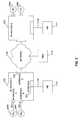
- FIG. 1illustrates an exemplary network environment
- FIG. 2depicts, in greater detail, a portion of the FIG. 2 network environment
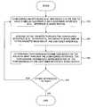
- FIG. 3is a flowchart showing exemplary steps for determining performance using an intelligent test probe
- FIG. 4illustrates an exemplary system environment
- FIG. 5is another flowchart showing exemplary steps for determining performance using an intelligent test probe
- FIG. 6illustrates another exemplary network environment
- FIG. 7illustrates the tunnels of the FIG. 6 network environment
- FIG. 8depicts loop back tests performed to remove the performance contributions of the test probe host (referred to as the Intelligent Network Element (INE);
- INEIntelligent Network Element
- FIG. 9is another flowchart showing exemplary steps for determining performance using an intelligent test probe.
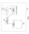
- FIG. 10depicts another exemplary network environment that includes a switch interfacing a local network.
- FIG. 1depicts an exemplary network environment 1000 consistent with one embodiment of the present invention.
- the network environment 1000includes one or more nodes A-C 1200 , 1300 , 1302 connected by a communication channel (e.g., a network) 1120 to one or more Intelligent Network Elements (INE) 1170 - 1171 and a Network Management System (NMS) 1175 , all of which will be described in greater detail below.
- INEIntelligent Network Elements
- NMSNetwork Management System
- Each of nodes A-C 1200 , 1300 , 1302represents a point on the network such as a processor, a router, a switch, a gateway, or any other communication or data processing device.
- Communication channel 1120may function as a communication network (or links) and may include, alone or in any suitable combination a telephony-based network, a local area network (LAN), a wide area network (WAN), a dedicated intranet, the Internet, a wireless network, or a bus. Further, any suitable combination of wired and/or wireless components and systems may be incorporated into the communication channels.
- the term “network”means a system of interconnected nodes including corresponding links and may include one or more of the components depicted in network environment 1000 .
- a connectionmeans a path, such as a link or a tunnel.
- the Intelligent Network Elements (INE) 1171 - 1170function to test an interface (also referred to as the “interface under test”) at a node (e.g., node 1200 ) by configuring another interface at the node, such that the “configured interface” has the same (or similar) quality of service (QoS) parameters to the QoS parameters of the interface under test.
- an interfacealso referred to as the “interface under test”
- QoSquality of service
- one INE 1170may generate packets and send these packets through the configured interface at node 1200 .
- the packets sent through the configured interfacemay be generated so that they are similar to the type of packets received at the interface under test.
- Another INE 1171may function to receive any generated packets.
- INE 1171may also use the received packets to determine one or more performance parameters for node 1200 , such as latency, jitter, or packet loss. These parameters serve to test the interface under test at node 1200 .
- the INEintelligently tests an interface at node 1200 by configuring another interface at the same node and sending packets through the other interface.
- the INEcan reconfigure the other interface to have the same (or similar) QoS parameters as those other interfaces under test, and can generate packets that are similar to the packet type received at each interface under test. If multiple nodes are present in network environment 1000 , INE 1170 can connect (either virtually or physically) to multiple nodes and test their interfaces. As such, systems and methods consistent with one embodiment of the present invention, reduces (if not eliminates) the need to have a test probe at each interface and at each node in a network.
- each of INE 1170 and 1171may be embodied to have the features disclosed in U.S. patent application Ser. No. 10/845,517, filed May 14, 2004, entitled “SYSTEMS AND METHODS FOR INFERRING SERVICES ON A NETWORK,” which is incorporated herein by reference in its entirety.
- Such featuresmay include participating in a network by, for example, receiving information, such as statistics, event information (e.g., network failures), and topology information (e.g., interfaces, links, and routes to other nodes); and providing information to NMS 1175 including information regarding each of nodes A-C 1200 , 1300 , 1302 or any other node (e.g., a router) in network environment 1000 .
- Network Management System (NMS) 1175may be embodied by one or more data processors. NMS 1175 may function to infer one or more services on network 1000 and to manage network 1000 .
- network managementincludes the execution of one or more functions for controlling, planning, allocating, deploying, coordinating, and/or monitoring the resources of a network.
- NMS 1175may aggregate information provided by the INEs and use that aggregate information to infer one or more services on the network.
- a servicee.g. an inferred service
- NMS 1175may be able to infer that one or more virtual private network services exist between nodes 1200 and 1300 by, for example, detecting route targets exported by node A 1200 and/or node B 1300 .
- BGP/MPLS VPNsthat describes route targets and BGP/MPLS (Border Gateway Protocol/Multiprotocol Label Switching) VPNs (draft-ieff-l3vpn-rfc2547bis-01.txt, E. Rosen et al., The Internet Society, September 2003, “BGP/MPLS IP VPNs).
- layer-3 type VPNssuch as BGP/MPLS VPNs
- other types of VPNsmay by inferred including, for example, layer-2 VPNs.
- FIG. 2depicts a portion of network environment 1000 in greater detail.
- node A 1200 and node B 1301are each depicted as a router
- communication channel 1120is depicted as an Internet Protocol (IP) network, such as the Internet.
- IPInternet Protocol
- Node A 1200may be embodied as a router, such as a Provider Edge (PE) router configured with BGP/MPLS (Border Gateway Protocol/Multiprotocol Label Switching) VPNs.
- PEProvider Edge
- BGP/MPLSBorder Gateway Protocol/Multiprotocol Label Switching
- One of ordinary skill in artwill recognize that commercially available software may be configured on node A to implement tunnels and corresponding BGP/MPLS VPNs.
- PE Router 1200may include interface A 201 to a Customer Edge device (CE A ) 2060 , interface B 202 to customer edge device (CE B ) 2061 , interface C 203 to INE 1170 , and interface D 204 to network 1120 .
- the interfacesmay be embodied as any type of physical interface including, for example, an Ethernet interface or a wireless interface.
- interface C 203 and INE 1170may be connected by a link 1121 which may be a direct connection or a network, such as network 1120 .
- Customer Edge devices 2060 - 2066may be embodied as any type of customer device, such as a Customer Edge (CE) router (see, e.g., RFC-2547) or any other edge device serving as an interface between a customer and a network.
- CECustomer Edge
- Node B 1301(labeled PE Router B) may be configured in a manner similar to PE Router A 1200 .
- FIG. 3is a flowchart with exemplary steps for determining the performance of a node (or the interfaces therein).
- INE 1170may configure an interface, such as interface C 203 , to have a similar QoS profile as customer interface A 201 , which is the “interface under test” (step 310 ).
- INE 1170may then send packets through the configured interface C 203 .
- the generated packets sent through interface C 203may be of the same type (e.g., header, protocol(s), and/or size) (step 320 ) as packets typically received at interface A 201 , such that the generated packets are injected into a tunnel (not shown) between PE Routers A and B 1200 , 1301 .
- INE 1171may then receive the packets from INE 1170 , interface C 203 , network 1120 , and PE Router 1301 .
- INE 1171may then determine one or more performance parameters based one the received packets (step 330 ). For the interface under test, INE 1171 may determine, based on the received packets, performance parameters, such as latency, jitter, and packet loss. If other interfaces require testing, INE 1170 may then repeat steps 310 - 330 for each of those interfaces (step 340 ). With the above general description, the following describes steps 310 - 340 in greater detail.
- a user of a network management systemmay select one or more virtual private networks (VPNs), such as BGP/MPLS VPNs, to monitor and test performance.
- VPNsvirtual private networks
- a usermay be prompted to select a specific customer, a customer's VPNs, a link (or connection), and/or specific services for that customer.
- VoIPVoice over IP
- a usermay select customer A's Voice over IP (VoIP) traffic only between New York and Los Angeles.
- VoIPVoice over IP
- the usermay be prompted to select how frequently the specific customer VPNs should be tested, the specific parameters to test, and/or any thresholds for generating alarms.
- the user's profiles for testingcan be saved in the INEs or, alternatively, NMS 1175 .
- INE 1170may issue a query to PE Router A 1200 .
- PE router Aserves as the head-end (or origin) of a tunnel from PE Router A 1200 to PE Router B 1301 .
- INE 1170may obtain the QoS profile associated with interface A 201 including, for example, the associated class(es) of service, queue priority, and/or drop precedence.
- INE 1170may simply retrieve the interface A 201 QoS Profile identifier and configure interface C 203 with the same QoS profile.
- INE 1170may query PE Router A 1200 by reading several MIB (Management Information Base) tables using the SNMP (Simple Network Management Protocol) or using a Command Line Interface (CLI). In some other embodiments, INE 1170 may determine the QoS profile of interface A 201 by discovering such information, as described in co-pending U.S. application U.S. patent application Ser. No. 10/845,517 entitled “SYSTEMS AND METHODS FOR INFERRING SERVICES ON A NETWORK”. In such discovery instances, NMS 1175 may store QoS information and any updates (changes and refreshes), allowing INE 1170 to simply read the QoS profile for interface A 201 from QoS information stored in NMS 1175 . The QoS profile information may then be configured at interface C 203 (or router 1200 ) by setting the interface using SNMP, CLI, or the like.
- MIBManagement Information Base
- SNMPSimple Network Management Protocol
- CLICommand Line Interface
- INE 1170may send packets through link 1121 and interface C 203 with the same (or similar) characteristics as packets received at interface A 201 . For example, if interface A 201 has a predetermined QoS Profile Identifier named “Platinum 1” associated with VoIP traffic at PE Router A 1200 , INE 1170 may generate packets that are of the same (or similar) type (in this example VoIP type packets) including header field(s), size, and/or protocol(s.) INE 1170 may then send the generated packets to interface C 203 .
- QoS Profile Identifiernamed “Platinum 1” associated with VoIP traffic at PE Router A 1200
- INE 1170may generate packets that are of the same (or similar) type (in this example VoIP type packets) including header field(s), size, and/or protocol(s.) INE 1170 may then send the generated packets to interface C 203 .
- PE Router Aapplies the Platinum 1 QoS profile and any associated rules (also known as tunnel injection criteria) that dictate how, when, and what traffic should be allowed access to a BGP/MPLS tunnel originating at PE Router A 1201 and terminating at PE Router B 1301 .
- Platinum 1 QoS profileand any associated rules (also known as tunnel injection criteria) that dictate how, when, and what traffic should be allowed access to a BGP/MPLS tunnel originating at PE Router A 1201 and terminating at PE Router B 1301 .
- packets received at interface A 201may be packets from customer 2061 with various destinations including, e.g., destinations 2064 and 2066 .
- INE 1170sets, based on the QoS profile and any corresponding injection criteria for the tunnel, one or more of the following header fields in the packets generated by the INE 1170 : (1) a DSCP (Differentiated Services Code Point) value that is indicative of the incoming priority of the packet; (2) an IP protocol number (e.g., based on the IP protocol, PE Router A 1200 may treat packets differently); (3) an application protocol number (if PE Router A 1200 is capable of treating different applications differently); and (4) source and destination IP addresses and/or ports.
- the injection criteriawould include rules that would allow or deny access to a BGP/MPLS tunnel from PE Router A 1200 to PE Router B 1300 based on, for example, one or more of the values associated with (1)-(4).
- INE 1171receives the packets from interfaces 203 and 204 , network 1120 (and the BGP/MPLS tunnel therein), PE Router 1301 , and link 1122 . Based on the received packet(s), INE 1171 will determine one or more performance parameters, such as latency, jitter, and/or packet loss. For example, if the packet generated by INE 1170 includes a time stamp, INE 1171 can measure latency, jitter, and packet loss at INE 1171 . Moreover, INE 1171 may perform additional processing to remove the effects of link 1121 and link 1122 , as will be described in greater detail below with respect to FIG. 8 . The determined one or more parameters represent the performance of the interface under test, which in this case is interface A 201 .
- INE 1170then repeats steps 310 - 330 for those interfaces (step 340 ). Otherwise, the process ends.
- Each of nodes A-C 1200 , 1301 , 1302 , INEs 1170 - 1171 , and NMS 1175may be implemented as a data processor, such as data processor 4000 depicted in block diagram form at FIG. 4 .
- Data processor 4000may include a central processing unit 4200 , a storage module 4500 , and/or an input/output (I/O) module 4300 .
- data processor 4000may include code, which configures CPU 4200 to function as a router or a switch.
- the router or switchmay represent one or more nodes on the network.
- the I/O module 4300may include one or more input/output (I/O) devices including a display 4350 , a keyboard, a mouse, an input storage device, and a network interface 4380 .
- Network interface 4380permits data processor 4000 to communicate through a network, such as communication channel 1120 .
- network interface 4380may be embodied as an Ethernet network interface card or a wireless LAN interface card, such as a card compatible with the IEEE 802.11 series of wireless LAN standards.
- display 4350is separate from data processor 4000 .
- display 4350may be provided on another data processor connected remotely to data processor 4000 .
- Central processing unit 4200may include, for example, one or more of the following: a central processing unit, a co-processor, memory, registers, and other processing devices and systems as appropriate. Moreover, unit 4200 (or associated memory) may include source code (not shown) that configures data processor to function as a router to route packets, such as IP packets. Moreover, such code may include code to configure the router to function as a router in a VPN, such as a BGP/MPLS VPN, including associated PE nodes and CE nodes used in BGP/MPLS VPNs, (see, e.g., RFC-2547, “BGP/MPLS VPNs,”).
- a VPNsuch as a BGP/MPLS VPN, including associated PE nodes and CE nodes used in BGP/MPLS VPNs, (see, e.g., RFC-2547, “BGP/MPLS VPNs,”).
- Storage module 4500may be embodied with a variety of components or subsystems capable of providing storage including, for example, a hard drive, an optical drive, a general-purpose storage device, a removable storage device, and/or memory. Moreover, storage module 4500 may include one or more of the following: network object information for each of the nodes of network 1000 , inferred network objects, inferred services, QoS profile information for one or more nodes, performance information for the one or more nodes, and any other information associated with network 1000 .
- CPU 4200is generally described in terms of data processor 4000 , CPU 4200 may also be incorporated into any other data processing or communication device including, for example, a router, a switch, a gateway, a bridge, and/or a network management system.
- each of nodes A-C 1200 , 1301 - 1302are embodied as routers; INEs 1170 - 1171 are embodied as a data processor incorporated into a high performance core router; and NMS 1175 is embodied as a data processor, such as a high performance work station (e.g., a SUN Fire E25K Server or a SUN V12 80).
- a high performance work statione.g., a SUN Fire E25K Server or a SUN V12 80.
- FIG. 5depicts another exemplary flowchart with steps for determining performance consistent with another embodiment of the present invention.
- INE 1170may determine which tunnels to test based on information stored at NMS 1175 (step 5100 ), with the tunnel corresponding to a service provided to a customer.
- INE 1170may determine a QoS profile for the customer's interface (e.g., interface A 1201 ) by querying PE Router A 1200 (step 5200 ).
- INE 1170may then configure an interface (e.g., interface C 203 ) at PE Router 1200 to have a similar QoS profile as interface A 201 , which is the interface under test (step 5300 ).
- INE 1170may also determine the injection criteria for the determined QoS profile (step 5400 ). Specifically, packets received at an interface with the determined QoS profile are processed with one or more rules (also referred to as “injection criteria”) that specify the criteria for allowing packets to access a BGP/MPLS tunnel between PE Router A 1200 and PE Router B 1301 . Next, INE 1170 generates packets that satisfy the determined injection criteria and then sends the generated packets to PE Router 1200 via link 1121 and interface C 203 (step 5500 ). Based on an injection criteria, PE Router A 1200 sends the generated packets to a BGP/MPLS tunnel between PE Router A 1200 and PE Router B 1301 .
- injection criteriaalso referred to as “injection criteria”
- INE 1171receives the generated packet from INE 1170 , interface C 203 , PE Router A 1200 , network 1120 , PE Router B 1301 , and link 1122 . INE 1171 may then initiate a test to determine performance based on one or more packets received from INE 1170 (step 5600 ). If there are other interfaces at PE Router A 1200 , INE 1170 may then test, using steps 5100 - 5600 , those other interfaces (step 5700 ). If there are other nodes, INE 1170 may then test, using steps 5100 - 5600 , those other nodes and their corresponding interfaces (step 5800 ). Otherwise, processing is complete.
- FIG. 6depicts the exemplary network environment of FIG. 2 with additional nodes.
- Network 1120is depicted as one or more links 450 - 482 .
- INE 1170is attached to the Ethernet interface of PE node D 452 .
- CE Arepresents a customer with traffic (e.g., VoIP packets).
- Customer CE A 2060may have a service level agreement (SLA) with a network service provider.
- SLAservice level agreement
- the SLAenables the customer to access a traffic-engineered tunnel(s) between PE node A 1200 and PE node B 1301 .
- tunnelsare shared across multiple customers (e.g., customers A and B 2060 - 2066 ) based on the agreed level of service associated with each customer and on the type of traffic that originates from each customer.
- customer CE A 2060may contract for “Platinum” level service with the network service provider.
- the Platinum QoS levelmay specify performance parameters (e.g., availability, delay, and packet loss) sufficient to satisfy the customer's delay sensitive VoIP voice traffic.
- the customermay contract for a different service level for other traffic, such as email, video, etc.
- the customermay have a SLA that specifies a lower, best efforts service (“Bronze” service) for email.
- customer CE B 's 2061may contract for “Platinum” level service for delay sensitive traffic, such as Voice Over IP (VoIP) traffic.
- VoIPVoice Over IP
- both CE A 's VoIP traffic and CE B VoIP trafficmay use the same tunnel between PE node A 1200 and PE node B 1301 since that tunnel has been engineered to satisfy VoIP traffic.
- FIG. 7depicts network 6000 with a tunnel 7100 , such as a BGP/MPLS tunnel between PE node A 1200 to PE node B 1301 .
- INE 1170may determine which tunnels to test based on information stored at NMS 1175 (step 5100 ), with the tunnel representative of a service provided to a customer.
- CE A 2060may have VoIP packet traffic for routing from PE Router A 1200 to PE Router B 1301 over tunnel 7100 .
- the VoIP trafficmay represent a service provided by a network service provider and guaranteed to satisfy a SLA, which specifies, inter alia, performance (e.g., availability, latency, packet loss, jitter, and the like).
- FIG. 7depicts a virtual connection (through a tunnel 7200 ) between INE 1170 and PE Router A 1200 .
- INE 1170may establish a virtual connection to PE Router A using a variety of techniques including, for example, a GRE (Generic Routing Encapsulation, RFC-2784) protocol, IP encapsulation within IP (also referred to as IP-IP tunneling), a VLAN (Virtual Local Area Network), and ATM PVC (Asynchronous Transfer Mode Permanent Virtual Circuit).
- GREGeneric Routing Encapsulation, RFC-2784
- IP-IP tunnelingalso referred to as IP-IP tunneling
- VLANVirtual Local Area Network
- ATM PVCAsynchronous Transfer Mode Permanent Virtual Circuit
- INE 1170may implement the Linux operating system with different IP addresses as “aliases” of the main INE 1170 IP address so that multiple GRE tunnels can be created between INE 1170 and PE Router A 1200 .
- aliasesthe IP addresses of the main INE 1170 IP address
- any other connection mechanismmay be used instead including VLAN mechanisms.
- two such tunnels 7200 , 7201are implemented to conduct a loop back test to characterize the GRE portion of the network. The characterization enables INE 1171 to remove the jitter, packet loss, latency contributions of the GRE tunnel 7200 from the tunnel of interest 7100 .
- INE 1170may determine a QoS profile for the customer CE A 2060 at PE Router A 1200 by querying the router (step 5200 ) or reading the profile information from NMS 1175 . INE 1170 may then configure another interface at PE Router A 1200 to have a similar (or the same) QoS profile as customer CE A 's interface (“interface under test”) (step 5300 ). INE 1170 may also determine the injection criteria for the determined QoS profile (step 5400 ). In particular, the injection criteria at PE Router A specify the type of packets that are allowed access to tunnel 7100 . For example, customer CE A 's VoIP packets may be allowed access to tunnel 7100 , but email packets may be denied.
- INE 1170generates packets (step 5500 ) that satisfy the determined injection criteria and sends the generated packets to PE Router A 1200 via link 1121 and interface 203 (not shown).
- INE 1170may generate packets that are similar to VoIP packets (e.g., similar header, structure, and/or size).
- INE 1170then sends the generated packets through GRE tunnel 7200 to PE Router A 1201 .
- PE Router A 1201then applies its injection criteria to the received packets, which should allow the generated packets to be granted access to tunnel 7100 (just like CE A 's VoIP packets which are granted access to tunnel 7100 ).
- INE 1170When INE 1170 generates packets that are “similar” to packets received at the interface under test from CE A , INE 1170 generates packets that are similar with respect to the injection criteria. For example, if packets received at the interface under test are injected into tunnel 7100 solely based on a specific header field (e.g., a DSCP field value), INE 1170 would generate packets that are similar with respect to having at least the same header field as the interface under test packets.
- a specific header fielde.g., a DSCP field value
- the injection criteriamay use the DSCP bits (for IP packets), EXP (for MPLS), Layer 2 information (VLAN-ID, logical L2 interface, L2 priority, etc.), and/or Layer 3+ information (protocol numbers, ports, transport layer status, etc.) to route a packet to a tunnel (or route) that satisfies the required (or specified) QoS for that packet.
- the injection criteriathus provide rules for packet selection and injection on to a route, such as a tunnel.
- a service providermay define three levels of QoS.
- the three service levelsmay consist of Best Efforts (BE), Expedited Forwarding (EF), and Assured Forwarding (AF).
- BEBest Efforts
- EFExpedited Forwarding
- AFAssured Forwarding
- IP routing trafficmay receive BE service
- voicemay receive EF service
- video/multimedia signaling data and priority datamay receive AF service.
- a service providermay specify a default injection criteria that routes traffic to predetermined path(s), such as a BGP/MPLS tunnel. Moreover, the service provider may establish the path by specifying or configuring one or more of the following: rate (bandwidth), depth (available buffer space in a queue), Rmax (queue length at which there is a 100% probability of dropping a packet), peak rate (peak rate for a link), minimum policed unit (see, e.g. RFC-2212, “Specification of Guaranteed Quality of Service,” S.
- a service providermay define another set of tunnels for packets satisfying the following injection criteria: EXP, DSCP, ILM (Incoming Label Map), VRF, IP Protocol (L3+), etc.
- a service providermay define yet another set of tunnels for packets satisfying other injection criteria values.
- a service providermay establish the EF and AF paths to have specific parameters, such as rate, depth, etc.
- PE Router B 1301receives the generated packets from tunnel 7100 and routes those packets to GRE tunnel 7204 and INE 1171 .
- INE 1171may then initiate tests of the received packet(s) to determine performance (step 5600 ).
- INE 1171removes the packet loss, jitter, and latency effects of the GRE tunnels 7204 and 7200 , so that the determined performance measurements represent only tunnel 7100 .
- One way to correct for the GRE tunnel portion 7200is to use the traditional “ping” protocol utility (from the INE to the PE) on the GRE Tunnel 7200 and use the results to correct for the error introduced by the GRE tunnel 7200 .
- Another pingcan be performed over GRE tunnel 7204 .
- the results of the ping testswhich provide time to traverse the tunnels, can be used to remove the effects of each of tunnels 7200 and 7204 .
- a more accurate approachis to use a loop back (also referred to as a second tunnel approach). For example, to correct for GRE tunnel 7200 , tunnel 7201 is established, and to correct for tunnel 7204 , tunnel 7203 is established, as shown in FIG. 7 .
- FIG. 8depicts the tests performed by INE 1170 and 1171 to reduce (if not eliminate) the effects of GRE tunnels 7200 and 7204 . Since 7200 and 7204 are not part of the path (i.e., tunnel 7100 ) for the interface of under test, the jitter, latency, and packet loss effects of GRE tunnels 7200 and 7204 should be removed from performance calculations made for the interface under test.
- INE 1171determines the time T 1 , which represents the end-to-end latency (time) measured between INE 1170 (as source) to INE 1171 (as destination).
- INE 1170determines time T 2 by performing a loop back test, sending one or more packets (with time stamps) to tunnel 7200 , PE Router A 1200 , and returning on tunnel 7201 . Meanwhile, INE 1171 determines time T 3 by performing a loop back test, sending one or more packets (with time stamps) to tunnel 7203 , PE Router B 1301 , and returning on tunnel 7204 .
- INE 1171determines the value of “12” which represents the latency between PE Routers A and B.
- the generated test packetsare time stamped to facilitate performance testing, as note above.
- the time stampmay be applied at the INE 1170 or PE Router A 1200 .
- the time stampmay be applied to a packet at (or near) network interface 204 of PE Router A 1200 rather than at INE 1170 .
- a time stampis affixed to one or more packets at periodic intervals
- the timing and packet losscan readily be determined. For example, if an INE generates a packet with a corresponding time stamp every one millisecond, the receiving INE can determine if a packet is missing—representing a packet loss—and the timing associated with the packet loss.
- INE 1170may then test, using steps 5100 - 5600 , each of those other interfaces (step 5700 ). If there are other nodes, INE 1170 may virtually connect to each of those nodes and then test each of those nodes (e.g., PE E 453 ) using steps 5100 - 5600 and their corresponding interfaces (step 5800 ).
- FIG. 9depicts another exemplary flowchart with steps for determining performance consistent with another embodiment of the present invention.
- INE 1170may determine which tunnels correspond to a customer based on customer information stored at NMS 1175 (step 9100 ).
- the customer information stored at NMS 1175may indicate that Customer A is connected to PE Routers A and B 1200 and 1301 and there are tunnel(s) between the routers.
- INE 1170may determine which one of the tunnels to test (step 9200 ).
- the determination of which tunnel to testmay be based on information stored in NMS 1175 or may be driven by an event, such as an alarm, a failure, or degradation of network performance.
- the determination of which tunnel to testmay be based on a schedule (e.g., hourly, daily, weekly, etc.), such as a user defined schedule stored in NMS 1175 .
- INE 1170may determine a QoS profile for the customer's interface (e.g., interface A 1201 ) by querying PE Router A 1200 , and then configure the interface (e.g., interface C 203 ) at PE Router 1200 to have a similar QoS profile (e.g., same rate, buffer size, etc.) as interface A 201 , which is the interface under test (steps 9310 - 9410 ). Meanwhile, INE 1170 may determine the injection criteria for the determined QoS profile, and then generate packets (steps 9305 - 9405 ).
- a QoS profilefor the customer's interface (e.g., interface A 1201 ) by querying PE Router A 1200 , and then configure the interface (e.g., interface C 203 ) at PE Router 1200 to have a similar QoS profile (e.g., same rate, buffer size, etc.) as interface A 201 , which is the interface under test (steps 9310 - 9410
- the generated packetsare defined such that they should be treated by PE Router 1200 in a manner similar to the packets received from interface A 201 , with, for example, the generated packets having similar (or the same structure) in terms of header and size.
- the packetsmay have the same header fields (DSCP, EXP, etc.) and protocols (e.g., protocol numbers), as the packets received from the customer's interface A 201 , the interface under test.
- INE 1170may then initiate a test of the interface under test, which in this case is interface A 201 , by sending one or more packets from INE 1170 to INE 1171 through interface C 203 , PE Router A, interface D 204 , network 1120 , PE Router 1301 , and link 1122 . If there are other tunnels to test, INE 1170 repeats steps 9100 - 9700 (step 9800 ). Some of the other tunnels may be at nodes other than node 1200 . Otherwise, processing is complete.
- FIG. 10depicts another exemplary network environment 10000 consistent with the present invention.
- FIG. 10includes a switch 10100 .
- Switch 10100may be any type of switch, such as an ATM switch, an Ethernet (e.g., Gigabit Ethernet) switch, or a wireless switch interface.
- switch 10100serves as an interface between network 1120 and a second network (labeled local loop network) 10200 .
- Network 10200may be embodied in a manner similar to network 1120 .
- network 10200may be considered part of the same overall network as network 1120 , in FIG. 10 functions as a separate network.
- local loop network 10200may be a wireless network for providing local access to customers, a local exchange carrier (LEC) network for providing local access to customers, or cable television drops to homes which provide local network access to customers.
- LEClocal exchange carrier
- INE 1170may connect to PE Router A 1200 through switch 10100 .
- INE 1170(or NMS 1175 ) may “sectionalize” the failure by determining the performance of switch 10100 . For example, if customer 2061 is having performance problems (e.g., cannot access customer 2604 ), INE 1170 (or NMS 1175 ) may be able to determine which section of the overall network is causing the problem. If an SNMP query of switch 10100 determines that the switch is operating correctly, INE 1170 may identify a cause within another “section” of network 1120 .
- INE 1170may identify the cause as the local loop network 10200 “section” (or possibly the switch 10100 itself). In some embodiments, the use of switch 10100 may also improve latency measurements between INE 1170 and PE Router A 1200 (e.g., where the link includes a more deterministic switch 10100 ).
- INEs 1171 and 1170may emulate one or more aspects of a CE router, as specified in RFC-2547 titled “BGP/MPLS VPNs.”
- Systems and methods consistent with the present inventionalso include computer readable media that include program instruction or code for performing various computer-implemented operations based on the methods and processes of the invention.
- the media and program instructionsmay be those specially designed and constructed for the purposes of the invention, or they may be of the kind well known and available to those having skill in the computer software arts.
- the computer readable mediamay be in the form of a signal on a carrier wave or may be in the form of a storage media such as a disk.
- Examples of program instructionsinclude, for example, machine code, such as produced by a compiler, and files containing a high level code that can be executed by the computer using an interpreter.
Landscapes
- Engineering & Computer Science (AREA)
- Computer Networks & Wireless Communication (AREA)
- Signal Processing (AREA)
- Environmental & Geological Engineering (AREA)
- Quality & Reliability (AREA)
- Data Exchanges In Wide-Area Networks (AREA)
Abstract
Description
l1+l2+l3=T1 Equation (1) and
l2=T1−(l1+l3) Equation (2)
where l1represents the latency between
l1+l1′=T2 Equation (3) and
l3+l3′=T3 Equation (4);
where l3′ represents latency between
l1≈l1′ andl3≈l3′.
l1=T2/2 andl3=T3/2 Equations (5) and (6).
l2=T1−(T2+T3)/2 Equation (7).
Claims (31)
Priority Applications (2)
| Application Number | Priority Date | Filing Date | Title |
|---|---|---|---|
| US10/903,586US8130661B2 (en) | 2003-08-01 | 2004-08-02 | Systems and methods for intelligent probe testing |
| US13/412,615US20120163227A1 (en) | 2003-08-01 | 2012-03-06 | Systems and methods for intelligent probe testing |
Applications Claiming Priority (3)
| Application Number | Priority Date | Filing Date | Title |
|---|---|---|---|
| US49156603P | 2003-08-01 | 2003-08-01 | |
| US57716504P | 2004-06-07 | 2004-06-07 | |
| US10/903,586US8130661B2 (en) | 2003-08-01 | 2004-08-02 | Systems and methods for intelligent probe testing |
Related Child Applications (1)
| Application Number | Title | Priority Date | Filing Date |
|---|---|---|---|
| US13/412,615ContinuationUS20120163227A1 (en) | 2003-08-01 | 2012-03-06 | Systems and methods for intelligent probe testing |
Publications (2)
| Publication Number | Publication Date |
|---|---|
| US20050094567A1 US20050094567A1 (en) | 2005-05-05 |
| US8130661B2true US8130661B2 (en) | 2012-03-06 |
Family
ID=34557290
Family Applications (2)
| Application Number | Title | Priority Date | Filing Date |
|---|---|---|---|
| US10/903,586Active2028-03-01US8130661B2 (en) | 2003-08-01 | 2004-08-02 | Systems and methods for intelligent probe testing |
| US13/412,615AbandonedUS20120163227A1 (en) | 2003-08-01 | 2012-03-06 | Systems and methods for intelligent probe testing |
Family Applications After (1)
| Application Number | Title | Priority Date | Filing Date |
|---|---|---|---|
| US13/412,615AbandonedUS20120163227A1 (en) | 2003-08-01 | 2012-03-06 | Systems and methods for intelligent probe testing |
Country Status (1)
| Country | Link |
|---|---|
| US (2) | US8130661B2 (en) |
Cited By (7)
| Publication number | Priority date | Publication date | Assignee | Title |
|---|---|---|---|---|
| US20090327903A1 (en)* | 2006-07-06 | 2009-12-31 | Referentia Systems, Inc. | System and Method for Network Topology and Flow Visualization |
| US20110305143A1 (en)* | 2009-02-23 | 2011-12-15 | Eric Gray | Maximum transmission unit (mtu) size discovery mechanism and method for data-link layers |
| US20140269399A1 (en)* | 2013-03-12 | 2014-09-18 | Cisco Technology, Inc. | Multiple test site bandwidth limit measurement |
| US9391716B2 (en) | 2010-04-05 | 2016-07-12 | Microsoft Technology Licensing, Llc | Data center using wireless communication |
| US9497039B2 (en) | 2009-05-28 | 2016-11-15 | Microsoft Technology Licensing, Llc | Agile data center network architecture |
| US9954751B2 (en) | 2015-05-29 | 2018-04-24 | Microsoft Technology Licensing, Llc | Measuring performance of a network using mirrored probe packets |
| US11374836B1 (en) | 2020-12-09 | 2022-06-28 | Microsoft Technology Licensing, Llc | Network link testing using IP-in-IP encapsulation |
Families Citing this family (56)
| Publication number | Priority date | Publication date | Assignee | Title |
|---|---|---|---|---|
| GB0323453D0 (en)* | 2003-10-07 | 2003-11-05 | Nokia Corp | Quality of service in communication systems |
| US20050226161A1 (en)* | 2004-04-06 | 2005-10-13 | Jaworski Richard C | System for monitoring the upstream and downstream cable modem channel |
| US7664043B1 (en) | 2004-07-01 | 2010-02-16 | At&T Corp. | Method and apparatus for performing reachability testing within the context of customer virtual private networks |
| GB2418795A (en)* | 2004-10-01 | 2006-04-05 | Agilent Technologies Inc | Monitoring traffic in a packet switched network |
| US7440407B2 (en)* | 2005-02-07 | 2008-10-21 | At&T Corp. | Method and apparatus for centralized monitoring and analysis of virtual private networks |
| US7633876B2 (en)* | 2005-08-22 | 2009-12-15 | At&T Intellectual Property I, L.P. | System and method for monitoring a switched metro ethernet network |
| US8170045B2 (en)* | 2005-10-24 | 2012-05-01 | Cisco Technology, Inc. | Class-based bandwidth partitioning |
| US20070140133A1 (en)* | 2005-12-15 | 2007-06-21 | Bellsouth Intellectual Property Corporation | Methods and systems for providing outage notification for private networks |
| US20070140135A1 (en)* | 2005-12-15 | 2007-06-21 | Bellsouth Intellectual Property Corporation | Methods and systems for providing performance testing for private networks |
| JP4583312B2 (en)* | 2006-01-30 | 2010-11-17 | 富士通株式会社 | Communication status determination method, communication status determination system, and determination device |
| US8966113B2 (en)* | 2006-03-03 | 2015-02-24 | Cisco Technology, Inc. | Technique for dynamically restoring original TE-LSP attributes for interdomain TE-LSPs |
| US8004973B2 (en)* | 2006-04-25 | 2011-08-23 | Citrix Systems, Inc. | Virtual inline configuration for a network device |
| US7843820B2 (en)* | 2006-10-30 | 2010-11-30 | Research In Motion Limited | Wi-Fi quality of service signaling |
| US7844719B2 (en)* | 2007-02-13 | 2010-11-30 | Cisco Technology, Inc. | Tunnel availability detection with reduced control plane overhead |
| US8195478B2 (en)* | 2007-03-07 | 2012-06-05 | Welch Allyn, Inc. | Network performance monitor |
| KR101019210B1 (en)* | 2007-04-25 | 2011-03-04 | 이화여자대학교 산학협력단 | Embedded software test device using emulation and method |
| US9118433B2 (en)* | 2007-05-07 | 2015-08-25 | Alcatel Lucent | GPON OAM using IEEE 802.1ag methodology |
| US20090086639A1 (en)* | 2007-09-27 | 2009-04-02 | Verizon Services Corp. | Testing dynamically addressed network devices |
| US8549341B2 (en)* | 2008-08-29 | 2013-10-01 | Netlogic Microsystems, Inc. | System and method for reducing latency associated with timestamps in a multi-core, multi-threaded processor |
| US10320635B2 (en)* | 2009-06-11 | 2019-06-11 | Talari Networks Incorported | Methods and apparatus for providing adaptive private network centralized management system timestamp correlation processes |
| WO2011026264A1 (en)* | 2009-09-01 | 2011-03-10 | 华为技术有限公司 | Method and apparatus for detecting multi-service performance in tunnel |
| US9836376B2 (en) | 2009-09-24 | 2017-12-05 | Contec, Llc | Method and system for automated test of end-user devices |
| US8234401B2 (en) | 2010-06-30 | 2012-07-31 | Cisco Technology, Inc. | Adaptive policers responsive to utilization levels of a resource |
| US8718071B2 (en) | 2010-09-10 | 2014-05-06 | Futurewei Technologies, Inc. | Method to pass virtual local area network information in virtual station interface discovery and configuration protocol |
| JP5581489B2 (en)* | 2010-09-29 | 2014-09-03 | 株式会社Pfu | Node monitoring apparatus, node monitoring method, and node monitoring program |
| EP2686982B1 (en)* | 2011-03-15 | 2020-06-03 | Hewlett-Packard Enterprise Development LP | Quantifying available service-level capacity of a network for projected network traffic |
| US8831110B2 (en)* | 2011-07-20 | 2014-09-09 | James D. Ocon | Electronic news gathering method and system for the prioritized transmission of data |
| US9570124B2 (en) | 2012-01-11 | 2017-02-14 | Viavi Solutions Inc. | High speed logging system |
| EP2832048A1 (en)* | 2012-03-27 | 2015-02-04 | Nokia Solutions and Networks Oy | Mapping selective dscp values to gtp-u |
| US9537729B2 (en) | 2013-08-09 | 2017-01-03 | Hewlett Packard Enterprise Development Lp | Network switching device for quantifying available service-level capacity of a network for projected network traffic |
| US9379992B2 (en)* | 2013-12-25 | 2016-06-28 | Cavium, Inc. | Method and an apparatus for virtualization of a quality-of-service |
| US10439908B2 (en) | 2014-12-23 | 2019-10-08 | Talari Networks Incorporated | Methods and apparatus for providing adaptive private network centralized management system time correlated playback of network traffic |
| WO2017053961A1 (en)* | 2015-09-25 | 2017-03-30 | Contec, Llc | Universal device testing system |
| US9838295B2 (en)* | 2015-11-23 | 2017-12-05 | Contec, Llc | Wireless routers under test |
| US10122611B2 (en) | 2015-09-25 | 2018-11-06 | Contec, Llc | Universal device testing interface |
| US20170126536A1 (en) | 2015-10-30 | 2017-05-04 | Contec, Llc | Hardware Architecture for Universal Testing System: Cable Modem Test |
| US10320651B2 (en) | 2015-10-30 | 2019-06-11 | Contec, Llc | Hardware architecture for universal testing system: wireless router test |
| US9900116B2 (en) | 2016-01-04 | 2018-02-20 | Contec, Llc | Test sequences using universal testing system |
| US10277497B2 (en) | 2015-09-25 | 2019-04-30 | Contec, Llc | Systems and methods for testing electronic devices using master-slave test architectures |
| US10291959B2 (en) | 2015-09-25 | 2019-05-14 | Contec, Llc | Set top boxes under test |
| US9960989B2 (en) | 2015-09-25 | 2018-05-01 | Contec, Llc | Universal device testing system |
| US9810735B2 (en) | 2015-09-25 | 2017-11-07 | Contec, Llc | Core testing machine |
| US9992084B2 (en) | 2015-11-20 | 2018-06-05 | Contec, Llc | Cable modems/eMTAs under test |
| US9900113B2 (en) | 2016-02-29 | 2018-02-20 | Contec, Llc | Universal tester hardware |
| US10779056B2 (en) | 2016-04-14 | 2020-09-15 | Contec, Llc | Automated network-based test system for set top box devices |
| US10462456B2 (en) | 2016-04-14 | 2019-10-29 | Contec, Llc | Automated network-based test system for set top box devices |
| US10284456B2 (en) | 2016-11-10 | 2019-05-07 | Contec, Llc | Systems and methods for testing electronic devices using master-slave test architectures |
| US10205805B2 (en) | 2016-11-21 | 2019-02-12 | Cisco Technology, Inc. | Dropping or admitting packets to an output queue using policy-based scheduling and virtual destination queue occupancy values |
| US10320686B2 (en) | 2016-12-07 | 2019-06-11 | Cisco Technology, Inc. | Load balancing eligible packets in response to a policing drop decision |
| EP3364600B1 (en)* | 2017-02-20 | 2021-05-26 | Deutsche Telekom AG | Monitoring of data rates |
| US10523528B2 (en)* | 2017-05-22 | 2019-12-31 | Cisco Technology, Inc. | Determination of quality of service of a network tunnel |
| US11082337B2 (en)* | 2019-02-15 | 2021-08-03 | Juniper Networks, Inc. | Support for multiple virtual networks over an underlay network topology |
| US10917326B1 (en)* | 2019-08-23 | 2021-02-09 | Keysight Technologies, Inc. | Methods, systems, and computer readable media for debugging test traffic generation |
| US12218835B2 (en) | 2020-05-22 | 2025-02-04 | Juniper Networks, Inc. | Bitmask route target in targeted distribution of information using a routing protocol |
| US11916777B2 (en) | 2021-07-06 | 2024-02-27 | Cisco Technology, Inc. | Learning SLA violation probability from intelligent fine grained probing |
| US12160355B2 (en)* | 2021-07-30 | 2024-12-03 | Cisco Technology, Inc. | Network monitoring agent hubs |
Citations (19)
| Publication number | Priority date | Publication date | Assignee | Title |
|---|---|---|---|---|
| US4545011A (en)* | 1979-01-29 | 1985-10-01 | Infinet Inc. | Enhanced communications network testing and control system |
| US5610905A (en)* | 1993-07-19 | 1997-03-11 | Alantec Corporation | Communication apparatus and methods |
| US5748612A (en)* | 1995-08-10 | 1998-05-05 | Mcdata Corporation | Method and apparatus for implementing virtual circuits in a fibre channel system |
| US5878032A (en)* | 1997-11-07 | 1999-03-02 | Northern Telecom Limited | Delay monitoring of telecommunication networks |
| EP0957432A2 (en) | 1998-05-11 | 1999-11-17 | International Business Machines Corporation | Client-based application availability and response monitoring and reporting for distributed computing environments |
| US6104700A (en)* | 1997-08-29 | 2000-08-15 | Extreme Networks | Policy based quality of service |
| WO2002051181A1 (en) | 2000-12-20 | 2002-06-27 | Telefonaktiebolaget Lm Ericsson (Publ) | Method and means for testing the performance of a network node in a radio communication system |
| US20020167936A1 (en) | 2001-05-14 | 2002-11-14 | Lee Goodman | Service level agreements based on objective voice quality testing for voice over IP (VOIP) networks |
| US20040034492A1 (en)* | 2001-03-30 | 2004-02-19 | Conway Adrian E. | Passive system and method for measuring and monitoring the quality of service in a communications network |
| US6717914B1 (en)* | 1999-05-27 | 2004-04-06 | 3Com Corporation | System for probing switched virtual circuits in a connection oriented network |
| US20040088405A1 (en)* | 2002-11-01 | 2004-05-06 | Vikas Aggarwal | Distributing queries and combining query responses in a fault and performance monitoring system using distributed data gathering and storage |
| US20040153854A1 (en)* | 2003-01-10 | 2004-08-05 | Andiamo Systems, Inc. | Port analyzer adapter |
| US6775826B1 (en)* | 2001-02-26 | 2004-08-10 | Emc Corporation | System and method for replaying workload data in a data storage environment |
| EP1447940A2 (en) | 2003-02-12 | 2004-08-18 | Ubinetics Limited | Method for measuring a user perception score |
| US20040223500A1 (en)* | 2003-05-08 | 2004-11-11 | Onvoy, Inc. | Communications network with converged services |
| US6950405B2 (en)* | 2001-07-16 | 2005-09-27 | Agilent Technologies, Inc. | Traffic stream generator having a non-consecutive addressing mechanism |
| US6963575B1 (en)* | 2000-06-07 | 2005-11-08 | Yipes Enterprise Services, Inc. | Enhanced data switching/routing for multi-regional IP over fiber network |
| US20070041329A1 (en)* | 2005-08-22 | 2007-02-22 | Sbc Knowledge Ventures, L.P. | System and method for monitoring a switched metro ethernet network |
| US7516211B1 (en)* | 2003-08-05 | 2009-04-07 | Cisco Technology, Inc. | Methods and apparatus to configure a communication port |
- 2004
- 2004-08-02USUS10/903,586patent/US8130661B2/enactiveActive
- 2012
- 2012-03-06USUS13/412,615patent/US20120163227A1/ennot_activeAbandoned
Patent Citations (19)
| Publication number | Priority date | Publication date | Assignee | Title |
|---|---|---|---|---|
| US4545011A (en)* | 1979-01-29 | 1985-10-01 | Infinet Inc. | Enhanced communications network testing and control system |
| US5610905A (en)* | 1993-07-19 | 1997-03-11 | Alantec Corporation | Communication apparatus and methods |
| US5748612A (en)* | 1995-08-10 | 1998-05-05 | Mcdata Corporation | Method and apparatus for implementing virtual circuits in a fibre channel system |
| US6104700A (en)* | 1997-08-29 | 2000-08-15 | Extreme Networks | Policy based quality of service |
| US5878032A (en)* | 1997-11-07 | 1999-03-02 | Northern Telecom Limited | Delay monitoring of telecommunication networks |
| EP0957432A2 (en) | 1998-05-11 | 1999-11-17 | International Business Machines Corporation | Client-based application availability and response monitoring and reporting for distributed computing environments |
| US6717914B1 (en)* | 1999-05-27 | 2004-04-06 | 3Com Corporation | System for probing switched virtual circuits in a connection oriented network |
| US6963575B1 (en)* | 2000-06-07 | 2005-11-08 | Yipes Enterprise Services, Inc. | Enhanced data switching/routing for multi-regional IP over fiber network |
| WO2002051181A1 (en) | 2000-12-20 | 2002-06-27 | Telefonaktiebolaget Lm Ericsson (Publ) | Method and means for testing the performance of a network node in a radio communication system |
| US6775826B1 (en)* | 2001-02-26 | 2004-08-10 | Emc Corporation | System and method for replaying workload data in a data storage environment |
| US20040034492A1 (en)* | 2001-03-30 | 2004-02-19 | Conway Adrian E. | Passive system and method for measuring and monitoring the quality of service in a communications network |
| US20020167936A1 (en) | 2001-05-14 | 2002-11-14 | Lee Goodman | Service level agreements based on objective voice quality testing for voice over IP (VOIP) networks |
| US6950405B2 (en)* | 2001-07-16 | 2005-09-27 | Agilent Technologies, Inc. | Traffic stream generator having a non-consecutive addressing mechanism |
| US20040088405A1 (en)* | 2002-11-01 | 2004-05-06 | Vikas Aggarwal | Distributing queries and combining query responses in a fault and performance monitoring system using distributed data gathering and storage |
| US20040153854A1 (en)* | 2003-01-10 | 2004-08-05 | Andiamo Systems, Inc. | Port analyzer adapter |
| EP1447940A2 (en) | 2003-02-12 | 2004-08-18 | Ubinetics Limited | Method for measuring a user perception score |
| US20040223500A1 (en)* | 2003-05-08 | 2004-11-11 | Onvoy, Inc. | Communications network with converged services |
| US7516211B1 (en)* | 2003-08-05 | 2009-04-07 | Cisco Technology, Inc. | Methods and apparatus to configure a communication port |
| US20070041329A1 (en)* | 2005-08-22 | 2007-02-22 | Sbc Knowledge Ventures, L.P. | System and method for monitoring a switched metro ethernet network |
Non-Patent Citations (3)
| Title |
|---|
| D. Farinacci et al., The Internet Society, "Generic Routing Encapsulation," (RFS-2784) 2000. |
| E. Rosen et al., The Internet Society, "BGP/MPLS VPNs," (RFS-2547) 1999. |
| S. Shenker et al., The Internet Society, "Specification of Guaranteed Quality of Service," (RFC-2212) 1997. |
Cited By (14)
| Publication number | Priority date | Publication date | Assignee | Title |
|---|---|---|---|---|
| US9350622B2 (en) | 2006-07-06 | 2016-05-24 | LiveAction, Inc. | Method and system for real-time visualization of network flow within network device |
| US9003292B2 (en)* | 2006-07-06 | 2015-04-07 | LiveAction, Inc. | System and method for network topology and flow visualization |
| US9240930B2 (en) | 2006-07-06 | 2016-01-19 | LiveAction, Inc. | System for network flow visualization through network devices within network topology |
| US9246772B2 (en) | 2006-07-06 | 2016-01-26 | LiveAction, Inc. | System and method for network topology and flow visualization |
| US20090327903A1 (en)* | 2006-07-06 | 2009-12-31 | Referentia Systems, Inc. | System and Method for Network Topology and Flow Visualization |
| US20110305143A1 (en)* | 2009-02-23 | 2011-12-15 | Eric Gray | Maximum transmission unit (mtu) size discovery mechanism and method for data-link layers |
| US8811190B2 (en)* | 2009-02-23 | 2014-08-19 | Telefonaktiebolaget Lm Ericsson (Publ) | Maximum transmission unit (MTU) size discovery mechanism and method for data-link layers |
| US9497039B2 (en) | 2009-05-28 | 2016-11-15 | Microsoft Technology Licensing, Llc | Agile data center network architecture |
| US9391716B2 (en) | 2010-04-05 | 2016-07-12 | Microsoft Technology Licensing, Llc | Data center using wireless communication |
| US10110504B2 (en) | 2010-04-05 | 2018-10-23 | Microsoft Technology Licensing, Llc | Computing units using directional wireless communication |
| US9331925B2 (en)* | 2013-03-12 | 2016-05-03 | Cisco Technology, Inc. | Multiple test site bandwidth limit measurement |
| US20140269399A1 (en)* | 2013-03-12 | 2014-09-18 | Cisco Technology, Inc. | Multiple test site bandwidth limit measurement |
| US9954751B2 (en) | 2015-05-29 | 2018-04-24 | Microsoft Technology Licensing, Llc | Measuring performance of a network using mirrored probe packets |
| US11374836B1 (en) | 2020-12-09 | 2022-06-28 | Microsoft Technology Licensing, Llc | Network link testing using IP-in-IP encapsulation |
Also Published As
| Publication number | Publication date |
|---|---|
| US20050094567A1 (en) | 2005-05-05 |
| US20120163227A1 (en) | 2012-06-28 |
Similar Documents
| Publication | Publication Date | Title |
|---|---|---|
| US8130661B2 (en) | Systems and methods for intelligent probe testing | |
| US8010643B2 (en) | System and methods for simulating traffic generation | |
| US20200235999A1 (en) | Network multi-source inbound quality of service methods and systems | |
| US8400941B2 (en) | Systems and methods for inferring services on a network | |
| EP1861963B1 (en) | System and methods for identifying network path performance | |
| US7843843B1 (en) | Adaptive, application-aware selection of differntiated network services | |
| US7496661B1 (en) | Adaptive, application-aware selection of differentiated network services | |
| CN100463418C (en) | Network performance testing method, system and network equipment | |
| KR101445468B1 (en) | Method, system and apparatus providing secure infrastructure | |
| JP4567367B2 (en) | Insert address to enable OAM function | |
| US9819586B2 (en) | Network-based ethernet switching packet switch, network, and method | |
| US8160055B1 (en) | System and methods for identifying network path performance | |
| US20090161569A1 (en) | System and method for facilitating carrier ethernet performance and quality measurements | |
| WO2017037615A1 (en) | A method and apparatus for modifying forwarding states in a network device of a software defined network | |
| US20220286395A1 (en) | SRv6 Segment Identifiers and Micro Segments Invoking Network Behavior including Realization of Network Slices | |
| WO2006105707A1 (en) | A network performance testing method and the system, the device thereof | |
| Silalahi et al. | Application of MPLS Tunnel Service L2TP-VPN Optimization Concept with Traffic Engineering Method for Looping-Protection Service Analysis | |
| Lewis et al. | Selecting Mpls Vpn Services | |
| EP1683301B1 (en) | Systems and methods for intelligent probe testing | |
| Surantha | Design and Evaluation of Enterprise Network with Converged Services | |
| Makeri | Design and Implementation of optimized features in a local area network for improvedenterprisenetwork | |
| Daba | Quality of Service Comparison of Seamless Multi-Protocol Level Switching and Multi-Protocol Level Switching Networks | |
| WO2025201632A1 (en) | Testing for intent management system | |
| Chidozie | Design and implementation of optimized features in a local area network for improved enterprise | |
| WO2025077998A1 (en) | Explainability over intent management interfaces |
Legal Events
| Date | Code | Title | Description |
|---|---|---|---|
| AS | Assignment | Owner name:WEST RIDGE NETWORKS, INC., MASSACHUSETTS Free format text:ASSIGNMENT OF ASSIGNORS INTEREST;ASSIGNORS:KANNAN, NAVNEETH N.;GRAY, ERIC W.;REEL/FRAME:016140/0735;SIGNING DATES FROM 20040117 TO 20041229 Owner name:WEST RIDGE NETWORKS, INC., MASSACHUSETTS Free format text:ASSIGNMENT OF ASSIGNORS INTEREST;ASSIGNORS:KANNAN, NAVNEETH N.;GRAY, ERIC W.;SIGNING DATES FROM 20040117 TO 20041229;REEL/FRAME:016140/0735 | |
| AS | Assignment | Owner name:SQMWORKS, INC., MASSACHUSETTS Free format text:ASSIGNMENT OF ASSIGNORS INTEREST;ASSIGNOR:WEST RIDGE NETWORKS, INC.;REEL/FRAME:017742/0144 Effective date:20050812 | |
| AS | Assignment | Owner name:OPNET TECHNOLOGIES, INC., MARYLAND Free format text:ASSIGNMENT OF ASSIGNORS INTEREST;ASSIGNOR:SQMWORKS, INC.;REEL/FRAME:017995/0459 Effective date:20060419 | |
| AS | Assignment | Owner name:SQMWORKS, INC., MASSACHUSETTS Free format text:CORRECTIV;ASSIGNOR:WEST RIDGE NETWORKS, INC.;REEL/FRAME:022564/0103 Effective date:20050812 Owner name:SQMWORKS, INC., MASSACHUSETTS Free format text:CORRECTIVE ASSIGNMENT-SEE ATTACHED;ASSIGNOR:WEST RIDGE NETWORKS, INC.;REEL/FRAME:022564/0103 Effective date:20050812 | |
| STCF | Information on status: patent grant | Free format text:PATENTED CASE | |
| FEPP | Fee payment procedure | Free format text:PAYOR NUMBER ASSIGNED (ORIGINAL EVENT CODE: ASPN); ENTITY STATUS OF PATENT OWNER: LARGE ENTITY | |
| AS | Assignment | Owner name:MORGAN STANLEY & CO. LLC, MARYLAND Free format text:SECURITY AGREEMENT;ASSIGNORS:RIVERBED TECHNOLOGY, INC.;OPNET TECHNOLOGIES, INC.;REEL/FRAME:029646/0060 Effective date:20121218 | |
| AS | Assignment | Owner name:OPNET TECHNOLOGIES LLC, MARYLAND Free format text:CHANGE OF NAME;ASSIGNOR:OPNET TECHNOLOGIES, INC.;REEL/FRAME:030411/0310 Effective date:20130401 | |
| AS | Assignment | Owner name:RIVERBED TECHNOLOGY, INC., CALIFORNIA Free format text:ASSIGNMENT OF ASSIGNORS INTEREST;ASSIGNOR:OPNET TECHNOLOGIES LLC;REEL/FRAME:030459/0372 Effective date:20130401 | |
| AS | Assignment | Owner name:RIVERBED TECHNOLOGY, INC., CALIFORNIA Free format text:RELEASE OF PATENT SECURITY INTEREST;ASSIGNOR:MORGAN STANLEY & CO. LLC, AS COLLATERAL AGENT;REEL/FRAME:032113/0425 Effective date:20131220 | |
| AS | Assignment | Owner name:JPMORGAN CHASE BANK, N.A., AS ADMINISTRATIVE AGENT, NEW YORK Free format text:PATENT SECURITY AGREEMENT;ASSIGNOR:RIVERBED TECHNOLOGY, INC.;REEL/FRAME:032421/0162 Effective date:20131220 Owner name:JPMORGAN CHASE BANK, N.A., AS ADMINISTRATIVE AGENT Free format text:PATENT SECURITY AGREEMENT;ASSIGNOR:RIVERBED TECHNOLOGY, INC.;REEL/FRAME:032421/0162 Effective date:20131220 | |
| AS | Assignment | Owner name:RIVERBED TECHNOLOGY, INC., CALIFORNIA Free format text:RELEASE OF SECURITY INTEREST IN PATENTS;ASSIGNOR:BARCLAYS BANK PLC;REEL/FRAME:035521/0069 Effective date:20150424 | |
| AS | Assignment | Owner name:MORGAN STANLEY SENIOR FUNDING, INC., AS COLLATERAL AGENT, NEW YORK Free format text:SECURITY INTEREST;ASSIGNOR:RIVERBED TECHNOLOGY, INC.;REEL/FRAME:035561/0363 Effective date:20150424 Owner name:MORGAN STANLEY SENIOR FUNDING, INC., AS COLLATERAL Free format text:SECURITY INTEREST;ASSIGNOR:RIVERBED TECHNOLOGY, INC.;REEL/FRAME:035561/0363 Effective date:20150424 | |
| AS | Assignment | Owner name:RIVERBED TECHNOLOGY, INC., CALIFORNIA Free format text:CORRECTIVE ASSIGNMENT TO CORRECT THE CONVEYING PARTY NAME PREVIOUSLY RECORDED ON REEL 035521 FRAME 0069. ASSIGNOR(S) HEREBY CONFIRMS THE RELEASE OF SECURITY INTEREST IN PATENTS;ASSIGNOR:JPMORGAN CHASE BANK, N.A.;REEL/FRAME:035807/0680 Effective date:20150424 | |
| FPAY | Fee payment | Year of fee payment:4 | |
| MAFP | Maintenance fee payment | Free format text:PAYMENT OF MAINTENANCE FEE, 8TH YEAR, LARGE ENTITY (ORIGINAL EVENT CODE: M1552); ENTITY STATUS OF PATENT OWNER: LARGE ENTITY Year of fee payment:8 | |
| AS | Assignment | Owner name:ALTER DOMUS (US) LLC, AS COLLATERAL AGENT, ILLINOIS Free format text:PATENT SECURITY AGREEMENT;ASSIGNOR:RIVERBED TECHNOLOGY, INC.;REEL/FRAME:055514/0249 Effective date:20201231 | |
| AS | Assignment | Owner name:MACQUARIE CAPITAL FUNDING LLC, NEW YORK Free format text:SECURITY INTEREST;ASSIGNORS:RIVERBED HOLDINGS, INC.;RIVERBED TECHNOLOGY, INC.;ATERNITY LLC;REEL/FRAME:056397/0750 Effective date:20210420 | |
| AS | Assignment | Owner name:ATERNITY LLC, CALIFORNIA Free format text:RELEASE OF SECURITY INTEREST IN PATENTS RECORED AT REEL 056397, FRAME 0750;ASSIGNOR:MACQUARIE CAPITAL FUNDING LLC;REEL/FRAME:057983/0356 Effective date:20211012 Owner name:RIVERBED TECHNOLOGY, INC., CALIFORNIA Free format text:RELEASE OF SECURITY INTEREST IN PATENTS RECORED AT REEL 056397, FRAME 0750;ASSIGNOR:MACQUARIE CAPITAL FUNDING LLC;REEL/FRAME:057983/0356 Effective date:20211012 Owner name:RIVERBED HOLDINGS, INC., CALIFORNIA Free format text:RELEASE OF SECURITY INTEREST IN PATENTS RECORED AT REEL 056397, FRAME 0750;ASSIGNOR:MACQUARIE CAPITAL FUNDING LLC;REEL/FRAME:057983/0356 Effective date:20211012 | |
| AS | Assignment | Owner name:ALTER DOMUS (US) LLC, AS COLLATERAL AGENT, ILLINOIS Free format text:PATENT SECURITY AGREEMENT SUPPLEMENT - SECOND LIEN;ASSIGNORS:RIVERBED HOLDINGS, INC.;RIVERBED TECHNOLOGY, INC.;ATERNITY LLC;REEL/FRAME:057810/0559 Effective date:20211013 Owner name:MORGAN STANLEY SENIOR FUNDING, INC., AS COLLATERAL AGENT, MARYLAND Free format text:PATENT SECURITY AGREEMENT SUPPLEMENT - FIRST LIEN;ASSIGNORS:RIVERBED HOLDINGS, INC.;RIVERBED TECHNOLOGY, INC.;ATERNITY LLC;REEL/FRAME:057810/0502 Effective date:20211013 | |
| AS | Assignment | Owner name:WILMINGTON TRUST, NATIONAL ASSOCIATION, MINNESOTA Free format text:PATENT SECURITY AGREEMENT;ASSIGNORS:RIVERBED TECHNOLOGY, INC.;ATERNITY LLC;REEL/FRAME:057943/0386 Effective date:20211013 | |
| AS | Assignment | Owner name:WILMINGTON TRUST, NATIONAL ASSOCIATION, AS U.S. COLLATERAL AGENT, MINNESOTA Free format text:SECURITY INTEREST;ASSIGNORS:RIVERBED TECHNOLOGY LLC (FORMERLY RIVERBED TECHNOLOGY, INC.);ATERNITY LLC;REEL/FRAME:058486/0216 Effective date:20211207 | |
| AS | Assignment | Owner name:ATERNITY LLC, MASSACHUSETTS Free format text:TERMINATION AND RELEASE OF SECURITY INTEREST IN PATENTS;ASSIGNOR:WILMINGTON TRUST, NATIONAL ASSOCIATION, AS U.S. COLLATERAL AGENT;REEL/FRAME:058593/0169 Effective date:20211207 Owner name:RIVERBED TECHNOLOGY, INC., CALIFORNIA Free format text:TERMINATION AND RELEASE OF SECURITY INTEREST IN PATENTS;ASSIGNOR:WILMINGTON TRUST, NATIONAL ASSOCIATION, AS U.S. COLLATERAL AGENT;REEL/FRAME:058593/0169 Effective date:20211207 Owner name:ATERNITY LLC, MASSACHUSETTS Free format text:TERMINATION AND RELEASE OF SECURITY INTEREST IN PATENTS;ASSIGNOR:ALTER DOMUS (US) LLC, AS COLLATERAL AGENT;REEL/FRAME:058593/0108 Effective date:20211207 Owner name:RIVERBED TECHNOLOGY, INC., CALIFORNIA Free format text:TERMINATION AND RELEASE OF SECURITY INTEREST IN PATENTS;ASSIGNOR:ALTER DOMUS (US) LLC, AS COLLATERAL AGENT;REEL/FRAME:058593/0108 Effective date:20211207 Owner name:ATERNITY LLC, MASSACHUSETTS Free format text:TERMINATION AND RELEASE OF SECURITY INTEREST IN PATENTS;ASSIGNOR:MORGAN STANLEY SENIOR FUNDING, INC., AS COLLATERAL AGENT;REEL/FRAME:058593/0046 Effective date:20211207 Owner name:RIVERBED TECHNOLOGY, INC., CALIFORNIA Free format text:TERMINATION AND RELEASE OF SECURITY INTEREST IN PATENTS;ASSIGNOR:MORGAN STANLEY SENIOR FUNDING, INC., AS COLLATERAL AGENT;REEL/FRAME:058593/0046 Effective date:20211207 | |
| AS | Assignment | Owner name:RIVERBED TECHNOLOGY LLC, CALIFORNIA Free format text:CHANGE OF NAME;ASSIGNOR:RIVERBED TECHNOLOGY, INC.;REEL/FRAME:059232/0551 Effective date:20211207 | |
| AS | Assignment | Owner name:RIVERBED HOLDINGS, INC., CALIFORNIA Free format text:RELEASE BY SECURED PARTY;ASSIGNOR:ALTER DOMUS (US) LLC, AS COLLATERAL AGENT;REEL/FRAME:064673/0739 Effective date:20211207 Owner name:ATERNITY LLC, MASSACHUSETTS Free format text:RELEASE BY SECURED PARTY;ASSIGNOR:ALTER DOMUS (US) LLC, AS COLLATERAL AGENT;REEL/FRAME:064673/0739 Effective date:20211207 Owner name:RIVERBED TECHNOLOGY, INC., CALIFORNIA Free format text:RELEASE BY SECURED PARTY;ASSIGNOR:ALTER DOMUS (US) LLC, AS COLLATERAL AGENT;REEL/FRAME:064673/0739 Effective date:20211207 | |
| MAFP | Maintenance fee payment | Free format text:PAYMENT OF MAINTENANCE FEE, 12TH YEAR, LARGE ENTITY (ORIGINAL EVENT CODE: M1553); ENTITY STATUS OF PATENT OWNER: LARGE ENTITY Year of fee payment:12 |