US8130528B2 - Memory system with sectional data lines - Google Patents
Memory system with sectional data linesDownload PDFInfo
- Publication number
- US8130528B2 US8130528B2US12/410,648US41064809AUS8130528B2US 8130528 B2US8130528 B2US 8130528B2US 41064809 AUS41064809 AUS 41064809AUS 8130528 B2US8130528 B2US 8130528B2
- Authority
- US
- United States
- Prior art keywords
- lines
- data storage
- data lines
- storage elements
- subset
- Prior art date
- Legal status (The legal status is an assumption and is not a legal conclusion. Google has not performed a legal analysis and makes no representation as to the accuracy of the status listed.)
- Active, expires
Links
Images


Classifications
- G—PHYSICS
- G11—INFORMATION STORAGE
- G11C—STATIC STORES
- G11C16/00—Erasable programmable read-only memories
- G11C16/02—Erasable programmable read-only memories electrically programmable
- G11C16/06—Auxiliary circuits, e.g. for writing into memory
- G11C16/24—Bit-line control circuits
- G—PHYSICS
- G11—INFORMATION STORAGE
- G11C—STATIC STORES
- G11C13/00—Digital stores characterised by the use of storage elements not covered by groups G11C11/00, G11C23/00, or G11C25/00
- G11C13/0002—Digital stores characterised by the use of storage elements not covered by groups G11C11/00, G11C23/00, or G11C25/00 using resistive RAM [RRAM] elements
- G11C13/0021—Auxiliary circuits
- G11C13/0023—Address circuits or decoders
- G11C13/0028—Word-line or row circuits
- G—PHYSICS
- G11—INFORMATION STORAGE
- G11C—STATIC STORES
- G11C16/00—Erasable programmable read-only memories
- G11C16/02—Erasable programmable read-only memories electrically programmable
- G11C16/06—Auxiliary circuits, e.g. for writing into memory
- G—PHYSICS
- G11—INFORMATION STORAGE
- G11C—STATIC STORES
- G11C16/00—Erasable programmable read-only memories
- G11C16/02—Erasable programmable read-only memories electrically programmable
- G11C16/06—Auxiliary circuits, e.g. for writing into memory
- G11C16/08—Address circuits; Decoders; Word-line control circuits
- G—PHYSICS
- G11—INFORMATION STORAGE
- G11C—STATIC STORES
- G11C7/00—Arrangements for writing information into, or reading information out from, a digital store
- G11C7/12—Bit line control circuits, e.g. drivers, boosters, pull-up circuits, pull-down circuits, precharging circuits, equalising circuits, for bit lines
Definitions
- the present inventionrelates to technology for data storage.
- memory arraysmay be fabricated having word lines approaching the minimum feature size (F) and minimum feature spacing for the particular word line interconnect layer, and also having bit lines approaching the minimum feature width and minimum feature spacing for the particular bit line interconnect layer.
- Fminimum feature size
- bit linesapproaching the minimum feature width and minimum feature spacing for the particular bit line interconnect layer.
- three-dimensional memory arrays having more than one plane or level of memory cellshave been fabricated implementing so-called 4F 2 memory cells on each memory plane. Exemplary three-dimensional memory arrays are described in U.S. Pat. No. 6,034,882 to Johnson, entitled “Vertically Stacked Field Programmable Nonvolatile Memory and Method of Fabrication,” and in U.S. Pat. No. 5,835,396 to Zhang, entitled “Three-Dimensional Read-Only Memory Array.”
- a three-dimensional memory arrayis most efficient when the number of memory cells on each bit line and word line is large. This number of cells is frequently called the fan-out (N) of the bit line or the word line.
- Nthe fan-out
- a large fan-outreduces the number of vertical connections between the array lines on each memory layer and the circuitry below. These vertical connections cannot lie beneath the individual memory cells on each layer, and thus may add significantly to the chip area. But a large fan-out frequently has certain electrical disadvantages depending on the memory cell technology being used. For example, the capacitance of array lines and the resistance of array lines may increase, and leakage per cell may cause power dissipation to increase. If the resistance on the bit line path is too high, a voltage drop can be experienced. Capacitance on the bit line path will affect sensing speed.
- a sectional data line schemeis disclosed that reduces the capacitance and resistance of the bit line paths.
- One embodimentincludes a plurality of data storage elements, a plurality of signal lines positioned within the plurality of data storage elements and in communication with the plurality of data storage elements, a plurality of local data lines outside the plurality of data storage elements (different subsets of the local data lines are in selective communication with different subsets of the data storage elements via the signal lines), a plurality of global data lines outside of the plurality of data storage elements and in selective communication with multiple subsets of the local data lines, and control circuitry connected to the global data lines.
- One embodimentincludes a memory array comprising a plurality of data storage elements, a plurality of signal lines positioned in the memory array and in communication with the storage elements, a plurality of local data lines outside the memory array and in selective communication with the signal lines, a plurality of global data lines outside of the memory array, and control circuitry connected to the global data lines.
- a first subset of the local data linesare in selective communication with a first subset of the data storage elements and not in communication with other data storage elements.
- a second subset of the local data linesare in selective communication with a second subset of the data storage elements and not in communication with other data storage elements.
- the global data linesare in selective communication with the first subset of the local data lines and the second subset of the local data lines.
- One embodimentincludes a plurality of data storage elements comprising a monolithic three-dimensional memory array, a plurality of bit lines positioned in the memory array and connected to the data storage elements, a plurality of word lines positioned in the memory array and connected to the data storage elements, a plurality of local data lines in at least one metal layer below the memory array, a plurality of global data lines in at least one metal layer above the memory array, a first group of selection circuits to selectively electrically connect the bit lines to the local data lines, a second group of selection circuits to selectively electrically connect the local data lines to the global data lines, word line control circuitry in communication with the word lines, and a plurality of sense amplifiers positioned below the memory array and connected to the global data lines.
- One embodimentincludes a plurality of non-volatile storage elements arranged in groups, control lines in communication with the non-volatile storage elements, multiple sets of first local data lines such that each group includes its own set of first local data lines, a set of global data lines, first selection circuits such that each group includes a different subset of the first selection circuits for selectively electrically connecting a subset of the control lines to first local data lines for the respective group, second selection circuits such that the second selection circuits selectively electrically connect a subset of the first local data lines for the respective group to the global data lines, and control circuits in communication with the global data lines.
- One embodimentincludes a method for operating a data storage system, comprising selecting a first bay from a plurality of bays (where the plurality of bays comprise an array of data storage elements and each bay includes a plurality of blocks of data storage elements), selecting a block within the first bay such that the selected block includes multiple columns of selection circuits and each of the selection circuits are connected to a different bit line for the selected block, selecting a column of the selected block and using the selection circuits of the selected column to provide communication between local data lines and bit lines connected to the selection circuits of the selected column, selecting a subset of the local data lines to communicate with a set of global data lines, performing a memory operation (using the global data lines) on data storage elements in communication with the selected subset of local data lines. Bit lines for the selected block are in communication data storage elements. The set of global data lines also connect to local data lines for other blocks.
- One embodimentincludes a method for operating a data storage system, comprising electrically connecting a set of control lines to a set of local data lines so that the control lines are in communication with the set of local data lines.
- the control linesare also in communication with a first subset of a plurality of data storage elements.
- the set of local data linesare positioned outside of the plurality of data storage elements.
- the methodfurther includes selecting and electrically connecting a subset of the local data lines to a set of global data lines so that the subset of the local data lines are in communication with the set of global data lines.
- the global data linesare positioned outside of the plurality of data storage elements.
- the global data linesare connected to control circuitry.
- the global data linesare also connected to other local data lines.
- the methodfurther comprises performing a memory operation on at least a portion of the first subset of data storage elements using the control circuitry.
- FIG. 1is a block diagram of one embodiment of a memory system.
- FIG. 2is a simplified perspective view of a portion of a three-dimensional memory array.
- FIG. 3depicts a subset of the layers of one embodiment of a three-dimensional memory.
- FIG. 4depicts a logical view of one embodiment of a memory array.
- FIG. 5depicts a logical view of one embodiment of a bay in a memory array.
- FIG. 6is a schematic diagram of one embodiment of the data lines and selection circuits for connecting bit lines to the column control circuitry via the data lines.
- FIG. 7is a schematic diagram of one embodiment of a selection circuit.
- FIG. 8is a schematic diagram of one embodiment of the data lines and selection circuits for connecting bit lines to the column control circuitry via the data lines.
- FIG. 9is a schematic diagram of one embodiment of the data lines and selection circuits for connecting bit lines to the column control circuitry via the data lines.
- FIG. 10is a schematic diagram of one embodiment of a portion of the memory array and the selection circuits for connecting the bit lines to various voltage sources.
- FIG. 11is a schematic diagram of one embodiment of the data lines and selection circuits for connecting bit lines to the column control circuitry via the data lines.
- FIG. 12Ais a schematic of one embodiment of a multiplexer.
- FIG. 12Bis a table explaining the operation of the multiplexer of FIG. 12A .
- FIG. 13is a flow chart describing one embodiment of a process for operating the data lines and selection circuits.
- a sectional data line schemeis disclosed for a memory array.
- Local data linesare provided for each section, where a section can include one, two, four, etc. blocks.
- Selection circuitsare used to electrically connect the local data lines to the appropriate bit lines (or in some embodiments word lines or other type of control lines).
- Sense amplifier (or other control logic) outputsare provided to global data lines across one or all bays. Selections circuits are used to connect the global data lines to the appropriate local data lines.
- the local data linesare implemented in one or more lower metal layers below the memory array. These lower metal layers have a relatively higher resistance and capacitance.
- the global data linesare implemented in one or more top metal layers, which have relatively lower resistance and lower capacitance than the lower metal layers.
- FIG. 1is a block diagram that depicts one example of a memory system 100 that can implement the sectional data line scheme described herein.
- Memory system 100includes a memory array 102 that can be a two or three-dimensional array of memory cells.
- memory array 102is a monolithic three-dimensional memory array.
- the array terminal lines of memory array 302include the various layer(s) of word lines organized as rows, and the various layer(s) of bit lines organized as columns. However, other orientations can also be implemented.
- Memory system 100includes row control circuitry 120 , whose outputs 108 are connected to respective word lines of the memory array 102 .
- a connectioncan be a direct connection or indirect connection (e.g., via another part).
- Row control circuitry 108receives a group of M row address signals and one or more various control signals from System Control Logic circuit 130 , and typically may include such circuits as row decoders 122 , array terminal drivers 124 , and block select circuitry 126 for both read and programming (e.g., SET and RESET) operations.
- Memory system 100also includes column control circuitry 110 whose input/outputs 106 are connected to respective bit lines of the memory array 102 .
- Column control circuitry 106receives a group of N column address signals and one or more various control signals from System Control Logic 130 , and typically may include such circuits as column decoders 112 , array terminal receivers or drivers 114 , block select circuitry 116 , and sense amplifiers 118 .
- sense amplifiers 118provide signals to the bit lines and sense signals on the bit lines.
- sense amplifiers known in the artcan be used herein.
- System control logic 130receives data and commands from a host and provides output data to the host. In other embodiments, system control logic 130 receives data and commands from a separate controller circuit and provides output data to that controller circuit. The controller circuit communicates with the host. System control logic 130 may include one or more state machines, registers and other control logic for controlling the operation of memory system 100 .
- system control logic 130 , column control circuitry 110 and row control circuitry 120are formed on the surface of a substrate and memory array 102 is a monolithic three-dimensional memory array formed above the substrate (and, therefore, above system control logic 130 , column control circuitry 110 and row control circuitry 120 ).
- memory array 102is a monolithic three-dimensional memory array formed above the substrate (and, therefore, above system control logic 130 , column control circuitry 110 and row control circuitry 120 ).
- a portion of the control circuitrycan be formed on the same layers as some of the memory array. More information about suitable embodiments like that of FIG. 1 can be found in the following United States Patents that are incorporated herein by reference in their entirety: U.S. Pat. Nos. 6,879,505; 7,286,439; 6,856,572; and 7,359,279.
- FIG. 2is a simplified perspective view of a portion of a monolithic three-dimensional array 102 that includes a first memory level 218 positioned below a second memory level 220 .
- the memory levelsmay be formed as described in U.S. Pat. No. 6,952,030, “High-Density Three-Dimensional Memory Cell,” which is hereby incorporated by reference herein in its entirety.
- the upper conductors of first memory level 218may be used as the lower conductors of the second memory level 220 that is positioned above the first memory level, as shown in FIG. 2 .
- a monolithic three-dimensional memory arrayis one in which multiple memory levels are formed above a single substrate, such as a wafer, with no intervening substrates.
- the layers forming one memory levelare deposited or grown directly over the layers of an existing level or levels.
- stacked memorieshave been constructed by forming memory levels on separate substrates and adhering the memory levels atop each other, as in Leedy, U.S. Pat. No. 5,915,167, “Three-dimensional Structure Memory.”
- the substratesmay be thinned or removed from the memory levels before bonding, but as the memory levels are initially formed over separate substrates, such memories are not true monolithic three-dimensional memory arrays.
- Memory array 102includes a plurality of memory cells 200 .
- memory cells 200are between and connect to a set of bit lines 206 and a set of word lines 208 .
- memory cells 200are between and connect to a set of bit lines 210 and word lines 208 .
- each memory cellincludes a diode (or other steering element) and a resistance element.
- the diodes on adjacent memory levelspreferably point in opposite directions, as described in U.S. patent application Ser. No. 11/692,151, filed Mar. 27, 2007 and titled “Large Array Of Upward Pointing P-I-N Diodes Having Large And Uniform Current,” which is hereby incorporated by reference herein in its entirety.
- the diodes of the first memory level 218may be upward pointing diodes as indicated by arrow A 1 (e.g., with p regions at the bottom of the diodes), while the diodes of the second memory level 220 may be downward pointing diodes as indicated by arrow A 2 (e.g., with n regions at the bottom of the diodes), or vice versa.
- the memory cells 200may be such that they can be programmed once and read many times.
- One example memory cellincludes a pillar of layers formed at the intersection between the upper and lower conductors.
- the pillarincludes a steering element, such as a diode, that is connected in series with a state change element, such as an antifuse layer.
- a state change elementsuch as an antifuse layer.
- the antifuse layerWhen the antifuse layer is intact, the cell is electrically an open circuit. When the antifuse layer is breached, the cell is electrically a diode in series with the resistance of the breached antifuse layer. Examples of memory cells can be found in U.S. Pat. Nos. 6,034,882; 6,525,953; 6,952,043; 6,420,215; 6,951,780; and 7,081,377.
- memory cellsare re-writable.
- a reversible resistance-switching elementincludes reversible resistivity-switching material having a resistivity that may be reversibly switched between two or more states.
- the reversible resistivity-switching materialmay be in an initial high-resistivity state upon fabrication that is switchable to a low-resistivity state upon application of a first voltage and/or current.
- the reversible resistance-switching elementmay be in an initial low-resistance state upon fabrication that is reversibly switchable to a high-resistance state upon application of the appropriate voltage(s) and/or current(s).
- one resistance statemay represent a binary “0” while another resistance state may represent a binary “1.”
- more than two data/resistance statesmay be used. Numerous reversible resistivity-switching materials and operation of memory cells employing reversible resistance-switching materials are described, for example, in U.S.
- reversible resistance-switching material 230may be formed from a metal oxide.
- metal oxidescan be used. In one example, nickel oxide is used.
- the process of switching the resistance from the high-resistivity state to the low-resistivity stateis referred to as SETTING the reversible resistance-switching element.
- the process of switching the resistance from the low-resistivity state to the high-resistivity stateis referred to as RESETTING the reversible resistance-switching element.
- the high-resistivity stateis associated with binary data “0” and the low-resistivity state is associated with binary data “1.”
- SETTING and RESETTING and/or the data encodingcan be reversed.
- the first time a resistance-switching element is SETrequires a higher than normal voltage and is referred to as a FORMING operation.
- FIG. 2shows a portion of a monolithic three-dimensional memory array.
- the bit lines 206 and 210are arranged in a first direction and the word lines 208 are arranged in a second direction perpendicular to the bit lines.
- the supporting circuitrye.g., column control circuitry 110 , row control circuitry 120 , and system control logic 130 ) are arranged on the surface of the substrate with the memory array fabricated above the supporting circuitry.
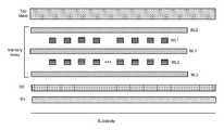
- FIG. 3which depicts various layers of an integrated circuit, shows the Memory Array positioned above the Substrate.
- the Memory Arrayincludes bit line layers BL 0 , BL 1 and BL 2 , and word line layers WL 0 and WL 1 . In other embodiments, additional bit line and word line layers can also be implemented.
- An integrated circuit implementing a semiconductor memory systemalso includes multiple metal layers used for routing signals between different components of the support circuitry, and between the supporting circuitry and the bit lines and word lines. These metal layers are arranged above the support circuitry that is implemented on the surface of the Substrate and below the Memory Array.
- FIG. 3shows two metal layers R 1 and R 2 used for routing; however, other embodiments can include more or less than two metal layers. In one example, these metal layers R 1 and R 2 are formed of Tungsten (about 1.5 ohm/square), which has both a relatively high resistance and high capacitance.
- FIG. 3shows one such metal layer above the memory array, labeled as the Top Metal layer.
- the top metal layeris formed of aluminum or copper (about 0.05 ohm/square), which has a smaller resistance and capacitance than layers R 1 and R 2 .
- Metals layers R 1 and R 2are not implemented using the same materials as used for the Top Metal because the metal used for R 1 and R 2 needs to withstand the processing steps for fabricating the memory array on top of R 1 and R 2 .
- Viascan be added to make connections between adjacent metal layers.
- Ziascan be added to make connections between layers that are not adjacent.
- a ziais a multi-layer via and can connect more than 2 layers (in which case the zia looks like a staircase).
- FIG. 4shows a logical view of memory array 102 divided into bays (e.g., Bay 0 , Bay 1 , . . . Bay N). The number of bays can be different for different implementations. Some embodiments may use only one bay.
- FIG. 5shows one bay (e.g., Bay 0 ) divided into blocks (Block 0 -Block 15 ). In one embodiment, there are 16 blocks in a bay. However, other embodiments can use different numbers of blocks.
- a sub-array or blockis a contiguous group of memory cells having contiguous word and bit lines generally unbroken by decoders, drivers, sense amplifiers, and input/output circuits. This is done for any of a variety of reasons. For example, the signal delays traversing down word lines and bit lines which arise from the resistance and the capacitance of such lines (i.e., the RC delays) may be very significant in a large array. These RC delays may be reduced by subdividing a larger array into a group of smaller sub-arrays so that the length of each word line and/or each bit line is reduced.
- the power associated with accessing a group of memory cellsmay dictate an upper limit to the number of memory cells which may be accessed simultaneously during a given memory cycle. Consequently, a large memory array is frequently subdivided into smaller sub-arrays to decrease the number of memory cells which are simultaneously accessed.
- An integrated circuitmay include one or more than one memory array.
- FIG. 5shows a subset of the Bit Lines for Block 0 .
- the substrateis wider than the memory array; therefore, portions of the Column Control Circuitry 110 can protrude out from under the memory array to facilitate connections using zias and vias to R 1 , R 2 , Top Metal, and the bit lines.
- Column Control Circuitry 110(including decoders and sense amplifiers) is divided into two sets of circuits, with each set of circuits being located on opposite sides (e.g.
- each blockthere are two sense amplifiers located below each block, for example, on the surface of the substrate.
- One of the two sense amplifiersare for bit lines that connect to Column Control Circuitry 110 on side A and the other sense amplifier is for bit lines that connect to Column Control Circuitry 110 on side B.
- one property of a bayis that all of the blocks in the bay share the same 32 sense amplifiers. That means that 32 memory cells in a bay can be simultaneously selected for programming or reading.
- the memory systemmust include circuits for selecting the 32 memory cells and lines for routing signals between the 32 selected memory cells and the sense amplifiers.
- a sectional data line schemecan be used. Local data lines are provided for each section, where a section can include one, two, four, etc. blocks. Selection circuits are used to connect the local data lines to the appropriate bit lines. Sense amplifier outputs are provided to global data lines across all bays. Selection circuits are used to connect the global data lines to the appropriate local data lines.
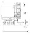
- FIG. 6is a schematic diagram that depicts a portion of the routing signals and selection circuits for one embodiment of Column Control Circuitry 110 that implements a sectional data line scheme.
- Each blockhas 64 columns of selection circuits 300 for electrically connecting bit lines to sense amplifiers on one side of the array (e.g. side A of FIG. 5 ) and 64 columns of selection circuits for connecting to bit lines to sense amplifiers on the other side of the array (e.g. side B of FIG. 5 ).
- FIG. 6only shows the 64 columns of selection circuits 300 for connecting to side B.
- the three dimensional memory arrayincludes four layers, with 1024 bit lines per layers. Other arrangements of the decoding circuits, bit lines and layers can also be used.
- each blockhas its own set of local data lines.
- block 0includes SELB 0 ⁇ 31:0>
- block 1includes SELB 1 ⁇ 31:0>
- . . . block 15includes SELB 15 ⁇ 31:0>.
- the local data lines SELB 0 ⁇ 31:0>, SELB 1 ⁇ 31:0>, . . . SELB 15 ⁇ 31:0>are implemented in metal layer R 1 under their respective block, and only run the width of the respective block.
- Selection circuits 300 for a particular columnare used to selectively connect the 32 bit lines for that same column to 32 respective local data lines (SELB 0 ⁇ 31:0>, SELB 1 ⁇ 31:0>, .
- each of the selection circuits 300receives a selection signal CD from column decoders 112 and a bit line connection from one of the 32 bit lines associated with the column. Based on the selection input from column decoder 112 , the selection circuit 300 will connect or disconnect the bit line to a respective one of the local data lines (e.g., SELB 0 ⁇ 31:0>, SELB 1 ⁇ 31:0>, . . . SELB 15 ⁇ 31:0>).
- the local data linese.g., SELB 0 ⁇ 31:0>, SELB 1 ⁇ 31:0>, . . . SELB 15 ⁇ 31:0>.
- FIG. 7is a schematic diagram showing the details of the selection circuits 300 .
- Selection circuit 302includes terminals A, B and C.
- the schematic diagram of FIG. 7also shows terminals A, B and C.
- Terminal Ais connected to column decoder 112 so that column decoder 112 can send a selection signal CD to control selection circuit 302 .
- Terminal Bis connected to a respective bit line.
- Terminal Cis connected to a respective local data line (e.g., one of SELB 0 ⁇ 31:0>, SELB 1 ⁇ 31:0>, . . . or SELB 15 ⁇ 31:0>).
- FIG. 1one of SELB 0 ⁇ 31:0>, SELB 1 ⁇ 31:0>, . . . or SELB 15 ⁇ 31:0>.
- FIG. 7also shows a terminal D, which is a global line for unselected bit lines.
- FIG. 6does not show the connection to all of the terminal D's of the selection circuits 300 ; however, one skilled in the art would understand that all of the terminal D's are connected to a common unselected bit line signal value.
- the selection circuitselectrically connect a bit line to a local data line so that the bit line can electrically communicate with the local data line.
- the selection circuitis configured to not electrically connect a bit line to a local data line, then the bit line cannot communicate with the local data line despite that both the bit line and data line are still physically connected to the selection circuit.
- the selection circuitseach include two connected transistors 584 and 586 and capacitor 588 .
- Capacitor 588is not an actual physical capacitor in the circuit. Instead, capacitor 588 represents the source-to-well parasitic capacitance.
- Terminal Aconnects the column decoder 112 to the gates of transistors 584 and 586 .
- the bit line at Terminal Bwill be in communication with the respective local data line (e.g., one of SELB 0 ⁇ 31:0>, SELB 1 ⁇ 31:0>, . . . or SELB 15 ⁇ 31:0>) at Terminal C or the unselected bit line signal at terminal D.
- Each of the selection circuits 300will be fabricated on the surface of the substrate with connections to bit lines using zias and connections to column decoders 112 , local data lines and unselected bit line signals using metal layers R 1 and/or R 2 .
- column decoders 112choose one column and send that chosen column a selection indication on the appropriate selection signal CD so that the chosen column connects the respective 32 bit lines to the local data lines (SELB 0 ⁇ 31:0>, SELB 1 ⁇ 31:0>, . . . or SELB 15 ⁇ 31:0>).
- Each blockhas its own set of sixteen 2:1 multiplexers (MUX) that are associated with the block and located on the substrate below the block.
- Each set of 32 local data lines(SELB 0 ⁇ 31:0>, SELB 1 ⁇ 31:0>, . . . or SELB 15 ⁇ 31:0>) are connected to a set of sixteen 2:1 multiplexers (MUX) for that respective block.
- the first multiplexerreceives SELB 0 ⁇ 0> and SELB 0 ⁇ 16>
- the second multiplexerreceives SELB 0 ⁇ 1> and SELB 0 ⁇ 17>
- Each of the multiplexersreceives a selection signal (e.g., signal S) from column decoders 112 so that 16 of the 32 local data lines are selected.
- the same selection signal Sis provided to all of the multiplexers (MUX) for a block (or bay) so that either (for example) SELB 0 ⁇ 15:0> are selected or SELB 0 ⁇ 16:31> are selected.
- the multiplexersinclude the ability to bias the unselected SELB.
- the sixteen selected local data linesare connected to global data lines GSELB[15:0].
- SELB 0 ⁇ 0>is connected to GSELB[0]
- SELB 0 ⁇ 1>is connected to GSELB[1], etc.
- SELB 0 ⁇ 16>is connected to GSELB[0]
- SELB 0 ⁇ 17>is connected to GSELB[1], etc.
- the global data lines GSELB[15:0]are implemented in Top Metal and connections between global data lines GSELB[15:0] and multiplexers (MUX) are made using zias (or vias).
- the global data lines GSELB[15:0]run across the entire Bay, with each BAY having its own set of global data lines. To reduce coupling between global data lines, various forms of Top Metal isolation can be used.
- Each of the global data lines GSELB[15:0]are connected to one of the sense amplifiers.
- the output Sense-Amp 0 of the sense amplifier located underneath block 0is connected to GSELB[0]
- the output Sense-Amp 1 of the sense amplifier located underneath block 1is connected to GSELB[1], . . .
- the output Sense-Amp 15 of the sense amplifier located underneath block 15is connected to GSELB[15].
- the output of a particular sense amplifieris connected to a global data line, then to a local data line by way of a multiplexer, and then to a bit line by way of a selection circuit.
- Top Metalhas significantly less resistance than metal layers R 1 and R 2 , the signal path from the sense amplifiers to the memory cells has a lower resistance. Capacitance is also reduced because the number of transistors that are “off” and are touched by the decoding line is reduced by almost 1/16 (previously all transistors in a bay were connected, now only the ones in a block). The total parasitic capacitance of the bit line drivers (source-to-well parasitic cap) is reduced by having a sectional data-line, by reducing number of bit line drives for each data-line (SELB).
- FIG. 6only shows the connection paths to sense amplifiers on one side (e.g., side B) of the blocks.
- a selected blockis associated with 64 selected bit lines that are connected to 64 local data lines, for which 32 multiplexers choose 32 local data lines to connect to 32 global data lines.
- the 32 global data linesare connected to 32 sense amplifiers associated with that particular bay.
- the choice of selecting 16 blocks in a bay, 64 bit lines in a column, using 64 local data lines, and 32 global data linesis for one set of embodiments. In other embodiments, different numbers of each item can be used. Additionally, the number of local data lines can be non-binary (like e.g., 48 or 96).
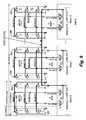
- FIG. 8provides an example of an embodiment where sets of local data lines are each shared by two blocks.
- FIG. 9provides an example of another embodiment where sets of local data lines are each shared by four blocks. In other embodiments, other numbers of blocks can share a set of local data lines.
- FIG. 8shows sixteen blocks that comprise a bay. Like FIG. 6 , FIG. 8 only shows the routing signals and selection circuits for connection to one side (e.g. side B).
- a set of data linesare shared by two blocks. For example, SELBA ⁇ 31:0> are shared by block 0 and block 1 , SELBB ⁇ 31:0> (not depicted) are shared by block 2 and block 3 , . . . and SELBH ⁇ 31:0> are shared by block 14 and block 15 .
- Each set of local data linesare implemented in metal layer R 1 and/or metal layer R 2 in the space below the associated blocks. For example, SELBA ⁇ 31:0> are implemented below block 0 and block 1 .
- FIG. 8depicts 64 columns for each block, with each column including 32 selection circuits 300 for selecting 32 bit lines to be connected to the local data lines.
- the local data linesare connected to sixteen multiplexers (MUX). Eight of the sixteen multiplexers are associated with and located below a first of the two blocks and the other eight multiplexers are associated with and located below the second of the two blocks. For example, sixteen of the SELBA lines are connected to multiplexers (MUX) bellow block 0 and sixteen of the SELBA lines are connected to multiplexers (MUX) bellow block 1 . In response to a selection signal from column decoders 112 , sixteen of the thirty two local data lines are connected to the global data lines GSELB[15:0].
- Each of the global data lines GSELB[15:0]are connected to one of the sense amplifiers.
- the output Sense-Amp 0 of the sense amplifier located underneath block 0is connected to GSELB[0]
- the output Sense-Amp 1 of the sense amplifier located underneath block 1is connected to GSELB[1], . . .
- the output Sense-Amp 15 of the sense amplifier located underneath block 15is connected to GSELB[15].
- the output of a particular sense amplifieris connected to a global data line, then to a local data line by way of a multiplexer, and then to a bit line by way of a selection circuit.
- FIG. 8only shows the connection paths to sense amplifiers on one side (e.g., side B) of the blocks.
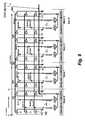
- FIG. 9depicts an embodiment where four blocks share a set of local data lines. Therefore, each bay (which includes sixteen blocks) would have four sets of local data lines that can be selectively connected to one set of global data lines for that bay. For ease of viewing, FIG. 9 only depicts four blocks: block 0 , block 1 , block 2 and block 3 , all of which share local data lines SELB ⁇ 0:32>.
- the local data lines SELB ⁇ 0:32>are implemented in metal layer R 1 or metal layer R 2 underneath blocks 0 - 3 .
- FIG. 9only shows the routing signals and selection circuits for connection to one side (e.g. side B).
- FIG. 9depicts 64 columns for each block, with each column including 32 selection circuits 300 for selecting 32 bit lines to be connected to the local data lines SELB.
- the local data linesare connected to sixteen multiplexers (MUX). Four of the sixteen multiplexers are associated with and located below each of the four blocks. For example, eight of the SELB lines are connected to multiplexers (MUX) below block 0 , eight of the SELB lines are connected to multiplexers (MUX) bellow block 1 , eight of the SELB lines are connected to multiplexers (MUX) bellow block 2 and eight of the SELB lines are connected to multiplexers (MUX) bellow block 3 .
- sixteen of the thirty two local data lines SELB ⁇ 31:0>are connected to the global data lines GSELB[15:0].
- Each of the global data lines GSELB[15:0]are connected to one of the sense amplifiers.
- the output Sense-Amp 0 of the sense amplifier located underneath block 0is connected to GSELB[0]
- the output Sense-Amp 1 of the sense amplifier located underneath block 1is connected to GSELB[1], . . .
- the output Sense-Amp 15 of the sense amplifier located underneath block 15is connected to GSELB[15].
- the output of a particular sense amplifieris connected to a global data line, then to a local data line by way of a multiplexer, and then to a bit line by way of a selection circuit.
- FIG. 9only shows the connection paths to sense amplifiers on one side (e.g., side B) of the blocks.
- the number of multiplexers and the number of signal lines to and from the multiplexersis reduced.
- eight, sixteen or other numbers of blockscan share a set of local data lines.
- the sense amplifieris sensing the selected memory cell during read operations by biasing the selected bit line to a higher voltage (e.g., 1.5 v).
- the selected word lineis biased to lower voltage (e.g., 0 v).
- the unselected word linesare biased at the same voltage as the selected bit-lines (e.g., 1.5 v).
- the unselected bit linescan be biased at the same voltage as selected bit-lines (e.g. 0 v).
- the memory arrayis also forward biased, which is similar to a read operation.
- the main differenceis the voltage range.
- the selected bit lineis required to be biased at the highest voltage: VWR (e.g., 8 v in “FORM”).
- the selected word-lineis at VSS.
- All unselected bit linesare biased at VUB (e.g., 0.7 v).
- All un-selected word-lineare biased at VUX (e.g., 7.5 v in “FORM”).
- the voltage range for SET and RESET operationsis 2-5 volts.
- the SET operationputs the reversible resistance-switching material in a low resistance state
- the RESET operationputs the reversible resistance-switching material in a high resistance state
- the FORM operationis the first SET operation (which requires a higher voltage than subsequent SET operations).
- Other schemescan also be used.
- the bit line driver circuitsare designed to pass selected bit line voltages through a PMOS transistor, as depicted in FIG. 7 (see transistor 584 ). It is proposed that the voltage driven during a read operation be lower than in the past. This creates an issue because the PMOS transistor (e.g., transistor 584 of FIG. 7 ) at the selected bit line driver (e.g. selection circuit) cannot deliver enough READ current (e.g. 1 uA) with the gate biased at VSS (0 v).
- Another disadvantage of connecting the local data lines to the selected bit-lineis the noise of N-well biased voltage (VUX) coupling to the sense amplifier output node. There is more than 4K of unselected bit-line drivers, which may couple enough noise (from VUX) to the sense amplifier output to cause a sensing error during read operations. This coupling happens through the parasitic capacitance of the bit line driver.
- FIG. 10shows four memory cells H, F, S, U (of the many memory cells) from a three dimensional memory array.
- memory cells Sis selected for a memory operation (read or program).
- FIG. 10shows two word line drivers (WL-Drivers) and two bit line drivers (BL-Drivers).
- FIG. 10provides bit line driver/selection circuit 310 to replace selection circuit 300 described above.
- Selection circuit 310connects the relevant selected bit line to a first local data line SELB through a PMOS transistor 320 during a programming operation (PROG) and connects the relevant selected bit line to a second local data line SELBN through a NMOS transistor 322 during a read operation (READ).
- PROGprogramming operation
- READread operation
- An extra NMOS transistor 324is added to the selection circuit 310 between the bit line and the unselected bit line voltage.
- the gate signal XCSEL of transistor 324is the reverse logic of PMOS transistor 320 during a read operation.
- CSELgate of transistors 320 and 322
- the sense amplifier output (SELBN)is connected to the selected bit line through NMOS transistor 322 .
- the maximum voltage(e.g., 2-8 v) should be able to be passed to the selected bit line.
- the sense amplifier outputis connected to the source of the PMOS transistor 320 (labeled SELB).
- the sense amplifier output voltage VWR(e.g., 6 volts) is applied on the selected bit line through the PMOS transistor 320 .
- FIG. 11depicts the routing signals and selection circuits for one block of a bay that has been adapted to utilize the scheme depicted in FIG. 10 .
- each block (or pair of blocks, or other group of blocks)is provided with two sets of local data lines: SELB and SELBN.
- block 0 depicted in FIG. 11has local data lines SELB ⁇ 31:0> and SELBN ⁇ 31:0>.
- the set of data lines SELB ⁇ 31:0>are used to drive voltages for selected bit lines during programming operations.
- the set of data lines SELBN ⁇ 31:0>are used to drive voltages for selected bit lines during read operations.
- each blockOn the substrate, below each block, are a set of sixteen 4:1 multiplexers 380 .
- Two of the inputs to each multiplexer 380are two of the local data lines SELB and two other inputs to each multiplexer 380 are two of the local data lines SELBN.
- a first (leftmost) multiplexer depicted in FIG. 11receives SELB ⁇ 0>, SELB ⁇ 16>, SELBN ⁇ 0>, and SELBN ⁇ 16>.
- Each multiplexer 320receives a selection signal from column control circuitry 110 to selectively connect one of the four local data lines to the associated global data lines. Sixteen of the sixty four local data lines provided to the multiplexers 380 are connected to GSELB[15:0] by multiplexers 380 .
- the selection signal from column control circuitry 110causes the set of sixteen multiplexers to select either SELB ⁇ 15:0>, SELB ⁇ 31:16>, SELBN ⁇ 15:0> or SELBN ⁇ 31:16>.
- FIG. 11only shows the connection paths to sense amplifiers on one side (e.g., side B) of block 0 .
- FIG. 12Ais a schematic of one example of multiplexer 380 .
- the schematicshows four NAND gates ( 402 , 404 , 406 and 408 ), sixteen transistors ( 420 , 422 , 424 , 426 , 428 , 430 , 432 , 434 , 436 , 438 , 440 , 442 , 444 , 446 , 448 and 450 ) and four inverters ( 460 , 462 , 464 and 466 ).
- FIG. 12Bis a table explaining the operation of the circuit of FIG. 12A .
- one of the four local data lines(SELB[i], SELB[j], SELBN[i] and SELBN[j]) can be selectively connected to the global data lines GSELB[i].
- FIG. 12Ashows NAND gate 402 receiving MAD[0], READ and XDIS and providing an output to transistor 420 , transistor 422 and inverter 460 .
- the output of inverter 460is provided to transistor 426 .
- Transistor 420is also connected to GSELB[i] and SELBN[i].
- Transistor 422is also connected to SELBN[i] and transistor 424 .
- Transistor 424is also connected to VUB and XDIS.
- Transistor 426is also connected to SELBN[i] and GSELB[i].
- NAND gate 404receives MAD[1], READ and XDIS and provides an output to transistor 428 , transistor 430 and inverter 462 .
- the output of inverter 462is provided to transistor 434 .
- Transistor 428is also connected to GSELB[i] and SELBN[j].
- Transistor 430is also connected to SELBN[i] and transistor 432 .
- Transistor 432is also connected to VUB and XDIS.
- Transistor 434is also connected to SELBN[i ] and GSELB[i].
- NAND gate 406receives MAD[0], XREAD and XDIS and provides an output to transistor 436 , transistor 438 and inverter 464 .
- the output of inverter 464is provided to transistor 42 .
- Transistor 436is also connected to GSELB[i] and SELB[i].
- Transistor 438is also connected to SELB[i] and transistor 440 .
- Transistor 440is also connected to VUB and XDIS.
- Transistor 442is also connected to SELB[i] and GSELB[i].
- NAND gate 408receives MAD[1], XREAD and XDIS and provides an output to transistor 444 , transistor 446 and inverter 466 .
- the output of inverter 466is provided to transistor 450 .
- Transistor 444is also connected to GSELB[i] and SELB[i].
- Transistor 446is also connected to SELB[i ] and transistor 448 .
- Transistor 448is also connected to VUB and XDIS.
- Transistor 450is also connected to SELBN[i] and GSELB[i].
- FIG. 13is a flow chart describing the operation of the decoding and selection circuits described herein.
- one bayis selected. In some embodiments, it may be possible to select more than one bay for simultaneous operations.
- a block within the selected bayis selected for a memory operation.
- the appropriate word line(s)is/are selected.
- a subset of the local data linesis selected using the multiplexers described above and, thereby, connected to the global data lines for the bay. These global data lines are in communication with the appropriate sense amplifiers or other relevant circuits.
- step 610one of the columns within the selected block is selected and the bit lines for that column are connected to the appropriate set of local data lines, as discussed above.
- step 612the appropriate signals are driven on the selected bit lines, selected word line(s), unselected bit lines and unselected word lines.
- step 614the desired read or program operation(s) is/are performed, including reporting the results (data read or success/failure of programming) to a host device that is in communication with the memory system. These steps can also be performed in other orders. The exact scheme for programming or reading depends on the type of memory cell used. The technology described herein can be used with many different types of memory cells and memory architectures.
Landscapes
- Semiconductor Memories (AREA)
- Dram (AREA)
Abstract
Description
Claims (19)
Priority Applications (11)
| Application Number | Priority Date | Filing Date | Title |
|---|---|---|---|
| US12/410,648US8130528B2 (en) | 2008-08-25 | 2009-03-25 | Memory system with sectional data lines |
| AT09790573TATE545134T1 (en) | 2008-08-25 | 2009-07-17 | STORAGE SYSTEM WITH SECTIONAL DATA LINES |
| CN200980133212.4ACN102132352B (en) | 2008-08-25 | 2009-07-17 | Memory system with sectional data lines |
| JP2011525038AJP5318211B2 (en) | 2008-08-25 | 2009-07-17 | Memory system having segmented data lines |
| KR1020117007003AKR101573509B1 (en) | 2008-08-25 | 2009-07-17 | Memory system with sectional data lines |
| EP09790573AEP2321826B1 (en) | 2008-08-25 | 2009-07-17 | Memory system with sectional data lines |
| PCT/US2009/050970WO2010024982A1 (en) | 2008-08-25 | 2009-07-17 | Memory system with sectional data lines |
| TW098126194ATWI427642B (en) | 2008-08-25 | 2009-08-04 | Memory system with sectional data lines |
| US13/079,613US8358528B2 (en) | 2008-08-25 | 2011-04-04 | Memory system with sectional data lines |
| US13/362,311US8913413B2 (en) | 2008-08-25 | 2012-01-31 | Memory system with sectional data lines |
| US13/362,320US8982597B2 (en) | 2008-08-25 | 2012-01-31 | Memory system with sectional data lines |
Applications Claiming Priority (2)
| Application Number | Priority Date | Filing Date | Title |
|---|---|---|---|
| US9172008P | 2008-08-25 | 2008-08-25 | |
| US12/410,648US8130528B2 (en) | 2008-08-25 | 2009-03-25 | Memory system with sectional data lines |
Related Child Applications (3)
| Application Number | Title | Priority Date | Filing Date |
|---|---|---|---|
| US13/079,613ContinuationUS8358528B2 (en) | 2008-08-25 | 2011-04-04 | Memory system with sectional data lines |
| US13/362,311DivisionUS8913413B2 (en) | 2008-08-25 | 2012-01-31 | Memory system with sectional data lines |
| US13/362,320ContinuationUS8982597B2 (en) | 2008-08-25 | 2012-01-31 | Memory system with sectional data lines |
Publications (2)
| Publication Number | Publication Date |
|---|---|
| US20100046267A1 US20100046267A1 (en) | 2010-02-25 |
| US8130528B2true US8130528B2 (en) | 2012-03-06 |
Family
ID=41696239
Family Applications (4)
| Application Number | Title | Priority Date | Filing Date |
|---|---|---|---|
| US12/410,648Active2029-05-05US8130528B2 (en) | 2008-08-25 | 2009-03-25 | Memory system with sectional data lines |
| US13/079,613ActiveUS8358528B2 (en) | 2008-08-25 | 2011-04-04 | Memory system with sectional data lines |
| US13/362,320ActiveUS8982597B2 (en) | 2008-08-25 | 2012-01-31 | Memory system with sectional data lines |
| US13/362,311ActiveUS8913413B2 (en) | 2008-08-25 | 2012-01-31 | Memory system with sectional data lines |
Family Applications After (3)
| Application Number | Title | Priority Date | Filing Date |
|---|---|---|---|
| US13/079,613ActiveUS8358528B2 (en) | 2008-08-25 | 2011-04-04 | Memory system with sectional data lines |
| US13/362,320ActiveUS8982597B2 (en) | 2008-08-25 | 2012-01-31 | Memory system with sectional data lines |
| US13/362,311ActiveUS8913413B2 (en) | 2008-08-25 | 2012-01-31 | Memory system with sectional data lines |
Country Status (8)
| Country | Link |
|---|---|
| US (4) | US8130528B2 (en) |
| EP (1) | EP2321826B1 (en) |
| JP (1) | JP5318211B2 (en) |
| KR (1) | KR101573509B1 (en) |
| CN (1) | CN102132352B (en) |
| AT (1) | ATE545134T1 (en) |
| TW (1) | TWI427642B (en) |
| WO (1) | WO2010024982A1 (en) |
Cited By (6)
| Publication number | Priority date | Publication date | Assignee | Title |
|---|---|---|---|---|
| US20120051229A1 (en)* | 2010-08-30 | 2012-03-01 | Technische Universitaet Berlin | Virtualization and replay-based system for network debugging |
| US20130003484A1 (en)* | 2011-06-29 | 2013-01-03 | Stmicroelectronics (Crolles 2) Sas | Partial write on a low power memory architecture |
| US8638586B2 (en) | 2009-04-20 | 2014-01-28 | Sandisk 3D Llc | Memory system with data line switching scheme |
| US8780651B2 (en) | 2008-10-06 | 2014-07-15 | Sandisk 3D Llc | Continuous programming of non-volatile memory |
| US8913413B2 (en) | 2008-08-25 | 2014-12-16 | Sandisk 3D Llc | Memory system with sectional data lines |
| US9202533B2 (en) | 2013-10-09 | 2015-12-01 | Kabushiki Kaisha Toshiba | Nonvolatile semiconductor memory device changing the number of selected bits and/or the number of selected bays at data write operation |
Families Citing this family (64)
| Publication number | Priority date | Publication date | Assignee | Title |
|---|---|---|---|---|
| US20100157647A1 (en)* | 2008-12-19 | 2010-06-24 | Unity Semiconductor Corporation | Memory access circuits and layout of the same for cross-point memory arrays |
| WO2011015970A1 (en)* | 2009-08-04 | 2011-02-10 | Axxana (Israel) Ltd. | Data gap management in a remote data mirroring system |
| JP5289353B2 (en)* | 2010-02-05 | 2013-09-11 | 株式会社東芝 | Semiconductor memory device |
| US9030859B2 (en) | 2010-12-14 | 2015-05-12 | Sandisk 3D Llc | Three dimensional non-volatile storage with dual layers of select devices |
| US8553476B2 (en) | 2011-03-03 | 2013-10-08 | Sandisk 3D Llc | Three dimensional memory system with page of data across word lines |
| US8374051B2 (en)* | 2011-03-03 | 2013-02-12 | Sandisk 3D Llc | Three dimensional memory system with column pipeline |
| US9053766B2 (en)* | 2011-03-03 | 2015-06-09 | Sandisk 3D, Llc | Three dimensional memory system with intelligent select circuit |
| US8699293B2 (en) | 2011-04-27 | 2014-04-15 | Sandisk 3D Llc | Non-volatile storage system with dual block programming |
| US8860117B2 (en) | 2011-04-28 | 2014-10-14 | Micron Technology, Inc. | Semiconductor apparatus with multiple tiers of memory cells with peripheral transistors, and methods |
| CN102332287B (en)* | 2011-07-15 | 2013-09-18 | 北京兆易创新科技股份有限公司 | Storage circuit and method for reading data by applying same |
| CN102332288B (en)* | 2011-07-15 | 2014-01-15 | 北京兆易创新科技股份有限公司 | Memory circuit and method for reading data by applying same |
| CN102332295B (en)* | 2011-07-15 | 2013-06-26 | 北京兆易创新科技股份有限公司 | Memory circuit and method for reading data by applying same |
| CN102332296B (en)* | 2011-07-15 | 2013-06-26 | 北京兆易创新科技股份有限公司 | Data reading method and data writing method of memory circuit |
| US9836340B2 (en)* | 2011-10-03 | 2017-12-05 | International Business Machines Corporation | Safe management of data storage using a volume manager |
| US9817733B2 (en)* | 2011-10-05 | 2017-11-14 | International Business Machines Corporation | Resource recovery for checkpoint-based high-availability in a virtualized environment |
| KR101916718B1 (en) | 2012-02-28 | 2018-11-09 | 삼성전자주식회사 | Nonvolatile memory device and memory management method thereof |
| US9171584B2 (en) | 2012-05-15 | 2015-10-27 | Sandisk 3D Llc | Three dimensional non-volatile storage with interleaved vertical select devices above and below vertical bit lines |
| WO2013184139A1 (en)* | 2012-06-08 | 2013-12-12 | Hewlett-Packard Development Company, L.P. | Accessing memory |
| US8964474B2 (en) | 2012-06-15 | 2015-02-24 | Micron Technology, Inc. | Architecture for 3-D NAND memory |
| US10037271B1 (en)* | 2012-06-27 | 2018-07-31 | Teradata Us, Inc. | Data-temperature-based control of buffer cache memory in a database system |
| MX364783B (en)* | 2012-11-20 | 2019-05-07 | Thstyme Bermuda Ltd | Solid state drive architectures. |
| US11037625B2 (en) | 2012-11-20 | 2021-06-15 | Thstyme Bermuda Limited | Solid state drive architectures |
| CN107093440B (en)* | 2012-12-27 | 2021-10-01 | 英特尔公司 | SRAM bit line and write assist apparatus and method for reducing dynamic power and peak current and dual input level shifter |
| WO2014138124A1 (en) | 2013-03-04 | 2014-09-12 | Sandisk 3D Llc | Vertical bit line non-volatile memory systems and methods of fabrication |
| US9165933B2 (en) | 2013-03-07 | 2015-10-20 | Sandisk 3D Llc | Vertical bit line TFT decoder for high voltage operation |
| US9778884B2 (en)* | 2013-03-13 | 2017-10-03 | Hewlett Packard Enterprise Development Lp | Virtual storage pool |
| US8947972B2 (en) | 2013-03-15 | 2015-02-03 | Sandisk 3D Llc | Dynamic address grouping for parallel programming in non-volatile memory |
| US8947944B2 (en) | 2013-03-15 | 2015-02-03 | Sandisk 3D Llc | Program cycle skip evaluation before write operations in non-volatile memory |
| US9201662B2 (en)* | 2013-03-29 | 2015-12-01 | Dell Products, Lp | System and method for pre-operating system memory map management to minimize operating system failures |
| US20140297953A1 (en)* | 2013-03-31 | 2014-10-02 | Microsoft Corporation | Removable Storage Device Identity and Configuration Information |
| US9836413B2 (en)* | 2013-04-03 | 2017-12-05 | International Business Machines Corporation | Maintaining cache consistency in a cache for cache eviction policies supporting dependencies |
| US9711225B2 (en) | 2013-10-16 | 2017-07-18 | Sandisk Technologies Llc | Regrouping and skipping cycles in non-volatile memory |
| US9824020B2 (en)* | 2013-12-30 | 2017-11-21 | Unisys Corporation | Systems and methods for memory management in a dynamic translation computer system |
| US11073986B2 (en)* | 2014-01-30 | 2021-07-27 | Hewlett Packard Enterprise Development Lp | Memory data versioning |
| WO2015116077A1 (en)* | 2014-01-30 | 2015-08-06 | Hewlett-Packard Development Company, L.P. | Access controlled memory region |
| US9362338B2 (en) | 2014-03-03 | 2016-06-07 | Sandisk Technologies Inc. | Vertical thin film transistors in non-volatile storage systems |
| US9379246B2 (en) | 2014-03-05 | 2016-06-28 | Sandisk Technologies Inc. | Vertical thin film transistor selection devices and methods of fabrication |
| US9627009B2 (en) | 2014-07-25 | 2017-04-18 | Sandisk Technologies Llc | Interleaved grouped word lines for three dimensional non-volatile storage |
| TWI552162B (en)* | 2014-07-31 | 2016-10-01 | Zhi-Cheng Xiao | Low power memory |
| WO2016095156A1 (en)* | 2014-12-18 | 2016-06-23 | Intel Corporation | Translation cache closure and persistent snapshot in dynamic code generating system software |
| US9824026B2 (en)* | 2014-12-23 | 2017-11-21 | Intel Corporation | Apparatus and method for managing a virtual graphics processor unit (VGPU) |
| US9564215B2 (en) | 2015-02-11 | 2017-02-07 | Sandisk Technologies Llc | Independent sense amplifier addressing and quota sharing in non-volatile memory |
| US9450023B1 (en) | 2015-04-08 | 2016-09-20 | Sandisk Technologies Llc | Vertical bit line non-volatile memory with recessed word lines |
| US9875037B2 (en)* | 2015-06-18 | 2018-01-23 | International Business Machines Corporation | Implementing multiple raid level configurations in a data storage device |
| US20160189755A1 (en) | 2015-08-30 | 2016-06-30 | Chih-Cheng Hsiao | Low power memory device |
| US10403338B2 (en) | 2015-08-30 | 2019-09-03 | Chih-Cheng Hsiao | Low power memory device with column and row line switches for specific memory cells |
| US9760290B2 (en)* | 2015-09-25 | 2017-09-12 | International Business Machines Corporation | Smart volume manager for storage space usage optimization |
| US9946512B2 (en)* | 2015-09-25 | 2018-04-17 | International Business Machines Corporation | Adaptive radix external in-place radix sort |
| US9542980B1 (en)* | 2016-03-29 | 2017-01-10 | Nanya Technology Corp. | Sense amplifier with mini-gap architecture and parallel interconnect |
| US9921757B1 (en)* | 2016-03-31 | 2018-03-20 | EMC IP Holding Company LLC | Using an FPGA for integration with low-latency, non-volatile memory |
| US9679650B1 (en) | 2016-05-06 | 2017-06-13 | Micron Technology, Inc. | 3D NAND memory Z-decoder |
| US10126896B2 (en)* | 2016-06-28 | 2018-11-13 | Synaptics Incorporated | Selective receiver electrode scanning |
| US10296460B2 (en)* | 2016-06-29 | 2019-05-21 | Oracle International Corporation | Prefetch bandwidth throttling by dynamically adjusting miss buffer prefetch-dropping thresholds |
| EP3507806B1 (en) | 2016-08-31 | 2022-01-19 | Micron Technology, Inc. | Apparatuses and methods including ferroelectric memory and for accessing ferroelectric memory |
| CN206471121U (en)* | 2016-10-07 | 2017-09-05 | 芝奇国际实业股份有限公司 | memory device |
| KR20190051653A (en)* | 2017-11-07 | 2019-05-15 | 삼성전자주식회사 | Semiconductor memory device and data path configuration method thereof |
| US10923161B2 (en)* | 2018-01-18 | 2021-02-16 | Arm Limited | Bitcell wordline strapping circuitry |
| US11450381B2 (en) | 2019-08-21 | 2022-09-20 | Micron Technology, Inc. | Multi-deck memory device including buffer circuitry under array |
| US11417375B2 (en)* | 2019-12-17 | 2022-08-16 | Micron Technology, Inc. | Discharge current mitigation in a memory array |
| US11043500B1 (en)* | 2020-03-19 | 2021-06-22 | Micron Technology, Inc. | Integrated assemblies comprising twisted digit line configurations |
| US11309034B2 (en)* | 2020-07-15 | 2022-04-19 | Ferroelectric Memory Gmbh | Memory cell arrangement and methods thereof |
| US11915740B2 (en)* | 2022-03-03 | 2024-02-27 | Micron Technology, Inc. | Parallel access in a memory array |
| US20240161828A1 (en)* | 2022-11-14 | 2024-05-16 | Sandisk Technologies Llc | Non-volatile memory with sub-blocks |
| US20240347126A1 (en)* | 2023-04-11 | 2024-10-17 | Micron Technology, Inc. | Read pass voltage adjustment among multiple erase blocks coupled to a same string |
Citations (26)
| Publication number | Priority date | Publication date | Assignee | Title |
|---|---|---|---|---|
| US3983537A (en) | 1973-01-28 | 1976-09-28 | Hawker Siddeley Dynamics Limited | Reliability of random access memory systems |
| US5159572A (en)* | 1990-12-24 | 1992-10-27 | Motorola, Inc. | DRAM architecture having distributed address decoding and timing control |
| US5315541A (en) | 1992-07-24 | 1994-05-24 | Sundisk Corporation | Segmented column memory array |
| US5835396A (en) | 1996-10-17 | 1998-11-10 | Zhang; Guobiao | Three-dimensional read-only memory |
| US5915167A (en) | 1997-04-04 | 1999-06-22 | Elm Technology Corporation | Three dimensional structure memory |
| US5963465A (en) | 1997-12-12 | 1999-10-05 | Saifun Semiconductors, Ltd. | Symmetric segmented memory array architecture |
| US6034882A (en)* | 1998-11-16 | 2000-03-07 | Matrix Semiconductor, Inc. | Vertically stacked field programmable nonvolatile memory and method of fabrication |
| US6420215B1 (en) | 2000-04-28 | 2002-07-16 | Matrix Semiconductor, Inc. | Three-dimensional memory array and method of fabrication |
| EP1282134A2 (en) | 2001-08-02 | 2003-02-05 | STMicroelectronics, Inc. | Dual bank flash memory device and method |
| US6525953B1 (en) | 2001-08-13 | 2003-02-25 | Matrix Semiconductor, Inc. | Vertically-stacked, field-programmable, nonvolatile memory and method of fabrication |
| US6532172B2 (en) | 2001-05-31 | 2003-03-11 | Sandisk Corporation | Steering gate and bit line segmentation in non-volatile memories |
| US20040188714A1 (en) | 2003-03-31 | 2004-09-30 | Scheuerlein Roy E. | Three-dimensional memory device incorporating segmented bit line memory array |
| US6856541B2 (en) | 2001-09-21 | 2005-02-15 | Sandisk Corporation | Segmented metal bitlines |
| US6856572B2 (en) | 2000-04-28 | 2005-02-15 | Matrix Semiconductor, Inc. | Multi-headed decoder structure utilizing memory array line driver with dual purpose driver device |
| US6879505B2 (en) | 2003-03-31 | 2005-04-12 | Matrix Semiconductor, Inc. | Word line arrangement having multi-layer word line segments for three-dimensional memory array |
| US6951780B1 (en) | 2003-12-18 | 2005-10-04 | Matrix Semiconductor, Inc. | Selective oxidation of silicon in diode, TFT, and monolithic three dimensional memory arrays |
| US6952043B2 (en) | 2002-06-27 | 2005-10-04 | Matrix Semiconductor, Inc. | Electrically isolated pillars in active devices |
| US6952030B2 (en) | 2002-12-19 | 2005-10-04 | Matrix Semiconductor, Inc. | High-density three-dimensional memory cell |
| US7042765B2 (en) | 2004-08-06 | 2006-05-09 | Freescale Semiconductor, Inc. | Memory bit line segment isolation |
| US20060146608A1 (en) | 2004-12-30 | 2006-07-06 | Matrix Semiconductor, Inc. | Integrated circuit including memory array incorporating multiple types of NAND string structures |
| US20060146639A1 (en) | 2004-12-30 | 2006-07-06 | Matrix Semiconductor, Inc. | Apparatus and method for hierarchical decoding of dense memory arrays using multiple levels of multiple-headed decoders |
| US7081377B2 (en) | 2002-06-27 | 2006-07-25 | Sandisk 3D Llc | Three-dimensional memory |
| US20060250836A1 (en) | 2005-05-09 | 2006-11-09 | Matrix Semiconductor, Inc. | Rewriteable memory cell comprising a diode and a resistance-switching material |
| US20070190722A1 (en) | 2002-12-19 | 2007-08-16 | Herner S B | Method to form upward pointing p-i-n diodes having large and uniform current |
| US7359279B2 (en) | 2005-03-31 | 2008-04-15 | Sandisk 3D Llc | Integrated circuit memory array configuration including decoding compatibility with partial implementation of multiple memory layers |
| US20090296443A1 (en)* | 2008-05-28 | 2009-12-03 | Micron Technology, Inc. | Memory device having data paths |
Family Cites Families (96)
| Publication number | Priority date | Publication date | Assignee | Title |
|---|---|---|---|---|
| US5111071A (en) | 1989-10-19 | 1992-05-05 | Texas Instruments Incorporated | Threshold detection circuit |
| DE69222762T2 (en) | 1992-07-30 | 1998-02-12 | St Microelectronics Srl | Control part and error amplifier device with a circuit for measuring the voltage fluctuations related to a voltage setpoint |
| US5369614A (en) | 1992-10-12 | 1994-11-29 | Ricoh Company, Ltd. | Detecting amplifier with current mirror structure |
| US5623436A (en) | 1993-06-17 | 1997-04-22 | Information Storage Devices | Method and apparatus for adjustment and control of an iterative method of recording analog signals with on-chip trimming techniques |
| JP3205658B2 (en) | 1993-12-28 | 2001-09-04 | 新日本製鐵株式会社 | Reading method of semiconductor memory device |
| US5742787A (en) | 1995-04-10 | 1998-04-21 | Intel Corporation | Hardware reset of a write state machine for flash memory |
| KR100253868B1 (en) | 1995-11-13 | 2000-05-01 | 니시무로 타이죠 | Non-volatile semiconductor memory device |
| KR100244864B1 (en) | 1996-03-18 | 2000-03-02 | 니시무로 타이죠 | Non-volatile semiconductor memory |
| US5712815A (en) | 1996-04-22 | 1998-01-27 | Advanced Micro Devices, Inc. | Multiple bits per-cell flash EEPROM capable of concurrently programming and verifying memory cells and reference cells |
| US5675537A (en) | 1996-08-22 | 1997-10-07 | Advanced Micro Devices, Inc. | Erase method for page mode multiple bits-per-cell flash EEPROM |
| TW338165B (en) | 1996-09-09 | 1998-08-11 | Sony Co Ltd | Semiconductor nand type flash memory with incremental step pulse programming |
| US5847998A (en) | 1996-12-20 | 1998-12-08 | Advanced Micro Devices, Inc. | Non-volatile memory array that enables simultaneous read and write operations |
| US6809462B2 (en) | 2000-04-05 | 2004-10-26 | Sri International | Electroactive polymer sensors |
| US5841696A (en) | 1997-03-05 | 1998-11-24 | Advanced Micro Devices, Inc. | Non-volatile memory enabling simultaneous reading and writing by time multiplexing a decode path |
| JP3481817B2 (en) | 1997-04-07 | 2003-12-22 | 株式会社東芝 | Semiconductor storage device |
| US5959892A (en) | 1997-08-26 | 1999-09-28 | Macronix International Co., Ltd. | Apparatus and method for programming virtual ground EPROM array cell without disturbing adjacent cells |
| US5894437A (en) | 1998-01-23 | 1999-04-13 | Hyundai Elecronics America, Inc. | Concurrent read/write architecture for a flash memory |
| JP3344313B2 (en) | 1998-03-25 | 2002-11-11 | 日本電気株式会社 | Nonvolatile semiconductor memory device |
| US6141241A (en) | 1998-06-23 | 2000-10-31 | Energy Conversion Devices, Inc. | Universal memory element with systems employing same and apparatus and method for reading, writing and programming same |
| US5912839A (en) | 1998-06-23 | 1999-06-15 | Energy Conversion Devices, Inc. | Universal memory element and method of programming same |
| JP3999900B2 (en) | 1998-09-10 | 2007-10-31 | 株式会社東芝 | Nonvolatile semiconductor memory |
| US6214666B1 (en) | 1998-12-18 | 2001-04-10 | Vantis Corporation | Method of forming a non-volatile memory device |
| JP2000243086A (en) | 1998-12-24 | 2000-09-08 | Mitsubishi Electric Corp | Semiconductor storage device |
| US6157560A (en)* | 1999-01-25 | 2000-12-05 | Winbond Electronics Corporation | Memory array datapath architecture |
| KR100331847B1 (en) | 1999-06-29 | 2002-04-09 | 박종섭 | Circuit for holding threshold voltage of reference memory cell and method for holding threshold voltage thereby |
| JP2001015352A (en) | 1999-06-30 | 2001-01-19 | Mitsubishi Electric Corp | Transformer |
| US6091633A (en) | 1999-08-09 | 2000-07-18 | Sandisk Corporation | Memory array architecture utilizing global bit lines shared by multiple cells |
| JP2001067884A (en) | 1999-08-31 | 2001-03-16 | Hitachi Ltd | Nonvolatile semiconductor memory device |
| US6292048B1 (en) | 1999-11-11 | 2001-09-18 | Intel Corporation | Gate enhancement charge pump for low voltage power supply |
| TW587252B (en) | 2000-01-18 | 2004-05-11 | Hitachi Ltd | Semiconductor memory device and data processing device |
| US6426893B1 (en) | 2000-02-17 | 2002-07-30 | Sandisk Corporation | Flash eeprom system with simultaneous multiple data sector programming and storage of physical block characteristics in other designated blocks |
| JP3983969B2 (en) | 2000-03-08 | 2007-09-26 | 株式会社東芝 | Nonvolatile semiconductor memory device |
| US6301161B1 (en) | 2000-04-25 | 2001-10-09 | Winbond Electronics Corporation | Programming flash memory analog storage using coarse-and-fine sequence |
| US6567287B2 (en) | 2001-03-21 | 2003-05-20 | Matrix Semiconductor, Inc. | Memory device with row and column decoder circuits arranged in a checkerboard pattern under a plurality of memory arrays |
| US6331943B1 (en) | 2000-08-28 | 2001-12-18 | Motorola, Inc. | MTJ MRAM series-parallel architecture |
| US6529410B1 (en) | 2000-09-20 | 2003-03-04 | Advanced Micro Devices, Inc. | NAND array structure and method with buried layer |
| JP3922516B2 (en) | 2000-09-28 | 2007-05-30 | 株式会社ルネサステクノロジ | Nonvolatile memory and writing method of nonvolatile memory |
| US6587370B2 (en) | 2000-11-01 | 2003-07-01 | Canon Kabushiki Kaisha | Magnetic memory and information recording and reproducing method therefor |
| KR100385230B1 (en) | 2000-12-28 | 2003-05-27 | 삼성전자주식회사 | Method for programming a nonvolatile semiconductor memory device |
| US6574145B2 (en) | 2001-03-21 | 2003-06-03 | Matrix Semiconductor, Inc. | Memory device and method for sensing while programming a non-volatile memory cell |
| US6473332B1 (en) | 2001-04-04 | 2002-10-29 | The University Of Houston System | Electrically variable multi-state resistance computing |
| JP4907011B2 (en) | 2001-04-27 | 2012-03-28 | 株式会社半導体エネルギー研究所 | Nonvolatile memory, driving method thereof, and semiconductor device |
| US6529409B1 (en) | 2001-09-10 | 2003-03-04 | Silicon Storage Technology, Inc. | Integrated circuit for concurrent flash memory with uneven array architecture |
| US6879525B2 (en) | 2001-10-31 | 2005-04-12 | Hewlett-Packard Development Company, L.P. | Feedback write method for programmable memory |
| US6873538B2 (en) | 2001-12-20 | 2005-03-29 | Micron Technology, Inc. | Programmable conductor random access memory and a method for writing thereto |
| US6871257B2 (en) | 2002-02-22 | 2005-03-22 | Sandisk Corporation | Pipelined parallel programming operation in a non-volatile memory system |
| US6563369B1 (en) | 2002-03-26 | 2003-05-13 | Intel Corporation | Active current mirror circuit |
| US6940748B2 (en) | 2002-05-16 | 2005-09-06 | Micron Technology, Inc. | Stacked 1T-nMTJ MRAM structure |
| US6657889B1 (en) | 2002-06-28 | 2003-12-02 | Motorola, Inc. | Memory having write current ramp rate control |
| US6859382B2 (en) | 2002-08-02 | 2005-02-22 | Unity Semiconductor Corporation | Memory array of a non-volatile ram |
| US20040036103A1 (en) | 2002-08-20 | 2004-02-26 | Macronix International Co., Ltd. | Memory device and method of manufacturing the same |
| US6940744B2 (en) | 2002-10-31 | 2005-09-06 | Unity Semiconductor Corporation | Adaptive programming technique for a re-writable conductive memory device |
| JP4249992B2 (en) | 2002-12-04 | 2009-04-08 | シャープ株式会社 | Semiconductor memory device and memory cell writing and erasing method |
| US7005350B2 (en) | 2002-12-31 | 2006-02-28 | Matrix Semiconductor, Inc. | Method for fabricating programmable memory array structures incorporating series-connected transistor strings |
| DE10310163A1 (en) | 2003-03-08 | 2004-09-16 | Braun Gmbh | slide switches |
| US7706167B2 (en) | 2003-03-18 | 2010-04-27 | Kabushiki Kaisha Toshiba | Resistance change memory device |
| WO2004090984A1 (en) | 2003-04-03 | 2004-10-21 | Kabushiki Kaisha Toshiba | Phase change memory device |
| US7093062B2 (en) | 2003-04-10 | 2006-08-15 | Micron Technology, Inc. | Flash memory data bus for synchronous burst read page |
| FR2859041A1 (en) | 2003-08-18 | 2005-02-25 | St Microelectronics Sa | NON-VOLATILE MEMORY MEMORY CIRCUIT FOR IDENTIFICATION AND ASSOCIATED METHOD |
| US7369428B2 (en) | 2003-09-29 | 2008-05-06 | Samsung Electronics Co., Ltd. | Methods of operating a magnetic random access memory device and related devices and structures |
| US7068539B2 (en) | 2004-01-27 | 2006-06-27 | Sandisk Corporation | Charge packet metering for coarse/fine programming of non-volatile memory |
| US7307884B2 (en) | 2004-06-15 | 2007-12-11 | Sandisk Corporation | Concurrent programming of non-volatile memory |
| DE102004040750B4 (en) | 2004-08-23 | 2008-03-27 | Qimonda Ag | Memory cell arrangement with memory cells of the CBRAM type and method for programming the same |
| DE112004002973B4 (en) | 2004-09-30 | 2011-06-01 | Spansion LLC (n.d.Ges.d. Staates Delaware), Sunnyvale | Semiconductor device and method for writing data |
| KR100669342B1 (en) | 2004-12-21 | 2007-01-16 | 삼성전자주식회사 | How to Program Nand Flash Memory Devices |
| US7307268B2 (en) | 2005-01-19 | 2007-12-11 | Sandisk Corporation | Structure and method for biasing phase change memory array for reliable writing |
| JP4890016B2 (en) | 2005-03-16 | 2012-03-07 | ルネサスエレクトロニクス株式会社 | Nonvolatile semiconductor memory device |
| US7187585B2 (en) | 2005-04-05 | 2007-03-06 | Sandisk Corporation | Read operation for non-volatile storage that includes compensation for coupling |
| US7812404B2 (en) | 2005-05-09 | 2010-10-12 | Sandisk 3D Llc | Nonvolatile memory cell comprising a diode and a resistance-switching material |
| JP4282636B2 (en) | 2005-06-22 | 2009-06-24 | 株式会社東芝 | Nonvolatile semiconductor memory device and data writing method thereof |
| US7304888B2 (en) | 2005-07-01 | 2007-12-04 | Sandisk 3D Llc | Reverse-bias method for writing memory cells in a memory array |
| US7362604B2 (en) | 2005-07-11 | 2008-04-22 | Sandisk 3D Llc | Apparatus and method for programming an array of nonvolatile memory cells including switchable resistor memory elements |
| US7426128B2 (en) | 2005-07-11 | 2008-09-16 | Sandisk 3D Llc | Switchable resistive memory with opposite polarity write pulses |
| US7652922B2 (en) | 2005-09-30 | 2010-01-26 | Mosaid Technologies Incorporated | Multiple independent serial link memory |
| JP2007133927A (en)* | 2005-11-08 | 2007-05-31 | Toshiba Corp | Semiconductor memory device and control method thereof |
| US7499355B2 (en) | 2006-07-31 | 2009-03-03 | Sandisk 3D Llc | High bandwidth one time field-programmable memory |
| US7463546B2 (en) | 2006-07-31 | 2008-12-09 | Sandisk 3D Llc | Method for using a passive element memory array incorporating reversible polarity word line and bit line decoders |
| KR100755409B1 (en) | 2006-08-28 | 2007-09-04 | 삼성전자주식회사 | How to Program a Resistive Memory Device |
| US7443712B2 (en) | 2006-09-07 | 2008-10-28 | Spansion Llc | Memory erase management system |
| WO2008032394A1 (en)* | 2006-09-15 | 2008-03-20 | Renesas Technology Corp. | Semiconductor device |
| US7420850B2 (en) | 2006-10-24 | 2008-09-02 | Sandisk 3D Llc | Method for controlling current during programming of memory cells |
| US7391638B2 (en) | 2006-10-24 | 2008-06-24 | Sandisk 3D Llc | Memory device for protecting memory cells during programming |
| US7589989B2 (en) | 2006-10-24 | 2009-09-15 | Sandisk 3D Llc | Method for protecting memory cells during programming |
| US7539062B2 (en) | 2006-12-20 | 2009-05-26 | Micron Technology, Inc. | Interleaved memory program and verify method, device and system |
| KR100809339B1 (en) | 2006-12-20 | 2008-03-05 | 삼성전자주식회사 | Nonvolatile Memory Device Using Resistor and Driving Method Thereof |
| KR101348173B1 (en)* | 2007-05-25 | 2014-01-08 | 삼성전자주식회사 | Flash memory device, erase and program methods, and memory system including the same |
| CN101548336B (en) | 2007-06-22 | 2012-07-11 | 松下电器产业株式会社 | Resistance variable nonvolatile memory device |
| US7778064B2 (en) | 2007-11-07 | 2010-08-17 | Ovonyx, Inc. | Accessing a phase change memory |
| JP2009199695A (en) | 2008-02-25 | 2009-09-03 | Toshiba Corp | Resistance change memory device |
| US7869258B2 (en) | 2008-06-27 | 2011-01-11 | Sandisk 3D, Llc | Reverse set with current limit for non-volatile storage |
| US8111539B2 (en) | 2008-06-27 | 2012-02-07 | Sandisk 3D Llc | Smart detection circuit for writing to non-volatile storage |
| US8059447B2 (en) | 2008-06-27 | 2011-11-15 | Sandisk 3D Llc | Capacitive discharge method for writing to non-volatile memory |
| US7978507B2 (en) | 2008-06-27 | 2011-07-12 | Sandisk 3D, Llc | Pulse reset for non-volatile storage |
| US8130528B2 (en)* | 2008-08-25 | 2012-03-06 | Sandisk 3D Llc | Memory system with sectional data lines |
| US8027209B2 (en) | 2008-10-06 | 2011-09-27 | Sandisk 3D, Llc | Continuous programming of non-volatile memory |
| US8279650B2 (en) | 2009-04-20 | 2012-10-02 | Sandisk 3D Llc | Memory system with data line switching scheme |
- 2009
- 2009-03-25USUS12/410,648patent/US8130528B2/enactiveActive
- 2009-07-17CNCN200980133212.4Apatent/CN102132352B/enactiveActive
- 2009-07-17KRKR1020117007003Apatent/KR101573509B1/enactiveActive
- 2009-07-17JPJP2011525038Apatent/JP5318211B2/enactiveActive
- 2009-07-17WOPCT/US2009/050970patent/WO2010024982A1/enactiveApplication Filing
- 2009-07-17EPEP09790573Apatent/EP2321826B1/enactiveActive
- 2009-07-17ATAT09790573Tpatent/ATE545134T1/enactive
- 2009-08-04TWTW098126194Apatent/TWI427642B/ennot_activeIP Right Cessation
- 2011
- 2011-04-04USUS13/079,613patent/US8358528B2/enactiveActive
- 2012
- 2012-01-31USUS13/362,320patent/US8982597B2/enactiveActive
- 2012-01-31USUS13/362,311patent/US8913413B2/enactiveActive
Patent Citations (28)
| Publication number | Priority date | Publication date | Assignee | Title |
|---|---|---|---|---|
| US3983537A (en) | 1973-01-28 | 1976-09-28 | Hawker Siddeley Dynamics Limited | Reliability of random access memory systems |
| US5159572A (en)* | 1990-12-24 | 1992-10-27 | Motorola, Inc. | DRAM architecture having distributed address decoding and timing control |
| US5315541A (en) | 1992-07-24 | 1994-05-24 | Sundisk Corporation | Segmented column memory array |
| US5835396A (en) | 1996-10-17 | 1998-11-10 | Zhang; Guobiao | Three-dimensional read-only memory |
| US5915167A (en) | 1997-04-04 | 1999-06-22 | Elm Technology Corporation | Three dimensional structure memory |
| US5963465A (en) | 1997-12-12 | 1999-10-05 | Saifun Semiconductors, Ltd. | Symmetric segmented memory array architecture |
| US6034882A (en)* | 1998-11-16 | 2000-03-07 | Matrix Semiconductor, Inc. | Vertically stacked field programmable nonvolatile memory and method of fabrication |
| US6420215B1 (en) | 2000-04-28 | 2002-07-16 | Matrix Semiconductor, Inc. | Three-dimensional memory array and method of fabrication |
| US6856572B2 (en) | 2000-04-28 | 2005-02-15 | Matrix Semiconductor, Inc. | Multi-headed decoder structure utilizing memory array line driver with dual purpose driver device |
| US6532172B2 (en) | 2001-05-31 | 2003-03-11 | Sandisk Corporation | Steering gate and bit line segmentation in non-volatile memories |
| EP1282134A2 (en) | 2001-08-02 | 2003-02-05 | STMicroelectronics, Inc. | Dual bank flash memory device and method |
| US6525953B1 (en) | 2001-08-13 | 2003-02-25 | Matrix Semiconductor, Inc. | Vertically-stacked, field-programmable, nonvolatile memory and method of fabrication |
| US6856541B2 (en) | 2001-09-21 | 2005-02-15 | Sandisk Corporation | Segmented metal bitlines |
| US7081377B2 (en) | 2002-06-27 | 2006-07-25 | Sandisk 3D Llc | Three-dimensional memory |
| US6952043B2 (en) | 2002-06-27 | 2005-10-04 | Matrix Semiconductor, Inc. | Electrically isolated pillars in active devices |
| US20070190722A1 (en) | 2002-12-19 | 2007-08-16 | Herner S B | Method to form upward pointing p-i-n diodes having large and uniform current |
| US6952030B2 (en) | 2002-12-19 | 2005-10-04 | Matrix Semiconductor, Inc. | High-density three-dimensional memory cell |
| US20040188714A1 (en) | 2003-03-31 | 2004-09-30 | Scheuerlein Roy E. | Three-dimensional memory device incorporating segmented bit line memory array |
| US6879505B2 (en) | 2003-03-31 | 2005-04-12 | Matrix Semiconductor, Inc. | Word line arrangement having multi-layer word line segments for three-dimensional memory array |
| US20070263423A1 (en)* | 2003-03-31 | 2007-11-15 | Scheuerlein Roy E | Three-dimensional memory device incorporating segmented array line memory array |
| US6951780B1 (en) | 2003-12-18 | 2005-10-04 | Matrix Semiconductor, Inc. | Selective oxidation of silicon in diode, TFT, and monolithic three dimensional memory arrays |
| US7042765B2 (en) | 2004-08-06 | 2006-05-09 | Freescale Semiconductor, Inc. | Memory bit line segment isolation |
| US20060146608A1 (en) | 2004-12-30 | 2006-07-06 | Matrix Semiconductor, Inc. | Integrated circuit including memory array incorporating multiple types of NAND string structures |
| US20060146639A1 (en) | 2004-12-30 | 2006-07-06 | Matrix Semiconductor, Inc. | Apparatus and method for hierarchical decoding of dense memory arrays using multiple levels of multiple-headed decoders |
| US7286439B2 (en) | 2004-12-30 | 2007-10-23 | Sandisk 3D Llc | Apparatus and method for hierarchical decoding of dense memory arrays using multiple levels of multiple-headed decoders |
| US7359279B2 (en) | 2005-03-31 | 2008-04-15 | Sandisk 3D Llc | Integrated circuit memory array configuration including decoding compatibility with partial implementation of multiple memory layers |
| US20060250836A1 (en) | 2005-05-09 | 2006-11-09 | Matrix Semiconductor, Inc. | Rewriteable memory cell comprising a diode and a resistance-switching material |
| US20090296443A1 (en)* | 2008-05-28 | 2009-12-03 | Micron Technology, Inc. | Memory device having data paths |
Non-Patent Citations (3)
| Title |
|---|
| PCT International Search Report dated Sep. 29, 2009, PCT Appl. PCT/US2009/050970. |
| Response to Office Action dated May 16, 2011, European Patent Application No. 09790573.1. |
| Written Opinion of the International Searching Authority, dated Sep. 29, 2009, PCT Appl. PCT/US2009/050970. |
Cited By (9)
| Publication number | Priority date | Publication date | Assignee | Title |
|---|---|---|---|---|
| US8913413B2 (en) | 2008-08-25 | 2014-12-16 | Sandisk 3D Llc | Memory system with sectional data lines |
| US8780651B2 (en) | 2008-10-06 | 2014-07-15 | Sandisk 3D Llc | Continuous programming of non-volatile memory |
| US8638586B2 (en) | 2009-04-20 | 2014-01-28 | Sandisk 3D Llc | Memory system with data line switching scheme |
| US8711596B2 (en) | 2009-04-20 | 2014-04-29 | Sandisk 3D Llc | Memory system with data line switching scheme |
| US20120051229A1 (en)* | 2010-08-30 | 2012-03-01 | Technische Universitaet Berlin | Virtualization and replay-based system for network debugging |
| US9054975B2 (en)* | 2010-08-30 | 2015-06-09 | Deutsche Telekom Ag | Virtualization and replay-based system for network debugging |
| US20130003484A1 (en)* | 2011-06-29 | 2013-01-03 | Stmicroelectronics (Crolles 2) Sas | Partial write on a low power memory architecture |
| US8526264B2 (en)* | 2011-06-29 | 2013-09-03 | Stmicroelectronics International N.V. | Partial write on a low power memory architecture |
| US9202533B2 (en) | 2013-10-09 | 2015-12-01 | Kabushiki Kaisha Toshiba | Nonvolatile semiconductor memory device changing the number of selected bits and/or the number of selected bays at data write operation |
Also Published As
| Publication number | Publication date |
|---|---|
| US20120170346A1 (en) | 2012-07-05 |
| TW201017683A (en) | 2010-05-01 |
| CN102132352B (en) | 2015-07-01 |
| JP2012501038A (en) | 2012-01-12 |
| WO2010024982A1 (en) | 2010-03-04 |
| US20110182105A1 (en) | 2011-07-28 |
| KR20110069030A (en) | 2011-06-22 |
| EP2321826A1 (en) | 2011-05-18 |
| US8358528B2 (en) | 2013-01-22 |
| TWI427642B (en) | 2014-02-21 |
| KR101573509B1 (en) | 2015-12-01 |
| EP2321826B1 (en) | 2012-02-08 |
| US20100046267A1 (en) | 2010-02-25 |
| ATE545134T1 (en) | 2012-02-15 |
| US8982597B2 (en) | 2015-03-17 |
| US8913413B2 (en) | 2014-12-16 |
| JP5318211B2 (en) | 2013-10-16 |
| US20120170347A1 (en) | 2012-07-05 |
| CN102132352A (en) | 2011-07-20 |
Similar Documents
| Publication | Publication Date | Title |
|---|---|---|
| US8130528B2 (en) | Memory system with sectional data lines | |
| US7463546B2 (en) | Method for using a passive element memory array incorporating reversible polarity word line and bit line decoders | |
| US7554832B2 (en) | Passive element memory array incorporating reversible polarity word line and bit line decoders | |
| US7499366B2 (en) | Method for using dual data-dependent busses for coupling read/write circuits to a memory array | |
| US7486587B2 (en) | Dual data-dependent busses for coupling read/write circuits to a memory array | |
| US8320196B2 (en) | Semiconductor memory with improved block switching | |
| US20080025085A1 (en) | Memory array incorporating two data busses for memory array block selection | |
| US20080025134A1 (en) | Method for using two data busses for memory array block selection | |
| US20080025093A1 (en) | Hierarchical bit line bias bus for block selectable memory array | |
| KR101478193B1 (en) | Method and apparatus for a passive element memory array incorporating a reversible polarity word line and a bit line decoder | |
| KR101465557B1 (en) | Dual data-dependent busses for coupling read/write circuits to a memory array | |
| KR101494333B1 (en) | Method and apparatus for memory array incorporating two data busses for memory array block selection |
Legal Events
| Date | Code | Title | Description |
|---|---|---|---|
| AS | Assignment | Owner name:SANDISK 3D, LLC,CALIFORNIA Free format text:ASSIGNMENT OF ASSIGNORS INTEREST;ASSIGNORS:YAN, TIANHONG;FASOLI, LUCA;SIGNING DATES FROM 20090323 TO 20090324;REEL/FRAME:022447/0549 Owner name:SANDISK 3D, LLC, CALIFORNIA Free format text:ASSIGNMENT OF ASSIGNORS INTEREST;ASSIGNORS:YAN, TIANHONG;FASOLI, LUCA;SIGNING DATES FROM 20090323 TO 20090324;REEL/FRAME:022447/0549 | |
| STCF | Information on status: patent grant | Free format text:PATENTED CASE | |
| FPAY | Fee payment | Year of fee payment:4 | |
| AS | Assignment | Owner name:SANDISK TECHNOLOGIES INC., TEXAS Free format text:ASSIGNMENT OF ASSIGNORS INTEREST;ASSIGNOR:SANDISK 3D LLC.;REEL/FRAME:038300/0665 Effective date:20160324 | |
| AS | Assignment | Owner name:SANDISK TECHNOLOGIES INC., TEXAS Free format text:CORRECTIVE ASSIGNMENT TO CORRECT THE INCORRECT LISTED PATENT NUMBER 8853569 TO THE CORRECT PATENT NUMBER 8883569 PREVIOUSLY RECORDED ON REEL 038300 FRAME 0665. ASSIGNOR(S) HEREBY CONFIRMS THE ASSIGNMENT;ASSIGNOR:SANDISK 3D LLC;REEL/FRAME:038520/0552 Effective date:20160324 | |
| AS | Assignment | Owner name:SANDISK TECHNOLOGIES LLC, TEXAS Free format text:CHANGE OF NAME;ASSIGNOR:SANDISK TECHNOLOGIES INC;REEL/FRAME:038809/0600 Effective date:20160516 | |
| MAFP | Maintenance fee payment | Free format text:PAYMENT OF MAINTENANCE FEE, 8TH YEAR, LARGE ENTITY (ORIGINAL EVENT CODE: M1552); ENTITY STATUS OF PATENT OWNER: LARGE ENTITY Year of fee payment:8 | |
| MAFP | Maintenance fee payment | Free format text:PAYMENT OF MAINTENANCE FEE, 12TH YEAR, LARGE ENTITY (ORIGINAL EVENT CODE: M1553); ENTITY STATUS OF PATENT OWNER: LARGE ENTITY Year of fee payment:12 | |
| AS | Assignment | Owner name:SANDISK TECHNOLOGIES, INC., CALIFORNIA Free format text:ASSIGNMENT OF ASSIGNORS INTEREST;ASSIGNOR:SANDISK TECHNOLOGIES LLC;REEL/FRAME:069796/0423 Effective date:20241227 | |
| AS | Assignment | Owner name:SANDISK TECHNOLOGIES, INC., CALIFORNIA Free format text:PARTIAL RELEASE OF SECURITY INTERESTS;ASSIGNOR:JPMORGAN CHASE BANK, N.A., AS AGENT;REEL/FRAME:071382/0001 Effective date:20250424 Owner name:JPMORGAN CHASE BANK, N.A., AS COLLATERAL AGENT, ILLINOIS Free format text:SECURITY AGREEMENT;ASSIGNOR:SANDISK TECHNOLOGIES, INC.;REEL/FRAME:071050/0001 Effective date:20250424 | |
| AS | Assignment | Owner name:PALISADE TECHNOLOGIES, LLP, NEVADA Free format text:ASSIGNMENT OF ASSIGNORS INTEREST;ASSIGNOR:SANDISK TECHNOLOGIES INC.;REEL/FRAME:071435/0290 Effective date:20250425 |